1
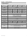
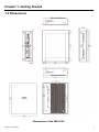
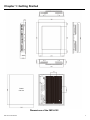
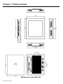
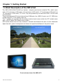
User Manual
IMP-A122/A152/A172/A192
Industrial Panel PC
___________________________________ Warning! ___________________________________
This equipment generates, uses and can radiate radio frequency energy and if not installed and
used in accordance with the instructions manual may cause interference to radio communications.
It has been tested and found to comply with the limits for a Class A computing device pursuant to
FCC Rules, which are designed to provide reasonable protection against such interference when
operated in a commercial environment. Operation of this equipment in a residential area is likely
to cause interference in which case the user at his own expense will be required to take whatever
measures may be required to correct the interference.
Electric Shock Hazard – Do not operate the machine with its back cover removed. There are
dangerous high voltages inside.
Disclaimer
This information in this document is subject to change without notice. In no event shall
Indumicro.com be liable for damages of any kind, whether incidental or consequential,
arising from either the use or misuse of information in this document or in any related
materials.
Table of Contents
Chapter 1: Getting Started
1.1 Specifications ……………………………………………………………………………
1
1.2 Dimensions ………………………………………………………………………………
2
1.3 Brief Description of the IMP-A1x2 ……………………………………………………
6
Chapter 2: BIOS Setup
2.1 Operations after POST Screen ………………………………………………………
7
2.2 BIOS Setup Utility ………………………………………………………………………
9
2.3 System Overview ……………………………………………………………………… 10
2.4 Advanced Settings
…………………………………………………………………… 11
2.5 Advanced PCI/PnP Settings ………………………………………………………… 20
2.6 Boot Settings …………………………………………………………………………… 23
2.7 Security Settings
……………………………………………………………………… 25
2.8 Advanced Chipset Settings …………………………………………………………… 27
2.9 Exit Options
…………………………………………………………………………… 31
Chapter 3: Installation
3.1 Configuring Penmount Windows 2000/XP/Vista/7 Driver ………………………..... 33
Chapter 4: Software
4.1 Software Functions ………………………………………………………………….... 42
4.2 Software Function Descriptions ……………………………………………………… 43
Appendices
A Panelmounting
………………………………………………………………………… 49
Chapter 1: Getting Started
1.1 Specifications
Model
Specs
IMP-A122[G]T
IMP-A152[G]T
IMP-A172[G]T
IMP-A192T
CPU
Intel Atom D525 1.8GHz processor FSB 800MHz
Chipset
Intel ICH8M
System Memory
1 x 204 Pin SO-DIMM DDR3 800GHz, up to 2GB SDRAM
Display Type
12” TFT
15” TFT
17” TFT
19” TFT
Resolution
800 x 600
1024 x 768
1280x1024
1280x1024
Max. Colors
262k
16.2M
16.2M
16.2M
H:130° / V:110°
H:160° / V:140°
H:170° / V:160°
H:170° / V:160°
350
400
550
350
Viewing Angle
2
Luminance (cd/m )
Backlight Lifetime
50,000 hrs
Touchscreen Type
Analog Resistive on ‘T’ models, GFG on ‘GT’ models
External Ports
4 x USB 2.0, 2 x Gigabit LAN, 1 x VGA,
2 x RS-232, 1 x RS-433/485, Audio
General Purpose I/O Port
1 x 8 Pin terminal block 2in/2out GPIO
Storage
1 x 160GB swappable HDD
Expansion Slots
None
Power Supply
11 ~ 32VDC
Construction
Heavy-duty steel front panel and housing
IP Rating
NEMA4/IP65 certified front
Mounting
Panel / VESA75
Panel / VESA75
Dimension (WxHxD) mm
317 x 243 x 76.6
410 x 310 x 70.6
Panel / VESA75
Panel / VESA100
439 x 348 x 71.1
484 x 400 x 74.5
o
Operating Temperature
0~50 C
Storage Temperature
-30~60oC
Relative Humidity
10~90% @40oC non-condensing
Vibration
5~17Hz, 0.1” double amplitude displacement / 17~640Hz,
1.5G acceleration peak to peak
Relative Humidity
10G acceleration peak to peak (11 millimeters)
Certificate
Meet CE / FCC Class A
IMP-A1x2 User Manual
1
Chapter 1: Getting Started
1.2 Dimensions
Panel
Cut-out
Dimensions of the IMP-A122
IMP-A1x2 User Manual
2
Chapter 1: Getting Started
Panel
Cut-out
Dimensions of the IMP-A152
IMP-A1x2 User Manual
3
Chapter 1: Getting Started
Panel
Cut-out
Dimensions of the IMP-A172
IMP-A1x2 User Manual
4
Chapter 1: Getting Started
Panel
Cut-out
Dimensions of the IMP-A192
IMP-A1x2 User Manual
5
Chapter 1: Getting Started
1.3 Brief Description of the IMP-A1x2
The IMP-A122/A152/A172/A192 are fanless / compact panel-mount industrial PCs, which come
with a 12" (luminance of 350 cd/m²), 15" (luminance of 400 cd/m²), 17" (luminance of 550 cd/m²) or
19" (luminance of 350 cd/m²) TFT LCD. They are powered by an Intel Atom D525 1.8 GHz dual
core processor.
These industrial panel PCs also feature three COM ports, four USB 2.0 ports, one 2.5” HDD drive,
a wide range DC 11~32V power input, etc.
The 'T' models are equiped with an analog resistive touch screen while the 'GT' models come
with a GFG (Glass-Film-Glass) touch screen.
GFG touch screens are not only resistant to scratch and abrasion but also to most chemicals.
Apart from that, glass is transparent and does not impair the brilliance of the picture at all.
Front and rear view of the IMP-A172
IMP-A1x2 User Manual
6
Chapter 2: BIOS Setup
2.1 Operations after POST Screen
After CMOS discharge or BIOS flashing operation, the system will display the following
screen for your further operation. Press F2 key to continue or F1 key to enter CMOS Setup.
IMP-A1x2 User Manual
7
Chapter 2: BIOS Setup
After optimizing and exiting CMOS Setup, the POST screen displayed for the first time is as
follows and includes basic information on BIOS, CPU, memory, and storage devices.
Press F11 key to enter Boot Menu during POST, as show by the following figure.
IMP-A1x2 User Manual
8
Chapter 2: BIOS Setup
2.2 BIOS Setup Utility
Press [Del] key to enter BIOS Setup utility during POST, and then a main menu containing
system summary information will appear.
IMP-A1x2 User Manual
9
Chapter 2: BIOS Setup
2.3 System Overview
System Time:
Set the system time, the time format is:
Hour:
0 to 23
Minute:
0 to 59
Second:
0 to 59
System date:
Set the system date, the date format is:
IMP-A1x2 User Manual
Day:
Note that ‘Day’ automatically changes when you set the date.
Month:
0 to 12
Date:
0 to 31
Year:
2010 to 2099
10
Chapter 2: BIOS Setup
2.4 Advanced Settings
IMP-A1x2 User Manual
11
Chapter 2: BIOS Setup
2.4.1 CPU Configuration
Max CPUID Value Limit:
[Disabled]
[Enabled]
Execute Disable Bit Capability:
[Disabled]
[Enabled]
Hyper Threading Technology:
[Disabled]
[Enabled]
IMP-A1x2 User Manual
12
Chapter 2: BIOS Setup
2.4.2 IDE Configuration
ATA/IDE Configuration:
[Enhanced]
[Disabled]
Configure SATA as:
[IDE]
[AHCI]
Hard Disk Write Protect:
[Disabled]
[Enabled]
IDE Detect Time Out:
[35]
[0, 5, 10, 15, 20, 25, 30, 35]
ATA(PI) 80Pin Cable Detection:
[Host & Device]
[Host]
[Device]
IMP-A1x2 User Manual
13
Chapter 2: BIOS Setup
2.4.3 Super IO Configuration
Serial Port3 Type*:
[RS232 Type]
[RS485 Type]
WatchDog Setting:
[Disable]
[10sec, 20sec, 30sec, 40sec, 1min, 2min, 4min]
*Select [RS485 Type] for RS485 or RS422 Mode
IMP-A1x2 User Manual
14
Chapter 2: BIOS Setup
2.4.4 Hardware Health Configuration
CPU Temperature:
Shows you the current CPU temperature.
CPUFAN Speed:
Shows you the current CPU Fan operating speed.
CPUFAN Mode Setting:
[Manual Mode]
[Thermal Cruise Mode]
[Speed Cruise Mode]
[Smart Fan 3 Mode]
2.4.5 ACPI Configuration
Section for Advanced ACPI Configuration
Options:
[Advanced ACPI Configuration]
[Chipset ACPI Configuration]
IMP-A1x2 User Manual
15
Chapter 2: BIOS Setup
2.4.6 AHCI Configuration
While entering setup, BIOS auto detect the presence of IDE devices. This displays the status
of auto detecting op IDE devices.
2.4.7 MPS Configuration
Configure the Multi-Processor Table.
MPS Revision:
[1.4]
[1.1]
IMP-A1x2 User Manual
16
Chapter 2: BIOS Setup
2.4.8 PCI Express Configuration
Relaxed Ordering:
[Auto]
[Disabled]
[Enabled]
Maximum Payload Size:
[Auto]
[128/256/512/1024/2048/4096 Bytes]
Set Maximum Payload or allow the System BIOS to select the value.
Extended Tag Field:
[Auto]
[Disabled]
[Enabled]
No Snoop:
[Auto]
[Disabled]
[Enabled]
Maximum Read Request Size:
[Auto]
[128/256/512/1024/2048/4096 Bytes]
Set Maximum Read Request Size of PCI Express Device or allow the System
BIOS to select the value.
IMP-A1x2 User Manual
17
Chapter 2: BIOS Setup
2.4.9 Smbios Configuration
Smbios Smi support:
[Enabled]
[Disabled]
2.4.10 USB Configuration
Legacy USB support:
[Enabled]
[Disabled]
IMP-A1x2 User Manual
18
Chapter 3: BIOS Setup
Legacy USB support:
[Enabled]
[Disabled]
USB2.0 Controller Mode:
[HiSpeed]
[FullSpeed]
BIOS EHCI Hand-Off:
[Enabled]
[Disabled]
Hotplug USB FDD support:
[Auto]
[Disabled]
[Enabled]
USB Mass Storage Device Configuration:
IMP-A1x2 User Manual
19
Chapter 2: BIOS Setup
2.5 Advanced PCI/PnP Settings
This part describes configurations to be made on the PCI bus system. PCI, short for Peripheral
Component Interface, is a computer bus that allows I/O to operate nearly as fast as the CPU
itself. Some technical terms will be mentioned here. We recommend that non-professional
user do not change the factory default settings.
Clear NVRAM:
[No]
[Yes]
Plug & Play OS:
[No]
[Yes]
IMP-A1x2 User Manual
20
Chapter 2: BIOS Setup
PCI Latency Timer:
[64]
[32]
[96]
[128]
[160]
[192]
[224]
[248]
Allocat IRQ to PCI/VGA:
[Yes]
[No]
Palette Snooping:
[Disable]
[Enable]
PCI IDE BusMaster:
[Disable]
[Enable]
Palette Snooping:
[Disable]
[Enable]
OffBoard PCI/ISA IDE Card:
Some PCI IDE cards may require to set the number of the PCI number that is holding the
card. ‘Auto’ works for most PCI IDE cards.
[Auto]
[PCI Slot1]
[PCI Slot2]
[PCI Slot3]
[PCI Slot4]
[PCI Slot5]
[PCI Slot6]
IMP-A1x2 User Manual
21
Chapter 2: BIOS Setup
IRQ3/4/5/7/9/10/11/14/15:
[Available]
[Reserved]
Available: Specified IRQ is available to be used by PCI/PnP devices.
Reserved: Specified IRQ is reserved for use by legacy ISA devices.
DMA Channel 0/1/3/5/6/7:
[Available]
[Reserved]
Available: Specified DMA is available to be used by PCI/PnP devices.
Reserved: Specified DMA is reserved for use by legacy ISA devices.
Reserved Memory Size:
Size of memory block to reserve for legacy ISA devices.
[Disabled]
[16]
[32k]
[64k]
IMP-A1x2 User Manual
22
Chapter 2: BIOS Setup
2.6 Boot Settings
Boot Setting Configuration:
Quick Boot:
Allows BIOS to skip certain tests while booting. This will decrease the time needed to boot
the system.
[Enabled]
[Disabled]
Quiet Booty:
[Disabled]
[Enabled]
Disabled: Displays normal POST messages.
Enabled Display OEM logo instead of POST messages.
IMP-A1x2 User Manual
23
Chapter 2: BIOS Setup
AddOn ROM Display Mode:
Set display mode for Option ROM.
[Force BIOS]
[Keep current]
Bootup Num-Lock:
Select Power-on state for Numlock.
[On]
[Off]
PS/2 Mouse Support:
Select support for PS/2 Mouse.
[Auto]
[Enabled]
[Disabled]
Wait For ‘F1’ If Error:
Wait for F1 key to be pressed if an error occurs.
[Enabled]
[Disabled]
Hit ‘DEL’ Message Display:
Displays “Press DEL to run Setup” in POST.
[Enabled]
[Disabled]
Interrupt 19 Capture:
[Disabled]
[Enabled]
Enabled: Allows option ROMs to trap interrupt 19.
Boot Device Priority:
Specifies the Boot Device Priority sequence.
IMP-A1x2 User Manual
24
Chapter 2: BIOS Setup
2.7 Security Settings
Change Supervisor Password:
Install or Change the Supervisor password.
Change User Password:
Install or Change the User Password.
Password Check:
[Setup]
[Always]
Setup: Check password when setup is invoked.
Always: Check password on each boot and when setup is invoked.
Boot Sector Virus Protection:
[Disabled]
[Enabled]
Enables / disables Boot Sector Virus Protection.
IMP-A1x2 User Manual
25
Chapter 2: BIOS Setup
Type a password of up to 6 characters and press the [Enter] key. This will clear all previously
typed CMOS passwords. You will be requested to confirm the password. Type the password again
and press [Enter]. You may press the [ESC] key to abandon the password entry operation.
To clear the password, just press the [Enter] key when the password input windows pops up. A
confirmation message will be shown as to whether the password will be disabled. You will have
direct access to BIOS setup without typing any password after system reboot once the password is
disabled.
Once the password feature is used, you will be requested to type the password each time you enter
BIOS setup. This will prevent unauthorized persons from changing your system configuration.
Also, the feature is capable of requesting users to enter the password prior to system boot to control
unauthorized access to your computer. Users may enable the feature in the Security Option of
Advanced BIOS Features. If the Security Option is set to Always, you will be requested to enter the
password before system boot and when entering BIOS setup; if the Security Option is set to Setup,
you will be requested to enter the password before entering BIOS Setup.
IMP-A1x2 User Manual
26
Chapter 2: BIOS Setup
2.8 Advanced Chipset Settings
Note: Due to the limited address length of BIOS, only a portion of the panel parameters are
listed in BIOS Setup. If the connected panel is not included in the parameter list, display
problems will occur. In this case please do not change BIOS setup.
2.8.1 North Bridge Configuration
IMP-A1x2 User Manual
27
Chapter 2: BIOS Setup
DRAM Frequency:
[Auto]
[Max MHz]
Configure DRAM Timing By SPD:
[Enabled]
[Disabled]
Initiate Graphic Adapter:
Select which graphics controller to use as the primary boot device
[IGD]
[PCI/IGD]
[PCI/PEG]
[PEG/IGD]
Internal Graphic Mode Select:
[Enabled, 8MB]
Video Function Configuration:
DVMT Mode Select:
[DVMT Mode]
[Fixed Mode]
IMP-A1x2 User Manual
28
Chapter 2: BIOS Setup
DVMT/FIXED Memory Size:
[256MB]
[128MB]
[Maximum DVMT]
Boot Display Device:
[BIOS-Default]
[CRT]
[LVDS]
[CRT+LVDS]
Flat Panel Type:
[1024x768]
[640x480]
[800x600]
[1280x1024]
[1400x1050]
[1600x1200]
Panel Backlight Control:
[Level9]
[Level0~15]
Note: Panel supports PWM function.
2.8.2 South Bridge Configuration
IMP-A1x2 User Manual
29
Chapter 3: BIOS Setup
USB Functions:
[6 USB Ports]
[Disabled]
[2 USB Ports]
[4 USB Ports]
[8 USB Ports]
USB 2.0 Controller:
[Enabled]
[Disabled]
82574L LAN1 Boot:
[Disabled]
[Enabled]
82574L LAN2 Boot:
[Disabled]
[Enabled]
LAN WakeUp:
[Disabled]
[Enabled]
HDA Controller:
[Enabled]
[Disabled]
SMBUS Controller:
[Enabled]
[Disabled]
SLP_S4# Min. Assertion Width:
[1 to 2 Seconds]
[4 to 5 seconds]
[3 to 4 seconds]
[2 to 3 seconds]
Restore on AC Power Loss:
[Turn On]
[Power Off]
[Last Status]
IMP-A1x2 User Manual
30
Chapter 2: BIOS Setup
2.9 Exit Options
Save Changes and Exit:
Save configuration changes and exit setup?
[OK]
[Cancel]
F10 key can also be used for this operation.
Discard Changes and Exit:
Discard changes and exit setup?
[OK]
[Cancel]
ESC key can also be used for this operation.
Discard Changes:
Discard changes?
[OK]
[Cancel]
IMP-A1x2 User Manual
31
Chapter 2: BIOS Setup
Load Optimized Defaults:
Load optimized defaults?
[OK]
[Cancel]
F9 key can also be used for this operation.
Load Fail-Safe Defaults:
Load fail-safe defaults?
[OK]
[Cancel]
F9 key can also be used for this operation.
IMP-A1x2 User Manual
32
Chapter 3: Installation
3.1 Configuring the PenMount Windows 2000/XP/Vista/7 Driver
Upon rebooting, the computer automatically finds the new 9036 controller board. The
touch screen is connected but not calibrated. Follow the procedures below to carry out
calibration.
1. After installation, click the PenMount Monitor icon “PM” in the menu bar.
2. When the PenMount Control Panel appears, click “Calibrate”.
PenMount Control Panel
The functions of the PenMount Control Panel are Calibrate, Draw, Multiple Monitors,
Option, and About, which are explained in the following sections.
Calibrate
This function offers two ways to calibrate your touch screen. “Standard Calibration”
adjusts most touch screens. “Advanced Calibration” adjusts aging touch screens.
Standard Calibration
Click this button and arrows appear pointing to red
squares. Use your finger or stylus to touch the red
squares in sequence. After the fifth red point
calibration is complete. To skip, press ‘ESC’.
Advanced Calibration
Advanced Calibration uses 4, 9, 16 or 25 points to
effectively calibrate touch panel linearity of aged
touch screens. Click this button and touch the red
squares in sequence with a stylus. To skip, press
‘ESC’.
IMP-A1x2 User Manual
33
Chapter 3: Installation
NOTE: The older the touch screen is, the more Advanced Mode calibration points you need
for an accurate calibration. Use a stylus during Advanced Calibration for greater
accuracy.
IMP-A1x2 User Manual
34
Chapter 3: Installation
Plot Calibration Data
IMP-A1x2 User Manual
Check this function and a touch panel linearity
comparison graph appears when you have finished
Advanced Calibration. The blue lines show linearity
before calibration and black lines show linearity
after calibration.
35
Chapter 3: Installation
Draw
Tests or demonstrates the PenMount touch screen operation. The display shows touch
location. Click Draw to start. Touch the screen with your finger or a stylus and the
drawing screen will register touch activity such as left, right, up, down, pen up, and
pen down.
Touch the screen with your finger or a stylus and the drawing screen will register touch
activity such as left, right, up, down, pen up, and pen down.
IMP-A1x2 User Manual
36
Chapter 3: Installation
Click Clear Screen to clear the drawing.
Multiple Monitors
Multiple Monitors support from 2 to 6 touch screen displays for one system.
The PenMount drivers for Windows 2000/XP/Vista/7 support Multiple Monitors. This
function supports from 2 to 6 touch screen displays for one system. Each monitor requires
its own PenMount touch screen control board, either installed inside the display or in a
central unit. The PenMount control boards must be connected to the computer COM
ports via the RS-232 interface. Driver installation procedures are the same as for a
single monitor. Multiple Monitors support the following modes:
Windows Extends Monitor Function
Matrox DualHead Multi-Screen Function
nVidia nView Function
NOTE: The Multiple Monitor function is for use with multiple displays only. Do not use this
function if you have only one touch screen display. Please note once you turn on this
function the rotating function is disabled.
IMP-A1x2 User Manual
37
Chapter 3: Installation
Enable the multiple display function as follows:
1. Check the Enable Multiple Monitor Support box; then click Map Touch Screens to
assign touch controllers to displays.
2. When the mapping screen message appears, click OK.
IMP-A1x2 User Manual
38
Chapter 3: Installation
3. Touch each screen as it displays “Please touch this monitor”. Following this
sequence and touching each screen is called mapping the touch screens.
4. Touching all screens completes the mapping and the desktop reappears on the
monitors.
5. Select a display and execute the “Calibration” function. A message to start calibration
appears. Click OK.
6. “Touch this screen to start its calibration” appears on one of the screens. Touch the
screen.
7. “Touch the red square” messages appear. Touch the red squares in sequence.
8. Continue calibration for each monitor by clicking Standard Calibration and touching
the red squares.
NOTES:
1. If you use a single VGA output for multiple monitors, please do not use the
Multiple Monitor function. Just follow the regular procedure for calibration on each
of your desktop monitors.
2. The Rotating function is disabled if you use the Multiple Monitor function.
3. If you change the resolution of display or screen address, you have to redo Map
Touch Screens, so the system understands where the displays are.
IMP-A1x2 User Manual
39
Chapter 3: Installation
About
This panel displays information about the PenMount controller and this driver version.
PenMount Monitor Menu Icon
The PenMount monitor icon (PM) appears in the menu bar of Windows 2000/XP system
when you turn on the PenMount Monitor in the PenMount Utilities.
The PenMount Monitor has the following functions:
Beep
IMP-A1x2 User Manual
Turns beep on or off.
40
Chapter 3: Installation
Right Button
When you select this function, a mouse icon appears
in the right-bottom of the screen. Click this icon to
switch between Right and Left Button functions.
Pen Stabilizer
Check this function to reduce cursor vibration for
relatively unstable touch screens, or where there may
be excess vibration. Normally this function is not
checked.
Exit
Exits the PenMount Monitor function.
PenMount Rotation Functions
There are currently a number of software packages on the market that support rotating
monitors 0°, 90°, 180°, and 270°. However you will not be able to use a touchscreen
unless it is matched to the appropriate rotation. Our rotation configuration function allows
you to easily match the touchscreen when you rotate your monitor.
If you use a rotating monitor you will need a display card such as from nVidia, Intel, SMI
or ATI and software such as Portrait Pivot Pro. For software operation and features,
please refer to your software manual.
Configuring the rotation function is easy. Select this option and a ‘point’ appears for you
to touch. Once the point is touched the software driver understands which degree you
plan to rotate your display. The rotation function supports 90, 180 and 270 degree
rotation.
NOTE: The rotating function is disabled if you use Monitor Mapping
IMP-A1x2 User Manual
41
Chapter 4: Software
4.1 Software Functions
This chapter describes the special software functions that configure and adjust the
PenMount controller board and touch screen hardware. Please note that not all of the
functions are available for every driver. Software functions and their availability for
specific interface and systems are shown in the table below—a description for each
function follows:
Software Function
DOS
Win 3.1
95
98/ME
NT
2000/XP VISTA/7
CE
Linux
QNX
●
/2003/
Standard Calibration
●
●
●
Advanced Calibration
●
●
●
●
●
●
●
●
●
●
●
●
Multiple Monitors
●
Multi Device
●
Rotation
●
Operation Mode
●
●
●
●
●
Drawing mode
●
●
●
●
●
●
Beep Sound
●
●
●
●
●
●
Beep sound adjustable
●
●
●
●
●
●
Showing linearity
●
●
●
●
●
●
●
●
●
●
●
●
●
●
Edge Compenstation
●
●
Refresh
●
●
Hide cursor
●
Double click area and
speed adjustable
About
●
●
●
●
●
●
●
●
●
Wake up function
Right button
●
●
●
●
Note: With PenMount Windows Universal V2.2.0.283 and later versions, the touchscreen
is automatically installed as a digitizer device in Windows Vista/7, the functions
which are built within Windows Vista / 7 such as rotation, multi-monitors, flicks, and
context menu function (which launches a context menu by user’s long-pressing on
touchscreen rather than clicking the right-mouse button or pressing the application
key on the keyboard) will be supported.
IMP-A1x2 User Manual
42
Chapter 4: Software
4.2 Software Function Description
Description for each of the software functions shown in the table above follows:
Standard Calibration
The Standard Calibration function lets you match the touch screen to your display so that
the point you touch is accurately tracked on screen. Standard calibration only requires
four points for calibration and one point for confirmation. Under normal circumstances,
Standard Calibration is all you need to perform an accurate calibration.
Advanced Calibration
The Advanced Calibration function improves the accuracy of calibration by using more
involved engineering calculations. Use this function only if you have tried the Standard
Calibration and there is still a discrepancy in the way the touch screen maps to the
display. You can choose 4, 9, 16 or 25 points to calibrate, though we suggest that you
first try 9 points, if it is still not tracking well then try 16 or 25 points. The more points you
use for calibration, the greater the accuracy. Errors in calibration may occur due to
viewing angle, or individual skill, and there may be little difference in using 16 or 25
points. Note that a stylus is recommended for the most accurate results.
Multiple Monitors
Until now most touch screen systems only support one monitor, and users of multiple
monitors have not been able to use touch screen systems. This situation has inspired
PenMount to design and develop Multiple Monitors support using the PenMount 9036
control board and Windows 2000/XP/Vista/7 driver. Our advanced design supports from
2 to 6 monitors that can be split horizontally or vertically.
Requirements
Before using the Multiple Monitor function, you need the following:
1. A display card that supports multiple monitors such as the Matrox, nVidia, ATI, etc.
(Two or more display cards supported by Windows are also OK.)
2. Two or more touch screens
3. Two or more serial ports
Before using Multiple Monitors you must have two or more monitors that are in extension
mode. For display cards that support multiple monitors, we suggest you consider Matrox,
nVidia, or ATI cards and inquire about operation and usability issues.
Note: Before you can use multiple monitors, you need to map each monitor.
IMP-A1x2 User Manual
43
Chapter 4: Software
Multiple Devices
The Multiple Devices function is designed to let you use two or more monitors to display
the same image.
Comparing Functions
The difference between the Multiple Monitors function and the Multiple Devices function
are illustrated below:
or
The Multiple Monitors function shown above extends the screen into 2 or more monitors.
The Multiple Devices function displays the same image on two or more monitors.
IMP-A1x2 User Manual
44
Chapter 4: Software
Requirements
Before using the Multiple Monitors function, you need the following:
1. A display card that supports Dual Monitors such as the Matrox, nVidia, ATI, etc.,
or that outputs into a 1-into-2 VGA signal box
2. Two or more touch screens
3. Two or more serial ports or USB ports
9000 Control Boards
To use multiple devices with 9000 Control Boards:
1. Configure your computer hardware.
2. Attach each 9000 Control Board to a different computer’s serial port.
3. Install the appropriate PenMount software driver in each computer.
4. Use each driver’s Calibration function to calibrate each computer’s touch screen.
You must calibrate each touch screen before configuration is complete.
Rotation
There are currently a number of software packages on the market that support rotating
monitors 0°, 90°, 180°, and 270°. However, you will not be able to use a touch screen
unless it is matched to the appropriate rotation. Our rotation configuration function allows
you to easily match the touch screen when you rotate your monitor.
If you use a rotating monitor, you will need a display card such as from nVidia, Intel, MSI
or ATI and software such as Portrait Pivot Pro. For software operation and features,
please refer to your software manual.
Configuring the rotation function is easy. Select this option and a ‘point’ appears for you
to touch. Once the point is touched, the software driver understands which degree you
plan to rotate your display. The rotation function supports 90, 180 and 270 degrees
rotation.
IMP-A1x2 User Manual
45
Chapter 4: Software
0 degrees
90 degrees
180 degrees
IMP-A1x2 User Manual
46
Chapter 4: Software
270 degrees
Stream/Point Mode
Stream and point modes control the touch and drag function of the touch screen. The
point mode only allows “touch” interaction with the screen and does not allow the user to
drag objects. The point mode is useful for maintaining the location of screen icons such
on POS terminals. The stream mode allows a user to touch and drag icons and other
items around on the screen, similar to using a mouse.
Drawing Mode
Drawing mode is a utility that lets the user draw on the screen using a finger or stylus.
This allows the user to test the touch screen and touch controller to see if it is operational
or is mapped correctly. The drawing mode can display either the matrix address of points
touched or just show lines drawn. One of the PenMount driver’s strengths is a special
mathematical algorithm that minimizes the occurrence of noise and smooths the drawing
of lines.
Beep Sound
All of PenMount’s drivers support the beep sound function; however, some PC systems
may only offer a fixed buzzer sound.
Beep Sound Adjustable
Software drivers for Windows systems let the user adjust the frequency and length of the
beep sound. The drivers let the user adjust the desired touch screen sound, as well as
turn the sound off.
IMP-A1x2 User Manual
47
Chapter 4: Software
Wake Up Function
The Wake Up function lets the user touch the screen and wake the system up from
‘suspend’ mode.
Point Calibration Data
The Plot Calibration Data function displays the touch screen linearity map, which is
available if the PenMount driver provides an Advance Calibration function when touch
screens age their touch linearity declines. This non-linearity is apparent when the
touched point on the touch screen is not the same as the point on the display. The plot
calibration data function shows the linearity status of the touch screen. This is only a
support function for the user. The exact linearity of a touch screen requires a linearity
test machine.
Right Button
The Right Button function simulates the right button function of a mouse. Click the right
button and the user can only touch the screen once and the driver changes the touch
definition to the left button.
Hide Cursor
The Hide Cursor function keeps the cursor arrow and other cursor symbols from
appearing when using the touch screen. The cursor appears when the user turns this
function off.
Cursor Offset
The Cursor Offset function lets the user adjust the position of the touch point to a desired
location away from the real touch point.
Double-Click Area and Speed
The Double-Click Area and Speed function lets the user adjust the double-click area and
speed to their personal preference.
About
This option shows the exact version of the drivers and controller firmware. Updated
drivers are available for download on the PenMount website.
IMP-A1x2 User Manual
48
Appendix A: Panel Mounting
Panel Mounting
The IMP-A1x2 industrial panel PC is designed to be panel-mounted as shown below. Just carefully
place the unit through the hole and tighten the given 8 screws from the rear to secure the mounting.
Panelmounting of the IMP-A1x2
How to Mount
1. Just insert the bracket into the hole
IMP-A1x2 User Manual
2. Slightly push the bracket back
as the arrow shows.
3. And screw it tight.
49
This page intentionally left blank.
Indumicro.com
The Netherlands
Phone +31 318 668 912
www.indumicro.com
[email protected]
Edition 1.0
©Indumicro.com