1
Omslag UNICORN OS
P
H
A
97-10-30 14.13
R
M
A
Sidan 1
C
I
A
B
I
O
UNICORN® OS
version 1.10
User Manual
18−1118−52
Edition AA
T
E
C
Omslag UNICORN OS
97-10-30 14.13
Sidan 2
Important user information
Reading this entire manual is
recommended for full understanding
of the use of this product.
Should you have any comments on this manual, we
will be pleased to receive them at:
Amersham Biosciences AB
Marketing Department
SE-75182 Uppsala
Sweden
Amersham Biosciences reserves the right to make
changes in the specifications without prior notice.
Warranty and Liability
Amersham Biosciences AB guarantees that the product
delivered has been thoroughly tested to ensure that
it meets its published specifications. The warranty
included in the conditions of delivery is valid only
if the product has been installed and used
according to the instructions supplied by
Amersham Biosciences AB.
Amersham Biosciences shall in no event be liable
for incidental or consequential damages, includi
without limitation, lost profits, loss of income, l
of business opportunities, loss of use and other
related exposures, however caused, arising from
the faulty and incorrect use of the product.
Trade marks
UNICORN, OligoPilot II, OligoProcess and Prim
Support are the exclusive trade marks of
Amersham Biosciences AB. In view of the risk of tra
mark degeneration, it is respectfully suggested th
authors wishing to use these designations refer t
their trade mark status at least once in each artic
Copyright© 1997 Amersham Biosciences A
All rights reserved. No part of this publication m
be reproduced, stored in a retrieval system or
transmitted in any form or by any means withou
in written permission from the company.
__________________________________________________________________ Preface
Preface
About this manual
This manual provides reference to UNICORN® for Oligo Synthesis
version 1.10, referred to as UNICORN OS, from Amersham Biosciences
AB. UNICORN OS is a complete package for control and supervision
of oligonucleotide synthesis systems, suitable for use with Amersham
Biosciences OligoPilot II and OligoProcess. All functionality associated
with UNICORN OS consists of software which runs on an IBMcompatible PC under the OS/2 operating environment, and hardware
for interfacing the controlling PC to the synthesis module.
The control platform and functions within UNICORN OS are
essentially the same as for UNICORN version 2.10, the latter
developed by Amersham Biosciences for chromatographic separations.
UNICORN OS is supplied with system strategies and templates for
oligonucleotide synthesis, although it is possible to perform
chromatographic separations associated with UNICORN by obtaining
the appropriate strategies and templates from Amersham Biosciences.
In the writing of this manual, those functions that are directly relevant
for UNICORN OS are described. Functions that are more relevant to
chromatographic separations, such as Scouting, BufferPrep and some
evaluation functions are not discussed in this manual.
This manual is organized into 13 chapters and 6 appendices:
Introductory material
1. Introduction
2. UNICORN OS concepts
3. Login and file handling
Methods and runs
4. Creating methods from method templates
5. Creating and editing methods
6. Performing a run
Evaluation
7. Presenting results
8. Evaluating results
System management
9. Security features
10. Network setup
11. Installation
12. Administration
13. System settings
Appendices
A. Technical specifications
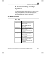
B. Strategy for Oligo Synthesis
C. Evaluation functions and instructions
D. Feedback tuning
E. File Organization
F. Troubleshooting
UNICORN for Oligo Synthesis version 1.10 User Manual 18-1118-52 Edition AA
i
Preface__________________________________________________________________
Assumptions
Two broad assumptions are made in this manual:
1.
You should be familiar with the oligonucleotide synthesis systems
in your installation. Refer to the appropriate system user manuals
for details.
2.
You should be familiar with the general principles of using IBM’s
OS/2 operating system on your PC. Although UNICORN OS is a
self-contained program package and does not require any direct
interaction by the user with OS/2, the user interface principles
follow the conventions set by the OS/2 operating environment.
Typographical conventions
Menu commands and dialogue box prompts are identified in the text
by a Helvetica typeface. A colon separates menu levels: thus File:Open
refers to the Open command in the File menu.
A typewriter-like typeface is used for instructions as they appear in
the text editor for methods and evaluation procedures. These are
normally entered automatically by UNICORN OS.
ii
UNICORN for Oligo Synthesis version 1.10 User Manual 18-1118-52 Edition AA
_________________________________________________________________ Contents
Contents
Introductory material _________________________________________
1. Introduction
1-1
2. UNICORN OS concepts
2-1
2.1 UNICORN OS user interface
2-1
2.1.1 UNICORN OS control software
2.1.2 Stand-alone and network installations
2.1.3 Software modules
2.1.4 OS/2 terminology
2.1.5 On-line help
2.2 Files and directories
2.2.1 Method files
2.2.2 Result files
2.3 Methods
2.3.1 Method structure
2.4 System control
2-1
2-2
2-2
2-4
2-5
2-6
2-6
2-6
2-6
2-7
2-10
2.4.1 Control facilities
2.4.2 System connections
2-10
2-11
2.5 Evaluation
2.6 Network considerations
2.7 Security
2-11
2-12
2-14
3. Login and file handling
3-1
3.1 Logging in
3.2 UNICORN OS desktop
3.2.1 Icons and windows
3.2.2 UNICORN OS Main menu panels
3.2.3 Presenting files
3.2.4 Finding files
3.2.5 Copying, moving and renaming files
3.2.6 Deleting files
3.2.7 Backup security
3.3 Logging out
3.4 Quitting UNICORN OS
3-1
3-2
3-2
3-3
3-4
3-7
3-8
3-9
3-9
3-10
3-10
Methods and Runs ___________________________________________
4. Creating methods from method templates
4-1
4.1 Creating a new method
4.2 Saving and running a test sequence method
4.3 Creating a sequence and method
4.4 Editing method variables
4-2
4-3
4-4
4-6
UNICORN for Oligo Synthesis version 1.10 User Manual 18-1118-52 Edition AA
i
Contents_________________________________________________________________
4.5 Method notes
4.6 Saving the method
4.7 Starting a run
4.8 Editing text instructions
4-9
4-10
4-11
4-12
5. Creating and editing methods
5-1
5.1 The sequence editor
5.1.1 Modifying cross references in the sequence editor
5.2 Text instructions editor
5.3 Method blocks
5.3.1 Viewing blocks
5.3.2 Calling blocks
5.3.3 Adding blocks
5.3.4 Deleting blocks
5.3.5 Renaming blocks
5.3.6 Importing and copying blocks
5.4 Method instructions
5.4.1 Viewing instructions
5.4.2 Adding instructions
5.4.3 Deleting instructions
5.4.4 Changing instructions
5.4.5 The flow scheme window
5.5 Method variables
5.5.1 Identifying variables
5.5.2 Defining variables
5.5.3 Removing a variable
5.5.4 Renaming a variable
5.6 Run setup
5.6.1 Variables
5.6.2 Questions
5.6.3 Method notes
5.6.4 Evaluation procedures
5.6.5 Info
5.6.6 Sequence
5.6.7 Result
5.6.8 Start protocol
5.7 Saving the method
5.7.1 Saving as a method
5.7.2 Saving as a template
5.7.3 Deleting a template
5-3
5-6
5-8
5-8
5-9
5-10
5-13
5-14
5-15
5-16
5-16
5-17
5-19
5-19
5-21
5-22
5-22
5-23
5-24
5-25
5-25
5-25
5-27
5-30
5-31
5-34
5-34
5-35
5-36
5-38
5-38
5-39
5-39
5.8 How to use selected method instructions
5-40
5.8.1 BASE and METHODBASE instructions
5.8.2 Instructions at the same breakpoint
5.8.3 Controlling block and method length
5.8.4 Messages
5.8.5 Pausing a method
5.8.6 Linear flow rates
5.8.7 Conditional instructions
5-40
5-40
5-41
5-42
5-43
5-43
5-43
5.9 Creating methods “from scratch”
ii
5-2
5-47
UNICORN for Oligo Synthesis version 1.10 User Manual 18-1118-52 Edition AA
_________________________________________________________________ Contents
6. Performing a run
6.1 Starting a method
6.1.1 Starting from the Main menu
6.1.2 Starting from System control
6.1.3 Start protocol
6.2 Monitoring a run
6.2.1 General panel techniques
6.2.2 Run data
6.2.3 Curves
6.2.4 Flow scheme
6.2.5 Logbook
6.3 Manual control
6-1
6-1
6-1
6-2
6-3
6-4
6-4
6-5
6-6
6-8
6-8
6-9
6.3.1 The control bar
6.3.2 Manual instructions
6.3.3 Alarms and warnings
6-9
6-11
6-12
6.4 If communication fails
6-13
6.4.1 Network failure
6.4.2 Local station failure
6-13
6-13
6.5 Managing system connections
6-13
6.5.1 Establishing a connection
6.5.2 Connection modes
6.5.3 Leaving and locking a system
6.5.4 Disconnecting a system
6.5.5 Network considerations
6-13
6-15
6-16
6-16
6-17
6.6 Calibrating monitors
6-18
Evaluation __________________________________________________
7. Presenting results
7-1
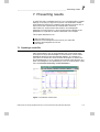
7.1 Opening a result file
7-1
7.1.1 Chromatogram
7.1.2 Documentation icon
7.1.3 Temporary icon
7.2 Basic presentation of chromatograms
7.2.1 Viewing chromatograms
7.2.2 The Chromatogram Layout dialogue box
7.2.3 Selecting a layout
7.2.4 Choosing the curve(s) you want to see
7.2.5 Curve and chromatogram names
7.2.6 Changing the colour and style of curves
7.2.7 Changing and fixing the axes
7.2.8 Viewing information about the run
7.2.9 Saving a layout
7.3 Additional presentation possibilities
7.3.1 Showing part of a curve
7.3.2 Entering text in the chromatogram
7.4 Comparing different runs
7.4.1 Comparing chromatograms from different runs
UNICORN for Oligo Synthesis version 1.10 User Manual 18-1118-52 Edition AA
7-2
7-2
7-5
7-5
7-5
7-7
7-7
7-7
7-8
7-9
7-10
7-11
7-12
7-12
7-13
7-16
7-17
7-17
iii
Contents_________________________________________________________________
7.4.2 Overlaying curves
7.4.3 Stacking and stretching curves
7.4.4 Mirror images of curves
7.5 Saving results
7.6 Printing chromatogram and documentation reports
7.6.1 Saving a report format
7.6.2 Selecting a format
7.6.3 Printer set-up
7.6.4 Printing active chromatograms
7-20
7-24
7-27
7-28
7-28
7-31
7-32
7-32
7-32
7.7 Exiting Evaluation
7-32
8. Evaluating results
8-1
8.1 Integrating peaks
8-1
8.1.1 Baseline calculation for integration
8.1.2 Performing a basic integration
8.1.3 Optimizing peak integration
8.1.4 Manually editing a baseline
8.1.5 Adjusting the peak boundaries
8.1.6 Measuring HETP
8.1.7 Measuring peak asymmetry
8.2 Other evaluations
8.2.1 Finding the slope values for Watch instructions
8.2.2 Creating a curve
8.3 Automated evaluation procedures
8.3.1 Recording a procedure
8.3.2 Editing an existing procedure
8.3.3 Points to watch
8.3.4 Running evaluation procedures
8.3.5 Batch runs
8.3.6 Evaluation procedures and reports
8.3.7 Placing a procedure on the menu and running
8.4 Exporting data or curves
8.4.1 Exporting results
8.4.2 Copying results to the clipboard
8-1
8-2
8-4
8-5
8-7
8-10
8-11
8-11
8-11
8-13
8-15
8-15
8-17
8-18
8-19
8-19
8-20
8-21
8-22
8-22
8-24
System management ________________________________________
9. Security features
9-1
9.1 Access security
9.2 Connection security
9.3 Data security
9-1
9-1
9-2
9.3.1 Network communication failure
9.4 Security recommendations for control stations
10. Network setup
10.1 Summary of network setup procedures
10.2 Introduction
10.3 Network organization
iv
9-2
9-3
10-1
10-1
10-2
10-2
UNICORN for Oligo Synthesis version 1.10 User Manual 18-1118-52 Edition AA
_________________________________________________________________ Contents
10.4 Network requirements
10.5 Shared network resources
10.6 Named pipes
10.7 Startup files
10.8 System and user definitions
11. Installation
11.1 Installation summary
11.2 System requirements
11.2.1 Hardware requirements
11.2.2 Software requirements
11.3 Hardware installation
11.4 Software installation
10-4
10-5
10-5
10-7
10-8
11-1
11-1
11-1
11-1
11-2
11-2
11-3
11.4.1 Installing UNICORN OS for the first time
11-3
11.4.2 Installing selected software components after the initial installation11-9
11.4.3 Installing software upgrades
11-10
12. Administration
12-1
12.1 System definitions
12-2
12.1.1 Defining and editing systems
12.1.2 Deleting system definitions
12.1.3 Changing strategies
12.2 Access levels
12.2.1 Defining access levels
12.2.2 Access level examples
12.3 User administration
12.3.1 Defining new users
12.3.2 Changing user passwords
12.3.3 Viewing and changing user definitions
12.3.4 Deleting users
12.3.5 Defining new home directories
12.3.6 Deleting home directories
12.4 Audit trails
12.4.1 Examining audit trails
12.4.2 Renewing audit trail files
12.4.3 Backing up audit trail files
12.4.4 System run hours
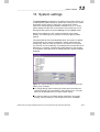
13. System settings
13.1 Alarms
13.2 Specials
13.3 Monitors
13.4 Curves
UNICORN for Oligo Synthesis version 1.10 User Manual 18-1118-52 Edition AA
12-2
12-4
12-4
12-5
12-5
12-7
12-10
12-11
12-12
12-13
12-13
12-13
12-14
12-15
12-15
12-17
12-18
12-18
13-1
13-2
13-4
13-4
13-5
v
Contents_________________________________________________________________
Appendices ________________________________________________
A. Technical specifications
A-1
A.1 System requirements
A-1
A.1.1 Hardware requirements
A.1.2 Software requirements
A.1.3 Network requirements
A.2 Control capacity
A.2.1 Stand-alone installations
A.2.2 Network installations
A.3 Data sampling
B. General strategy for Oligo Synthesis
A-2
A-2
A-2
A-2
B-1
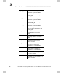
B.1 Method instructions
B-1
B.1.1 Pump
B.1.2 Flowpath
B.1.3 Alarms&Monitors
B.1.4 Watch
B.1.5 Other
B-1
B-3
B-5
B-6
B-7
B.2 Manual control instructions
B.2.1 Pump
B.2.2 Flowpath
B.2.3 Alarms&Monitors
B.2.4 Other
B.3 System settings instructions
B.3.1 Alarms Settings
B.3.2 Specials Settings
B.3.3 Monitors Settings
B.3.4 Curve Configuration
B.3.5 Method variables
C. Evaluation functions and instructions
B-8
B-8
B-8
B-8
B-8
B-9
B-9
B-9
B-10
B-11
B-11
C-1
C.1 Smoothing algorithms
C-1
C.1.1 Moving Average
C.1.2 Autoregressive
C.1.3 Median
C-1
C-1
C-2
C.2 Baseline calculation theory
C.2.1 Finding baseline segments
C.2.2 Selecting baseline points
C.2.3 Drawing the baseline
C.2.4 Estimating the baseline parameters from the source curve
C.3 Peak table column components
C.4 Evaluation procedure instructions
C.4.1 Curve operations
C.4.2 Integration
C.4.3 File Operations
C.4.4 Export
C.4.5 Chromatogram functions
C.4.6 Other
vi
A-1
A-1
A-1
C-3
C-3
C-5
C-5
C-5
C-7
C-10
C-10
C-12
C-13
C-13
C-15
C-16
UNICORN for Oligo Synthesis version 1.10 User Manual 18-1118-52 Edition AA
_________________________________________________________________ Contents
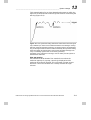
D. Feedback tuning
D-1
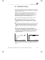
D.1 Flow rate tuning
D.2 Gradient tuning
D-2
D-3
E. File organisation
E-1
E.1 Stand-alone installations
E.2 Network installations
E.2.1 Local and remote computers
E.2.2 Network server
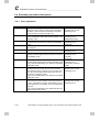
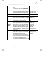
F. Troubleshooting
F.1 Start-up problems
F.1.1 Warning signal from computer
F.1.2 UNICORN OS fails to start
F.1.3 OS/2 cannot create swap file
F.2 Login problems
F.2.1 Unable to log in to UNICORN OS
F.2.2 Error message “Strategy file error”
F.3 UNICORN OS access problems
F.3.1 Unable to access certain UNICORN OS functions
F.3.2 Connections are not available
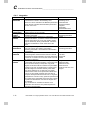
F.4 Method and run problems
E-1
E-1
E-1
E-1
F-1
F-1
F-1
F-1
F-2
F-2
F-2
F-2
F-3
F-3
F-3
F-4
F.4.1 Cannot switch from control to view mode
F-4
F.4.2 Monitor signals do not appear in the System control Curves panel F-4
F.4.3 Error message “Couldn’t create result file...”
F-4
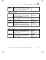
F.5 Evaluation problems
F.5.1 Incorrect date and time
F.5.2 Evaluation procedure aborts
F.6 Other problems
UNICORN for Oligo Synthesis version 1.10 User Manual 18-1118-52 Edition AA
F-5
F-5
F-5
F-5
vii
Contents_________________________________________________________________
viii
UNICORN for Oligo Synthesis version 1.10 User Manual 18-1118-52 Edition AA
Introductory material
Methods and Runs
Evaluation
System management
Appendices
This page is deliberately left blank.
__________________________________________________________ Introduction
1
1. Introduction
UNICORN OS is an adapted version of the UNICORN control system
which allows real-time control of oligonucleotide synthesis systems
from a personal computer. The package operates together with
OligoPilot II and OligoProcess from Amersham Biosciences UNICORN
OS runs under the operating system OS/2 Warp version 3.0 or higher
from IBM.
Functional features of UNICORN OS include:
One PC may control up to 4 synthesis (and/or chromatographic
separation) systems directly.
Network support allows any number of systems to be run from one
PC.
Method templates, providing method frameworks for most common
applications, eliminate the need to program methods from scratch.
Modular methods are defined in the method templates, reflecting
the separate steps in a synthesis process, e.g. detritylation, coupling,
oxidation/thiolation, capping and wash/purge steps.
Dynamic graphical overview of active runs.
User-definable alarm and warning limits for monitor signals.
Batch operation and process documentation in accordance with the
requirements of Good Manufacturing Practice (GMP) and Good
Laboratory Practice (GLP).
In addition, UNICORN OS offers a comprehensive security system:
Password control for all users, with access authorization for other
users’ method and result files.
Customized definition of access control levels.
Audit trail for system operation.
Note: UNICORN OS must be correctly installed for stand-alone or
network operation before the software can be used. Network
considerations, software installation and administration of
system and user definitions are described in Chapters 10, 11
and 12 of this User Manual.
UNICORN for Oligo Synthesis version 1.10 User Manual 18-1118-52 Edition AA
1-1
1
1-2
Introduction__________________________________________________________
UNICORN for Oligo Synthesis version 1.10 User Manual 18-1118-52 Edition AA
________________________________________________ UNICORN OS concepts
2
2. UNICORN OS concepts
This chapter introduces the basic concepts that are needed to use
UNICORN OS. For a description of general concepts of how to work
with the OS/2 operating system, see your OS/2 system documentation.
Material in this chapter is divided into 7 sections, dealing with:
UNICORN OS user interface
Files and directories
Methods and method structure
System control
Evaluation
Network considerations
Security and administration
2.1 UNICORN OS user interface
2.1.1 UNICORN OS control software
UNICORN OS runs under the OS/2 operating system, and provides
facilities for method-controlled operation of oligonucleotide synthesis
systems as well as real-time monitoring and subsequent evaluation of
the synthesis process.
Strategies
Part of UNICORN OS software (referred to as the strategy) is system
specific. The strategy defines what is available in method and manual
instructions, system settings, run data, curves and method templates.
Most of this manual describes the user interface in UNICORN OS
independent of the strategy. Strategy-dependent instructions are listed
in Appendix B.
UNICORN for Oligo Synthesis version 1.10 User Manual 18-1118-52 Edition AA
2-1
2
UNICORN OS concepts _________________________________________________
2.1.2 Stand-alone and network installations
UNICORN OS may be installed either on a stand-alone computer or in
a network.
In a stand-alone installation, up to four oligonucleotide synthesis
(and/or chromatographic separation) systems may be physically
connected to and controlled from the computer where UNICORN
OS is installed.
In a network installation, each oligonucleotide synthesis system is
physically connected to one computer in the network, but may be
controlled from any computer in the network on which the software
is installed. A computer to which oligonucleotide synthesis systems
are physically connected is referred to as a local station. Other
computers in a network installation are called remote stations.
Note:
It is not necessary to install UNICORN OS for network
control if you only want to be able to save method and result
files on a server disk. Just define a home directory on the server
disk if the computer itself is connected to a network (see
Section 11.4.1).
2.1.3 Software modules
UNICORN OS control software consists of four integrated modules:
The Main menu, with functions for file handling and administrative
routines such as definition of available oligonucleotide synthesis
systems and maintenance of user profiles.
The Method editor, where methods for pre-programmed control of
oligonucleotide synthesis systems are created and edited.
The System control module, which permits manual or method-based
control of oligonucleotide synthesis systems and on-line monitoring
of synthesis processes. There may be up to four independent System
control modules on one computer, for controlling up to four separate
systems.
The Evaluation module, for viewing and presenting stored results
from synthesis processes.
2-2
UNICORN for Oligo Synthesis version 1.10 User Manual 18-1118-52 Edition AA
________________________________________________ UNICORN OS concepts
2
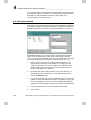
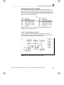
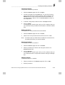
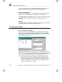
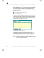
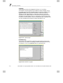
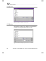
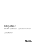
Figure 2-1. UNICORN OS desktop with the Main menu shown as a window
and the other modules as icons.
These modules are represented by either windows or icons on
UNICORN OS desktop (see Figure 2-1). UNICORN OS desktop itself
occupies the entire screen. According to how the software is installed,
you may be able to minimize UNICORN OS to allow access to other
programs on the OS/2 desktop.
UNICORN for Oligo Synthesis version 1.10 User Manual 18-1118-52 Edition AA
2-3
2
UNICORN OS concepts _________________________________________________
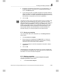
2.1.4 OS/2 terminology
This section explains some of the basic terms relating to the OS/2 user
interface. Refer to your OS/2 documentation for a complete
description.
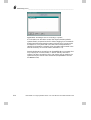
Figure 2-2. Main components of the OS/2 user interface.
The desktop is the area of the screen in which windows can be
opened. UNICORN OS has its own desktop which may occupy all or
part of the screen.
An icon is a symbol on the desktop or in a window representing an
object in the interface (usually a file or program). In general, doubleclick on an icon with the left mouse button to open the icon to a
window. Double-clicking on an icon on the OS/2 desktop generally
starts the program associated with the icon. Icons on UNICORN OS
desktop represent modules in UNICORN OS software, and doubleclicking on a module icon opens the window for the module.
A window is an active area of the desktop used by a program or an
open folder displaying its contents. There may be several windows
open at the same time on the OS/2 desktop, but only one is active at
any one time. The active window is generally identified by the colour
of the title bar and border. In UNICORN OS the Autominimize
setting under Preferences in the Main menu determines whether
several windows can be open at the same time. The recommended
setting with Autominimize selected reduces the active window to the
corresponding icon if another module is opened, reducing potential
confusion on UNICORN OS desktop.
2-4
UNICORN for Oligo Synthesis version 1.10 User Manual 18-1118-52 Edition AA
________________________________________________ UNICORN OS concepts
2
Drag the window border to change the size of the window.
Use the scroll bars to scroll the window contents. Scroll bars are only
shown when the window contents do not fit in the current window
size.
Each window has a title bar which identifies the program or folder
(in OS/2) or module (in UNICORN OS) associated with the window.
In UNICORN OS, the title bar for the System control window can be
set to different colours according to the identity of the
oligonucleotide synthesis system connected to the window (see
Section 14.1).
Maximize
Restore
At the right hand end of the title bar are buttons for quickly adjusting
the size of the window. Clicking on the Maximize button enlarges the
window to fill the desktop. At the same time, the button changes to
the Restore button, which restores the window to its previous size. If
the window is not maximized, you can drag the window borders to
adjust the size of the window.
Note: Depending on how UNICORN OS has been installed, there
may also be a minimize button to reduce the window to an
icon.
At the left hand end of the title bar on OS/2 windows is a button for
window control functions. This button is not used in UNICORN OS
windows.
The Launchpad is located on the OS/2 workspace and allows
applications to be launched with a single click of the mouse button. It
is possible to link the UNICORN OS icon to the Launchpad.
Application program windows (including UNICORN OS) have a
menu bar with menu commands (see Figure 2-1). Click on a menu
item or press <Alt> followed by the underlined letter in the item to
open the menu. Click on a command in the menu or press the
underlined letter in the command to activate the command.
2.1.5 On-line help
Help
A comprehensive on-line help utility is included in UNICORN OS
software. Choosing Help from the menu or pressing function key F1
provides an entry to the help texts for the currently active module.
Contents, Search and Index functions help the user to find information
for all modules, regardless of which module is currently active. Most
dialogue boxes have a Help button for help on how to use the currently
open dialogue box.
UNICORN for Oligo Synthesis version 1.10 User Manual 18-1118-52 Edition AA
2-5
2
UNICORN OS concepts _________________________________________________
In the instructions boxes for method instructions, procedure
instructions and system settings, pressing F1 when an instruction is
highlighted will display an information box with short help on the
function and usage of the selected instruction.
2.2 Files and directories
UNICORN OS Main menu interface divides user files into two
categories, for methods and results (see Figure 2-1). Only directories to
which the current user has access are shown in the Main menu panels.
Files may be displayed in icon view or details view in the Main menu
panel (see Chapter 3 for more details).
2.2.1 Method files
Method files contain instructions for controlling a run and are shown
in the Methods panel of the Main menu.
2.2.2 Result files
Result files are created by UNICORN OS when a synthesis process is
run and contain:
Settings for the synthesis run (method variables and questions)
File name, sequence and description for the sequence
Efficiency values for each coupling stage
2.3 Methods
Oligonucleotide synthesis runs are programmed as methods in
UNICORN OS. UNICORN OS is supplied with method templates
which enable most synthesis processes to be performed. The user needs
only to insert the desired sequence into the sequence editor and then
click on the associated Create button to automatically produce a readyto-run method (see Chapter 4). For more advanced usage, it is possible
to edit and create methods for specific synthesis processing needs (see
Chapter 5).
2-6
UNICORN for Oligo Synthesis version 1.10 User Manual 18-1118-52 Edition AA
________________________________________________ UNICORN OS concepts
2
2.3.1 Method structure
This section introduces the main components of a method and how
they are structured. In most cases, it is sufficient to just run the method
after you have provided information about the sequence you want to
synthesize (see Section 4.3). More advanced usage of UNICORN OS
requires that you understand the principles and concepts of methods.
Blocks
Methods in UNICORN OS are usually divided into blocks. Blocks
typically contain the subroutines that control the complete synthesis
procedure. A synthesis cycle is generally based on the following order
of subroutines:
Detritylation
Detrit wash
Coupling
Oxidation/thiolation
Capping
Method templates supplied with UNICORN OS contain all the blocks
that are likely to be used in a specific method. When the desired
sequence is created, the blocks needed to build up the method to
synthesize the sequence are automatically copied in from the method
template. The methods derived from the method templates can be
directly used to process the run.
Additionally, the methods are convenient starting points for developing
customized methods. Fully adequate customized methods for many
applications can be created simply by adjusting the values of method
variables (see below). New blocks can also be created in the Text
instructions or in the cross reference list of the Sequence page in Run
setup.
Method base
Method blocks are written in one of three method bases, which defines
the unit for the breakpoints in the block:
time (min)
volume (ml or l according to the strategy)
column volume (set by the user)
UNICORN for Oligo Synthesis version 1.10 User Manual 18-1118-52 Edition AA
2-7
2
UNICORN OS concepts _________________________________________________
Different blocks in the same method may be written with different
method bases: for example a column wash block might be written in
terms of column volumes while a purge block might be best expressed
in absolute volume.
Note:
The term method base should not be confused with bases in a
sequence or an oligonucleotide.
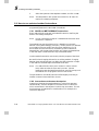
Instructions
The method is a call to blocks, with each block containing a series of
instructions or sub-routines (see Figure 2-3). Each instruction is a
request for specific operations in the system. A block may also contain
other blocks which in turn contain their own series of instructions.
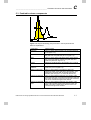
Double click on a block to expand/collapse the view of the instructions.
Figure 2-3. Relationship between blocks and instructions. The method (left)
is written as a series of calls to blocks, each of which consists of instructions
for performing one or more specified tasks (right).
Breakpoints
Each instruction in a method block is issued at a specified breakpoint
according to the method base. The first instruction in a block is always
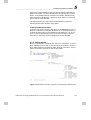
at breakpoint 0, and all other breakpoints are counted from this point.
For example, in the following instructions from a block:
0.00
0.00
9.00
2-8
Base Time
Flow_Reag 5.00 {ml/min}
Flow_Reag 0.00 {ml/min}
UNICORN for Oligo Synthesis version 1.10 User Manual 18-1118-52 Edition AA
________________________________________________ UNICORN OS concepts
2
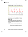
At breakpoint 0.00, the reagent flow rate is set to 5.00 ml/min. After
nine minutes have elapsed, at the next breakpoint, the flow rate of the
reagent will be set at 0.00 ml/min, i.e. no flow at all.
Method variables
Breakpoint values and instruction parameters may be defined as
variables. This is a powerful facility for constructing a method which
contains default parameter values. These default values may then easily
be changed either to create variants of the same method or to adjust the
parameter values at the start of a run (see Section 4.4).
Using variables makes it easy to adapt a method to a particular
oligonucleotide synthesis run. For example, in the block below, the
values of the start parameters variables can be seen:
(START parameters)
0.00 Base SameAsMain
0.00 Scale (2)#Weight_of_support {g},
(90)#Loading_of_support {umol/g}
0.00 DelayVol 2.00 {ml}
0.00 ColDiam (20)#Col_Diam {mm}
4.00 End_block
The variables are expressed:
(variable value)#Variable_type{ variable units }.
In the block above, it is possible to see that the variable values have
been set at 2 g weight of support, 90 µmol/g loading of support and a
20 mm column diameter.
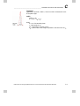
By using variables, a method may be displayed either in detail as text
instructions or in a condensed form as variable values in Run setup
mode. This is illustrated in Figure 2-4. The Run setup mode is displayed
when the method is run, allowing variable values to be set at the
beginning of the run.
Figure 2-4. Relationship between variables in text instructions and in the
Variables page of run set-up.
UNICORN for Oligo Synthesis version 1.10 User Manual 18-1118-52 Edition AA
2-9
2
UNICORN OS concepts _________________________________________________
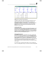
2.4 System control
2.4.1 Control facilities
The System control module allows independent control of up to four
oligonucleotide synthesis systems from one computer, with continuous
real-time monitoring of the synthesis process. The run status can be
displayed as:
numerical display of run data from selected monitors
graphical display of curves from monitors
a flow scheme showing the current flow path in the system
a logbook recording the control events in the run.
Systems can be controlled either manually with interactive commands
or through pre-programmed methods.
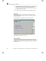
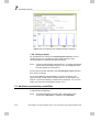
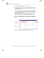
Figure 2-5. The System control window with run data and curves displayed.
2-10
UNICORN for Oligo Synthesis version 1.10 User Manual 18-1118-52 Edition AA
2
________________________________________________ UNICORN OS concepts
2.4.2 System connections
To control a synthesis process, the operator establishes a connection
between the computer and the oligonucleotide synthesis system in one
of the System control windows on UNICORN OS desktop. Two kind
of connections may be established:
Control mode connections which permit full control of the connected
system.
View mode connections from which the progress of the synthesis can
be monitored but the system cannot be controlled.
Each oligonucleotide synthesis system may have only one control mode
connection but may have several view mode connections. In a network
installation, the same or different users may establish simultaneous
view mode connections to one system on different computers. This
allows a running process to be monitored from several locations at the
same time.
The actual control of running processes is handled by the local
computer. A user may disconnect a control mode connection without
affecting the running process.
2.5 Evaluation
The Evaluation module provides extensive facilities for presentation
and evaluation of synthesis results. Essential features of evaluation
include:
Trityl data. This is stored in the result file and can be printed in a
report as a table
Curve manipulation. A wide range of operations can be performed
on curves, such as addition and subtraction of two curves,
differentiation, normalization and scaling. The original raw data
curves are always kept unmodified in the result file.
Curve comparisons. Curves from different result files can easily be
compared in the Evaluation module.
Evaluation procedures. Operations performed in the Evaluation
module can be recorded as an evaluation procedure and repeated for
other result files with a single menu command. Evaluation procedures
may be executed either automatically on completion of a method run
or interactively from within the Evaluation module.
UNICORN for Oligo Synthesis version 1.10 User Manual 18-1118-52 Edition AA
2-11
2
UNICORN OS concepts _________________________________________________
Reports. Comprehensive reports of the evaluation results can be
generated for hard-copy documentation of the synthesis process.
Generation and printing of reports may be included as an operation
in an evaluation procedure to automate process evaluation and
documentation.
The Evaluation module is described in detail in Chapters 7 and 8.
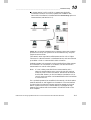
2.6 Network considerations
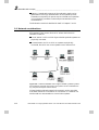
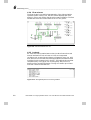
Figure 2-6 illustrates how a networked UNICORN OS installation can
be organized. There are two kinds of PC where UNICORN OS
software is installed:
A local station is a PC to which oligonucleotide synthesis systems are
physically connected.
A remote station is a PC to which no systems are physically
connected, but which can control systems over a network link.
Figure 2-6. A network installation with 3 oligonucleotide synthesis systems
and 5 stations (3 remote and 2 local). The systems can be controlled from
any computer except the network server.
Oligonucleotide synthesis systems in the network can be controlled
from either remote or local stations. A local station in a network can
also be used as a remote station to control other systems.
2-12
UNICORN for Oligo Synthesis version 1.10 User Manual 18-1118-52 Edition AA
________________________________________________ UNICORN OS concepts
Note:
2
If a run is being controlled from a remote station and a
network communication error occurs, the run will continue
under the control of the local station. Results will be saved in
the FAILED directory on the local station (see Section 6.4). A
control mode connection can be established on the local station
to control the run.
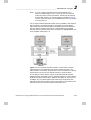
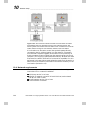
For an oligonucleotide synthesis system to be accessible in the network,
the local station must be switched on and logged in to the network.
UNICORN OS user interface does not however need to be started on
the local station. System control from a remote station is managed
through network level routines which are started in startup.cmd on the
local computer (see Figure 2-7).
Figure 2-7. The connection interface module in a local station is started
automatically and runs separately from the user interface module. This
allows systems connected to the local station to be controlled from a remote
station without running the user interface module on the local station.
A local station can be used to control the oligonucleotide synthesis
systems directly connected to the PC without logging in to the network.
Method and result files stored on network drives will of course not be
accessible. For runs performed in this stand-alone mode where the
result file is directed to a network drive, the results will be saved in the
FAILED directory on the local station (see Section 6.4).
UNICORN for Oligo Synthesis version 1.10 User Manual 18-1118-52 Edition AA
2-13
2
UNICORN OS concepts _________________________________________________
2.7 Security
Security features in UNICORN OS include:
Access security. Use of UNICORN OS is restricted to authorized
users. Each user is assigned an access level which defines the
functions that the user is permitted to use.
Connection security. Running systems may only be controlled from
one connection. Systems may be locked with a password to prevent
other users from changing run parameters.
Data security. Result files can be saved automatically at pre-set
intervals during a run to minimize data loss in the event of system
failure. In a network installation, results are saved on the local
station if network communication fails.
Security features are discussed in more detail in Chapter 9. Network
and administrative aspects are discussed in Chapters 10 and 11
respectively.
2-14
UNICORN for Oligo Synthesis version 1.10 User Manual 18-1118-52 Edition AA
__________________________________________________Login and file handling
3
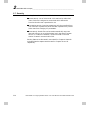
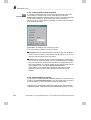
3. Login and file handling
3.1 Logging in
To start UNICORN OS, double-click on the UNICORN OS icon on
the OS/2 desktop. The program takes a little while to start.
Desktop icon
If UNICORN OS is already started and the previous user has logged
out, click on the Login button at the bottom of the UNICORN OS
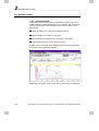
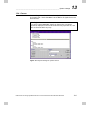
desktop.
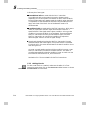
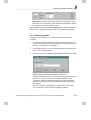
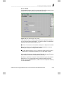
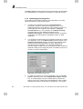
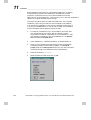
Figure 3-1. The Login Menu dialogue box.
Click on your username in the list or type the name directly in User
field. Type your password in the Password field and then click on the
OK button to log in.
If you cannot remember your password, you cannot log in to
UNICORN OS. Ask your system administrator or other user with
sufficient authorization to give you a new password.
Press the Cancel button to abandon the log-in attempt. If you press
Cancel during initial start-up of UNICORN OS, the system returns to
the OS/2 desktop.
Network installations
In a network installation, you must log in to the network before
starting UNICORN OS.
If you want to control a system from the local computer without
logging in to the network, press Enter when the startup.cmd window
appears. Do not just minimize or close the startup.cmd window.
You can log in to UNICORN OS on any computer in the network,
provided that UNICORN OS software is installed on that computer.
You can log in with the same username and password on any number
UNICORN for Oligo Synthesis version 1.10 User Manual 18-1118-52 Edition AA
3-1
3
Login and file handling _________________________________________________
of computers simultaneously. All computers can connect to and display
a running system, but a given system can only be actively controlled
from one computer. Multiple log-ins with the same username are
treated internally as separate users for the purpose of System control.
Note:
Do not confuse network log-in with UNICORN OS log-in.
You log in to the network to gain access to network resources
(shared drives, printers and other networked equipment). You
log in to UNICORN OS to gain access to the oligonucleotide
synthesis systems that are installed in the network. The
username and password for logging in to the network are
entirely independent of the those for logging in to UNICORN
OS.
3.2 UNICORN OS desktop
3.2.1 Icons and windows
Each of the four modules in UNICORN OS is represented by an icon
or an open window on UNICORN OS desktop (see Figure 3-2). On
start-up, the Main menu is presented as a window and the other
modules as icons. There may be several icons for System control,
according to how the program was installed. There is however only one
icon for the Main menu, Method editor and Evaluation module.
Figure 3-2. UNICORN OS desktop with the Main menu active.
3-2
UNICORN for Oligo Synthesis version 1.10 User Manual 18-1118-52 Edition AA
__________________________________________________Login and file handling
3
To expand a module to a window, double-click on the corresponding
icon. If User:Autominimize is checked in the Main menu, only one
window can be expanded at once, and expanding one icon to a
window automatically minimizes the previously active window. If
User:Autominimize is not checked, any number of windows can be
expanded at the same time. You can drag window borders to adjust the
size of module windows (and of panels and windows within the module
windows).
To minimize a window to an icon, click on the Minimize button at the
right-hand end of the window title-bar. Depending on how UNICORN
OS is installed (see Section 11.4), you may also be able to minimize
UNICORN OS window to an icon on the OS/2 desktop.
Note:
Minimizing a module window to an icon does not close the
module. Once opened, UNICORN OS modules remain open
until you quit the program. A minimized System control icon
may thus be actively in control of a running process.
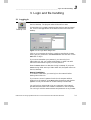
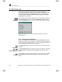
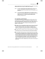
3.2.2 UNICORN OS Main menu panels
The two Main menu panels display method and result files respectively.
Use the panels as follows:
Click anywhere in the panel (outside an icon or file name) with the
right mouse button to pull down a menu for setting the panel
presentation.
Click on an icon or file name with the right mouse button to pull
down a menu for opening, copying, moving, renaming or deleting the
file. Method files can also be opened for either System control (Run)
or editing (Edit) from this menu.
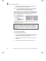
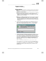
Figure 3-3. The Methods panel showing pull-down menus for panel
presentation (left) and file management (right)
UNICORN for Oligo Synthesis version 1.10 User Manual 18-1118-52 Edition AA
3-3
3
Login and file handling _________________________________________________
Alternatively, double-click on an icon to open the file. For method
files, this opens the file in the Method editor. For result files, this
opens the file in the Evaluation module.
Select a method file and click on Run or Edit to run or edit the
method respectively.
To change the size of a panel, drag the panel border. Click on the
Maximize button at the right-hand end of the panel title bar to toggle
panel size between normal and maximized. (Maximizing a panel will
hide but not close the other panel.)
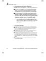
3.2.3 Presenting files
The way files are presented in the panel can be set from the File menu
or from the pull-down menu that appears when you click with the right
mouse button in the panel. Presentation options are
view mode (icons or detail display)
sorting order
filter (for displaying only a chosen set of objects, e.g. methods for one
system)
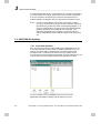
View
You can display the contents of the panels either as graphical icons
(View:Icons) or as a details list (View:Details). The details list includes a
small icon identifying the type of object, file size, last written date and
time and creation date and time.
To change the view mode, choose View from the pull-down panel menu
or from the File menu, and choose the appropriate mode from the submenu.
3-4
UNICORN for Oligo Synthesis version 1.10 User Manual 18-1118-52 Edition AA
__________________________________________________Login and file handling
3
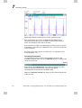
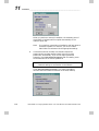
Figure 3-4. Icon and detail display modes illustrated for the methods panel.
Sort
Files can be sorted in the panel according to one of
name (alphabetical order)
type (directories and files)
size (smallest files first)
creation date (oldest files first)
last saved date (least recently modified files first)
To change the sorting order, choose Sort from the pull-down panel
menu or from the File menu, and choose the appropriate sorting order
from the sub-menu. Changing the sorting order affects only the
currently active panel.
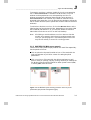
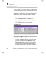
Filter
To restrict the files displayed according to file name or the system with
which they are associated, choose Filter from the pull-down panel menu
or from the File menu. Mark the system(s) for which you want to
display files, and enter a file name specification if required. Click on OK
to activate the filter. The filter affects the display in both panels.
UNICORN for Oligo Synthesis version 1.10 User Manual 18-1118-52 Edition AA
3-5
3
Login and file handling _________________________________________________
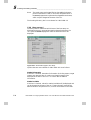
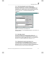
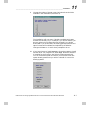
Figure 3-5. The Filter dialogue box.
You can use standard OS/2 wildcard characters in the file name
specification (* stands for any number of characters, ? for any single
character). For example:
test
will display only files named test
test*
will display all files with names beginning with test
*test
will display all files with names ending with test
?test
will display only 5-character names ending with test
If a filter is active, this is indicated in the title bar of the panel (e.g.
Results : filtered igf*). To display all files, choose Filter and click on
View All.
3-6
UNICORN for Oligo Synthesis version 1.10 User Manual 18-1118-52 Edition AA
__________________________________________________Login and file handling
3
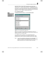
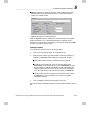
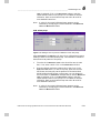
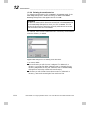
3.2.4 Finding files
To find a file:
1.
Choose Find from the pull-down panel menu or from the File
menu. Enter a file name specification in the Search for field.
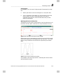
Figure 3-6. The Find dialogue box.
You can use standard OS/2 wildcard characters in the file name
specification (see above).
2.
You can restrict the search further if required:
Choose file type from the pull-down menu for Type (All,
Directory, Method or Sequence for the methods panel; All,
Directory, Result or Sequence/Scouting for the results panel).
Click on Date Range for files last written between specified
dates.
Check Search all directories to search through all the directories
to which you have access. If Search all directories is not
checked, the search will be restricted to the current directory and
sub-directories below.
3.
Click on Search when you have entered all parameters. The result
of the search is shown in the Found item box.
UNICORN for Oligo Synthesis version 1.10 User Manual 18-1118-52 Edition AA
3-7
3
Login and file handling _________________________________________________
4.
Double-click on a file in this list to return to the Main menu with
the selected file highlighted in the appropriate panel. If you click
on Exit (with or without selecting a file), you will return to the
Main menu with the panel display unchanged.
3.2.5 Copying, moving and renaming files
You can copy, move or rename files and directories using commands
from the pull-down file menu or from the Main menu bar. If you copy
or move directories, all files within the directories will also be copied or
moved.
1.
Select one or more files in the Methods or Results panel of the
Main menu. To select multiple files, hold down the <Ctrl> key
while you click on the file names or icons. (Rename is not
available if you select multiple files.)
2.
Click with the right mouse button on any file icon and choose the
appropriate command from the pull-down file menu, or choose
the command from the File menu in the Main menu bar.
3.
For Copy and Move, choose the directory to which you want to
copy the file and click on OK. For Rename, enter a new name for
the file or directory.
Notes: To copy or move a method or result file to a diskette, choose
the a: folder as the target directory. A file that has been stored
on a diskette cannot be opened directly from the diskette. To
use a file from a diskette, first copy the file back to an
appropriate folder on the hard disk.
To copy a file within the same directory, use the File:Save as
command in the appropriate module after opening the file. The
copy must have a different name from the original.
You cannot copy or move files between the Methods and
Results panels of the Main menu.
Explicit authorization is required to copy or move files (see
Chapter 9).
3-8
UNICORN for Oligo Synthesis version 1.10 User Manual 18-1118-52 Edition AA
__________________________________________________Login and file handling
3
3.2.6 Deleting files
To delete a file or directory:
1.
2.
Select the item(s) to be deleted in the Methods or Results panel of
the Main menu. To select multiple files, hold down the <Ctrl> key
while you click on the file names or icons.
Click with the right mouse button on any file icon and choose
Delete from the pull-down file menu, or choose Delete from the
File menu in the Main menu bar.
3.
Confirm the deletion in the dialogue box.
Notes: Home directories cannot be deleted by this method (see
Chapter 12).
Explicit authorization is required to delete files (see Chapter
12).
A file that has been deleted cannot be recovered except by
restoring a back-up copy or using a third-party utility for
recovering lost files.
3.2.7 Backup security
To protect important data against accidental deletion or loss in the
event of hard disk failure, backup copies should be taken at regular
intervals. To make back-up copies, you can either copy files to diskette
using the File:Copy command in UNICORN OS (choose the a: folder
as the target diskette for the copy operation), or use OS/2 backup
functions from the OS/2 Workplace Shell. A tape streamer is however
recommended for efficient backup handling from OS/2. If you are
working in a network, you can copy files to the network server (make
sure that the network administrator runs server back-ups regularly).
Backup copies should be stored in a safe place, physically separated
from the PC.
The responsibility for making backup copies rests entirely with the
user. Amersham Biosciences cannot undertake to replace method programs lost as a
result of computer failure or other incident.
UNICORN for Oligo Synthesis version 1.10 User Manual 18-1118-52 Edition AA
3-9
3
Login and file handling _________________________________________________
3.3 Logging out
To log out of UNICORN OS, press function key F12 or click on the
Logout button at the bottom of UNICORN OS desktop.
Processes that are running when you log out will continue to run, and
may be left locked with a locking password or unlocked (see Section
6.5 for more details). Any modules that were active at the time of logout (e.g. unsaved methods or evaluation sessions) will be re-opened
when the same user logs in again.
UNICORN OS will still be open after a user has logged out, and
another user may log in. We recommend that you always log out when
you leave the computer, to prevent other users from accidentally
changing or deleting your files or disturbing your runs.
3.4 Quitting UNICORN OS
To quit UNICORN OS and close the program, choose File:Quit
program or Quit:Quit program from the Main menu. You will be
prompted to save any unsaved work in the Method editor or
Evaluation module. You can only quit the program from the Main
menu.
Note:
3-10
You can quit UNICORN OS during a run which does not use
scouting or a sequence without affecting the run. Do not
however shut down OS/2 or turn off the computer while the
run is in progress.
UNICORN for Oligo Synthesis version 1.10 User Manual 18-1118-52 Edition AA
Introductory material
Methods and Runs
Evaluation
System management
Appendices
This page is deliberately left blank.
__________________________________ Creating methods from method templates
4
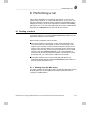
4. Creating methods from method
templates
UNICORN OS is supplied with a set of method templates which are
used as the starting point for creating customized methods. These
method templates are defined with variables for critical parameters in
the synthesis, so that customized methods can be created for most
purposes simply by setting appropriate values for the method variables.
This chapter describes how to create and edit methods at this level. See
Chapter 5 for a description of advanced method editing facilities.
Briefly, the steps in creating a method by editing method variables are
as follows:
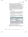
1.
Choose New:Method in the Main menu or the Method editor and
select a system and template.
2.
Choose View:Run setup or press the Run setup button.
3.
Open the Sequence page and enter the desired sequence and create
the method. Click on the Save As button in the Sequence page if
the sequence should be saved for future use.
4.
Enter the method variables.
5.
Read the method notes.
6.
Save the method.
7.
Run the method
UNICORN for Oligo Synthesis version 1.10 User Manual 18-1118-52 Edition AA
4-1
4
Creating methods from method templates __________________________________
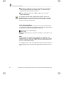
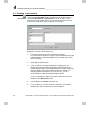
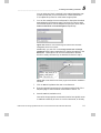
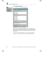
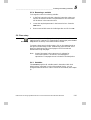
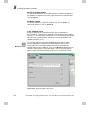
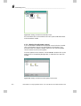
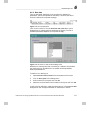
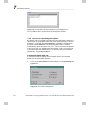
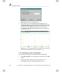
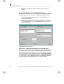
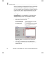
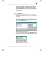
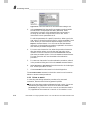
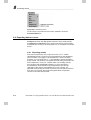
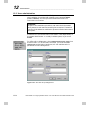
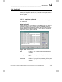
4.1 Creating a new method
New method
To create a new method, click on the New Method toolbar button or
choose the File:New:Method menu command in the Method editor, or
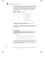
choose File:New:Method or New:Method in the Main menu. These
alternatives are equivalent. When you choose the command from the
Main menu, the Method editor is opened automatically.
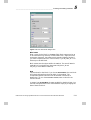
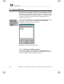
Figure 4-1. The New method dialogue box.
1.
Choose the system for which the method is intended.
The instructions available for a given system are determined by the
system strategy. A method developed for one system may not be
valid on another.
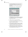
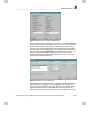
2.
Select Any as the technique.
3.
A list of ready-to-run method templates is displayed for the
selected technique. Available templates are determined by the
system strategy. Select one of these templates to create customized
methods either by adjusting variable values (see Chapter 4) or
changing method instructions. For your first run, you are
recommended to select the method template, fixrec.
Click on a template to display information about the particular
template in the Method notes field.
4-2
4.
Choose Any in the Column pull-down list.
5.
Click on OK once you have made your selections. The method
template will now be opened as an untitled method.
UNICORN for Oligo Synthesis version 1.10 User Manual 18-1118-52 Edition AA
__________________________________ Creating methods from method templates
4
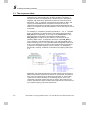
4.2 Saving and running a test sequence method
All newly created templates already contain a partially built method for
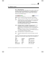
a pre-defined 20 base sequence, which is:
5´ ATA CCG ATT AAG CGA AGT TT 3´
This sequence can be viewed in the sequence editor in the Sequence
page of Run setup, or the blocks for the sequence as blocks in the Text
instruction panel. This partial method has two main uses:
Used specifically with the fixrec method template, you can save the
method and directly perform a test run of UNICORN OS to
synthesize the sequence (see below)
Used with any method template, you can replace the supplied
sequence with a sequence of your own choice and then generate a
ready-to-run method for that sequence (see Section 4.3).
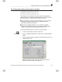
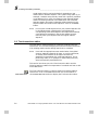
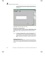
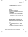
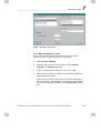
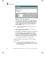
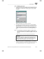
To use the 20 base sequence for a test run of the instrument:
1.
Run setup
2.
Create a new method according to Section 4.1.
Click on the Run set-up button on the toolbar or select View:Run
setup.
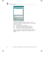
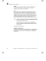
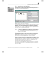
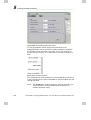
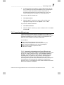
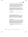
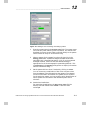
3.
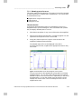
Select the Sequence page to display the pre-defined sequence in the
sequence editor field.
Figure 4-2. Sequence page in Run setup containing the 20 base
sequence pre-defined in the method template.
UNICORN for Oligo Synthesis version 1.10 User Manual 18-1118-52 Edition AA
4-3
4
Creating methods from method templates __________________________________
3.
Click on the Create button (see Section 4.3), which fully generates
the method and inserts default variable values. The Save As
dialogue is then displayed. Save the method with the name test20.
The method must be saved before you can make a run. The test20
method will be displayed in the Methods box of the Main menu.
4.
To run the test20 method, follow the instructions detailed in
Section 4.7 and Chapter 6. You can change the method variables
prior to the commencement of the run.
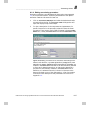
4.3 Creating a sequence and method
As described in Section 4.2, all of the method templates contain a
partially built method for a pre-defined 20 base sequence. By replacing
the pre-defined sequence with a sequence of your choice, you can
quickly and easily create a ready-to-run method.
1.
2.
Select a method template in the New Method dialogue box, as
described in Section 4.1.
Click on the Run set-up button on the toolbar or select View:Run
setup.
3.
Select the Sequence page to display the pre-defined sequence.
Select the pre-defined sequence in the sequence editor and delete it
using the <Delete> key on the keyboard.
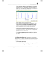
4.
Enter a new sequence, up to a maximum of 200 bases, in the
sequence editor in the 5´-3´ direction. Remember that the synthesis
always proceeds in the reverse direction, i.e. 3´-5´ direction. By
default, a DNA sequence consisting of oxidated bases taken from
the standard reagent positions, is created. This is evident by the
default selected radio buttons.
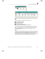
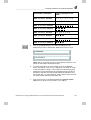
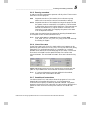
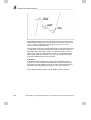
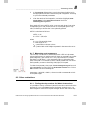
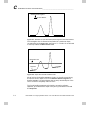
Figure 4-3. Radio buttons in the Sequence page used for choosing the
base type to be included in the sequence.
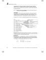
By changing the radio button combination, you can freely change
the component bases contained within the sequence. You are able
to select DNA or RNA, whether the base is oxidated or thiolated,
and whether the base is taken from the standard or modified
reagent position. There are two extra physical reagent positions in
OligoPilot II, labelled X and Y. The extra characters Z and Q are
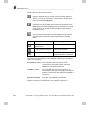
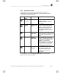
also provided. The available combinations are as follows:
4-4
UNICORN for Oligo Synthesis version 1.10 User Manual 18-1118-52 Edition AA
__________________________________ Creating methods from method templates
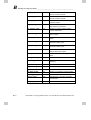
5.
Radio button combination
Bases as represented on the
screen
DNA, -O(xidated), Standard
A, C, G, T, X, Y, Z, Q
DNA, -O(xidated), Modified
A, C, G, T
DNA, -S (thiolated), Standard
A, C, G, T, X, Y, Z, Q
DNA, -S (thiolated), Modified
A, C, G, T
RNA, -O(xidated), Standard
a, c, g, u, x, y, z, q
RNA, -O(xidated), Modified
a, c, g, u
RNA, -S (thiolated), Standard
a, c, g, u, x, y, z, q
RNA, -S (thiolated), Modified
a, c, g, u
4
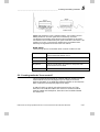
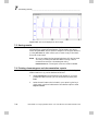
Click on the Group button if you want the sequence to be
displayed in groups of three bases, beginning from the 5´ end.
Figure 4-4. An ungrouped (top) and grouped (bottom) sequence in the
sequence editor field of the Sequence page.
6.
To save the sequence you have created, click on the Save As
button and type in a name for you sequence. The name can be up
to 256 characters in length. Click on OK. The name of the saved
sequence will now be displayed in the Sequence page containing
the specific sequence. Note that saved sequences are personal to
the current user, i.e. users logged in under a specific username will
not see the saved sequences of another user.
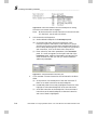
7.
Place a check mark in those boxes beside the Optional method
steps that you want to be included in your method.
UNICORN for Oligo Synthesis version 1.10 User Manual 18-1118-52 Edition AA
4-5
4
Creating methods from method templates __________________________________
8.
Create the method for the sequence you have entered by clicking
on the Create button. The Create button serves four main
purposes:
to check the sequence for invalid combinations (ignoring the 3´
base), e.g. it is not possible to include both base ‘A’ (DNA) and
base ‘a’ (RNA) in the same sequence since they both take up
the same reagent bottle position on the instrument.
to generate a method based on the sequence and crossreference list (see Section 5.1.1).
update the method variables based on the generated method.
display the Save As dialogue so that the method can be saved
before performing a run.
Enter a name for the method, select the destination and click on
OK (see Section 4.6 for more details). The method is saved with
default values for the method variables. These can later be
changed before you start a run (see Section 4.7 and Chapter 6) or
you can change the variables and save the method under a new
name.
Note:
Users with the appropriate access authorization have global
access to methods created by all users. In such circumstances,
an already saved method can be used as the basis for
generating a new method with a different sequence. This is
particularly useful if, for example, a method was saved with
specially modified blocks (see Section 5.2) or cross-reference
lists (see Section 5.1.1).
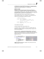
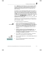
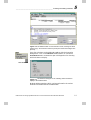
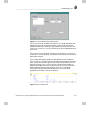
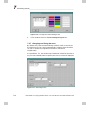
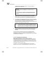
4.4 Editing method variables
Having created a method, you may want to change the default values
for the method variables. The method templates contain all the blocks
that are likely to be needed for a typical synthesis run. By defining a
sequence and then creating a method, the program automatically builds
up a method to synthesize the specific sequence by copying in all of the
relevant blocks from the method template.
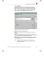
Each block has a set of method variables, displayed on the Variables
page in Run setup. You set default values for the variables in the
Method editor, and can change these values for a particular run when
the run is started.
4-6
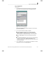
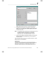
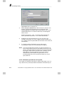
1.
After you have created your method (see Section 4.3), select the
Variables page in Run setup.
2.
Work through the variable list, adjusting the values to suit your
synthesis. To change a variable value, simply type the required
value in the field. Remember that the values you enter here will be
default values, suggested each time the method is run.
UNICORN for Oligo Synthesis version 1.10 User Manual 18-1118-52 Edition AA
__________________________________ Creating methods from method templates
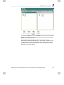
4
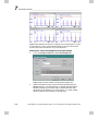
Figure 4-5. The Variables page in Run setup.
If the whole variable list does not fit on one screen, a scroll bar
(see Figure 4-5) will be shown to the right of the list. Click on the
arrows at the ends of the bar to scroll one variable at a time, or on
the bar itself to scroll one screen at a time. You can also drag the
slider button to scroll, but this is not recommended since you can
easily miss variables by scrolling too far.
Figure 4-6. Scroll bar functions.
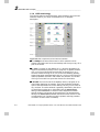
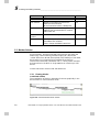
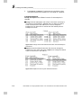
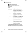
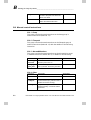
Typical variables are illustrated with the list below, taken from a
method created for OligoPilot II with the fixrec method template. The
list is organized according to the order of the blocks in the method.
Other method templates may vary in their structure and variables.
UNICORN for Oligo Synthesis version 1.10 User Manual 18-1118-52 Edition AA
4-7
4
Creating methods from method templates __________________________________
Start_parameters
These variables together define the synthesis scale, i.e. Weight of the
support, Loading of the support and Column diameter. CV (column
volume) is also defined and is used for the calculation of special
instructions such as Vol_Cap, Vol_amid and CT5_Cap.
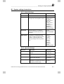
CV_column_wash
The number of column volumes (CV) to wash the column is set here.
If zero is entered, no wash will take place.
Detrit_peak_start
The flow rate of the detritylation solution is set here.
Detrit_wash
The pressure of the detritylation wash and the number of column
volumes of detritylation solution to be used are set here.
DNA_Parameters
These variables together define the coupling of a base to the
oligonucleotide sequence, i.e. how many equivalents of amidite
should be added to the column with respect to the scale, the
percentage volume of tetrazole to be used with respect to column
volumes and the concentration of the amidite.
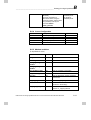
DNA_Recycle
The amidite recycling flow rate and time used are set here.
Oxidation_DNA
Oxidation stabilizes the phosphite group of the coupled amidite. The
variables determine how many equivalents of iodine are used in the
oxidation solution and the contact time between the oxidation
solution and the support.
Capping
The unreacted 5´-hydroxyl groups on the oligonucleotide are capped
to prevent further participation in the synthesis reaction. The column
volumes of capping solution and the contact time are set here.
Note:
4-8
The base for the all the blocks in the method templates, unless
otherwise stated in the specific block, is column volume. To
use absolute volume or time as the method base, change the
Base instruction in the Main block using the text instruction
editor. See Chapter 5 for a description of how to do this.
UNICORN for Oligo Synthesis version 1.10 User Manual 18-1118-52 Edition AA
__________________________________ Creating methods from method templates
4
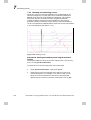
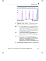
You can get a graphical view of the length of the blocks in a method as
follows:
1.
Click on the Text instructions button on the toolbar.
2.
Click on the Windows button on the toolbar and select only
Graph. The method is now displayed graphically.
3.
Click on the Scale button in the graphical display to select a base
for the graphical display. Changing the display base will not affect
the base in the method.
4.
To return to the Variables page in Run setup, click on the Run
setup button on the toolbar.
Text instructions
Windows
Run setup
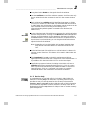
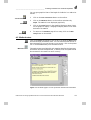
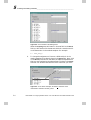
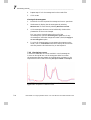
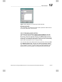
4.5 Method notes
Print
Maximize notes
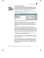
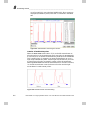
Click on the Notes thumb-tab in the run set-up to show the Notes page,
and read through the method notes. You can maximize each section in
the notes page to fit more of the text on one screen. Click on the printer
icon or choose File:Print to print the method notes.
The method notes provided with each template describe the important
information about the template and, if relevant, how the system should
be connected for the method to work correctly.
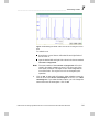
Figure 4-7. The Notes page in run set-up with the method notes maximized.
UNICORN for Oligo Synthesis version 1.10 User Manual 18-1118-52 Edition AA
4-9
4
Creating methods from method templates __________________________________
If your system does not correspond to the description, either rearrange
the valves and tubing connections in accordance with the method notes
description or edit the method instructions (see Chapter 5) in
accordance with your system set-up.
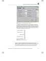
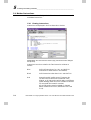
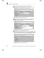
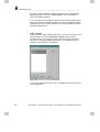
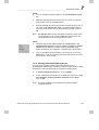
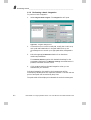
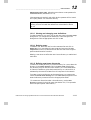
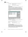
4.6 Saving the method
When you click on the Create button in the Sequence editor page,
UNICORN OS checks the sequence for invalid combinations, generates
the method, updates the method variables and automatically opens the
Save As dialogue box. The method must be saved before it can be run.
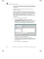
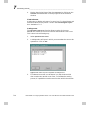
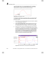
Figure 4-8. Dialogue box for saving a method. The Methods panel will be
shown in icon or detail view according to the current setting in the Main
menu. You can change the display mode from the pull-down menu, activated
by clicking with the right mouse button in the panel (see Section 3.2.3).
4-10
1.
Enter a name for the method. Method names may be up to 8
characters long and may contain letters (A-Z), digits (0-9) and
underscore characters. The case of letters is not significant. The
method name must be unique for the chosen system within the
directory (see steps 2 and 3 below).
2.
By default, the method will be saved in your home directory. To
change the directory, double-click on the appropriate directory
icon in the Methods panel.
3.
If you have more than one system connected to the PC, choose the
system for which the method is intended. The method can only be
run on the system for which it is saved. Remember that different
systems may have different configurations and control capabilities.
4.
Choose the technique for which the method was written.
5.
Click on OK.
UNICORN for Oligo Synthesis version 1.10 User Manual 18-1118-52 Edition AA
__________________________________ Creating methods from method templates
Note:
Save
4
The method templates are written for standard strategies. If
you receive a syntax error message when the method is saved,
one or more instructions in the method are invalid. These may
be calls to blocks which are not defined, or instructions which
are invalid in your customized strategy (this can also arise if a
method is written for one system then saved on another).
Invalid instructions are marked in red in text instruction mode
in the Method editor (see Section 5.4.1), and must be deleted
or replaced before the method can be run.
The method remains open in the Method editor when it has been saved,
so that you can continue editing if you wish. If you edit any of the
method instructions or change the method variables, you can save these
changes by selecting File:Save or clicking on the Save button in the
toolbar. If you want to save a copy of the method under a new name,
choose File:Save As and enter the details as described above. If you
close an open method or the Method editor module and there are
unsaved changes, you will be prompted to save these changes.
4.7 Starting a run
This section briefly summarizes how to start a run with a method. The
method must be named and saved before it can be started. See Chapter
6 for more details of how to run a method.
Note:
If you are editing the method in the Method editor and have
made changes that you have not yet saved, these changes will
not apply during the run. Similarly, if you edit the method
while it is running, the run will not be affected. It is the version
of the method which is saved on disk at the time when the
method is started that controls the run. You are able change
the method variables in the Start Protocol at the beginning of a
run but these will only be valid for the current run and will not
be saved.
1.
Establish a control mode connection to the system where the
method is to be run. See Section 6.5 for details. You cannot start a
method without a control mode connection to the appropriate
system.
2.
Choose File:Run from the System control window for the required
connection and select the method to run. Alternatively, select the
method in the methods panel of the Main menu. (Do not doubleclick on the method icon in the Main menu: this will open the
Method editor.)
3.
Click on Run. This will display the first page of the start protocol.
UNICORN for Oligo Synthesis version 1.10 User Manual 18-1118-52 Edition AA
4-11
4
Creating methods from method templates __________________________________
4.
Change the method variable values if required, such as loading
weight, CV, column volume etc. The suggested values are those
saved in the method. Any changes you make will apply only for
the current run, and will be recorded in the run documentation.
5.
Go through the rest of the start protocol, entering information
where appropriate. Use the Next and Previous buttons to move
through the start protocol. If you click on Cancel on any page in
the start protocol, the method will remain loaded in the System
control module but will not start. Start protocol pages for most
method templates are:
6.
Method
Variables
All the variables defined in the method
instructions, organized by block. Values for
variables can be entered or changed here for the
current run.
Prerun
Questions
Questions are data entry fields which are filled in
by the operator when the run is started. Some
questions may be mandatory and some may
require authorized confirmation.
Notes
Method notes are displayed and start notes can be
entered.
Method
Information
Information about the method being run.
Oligo
synthesis
sequence
The sequence of the oligonucleotide to be
synthesized.
Result
name
changeable
The name of the result file is displayed here. This
page is always displayed, and the name may be
changed if this is permitted in the start protocol.
The last page of the start protocol has a Start button instead of
Next. Click on this button to start the run.
4.8 Editing text instructions
Text instructions
4-12
Methods for most purposes can be created by adjusting the method
variable values as described above. The method is, however, actually
programmed as a series of instructions which use these variables as
parameters. To see and/or change the instructions, click on the Text
instruction button on the Method editor toolbar (or choose View:Text
instructions from the menu). To see an overview of block the structure
and buffer concentration in the method, choose View:Windows:Block
and View:Windows:Graph respectively in the text instruction window
(see Section 5.2).
UNICORN for Oligo Synthesis version 1.10 User Manual 18-1118-52 Edition AA
4
__________________________________ Creating methods from method templates
With the instruction editor, you have complete facilities for designing
and editing your own customized methods. You will also use the
instruction editor for refining and modifying methods based on the
standard templates, e.g.
Changing the method base (column volume, volume or time).
Changing method specifications (if the templates do not suit your
system configuration).
Adding or removing variables.
Adding conditional events (such as starting peak integration when a
certain peak level is detected).
Adding or removing instructions to change the method functionality.
Adding or removing blocks to change the method structure.
To gain an understanding of how method templates are built up and
can be modified, work through Chapter 5, which gives a full
description of method editing facilities.
UNICORN for Oligo Synthesis version 1.10 User Manual 18-1118-52 Edition AA
4-13
4
4-14
Creating methods from method templates __________________________________
UNICORN for Oligo Synthesis version 1.10 User Manual 18-1118-52 Edition AA
____________________________________________ Creating and editing methods
5
5. Creating and editing methods
This chapter describes the complete facilities for creating and editing
methods in UNICORN OS. Refer to Section 2.3 for an overview of
method concepts. For many applications, suitable methods can be
created by changing the default variable values in one of the templates
supplied with UNICORN OS (see Section 4.4).
New methods can also be created using the more advanced editing
facilities. These can be used for:
changing selected instructions in the method templates (e.g. changing
the method base)
adding blocks and instructions (e.g. WATCH instructions)
changing method instructions to adapt to non-standard system
configurations
creating new methods for applications which are not covered by the
templates supplied
Advanced editing facilities can be used at three different levels, with the
level chosen being dependent on the type and extent of method
modifications to be made. These are:
modifications at the sequence editor level, i.e. creating custom
methods by assigning a specific base in the sequence editor to a freely
chosen method block (see Section 5.1).
adding new blocks to an existing method and/or modifying
instructions in existing blocks (see Section 5.2)
writing a new method “from scratch”, i.e. selection of No Template
in the New Method dialogue box (see Section 5.9).
UNICORN for Oligo Synthesis version 1.10 User Manual 18-1118-52 Edition AA
5-1
5
Creating and editing methods____________________________________________
5.1 The sequence editor
The sequence editor in the Sequence page of Run setup is a user
interface which allows methods to be easily created. The bases in a
sequence are each cross referenced to a specific block in the method
template, with each block representing a series of instructions to be
performed. Thus, in entering a sequence into the sequence editor and
clicking on the Create button, the specific blocks that are crossreferenced to the bases are copied from the method template into the
method. The method must be saved before it can be then used to run an
instrument.
For example, in a sequence containing the bases 5´-...CA...3´, the DNA
base A is assigned to a specific block in the method template called
Add_DNA_A. Consequently, by clicking on the Create button in the
Sequence page, the A base in the sequence causes the block
Add_DNA_A to be copied into the method. The next base in the
sequence, DNA base C, is assigned to the block name Add_DNA_C.
Thus, the block cross referenced to base C will next be added to the
method (see Figure 5-1). In the standard method templates, each block
that is cross-referenced to a base is a self-contained set of instructions
to perform a complete coupling cycle of one base, i.e. detritylation,
detrit wash, coupling, oxidation or thiolation and capping (see Figure
5-1).
Figure 5-1. The relationship between the bases entered into the sequence
editor and the blocks copied into the method. In the example, the sequence
base A is cross referenced to the block name Add_DNA_A, which is then
copied into the method. Similarly for the following base C, this is cross
referenced to the block named Add_DNA_C which is also copied into the
method. Note that each block contains a self-contained set of instructions for
the complete coupling cycle of the specific base.
5-2
UNICORN for Oligo Synthesis version 1.10 User Manual 18-1118-52 Edition AA
____________________________________________ Creating and editing methods
5
5.1.1 Modifying cross references in the sequence editor
Cross referencing a base to a method template block lends much
flexibility to modifying the method creation process. UNICORN OS
allows the user to change the block that is cross-referenced to any
specific base type.
For example, you may decide that the DNA sequence 5´-ACTGGT-3´
should have a column wash step after the addition of each base in the
sequence. By cross referencing a base not used in the current sequence,
e.g. A, to the column wash block in the method template, this can be
directly incorporated into the sequence to signal a column wash. Thus,
in the sequence 5´-AAACATAGAGAT-3´, the appearance of A does not
mean that a thiolated DNA-A base will be added to the
oligonucleotide, but rather a column wash procedure is performed after
the addition of the preceding base.
Alternatively, you may modify the instructions in an existing block or
create a new block. It is thus a straightforward task to assign the new
block to the base in question.
To change the assignment, do the following:
1.
Create a new method by clicking on the New Method toolbar
button or choose the File:New:Method menu command in the
Method editor, or by choosing File:New:Method or New:Method in
the Main menu. These alternatives are equivalent. When you
choose the command from the Main menu, the Method editor is
opened automatically. The New Method dialogue box will be
displayed.
2.
Choose the system for which the method is intended, e.g.
OligoPilot or OligoProcess. From the Technique pull-down list,
select OligoPilot II or OligoProcess. Next, select one of the
available method templates in the Template pull-down list. Finally,
choose Any in the Column pull-down list.
3.
Click on OK once you have made your selections. The method
template will now be opened as an untitled method.
4.
Click on the Run setup button or select View:Run setup. Select the
Sequence page.
5.
Click on the Cross references button to display the Cross
reference list dialogue box.
New method
UNICORN for Oligo Synthesis version 1.10 User Manual 18-1118-52 Edition AA
5-3
5
Creating and editing methods____________________________________________
Figure 5-2. Cross reference list dialogue box.
Select the Coupling list radio button in the List field. In the Block
field you will see the all the bases and the block name that each is
cross referenced to in the method template. For example:
A = Add_DNA_A
6.
To change the assignment of a base to a different block in the
method template, first select the base in the Block field. Next, click
on the Block pull-down list and select the method template block
that you want assigned to the selected base. The base in the Block
field will now be associated with the block name that you chose.
Figure 5-3. In the above example, the base A has been cross
referenced to the block Column_wash.
5-4
UNICORN for Oligo Synthesis version 1.10 User Manual 18-1118-52 Edition AA
____________________________________________ Creating and editing methods
5
You can select any block contained in the method template, even
including those that you have modified or created (see Section
5.3). Repeat this process for other bases as appropriate.
7.
You can also reassign the cross references for the optional method
steps selected in the Sequence page. The blocks for column wash
and final detritylation can be assigned using the pull down lists for
Column wash block and Final Detriylation respectively.
Figure 5-4. Fields for cross referencing the column wash and final
detritylation blocks in a method.
Additionally, you can click on the Purge solvent list and Purge
amidite list radio buttons respectively to display the options in the
Block field. These options can be cross referenced to different
blocks in exactly the same way as described for bases in step 5.
Figure 5-5. Cross reference list of the purge solvent blocks available in
a method.
7.
Click on Exit to implement the new cross references.
8.
Enter the appropriate sequence in the sequence editor field of the
Sequence page. Create a method as described in Section 4.2.
9.
Save the method (see Section 4.6).
Users with the appropriate access authorization have global access
to methods created by all users. In such circumstances, an already
UNICORN for Oligo Synthesis version 1.10 User Manual 18-1118-52 Edition AA
5-5
5
Creating and editing methods____________________________________________
saved method can be used as the basis for generating a new
method with a different sequence. This is particularly useful if, for
example, a method was previously saved with a specially modified
cross-reference list. In such circumstances, open the appropriate
method containing modified cross-reference list and access the
Sequence page in Run setup. Delete the existing sequence in the
sequence editor and enter the new sequence. Click on the Create
button.
Note:
Do not open a saved sequence from your personal sequence list
in the Sequence page, otherwise the cross-reference list
corresponding to the saved sequence will replace the modified
cross-reference list present in the current method. Always
manually enter your sequence over the original method
sequence.
5.2 Text instructions editor
The next level of advanced editing to create new methods uses Text
instructions. This involves modifying the instructions within the blocks
of an existing method and/or adding new blocks to a method.
Note:
Users with the appropriate access authorization have global
access to methods created by all users. In such circumstances,
an already saved method can be used as the basis for
generating a new method with a different sequence. This is
particularly useful if, for example, a method was previously
saved with specially modified blocks.
This section introduces you to the Text instruction editor and the
following sections present the components of a method and how to edit
and create blocks.
Text instructions
5-6
The Text instruction editor is used for entering and editing method
instructions. Click on the Text instructions icon on the toolbar or
choose View:Text Instructions to display the Text instruction editor.
UNICORN for Oligo Synthesis version 1.10 User Manual 18-1118-52 Edition AA
____________________________________________ Creating and editing methods
5
Figure 5-6. The Method editor in Text instruction mode, showing the block
window (top), Text instruction window (centre) and instruction dialogue box
(bottom).
Up to four windows can be displayed together with the instruction
dialogue box. Click on the Windows toolbar button or choose the
View:Windows menu command to open a dialogue box for choosing
which windows to display.
View windows
Figure 5-7. The Windows dialogue box for selecting which windows to
display in the Method editor.
Method editing operations which can be performed in the various
windows are summarized in the table below.
UNICORN for Oligo Synthesis version 1.10 User Manual 18-1118-52 Edition AA
5-7
5
Creating and editing methods____________________________________________
Window
Operations
See Section
Block window
Select block.
5.3
Text window
Display and hide block instructions.
Select current instruction
Move instructions within a breakpoint.
5.4
Graph window
Display block durations throughout the
method. Not recommended for use with
UNICORN OS.
-
Flow scheme
window
For information only.
5.4.5
Instruction box
Specify breakpoints, instructions,
parameters and variables.
Insert, change and delete instructions.
5.4.2 - 5.4.4
5.3 Method blocks
Method blocks represent “modules” in the structure of the method.
Most commonly, each block handles one functional unit within the
method (e.g. column washing, amidite coupling etc.). Blocks are
“called” either from MAIN (the top level of the method) or from other
blocks using CALL instructions (unconditional) or WATCH
instructions (conditional) (see Section 5.8.7). Calling a block executes
the instructions in the block. A single method can contain up to 250
blocks.
Use text instruction mode to view and edit blocks.
5.3.1 Viewing blocks
In the block window
The organization of blocks in the method is shown graphically in the
block window in Text instruction mode.
Figure 5-8. The Method editor block window.
5-8
UNICORN for Oligo Synthesis version 1.10 User Manual 18-1118-52 Edition AA
____________________________________________ Creating and editing methods
5
Each block is represented by a grey line with the block name and the
length of the block. The line is shifted down to indicate calls to other
blocks. In the example above, the blocks are called in sequence from
the Main block at breakpoint 0. Blocks to which there is no valid call
are not shown in this window.
Conditional (WATCH) instructions are indicated by a green line
showing the start and duration of the watch.
In the Text instruction window
In the text instruction window, each block is represented by a CALL or
WATCH instruction in blue text. Double-click on the blue instruction
to show the instructions in the called block (see Section 5.4.1). If you
click on the line representing a block in the block window, the first
instruction in the block will be highlighted in the text window.
5.3.2 Calling blocks
Blocks are activated in a method with the CALL instruction. A call to a
block passes process control to the instructions in the block: when the
block either finishes or executes an END_BLOCK instruction, control
returns to the point from which the call was made.
Figure 5-9. Illustration of the flow of process control through method blocks.
UNICORN for Oligo Synthesis version 1.10 User Manual 18-1118-52 Edition AA
5-9
5
Creating and editing methods____________________________________________
Calls may be of two types:
Unconditional calls are made with the CALL instruction.
Unconditional calls can be made in Normal or Restore mode,
depending on how the system is to behave on return from the block.
Normal mode retains any settings made in the block when the block
is completed, so that the method continues using the settings which
apply at the end of the block. Use of the Restore mode is not
recommended.
Conditional calls are made with a WATCH instruction, which sets a
watch on a particular monitor signal and transfers control to a
specified block if the signal meets a given condition. As long as the
condition is not met, the block is not activated. There are different
WATCH instructions for each process monitor signal, and each
WATCH instruction can use various conditions to respond to
absolute signal values or to rate of signal change.
Note that the breakpoint when the WATCH instruction is issued
determines when the watch begins, not when the block is activated.
The block will in fact never be activated if the watch condition is not
met during the run.
Once set, a watch remains active until the condition is met or a new
WATCH instruction is issued for the same monitor. The watch is
cancelled automatically when the condition is met. A watch can also
be turned off with the WATCH_OFF instruction.
See Section 5.8.7 for more details of WATCH instructions.
5.3.3 Adding blocks
‘
New block
5-10
To add a new block to a method, make sure the editor is in Text
instruction mode, then click on the New block toolbar button or choose
File:New:Block from the menu.
UNICORN for Oligo Synthesis version 1.10 User Manual 18-1118-52 Edition AA
____________________________________________ Creating and editing methods
5
Figure 5-10. The New block dialogue box.
Block name
Enter a name for the block in the Name field. Block names may be up
to 30 characters long, and may contain letters (A-Z), digits (0-9) and
underscore characters. Use underscore characters instead of spaces if
you want to separate words in a block name, e.g. Add_DNA_W. This
field may not be left blank.
Block names must be unique within the method. The case of letters is
retained but is not significant (the names Add_DNA_W and
add_dna_w are treated as identical).
Base
Choose a base for the block. If you choose SameAsMain, the new block
will inherit the base from the Main block in the method. The
corresponding BASE instruction will be inserted in the block at
breakpoint 0. If you choose Column volume, enter a value for the
column volume.
In general, use SameAsMain wherever possible for the block base. You
can then change the base of the whole method simply by changing the
base of the Main block.
UNICORN for Oligo Synthesis version 1.10 User Manual 18-1118-52 Edition AA
5-11
5
Creating and editing methods____________________________________________
Length
You can enter a length for the block if required. An END_BLOCK
instruction will be inserted in the block at the corresponding
breakpoint. This field may not be left blank.
Call
You can create a CALL instruction to call the new block from an
existing block (e.g. the Main block). Choose the block in which the
CALL instruction is to be inserted in the From field and enter the
breakpoint at which the CALL is to be made in the At field. If you do
not want to create a CALL instruction (e.g. when the block being
created is to be activated by a WATCH instruction), choose an empty
line in the From field. Blocks which are created without a CALL
instruction are placed last in the method, and the instructions are grey.
Notes: If the CALL instruction is placed at the same breakpoint as the
END_BLOCK instruction, the CALL instruction will be placed
immediately before END_BLOCK.
Do not call a block from within itself. You will generate a
potentially infinite loop, which exceeds the maximum number
of 10 calls allowed in a method. There is no limit for calls
outside a loop.
Press OK to add the new block.
Strategy for creating blocks
For blocks which are to be called unconditionally, it is usually easiest to
create the CALL instruction at the same time as you create the block,
by selecting another block name in the From field in the New block
dialogue box.
5-12
UNICORN for Oligo Synthesis version 1.10 User Manual 18-1118-52 Edition AA
____________________________________________ Creating and editing methods
5
For blocks which are to be called conditionally with a WATCH
instruction, do not create a CALL instruction at the same time as you
create the block. Leave the From field empty in the New block dialogue
box. When you later insert the WATCH instruction in the method, the
new block name will appear in the list of possible actions for the watch.
See Section 5.4.2 for details of inserting instructions.
5.3.4 Deleting blocks
To delete blocks from a method, choose File:Delete Blocks.
Figure 5-11. The Delete blocks dialogue box.
Select one or more blocks to delete and press OK, then confirm or
abandon the deletion. Double-clicking on a block name is equivalent to
selecting the block and pressing OK.
If you delete a block by mistake, you can restore the block by
importing from the saved version of the method (see Section 5.3.6)
provided that you have not saved the method with the block deleted.
Note:
Any CALL or WATCH instructions which call deleted blocks
remain in the method, but are shown in red in the Text
instruction window to indicate that they are no longer valid. A
method cannot be run if it contains invalid instructions.
UNICORN for Oligo Synthesis version 1.10 User Manual 18-1118-52 Edition AA
5-13
5
Creating and editing methods____________________________________________
5.3.5 Renaming blocks
To rename blocks, choose File:Rename block.
Figure 5-12. The Rename blocks dialogue box.
Select the block to rename, enter the new name in the Rename Block
field and press Rename. The dialogue box remains open until you press
Exit, so that you can rename more than one block without closing the
dialogue box.
If the block you renamed is used in a CALL or WATCH instruction,
the block name in these instructions will be changed automatically.
5-14
UNICORN for Oligo Synthesis version 1.10 User Manual 18-1118-52 Edition AA
____________________________________________ Creating and editing methods
5
5.3.6 Importing and copying blocks
You can import blocks from other methods to the method you are
developing. You can also use the import function to copy blocks within
the method. Choose File:Import block as.
Figure 5-13. The Import block dialogue box.
Choose the method from which you wish to import and mark the block
to import. The name of the selected block is suggested in the Import
block as field. Click on Import to import the block. The dialogue box
remains open until you click on Exit, so that you can import more than
one block without closing the dialogue box.
Note:
If you use the import function to copy blocks within a method,
the blocks are copied from the saved version of the method on
disk. Any changes you have made in the method but not yet
saved will not be copied.
The imported block may not have the same name as an existing block
in the method. If the default name is not allowed for this reason, the
Import button will be grey and locked. Change the name of the
imported block so that the Import button becomes available.
The block is imported exactly as it appears in the source method, and is
placed after the last instruction in the text window, unless there is a call
to the imported block already in the method. If any CALL or WATCH
instructions in the imported block refer to non-existent blocks, the
instructions will appear in red in the text window.
If the base of the imported block is defined as SameAsMain, the block
will inherit the main base in the new method, regardless of the base in
the source method.
UNICORN for Oligo Synthesis version 1.10 User Manual 18-1118-52 Edition AA
5-15
5
Creating and editing methods____________________________________________
5.4 Method instructions
Use the instruction dialogue box in Text instruction mode to enter, edit
and delete instructions.
5.4.1 Viewing instructions
Instructions are displayed in the Text instruction window.
Figure 5-14. The Text instruction window (top) with the instruction dialogue
box (bottom).
Instructions are colour-coded in the Text instruction window as
follows:
5-16
Blue
Valid call instructions (i.e. CALL and WATCH
instructions to other blocks in the method).
Black
Valid instructions other than CALL and WATCH.
Red
Instructions with invalid syntax. These may be:
(a) calls to blocks which are not defined in the
method, or (b) instructions which apply to a different
system strategy (these can arise if a method is written
for one system and saved for another).
All red instructions must be deleted or changed
before a method can be run (see Sections 5.4.3 and
5.4.4).
UNICORN for Oligo Synthesis version 1.10 User Manual 18-1118-52 Edition AA
____________________________________________ Creating and editing methods
Grey
5
Instructions which will not be executed because they
are either after the end of a block or method or
constitute a block to which there is no call.
The current instruction is highlighted with a grey bar, and is also
displayed in the instruction dialogue box where it can be edited (see
Section 5.4.4). In working with instructions, you should display both
the instruction dialogue box and the Text instruction window. Use the
View:Windows command or toolbar button (see Section 5.2) to select
windows to display. Alternatively, if the instruction dialogue box is not
displayed, double-click on a black instruction in the Text instruction
window to display the box.
Double-click on a CALL or WATCH instruction to display the
instructions in the called block. If the instructions are already
displayed, double-click on the call to hide the instructions in the called
block. Double-clicking on the MAIN keyword at the beginning of the
method will show or hide instructions in all blocks in the method.
Figure 5-15. Displaying and hiding block instructions.
Instructions are indented for each call level (see illustration above).
General oligosynthesis instructions are listed in Appendix B.
5.4.2 Adding instructions
To add a new instruction:
1.
In the text instruction window, display the instructions in the
block where you want to add a new instruction (see above).
2.
Select an instruction in the block where you want to add the new
instruction. If there are several instructions at the same breakpoint
where you want to add the new instruction, select the instruction
immediately before the position you want to add.
UNICORN for Oligo Synthesis version 1.10 User Manual 18-1118-52 Edition AA
5-17
5
Creating and editing methods____________________________________________
Figure 5-16. Instructions added at the same breakpoint as existing
instructions are inserted after the highlight.
Note:
3.
Make sure that the current instruction in the text window
is in the block, not the call to the block.
In the Instruction dialogue box:
(a) Set the desired breakpoint in the Breakpoint panel.
(b) Choose the instruction group and instruction in the
Instructions panel. Instructions are divided into 5 groups
according to function: the list shows available instructions in
the currently selected group. For short help on the purpose of
each instruction, click on the instruction and press F1.
(c)
Enter values for instruction parameters in the Parameters
panel. If a scroll bar appears on the right-hand side of the
Parameters panel, additional parameters are required. The
scroll bar blinks to alert you until you have accessed the
additional parameters.
Figure 5-17. The Method editor instruction box.
4.
Click on Insert. The new instruction will be inserted in the block
either
(a) at the position of the breakpoint of the new instruction if
there are no other instructions at that breakpoint
(b) immediately after the currently highlighted instruction if the
highlight is at the same breakpoint as the new instruction
(c)
5-18
as the last instruction at the breakpoint if there are several
instructions at the same breakpoint as the new instruction
and none of these is highlighted.
UNICORN for Oligo Synthesis version 1.10 User Manual 18-1118-52 Edition AA
____________________________________________ Creating and editing methods
Note:
5
Instructions which are placed at the same breakpoint are
executed simultaneously, with the exception of (i) CALL
instructions, which are executed in the sequence in which they
are written, and (ii) pump instructions, whereby the first pump
instruction is followed and the rest ignored. If it is important
that instructions at the same breakpoint are not executed
simultaneously (e.g. when HOLD or PAUSE is used), place the
instructions at breakpoints separated by 0.1 base units (see
Section 5.8.2 for further details).
5.4.3 Deleting instructions
To remove an instruction:
1.
Select the instruction in the Text instruction window.
2.
Press Delete in the instruction dialogue box.
An instruction which has been deleted can only be recovered by reinserting the instruction.
Note:
You cannot delete the BASE instruction at the beginning of a
block.
If you delete the END_BLOCK instruction, the block will end
at the last instruction in the block.
5.4.4 Changing instructions
There are three possibilities for changing an instruction:
change the breakpoint
change parameters (including variables, see Section 5.5)
select another instruction
To change an instruction:
1.
Select the instruction in the Text instruction window. The
instruction with its current parameters will appear in the
Instruction box.
2.
In the Instruction box, make the required changes to the
breakpoint or parameters or choose a new instruction.
UNICORN for Oligo Synthesis version 1.10 User Manual 18-1118-52 Edition AA
5-19
5
Creating and editing methods____________________________________________
3.
Press Change or Replace. These buttons are equivalent unless
changes are made to the breakpoint or the length of a gradient
Changing breakpoints
Change and Replace have different functions if the breakpoint is
changed:
Change shifts all subsequent instructions in the block according to
the change in the breakpoint. Change does not affect the relative
order of instructions in the method. You cannot change the
breakpoint of an instruction to earlier than the nearest previous
breakpoint in block.
Figure 5-18. Change moves the selected instruction and all subsequent
instructions.
Replace moves the selected instruction but does not change the
breakpoint of any other instruction. Replace can change the relative
order of instructions in the method.
Figure 5-19. Replace moves only the selected instruction.
5-20
UNICORN for Oligo Synthesis version 1.10 User Manual 18-1118-52 Edition AA
____________________________________________ Creating and editing methods
5
Moving instructions within a breakpoint
To change the order of instructions within the same breakpoint in a
block, mark the instruction to move with the right mouse button and
drag the instruction to its new location, holding the right mouse button
down. You can only move instructions in this way within a group of
instructions at the same breakpoint.
Figure 5-20. Instructions can be moved within the same breakpoint by
dragging with the right mouse button.
5.4.5 The flow scheme window
The flow scheme window displays the configuration of system
components. This window is for information only, and can be useful
e.g. in identifying valves for flow path instructions.
Figure 5-21. The Method editor flow scheme window.
UNICORN for Oligo Synthesis version 1.10 User Manual 18-1118-52 Edition AA
5-21
5
Creating and editing methods____________________________________________
5.5 Method variables
Variables can be assigned to any instruction parameter including
breakpoints. Variable values can be changed immediately before the
start of a run without using the Method editor, allowing one method to
be used for runs under a variety of conditions (see Chapter 4).
Variables are defined with names which can be explicit descriptions of
the variable function, e.g. Column_volume, Load_of_support. Suitable
choice of variable names can make the method easier to read and
understand, and also help the operator in setting variable values at the
start of a run.
Each parameter defined as a variable is also assigned a default value,
which is used if no changes are made to variable values at the start of a
run.
Up to 64 variables can be included in any one block although only a
total of 64 variables can be used in the whole method.
5.5.1 Identifying variables
Parameters defined as variables are identified in two ways:
in the Text instruction window, the default value for the parameter is
expressed by:
(variable value)#Variable_type{variable units}.
Figure 5-22. Default values for variables appear in parentheses in Text
instructions.
when the instruction is shown in the Instructions dialogue box, the
Var button beside the parameter field is labelled with upper-case
letters (VAR).
5-22
UNICORN for Oligo Synthesis version 1.10 User Manual 18-1118-52 Edition AA
____________________________________________ Creating and editing methods
5
Figure 5-23. Parameters with variable definition are identified by uppercase letters on the VAR button. In this example, the breakpoint is defined
as a variable and the valve position is fixed.
All variables are also listed on the Variables page of the Run setup (see
Section 5.6.1), grouped according to the block in which they appear.
5.5.2 Defining variables
To define a new variable (i.e. convert an existing fixed value to a
variable):
1.
In the Text instruction window, select the instruction where you
want to define the variable. The parameters for the instruction are
shown in the instruction dialogue box.
2.
Locate the breakpoint or the required parameter in the instruction
box. Click on the Var button.
3.
Enter a name for the variable in the dialogue box and click on OK.
Figure 5-24. The Variable name definition dialogue box.
Variable names may be up to 32 characters long, and may contain
letters (A-Z), digits (0-9) and the underscore character. Use
underscore characters instead of spaces if you want to separate
words in a name (e.g. Flow_rate). Names must be unique within
the method.
The case of letters is retained but is not significant. The names
Flow_Rate and FLOW_RATE are treated as identical.
UNICORN for Oligo Synthesis version 1.10 User Manual 18-1118-52 Edition AA
5-23
5
Creating and editing methods____________________________________________
When you define a variable, the value in the parameter field
applies as the default value for the variable.
Note:
Only one variable which affects block length may be defined
within each block. Any number of other parameters may
however be defined as variables within a block.
Default variable values can be changed either by editing the instruction
in the instruction box or by changing the value in the Variables page of
Run setup. Changes made in the Text instruction are automatically
made in the Variables page and vice versa (Figure 5.25).
Figure 5-25. Relationship between variables in Text instructions and in the
Variables page of Run setup.
Important
If a breakpoint is defined as a variable, changing the variable value
when the method is started will shift other instruction breakpoints
accordingly. This functionality is equivalent to using Change to alter a
breakpoint (see Figure 5-18 for an illustration of how Change affects
instructions).
5.5.3 Removing a variable
To convert a variable to a fixed value:
1.
2.
In the Text instruction window, select the instruction where you
want to remove the variable. The parameters for the instruction
will be shown in the Instruction dialogue box.
Locate the required parameter in the instruction box. Press the
VAR button.
3.
5-24
Click on Clear to delete the variable name and click on OK.
UNICORN for Oligo Synthesis version 1.10 User Manual 18-1118-52 Edition AA
5
____________________________________________ Creating and editing methods
5.5.4 Renaming a variable
To change the name of an existing variable:
1.
2.
In the Text instruction window, select the instruction where you
want to rename the variable. The parameters for the instruction
will be shown in the Instruction box.
Locate the required parameter in the instruction box. Press the
VAR button.
3.
Enter a new variable name in the dialogue box and click on OK.
5.6 Run setup
Run setup
The Run setup is a series of pages for setting the behaviour of the
method when it is started. To access the Run setup pages, press the Run
setup button at the top of the Method editor toolbar.
To access a given page in the Run setup, click on the respective tab at
the right of the Run setup screen. Alternatively press the small arrow
buttons at the bottom right of each page to scroll forwards and
backwards through the pages.
Note:
Some of the pages in Run setup are only relevant for
UNICORN version 2.10 used for chromatographic
separations. These pages are not included in the descriptions.
5.6.1 Variables
The Variables page lists all variables used in the method with their
default values, organized in order of the method blocks. You can
change the default values to create a variant of the method (see Chapter
4).
UNICORN for Oligo Synthesis version 1.10 User Manual 18-1118-52 Edition AA
5-25
5
Creating and editing methods____________________________________________
Figure 5-26. The Variables page in Run setup.
To change the default values, simply enter new values in the
appropriate fields. Use the scroll bar to display additional variables if
the variables occupy more than one screen. Click in the scroll bar to
move one screen at a time, or on the arrows to move one variable at a
time.
Figure 5-27. Scroll bar functions.
The changed values will be displayed for the corresponding instructions
in the Text instruction window. Remember to save the method with the
changed variables.
Note:
5-26
The Variables box must be checked in the start protocol if you
want to be able to change variable values at the start of a
method (see Section 5.6.8).
UNICORN for Oligo Synthesis version 1.10 User Manual 18-1118-52 Edition AA
____________________________________________ Creating and editing methods
5
5.6.2 Questions
Questions provides a means for entering structured run-specific
information at the start of a run. Method templates supplied with
UNICORN OS are defined with a set of questions for the synthesis
scale, i.e. column volume, support load, weight of the support and
delay volume. To define questions which will be shown when the
method is started, open the Questions page in Run setup.
Figure 5-28. The Questions page in Run setup.
Questions may have the following status:
Mandatory: these questions must be answered before a method is
started.
Authorized: answers to these questions must be acknowledged by a
user with Confirm/Unlock authorization (see Section 12.2). The user's
password must be given to acknowledge the answers.
Chromatogram: these questions will be printed with the answers on
the same page as the chromatogram if Diagram Header is chosen in
an evaluation report.
Note:
These options are non-exclusive, i.e. a question can be
mandatory, require authorization and/or be printed on the
chromatogram header.
UNICORN for Oligo Synthesis version 1.10 User Manual 18-1118-52 Edition AA
5-27
5
Creating and editing methods____________________________________________
Questions may be defined to accept four types of answers:
Input field accepts any alphanumerical input as the answer. Input
field questions may have a default answer. Example:
Figure 5-29. Options for input field questions.
Multiple choice allows the user to choose one of a defined set of
answers. To allow a blank answer, enter a space in one of the
predefined answers. Example:
Figure 5-30. Options for multiple choice questions.
No answer does not require an answer. This kind of “question” may
be to display important information or to split a question over more
than one line (by setting all but the last line to No answer). Example:
Figure 5-31. Options for no answer questions.
5-28
UNICORN for Oligo Synthesis version 1.10 User Manual 18-1118-52 Edition AA
5
____________________________________________ Creating and editing methods
Value accepts only numerical answers. Value questions may have
specified maximum and minimum limits, and may be defined to
accept only integer values.
Figure 5-32. Options for value questions
Press the Preview button to display the questions as they will appear
when the method is run. (Alternative answers to multiple choice
questions are not shown in this mode). From preview mode, press Edit
to return to question editing mode.
Inserting a question
To insert a new question after an existing question:
1.
Click on the existing question in the questions list.
2.
Enter the text, status, type and answer for the new question as
required. The Answer panel depends on the type of question:
Input field questions: Enter a default answer if required.
Multiple choice questions: Click on the input field under
Alternatives, enter the answer and click on Add/Delete. Repeat
this procedure to add other alternatives. New alternatives are
always added at the end of the list. To remove an alternative,
mark the alternative in the scroll list and click on Add/Delete.
Value questions: Enter maximum and minimum limits. Check
the Integer box to if the question is to accept only whole
numbers as answers.
3.
Click on Insert to add the new question to the list.
If the list is empty, the Insert operation creates the first question in the
list.
UNICORN for Oligo Synthesis version 1.10 User Manual 18-1118-52 Edition AA
5-29
5
Creating and editing methods____________________________________________
Editing an existing question
To change the definition of an existing question, select the question to
be changed. Change the text, status, type and answer as required and
click on Replace.
Deleting a question
To remove a question, select the question and click on Delete. To
remove all questions, click on Delete All.
5.6.3 Method notes
Notes are descriptive comments that form part of the method
documentation. There are four separate notes fields for method editing,
start-up, run and evaluation respectively. Only the method notes can be
edited from the Method editor: the other notes are accessible at the
respective stages in a run.
Maximize notes
To view the method notes, open the Notes page in the Run setup.
Method templates are supplied with notes describing the system
requirements for running the method. Read through these notes
carefully before using a method. Click on the Maximize notes button to
expand a notes field to fill the notes page. Click on the same button
again to restore the default display with all four notes fields visible.
Figure 5-33. The Notes page in Run setup.
5-30
UNICORN for Oligo Synthesis version 1.10 User Manual 18-1118-52 Edition AA
5
____________________________________________ Creating and editing methods
The notes are entered as free text and may be edited using standard
OS/2 editing functions to edit the notes. Words wrap automatically at
the end of the field.
<Insert>
Toggles between insert and type-over mode. In typeover mode the cursor marks the current character.
<Shift+Del>
Cuts the marked text, saving it on the clipboard.
<Ctrl+Insert>
Copies the marked text to the clipboard.
<Shift+Insert>
Pastes the contents of the clipboard at the cursor.
<Delete>
Clears the marked text without saving it in the
clipboard, or deletes the character to the right of the
cursor if no text is marked.
<Backspace>
Clears the marked text without saving it in the
clipboard, or deletes the character to the left of the
cursor if no text is marked.
In the default method templates supplied with UNICORN OS, the
method notes describe the system setup required by the method. We
recommend that you use method notes for this purpose in your own
methods, to provide documentation of the method requirements. Bear
in mind that method notes are saved with the method and apply to all
runs made with the method. Use the start or run notes for run-specific
information.
The date and time when the method was created and last edited are
saved automatically in the method information, and need not be
entered in the method notes.
5.6.4 Evaluation procedures
Evaluation procedures can be called automatically at the end of a
method to evaluate and/or print the results.
User-defined procedures are created in the Evaluation module and may
be saved in method files (see Section 7.6). Procedures saved with one
method file can be imported to another.
Note:
A procedure in a method will not be updated when a
procedure with the same name is changed in Evaluation. The
same applies to report formats saved in a procedure.
Note:
If you use an evaluation procedure to print results
automatically from a run controlled from a remote station in a
network installation, the results will be printed on the printer
currently set up on the local station, not on the remote station.
If however you execute the procedure interactively from the
UNICORN for Oligo Synthesis version 1.10 User Manual 18-1118-52 Edition AA
5-31
5
Creating and editing methods____________________________________________
Evaluation module on the remote station, the results will be
printed on the printer set up on the remote station where you
are working.
Figure 5-34. The EvalProc page in Run setup.
Defining and viewing procedures
Evaluation procedures are normally defined in the Evaluation module.
Procedures imported to a method can also be viewed and edited in the
Method editor: select the required procedure in the list and click on
Edit.
Note:
Evaluation procedures which process chromatogram data rely
on consistent identification of curves in the result file for
correct operation. If you include evaluation procedures with a
method, make sure that references to curves in the procedure
will be valid when the procedure is executed at the end of the
run.
Selecting procedures to run
The EvalProc page lists all evaluation procedures associated with the
method. Click on the procedure(s) which are to be executed at the end
of the run. The procedures will be executed in the order they appear in
the list.
5-32
UNICORN for Oligo Synthesis version 1.10 User Manual 18-1118-52 Edition AA
____________________________________________ Creating and editing methods
5
Importing procedures
To import an evaluation procedure:
1.
Select the EvalProc page and click on Import.
2.
Choose a procedure from the Select list. You can also choose to
import a procedure from another method. Select a method in the
Methods panel to show the procedures stored in the method. If
you have chosen a method, click on Eval Procedures to return to
the complete list.
3.
If desired, change the procedure name in the Import as field.
4.
Click on Import.
The dialogue box remains open until you click on Exit, so that you
can continue to add procedures from the same or different method
files.
Deleting procedures
To remove one or more procedures from the method:
1.
Select the EvalProc page and click on Delete.
2.
Select one or more procedures from the list and click on OK.
Note:
Procedures that you delete from the method are removed from
the method file when you save the method.
Renaming procedures
To rename a procedure in a method:
1.
2.
Select the EvalProc page and click on Rename.
Select a procedure from the list and change the name in the
Rename item to field.
3.
Click on Rename.
The dialogue box remains open until you click on Exit, so that you
can rename more than one procedure without closing the dialogue
box.
Editing procedures
To edit a procedure in a method:
1.
Select a procedure on the EvalProc page and click on Edit.
2.
Edit the procedure.
UNICORN for Oligo Synthesis version 1.10 User Manual 18-1118-52 Edition AA
5-33
5
Creating and editing methods____________________________________________
3.
Choose File:Exit from the procedure editor menu. (File:Save is not
available in the procedure editor window when you edit
procedures in a method. Changes are saved automatically when
you close the procedure editor).
Note:
Report formats in procedures cannot be edited or viewed.
5.6.5 Info
The Info page displays information about the method, including
method name, username, date for creation, target system and most
recent modification.
The Info page is for information only and cannot be edited.
Figure 5-35. The Info page in Run setup.
5.6.6 Sequence
The Sequence page contains the user interface between the desired
sequence to be synthesized and the method created to run the synthesis
procedure. The properties of this interface are described in Chapter 4
and Section 5.1.
5-34
UNICORN for Oligo Synthesis version 1.10 User Manual 18-1118-52 Edition AA
5
____________________________________________ Creating and editing methods
5.6.7 Result
Use the Result page to specify how the result files will be named for the
results of a run, and where the result file will be saved.
Figure 5-36. The Result page in Run setup.
The result file name is constructed by adding a 2-digit serial number to
one of the base options listed below. The serial number is incremented
automatically each time the method is run.
the first 6 characters in the method name plus a 2-digit serial number
the date of the run (in a 6-digit format determined by the country
setting in OS/2) plus a 2-digit serial number
a freely specified name of up to 6 characters (within the file naming
restrictions in the operating system) plus a 2-digit serial number
If the result file directory already contains files with the same file name
base, the serial number is incremented automatically.
By default, result files are stored in the home directory of the user who
starts the run. To change the directory where the result file will be
stored, press the Set path button, double-click on the required directory
icon and press Exit.
UNICORN for Oligo Synthesis version 1.10 User Manual 18-1118-52 Edition AA
5-35
5
Creating and editing methods____________________________________________
Note:
The result name may be specified as changeable in the start
protocol (see Section 5.6.8). In that case, the specification in
the Result page serves to generate the suggested result name,
which may be changed at the start of the run.
The Scouting Directory box is not relevant for UNICORN OS.
5.6.8 Start protocol
The start protocol determines which items of the Run setup are
displayed (and may in appropriate cases be altered) at the start of a
run. Open the StartProt page and check the items that are to be
displayed.
Figure 5-37. The StartProt page in Run setup.
Options that are most relevant for UNICORN OS are as follows:
Method information
If this box is checked, the method information (including creator, target
system, and date and time of creation and latest change) will be
displayed at the start of the run. You cannot edit the method
information.
Method variables
If this box is checked, values for method variables will be displayed and
can be changed at the start of the run. These values will override the
default values for the particular run, and will be recorded in the result
5-36
UNICORN for Oligo Synthesis version 1.10 User Manual 18-1118-52 Edition AA
____________________________________________ Creating and editing methods
5
file. The defaults stored in the method are however not affected.
Variables defined for scouting cannot be changed in the Variables page.
If the Variables box is not checked, the run will be executed with
default values for all variables as defined in the method.
Method
Displays the method instructions. Double-click on a blue Call
instruction to display or hide the instructions in the called block
Method instructions cannot be changed from this display.
Prerun Questions
If this box is checked, questions defined in the method will be displayed
at the start of the run.
Important!
If the Questions box is not checked, questions will not be displayed
even if they are defined as mandatory. Since the answers to questions
can form an important part of the run documentation, you are
recommended always to check the Questions box.
Notes
If this box is checked, the notes page will be displayed at the start of
the run. You can enter notes in the Start notes field but not in any of
the other fields. You can use the scroll bar if necessary to read notes in
the Method notes field.
The start of the run is the only occasion when you can enter start notes.
If the Notes box is not checked, the notes will not be displayed and you
cannot enter start notes for the run.
Evaluation procedures
If this box is checked, the evaluation procedures set to execute at the
end of the method will be displayed at the start of the run. You can
change the choice of procedures to execute, but you cannot add or
remove procedures. (Procedures are stored as part of the method file,
which cannot be changed at the start of the run).
If the Procedures box is not checked, the procedure settings saved in
the method will apply at the end of the method.
System settings
If this box is checked, the system settings (including alarms, monitors
and curve configuration) will be displayed for information at the start
of the run.
UNICORN for Oligo Synthesis version 1.10 User Manual 18-1118-52 Edition AA
5-37
5
Creating and editing methods____________________________________________
To change system settings, use the System:Settings command in the
System control menu before starting the run (see Chapter 13).
Result name changeable
If this box is checked, you can change the result name when the run is
started. Click on the Set button to change the result directory.
If the Result name changeable box is not checked, the result name will
still be displayed, but neither the name nor the directory can be
changed.
Sequence
This option should be selected to display the sequence that the method
has been created for. This is for information only.
5.7 Saving the method
5.7.1 Saving as a method
When you click on the Create button in the Sequence editor page,
UNICORN OS generates the method, updates the method variables
and automatically opens the Save As dialogue box. The method must
be saved before it can be run.
Figure 5-38. Dialogue box for saving a method. The Methods panel will be
shown in icon or detail view according to the current setting in the Main
menu. You can change the display mode from the pull-down menu, activated
by clicking with the right mouse button in the panel (see Section 3.2.3).
1.
5-38
Enter a name for the method. Method names may be up to 8
characters long and may contain letters (A-Z), digits (0-9) and
underscore characters. The case of letters is not significant. The
method name must be unique for the chosen system within the
directory (see steps 2 and 3 below).
UNICORN for Oligo Synthesis version 1.10 User Manual 18-1118-52 Edition AA
____________________________________________ Creating and editing methods
Save
5
2.
By default, the method will be saved in your home directory. To
change the directory, double-click on the appropriate directory
icon in the Methods panel.
3.
If you have more than one system available, choose the system for
which the method is intended. The method can only be run on the
system for which it is saved. Remember that different systems may
have different configurations and control capabilities.
4.
Click on OK.
The method remains open in the Method editor when it has been saved,
so that you can continue editing if you wish. If you edit any of the
method instructions or change the method variables, you can save these
changes by selecting File:Save or clicking on the Save button in the
toolbar. If you want to save a copy of the method under a new name,
choose File:Save As and enter the details as described above. If you
close an open method or the Method editor module and there are
unsaved changes, you will be prompted to save these changes.
5.7.2 Saving as a template
You can save the method as a template if you have Edit global lists
authorization.
1.
Choose File:Save as template.
2.
Enter a name for the template in the Name field, or choose an
existing template name from the list. If you choose an existing
name your will overwrite the existing template.
3.
Choose the system for which the template is intended in the For
system field.
4.
Click on OK.
The templates for each system are common for all users. Be restrictive
in saving methods as templates. We recommend that only methods that
are useful for all users are saved as templates.
5.7.3 Deleting a template
You can delete templates if you have Save templates and global
evaluation procedures authorization.
1.
Choose File:Delete template.
UNICORN for Oligo Synthesis version 1.10 User Manual 18-1118-52 Edition AA
5-39
5
Creating and editing methods____________________________________________
2.
Select the system and the template to delete, and click on OK.
Note:
The templates for each system are common for all users. Be
restrictive in deleting templates.
5.8 How to use selected method instructions
This section provides recommendations for how to use some common
programming features in UNICORN OS methods.
5.8.1 BASE and METHODBASE instructions
Every method block must start with a BASE instruction, defining the
base for calculating breakpoints.
Note:
Do not confuse the concept of a method base instruction with
the bases in a sequence.
The method base may be volume (ml or l depending on the scale
defined in the system strategy), time (min), column volume CV (defined
as a numerical value or taken from the column definition). For all
blocks other than the main block, the base may also be defined as
SameAsMain, which means that the block will inherit the base defined
in the main block. Different blocks may use different bases.
Use the method base which most closely suits the purpose of the block.
Be careful when changing the base for an existing method. Changing
between time and volume base can affect the relative duration of steps
in the method if different steps use different flow rates.
Note:
For method blocks which use a volume or column volume
base, make sure that the flow rate is not zero. Volume
breakpoints are calculated from the flow rate of the pump, and
the method will not progress if the flow rate is zero.
The parameters for the BASE instruction differ slightly according to
whether a named column definition is used.
5.8.2 Instructions at the same breakpoint
Instructions placed at the same breakpoint in a block are executed
simultaneously, with the exception of successive CALL instructions
which are executed in the sequence in which they are written. This can
have important consequences in some situations. For example, the
instruction sequence:
5-40
UNICORN for Oligo Synthesis version 1.10 User Manual 18-1118-52 Edition AA
____________________________________________ Creating and editing methods
5
...
0.00
Base SameAsMain
0.00
WasteOut Waste_ACN
0.00
PFlow_ACN 2.00{bar}
(10.00)#CV_Column_wash End_block
...
will set the waste valve to Waste ACN at the same time as 10 column
volumes of ACN are pumped through at a pressure of 2.00 bar.
Conversely, in the instruction fragment:
...
0.00
0.00
0.00
Call Normal, Detritylation
Call Normal, Detrit_wash
Call Normal, Coupling_recycle_DNA_T
...
the instructions contained in the first listed call to a block will be
completed before proceeding onto the next instruction or call to block.
To ensure that instructions are executed in a defined sequence where
this is important, separate the instruction breakpoints by 0.1 base units.
The revised formulation for the first example above is:
...
0.00
Base SameAsMain
0.10
WasteOut Waste_ACN
0.20
PFlow_ACN 2.00{bar}
(10.00)#CV_Column_wash End_block
...
5.8.3 Controlling block and method length
The length of a block is determined by the breakpoint of the last
instruction in the block. A block in which all breakpoints are at 0 will
take no time or volume during a run, e.g.
To extend the length of a block without performing any other
operation, set the breakpoint of the END_BLOCK instruction
appropriately, e.g.
UNICORN for Oligo Synthesis version 1.10 User Manual 18-1118-52 Edition AA
5-41
5
Creating and editing methods____________________________________________
During a run, the overall time or volume is determined by the sum of
the block lengths. Note in particular that the length of the main block
does not indicate the overall length of the method (the main block
often consists only of calls to other blocks and has zero length). The
accumulated time and volume are displayed in the System control
window during a run.
Accumulated Block
time/vol
time/vol
0
0
0
1
1
1
1
2
2
2
2
3
0
0
0
1
0
0
0
1
0
0
0
1
Instruction
(Main)
0.00 Call Normal, Purge_G
0.00 Base Volume
. . .
1.00 End_block
0.00 Call Normal, Purge_C
0.00 Base Volume
. . .
1.00 End_block
0.00 Call Normal, Purge_A
0.00 Base Volume
. . .
1.00 End_block
Table illustrating the relationship between accumulated and block
time/volume for a simplified method fragment.
Depending on how conditional calls are used (see Section 5.8.8 ??), the
overall method time or volume may vary according to watch events
during the run.
5.8.4 Messages
Use messages to inform the operator of the progress of the run. It is a
good idea to issue messages at critical points in the method. The
example block below instructs the operator to fill the column with
DNA-T support:
(Main)
0.00 Base CV, (6.30)#Column_volume{ml}, Any
0.00 Message "Fill your column with DNA-T
support",Screen
0.00 Message “Press CONTINUE when ready”, Screen
0.00 . . .
Messages which are set to Screen will be displayed on the screen during
a run, and will remain there until acknowledged by the operator.
Messages can also be set to Noscreen: these will be recorded in the run
log but not displayed on the screen.
5-42
UNICORN for Oligo Synthesis version 1.10 User Manual 18-1118-52 Edition AA
____________________________________________ Creating and editing methods
5
5.8.5 Pausing a method
A method can be programmed to pause at critical points. There are two
instructions for this purpose:
Hold
Suspends execution of the method, but continues to pump
eluent at the current flow rate and concentration settings.
Pause Suspends execution of the method and stops the pumps so that
the system comes to a standstill. In OligoPilot II, valves remain
in the position they were in before the pause. The pause may be
defined as indefinite or for a given number of minutes. This
instruction is most useful for stopping the system in the event
of an unexpected condition.
In both cases, the method may be resumed by pressing the Cont button
in the System control toolbar (see Section 6.2).
Note:
Never select Pause or Continue during a system Hold
(Vol_amid, Vol_Ox, Vol_Thio, Vol_Cap), as this will interrupt
the adding of reagent.
5.8.6 Linear flow rates
Linear flow rates (cm/h) for ACN, detrit solution and reagent can be
specified by the instructions LFlow_ACN, LFlow_Det and LFlow_Reag
respectively. To use these instructions, it is necessary for a column
diameter to be defined in the Variables page of Run setup. The volume
flow rate is calculated from the specified linear flow rate and the
column diameter. The calculated volumetric flow rate is shown during
runs.
Figure 5-39. Setting linear flow rate in a method block. The linear flow rate
option is only available if the column diameter is defined in the method.
Note:
If a column diameter has not been defined in the method,
linear flow will not be able to be used.
5.8.7 Conditional instructions
Conditional (WATCH) instructions allow the progress of a run to be
determined by the events during the run, e.g. wash steps to be
continued until a specific conductivity has been reached. The system
strategy includes a WATCH instruction for each monitor defined in the
system. A watch is active from the point at which it is issued until
either:
UNICORN for Oligo Synthesis version 1.10 User Manual 18-1118-52 Edition AA
5-43
5
Creating and editing methods____________________________________________
the watch condition is met
a new watch is set for the same monitor
a WATCH_OFF instruction is issued for the monitor
Watch conditions
The conditions for which a watch can be set are as follows for most
monitors:
Greater_than
The signal exceeds a specified value.
Less_than
The signal falls below a specified value.
Slope_greater_than
The rate of change of the signal exceeds a
specified value, expressed in monitor
units/minute. The slope is calculated from the
average signal over a number of data points
between 1 and 10 set when the system is
configured.
Slope_less_than
The rate of change of the signal falls below a
specified value, expressed in monitor
units/minute. The slope is calculated from the
average signal over a number of data points
between 1 and 10 set when the system is
configured.
Less_than_or_valley
The signal falls below a specified value or a
valley is detected. A valley is defined by a local
minimum followed by an increase to 102% of
the local minimum value plus the Min_peak
value (see below).
Peak_max
The signal falls to a specified fraction of the
most recent peak maximum minus the
Min_peak value (see below). Factor=1 detects
peak maximum.
Stable_baseline
The signal is stable within the limits of the
D_Baseline value (see below) for the period
specified by the minutes parameter.
Int_Status
Equal to 0 or 1 to indicate if peak integration
is switched off or on respectively.
To determine suitable values for watch conditions, it is often most
convenient to examine data from a test run. For slope values, use the
Differentiate function in the Evaluation module to measure the slope of
the test chromatogram.
5-44
UNICORN for Oligo Synthesis version 1.10 User Manual 18-1118-52 Edition AA
____________________________________________ Creating and editing methods
Note:
5
The slope criteria operate on the arithmetic value of the slope,
so that a value of -3 is less than a value of -2. The end of a
peak is thus detected by Slope_greater_than with a negative
value (the slope is negative but increasing).
Two conditions apply for air sensors (not available for OligoPilot II):
Equal 0
Air is not detected by the sensor.
Equal 1
Air is detected by the sensor.
Note:
To use the WATCH_AS instruction for air sensors, the
ASALARM setting in Alarms&Mon must be disabled (use the
Method editor to disable the alarm locally in a method, or the
system settings to disable the alarm for all methods, see Section
13.1). The ASALARM setting overrides any WATCH_AS
instruction, and if the alarm is enabled the method will pause
when air is detected.
System settings for watch conditions
For continuous monitoring, the following parameters in the
Peak”Monitor” instruction (e.g. PeakCond1) in system settings affect
the interpretation of certain watch conditions:
MinPeak
The MinPeak setting affects only the Less_than_or_valley and
Peak_max conditions. This setting:
(a) sets the threshold for signal increase after a local minimum which
will be interpreted as a valley for the Less_than_or_valley
condition. A valley and a new peak are detected when the signal
increases to 102% of the local minimum plus the MinPeak value.
(b) sets the threshold for signal decrease after a local maximum which
will activate the Peak_max condition. Peak_max is detected when
the signal falls to the specified fraction of the most recent peak
maximum minus the Min_Peak value.
UNICORN for Oligo Synthesis version 1.10 User Manual 18-1118-52 Edition AA
5-45
5
Creating and editing methods____________________________________________
Figure 5-40. Illustration of the MinPeak setting. Peak max is detected when
the signal falls by MinPeak from a local maximum if the Peak_max factor is
set to 1. Valleys are detected when the signal rises by 2% of a local
minimum value plus MinPeak value.
The MinPeak value should be set large enough so that signal noise does
not activate the conditions, and small enough so that the condition is
activated close to the valley or peak. As a general guideline, set the
value to 2-3 times the noise level and 5-10% of the smallest expected
peak height. Setting a value that is too high can prevent a new peak
from being detected after a local minimum.
D_Baseline
D_Baseline defines the permitted variation for the Stable_baseline
condition. For this condition to be activated, the signal may not vary
by more than the D_Baseline value up or down over the time interval
specified in the Stable_baseline condition in the watch instruction.
The D_Baseline setting affects only the Stable_baseline condition.
5-46
UNICORN for Oligo Synthesis version 1.10 User Manual 18-1118-52 Edition AA
____________________________________________ Creating and editing methods
5
Figure 5-41. Illustration of the D_Baseline setting. The condition WATCH
Stable_baseline is met if the signal does not deviate by more than
±D_Baseline from baseline during the time interval specified for the watch.
The baseline value is determined by the signal at the start of the watch. If the
condition is not met, a new interval is started with a new baseline value
defined by the signal level at the start of the new interval.
Watch actions
The following actions can be taken when a watch condition is met:
Block name
Call the named block. The call is always made in
Normal mode (see Section 5.3.2)
Pause, Hold
Pause or hold the method
Continue
Continue the method if paused or held
End_block
End the current block and return to the point from
which the block was called
End_method
End the method
5.9 Creating methods “from scratch”
This is the most advanced level for creating methods, allowing you to
create methods from the very beginning in an empty Main block,
without the benefit of an established method template nor the sequence
editor interface in the Sequence page of Run setup.
A method is built up entirely using the Instruction Box and Text
instructions in the Method editor. All blocks for the entire method
must be created and breakpoints, instructions and variables inserted
into the blocks.
UNICORN for Oligo Synthesis version 1.10 User Manual 18-1118-52 Edition AA
5-47
5
Creating and editing methods____________________________________________
Relevant information must then be inserted into the appropriate pages
of Run setup, such as Variables, Questions, Notes, EvalProc, Results
and StartProt.
The method can then be saved and run from System control as
described in Chapter 6.
There is no real need to use the Sequence page in Run setup since, in
creating a method “from scratch”, you have bypassed the need for a
sequence editor interface to create methods. If, however, you intend to
save the created method as a template for future use with the sequence
editor, then you must manually create all of the relevant cross
references between the bases and options used in the method to the
created blocks.
To create your own method “from scratch”:
1.
Click on the New Method toolbar button or choose the
File:New:Method menu command in the Method editor, or choose
File:New:Method or New:Method in the Main menu. These
alternatives are equivalent. When you choose the command from
the Main menu, the Method editor is opened automatically.
Figure 5-42. The New method dialogue box.
5-48
2.
Choose the system for which the method is intended.
The instructions available for a given system are determined by the
system strategy. A method developed for one system may not be
valid on another.
3.
Place a check mark in the No Template box.
UNICORN for Oligo Synthesis version 1.10 User Manual 18-1118-52 Edition AA
____________________________________________ Creating and editing methods
5
4.
Click on OK once you have made your selections. An untitled,
empty template, containing only a Main block with a Base
instruction, will be opened.
5.
Select View:Text instructions or click on the Text instructions
button.
6.
Click on View:Windows and select Text and Instruction Box from
the list. Click on OK.
7.
Create a method using the information described in Sections 5.2 to
5.6. Information about the specific instructions are listed in
Appendix B.
8.
If necessary, create the necessary cross references in the Sequence
page of Run setup as described in Section 5.1.
9.
Save the method as written or as a method template, as described
in Section 5.7.
10. Run the method as described in Chapter 6.
UNICORN for Oligo Synthesis version 1.10 User Manual 18-1118-52 Edition AA
5-49
5
5-50
Creating and editing methods____________________________________________
UNICORN for Oligo Synthesis version 1.10 User Manual 18-1118-52 Edition AA
______________________________________________________ Performing a run
6
6. Performing a run
This chapter describes how to perform and monitor a run from the
System control window. It is recommended that for your first run you
use the 20 base pair sequence already supplied with the fixrec method
template and which you should have saved as a method called test20
(See Section 4.2). This and other methods that you have created should
be present in the Methods box of the Main Menu window.
6.1 Starting a method
You can only start a method if the system is connected and no method
is currently running. You must have Run method authorization on the
appropriate system to start a method.
Before starting a method, make sure that:
The correct system is connected in control mode (see Section 6.5).
The name of the connected system is shown in the title bar of the
System control window, and the connection status is shown on the
toolbar. If the correct system is not connected, open a disconnected
System control window (or disconnect the system from an occupied
window) and choose System:Connect. If you cannot establish a
control mode connection because the system is controlled or locked
by another user, you cannot start a method on the system.
The system monitors are correctly calibrated (see Section 6.6).
Calibrating system monitors requires Calibrate/tune authorization in
the user profile (see Section 12.2).
6.1.1 Starting from the Main menu
You start a method from the Main menu by selecting the method in the
Methods panel and choosing Run from the pull-down file menu or
clicking on the Run button.
UNICORN for Oligo Synthesis version 1.10 User Manual 18-1118-52 Edition AA
6-1
6
Performing a run______________________________________________________
Figure 6-1. Starting a method from the Main menu.
Do not double-click on the method as this will open the Method editor
with the method loaded.
6.1.2 Starting from System control
You can also start a method from the System control window. Doubleclick on the System control icon at the bottom of the screen. If you
have more than one system installed, make sure you open the System
control window for the correct system.
From the System control window, choose File:Run. Double-click on the
method icon in the resulting dialogue box, or select the icon and click
on Run.
Figure 6-2. Starting a method from the System control menu.
6-2
UNICORN for Oligo Synthesis version 1.10 User Manual 18-1118-52 Edition AA
______________________________________________________ Performing a run
6
For methods which are used frequently it may be convenient to define
the methods as commands in the File menu. To do this, choose
File:Menu and select the required method. The method name will
appear as a command in the File menu, and choosing the command will
start the method.
6.1.3 Start protocol
Methods should be defined with a start protocol which will be
displayed before the method actually starts. Work through the start
protocol, answering questions as required. As each screen is completed,
click on Next to move to the next screen or Prev. to return to the
previous screen. The last screen has a Start button to start the method.
At any stage, click on Cancel to abort the method start.
You are recommended to include the following start protocol items in
the display (see Section 5.6.8 for more details):
Method
Variables
All the variables defined in the method instructions,
organized by block. Values for variables can be entered
or changed here for the current run.
Prerun
Questions
Questions are data entry fields which are filled in by the
operator when the run is started. Some questions may be
mandatory and some may require authorized
confirmation.
Notes
Method notes are displayed and start notes can be
entered.
Method
Information
Information about the method being run.
Oligo
Synthesis
sequence
The sequence of oligonucleotide to be synthesized. This
cannot be altered.
Result
Name
Changeable
The name of the result file is specified here. This page is
always displayed, and the name may be changed if this is
permitted in the start protocol.
If any questions in the start protocol require authorized confirmation,
you will be asked for a username and password when you attempt to
leave the screen containing the questions. Only users with Confirm,
Unlock authorization may authorize answers to such questions. One
authorization is valid for all questions in a single screen.
UNICORN for Oligo Synthesis version 1.10 User Manual 18-1118-52 Edition AA
6-3
6
Performing a run______________________________________________________
6.2 Monitoring a run
The System control window displays the status of the current system.
There may be up to four System control windows available on
UNICORN OS desktop which may be connected to different systems.
Icons are identified either as Disconnected! or by the name of the
connected system. Separate systems may be controlled and displayed
independently of each other.
Windows
Each System control window displays up to four panels for monitoring
different aspects of the run. Click on the Windows toolbar button or
choose View:Windows from the menu to select which panels to display.
Figure 6-3. Dialogue box for choosing panels to display in the System
control window.
6.2.1 General panel techniques
Panels in the System control window are always displayed at the full
width of the System control window. Horizontal yellow lines separate
multiple panels in the same window. You can drag these lines with the
mouse to change the vertical size of the panels.
Hide panel
/
Maximize/Restore
Contents
6-4
The Hide panel button in the top left-hand corner of each panel closes
the panel.
The Maximize/Restore button toggles the panel size between adjustable
and full window. A panel which is maximized will hide any other
panels.
The Contents buttons in the run data and curves panels open the Run
data contents and Curve contents dialogue boxes respectively (see
below).
UNICORN for Oligo Synthesis version 1.10 User Manual 18-1118-52 Edition AA
______________________________________________________ Performing a run
6
6.2.2 Run data
The run data panel displays the current values for selected run
parameters. Values are updated at least every 5 seconds (the actual
interval is defined in the system strategy).
Figure 6-4. The run data panel.
Click on the + button or choose View:Run data contents to open a
dialogue box for selecting which parameters to display. The list of
available parameters depends on the system strategy.
Figure 6-5. The View run data contents dialogue box.
Different run data layouts (each consisting of a subset of the possible
run data items) can be defined for convenient switching between
different presentations.
To define a run data layout:
1.
Select View:Run data contents from the System control menu.
2.
Click on New layout in the dialogue box.
3.
Enter a name for the layout and click OK.
4.
Select the run data items to be included in the layout and click OK.
To edit a layout definition, select the named layout in the View run data
dialogue box and change the selected run data items in the list.
UNICORN for Oligo Synthesis version 1.10 User Manual 18-1118-52 Edition AA
6-5
6
Performing a run______________________________________________________
To delete a layout definition, select the named layout in the View run
data dialogue box and click on Delete layout. You will be asked to
confirm the delete operation.
You can choose run data items to display without using named layouts,
simply be selecting or deselecting items in the list in the View run data
dialogue box. Note, however, that this will change the definition of the
currently selected layout.
6.2.3 Curves
Displays monitor signal values graphically. Click on the + button on the
left of the panel or choose View:Curve contents to open a list of
available curves. The curves in this list are those for which STORE is
set to ON in the system settings (see Section 13.4) together with any
reference curves defined in the method.
Figure 6-6. The Curve contents dialogue box.
In the curve contents box panel, click on Layout to adjust the scales for
curve presentation.
6-6
UNICORN for Oligo Synthesis version 1.10 User Manual 18-1118-52 Edition AA
______________________________________________________ Performing a run
6
Figure 6-7. Curve Window layout dialogue box.
The y-axis can be set to either auto mode or to a fixed scale with userdefined maximum and minimum values. In auto mode, the scale is
adjusted continually according to the highest and lowest values of the
curve in the current run. The y-axis scaling can be set independently for
each curve.
The x-axis can be set to show the total run from time 0, or to show a
fixed time or volume window. The window stretches back in time from
the present moment.
The curves panel displays graphs for the selected curves in different
colours, with any reference curves included with the method as dashed
lines. Values on the y-axis apply to the curve with the same colour as
the axis markings. Click on the y-axis to change the axis markings
between the displayed curves. Single-click on the x-axis to switch the
display between time and volume units. (The run is controlled
according to the time/volume base defined in the current block,
regardless of the base in the curves display.)
Figure 6-8. The curves panel
UNICORN for Oligo Synthesis version 1.10 User Manual 18-1118-52 Edition AA
6-7
6
Performing a run______________________________________________________
6.2.4 Flow scheme
The flow scheme is a graphical representation of the oligonucleotide
synthesis system. During a run, the flow scheme displays open flow
path(s) in colour and monitor signals with numerical displays. The flow
scheme thus shows the current status of the run at a glance.
Figure 6-9. The flow scheme for a run.
6.2.5 Logbook
All actions (including method start and end, method instructions and
manual interventions such as Pause or Hold) and unexpected
conditions such as warnings and alarms are logged for every run, with
date, time and current username where appropriate (the date and time
are taken from the system clock in the PC). The logbook thus provides
complete history of any given run including trityl data, which is a
measure of the coupling efficiencies. The log can contain up to 12000
lines and is saved in the result file.
Figure 6-10. The logbook panel for a running method.
6-8
UNICORN for Oligo Synthesis version 1.10 User Manual 18-1118-52 Edition AA
______________________________________________________ Performing a run
6
6.3 Manual control
6.3.1 The control bar
The control bar at the top of the System control window contains a set
of buttons for starting and stopping the run, accessing run notes and
locking the system. The current status of a run is indicated by the
colour of the status indicator and by the available buttons (buttons
which are not available are grey):
Figure 6-11. The control bar at the top of the System control window.
Run
Starts a run when the system is idle and a method is loaded.
Hold
Suspends execution of a method, but continues to pump liquid
at the current flow rate and valve setting. Accumulated time
and volume continue to be incremented.
Any method instructions which are set to the time/volume
when Hold is pressed are executed. Later method instructions
are not executed until Cont. is pressed.
Pause Suspends execution of a method and stops all pumps so that
the system comes to a standstill. In OligoPilot and
OligoProcess, the valves remain in the position they were in
before the pause. Accumulated time is not incremented during
Pause.
Any method instructions which are set to the time/volume
when Pause is pressed are executed. Later method instructions
are not executed until Cont. is pressed.
Cont.
Resumes execution of a paused or held method.
End
Terminates method execution and puts the system in the idle
state.
The colour of the status indicator and the available buttons indicate the
control status of the connection (buttons which are not available are
grey):
Status
Idle
Running
Manual
Hold
Method pause
Manual pause
Indicator
White
Green
Green
Yellow
Red
Red
Available buttons
Run
Hold, Pause, End
Run, Pause, End
Pause, Cont., End
Hold, Cont., End
Run, Cont, End
UNICORN for Oligo Synthesis version 1.10 User Manual 18-1118-52 Edition AA
6-9
6
Performing a run______________________________________________________
Other buttons on the control bar are:
Opens a dialogue box for choosing which window panels to
display. Clicking on this button is equivalent to choosing the
menu command View:Window.
Opens the run set-up pages. Run notes may be entered in the
Notes page and scouting settings may be changed for scouting
run that have not yet started. Other pages are displayed for
information only.
The connection mode button has three states which indicate
and change the connection mode as described in the table
below.
Button
Connection mode
Click to change mode
System control window
disconnected
Click to connect to a system
Control mode connection
Click to leave system
View mode connection
Click to establish a control
mode connection (if possible)
The control bar also displays a text message indicating the connection
status of the window:
Controlled by :<user> The indicated user has a control mode
connection to the system. Other users may
establish a view mode connection.
Locked by: <user>
The indicated user has left the system in s a
locked state. Users who can supply the required
password may unlock the system and establish a
connection.
System is available
Any user may establish a connection.
System connections are described in more detail in Section 6.5.
6-10
UNICORN for Oligo Synthesis version 1.10 User Manual 18-1118-52 Edition AA
______________________________________________________ Performing a run
6
6.3.2 Manual instructions
The oligonucleotide synthesis system can be controlled with manual
instructions (see Appendix B) issued from the Manual menu. To save
the results of a manual run, issue the instruction RECORD ON (in the
Other instruction group) at the beginning of the run. UNICORN OS
will prompt for a result file name at the beginning of the run.
The Manual menu opens a dialogue box similar to the text instruction
box in the Method editor (see Section 5.4):
Figure 6-12. The manual instruction box.
The number in parentheses in the title bar of the dialogue box identifies
the System control window to which the box applies. Available
instructions are determined by the strategy for the connected system.
Instructions for OligoPilot and OligoProcess strategies are listed in
Appendix B.
Manual instructions are entered in the same way as method
instructions from the dialogue box in the Method editor. The Insert
button places the current instruction in the list at the bottom left of the
dialogue box. Clicking on Execute executes all instructions in the list at
the same time, or executes the currently marked instruction if the list is
empty. Note that although all instructions are executed simultaneously,
some may take some time to complete in the liquid handling module.
The Delete button deletes selected instruction from the current list.
Only one instruction can be deleted at a time.
If you close the box by clicking on the Exit button without choosing
Execute, commands in the list will not be executed and will be deleted
from the command list.
Manual instructions can also be issued while a method is running. A
manual setting applies until the next method instruction of the same
type is executed (e.g. a manual Flow instruction will set the flow rate
until the next Flow instruction in the method is executed). Manual
instructions that you issue during a method are recorded in the logbook
for the method run.
UNICORN for Oligo Synthesis version 1.10 User Manual 18-1118-52 Edition AA
6-11
6
Performing a run______________________________________________________
6.3.3 Alarms and warnings
The system settings (see Section 13.1) determine the acceptable limits of
monitor signals during a run. The limits can also be set for the current
run using an instruction in the method. Limits set with a method
instruction override the limits set in system settings. If these limits are
exceeded in a run, a warning (W) or alarm (A) box with a message is
displayed on the screen.
The run continues if a warning is issued.
An alarm pauses the system.
Warnings and alarms are displayed regardless of the activity currently
in progress in UNICORN OS: you will be notified of an exceeded limit
in a running system even if you are developing a method, evaluating
data or monitoring a run on a different system. Warnings and alarms
are also recorded in the logbook for the run.
Figure 6-13. Alarm/warning display box.
In a network installation, warnings and alarms are only displayed on
computers that are connected to the system. An alarm can be
acknowledged only from the computer connected in control mode:
alarms are displayed but cannot be acknowledged on computers
connected in view mode.
Note:
6-12
For this reason, we discourage “passive” operation of a system,
i.e. with no controlling connection.
UNICORN for Oligo Synthesis version 1.10 User Manual 18-1118-52 Edition AA
______________________________________________________ Performing a run
6
6.4 If communication fails
This section summarizes the consequences of system failure during a
run. See Section 11.3 in UNICORN 2.10 User Manual for more details.
6.4.1 Network failure
If network communication fails during a run that has been started from
a remote station, the run will continue and the results will be saved in
the FAILED directory on the local station. A control mode connection
can be established on the local station to control the running system.
6.4.2 Local station failure
Intermediate results up to the time of the failure are saved if the
Autosave interval is set to a suitable value in the system definition (see
Section 12.1).
6.5 Managing system connections
UNICORN OS installed on a given computer may have up to four
System control windows (the actual number is determined when the
software is installed (see Chapter 11), each of which may be connected
to one oligonucleotide synthesis system at a time. Connections are
managed using the Connect and Disconnect commands in the System
menu. A network installation may have more than four systems in
total, but each computer in the network can establish a maximum of
four connections. Connection management is the same for stand-alone
and network installations.
6.5.1 Establishing a connection
To connect a System control window to an oligonucleotide synthesis
system, open a disconnected window (identified by the text
Disconnected! below the window icon on the desktop) and choose
System:Connect. The dialogue box lists the systems to which you have
access. Select the system to which you want to connect and click on OK.
To connect to a system from a remote station in a network installation,
the local station (i.e. the computer physically connected to the
oligonucleotide synthesis system) must be logged in to the network.
UNICORN OS does not however need to be running on the local
station.
UNICORN for Oligo Synthesis version 1.10 User Manual 18-1118-52 Edition AA
6-13
6
Performing a run______________________________________________________
Figure 6-14. The dialogue box for connecting to a system.
A local station can be used to control the oligonucleotide synthesis
systems directly connected to the PC without logging in to the network.
Method and result files stored on network drives will of course not be
accessible. For runs performed in this stand-alone mode where the
result file is directed to a network drive, the results will be saved in the
FAILED directory on the local station (see Section 9.3).
Several simultaneous connections can be established to one system, but
only one may be in control mode, i.e. able to actively control the
system. The other connections are in view mode, and can monitor the
system activity but cannot issue commands (except Pause if the user
has Pause access).
6-14
UNICORN for Oligo Synthesis version 1.10 User Manual 18-1118-52 Edition AA
______________________________________________________ Performing a run
6
6.5.2 Connection modes
The possible connection states of a System control window are
indicated by the connection mode button and the status text on the
control bar as summarized below:
Button
Connection
mode
Text
State/Action
Not
connected
(none)
Click on the connection mode
button or choose
System:Connect to establish a
connection.
Control
mode
Controlled by:
<user>
Click on the connection mode
button to leave the system but
retain the connection with the
System control window. You
may leave the system locked or
unlocked.
View mode
Controlled by:
<other user>
The indicated user has a control
mode connection. Clicking on the
connection mode button has no
effect.
View mode
Locked by:
<other user>
The indicated user has left the
system in a locked state. Click on
the connection mode button to
establish a control mode
connection (you must supply the
locking password, or your login
password if you have Unlock
locked systems authorization).
View mode
System is
available
A user has left the system in an
unlocked state. Click on the
connection mode button to
establish a control mode
connection.
In all modes you can choose System:Disconnect to disconnect the
system from the control window.
UNICORN for Oligo Synthesis version 1.10 User Manual 18-1118-52 Edition AA
6-15
6
Performing a run______________________________________________________
6.5.3 Leaving and locking a system
Control mode
A running or idle system with a control mode connection can be left
and locked by clicking on the control mode button or selecting
System:Leave system. When the system is left, the connection becomes
a view mode connection. After leaving and locking scouting or
sequence runs, it is not possible to establish a control mode connection
from another computer.
Figure 6-15. The dialogue box for leaving a system.
You may leave the system unlocked or locked:
Unlocked leaves the system unlocked. Any other user may establish a
control mode connection to the system. Use this option if you do not
intend to use the system in the near future.
Locked locks the system with the password specified in the dialogue
box. A control mode connection can only be established by providing
the correct password. Note that this password is independent of the
user’s login password. A locked system can also be unlocked with the
log-in password for a user with Unlock locked systems
authorization. This authorization should be restricted to a small
number of users to prevent indiscriminate unlocking of locked
systems.
6.5.4 Disconnecting a system
To disconnect a oligonucleotide synthesis system from a System control
window, choose System:Disconnect. If you are disconnecting a control
mode connection, you will be asked to leave the system first.
Logging out or quitting UNICORN OS automatically disconnects all
connected systems, displaying the Leave control dialogue box for each
6-16
UNICORN for Oligo Synthesis version 1.10 User Manual 18-1118-52 Edition AA
______________________________________________________ Performing a run
6
system. Systems which are disconnected in this way will be reconnected
automatically when you log in to UNICORN OS again.
Note:
You may, however, have disconnected from a control mode
connection but establish a view mode connection on reconnect, if another user has taken control of the system in the
meantime).
Note:
You can disconnect a system during a run and the run will
continue. It is not recommended to do this without locking the
system, since this can leave a run on the system with no
responsible user. You cannot however disconnect from
scouting or sequence runs.
6.5.5 Network considerations
In a network installation, an oligonucleotide synthesis system can be
controlled from any computer in the network provided that the user
has sufficient access rights in UNICORN OS. UNICORN OS software
has to be installed but not necessarily running on the computer to
which the system is physically connected. The computer has to be
logged in to the network.
A system which is controlled by another user through a control mode
connection can be viewed through a view mode connection by any
user with sufficient access on any number of computers in the
network. This allows runs to be monitored from multiple display
stations (although only the active connection can control the system).
A system which is locked by a user can be unlocked on any computer
in the network by any user with sufficient access rights (see above).
A UNICORN OS user may log in to UNICORN OS on any number
of computers in the network. Each successive multiple instance of the
user automatically establishes the same System control connections as
the first instance when the login is performed. Multiple instances are
however treated by UNICORN OS as separate users (although they
are not distinguished in the System control window display) and only
one of the instances may maintain a control mode connection to a
system. Multiple instances may also disconnect and connect their
System control windows independently of each other once the login is
performed.
UNICORN for Oligo Synthesis version 1.10 User Manual 18-1118-52 Edition AA
6-17
6
Performing a run______________________________________________________
6.6 Calibrating monitors
Certain system monitors need to be calibrated regularly for correct
results. According to the routines established in the laboratory or
process department, monitors may be calibrated at pre-set intervals by
the system technician, or calibrated as required by the user before each
run.
This section describes the calibration procedure for the ACN and Detrit
solvent pumps in OligoPilot II. For other synthesis systems, users are
recommended to read the relevant system manual for calibration
procedures.
To calibrate the solvent pumps for OligoPilot II do the following:
1.
Select System:Calibrate to display the Calibration box.
2.
Select each of the pumps in turn and perform the procedures
described below.
3.
Click on Exit once the calibrations have been made.
Detrit solvent pump
Figure 6-16. Dialogue box for pressure calibration of the detrit pump.
Select PressDet in the Monitor pull-down list to calibrate the pressure
reading of the Detrit P-6000 solvent pump. The calibration is based on
the maximum set pressure of the pump.
1.
2.
The value in the Reference value 1 box should be zero (0.0000
bar). If not, enter 0.0000. Click on the Read value 1 button.
Enter the desired maximum pressure value (<20.0 bar) in the
Reference value 2 box. On the detrit pump, press and hold the
SET button and manually set the pressure to the desired level.
While holding the SET button on the pump, you can observe in
the UNICORN OS Calibration dialogue that an internal Measured
6-18
UNICORN for Oligo Synthesis version 1.10 User Manual 18-1118-52 Edition AA
6
______________________________________________________ Performing a run
value is assigned. Click on the Read value 2 button and then
release the SET button on the pump. Click on Save to save the
calibration. Refer to the P-6000 Pump Instruction Manual for
more detailed instructions.
Note:
A value for the actual calibrated pump pressure can be
obtained by multiplying the values obtained in the Measured
value and Measured 1 fields.
ACN solvent pump
Figure 6-17. Dialogue box for pressure calibration of the ACN pump.
Select PressACN in the Monitor pull-down list to calibrate the pressure
reading of the ACN P-6000 solvent pump. The calibration is based on
the maximum set pressure of the pump.
1.
2.
The value in the Reference value 1 box should be zero (0.0000
bar). If not, enter 0.0000. Click on the Read value 1 button.
Enter the desired maximum pressure value (<20.0 bar) in the
Reference value 2 box. On the ACN pump, press and hold the
SET button and manually set the pressure to the desired level.
While holding the SET button on the pump, you can observe in
the UNICORN OS Calibration dialogue that an internal Measured
value is assigned. Click on the Read value 2 button and then
release the SET button on the pump. Click on Save to save the
calibration. Refer to the P-6000 Pump Instruction Manual for
more detailed instructions.
Note:
A value for the actual calibrated pump pressure can be
obtained by multiplying the values obtained in the Measured
value and Measured 1 fields.
UNICORN for Oligo Synthesis version 1.10 User Manual 18-1118-52 Edition AA
6-19
6
6-20
Performing a run______________________________________________________
UNICORN for Oligo Synthesis version 1.10 User Manual 18-1118-52 Edition AA
Introductory material
Methods and Runs
Evaluation
System management
Appendices
This page is deliberately left blank.
_____________________________________________________ Presenting results
7
7. Presenting results
A result file holds a complete record of a run, including method, system
settings, curve data, run log and Trityl data. The Evaluation module
offers extensive facilities for presenting and evaluating run data. All of
the functions and nomenclature in the Evaluation module of
UNICORN OS, are the same as that used for chromatographic
separations in UNICORN 2.10. Only those functions relevant to the
presentation of synthesis run results is described in this chapter.
This chapter describes how to:
view the results from a run
present the chromatograms and curves of your result file
compare chromatograms and curves
print reports
7.1 Opening a result file
To open a result file, double click on a result file icon in the Main
menu. Alternatively, click on the Evaluation icon on the Main menu
workspace and then select File:Open in the Evaluation module. Select
the desired result file from the panel that appears. All contents of a
result file are transferred to the Evaluation workspace. By default, the
first chromatogram in a run is shown as an opened active window. Any
other chromatograms are represented by icons on the workspace. Other
icons are username:Temporary and Documentation.
Figure 7-1. Evaluation module view.
UNICORN for Oligo Synthesis version 1.10 User Manual 18-1118-52 Edition AA
7-1
7
Presenting results_____________________________________________________
Icons can be neatly arranged on the workspace by selecting
Windows:Arrange icons. Icons representing the various components of
a result file are as follows:
Chromatogram
Documentation
Temporary
7.1.1 Chromatogram
Curves that have been created during a run, such as the conductivity
and pressure of the Detrit and ACN pumps, are stored together in a
chromatogram. The original raw data curves cannot be deleted or
modified, although they can be used as the basis for evaluation
procedures and subsequent creation of new curves. A chromatogram
also contains the curves created and saved during an evaluation session.
7.1.2 Documentation icon
The full documentation of a run is stored within the result file. The
important documentation pages for UNICORN OS are Variables,
Method, Questions, Notes, Evaluation procedure, Sequence, Result,
Log Book, Start Protocol and Evaluation Log. A few of these are
described below. To open the Documentation, either double click on
the icon or select Windows:Documentation. To print the contents in
any of these, select File:Print or File:Report. The contents can be saved
as a new method by selecting the page Method and clicking on Save as.
7-2
UNICORN for Oligo Synthesis version 1.10 User Manual 18-1118-52 Edition AA
_____________________________________________________ Presenting results
7
Variables
This displays the parameters that were used during the run.
Figure 7-2. Variables page.
Notes
This displays notes that you have made at various points during the
run. You are also able to enter new comments in the Evaluation Notes
field.
Figure 7-3. Method Notes page.
UNICORN for Oligo Synthesis version 1.10 User Manual 18-1118-52 Edition AA
7-3
7
Presenting results_____________________________________________________
Log book
This displays exactly what happened during a run, including
information concerning alarms, the method, manual changes, errors,
the system and the oligonucleotide sequence. Selecting (checking) the
Synthesis Data option provides information about the coupling
efficiency of each base addition to the oligonucleotide. Trityl-ON
synthesis will not display the last 5´ base in the Trityl table since the
last base is not detriylated. Thus, in a synthesis of a 25-mer trityl-ON
there will only be 24 Detrit values in the synthesis data. Synthesis data
can also be obtained by printing a report (see Section 7.6).
Figure 7-4. Log Book page.
Evaluation log
This lists all of the evaluation operations performed for the current
result file for all sessions, including procedures executed at the end of
the method. Click on the Refresh button to update the list.
Figure 7-5. Evaluation Log page.
7-4
UNICORN for Oligo Synthesis version 1.10 User Manual 18-1118-52 Edition AA
_____________________________________________________ Presenting results
7
7.1.3 Temporary icon
The Temporary icon is specific to the Evaluation module and is
essentially an empty chromatogram. Thus, curves can be copied into
Temporary and comparisons and/or evaluations can be performed. This
is particularly useful if you do not want to clutter up your original
chromatograms with a large number of curves. Information contained
within the Temporary chromatogram is automatically saved from one
evaluation session to the next, but is not saved within the result files.
Double click on the icon or select Windows:Temporary to open it. The
contents of the temporary chromatogram can be removed by selecting
Edit:Clear temporary chromatogram.
7.2 Basic presentation of chromatograms
This section gives directions on how to access result files and optimize
the presentation of a chromatogram and its curves via the
Chromatogram Layout dialogue box.
7.2.1 Viewing chromatograms
Chromatograms can be selected and made active in two possible ways:
either click on the relevant icon on the Evaluation workspace or select
the desired chromatogram in the Windows menu.
To minimize the active chromatogram to an icon, click on the Minimize
button in the top-right corner of the window.
What you get to start with
The first time a chromatogram is opened and viewed, a default layout
will be applied where all of the original curves are displayed. The
default layout can be changed by the user (see Section 7.2.9).
UNICORN for Oligo Synthesis version 1.10 User Manual 18-1118-52 Edition AA
7-5
7
Presenting results_____________________________________________________
Figure 7-6. Displayed chromatogram in a newly opened result file.
Each curve has its own colour, as denoted by the legends in the
chromatogram header. Each curve legend consists of the result file
name, chromatogram name and curve name.
Each coloured curve has a correspondingly coloured y-axis. To choose
the relevant y-axis scale, click repeatedly on the y-axis until the desired
scale is displayed.
By default, the x-axis is shown in volume (ml). To change the x-axis
units, see Section 7.2.7.
Optimizing the workspace
To maximize the size of an active chromatogram window in the
available workspace area, click on the Maximize button in the top-right
corner of the window.
Alternatively, select Windows:Tile. This option is particularly useful
when you want to simultaneously view all of the opened
chromatograms in the maximum available space.
Selection of Windows:Cascade will stack all of the active windows like
a deck of cards.
7-6
UNICORN for Oligo Synthesis version 1.10 User Manual 18-1118-52 Edition AA
_____________________________________________________ Presenting results
7
7.2.2 The Chromatogram Layout dialogue box
Most of the changes that you are likely to make regarding
chromatogram presentation, are made in the Chromatogram Layout
dialogue box. This is opened in one of two ways: either click on the
command button containing a black cross in the top-left corner of the
active chromatogram, or select Edit:Chromatogram Layout.
Figure 7-7. Chromatogram Layout dialogue box.
The basic operation of the Chromatogram layout box is described in the
following sections.
7.2.3 Selecting a layout
If there is a pre-defined layout that you want to apply to the
chromatogram, select it from the Apply layout pull-down list. If the
same layout is to be applied to all chromatograms on the Evaluation
workspace select (check) the Apply to all option. Click on OK to apply
the layout. To create pre-defined layouts, see Section 7.2.9.
7.2.4 Choosing the curve(s) you want to see
In the Curves field in the Chromatogram Layout box is a list of all
curves contained within the chromatogram, numbered from 01
onwards. By default, a chromatogram is displayed with all curves
presented and, hence, all of the curves in the list are highlighted. Select
only those curves you want to see in the chromatogram.
UNICORN for Oligo Synthesis version 1.10 User Manual 18-1118-52 Edition AA
7-7
7
Presenting results_____________________________________________________
Figure 7-8. Curves field in the Chromatogram Layout dialogue box.
Click on OK to return to the active chromatogram window.
7.2.5 Curve and chromatogram names
By default, each curve legend consists of three components, namely the
result name, chromatogram name and curve name (see Figure 7-6). For
example, a curve with the name 96041704 : 1_Cond1, is derived from
the result named 96041704. The chromatogram name is a number
automatically given during the run, e.g. 1. The curve name corresponds
to the curve type, e.g. Cond1 is the conductivity. If two or more curves
of the same type were created within a result file, they are numbered
sequentially, e.g. Cond1, Cond2 etc.
Changing the legend name view
If you do not want to display the full legend name in the dialogue
boxes and chromatogram windows:
1.
Click on the Curve Names command button in the Chromatogram
Layout box.
Figure 7-9. Curve Name dialogue box.
7-8
UNICORN for Oligo Synthesis version 1.10 User Manual 18-1118-52 Edition AA
_____________________________________________________ Presenting results
2.
7
Choose the components of the legend name to be displayed; either
Result name, Chromatogram name and/or Curve name.
3.
Choose the display alignment of the names in the active
chromatogram window.
4.
Click on OK to return to the Chromatogram Layout box.
It is usually sufficient to display only the curve name if a single
chromatogram is being evaluated. However, confusion may arise when
more than one chromatogram is shown, so more complete names may
be necessary.
Changing the curve or chromatogram name
Sometimes, it may be desired to change the name of a chromatogram
or curve. To do this, leave the Chromatogram Layout box and then:
1.
2.
Select Edit:Rename.
Select the appropriate option to be renamed; Chromatogram, or
Curve.
3.
From the panel that appears, select the appropriate object for
renaming and type in the new name. The new name will replace
the old one rather than creating a new curve or chromatogram.
Note:
The original raw data curves cannot be renamed.
7.2.6 Changing the colour and style of curves
By default, the curves positions within a chromatogram are each
represented by a default colour and line style. Curves imported into the
chromatogram or newly created curves are thus designated a colour
and line style dependent on their position in the curve list.
To reassign the colour and/or line style of a specific curve, do the
following:
1.
In the Chromatogram Layout box, click on the Style/Colour
button. A panel will appear which shows the colour and line style
options.
2.
To change the colour and/or line style of a curve, select the curve
of interest from the list.
3.
Select the desired colour and/or style.
UNICORN for Oligo Synthesis version 1.10 User Manual 18-1118-52 Edition AA
7-9
7
Presenting results_____________________________________________________
Figure 7-10. Line Style and Colour dialogue box.
4.
Click on OK to return to the Chromatogram Layout box.
7.2.7 Changing and fixing the axes
By default, the y-axes are automatically scaled for each curve to show
the whole curve. The x-axis is automatically scaled to show the whole
run (ml or minutes for OligoPilot and litres or minutes for
OligoProcess).
It is possible to 'fix', the minimum and maximum values for the axes of
any curve and thereby select a specific part of the curve to be displayed.
Figure 7-11. Axis dialogue box.
7-10
UNICORN for Oligo Synthesis version 1.10 User Manual 18-1118-52 Edition AA
_____________________________________________________ Presenting results
7
y-axis
1. Click on the Axis command button in the Chromatogram Layout
box.
2.
Select the appropriate curve from the list for which you want to
fix the scale. Click on the Fixed option.
3.
Enter the desired minimum and maximum values for the y-axis. If
you click on All with this unit, other curves that have the same yaxis units as the current curve, will be similarly scaled. Click on
OK.
Note:
All with this unit will only be applied to existing curves. It will
not be applied to new curves created after this function was
last used. New curves are automatically scaled.
x-axis
1. Select the appropriate method base from the Base field in the
Chromatogram Layout box. Time of retention, Volume or Column
volume may be selected. The default setting is Volume. After
certain operations, e.g. integration, the base cannot be changed.
2.
Click on the Axis command button. For the x-axis, click on the
Fixed option. Type in the desired minimum and maximum values
for the x-axis. Click on OK.
7.2.8 Viewing information about the run
you may wish to display header information at the top of a
chromatogram detailing the Variables, Questions and/or Notes. Header
information cannot be displayed for imported chromatograms.
1.
In the Chromatogram Layout box, click on Header.
2.
A box is displayed that allows you to select any of the four header
items Variables, Scouting variables, Questions and/or Notes.
Click on OK.
Note:
Scouting variables are not relevant for oligonucleotide
synthesis methods.
UNICORN for Oligo Synthesis version 1.10 User Manual 18-1118-52 Edition AA
7-11
7
Presenting results_____________________________________________________
Figure 7-12. Chromatogram with header information displayed.
7.2.9 Saving a layout
All changes that you make in the Chromatogram Layout box can be
saved as a layout. It is possible to apply saved layouts to other
chromatograms. All saved layouts are user specific.
Note:
A layout saved with the name DEFAULT (in upper-case letters)
will be used as the default layout for all chromatograms when
they are opened for the first time.
Once a layout has been selected in the Chromatogram Layout dialogue
box, save it as follows:
Click on the Save as command button. Type in the name of your
layout and click on OK. Several different layouts can be saved in this
manner. Layouts are saved for use with other result files. You can now
apply your layout(s) as described in Section 7.2.3.
7.3 Additional presentation possibilities
The Evaluation module allows you to perform operations on the curves
to optimize the presentation.
Note:
7-12
The latest evaluation operation that is performed can be
undone using Edit:Undo or reapplied using Edit:Redo.
UNICORN for Oligo Synthesis version 1.10 User Manual 18-1118-52 Edition AA
_____________________________________________________ Presenting results
7
7.3.1 Showing part of a curve
This section deals with the selection of just part of a curve for purposes
of closer examination of details and for presentation. This can be done
in three different ways:
magnification using the zoom function
fixing the axes
cutting the curves
The zoom function
In the active chromatogram window, it is possible to zoom-in on a
designated area of the chromatogram. This is the easiest and quickest
way to magnify different parts of a curve.
1.
Place the mouse pointer in any corner of the area to be magnified.
2.
Press and hold the left mouse button. A magnifying-glass icon will
replace the mouse pointer arrow on the screen.
3.
Drag a box from the point of origin to cover the area to be
magnified. Release the mouse button.
The selected region will now be displayed in the entire
chromatogram window, together with appropriate scales for the y
and x axes.
Figure 7-13. Illustration of the chromatogram zoom function.
The zoom process can be repeated many times within an already
magnified region. You can also use the <PAGE UP> and <PAGE
DOWN> keys to zoom-out and zoom-in respectively on the whole
chromatogram. You can also use the cursor-arrow keys on the
keyboard to move around in the chromatogram at the current
magnification scale.
UNICORN for Oligo Synthesis version 1.10 User Manual 18-1118-52 Edition AA
7-13
7
Presenting results_____________________________________________________
4.
Display the original view of the chromatogram by clicking on the
Unzoom command button in the top-right corner of the active
window.
Fixed scale axes
Another way to display only part of a curve is to 'fix' the minimum and
maximum values of the y and or x axes in the Chromatogram Layout
box. See Section 7.2.7.
Cutting curves
The Operations:Cut curve function allows a region of the curve
between two values on the x-axis to be cut and stored as a new curve.
This is done in the following way:
1.
Select Operations:Cut curve.
2.
A dialogue box will open in which you must select the curve to be
operated on. Click on OK.
Figure 7-14. Select Curves to Operate On dialogue box.
3.
7-14
The selected curve will now be shown in a new window which
also contains two vertical cursor lines. To facilitate the cutting
process, it is possible to use the zoom function within the window.
UNICORN for Oligo Synthesis version 1.10 User Manual 18-1118-52 Edition AA
_____________________________________________________ Presenting results
7
Figure 7-15. Defining the limits of the curve to be cut using the cursor
lines
To make the cut:
drag the two cursor lines to define the left and right limits of
the cut area. or,
type the desired left and right limit values in the boxes marked
Left limit and Right limit.
Note:
4.
The areas outside of the Left limit and Right limit will not be
saved in the newly created cut curve. Thus, the x-axis of the
new saved curved will not begin at zero unless designated as
one of the limits. The original curve is not changed by this
operation.
Click on OK. A new panel will appear. Select whether to save the
new cut curve in the Source chromatogram curve list, or in a New
chromatogram. If you select the latter option, you can change the
name of the new chromatogram. Click on OK.
UNICORN for Oligo Synthesis version 1.10 User Manual 18-1118-52 Edition AA
7-15
7
Presenting results_____________________________________________________
Figure 7-16. Save Cut Curve dialogue box.
5.
The original source chromatogram will be displayed. If the
destination of the cut curve was the source chromatogram, open
the Chromatogram Layout box and select the new cut curve from
the curve list. If the destination of the cut curve was a new
chromatogram, this will be represented as an icon. Double click
on this icon to open it.
Figure 7-17. Cut curve displayed in the chromatogram. The y-axis has
been fixed to best display the curve (see Section 7.2.7).
7.3.2 Entering text in the chromatogram
Up to five basic annotations can be added to the chromatogram.
7-16
1.
Select Edit:Text:Add. The mouse pointer is replaced with an ABC
pointer.
2.
Position the pointer where you want to insert text in the
chromatogram and click the left mouse button once.
UNICORN for Oligo Synthesis version 1.10 User Manual 18-1118-52 Edition AA
_____________________________________________________ Presenting results
3.
7
In the dialogue box that appears, type the desired text and then
click on OK. Now the text can be viewed on the chromatogram.
The text is saved at the position where it is placed in the
chromatogram window and is not linked to any curve. Text
cannot be moved in the window once it has been placed.
If you want to edit the inserted text:
1.
Select Edit:Text:Edit.
2.
Select the specific text that you want to edit and make the
appropriate changes and click on Replace. Click on OK.
If you want to delete inserted text:
1.
Select Edit:Text:Delete.
2.
Select the specific text that you want to delete and click on Delete
and then OK.
7.4 Comparing different runs
The previous sections dealt with the manipulation of single curves
within a chromatogram. The following sections describe how to make
comparisons between two or more curves or chromatograms from
different runs and details how best to present them.
It is possible to:
view several chromatograms at the same time
overlay curves from different runs in one chromatogram
stack curves from different runs in one chromatogram
stretch curves to make comparisons easier
create mirror images
7.4.1 Comparing chromatograms from different runs
Two functions can be used to import chromatograms from other result
files into an already opened result file, namely File:Open related or
File:Open. The former option is most useful in searching for many
chromatograms in a specific directory based on defined selection
criteria. The latter option is best used to import any individual
chromatograms from result files in different directories. The imported
chromatograms will be sequentially numbered for identification
purposes. Up to 10 chromatograms can be made available at the same
time on the evaluation workspace.
UNICORN for Oligo Synthesis version 1.10 User Manual 18-1118-52 Edition AA
7-17
7
Presenting results_____________________________________________________
Figure 7-18. Windows:Tile function to display many chromatograms. To print
a picture like this, click on the Evaluation title bar at the top of the window
and then press the <PrintScreen> key on the keyboard.
Alternative A: Import chromatograms using Open Related
1. Click on File:Open related and select Chromatograms.
Figure 7-19. File:Open related chromatograms dialogue box.
2.
Select the directory and/or result file to be searched using the
Browse options. A single asterisk(*) indicates that All has been
selected. Note that you cannot search result files within subdirectories of the directory you have chosen. You must instead
select the specific sub-directory to be searched.
7-18
UNICORN for Oligo Synthesis version 1.10 User Manual 18-1118-52 Edition AA
_____________________________________________________ Presenting results
3.
7
You may instead want to search for result files and/or
chromatograms with a specific name type, e.g. all result files with
the name 9604 and all chromatograms contained therein. In this
example, by typing 9604* in the Results field and clicking on All
for the chromatograms, the chromatograms for all result files with
the same first four characters will be located in the search within
the selected directory.
You can use standard OS/2 wildcard characters in the file name
specification (* represents a string of alphanumeric characters and
? for any single character). For example:
9604
9604*
*9604
?9604
will display only files named 9604
will display all files with names beginning 9604
will display all files with names ending 9604
will display only 5-character names ending in 9604
4.
Click on the Search command button and a list of chromatograms
will be displayed based on the designated search criteria. A new
search can be performed with new search criteria without erasing
the first found chromatograms from the list.
5.
If you do not want to include a chromatogram in your list,
deselect it. Click on OK and all selected chromatograms are
transferred to the Evaluation workspace and displayed as icons.
Alternative B: Importing using Open
1. Click on File:Open and then select Chromatogram.
2.
Select the desired result file by double clicking on it, and all of the
chromatograms contained within will be displayed.
Figure 7-20. File:Open chromatogram dialogue box.
3.
Select in turn the chromatogram(s) of interest and press the Select
command button for each chromatogram. Selected
chromatograms will be added to the Selected Chromatograms
field. Chromatograms can be deselected by using the Remove
command button.
UNICORN for Oligo Synthesis version 1.10 User Manual 18-1118-52 Edition AA
7-19
7
Presenting results_____________________________________________________
4.
Repeat steps 2-3 for chromatograms in other result files.
5.
Click on OK.
Viewing all chromatograms
1. Double click on the imported chromatogram icons to open them.
2.
Simultaneously display the chromatograms by selecting
Windows:Tile or stack them by selecting Windows:Cascade.
3
a) Chromatogram windows can be individually sized and the
presentation of the curves changed.
b) If you want to have the same scale on all of the
chromatograms, open the Chromatogram Layout box for any
chromatogram, make the changes and select (check) the Apply to
all chromatograms option
4.
To print all chromatograms on one page as they appear on the
screen, click on the Evaluation title bar at the top of the window
and then press the <PrintScreen> key on the keyboard.
7.4.2 Overlaying curves
Curves from different runs can be overlaid in one chromatogram.
Curves can be copied into one chromatogram either from other
chromatograms that are present on the Evaluation workspace, or be
imported from other result files using File:Open related or File:Open.
Figure 7-21. Comparison of different curves.
7-20
UNICORN for Oligo Synthesis version 1.10 User Manual 18-1118-52 Edition AA
_____________________________________________________ Presenting results
7
Alternative A: Copying curves into one chromatogram
For effective comparison of curves, it is suitable to transfer all relevant
curves to a single chromatogram. This can be achieved by creating a
new chromatogram, using File:New:Chromatogram, and copying curves
into it from other chromatograms present on the Evaluation
workspace. Alternatively, you can copy an existing chromatogram
using Edit:Copy:Chromatogram and import more curves into it, or else
copy curves into the Temporary chromatogram (see Section 7.1.3). You
can create the desired curves, perform evaluations in the Temporary
chromatograms and transfer the final curves to other destination
chromatograms. The unwanted contents remaining in the Temporary
chromatogram can then be removed using Edit:Clear temporary
chromatogram.
1.
Select Edit:Copy:Curve.
2.
Select the source chromatogram and the curve of interest. Select
the target chromatogram. Click on the Copy command button to
effect the copy. Stay within the same dialogue box to repeat this
step for as many other curves you want, from the same or
different chromatograms. When you have copied all desired
curves, click on Exit.
3.
Open the target chromatogram and its Chromatogram Layout box.
Select the curves that you want to view. Curves can be scaled
individually or all with the same scale using the All with this unit
function (see Section 7.2.7).
Figure 7-22. Edit:Copy curve dialogue box.
Alternative B: Importing curves using Open related
Result files contained in the same directory can be automatically
searched to locate all curves of a specified type, for example, all Cond1
curves.
UNICORN for Oligo Synthesis version 1.10 User Manual 18-1118-52 Edition AA
7-21
7
Presenting results_____________________________________________________
1.
Select File:Open related:Curves. Select the search criteria for the
directory, result chromatogram and curve name using the
respective Browse command buttons. Alternatively, click on the
respective All button to include all result files, chromatograms
and/or curves.
Wildcard characters, * and ?, can also be used to specify the
search parameters (see Section 7.4.1 under Alternative A).
Figure 7-23. File:Open related curves dialogue box.
2.
Click on Search and a list of found curves will be displayed based
on the designated search criteria. A new search can be performed
with new search criteria without erasing the chromatograms
located in the previous search.
3.
Deselect the curves you do not want to be imported.
4.
If wanted, select (check) the Store in new chromatogram option.
Enter a name for the new chromatogram.
This option is recommended, since all searched curves can be kept
separate from the original chromatogram.
7-22
5.
When you have made your selection, click on OK. If you selected
for a new destination chromatogram to be created, its icon will
now appear in the workspace. Otherwise, the chosen curve(s) will
instead have been imported into the active chromatogram.
6.
Double click on the icon for the target chromatogram and open
the Chromatogram Layout box. Select the curves that you want to
view. Curves can be scaled individually or all with the same scale
using the All with this unit function (see Section 7.2.7).
UNICORN for Oligo Synthesis version 1.10 User Manual 18-1118-52 Edition AA
_____________________________________________________ Presenting results
7
Alternative C: Importing curves using Open
Using the File:Open:Curves function, individual curves may be
imported into the active chromatogram.
1.
Ensure that the destination chromatogram for the imported
curve(s) is active on the screen.
Figure 7-24. Open curves dialogue box.
2.
Select File:Open:Curves. A dialogue box will appear containing all
results files.
3.
Click on the result file of choice and, where appropriate, the
specific chromatogram containing the desired curve. The chosen
chromatogram and curves contained therein will be listed in the
Select curves field.
4.
Select the desired curve and click on the Select command button.
The selected curve will now be displayed in the Selected curves
field.
5.
If you want to choose curves from the same or other
chromatograms, repeat steps 3-4 for each curve. When all the
desired curves have been selected, click on OK.
6.
Double click on the icon for the new chromatogram and access the
Chromatogram Layout box. Select the curves that you want to
view. Curves can be scaled individually or all with the same scale
using the All with this unit function (see Section 7.2.7).
UNICORN for Oligo Synthesis version 1.10 User Manual 18-1118-52 Edition AA
7-23
7
Presenting results_____________________________________________________
7.4.3 Stacking and stretching curves
When two or more curves from different runs are displayed on the
same chromatogram, it is often difficult to visualize the differences
between them due to the high degree of overlapping. This makes it
difficult to align the curves and to make comparisons between
individual features. Several tools are available to overcome such
problems, namely normalizing curves, shifting curves and stretching
curves. The operations presented below require the curves to be present
in one chromatogram (see Section 7.4.2).
Figure 7-25. Stacking curves.
Alternative A: Stacking and stretching curves using the normalize
function
The simplest method to align curves with respect to the x-axis or the yaxis, is to use Operations:Normalize.
To select the curve to be moved within a chromatogram:
7-24
1.
Select Operations:Normalize. A panel will appear.
2.
Select the curve to be normalized and a reference curve to be
normalized against. For example, if you want to stack curves,
select the curve at the bottom of the stack to be normalized
against and the curve to be moved as normalized. Click on OK.
UNICORN for Oligo Synthesis version 1.10 User Manual 18-1118-52 Edition AA
_____________________________________________________ Presenting results
7
Figure 7-26. Normalize chromatogram window.
3.
The Normalize window is displayed. A box surrounds the curve
selected to be normalized. You can now use the following
functions:
Move
Allows the selected curve to be moved to any position on
the chromatogram. Axes are automatically re-scaled to
accommodate the new position. This function is useful for
stacking curves. Click on Move and then move the curve
with the mouse pointer. Click on the mouse button when
the curve is in the correct position.
Size
Allows the selected curve to be stretched along its y-axis
or x-axis. Click on Size and then drag the box along
either one of its axes. This is useful, for example, to
stretch a curve along its y-axis for comparison of different
gradient lengths.
Normalize
The curve to be normalized will be adjusted to the
reference curve. Thus, the height of the highest peak on
both curves will be the same and will occur at the same
retention point. The curve to be normalized is
automatically moved along the x-axis and stretched along
the y-axis.
4.
When all operations have been performed, click on OK to save the
new normalized curve. Open the Chromatogram Layout box to
select the curves you want to see.
UNICORN for Oligo Synthesis version 1.10 User Manual 18-1118-52 Edition AA
7-25
7
Presenting results_____________________________________________________
5.
Repeat the procedure for other curves you want to stack or
stretch.
Alternative B: Moving a curve using the Shift function
If more precise positioning of curves is required, then Operations:Shift
should be used. Use of this function is logged in the evaluation log.
1.
Select Operations:Shift and then the curve to be shifted in the
displayed dialogue box.
2.
Select the axis along which the shift will be made, i.e. along the xaxis (Shift retention) or y-axis (Shift amplitude). Enter the shift
value. Click on OK.
Figure 7-27. Shift dialogue box.
Alternative C: Stretching and shrinking a curve using Multiply
Curves can be stretched or shrunk in the x or y plane using the Multiply
function. This function is similar to Normalize:Size except that each
curve is repositioned with precise numbers instead of by eye, and the is
instruction logged in the evaluation log. Click on Operations: Multiply
and select the curve to be multiplied. Select (check) the appropriate axis
for multiplication, either Multiply retention and/or Multiply amplitude.
Insert the appropriate multiplication factor and click on OK.
7-26
UNICORN for Oligo Synthesis version 1.10 User Manual 18-1118-52 Edition AA
_____________________________________________________ Presenting results
7
Figure 7-28. Multiply dialogue box
7.4.4 Mirror images of curves
A very useful way of comparing the features of two curves is to
produce a mirror image of one curve. To achieve this:
1.
2.
Select Operations:Multiply.
Select the desired curve to be mirrored and select Multiply
amplitude in the Multiply type field.
3.
Type in a multiplication integer of -1 and click on OK.
4.
Shift the mirror image curve downwards for better presentation
(See Alternative B, above)
Now the mirror image of the original curve will be displayed in
the active window. Select/deselect for the other curves wanted in
the active chromatogram window in the Chromatogram Layout
box.
UNICORN for Oligo Synthesis version 1.10 User Manual 18-1118-52 Edition AA
7-27
7
Presenting results_____________________________________________________
Figure 7-29. Two curves displayed in mirror image.
7.5 Saving results
Any changes to chromatograms, including all new created curves and
all imported or created chromatograms, can be saved in two ways;
either using File:Save, which saves all changes in the original result file,
or using File:Save as, which allows you to create a copy of the result
file under a new name.
Note:
All curves created during the manipulations will also be saved.
This may not always be desirable. Before saving, remove
unwanted curves from a chromatogram using
Edit:Delete:Curve. The original curves can never be deleted.
7.6 Printing chromatogram and documentation reports
A printed record of all documentation concerning a run, including the
method and Run Log, can be obtained as follows:
7-28
1.
Select File:Report and a dialogue box will appear. If you have
predefined report formats, you can choose one and then press
Print.
2.
Select the main items to be included in your report by placing a
check mark in the box beside each of the relevant options under
Report contents.
UNICORN for Oligo Synthesis version 1.10 User Manual 18-1118-52 Edition AA
_____________________________________________________ Presenting results
7
Figure 7-30. Synthesis data options in the Generate Report box.
3.
Associated with each report content item is a radio button.
Selection of a radio button lists a subset of options linked to the
specific report contents option. Select the options which are to
included in the report.
Note:
4.
It is possible to press a radio button and select items even if the
corresponding report contents option is not selected.
Information will only be included in the report if the
appropriate option under Report Contents is selected.
When you have decided on the report contents, you can preview
the report by clicking on Preview and/or print the report by
clicking on Print.
Two of the report options warrant more detailed description, namely
Synthesis data and Chromatogram.
Synthesis data
This option can be used to print out all of relevant information
concerning the actual synthesis, including the sequence, detritylation
table and cross-reference list. The detritylation table contains
information about the efficiency of the coupling reaction for the
UNICORN for Oligo Synthesis version 1.10 User Manual 18-1118-52 Edition AA
7-29
7
Presenting results_____________________________________________________
addition of each base to the oligonucleotide. Efficiency is automatically
calculated by measuring the conductivity in the cell during the cleavage
of DMTr at the detritylation step. The level of conductivity is
determined by the amount of cleavage and is directly correlated to the
area under the relevant peak in a coupling cycle. The area is determined
by peak integration, which is automatically performed if one of the
supplied method templates has been used to create a method. Click on
the appropriate radio button and select the options to be included.
Chromatogram
Selection of the radio button associated with the report content,
Chromatogram, allows you to specify which chromatograms and/or
chromatogram components that are to be included in the report.
1.
Click on the radio button for Chromatogram.
2.
Make a selection from the item list:
Current chromatogram
The chromatogram that is currently
active on the screen
All chromatograms
All chromatograms on the evaluation
desktop, including those that are
shown as icons
1,2,...etc.
An individually named chromatogram
Figure 7-31. Selection of chromatogram content in the Generate
Report dialogue box.
3.
7-30
If you want the chromatogram(s) to be printed out as they
currently appear on the screen, click on the Current button. The
layout will be the present layout for each chromatogram on the
evaluation desktop.
UNICORN for Oligo Synthesis version 1.10 User Manual 18-1118-52 Edition AA
_____________________________________________________ Presenting results
7
If you want the chromatogram(s) to be printed out with a
different layout as they currently appear on the screen, click on the
Define button. This opens the Chromatogram Layout box and
enables changes to be made to the layout. Note that the changes
made here within the Chromatogram Layout box are only with
respect to the report format and not the layout of the
chromatograms displayed on the screen.
Various report layout changes can be made in the Chromatogram
Layout dialogue box. For example:
curves
axes
header information to be included on the same page as the
chromatogram
Select Header in the Chromatogram Layout box. Select
Variables and/or Questions. Header information for imported
chromatograms can not be printed.
4.
Click on OK when all changes in the Chromatogram Layout box
have been performed.
7.
Click on Print or Preview.
7.6.1 Saving a report format
you can save a customized report format for later use. A saved report
format also includes any selections you made in the Chromatogram
Layout box with respect to the report.
Note:
The format cannot be saved with Current layout. The layout
saved is always the one shown in Define.
All saved formats can be globally saved, i.e. made available for any
user (if you have Edit global lists authorization), or can be specific for
the current user only.
1.
Select all the relevant information for your report format.
2.
Click on the Save as command button and type in a name for
your format in the box that appears. Click on OK to save the
format.
Note:
A format saved with the name DEFAULT (in upper-case
letters) will be used as the default format for all result files
when they are opened for the first time.
UNICORN for Oligo Synthesis version 1.10 User Manual 18-1118-52 Edition AA
7-31
7
Presenting results_____________________________________________________
7.6.2 Selecting a format
The newly saved format can be applied to any new report by selecting
it from the list of Report Formats.
Note:
A report format saved with the Current chromatogram does
not necessarily print the chromatogram as it appears on the
screen. The layout (curve, axis etc.) that will be printed is the
one which is found under Define. If you want to print the
chromatogram as it appears on the screen, click on the Current
(layout) button and then on Print.
Some global report formats are provided with the installation. Do not
delete these formats, since you will then be unable to run the
corresponding procedures.
If you want to print a number of results with the same report format,
create a procedure to print one result and then perform a batch run for
the required results (see Section 8.3.6).
7.6.3 Printer set-up
To change your choice of destination printer for Evaluation printouts,
select File:Printer setup and select the desired printer. Within the
Printer setup dialogue box, you can change the job properties by
clicking on the appropriate command button. A new box will open
which allows you to choose from the standard printer options, for
example, paper size, portrait or landscape printing, form feed control.
Print set-ups are saved on clicking OK. Note that printing from other
parts within UNICORN OS is performed via the default OS/2 printer.
7.6.4 Printing active chromatograms
To print out the active chromatogram, select File:Print. If the
Documentation is open, File:Print allows you to print any components
in the documentation.
7.7 Exiting Evaluation
If you want to quit from the Evaluation module of UNICORN OS,
select File:Exit. You will then be asked if you want to save the results of
the evaluation session that you have performed. If you answer Yes, the
previous version of that result file will be unconditionally overwritten.
This may be undesirable if you have included the current result file
within an evaluation procedure batch run (see Section 8.3.5).
7-32
UNICORN for Oligo Synthesis version 1.10 User Manual 18-1118-52 Edition AA
_____________________________________________________ Evaluating results
8
8. Evaluating results
This chapter will mainly describe how to:
integrate peaks
automate evaluation operations
export data and curves
8.1 Integrating peaks
UNICORN OS allows you to identify and measure on a curve such
values as peak areas, retention times and peak widths. This uses peak
integration and should be used if you are not satisfied with the
automatic integration performed during a run, or if the automatic
integration function was not used.
8.1.1 Baseline calculation for integration
Integrating peaks is divided into two steps: calculating the baseline and
calculating peak areas. As a correct baseline is crucial for accurate
calculation of peak areas, several ways of calculating the baseline are
available in UNICORN OS:
Using the Calculate baseline instruction for automatic calculation of
the baseline, which gives, in most cases, a very accurate
measurement. This is the most common alternative and it is
recommended that you read the information contained within
Appendix C.2 which describes the principles of baseline creation.
A blank run with the same chromatographic conditions as the sample
can be used as the baseline for peak integration.
In addition to blank runs, it is possible to select any curve present in
the current chromatogram, e.g. an edited baseline (see Section 8.1.4),
as baseline.
Using a Zero baseline, i.e. no baseline subtraction at all.
If a baseline for the selected source curve already has been calculated
using Integrate:Calculate baseline, it can be reused by selecting the
Correlated baseline option. This is the default alternative whenever
possible.
UNICORN for Oligo Synthesis version 1.10 User Manual 18-1118-52 Edition AA
8-1
8
Evaluating results _____________________________________________________
8.1.2 Performing a basic integration
To perform a basic integration
1.
Select Integrate:Peak integrate. The Integrate box will open.
Figure 8-1. Integrate dialogue box.
2.
Choose the source curve to be analyzed, usually the Cond1 curve,
and a peak table destination in the peak table list. Any one
chromatogram can contain up to eight peak tables, designated AH.
3.
Make the appropriate Baseline selection from the abovementioned possibilities.
The Calculate baseline option with the default settings for the
parameters (displayed if the Baseline settings command button is
pressed) is the most common choice.
4.
Click on OK to perform the peak integration when you are
satisfied with your selection.
Following integration, the peaks in the chromatogram will be
automatically labelled with their respective retention. The start and end
point of each peak will be marked by drop-lines.
The peak table will be displayed underneath the active chromatogram.
8-2
UNICORN for Oligo Synthesis version 1.10 User Manual 18-1118-52 Edition AA
_____________________________________________________ Evaluating results
8
Figure 8-2. The results after peak integration.
In addition to peak areas, several other peak characteristics such as
retention time and peak width are automatically calculated. The
characteristics displayed in the peak table may be selected in the
Chromatogram Layout box (see Appendix C.3). All characteristics are
automatically calculated for each integrated peak when the Peak
Integrate function is used, although only the selected items will be
displayed in the peak table.
Changing peak labels
As an alternative to using retention as the peak label, the peaks can be
sequentially numbered or be marked with specific identification tags
that can be set in the Integrate:Edit Peak table function. The choice of
label type is made via the Tag command button in the Chromatogram
Layout box. Note that the labels may be displayed vertically for each
peak by deselecting the Horizontal text option.
Filtering peaks from view
It is possible to temporarily remove peaks from view in a peak table
based upon the criteria you determine. In the Chromatogram Layout
box, click on the Filter peaks command button in the Peak tables field.
A box will appear which is similar to the Reject peaks function in the
Peak Integrate function dialogue box. Select (check) the criteria and
parameters by which peaks will be excluded from your peak table view.
You are able to define the minimum height, width and area, the
maximum width as well as a specified number of the largest size peaks.
Click on OK.
If you later want to include the peaks again you have to deselect the
criteria in the Filter peaks dialogue. The difference between Filter peaks
UNICORN for Oligo Synthesis version 1.10 User Manual 18-1118-52 Edition AA
8-3
8
Evaluating results _____________________________________________________
and Reject peaks is that the latter function permanently excludes peaks
from the integration and affects the calculation of total peak area etc.
8.1.3 Optimizing peak integration
If the results from the peak integration are unsatisfactory, there are
several possibilities to improve the results.
1.
Changing the parameters used in the Calculate baseline
instruction can help to optimize the integration result. The
baseline parameters can be altered in two possible locations (i) in
the dialogue box which appears after selection of Integrate:
Calculate baseline, or; (ii) by selection of the Baseline settings
command button in the resulting dialogue box from
Integrate:Peak integrate. These are the same function except that
in the latter case, the baseline is immediately used in an peak
integration.
2.
It is possible to exclude peaks from integration based upon criteria
you determine. Click on the Reject peaks command button in the
Integrate:Peak integrate dialogue. In the box that appears, select
(check) the criteria and parameters by which peaks will be
excluded from the integration. You are able to define the
minimum height, width and area, the maximum width as well as a
specified number of the largest size peaks. The default criteria is to
include only the 20 largest peaks.
Figure 8-3. Reject Peaks dialogue box.
3.
To select only a part of a curve for integration, click on the Peak
window command button in the Integrate:Peak integrate dialogue
box. A chromatogram will open containing the curve and two
vertical cursor lines. These lines can be dragged to define a region
between them that will be analyzed. Alternatively, x-axis values
8-4
UNICORN for Oligo Synthesis version 1.10 User Manual 18-1118-52 Edition AA
_____________________________________________________ Evaluating results
8
for the Left limit and Right limit may be typed in. Click on OK to
return to the main dialogue box. The baseline will be calculated
from the whole curve, but calculation of the areas beneath the
peaks is only performed on the selected section of the curve. The
default peak window includes the entire curve.
Figure 8-4. Peak Window chromatogram window.
4.
If you want to include negative peaks in the integration, select
(check) Accept negative peaks in the Integrate:Peak integrate
dialogue box (or in Integrate:Calculate baseline). The negative
peaks will be reported as negative areas in the peak table. By
default, negative peaks are not included in the integration.
5.
In the event that the automatic baseline calculation is not
satisfactory, it is possible to edit the baseline manually by inserting
and deleting baseline points. This is done with the Integrate:Edit
baseline function (see Section 8.1.4).
6.
The Integrate:Edit peak table function (see Section 8.1.5) allows
you to manually adjust the peak start and end points, split and
join peaks.
8.1.4 Manually editing a baseline
Once a baseline has been calculated, it is possible to add or remove
baseline points on it and then draw a new baseline from the new set of
data points. The edited baseline curve can then be used in a new peak
integration.
1.
Select Integrate: Edit baseline.
2.
Choose the desired baseline from the panel that appears and click
on OK. A window will appear displaying the baseline and the
UNICORN for Oligo Synthesis version 1.10 User Manual 18-1118-52 Edition AA
8-5
8
Evaluating results _____________________________________________________
curve from which it was calculated. Additionally, blue crosses are
displayed (the baseline points) and their co-ordinates in the Point
list.
Figure 8-5. Edit Baseline chromatogram window.
Insertion of baseline data points
Select the Point mode radio button. Click on the left mouse button to
place the point on the chromatogram. Each new point is represented by
a cross and its co-ordinates are automatically entered into the Point list.
This is useful when, for example, you want the baseline to go up to a
high valley between two peaks. Use the right mouse button if you want
to use the zoom function to magnify a region of the chromatogram.
Selecting Zoom mode switches the mouse buttons for the two functions,
i.e. the left mouse button controls the zoom function and the right
mouse button is used to enter points.
Figure 8-6. Baseline before and after editing.
8-6
UNICORN for Oligo Synthesis version 1.10 User Manual 18-1118-52 Edition AA
_____________________________________________________ Evaluating results
8
Deleting baseline data points
If you want to delete a data point from the Point List, select the
appropriate point in the Point list and press the Delete button.
Alternatively, double click on the unwanted data point entry in the list
to delete it. Delete all removes all baseline data points.
Drawing the new baseline
When you are satisfied with your baseline point selection, click on the
Draw Baseline command button. The new baseline curve will be drawn
as a spline function based on the previous and the new points. The
spline function is guided by the points, but does not necessarily pass
through them. You may also force a straight baseline between two
points by selecting the first of the two points in the point list and then
clicking on the Draw straight to next point command button.
Click on OK, and the new baseline will be saved with the default name
Edited Baseline. This may now be used as the baseline in a new peak
integration.
8.1.5 Adjusting the peak boundaries
Once a peak table has been generated using the appropriate baseline, it
is now possible to split or join peaks and to manually adjust the peak
start and end points. The peaks will then be renumbered and the peak
areas will be recalculated.
It is suggested that you first open the Chromatogram Layout box, press
the Peak Label command button and choose either Number or
Retention for labelling the peaks. The former option will sequentially
number each of the peaks in the chromatogram which is opened during
the edit mode of a peak table. The latter option will display the
retention value for each peak.
Figure 8-7. Peak Label dialogue box.
Select Integrate:Edit peak table. Choose the desired peak table from the
dialogue box that appears. Note that name of the baseline on which the
selected peak table was based, is displayed at the bottom of the
dialogue box. Double click on the desired peak table in the list or click
on OK. A chromatogram will appear containing the selected peak table
UNICORN for Oligo Synthesis version 1.10 User Manual 18-1118-52 Edition AA
8-7
8
Evaluating results _____________________________________________________
with corresponding curve and baseline. The various editing features are
described below. As an aid, it is possible to use the zoom function on
the chromatogram in the Edit Peak Table window. Once you have
completed your changes, click on OK and verify the destination of the
new (edited) peak table.
Figure 8-8. Edit Peak Table chromatogram window.
Deleting a peak in the peak table
To delete a peak from the table, click on the peak in the chromatogram
or in the peak table and click on the Delete Peak command button.
Note that the remaining peaks will be renumbered after the deletion.
Splitting a peak
A peak is defined within two limiting drop-lines; one to the left and
right of the peak. It is possible to split the peak to create two new
“peaks” by inserting a new drop-line. A new drop-line is always
positioned at the middle point between the two existing drop-lines.
Thus, the area of each new peak is dependent on the symmetry of the
original peak.
To make a split, select the desired peak in the list or mark it in the
curve. Press the Split peak command button.
Note:
8-8
The peaks will be renumbered according to the split. Refer to
the description below about adjustment of the drop-lines.
UNICORN for Oligo Synthesis version 1.10 User Manual 18-1118-52 Edition AA
_____________________________________________________ Evaluating results
8
Joining a peak
It is possible to join the areas of adjacent peaks if separated by a dropline.
1.
Select a peak either on the chromatogram or in the peak table.
2.
Click on Join left or Join right if you want the peak to be joined
with the peak to its left or right respectively. The original
intervening drop-line will now have been taken away and the
peaks all renumbered.
Adjusting peak start and end points
The beginning of each peak is marked with a drop-line above the curve,
and the end of each peak is marked with a drop-line below the curve.
Figure 8-9. A drop-line at the start and end of a peak.
Where there are two peaks beside one another, the end of the first peak
will be at the same point as the beginning of the next peak. Thus, there
will be a drop-line below and above the line respectively at the same
point.
Figure 8-10. A drop-line between two peaks.
It is possible to move the drop-lines for a selected peak and thus affect
the area beneath the peak.
UNICORN for Oligo Synthesis version 1.10 User Manual 18-1118-52 Edition AA
8-9
8
Evaluating results _____________________________________________________
1.
Click on the peak of interest on the curve or in the peak table and
two vertical cursor bars will become superimposed on the left and
right drop-lines that delimit the selected peak.
Figure 8-11. Active bars delimiting left and right drop-line for a peak.
2.
Drag the left and right drop-line bars to define the new left and
right limits respectively for the selected peak. The drop-lines can
never be moved beyond any other drop-line. The new left and
right boundaries are now represented by a drop-line above and
below the curve respectively, and the peak areas are automatically
recalculated.
3.
Drop-lines on preceding or following peaks can be similarly
adjusted. Movement of these drop-lines can be up to, but never
beyond, any other drop-line. A drop-line may also not be moved
beyond a point where the peak meets the baseline.
Identification names for peaks
Double click on the peak of interest in the list. A dialogue box will
appear with the peak number, its retention value and a text field in
which you can enter a specific tag for that peak. Click on OK. You will
see the peak names in the chromatogram only if you have earlier
accessed the Chromatogram Layout box, pressed the Peak Label
command button and chosen Peak names for labelling the peaks.
8.1.6 Measuring HETP
HETP (height equivalent to a theoretical plate) calculations allow you
to check how well the column has been packed.
1.
8-10
Perform a run with injection of a non-interactive substance, for
example, a small volume of acetone. Note that the injection must
be at zero time.
UNICORN for Oligo Synthesis version 1.10 User Manual 18-1118-52 Edition AA
_____________________________________________________ Evaluating results
2.
3.
8
In the Integrate dialogue box, type in the column height (cm) in
the appropriate field area. Perform the peak integration according
to your other selected parameters.
View the results of the integration, and select (highlight) Plate
height (HETP) in the Peak Table Columns list of the
Chromatogram Layout box.
Every peak will have a HETP value. A narrow peak gives a low value
corresponding to a well packed column. A broad peak gives a high
value, indicating a column that is not optimally packed.
HETP is calculated as follows:
HETP = L/N
N = 5.54 * (VR/wh)2
where
N = no. of theoretical plates
L = bed height in cm
VR = peak elution volume or time
wh = peak width at half height expressed in the same units as VR
8.1.7 Measuring peak asymmetry
This function can be used in combination with HETP to help assess
column performance. A perfect peak will have no asymmetry and, after
peak integration, give a value of 1.0. Any value less than 1.0 means
that there is a left skew, i.e. the asymmetry falls on the leading side
(left) of the peak. The reverse is true for values greater than 1.0 where
the asymmetry comes on the tailing side (right) of the peak.
To view the asymmetry data, open the Chromatogram Layout box and
select asymmetry from the list in the Peak Table Columns list. Click on
OK and return to the chromatogram.
Asymmetry = width B / width A, where A and B are measured at 10%
of the peak height.
8.2 Other evaluations
8.2.1 Finding the slope values for Watch instructions
It is possible to set up conditional (Watch) instructions which allow the
progress of a run to be determined by the events during the run, e.g.
start integration when the first peak emerges. Watch instructions may
UNICORN for Oligo Synthesis version 1.10 User Manual 18-1118-52 Edition AA
8-11
8
Evaluating results _____________________________________________________
rely on the slope of the curve as a parameter by which to initiate a
specific change in the run. It is therefore important to use accurate
slope values for the specific Watch instruction parameter.
Figure 8-12. The slope of a curve.
To determine slope values, you must first make a run with the sample
you intend to purify. Then use this result to find slope values in the
Evaluation module:
1.
Ensure that you have selected Time as the x-axis scale for retention
in the Chromatogram Layout box.
2.
Select Operations:Differentiate. Select the desired (Cond1) curve,
check that a First order calculation is selected and click on OK.
The differentiated curve will appear in the active chromatogram.
3.
Measure the y-axis values on the differentiated curve by clicking
on the XY icon, choosing the y-axis differentiate scale and reading
the curve co-ordinates in the active XY box. It may be necessary to
smooth the differentiated curve. The units for the differentiated
curve is µS/min. Co-ordinates are based upon the position of the
vertical cursor line on the chromatogram in relation to where it
bisects the curve. Any y-axis value for the differentiated curve is
the UV curve slope at the selected retention point.
Figure 8-13. Measurement of the Slope limit after differentiation.
8-12
UNICORN for Oligo Synthesis version 1.10 User Manual 18-1118-52 Edition AA
8
_____________________________________________________ Evaluating results
4.
Use the zoom function to magnify the curve over an appropriate
area. Place the vertical bar at the beginning of a peak where you
want the Watch conditions to be fulfilled, i.e. where the slope
becomes higher. Read the actual slope value in the active XY box.
5.
In the Method editor, enter the slope value as a parameter for the
Watch instruction.
8.2.2 Creating a curve
It is possible to create a curve based on any external measurements.
1.
Select Operations:Create Curve. In the box that is displayed, select
a help curve.
2.
Select the minimum and maximum values of the y-axis. Also
choose the appropriate units from the list that is displayed when
you click on the drop-down arrow. The help curve determines the
min. and max. values for the x-axis.
Figure 8-14. Create Curve dialogue box.
3.
If you want to create new unit, click on the New unit button and
enter the new unit name and number of decimal places the values
will receive.
Figure 8-15. Create new unit dialogue box.
UNICORN for Oligo Synthesis version 1.10 User Manual 18-1118-52 Edition AA
8-13
8
Evaluating results _____________________________________________________
Click on OK to return to the Create curve box and again on OK
when you have made your selections there.
4.
With Point mode selected, you can use the left button to insert
new curve points on the chromatogram. The co-ordinates of each
new point are automatically entered into the Point List.
It is possible to precisely define the retention value of the point by
activating the XY box and selecting the appropriate coloured scale
within the box. Using the right mouse button, the cursor bar can
be dragged along the x-axis and retention values be read in the
active XY box. By eye, you can insert a point on the
chromatogram at the desired amplitude, at the position of the
active bar.
The right mouse button can also be used to magnify a region of
the chromatogram. Selecting Zoom mode switches over the mouse
button functions, i.e. the left mouse button can be used to drag the
cursor bar or perform zoom functions, and the right mouse button
inserts points onto the chromatogram.
Figure 8-16. Create Curve chromatogram window.
5.
To delete a point from the Point List, double click on the
appropriate choice in the list. Alternatively, select the co-ordinates
in the list and click on the Delete button. To delete all of the
points in the list, click on the Delete All button.
6.
To draw the curve, click on either Draw Spline or Spline Through.
Draw Spline creates a smooth curve from the data but does not
necessarily pass through every point that you have entered. By
8-14
UNICORN for Oligo Synthesis version 1.10 User Manual 18-1118-52 Edition AA
_____________________________________________________ Evaluating results
8
contrast, Spline Through creates a curve that passes through all of
the data points.
7.
In cases where you have created a curve using Draw Spline, you
may want the curve to pass through a selection of those points
currently lying away from the curve. You may force a straight line
between two points by selecting the first of the two points in the
Point List and then clicking on the Draw straight to next point
command button. This may have to be repeated for several
consecutive points to achieve the desired curve.
8.
Click on OK and save the curve. You can change the curve name
from the default, CreatedCurve, and also the curve destination.
8.3 Automated evaluation procedures
An evaluation procedure is a recorded sequence of interactive
operations in the Evaluation module, which can be executed for
automated data evaluation and report generation. It can be used for
single chromatograms and for a number of chromatograms in different
result files. The concept is analogous to the "macro" facility provided
in many word processing and other programs. Evaluation procedures
can also be called from methods, making run execution, evaluation and
documentation fully automatic. Automation is achieved using the
Procedures menu.
8.3.1 Recording a procedure
1.
Open the appropriate results file in the Evaluation module.
2.
Record a procedure by clicking on Procedures:Record on.
3.
Perform the evaluation steps that the procedure is to contain.
These steps are recorded as you perform them.
4.
When you have finished the appropriate procedures, click on
Procedures:Record off. The Procedure editor dialogue box will
open and lists the steps in the procedures you have just created.
UNICORN for Oligo Synthesis version 1.10 User Manual 18-1118-52 Edition AA
8-15
8
Evaluating results _____________________________________________________
Figure 8-17. Procedure editor dialogue box.
5.
It is possible to add subsequent steps to the listed procedure by
clicking on the Rec command button or else select Control:Record
in the dialogue box menu. Iconise the dialogue box and perform
the next evaluation step(s). Stop recording by reopening the
iconised dialogue box and clicking on either the Stop command
button or Control:Record off. The new steps are added to the
previous procedure.
Note:
If a line in the list is highlighted, the new instruction will be
inserted after this line.
6.
Make any changes required in the evaluation procedure (see
Editing evaluation procedures, below).
7.
Select File:Save or File:Save as from the menu bar in the dialogue
box. Give the procedure a name. The evaluation procedure is
saved within UNICORN OS and is specific to your user name. If
you mark the Save as global procedure, the procedure will be
available for all users. Such procedures are marked with [Global]
before the name. Even if the results of an evaluation session are
not saved, the created evaluation procedure(s) are saved.
8.
Choose File:Exit from the menu bar in the dialogue box.
Repeat this process from step 2 onwards if you want to create other
new procedures.
Note:
8-16
You can also create new procedures by selecting either
File:New:Procedure or Procedures:Edit:New. In either case, the
Procedure Editor dialogue box will open and you should than
press the Record button.
UNICORN for Oligo Synthesis version 1.10 User Manual 18-1118-52 Edition AA
_____________________________________________________ Evaluating results
8
8.3.2 Editing an existing procedure
Evaluation operations are represented by instructions (see Appendix
C.4) in the procedure editor. These may be modified to suit specific
evaluation needs and be saved for later use.
1.
Click on Procedures:Edit:Open and select the desired evaluation
procedure from the list. The Procedure editor dialogue box will
open and display the procedure steps.
2.
To view a description of the components and parameters of a
specific instruction in the procedure, select this from the listed
procedure. There are two main fields of interest in the Procedure
Editor box, namely the Instructions field and the Parameters field.
Figure 8-18. Editing procedures in the Procedure editor dialogue box.
Several radio buttons, e.g. Curve op(erations), Integr(ation), File
op(erations), Export, Chrom(atogram) op(erations) and Other, are
located in the Instructions field which can be individually selected
to list a set of related instructions. An instruction selected in a
procedure is automatically selected in the Instructions field. A
definition of a selected instruction is shown in blue text at the
bottom left-hand corner of the dialogue box. A list of procedure
instructions with descriptions and parameters can be found in
Appendix C.3.
UNICORN for Oligo Synthesis version 1.10 User Manual 18-1118-52 Edition AA
8-17
8
Evaluating results _____________________________________________________
Figure 8-19. Instructions field in the Procedure editor dialogue box.
3.
In the Parameters field the specific parameters contained within
the instruction are displayed and clearly identified. Some
instructions have many such parameters that can be seen by
scrolling up and down using the vertical scroll bar. Other
instructions have no parameters at all.
To edit the parameters of a specific instruction, either type in the
new value or choose from the sub-list for a given parameter if such
exists. When you have made the desired changes, click on the
Replace command button. You will now see that the selected
instruction in the evaluation procedure is updated in accordance
with the new parameters assigned to it.
4.
To insert a new instruction line, select the procedure instruction
after the position where you want the new instruction to be
inserted. Choose an instruction from the Instructions field and
then enter parameter values. Click on the Insert command button.
The new instruction will now be added to the evaluation
procedure.
5.
To remove an instruction from the evaluation procedure, select it
in the procedure listing and click on the Delete command button.
6.
Select File:Save or File:Save as from the menu bar in the dialogue
box. Give the procedure a name.
7.
Choose File:Exit from the menu bar in the dialogue box.
The Procedures:Edit command on the Main menu bar can be used to
delete or rename created procedures.
8.3.3 Points to watch
In recording and editing evaluation procedures for automatic
evaluation, beware of the following potential pitfalls:
Make sure that the procedure addresses the right curves. Curves are
identified by storage position alone: thus the instruction ADD
(01,02,03) will try to add curve 01 to curve 02 and store the result in
03, regardless of the contents of 01 and 02. If 03 contains a curve
8-18
UNICORN for Oligo Synthesis version 1.10 User Manual 18-1118-52 Edition AA
_____________________________________________________ Evaluating results
8
which is not a raw data curve, the existing curve in 03 will be
overwritten. If 03 contains a raw data curve, the procedure will stop
with an error message. The raw data curves will always occupy the
same positions for a given strategy, e.g. UV in position 01. If the
operation is not valid when the procedure is run, the procedure will
stop at the instruction with an error message. Any subsequent
instructions in the procedure will not be executed.
In calculating a baseline, UNICORN OS suggests default values for
the four control parameters (see Section 10.1.2) based on the
appearance of the curve. To instruct UNICORN OS to use default
values appropriate for the curve every time the procedure is run,
choose the Default setting in the appropriate fields for the parameters.
For example:
CALCULATE_BASELINE (01, 06, XXX, XXX, XXX, XXX)
can be changed to:
CALCULATE_BASELINE (01, 06, DEFAULT, DEFAULT, DEFAULT,
DEFAULT)
8.3.4 Running evaluation procedures
To run a procedure for a specific chromatogram, first make sure that
the desired chromatogram is active. Click on Procedures:Run and
choose the desired evaluation procedure. Click on OK and the
procedure runs at once. You can also open the Procedure editor
dialogue box and choose Control:Run or click on the 'Play' button.
8.3.5 Batch runs
It is possible to apply an evaluation procedure to a designated batch of
result files even if they are not open on the Evaluation workspace. It is
especially useful, for example, to perform integration with the same
parameter settings on many results, or to print a number of results with
the same settings. The batch run is done in the background of the
Evaluation module and thus the results of the run are not seen. You
will, of course, receive any print-outs or report documentation if this
was one of the steps in the run procedure (see Section 7.6).
1.
Select Procedures:Batch run. The Batch run dialogue box is
displayed.
UNICORN for Oligo Synthesis version 1.10 User Manual 18-1118-52 Edition AA
8-19
8
Evaluating results _____________________________________________________
Figure 8-20. Batch run dialogue box.
2.
Select File:Open related:Curves. Select the search criteria for the
directory, result chromatogram and curve name using the
respective Browse command buttons. Alternatively, click on the
respective All button to include all result files, chromatograms
and/or curves.
Wildcard characters, * and ?, can also be used to specify the
search parameters (see Section 7.4.1 under Alternative A).
3.
Deselect those chromatograms that you do not want to be
included in the batch run. Click on OK to perform the batch run.
Any created curves and peak tables will be saved in each result file
automatically.
4.
To view the results of the batch run on a given result/
chromatogram, open this on the Evaluation workspace.
Note:
If one of the result files on which you perform a batch run is
the currently opened result file, the created curves will not be
shown in the open result file. However, the curves are stored in
the original result file with the same name. Therefore, do not
select Save on the open result file if you do not want to
overwrite the curves created during the batch run. It is
recommended that you do not perform a batch run on the
open result file.
8.3.6 Evaluation procedures and reports
The creation of evaluation procedures, combined with batch runs, is a
very useful tool to produce printed documentation simultaneously for
8-20
UNICORN for Oligo Synthesis version 1.10 User Manual 18-1118-52 Edition AA
_____________________________________________________ Evaluating results
8
many result files, e.g. for a number of scouting runs. This removes the
necessity to open/import result files onto the Evaluation workspace. By
importing a procedure to a method, printouts can be automatically
generated at the end of a run.
1.
Begin recording a new procedure by clicking on
Procedures:Record on.
2.
Click on File:Report and choose a report format (see Section 7.6).
3.
Select Print in the Generate Report dialogue box as the final
instruction. Stop the record function by selecting
Procedures:Record Off.
4.
Save the procedure.
5.
Now perform a batch run (see Section 8.3.5) on all the desired
result files to get the printed reports. The procedure can also be
imported into a method to get automatic printouts at the end of a
run (Section 5.6.5).
Note:
If the selected report format is changed in File:Report the new
format will be applied when the procedure is run. If the format
is subsequently deleted, the procedure cannot be run.
8.3.7 Placing a procedure on the menu and running
It is possible to place a maximum of 15 created evaluation procedures
onto the Procedures menu.
Select Procedures:Menu and select the evaluation procedure to be
added to the menu. Click on OK. Activate a chromatogram and select
the Procedures menu. You will see the procedure that you added to the
menu. Select this procedure and it is automatically run for the active
chromatogram. The menu addition is remembered in UNICORN OS
even if the results of the current evaluation session are not saved.
UNICORN for Oligo Synthesis version 1.10 User Manual 18-1118-52 Edition AA
8-21
8
Evaluating results _____________________________________________________
Figure 8-21. Procedures menu.
To take away a procedure from the menu, deselect it from the
Procedures:Menu list.
8.4 Exporting data or curves
Data and curves can be exported to other file formats. Select
File:Export and then the appropriate sub-menu choice. Alternatively,
the Edit:Copy to clipboard function can be used, which is the quickest
and easiest way to copy a chromatogram into, for example, Microsoft®
Word™.
8.4.1 Exporting results
Data can be exported to ASCII (text) and Lotus 1-2-3™ (WKS)
spreadsheet formats. The choice of format depends on the subsequent
use of the data. If the data is to be inserted into a word processing
®
program, e.g. Microsoft Word™, it is preferable to export the data in
ASCII format. Calculations or diagrams are most easily produced if the
data is exported in Lotus 1-2-3 format which can be easily read by
most charting and spreadsheet programs, e.g. Microsoft Excel™.
Documentation and Evaluation log are exported as text strings,
regardless of file format. Peak tables and Curves, however, are
exported as text strings in the ASCII format, but as numerical values in
the Lotus 1-2-3 format. When exporting peak tables, all possible
columns in the table are exported.
8-22
UNICORN for Oligo Synthesis version 1.10 User Manual 18-1118-52 Edition AA
_____________________________________________________ Evaluating results
8
Figure 8-22. Export Documentation dialogue box.
Curves are exported as two series of numerical co-ordinates referring to
time/volume and signal respectively. Only one curve can be exported in
each file. When exporting a curve, you may choose to export only a
portion of the curve by inserting the limiting retention values directly
into the boxes in the Cut curve field or by visually selecting the part of
the curve using the CUT GRAPHICALLY command button option. You
may also reduce the number of data points that are exported. For
example, reducing the number of data points by a factor of five will
export every fifth point to the file.
Figure 8-23. Export Curve dialogue box.
The file name for the exported data is suggested according to the item
being exported, e.g. EXPDOC for Documentation or EXPCRV for
Curve. You may change the file name if desired. The extension of the
exported file will be .asc or .wks depending on the file format. By
default, files are stored on the root directory on the drive shown in the
UNICORN for Oligo Synthesis version 1.10 User Manual 18-1118-52 Edition AA
8-23
8
Evaluating results _____________________________________________________
Directory field. It is possible to change the destination by pressing the
Set command button.
8.4.2 Copying results to the clipboard
A related activity is Edit:Copy to Clipboard where the contents of the
active window are copied to the OS/2 clipboard and can be later easily
®
pasted into other programs, e.g. Microsoft Word™. Curves and
Documentation are copied as bitmaps, while Peak tables are copied as
text. In the latter case, only the columns selected in the Chromatogram
layout box will be copied.
8-24
UNICORN for Oligo Synthesis version 1.10 User Manual 18-1118-52 Edition AA
Introductory material
Methods and Runs
Evaluation
System management
Appendices
This page is deliberately left blank.
______________________________________________________ Security features
9
9. Security features
This chapter considers security features in UNICORN OS, under the
topics
access security
system connection security
data security
security recommendations for control stations
9.1 Access security
Operation of UNICORN OS is restricted to authorized users, defined
in the system by the system administrator (see Section 12.3). User
access may be protected by a password. The minimum password length
for users is defined when UNICORN OS is installed (see Section 11.4).
In installations where access security is important, passwords should be
enforced and should be changed regularly (see Section 12.3.2).
Each user is assigned an access level and a directory access profile,
defining the operations that the user can perform and the directories
the user is allowed to access (see Section 12.3). For system security,
administrative routines such as user and system definition should be
permitted only to the system administrator.
Installation of UNICORN OS establishes a default user with full access
rights in the system. It is important for system security that this user is
deleted when the site-specific users have been created.
9.2 Connection security
To prevent conflicts in System control requests, each system in an
installation may have only one control mode connection at any one
time.
A running system may be left in a view mode connection and locked
with a password (independent of the user's login password) to prevent
other users from establishing a control mode connection and interfering
with controlling the synthesis process. If the system is left unlocked in a
view mode connection, any user may establish a control mode
connection to the system.
UNICORN for Oligo Synthesis version 1.10 User Manual 18-1118-52 Edition AA
9-1
9
Security features______________________________________________________
We recommend that systems are always locked when a user leaves the
system. For controlled and locked systems, the responsible user is
identified in the System control window for view mode connections. A
system which is left unlocked with no control mode connection has no
identified responsible user.
Systems may be locked even when they are idle, to allow users to
reserve a system for later use.
9.3 Data security
9.3.1 Network communication failure
If the network communication fails while a synthesis is running, any
control mode connection on a remote station will lose control of the
system and results destined for network drives cannot be saved in their
correct directories. In this event, the run continues under control from
the local station. Results are saved on the local station with the original
result file name in the directory UNICORN OS\LOCAL \FIL\FAILED,
from which they can be retrieved after the run is complete. To retrieve
results from the FAILED directory:
1.
Start UNICORN OS (if it is not already started) on the local
station where the synthesis process was run.
2.
Log in as a user with access to the FAILED directory.
3.
You can now open the result file in the Evaluation module and
move it to a suitable location on the network server when network
communication is re-established so that it is accessible from
remote stations.
Note:
Result files are saved directly under the FAILED directory, and
are identified by result file name. Files with the same result file
name base are distinguished by an incremental serial number,
in the same way as result files in any other directory.
Access to the FAILED directory
The system administrator may choose one of two policies concerning
access to the FAILED directory:
Grant access to the FAILED directory to all users, so that each user
can retrieve his or her own result files. This places the responsibility
for retrieving result files and deleting old files from the FAILED
directory on the individual users. Note that with this policy any user
9-2
UNICORN for Oligo Synthesis version 1.10 User Manual 18-1118-52 Edition AA
______________________________________________________ Security features
9
will be able to examine, copy and move the other users’ results in the
FAILED directory. This policy has the advantage that the FAILED
directory can conveniently be used to temporarily store methods and
results from runs performed from the local station when the network
is not running.
Grant access to the FAILED directory only to one or a few users,
who share the responsibility for retrieving results files and deleting
old files from the FAILED directory. This policy should be used if the
installation requires restricted access to users’ result files. Note that
the user(s) with access to the FAILED directory should also have
access to other users’ home directories, to be able to copy or move
result files to suitable destinations.
In granting access to the FAILED directory, it is sufficient to grant
access to C:\UNICORN OS\LOCAL\FIL\FAILED, since this is the path
to the FAILED directory on each local station.
9.4 Security recommendations for control stations
Synthesis systems may be controlled without running the user interface
modules (the “UNICORN OS application program” on the OS/2
desktop). In a network installation, this situation can arise if a system is
controlled from a remote station without starting UNICORN OS on
the local station. In a stand-alone installation, the situation can arise if
a user quits UNICORN OS after starting a run.
In both cases, it is not apparent from the OS/2 desktop that UNICORN
OS control software is actually running, and there is therefore a risk
that OS/2 may be shut down and the computer turned off in the belief
that it is not in use. To prevent this:
Do not quit UNICORN OS if you are controlling a system.
Do not turn off local station computers in a network installation.
If possible, start UNICORN OS application program on all local
stations in a network installation and establish a view mode
connection, as an indication that a connected system might be
running.
A similar risk arises if UNICORN OS desktop is minimized in
installations where this is permitted, since it is not immediately
apparent on the OS/2 desktop that the icon is hatched (indicating that
the application may be running). For this reason:
UNICORN for Oligo Synthesis version 1.10 User Manual 18-1118-52 Edition AA
9-3
9
Security features______________________________________________________
Do not permit UNICORN OS application to be minimized on local
computers in a network installation.
If you minimize the application in a stand-alone installation, leave a
clear note on the computer that it should not be turned off.
9-4
UNICORN for Oligo Synthesis version 1.10 User Manual 18-1118-52 Edition AA
_____________________________________________________ Network setup
10
10. Network setup
UNICORN OS version 1.10 can be installed in a Novell network
environment, allowing synthesis systems to be controlled from any PC
in the network where UNICORN OS is installed. This chapter
describes how to set up the network environment before installing
UNICORN OS. You can skip this chapter if you are running
UNICORN OS on a stand-alone PC (not connected to a network).
Note:
The same version of UNICORN OS must be installed on all
computers in the network. Mixing different versions will not
work.
10.1 Summary of network setup procedures
Procedures for setting up a networked UNICORN OS environment are
summarized in this section and described in more detail in the
following sections.
1.
Set up a shared hard disk on the server. Make sure that this disk
can be accessed with the same drive letter from the PCs where
UNICORN OS will be installed.
2.
Set up the PC where UNICORN OS is to be installed as a named
pipe server (Section 10.6). Define a suitable pipe server name for
the PC.
3.
Reboot the PC, log in to the network and map up to the server
disc and directory where UNICORN OS network components are
to be installed.
4.
Install UNICORN OS for network environment with the
installation program for UNICORN OS (Section 11.4).
5.
Set up automatic log-in in startup.cmd (Section 10.7).
6.
Re-boot the PC and log in to the network.
7.
Start UNICORN OS as a user with administration authorization,
and set up system definitions and user profiles (see Chapter 12).
UNICORN for Oligo Synthesis version 1.10 User Manual 18-1118-52 Edition AA
10-1
10
Network setup ____________________________________________________
10.2 Introduction
Establishing and maintaining a networked UNICORN OS installation
requires some understanding of the working of Novell networks and
the use of network administration functions. We recommend that the
network is maintained by a competent network administrator, who will
also be involved in the installation of UNICORN OS software.
The network administrator is not necessarily the same person as the
system administrator for UNICORN OS. Once the network is set up,
network functions are entirely transparent to UNICORN OS users, and
the network administrator does not need to understand the use of
UNICORN OS for controlling synthesis systems.
Security is very important in a networked UNICORN OS installation.
Three aspects of security can be distinguished, and the responsibility for
maintaining security is shared by the network administrator and the
system administrator for UNICORN OS:
Network administrator
UNICORN OS
administrator
Data storage
security (backup routines)
Back-up routines for
server and local disks
Controlled user access to
home and shared directories,
e.g. placing all home
directories on a shared disk
to prevent data from being
scattered throughout the
network
Network
access security
Maintenance of user
passwords and access
rights to shared resources
–
UNICORN
OS access
security
–
Maintenance of user profiles
(see Chapter 12)
10.3 Network organization
Figure 10-1 illustrates how a networked UNICORN OS installation
can be organized. There are two kinds of PC where UNICORN OS
software is installed:
A local station is a PC to which synthesis systems are physically
connected. UNICORN OS software must be installed on all local
stations in the network.
10-2
UNICORN for Oligo Synthesis version 1.10 User Manual 18-1118-52 Edition AA
_____________________________________________________ Network setup
10
A remote station is a PC to which no systems are physically
connected, but which can control systems over a network link.
UNICORN OS software is installed with the Remote Only option on
remote stations (see Section 11.4).
Figure 10-1. A network installation with 3 synthesis systems and 5 stations
(3 remote and 2 local). The systems can be controlled from any computer
except the network server.
The network server requires Novell Netware version 4.02 or higher.
The server in a Novell network is a dedicated server, and cannot be set
up as either a local or a remote UNICORN OS station.
Synthesis systems in the network can be controlled from either remote
or local stations. A local station in a network can also be used as a
remote station to control other systems.
Note:
If a run is being controlled from a remote station and a
network communication error occurs, the run will continue
under the control of the local station. Results will be saved in
the FAILED directory on the local station (see Section 9.3). A
control mode connection can be established on the local station
to control the run.
For a synthesis system to be accessible in the network, the local station
must be switched on and logged in to the network. The user interface
for UNICORN OS does not however need to be started on the local
station. System control from a remote station is managed through
network level routines which are started in STARTUP.CMD on the
local computer.
UNICORN for Oligo Synthesis version 1.10 User Manual 18-1118-52 Edition AA
10-3
10
Network setup ____________________________________________________
Figure 10-2. The connection interface module in a local station is started
automatically and runs separately from the user interface module. This
allows systems connected to the local station to be controlled from a remote
station without running the user interface module on the local station.
A local station can be used to control the synthesis systems directly
connected to the PC without logging in to the network. (The station
must however have been logged in to the network once previously so
that the necessary files are copied from the network server to the local
computer.) This copying is performed automatically. Method and result
files stored on network drives will of course not be accessible. For runs
performed in this stand-alone mode where the result file is directed to a
network drive, the results will be saved in the FAILED directory on the
local station (see Section 9.3).
10.4 Network requirements
The following are minimum network requirements for running
UNICORN OS in a network installation:
OS/2 Warp version 3.0 or later.
Etherlink III network card with 3C5x9.SYS driver (version dated
10th March 1995 or later).
Novell Netware version 4.02 or later.
A valid network connection.
10-4
UNICORN for Oligo Synthesis version 1.10 User Manual 18-1118-52 Edition AA
_____________________________________________________ Network setup
10
10.5 Shared network resources
Installation of UNICORN OS in a network requires access to a shared
disk which is accessed through the same logical drive letter from all
local and remote stations in the network.
On the Network, a directory should be created by the network
administrator in which all UNICORN OS users must be given the
minimum Network access rights of Read, Write, Create, Erase, and
Filescan. Note that this could be an existing common directory, since
the installation program for UNICORN OS is going to create a
directory structure under it with the root name UNICORN OS (see
Appendix F). Map this drive for all UNICORN OS users to a common
drive letter, e.g. Q to match the manual, otherwise any unused letter is
fine. All UNICORN OS users must have the same drive mapping letter.
Ideally, this mapping should be done to the users log-in script.
10.6 Named pipes
Named pipes are a feature of Novell Netware for OS/2 for peer-to-peer
process communication, which permit transmission of real-time data
over the network. UNICORN OS stations are set up as named pipe
servers so that results are displayed in real time even on remote
stations. The pipe server name identifies the station in UNICORN OS
system definition (see Section 12.1).
Named pipes are established with the program Novell Netware
Workstation for OS/2. Installation utility version 2.1. A brief summary
of the procedure involved in setting up a named pipe server on a
computer where Novell Netware is already installed is given below. Pay
particular attention to step 8. Refer to the program documentation
from Novell for more details. This procedure must be followed on each
local and remote UNICORN OS station in the network.
1.
Double-click on the Novell icon on the OS/2 desktop and then on
the Install icon in the Novell window.
2.
Choose the menu command Installation:Requester on workstation.
3.
Click on OK in the Set target directory box.
4.
Choose Only edit config.sys.
5.
Choose the appropriate network driver name (e.g. 3C5x9.SYS for
Etherlink III).
6.
Choose IPX support on or off as appropriate for your network.
UNICORN for Oligo Synthesis version 1.10 User Manual 18-1118-52 Edition AA
10-5
10
Network setup ____________________________________________________
7.
Choose Cancel in the Suggested default settings for Autoexec.bat
box if you do not want to change your AUTOEXEC.BAT file.
8.
In the Choose optional protocol box, select SPX support for OS/2
sessions.
Choose Remote named pipes support and Client and server
support. Specify a name for the pipe server in the Machine name
field (this is the name that will identify the station in UNICORN
OS system definition, see Section 12.1).
Make a note of the pipe server name for each station. The name is
required during installation of UNICORN OS (Section 11.4) and
system definition (Section 12.1). Click on Save.
Note:
9
Two computers in a network must not be given the same pipe
server name. Pay special attention to this if you change the
computer to your system.
Click on OK to save changes to CONFIG.SYS.
10. Choose the menu command Configuration:This workstation. Edit
NET.CFG to include the following lines
PROTOCOL STACK SPX
ABORT TIMEOUT 60000
LISTEN TIMEOUT 12000
VERIFY TIMEOUT 6000
SESSIONS 333
NAMED PIPES
CLIENT SESSIONS 32
SERVER SESSIONS 300
11. Save NET.CFG and reboot the computer.
12. Log in to the network and map up to the server disk and directory
where UNICORN OS network components are to be installed.
13. Install UNICORN OS (see Chapter 11).
10-6
UNICORN for Oligo Synthesis version 1.10 User Manual 18-1118-52 Edition AA
_____________________________________________________ Network setup
10
10.7 Startup files
UNICORN OS network stations require some background processes to
be started to enable communication over the network. These processes
are suitably started from the STARTUP.CMD file in the root directory
of the local boot drive. The STARTUP.CMD file is created during
UNICORN OS installation.
Each station must also be logged in to the network with the correct
logical drive mapping before UNICORN OS is started. A routine
should be included in STARTUP.CMD to prompt for username and
password to ensure this login.
The example below shows an extract of STARTUP.CMD for a local
station with one connected system. The OCI multinet drivers and open
connection interface are not required on remote stations. When
STARTUP.CMD is first created, the lines marked with an arrow are
commented out. Remove the REM text on these lines and edit the MAP
line to address the correct server disk and directory before starting
UNICORN OS.
REM Example of STARTUP.CMD for a 1-system local station
REM Prepare Novell Netware for automatic login
CD \NETWARE
login
REM Edit this line to map the server disk
MAP Q:=SERVER:PROCESS\<dirname>
REM Storage process for local hard disks
C:
CD \UNICORN OS\BIN
detach storage > nul
REM OCI multinet drivers
REM One for each connected system
detach pmnt_drv 0 > nul
REM detach pmnt_drv 1 > nul
REM detach pmnt_drv 2 > nul
REM detach pmnt_drv 3 > nul
REM start open connected interface
REM One for each connected system
detach OCI 0 > nul
REM detach OCI 1 > nul
REM detach OCI 2 > nul
REM detach OCI 3 > nul
...
When you make changes to STARTUP.CMD, you must reboot the
computer, log-in to the network and restart UNICORN OS for the
changes to take effect.
UNICORN for Oligo Synthesis version 1.10 User Manual 18-1118-52 Edition AA
10-7
10
Network setup ____________________________________________________
10.8 System and user definitions
Synthesis systems accessible from UNICORN OS network stations are
defined by the system administrator for UNICORN OS with the
Administration: System command in the Main menu (see Section 12.1).
Parameters that must be defined for each system in a network include
the system name to help in identifying the system in the network (e.g.
‘Michaels OligoPilot’ or ‘OligoPilot #2’)
the strategy associated with the system
the local station name (i.e. the pipe server name on the PC to which
the system is physically connected)
the control unit number on the local station (each local station can
handle up to 4 systems).
Each UNICORN OS user has a user profile which defines access rights,
data storage locations etc. These parameters are defined by the system
administrator for UNICORN OS using the Administration:User Setup
command in the Main menu.
Both the system and user definitions are stored on the network server
and apply globally throughout the network. Changes to system and/or
user setup can be made from any station in the network.
10-8
UNICORN for Oligo Synthesis version 1.10 User Manual 18-1118-52 Edition AA
________________________________________________________ Installation
11
11. Installation
This chapter describes how to install UNICORN OS hardware and
software.
11.1 Installation summary
The following installation procedures are required before UNICORN
OS systems can be used:
1.
Set up the network environment (for network installations only)
(Chapter 10).
2.
Install UNICORN OS hardware and software (this chapter).
3.
Set up system definitions for the attached synthesis systems
(Section 12.1).
4.
Define access levels for the installation (Section 12.2).
5.
Define users with home directories and access profiles (Section
12.3).
6.
Check the system settings for the attached systems (Chapter 13).
11.2 System requirements
11.2.1 Hardware requirements1
Computer type:
Operating system:
CPU:
RAM minimum:
Hard disc recomm.:
Floppy disc drive:
Communication:
Network support:
Printer or plotter:
Mouse:
Monitor:
IBM compatible PC, Compaq, with at least one
free full-length expansion slot.
IBM OS/2 Warp (registered trademark of IBM
Inc.) version 3.0 or later.
Pentium/75 MHz or higher.
24 Mb.
1 Gb
3.5” 1.44 Mb
Etherlink III network card with 3C5x9.SYS
th
driver (version dated 10 March 1995 or later).
Novell Netware (registered trademarks of
Novell Inc.) version 4.02 or later. A valid
network connection.
As supported by OS/2 Warp operating system.
Microsoft mouse or compatible.
Colour SVGA (Compaq QVision)
1 Hardware recommendations apply in February 1997. Contact your local
sales office for details of the latest hardware recommendations.
UNICORN for Oligo Synthesis version 1.10 User Manual 18-1118-52 Edition AA
11-1
11
Installation _______________________________________________________
The MCU for communication between UNICORN OS and the
synthesis system(s) is supplied as part of the system(s) and is not
included with UNICORN OS. The MCU is available for (E)ISA- and
MCA-bus computers.
11.2.2 Software requirements
IBM Operating System OS/2 Warp version 3.0 or later.
Novell NetWare version 4.02 or later for network installations.
Network installation
UNICORN OS can be installed in network configurations using Novell
NetWare version 4.02 or higher. Computers to which synthesis systems
are physically connected are termed local computers. Computers from
which systems are to be controlled over the network are termed remote
computers. Systems can also be controlled remotely from a local
computer. The table below summarizes the installation requirements
for UNICORN OS on computers in the network:
Computer
Hardware
Software
Local
MCU
UNICORN OS
Remote
–
UNICORN OS
Network server
–
UNICORN OS (installed
automatically)
You must always log in to the network before installing or setting up
UNICORN OS software.
See Chapter 10 for full details of network setup and administration.
11.3 Hardware installation
In most cases, an installation of your system will be performed by
Amersham Biosciences authorized personnel. If your system is not preinstalled, then follow the steps below to install the main control unit
(MCU) expansion card in your PC. This procedure is only required in
stand-alone installations (i.e. systems not connected to a network) and
on local computers in network installations.
11-2
1.
Turn off the power to your PC and unplug the mains cable.
2.
Open the PC cover. Refer to your PC documentation if you are
not sure how to do this.
UNICORN for Oligo Synthesis version 1.10 User Manual 18-1118-52 Edition AA
________________________________________________________ Installation
11
3.
Locate an empty full length expansion slot.
4.
Take the MCU card out of the anti-static bag. Handle the card by
its edges, and avoid touching the electronic components as far as
possible. Discharges of static electricity can permanently damage
electronic components on the card. If you are working in a room
where static electricity tends to build up, discharge any electricity
from your body by touching an earthed metal surface (e.g. a water
tap or radiator) before handling the card.
Install the MCU card into the expansion slot. Your PC
documentation should describe how to fit the card: if you are
uncertain, contact your computer supplier.
4.
Close the cover on your PC.
5.
Connect the MCU card to the liquid handling module CU
connector using the communication cable provided. Additional
liquid handling modules up to a total of four may be connected in
series. Note: The connection to the MCU card is made with a 15pin connector for ISA-bus computers (Compaq) and a 9-pin
connector for MCA-bus computers (IBM PS2).
11.4 Software installation
UNICORN OS will normally be installed by your Amersham Biosciences
representative. Follow the instructions below if you need to install the
program yourself. The software must be installed on all stations in a
network.
11.4.1 Installing UNICORN OS for the first time
The installation procedure described below assumes that the operating
system OS/2 is correctly installed on your computer. Refer to the
operating system documentation for details. For network installations,
the network must be correctly set up as described in Chapter 10.
Note:
System fonts must be installed in OS/2 for correct functioning
of UNICORN OS.
UNICORN OS is supplied on 3.5" high density diskettes. Files on the
distribution diskettes are compressed, and cannot simply be copied to
the hard disk. The installation procedure described below creates the
required directory structure on the hard disk and decompresses the
distribution files. Do not attempt to decompress the distribution files
using any other file decompression utility.
UNICORN for Oligo Synthesis version 1.10 User Manual 18-1118-52 Edition AA
11-3
11
Installation _______________________________________________________
Before installing UNICORN OS, use the OS/2 DISKCOPY command
to make working copies of the distribution diskettes and store the
originals in a safe place. See your OS/2 documentation for further
details of how to use DISKCOPY. Amersham Biosciences does not undertake to
replace lost original diskettes without charge.
Follow the procedure below to install UNICORN OS. For a network
installation, follow this procedure on each computer in the network.
You can quit the installation at any point by pressing function key F3
or clicking on the Exit button. If you do this, however, the installation
will be incomplete and the software cannot be used.
11-4
1.
For network installations, log in to the network and check that
you are mapped up to the server disk and directory where
UNICORN OS network components are to be installed. To view
and change your mapping, click on the Novell icon, run Netware
tools and select Tools:Disk drives.
2.
Insert diskette no. 1, labelled Installation, in diskette station A.
3.
Open an OS/2 command prompt window on the OS/2 desktop.
Command prompts can be found by default in a Command
prompt folder in the OS/2 System folder (you may also have set up
command prompt icons elsewhere on the OS/2 desktop).
4.
Enter the command a:install.
5.
Select the items to install then click on OK.
UNICORN for Oligo Synthesis version 1.10 User Manual 18-1118-52 Edition AA
________________________________________________________ Installation
11
Stand-alone installation
Check all components.
Network installation
Program must be checked on all stations, both local and remote.
System must be checked on all local stations but should not be
checked on remote stations.
Users should be checked for the first installation only. If Users is
checked during later installation on other computers in the
network, any users already defined will be deleted and only the
default user will be available.
Strategy and Method Templates should be checked for each new
strategy to be installed (usually when a new system is installed
on a local computer). Each strategy need only be installed once.
Method Templates should not be checked for BioProcess System
installation.
6.
Enter the disk where the program is to be installed and click on
OK. This should be a physical disk (usually C:) in the computer
where you are installing UNICORN OS, not a network disk.
7.
Choose whether the installation is stand-alone or network. For a
stand-alone installation, the Network options settings are ignored.
For a network installation, choose the server disk from the pulldown list in the Server disk field and enter the pipe server name of
the station (see Section 10.6) in the Pipe server name field. The
pipe server name can be found if necessary in the CONFIG.SYS
file on the line:
RUN = C:\NETWARE\NPDAEMON.EXE <pipe server name>
For installation on a local station, make sure that Remote-only is
not checked. For installation on a remote station (i.e. a computer
to which no synthesis systems are physically connected), check
Remote-only.
UNICORN for Oligo Synthesis version 1.10 User Manual 18-1118-52 Edition AA
11-5
11
Installation _______________________________________________________
When you perform a network installation, the necessary parts of
UNICORN OS software will be copied automatically to the
network server disk.
Note:
8.
If you perform a stand-alone installation and later want to
connect the system to a network, you must re-install
UNICORN OS software with the appropriate settings.
Choose the minimum number of characters required for
passwords (this number applies to both login and locking
passwords). Alternatively, if you do not require password
protection, check No password required. With this setting, users
can be defined with or without passwords.
Note: In a network installation, make sure that you enter the same
password settings on each station in the network.
Check Allow minimizing program if you want to be able to
minimize the UNICORN OS window on the OS/2 desktop.
11-6
UNICORN for Oligo Synthesis version 1.10 User Manual 18-1118-52 Edition AA
________________________________________________________ Installation
9.
11
Choose the number of System control windows that should be
available in the installation (maximum 4).
The installation will now start. If global procedures and report
formats exist already (e.g. in a network), you will be asked if you
want to replace the corresponding files. Normally you should
answer No. If you answer Yes, all existing global procedures and
report formats will be deleted and replaced by the defaults.
Change to diskette no. 2 and 3 when prompted to do so.
10. If you have chosen to install Systems, choose the system to install
and the driver. For OligoPilot II, select Oligo. When the software
is installed for the first time, the choice is made automatically.
You can choose the system to install if you have more than one
system already present and you wish to reinstall for one of the
existing systems.
UNICORN for Oligo Synthesis version 1.10 User Manual 18-1118-52 Edition AA
11-7
11
Installation _______________________________________________________
11. Choose to install additional systems until you have installed all
systems physically connected to the computer. (The number of
systems is not related to the number of System control windows
installed in step 9). If you installed systems with different drivers,
make a note of which driver was selected for each system number.
When you later define systems in Main menu Administration:
System, the control unit number for each system must correspond
to the correct driver.
12. If you have chosen to install Strategy and/or Method Templates,
insert the Strategy/templates disk when prompted to do so. Enter a
suitable name for the strategy.
Templates are installed automatically together with the strategy.
13. Choose to install additional strategies if you have more than one
configuration of synthesis system.
Note: Strategies are installed independently of systems. A strategy
is assigned to a system when the system is defined (see
Section 12.1).
14. After installation is complete, you must remove the diskette and
restart the computer for the installed software to be properly
configured. For computers in a network, make the required
changes to STARTUP.CMD (see Section 10.7) before restarting
the computer.
If 3 or 4 systems are connected to a computer, either physically or
through the network, the line THREADS=256 in the
CONFIG.SYS file must be changed to THREADS=512.
11-8
UNICORN for Oligo Synthesis version 1.10 User Manual 18-1118-52 Edition AA
________________________________________________________ Installation
11
To restart the computer, click with the right mouse button on the
OS/2 desktop and choose Shutdown from the desktop menu.
When the shutdown procedure is complete, press Ctrl-Alt-Del or
turn the power off and on again to restart the computer.
11.4.2 Installing selected software components after the
initial installation
If your UNICORN OS installation should be damaged (due to
accidental file deletion or hard disk failure) or if you want to install
additional systems, strategies or templates, you can use the installation
program to re-install selected parts of the software. The installation
program detects the presence of existing UNICORN OS files, and
suggests the existing disk for installation. Check some or all of Users,
Program, System, Strategy and Method templates according to which
part(s) you wish to install. The respective parts will be copied into the
existing directory structure.
Note:
For network installations, remember to log in to the network
before installing any UNICORN OS software components.
Users
Check the Users button to re-install the default user if the existing user
definitions are damaged. Any other users defined in the system
(including users installed from other stations in a network installation)
will be deleted, but method and result files will not be erased from the
disk. You can regain access to these files by redefining users with
appropriate directory access (see Section 12.3 for further details of
defining users).
For example, assume that the system has a user called ARNOLD with
access to the home directory ARNOLD. To regain access to Arnold's
files after installing the Users option, simply define a new user with
ARNOLD as the home directory.
Users are installed on the network server in a network installation.
UNICORN for Oligo Synthesis version 1.10 User Manual 18-1118-52 Edition AA
11-9
11
Installation _______________________________________________________
Program
Before reinstalling the program, you must delete STARTUP.CMD from
the root directory on drive C: and reboot the computer.
Check the Program button to reinstall UNICORN OS. This will not
affect any existing method or result files in the system.
The program is always installed locally, even in network installations.
In network installations, remember to make the required changes to
STARTUP.CMD after reinstalling the program (see Section 10.7).
System
Check the System button if you are installing a new or additional
system on a stand-alone computer or a local station in a network.
Systems are only installed on local stations in a network installation.
Strategy
Check the Strategy button to re-install system strategies or to install
additional strategies. Accept the suggested name or enter a new name
for the strategy. This will not affect any existing method or result files
in the system.
Strategies are installed on the network server in a network installation.
Method templates
Check the Method templates button in the installation program to reinstall method templates or to install method templates for a new
strategy. Normally, templates are installed together with strategies.
You will be asked to enter the strategy name to which the method
templates correspond if you are not installing a strategy at the same
time.
Templates are installed on the network server in a network installation.
11.4.3 Installing software upgrades
Instructions for upgrading UNICORN OS installations to new versions
will be provided with the upgrade software.
11-10
UNICORN for Oligo Synthesis version 1.10 User Manual 18-1118-52 Edition AA
_____________________________________________________ Administration
12
12. Administration
There are three main aspects of administration of a UNICORN OS
installation:
System administration
Access level and user administration
Network administration where appropriate.
System administration concerns maintenance of software aspects of the
installation, including definition of connected systems and monitoring
of system usage (audit trails). These activities are described in the
present chapter. System administration duties may also include routine
monitor calibration (Section 6.6).
Access level and user administration concerns authorization of access to
the system, and should (at least in larger installations) be the
responsibility of one person or a small group. These activities are
described in the present chapter.
In a network installation, maintenance of the network functions will
normally be carried out by the computer staff responsible for the
company’s network. Aspects of network administration relevant to
UNICORN OS are considered in Chapter 10.
After installation, the following operations should be performed in
UNICORN OS by the administrator before other users can use the
program:
1.
Set up system definitions for the synthesis systems (Section 12.1).
2.
Define access levels for the installation (Section 12.2).
3.
Define new users with home directories and access profiles
(Section 12.3).
Note:
These operations can be performed on any station in a network
installation. It is however important that the administrator is
logged in to the network on the station being used so that the
changes will apply globally throughout the network.
UNICORN for Oligo Synthesis version 1.10 User Manual 18-1118-52 Edition AA
12-1
12
Administration ____________________________________________________
12.1 System definitions
System definitions set up the synthesis systems which are connected
directly to the local computer in UNICORN OS installation. This must
be done for each new system installed. In a network installation, these
definitions must be set up for each local computer in the network, but
the actual set-up operations can be performed on any computer. Rights
of access to system are controlled at the user administration level
(Sections 12.2 and 12.3).
To manage system definitions, choose Administration:System from the
Main menu. To use this menu command, you must have Audit
trail/System setup authorization (see above).
Figure 12-1. System definition dialogue box.
12.1.1 Defining and editing systems
To define a new system, click on New in the System dialogue box. To
edit an existing system, choose the system in the System dialogue box
and click on Edit. Change parameters as required.
12-2
UNICORN for Oligo Synthesis version 1.10 User Manual 18-1118-52 Edition AA
_____________________________________________________ Administration
12
Figure 12-2. Dialogue box for defining and editing systems.
1.
2.
Enter the system name in the System name field. The system name
can be set only when defining a new connection, and cannot later
be edited since users’ access rights are linked directly to the system
name. Names can be up to 30 characters long.
Select a strategy for the system from the pull-down list in the
Strategy name field. Available strategies are determined when
UNICORN OS is installed (see Section 11.4). If you have several
strategies installed, make sure that the selected strategy is
appropriate for the chromatographic system being defined. Click
on Information in the Strategy dialogue box to display information
about the selected strategy.
3.
Set the system title bar colour if desired by clicking on Colour.
You can choose any combination of bar colour and text colour
from the palettes in the dialogue box that appears. The selected
colours will be used in the title bar for System control windows
for the particular system, and can provide a quick identification of
which systems are connected to the different System control
windows.
4a. Stand-alone installations
For stand-alone installations, the Pipe server name field is a
dummy field with default value LOCAL. Leave this value
unchanged.
UNICORN for Oligo Synthesis version 1.10 User Manual 18-1118-52 Edition AA
12-3
12
Administration ____________________________________________________
4b. Network installations
In the Pipe server name field, enter the pipe server name of the
computer to which the system being defined is physically
connected. See Section 10.6 for information concerning pipe server
names.
The pipe server name can be found if necessary in the
CONFIG.SYS file on the line
RUN = C:\NETWARE\NPDAEMON.EXE <pipe server name>
5.
Select the control unit number (1-4) in Control unit number. This
is the physical connection number for the synthesis system on the
local computer (see Chapter 11). If you only have one system
physically connected to the local computer, this number should be
1.
6.
Enter a value in the Autosave interval field if you want
UNICORN OS to save a copy of the result file at preset intervals
during a run. This minimizes loss of data in the event of a
computer failure. The recommended interval for most systems is 5
minutes. A shorter interval may slow down the user interface
response. The control functions in UNICORN OS performance
will however not be impaired.
Note:
Normally, you should define systems before defining users. If
you add system definitions after you have defined users,
remember to grant access to the new systems to the
appropriate users (see Section 12.3).
12.1.2 Deleting system definitions
To delete a system definition, select the definition in the System(s) list
and click on Delete. A system definition can only be deleted if the
system is idle and no user has a control mode connection to the system.
12.1.3 Changing strategies
You can change the strategy assigned to a system provided that the
system is idle and no user has a control mode connection to the system.
Choose Administration:System, check the system in the System
dialogue box and click on Edit. Choose the required strategy and click
on OK.
Remember that the arrangement of tubing, pumps, columns etc. may
need to be changed on the synthesis system if you change the strategy.
An attempt to control a system using the wrong strategy may cause
malfunction and damage to the synthesis system.
12-4
UNICORN for Oligo Synthesis version 1.10 User Manual 18-1118-52 Edition AA
_____________________________________________________ Administration
12
12.2 Access levels
Access to UNICORN OS software is controlled by username and
password authorization (see Sections 12.3). Within the program, each
authorized user is assigned an access level within the system which
determines which functions the user can perform:
12.2.1 Defining access levels
Up to 10 different access levels can be defined. Initially, all levels are
the same with access to all functions.
To edit an access level, choose Administration:Access levels from the
Main menu and choose the level you wish to edit. To use this menu
command, you must have User setup/Levels authorization (see below).
The levels are named Level 1 - Level 10 by default: to change the name
of a level, simply type a new name in the Level name field. Check the
items to which users at this level are to have access, and click on OK. If
you change the definition of a level to which users are already assigned,
the changes will apply to all users at this level.
At least one access level must have User setup/Levels authorization.
UNICORN OS will not allow you to remove this authorization from
all levels.
The authorization items are:
Method Editor
Required for using the Method editor for creating and editing
methods (Chapters 4 and 5).
Evaluation
Required for using the Evaluation module for processing result data
(Chapters 7 and 8).
User setup/Levels
Required for defining and changing access levels and user.
IMPORTANT: We recommend that only one user in an installation
or network is assigned this access.
Audit trail/System setup
Required for examining the audit trail and for defining connected
systems (Section 12.4).
IMPORTANT: We recommend that only one user in an installation
or network is assigned this access.
UNICORN for Oligo Synthesis version 1.10 User Manual 18-1118-52 Edition AA
12-5
12
Administration ____________________________________________________
Delete, move - Home only
Required for deleting and moving files and directories within the
user’s home directory (Sections 3.2.5 and 3.2.6). Does not authorize
these operations on other directories.
Delete, move
Required for deleting and moving files and directories outside the
user’s home directory (Sections 3.2.5 and 3.2.6). Also authorizes
these operations within the home directory.
Copy files
Required for copying files (Section 3.2.5). The user must have access
to both the source and target directories for moving or copying
between directories.
Confirm
Required for authorized confirmation of answers to start protocol
questions (Section 5.6.2).
Unlock locked system
Permits a user to unlock locked systems by providing the user’s own
log-in passwords (locked systems can normally only be unlocked
using the locking password, see Section 6.5.3). We recommend that
this authorization is restricted to a few users in an installation. The
user who locks a system does not require this authorization to unlock
the same system.
Run methods
Required for starting methods (Section 6.1).
Manual interaction
Required for issuing manual commands in System control (Section
6.3).
Pause
Required for pausing a running process with the PAUSE button in
System control (Section 6.3.1). The PAUSE instruction in methods
does not require explicit authorization.
Calibrate/tune
Required for using the Calibrate and Tune commands in System
control (Section 6.6).
System settings
Required for changing system settings with the Settings command in
System control (Chapter 13). Any user may view the system settings,
but this authorization is required to make changes to the settings.
12-6
UNICORN for Oligo Synthesis version 1.10 User Manual 18-1118-52 Edition AA
_____________________________________________________ Administration
12
Edit sequences
Required for using the sequence editor.
Run sequences
Required for running sequences.
Edit global lists
Required for saving a method as a method template, an evaluation
procedure or a report format as globally available. Also required for
deleting method templates, global procedures or global report
formats.
We recommend that this authorization is restricted to only one user
in an installation.
Quit program
Required for ending a UNICORN OS session with the Quit command
in the Main menu.
12.2.2 Access level examples
Below are some examples illustrating the way access levels might be
used in a multi-user installation.
System administrator
The administrator has special responsibility for maintaining user,
system and audit information and for file management in the PC
(directory structure, backup routines, etc.). The administrator may not
edit or run methods or sequences, issue manual instructions, calibrate
monitors or change the system configuration.
Important!
We recommend that only one user in an installation or network is
assigned system administrator rights. If several users can change user
definitions and system connections, confusion can rapidly follow.
UNICORN for Oligo Synthesis version 1.10 User Manual 18-1118-52 Edition AA
12-7
12
Administration ____________________________________________________
Figure 12-3. Suggested authorization profile for the system administrator.
Development staff
Developers need to be able to edit and run methods and sequences,
issue manual instructions, configure system parameters, calibrate
monitors and evaluate data. They may also copy, move or delete files.
Figure 12-4. Suggested authorization profile for development staff.
Process supervisors
Supervisors may pause a method and issue manual instructions as well
as start methods and sequences. Supervisors are also allowed to
calibrate monitors, configure system parameters, unlock running
processes, evaluate run data and quit UNICORN OS.
12-8
UNICORN for Oligo Synthesis version 1.10 User Manual 18-1118-52 Edition AA
_____________________________________________________ Administration
12
Figure 12-5. Suggested authorization profile for process supervisors.
Process operators
Process operators are allowed to run and pause methods and sequences
but may not perform any other operations.
Figure 12-6. Suggested authorization profile for process operators.
UNICORN for Oligo Synthesis version 1.10 User Manual 18-1118-52 Edition AA
12-9
12
Administration ____________________________________________________
12.3 User administration
All UNICORN OS users are identified by a username and password. A
new installation is provided with a default user (username:default,
password:default). This user provides unrestricted access to all
UNICORN OS functions.
Important!
As part of the installation procedure, new users should be created
with passwords and restricted access rights as required. The default
user should be deleted or redefined to prevent unauthorized access to
the system.
Maintenance of user authorization information is the responsibility of
the system administrator. In a newly installed system, log in as user
default.
To define, edit or delete users, choose Administration:User setup from
the Main menu. To use this menu command, you must have User
setup/Levels authorization (see above). All user administration is
performed from this dialogue box.
Figure 12-7. The User set-up dialogue box.
12-10
UNICORN for Oligo Synthesis version 1.10 User Manual 18-1118-52 Edition AA
_____________________________________________________ Administration
12
12.3.1 Defining new users
1.
To define a new user, click on New and enter the username in the
dialogue box. The username can be up to 15 characters long and
can contain any combination of letters, digits or other printable
characters.
Figure 12-8. Dialogue box for defining a new user.
2.
To create a new home directory for this user, check the Create
home directory box and enter the directory name and drive in the
appropriate fields. If you choose to create a home directory on a
network drive, make sure that the drive is always accessible. Click
on OK to create the user and return to the User setup dialogue
box.
Note:
A home directory can always be created on a network drive
even if UNICORN OS is not installed for network control. The
computer only need to be connected and logged in to the local
network.
In general, each user should have a separate home directory.
Important!
In a network installation, always create home directories on a
network drive which is accessible from all computers. If you
create a home directory on the C: (local) drive, it will only be
accessible from the computer on which it was created.
3.
Enter the user’s password in the Password field. The minimum
number of characters in the password is defined when UNICORN
OS is installed (see Section 11.3). The program may also be
UNICORN for Oligo Synthesis version 1.10 User Manual 18-1118-52 Edition AA
12-11
12
Administration ____________________________________________________
installed without password protection. The case of letters in
passwords is not significant.
Warning!
Leaving the password as default can constitute a serious
security risk.
All user passwords are visible in the User setup dialogue box.
For security reasons, make sure that access to this function is
restricted.
4.
Select a home directory from the pull-down list in the Home
directory field. (You may choose any directory from this list, even
if you created a home directory in the New user dialogue box.)
5.
In the Access panel, select other directories to which the user will
have access from the Directories list. Selecting a directory here will
give the user access to all files and subdirectories therein.
Directories that are not selected in this list will not be visible in the
methods or results panel of the Main menu.
Note:
6.
All users should be given access to the FAILED directory
on each local station in a network installation. This will
ensure that users can access results saved in the FAILED
directory in the event of a network communication error.
Select the system(s) to which the user will have access from the
System(s) list and the access level of the user from the Access
level list.
You can continue to define new users as long as the User setup
dialogue box is open. Click on OK to close the dialogue box. If you
close the box by clicking on Cancel, all changes made since you opened
the dialogue box will be lost.
12.3.2 Changing user passwords
Every user can change his or her own password with the
User:Password command in the Main menu. Enter the old password
and the new password twice in the appropriate fields. Passwords are
not displayed explicitly in this dialogue box. The password will not be
changed if either the old password is incorrect or the two copies of the
new password differ from each other.
In addition, a user with User setup/Levels access can change the
password for any user. To change a password for another user, open
12-12
UNICORN for Oligo Synthesis version 1.10 User Manual 18-1118-52 Edition AA
_____________________________________________________ Administration
12
Administration:User setup, select the user and enter a new password in
the Password field (see Section 12.3.1).
Change passwords regularly and avoid obvious passwords like “secret”
and “open_sesame” for maximum security.
If you forget the password for the only user with User setup/Levels
access, you must re-install the default user as described in Section
11.4.2.
12.3.3 Viewing and changing user definitions
To view the setup for any user, click on the user name in the User setup
dialogue box. To change the user definitions, make changes in the
dialogue box fields as appropriate and click on OK.
12.3.4 Deleting users
To delete a user, select the user from the username list and click on
Delete User. You may delete all users except the last user with User
setup/Levels access. This ensures that at least one user has the right to
perform administration functions.
Deleting a user does not affect the user’s home directory or method and
result files.
12.3.5 Defining new home directories
To define an existing directory as a home directory for a user, select the
directory in the Home directory field in the User setup dialogue box.
Any directory may be used as a home directory. As a recommendation
in network installations, place the home directory on a drive which is
addressed by the same drive letter from all computers in the network.
To create a new home directory at the same time as you create a user.
Check the Create home directory box in the New user dialogue box and
enter the directory name and drive in the appropriate fields.
(To create new directories under a home directory, use the New
directory command in the Main menu (see Section 3.2). This operation
does not require special authorization.)
UNICORN for Oligo Synthesis version 1.10 User Manual 18-1118-52 Edition AA
12-13
12
Administration ____________________________________________________
12.3.6 Deleting home directories
To delete home directories, click on Delete in the Access panel of the
User setup dialogue box. Select a directory to delete in the Delete
directory dialogue box that appears and click on OK.
Important
It does not matter which directories are marked in the Directories list
in the User setup dialogue box when you click on Delete. This list
shows the directories to which the currently marked user has access,
not the directories that will be deleted.
All methods, result files and subdirectories in a directory will be deleted
when the directory is deleted.
Figure 12-9. Dialogue box for deleting home directories.
You cannot delete
a home directory to which a user is assigned. To delete such a
directory, you must first either delete the user or change the home
directory assignment for this user. Select the user in the User setup
dialogue box and assign a different home directory.
a directory to which several users share access. To delete such a
directory, remove the access rights from each user first.
12-14
UNICORN for Oligo Synthesis version 1.10 User Manual 18-1118-52 Edition AA
_____________________________________________________ Administration
12
12.4 Audit trails
The audit trail, accessed under Administration:Audit trail in the Main
menu, provides a full record of UNICORN OS usage and system
activity for the system administrator. The audit trail may be viewed in
global mode (all systems in the installation) or system mode (one
chosen system).
12.4.1 Examining audit trails
In the audit trail window, choose whether you wish to view the global
or system trail.
Global audit trails
Check the items you want to display in the Global panel. All items are
recorded in the audit trail: the check boxes in the Global panel only
control which items are displayed. Global audit trail files are saved on
the server disk in a network installation, and a network connection is
required to examine global audit trails.
Figure 12-10. Global audit trails.
User
Displays all user creation, deletion and redefinition
operations.
Backup
Displays backup operations for global audit trail
files.
Log in/out
Displays all login and logout attempts with the name
of the user logging in or out, including failed login
attempts.
UNICORN for Oligo Synthesis version 1.10 User Manual 18-1118-52 Edition AA
12-15
12
Administration ____________________________________________________
Define system
Displays all system definition, deletion and
redefinition events.
Sequence
Displays sequence start operations.
System audit trails
Choose the system for which the audit trail is to be displayed and check
the items you want to display in the System panel. All items are
recorded in the audit trail: the check boxes in the System panel only
control which items are displayed. System audit trail files are saved on
the local station to which the system is physically connected, and may
be examined from the local station without logging in to the network.
System audit trail files can be viewed from any computer in a network
installation.
Figure 12-11. System audit trails.
Run/End/Manual Displays times for run start and completion and for
manual operation.
Alarms/Warnings Displays alarms and warnings for the system.
Errors
Displays system errors.
Calibration
Displays monitor calibration operations.
Viewing older audit trails
When you choose Administration:Audit trail, the audit trail window
displays the current audit trail. To view an older audit trail, click on
Open in the audit trail window and choose the file to open. The drive is
automatically selected according to the type of audit trail file. Files are
named by date and serial number. Choose Current log file to return to
the current audit trail after viewing older files.
12-16
UNICORN for Oligo Synthesis version 1.10 User Manual 18-1118-52 Edition AA
_____________________________________________________ Administration
12
Figure 12-12. Dialogue box for opening old audit trail files.
Printing audit trails
Click on Print in the audit trail window menu prints the audit trail file
as currently displayed in the window.
12.4.2 Renewing audit trail files
The audit trail file is renewed at regular intervals between 1 and 30
days. To set the interval, choose Administration:Audit trail from the
Main menu. Enter the required interval in the Renew every field and
click on Set. The new setting will take effect from the time the change
is made e.g. if the setting is changed to 7 days at 10 a.m. on a Monday,
the file will be renewed at 10 a.m. every Monday.
You can also start a new audit trail file at any time by clicking on Now
in the Renew log file panel. This will not affect the automatic setting,
e.g. if the audit trail is set to renew at 10 a.m. every Monday, and you
click on Now on a Friday, a new file will be started immediately and
another new file will be started on the following Monday morning.
UNICORN for Oligo Synthesis version 1.10 User Manual 18-1118-52 Edition AA
12-17
12
Administration ____________________________________________________
12.4.3 Backing up audit trail files
Click Backup in the audit trail window to make copies of audit trail
files on diskette. Choose whether to copy or move the files to diskette
and click on Backup. The Move alternative is recommended to save
disk space. Backup operations are recorded in the audit trail.
Note:
The Backup command simply copies the audit trail file to
diskette. It does not use the OS/2 backup command.
12.4.4 System run hours
In the system audit trail, click on Run hours to display the accumulated
run time for the system (i.e. the time the system has been in manual or
run mode). To reset the run hours to zero, click on Reset in the
dialogue box. The reset event is recorded in the audit trail for the
respective system.
Figure 12-13. Run hours in the system audit trail.
12-18
UNICORN for Oligo Synthesis version 1.10 User Manual 18-1118-52 Edition AA
____________________________________________________System settings
13
13. System settings
The System:Settings command in the system control menu allows you
to define global system settings for alarms and warnings and to choose
which data will be stored in result files. Configuration access is
required to change settings parameters (see Section 10.2). To access
system settings, double-click on the System control desk-top icon for
the appropriate system and choose Settings from the System menu.
Details of the settings for each system are defined in the system
strategy. This section gives an overview of the principles of system
settings.
The system settings should be established when the system is installed.
Certain settings may need to be adjusted if system components are
changed (e.g. alarm and warning limits) or for specific run purposes
(e.g. monitor and curve settings). Some settings may also be set with an
instruction in a method, overriding the global setting for the duration
of the method. See Appendix B for settings defined in general synthesis
strategies.
Figure 13-1. System settings in System control. The illustration shows the
Alarms group of settings.
To change settings, select a setting in the text panel and make the
required changes in the parameters in the instruction box. The text
panel will be updated when you select another setting.
To restore a setting to its default setting as defined in the system
strategy, select the setting in the text panel and click on Default.
UNICORN for Oligo Synthesis version 1.10 User Manual 18-1118-52 Edition AA
13-1
13
System settings ___________________________________________________
When all required changes have been made, click on OK. Choosing
Cancel will cancel all changes made since the dialogue box was last
opened.
Important
Changes made to settings do not take effect until you click on OK to
close the dialogue box.
Settings are divided into groups as listed in the instructions panel at the
bottom of the dialogue box. Click on the appropriate group button or
move to the first line in the respective group in the text window. You
can also scroll between the groups in the text window.
13.1 Alarms
Alarms define upper and lower alarm and warning limits for process
monitor signals:
If the signal exceeds the ALARM limits, a buzzer sounds and an
alarm message is displayed, and the process is paused (i.e. method
execution is suspended and all pumps are stopped). The situation
must be acknowledged and corrected before the process can be
restarted.
If the signal exceeds the WARNING limits, a warning message is
issued without interrupting the process.
Alarm and warning messages are displayed on all stations with a
connection to the system concerned, regardless of the activity currently
being performed in UNICORN OS and regardless of the identity and
access rights of the current user. Alarms and warnings can however
only be acknowledged from the control mode connection.
If allowed by the system strategy, limits for certain monitor signals may
also be set locally in a method, overriding the global setting as long as
the method is in operation.
Error messages from the monitors and pumps are reported if the
respective Error settings are Enabled.
Important
Alarms are not active unless the mode is set to Enabled. Use the
scroll bar in the Parameters panel to access this setting if the mode
parameter is not displayed.
13-2
UNICORN for Oligo Synthesis version 1.10 User Manual 18-1118-52 Edition AA
____________________________________________________System settings
13
The hysteresis setting for an alarm determines the extent to which the
signal can oscillate around the warning limits without re-activating the
warning (Figure 13-2).
Figure 13-2. The hysteresis setting defines the limits within which the signal
may oscillate up or down from the threshold without re-activating a warning.
After the signal has activated a warning, the warning will not be repeated as
long as the signal remains within a window defined by the hysteresis setting
above and below the warning limit. This prevents repeated warnings from
noisy or oscillating signals close to the warning boundary.
Hysteresis is only relevant for warnings, since an alarm puts the system in
PAUSE at the first alarm.
Flow rate warning
If the software has calculated a flow rate that is more than the
maximum capacity for a pump, a warning is displayed and the
maximum flow rate will be used. This could mean a longer contact
time than is set in the variables. this is mostly relevant for larger
columns.
UNICORN for Oligo Synthesis version 1.10 User Manual 18-1118-52 Edition AA
13-3
13
System settings ___________________________________________________
13.2 Specials
Figure 13-3. Special settings in System control.
13.3 Monitors
Monitor settings determine how baseline and peaks in the monitor
signal are handled when WATCH instructions are used (see Section
5.8.7), as well as a number of other settings for certain monitors such
as whether the local keypad on the monitor can be used.
Figure 13-4. Monitor settings in System control.
13-4
UNICORN for Oligo Synthesis version 1.10 User Manual 18-1118-52 Edition AA
____________________________________________________System settings
13
13.4 Curves
Curve settings determine which monitor signals will be stored as curves
in the result file. Check that Store is set to ON for all signals that are to
be monitored.
Warning!
If a curve is set to Store:OFF, data from the monitor concerned
cannot be displayed in the curves window during a process run, and
will not be recorded in any way.
Figure 13-5. System settings in System control.
UNICORN for Oligo Synthesis version 1.10 User Manual 18-1118-52 Edition AA
13-5
13
13-6
System settings ___________________________________________________
UNICORN for Oligo Synthesis version 1.10 User Manual 18-1118-52 Edition AA
Introductory material
Methods and Runs
Evaluation
System management
Appendices
This page is deliberately left blank.
________________________________________________Technical specifications
A
A. Technical specifications
A.1 System requirements
A.1.1 Hardware requirements1
Computer type:
CPU:
RAM minimum:
Hard disc recomm.:
Floppy disc drive:
Printer or plotter:
Mouse:
Monitor:
IBM compatible PC, Compaq, with at least one
free full-length expansion slot.
Pentium/75 MHz or higher.
24 Mb.
1 Gb
3.5” 1.44 Mb
As supported by OS/2 Warp operating system.
Microsoft mouse or compatible.
Colour SVGA (Compaq Qvision)
The MCU for communication between UNICORN OS and the
synthesis system(s) is supplied as part of the system(s) and is not
included with UNICORN OS. The MCU is available for (E)ISA- and
MCA-bus computers.
A.1.2 Software requirements
IBM Operating System OS/22 Warp version 3.0 or later.
A.1.3 Network requirements
The following are minimum network requirements for running
UNICORN OS in a network installation:
OS/2 version 3.0 or later.
Etherlink III network card with 3C5x9.SYS driver (version dated
10th March 1995 or later).
Novell NetWare3 version 4.02 or later.
A valid network connection.
1 Hardware recommendations apply in February 1997. Contact your local
sales office for details of the latest hardware recommendations.
2 OS/2 is a registered trademark of IBM Inc.
3 Novell and NetWare are registered trademarks of Novell Inc.
UNICORN for Oligo Synthesis version 1.10 User Manual 18-1118-52 Edition AA
A-1
A
Technical specifications _______________________________________________
A.2 Control capacity
A.2.1 Stand-alone installations
Simultaneous control of up to four synthesis systems. Each module is
separately configured in a system strategy supplied by Amersham Biosciences.
A.2.2 Network installations
Up to four synthesis systems may be connected to each local station in
the network. Each station (local or remote) may control up to four
systems simultaneously. Up to 20 computers with UNICORN OS
installed may be logged in to the network at the same time. Each local
station supports up to 8 simultaneous connections throughout the
network (if more than one chromatography system is connected to a
local station, the total number of connections to the systems installed
on that system may not exceed 8, regardless of which station the
connections are made from).
A.3 Data sampling
Data from synthesis system monitors is stored temporarily in data
buffers in the local system controller. Data is transferred from the
buffers to disk storage by UNICORN OS whenever a chromatogram is
closed. Data is also saved to disk at preset intervals during a run,
minimizing data loss in the event of communication failure.
The capacity of the data buffers is 16000 points for all. The initial
sampling frequency for each monitor is set in the system strategy, and
can be viewed and changed in the Curves group of System:Settings.
A-2
UNICORN for Oligo Synthesis version 1.10 User Manual 18-1118-52 Edition AA
________________________________________________Technical specifications
A
At an initial sampling frequency of 10 sample/s (10 Hz), the following
resolutions apply for the curves:
Duration
Sampling frequency
No. of points
Resolution
(s/point)
0-27 min
27-53 min
53-107 min
107-203 min
...
...
10 Hz
5 Hz
2.5 Hz
1.25 Hz
...
...
0-16000
8000-16000
8000-16000
8000-16000
...
...
0.1
0.2
0.4
0.8
...
...
To ensure maximum resolution for part of a run, issue a
NEW_CHROMATOGRAM instruction at the beginning of the part.
This empties the data buffers and resets the sampling frequency to that
specified in the system strategy.
UNICORN for Oligo Synthesis version 1.10 User Manual 18-1118-52 Edition AA
A-3
A
A-4
Technical specifications _______________________________________________
UNICORN for Oligo Synthesis version 1.10 User Manual 18-1118-52 Edition AA
_____________________________________________ Strategy for Oligo Synthesis
B
B. General strategy for Oligo
Synthesis
This appendix alphabetically lists the instructions for methods, manual
control, system settings and variables supported by the standard
strategy for OligoPilot II. Most of the instructions apply to other
synthesis systems, for example OligoProcess. The user is referred to the
appropriate synthesis system manual for specific details.
B.1 Method instructions
B.1.1 Pump
Instruction
Description
CT_Coupl
Start flow with the reagent pump to
create the contact time with the
oxidation reagents
The flow rate is determined by
scale, Eq_Amidite, %Tet, CV,
Delay volume
CapCT5_Flow
Start flow with the reagent pump to
create the contact time with the
oxidation reagents
The flow rate is determined by CV
and CV_Cap
OXCT5_Flow
Start flow with the reagent pump to
create the contact time with the
oxidation reagents
The flow rate is determined by the
Scale and Eq_Ox
ThioCT5_Flow
Start flow with the reagent pump to
create the contact time with the
oxidation reagents
The flow rate is determined by CV
and CV_Thio
UNICORN for Oligo Synthesis version 1.10 User Manual 18-1118-52 Edition AA
B-1
B
Strategy for Oligo Synthesis ____________________________________________
CapCT6_Flow
Start flow with the Pump P6000 to
create the contact time with the
oxidation reagents
The flow rate is determined by CV
and CV_Cap
OXCT6_Flow
Start flow with the Pump P6000 to
create the contact time with the
oxidation reagents
The flow rate is determined by the
scale and Eq_Ox
ThioCT6_Flow
Start flow with the Pump P6000 to
create the contact time with the
oxidation reagents
The flow rate is determined by CV
and CV_Thio
B-2
Flow_ACN
Starts the flow with acetonitrile from
Pump P6000 to the column or
waste
Flow_Det
Starts the flow with detrit solution
from Pump P6000 to the column or
waste
Flow_Reag
Starts the flow with reagent,
connected to valve x.x, to the
column or waste
LFlow_ACN
Starts a linear flow of acetonitrile to
the column or waste and is
dependent on column diameter
LFlow_Det
Starts a linear flow of detrit solution
to the column or waste and is
dependent on column diameter
LFlow_Reag
Starts a linear flow of reagent to the
column or waste and is dependent
on column diameter
PFlow_ACN
Pressure-controlled flow of
acetonitrile from Pump P6000 to the
column or waste
UNICORN for Oligo Synthesis version 1.10 User Manual 18-1118-52 Edition AA
_____________________________________________ Strategy for Oligo Synthesis
PFlow_Det
Pressure-controlled flow of detrit
solution from Pump P6000 to the
column or waste
Vol_Amid
Set amidite and tetrazole with
respect to the Scale
(loading*weight), %Tetrazole,
AmiditeConc, Eq_AM
Vol_Cap
Set capping with respect to CV and
CV_Cap
Vol_Oxid
Set oxidation with respect to Scale
(loading*weight), Eq_Ox, using the
contact time flow rate
Vol_Thio
Set Thiolation with respect to CV
and CV_Thio, using the contact
time flow rate
B
B.1.2 Flowpath
Instruction
Amidite:
ACN_A
A
ACN_C
C
ACN_G
G
ACN_T/U
T/U
ACN_A*
A*
ACN_C*
C*
ACN_G*
G*
ACN_T*/U*
T*/U*
ACN_X
X
ACN_Y
Y
Description
to column 1.1: p1.0: p2.1 :5.2: 6.1
to column 1.2: p1.0: p2.1 :5.2: 6.1
to column 1.4: p1.0: p2.1 :5.2: 6.1
to column 1.3: p1.0: p2.1 :5.2: 6.1
to column 1.4: p1.0: p2.1 :5.2: 6.1
to column 1.5: p1.0: p2.1 :5.2: 6.1
to column 1.7: p1.0: p2.1 :5.2: 6.1
to column 1.6: p1.0: p2.1 :5.2: 6.1
to column 2.1: p1.1: p2.1 :5.2: 6.1
to column 2.2: p1.1: p2.1 :5.2: 6.1
to column 2.4: p1.1: p2.1 :5.2: 6.1
to column 2.3: p1.1: p2.1 :5.2: 6.1
to column 2.4: p1.1: p2.1 :5.2: 6.1
to column 2.5: p1.1: p2.1 :5.2: 6.1
to column 2.7: p1.1: p2.1 :5.2: 6.1
to column 2.6: p1.1: p2.1 :5.2: 6.1
to column 1.1: p1.0: p2.1 :5.2: 6.1
to column 1.8: p1.0: p2.1 :5.2: 6.1
to column 2.1: p1.1: p2.1 :5.2: 6.1
to column 2.8: p1.1: p2.1 :5.2: 6.1
UNICORN for Oligo Synthesis version 1.10 User Manual 18-1118-52 Edition AA
Comment
Means:
valve#pos#:
port1pos#:
port2pos1:
valve5pos2:
valve6pos1
B-3
B
Strategy for Oligo Synthesis ____________________________________________
Solvent:
Beaucage
ACN_3.1
Cap_A
Cap_B
ACN_3.4
OX
Extra_3.6
Tetrazole
3.7: p1.0: 5.2: 6.1
to column 3.1: p1.0: 5.2: 6.1
to column 3.2: p1.0: 5.2: 6.1
to column 3.3: p1.0: 5.2: 6.1
to column 3.4: p1.0: 5.2: 6.1
to column 3.5: p1.0: 5.2: 6.1
to column 3.6: p1.0: 5.2: 6.1
to column 3.8: p1.0: 5.2: 6.1
Every amidite and solvent setting can also be set to waste. This means
setting valve 6 from position 1 to position 2.
B-4
WasteOut:
Waste_ACN
Waste_Detrit
Waste_A
Waste_C
Waste_G
Waste_T
Waste_X
Waste_Y
ACN Pump
Detrit Pump
valve 6.1
valve 6.2
valve 6.3
valve 6.4
valve 6.5
valve 6.6
valve 6.7
valve 6.8
to waste/to column
to waste/to column
Valve:
1
2
3
4
5
6
1-8
1-8
1-8
1-8
1-3
1-3
Port:
1
2
0-1
0-1
Recycle:
ON
OFF
flowrate LFlow 0-1000 cm/h
flowrate LFlow 0-1000 cm/h
UNICORN for Oligo Synthesis version 1.10 User Manual 18-1118-52 Edition AA
_____________________________________________ Strategy for Oligo Synthesis
B
B.1.3 Alarms&Monitors
Instruction
%Tetrazole
Description
Percent tetrazole of the column
volume
Comment
1-100%
0.01-0.5 M
AmiditeConc
Base_Id
Identification of the base that gives
the trityl peak - used because Last
eff. only considers bases with the
same ID.
ColDiam
Sets the column diameter in mm used in Lflow functions
Cond1Alarm
Sets the alarm and warning limits
for the signal from the monitor
CV
Sets the column volume for
calculation of CT flows and volume
of Capping and Beaucage
1-200
CV_Cap
Column volume of capping, ½
CapA and ½ CapB
0.1-10 CV
CV_Thiolat
Sets the column volume for
thiolation
0.1-1.0 CV
Cycle_Start
Marks the start point for an
integration and thus where from
retention is calculated
DelayVol
The dead volume from port1 to the
column inlet
0.1-10 ml
Eq_AM
Equivalents of amidites, dependent
on the scale
1-10 eq
Eq_OX
Equivalents of oxidation, dependent
on the scale
1-10 eq
pAlarm_Det
pAlarm_ACN
Sets the alarm and warning limits
for the pressure on the Det and
ACN pumps. An alarm will set the
system in Pause. A warning will
issue a warning message with the
system in Run.
UNICORN for Oligo Synthesis version 1.10 User Manual 18-1118-52 Edition AA
1-100 mm
B-5
B
Strategy for Oligo Synthesis ____________________________________________
***CycleStart***
Indicates the synthesis cycle start
in order to calculate retention, and
used by Pause_at_Cycle_End to
Pause a synthesis
PeakCond1
Sets the minimum peak (MinPeak)
Not to be regarded as a
disturbance when using the
instruction Watch, and the limits
(±D_Baseline) used by the
instruction Watch Stable_baseline
PumpError
Enables\disables the alarms from
the pumps
Scale
Loading (µmol/g) * weight (g)
Integrate_Start
Indicates when the method can
start looking for Int_Start_Level to
begin integration of the trityl peak.
CT_Thio
Sets the contact time of Beaucage
CT_Oxidate
Sets the contact time of oxidation
CT_Capping
Sets the contact time of capping
10-250 µmol/g
and 0.1-100 g
respectively
B.1.4 Watch
Instruction
Description
Watch_PressDet
Watch on Pump P6000 for
detritylation
Watch on Pump P6000 for
detritylation
Watch on conductivity monitor
Watch on integration
Watch_PressACN
Watch_Cond1
Watch_IntStatus
Watch_Off
Watch_Efficiency
B-6
Comment
0-20 bar
0-20 bar
ON/OFF
Cancels a watch on a specified
monitor.
-1.0-151%
UNICORN for Oligo Synthesis version 1.10 User Manual 18-1118-52 Edition AA
_____________________________________________ Strategy for Oligo Synthesis
B
B.1.5 Other
Instruction
Description
Comment
Base
Defines the base for a block for
calculating breakpoints. Each block
must have a defined base.
Volume
Time
Column volume
Call
Calls a block unconditionally.
Block name
Continue
Resumes execution of a paused or
held method. This instruction has
the same effect as clicking on the
Cont. button in System control.
–
End_Method
Terminates method execution,
equivalent to clicking on the End
button in System control.
–
Evaluate
Calls an evaluation procedure. The
procedure must be stored together
with the current method.
Procedure name
Hold
Places the system in Hold state.
This instruction has the same effect
as clicking on the Hold button in
System control.
–
Loop
Runs the instructions between a
start and a number of loops
No of loops
(1 – 9999)
Loop_end
Marks the end of a loop.
–
Message
Generates a user-defined message
which is recorded in the log book
and may be displayed on the
screen.
"Message"
Mode: Screen /
Noscreen
New_
chromatogram
Opens a new chromatogram icon in
the result file. All data collected
after the instruction will be stored
under the new icon until another
New_chromatogram instruction is
issued.
Chromatogram
name
Pause
Places the system in the Pause
state for the specified length of
time.
Ready
Indicates that the next step in a
process sequence may start.
Time
(-1 (infinite) –
9999.9 in
minutes)
–
UNICORN for Oligo Synthesis version 1.10 User Manual 18-1118-52 Edition AA
B-7
B
Strategy for Oligo Synthesis ____________________________________________
End_Block
Terminates a block and returns
control to the point from which the
block was called.
–
;
Inserts a comment in the method
below the marked instruction.
Comment text
B.2 Manual control instructions
B.2.1 Pump
This group contains the same instructions as the Pump group in
method instructions (Section B.1.1).
B.2.2 Flowpath
This group contains the same instructions as the Flowpath group in
method instructions (Section B.1.2) with the addition of the following
instruction:
B.2.3 Alarms&Monitors
This group contains the same instructions as the Alarms&Mon group
in method instructions (Section B.1.3), in addition to the following:
Instruction
Description
Parameters
Efficiency_
Threshold
Can be used to set the watch on
efficiency from off to on.
-
Pause_at_
Cycle_End
This sets the system to Pause at the
next cycle start. Active only one time.
-
Instruction
Description
Parameters
Call
Calls a block
Block name
Next_
breakpoint
Jump to the next breakpoint in the
current method (only relevant when a
method or block is running).
-
Record_on
Begins recording a run that has been
started manually. A result file will be
generated.
-
B.2.4 Other
B-8
UNICORN for Oligo Synthesis version 1.10 User Manual 18-1118-52 Edition AA
_____________________________________________ Strategy for Oligo Synthesis
B
B.3 System settings instructions
B.3.1 Alarms Settings
Instruction
Description
Comments
Cond1Error
Enables/disables all alarms
Enabled/Disabled
Cond1Alarm
Sets the alarm and warning limits for
the signal from the respective monitor
Efficiency_
Threshold
Sets the threshold for an acceptable
coupling efficiency. An efficiency
below this threshold will pause the
synthesis
High alarm
0-99900 µS/cm
Low alarm
0-99900 µS/cm
High warn
0-99900 µS/cm
Low warn
0-99900 µS/cm
Hysteresis
0-99900 µS/cm
Enabled/Disabled
Threshold
0-100%
Enabled/Disabled
pAlarm_Det
pAlarm_ACN
Sets the alarm and warning limits for
the pressure on the Det and ACN
pumps. An alarm will set the system
in Pause. A warning will issue a
warning message with the system in
Run.
High alarm
0-20 bar
Low alarm
0-20 bar
High warn
0-20 bar
Low warn
0-20 bar
Hysteresis
0-5 bar
Enabled/Disabled
B.3.2 Specials Settings
Instruction
Description
Parameters
%Tetrazole
Percent tetrazole of the column
volume
Conc
1-100% CV
ColDiam
Sets the column diameter in mm used in Lflow functions
Conc
0.01-0.5 M
Diameter
10-100 mm
CV
Sets the column volume for
calculation of CT flows and volume
of Capping and Beaucage
AmiditeConc
UNICORN for Oligo Synthesis version 1.10 User Manual 18-1118-52 Edition AA
Volume
1-200 ml
B-9
B
Strategy for Oligo Synthesis ____________________________________________
CV_Cap
Column volume of capping, ½
CapA and ½ CapB
0.1-10 CV
CV_Thiolat
Sets the column volume for
thiolation
Volume
0.1-10 CV
DelayVol
The dead volume from port1 to the
column inlet
Volume
0.1-10 ml
Eq_AM
Concentration of amidite
Eq_OX
Equivalents of oxidation, dependent
on the scale
Eq
0.1-10
Eq
1-10
Int_Values
Sets the level where an integration
starts and ends
P50Gain
A scaling factor to calibrate the flow
of the P50 pump
PumpError
Enables\disables the alarms from
the pumps
Scale
Loading (mol/g) * weight (g)
CT_Thio
Sets the contact time for Beaucage
ACN, Detrit and
Reagent, each
Enabled/Disable
d
Weight
0.1-1000 g
Loading
10-250 µmol/g
0.1-10 min
CT_Oxidate
Sets the contact time for Oxidate
0.1-10 min
CT_Capping
Sets the contact time for Capping
0.1-10 min
StartLevel
ø=2000 µS/cm
StopLevel
ø=2000 µS/cm
Gain
0.75-1.25
B.3.3 Monitors Settings
Instruction
Description
Cond1Keys
Peak_Det
Peak_ACN
B-10
Sets the alarm and warning
limits for the pressure on the Det
and ACN pumps. An alarm will
set the system in Pause. A
warning will issue a warning
message with the system in
Run.
Parameters
Keyboard
Enabled/Displayed
MinPeak
0-20 bar
D_Baseline
0-20 bar
UNICORN for Oligo Synthesis version 1.10 User Manual 18-1118-52 Edition AA
_____________________________________________ Strategy for Oligo Synthesis
PeakCond1
Sets the minimum peak
(MinPeak)
Not to be regarded as a
disturbance when using the
instruction Watch, and the limits
(±D_Baseline) used by the
instruction Watch
Stable_baseline
B
MinPeak
0-99900 µS/cm
D_Baseline
0-99900 µS/cm
B.3.4 Curve Configuration
Instruction
Cond1
PressDet
Press ACN
Description
Set the specific signal curve on/off
for storing in the Result file. The
time between samples determines
the frequency with which curve data
is recorded
Comment
ON / OFF
Time between
samples
0->1.000 s
B.3.5 Method variables
(in alphabetical order)
Variable
Units
Description
Col_Diam
mm
Column diameter for linear flow rates
Column_Volume
ml
Column volume for text method
Conc_of_DNA_
amidite
M
Sets the DNA amidite concentration
Conc_of_RNA_
amidite
M
Sets the RNA amidite concentration
CT_Oxidation_DNA
min
Sets the oxidation contact time
CT_Oxidation_RNA
min
Sets the oxidation contact time
CT_Thio
min
Sets the Beaucage reagent (thiolation)
contact time
CT_Capping
min
Sets the capping reagent contact time
CV
ml
Column volume for calculation of
functions in the strategy
CV_CT_Capping
CV
Sets the number of column volumes
that the CT_Capping will last
UNICORN for Oligo Synthesis version 1.10 User Manual 18-1118-52 Edition AA
B-11
B
B-12
Strategy for Oligo Synthesis ____________________________________________
CV_CT_Ox_DNA
CV
Sets the number of column volumes
that the oxidation will last
CV_CT_Ox_RNA
CV
Sets the number of column volumes
that the oxidation will last
CV_Capping
CV
Sets the number of column volumes of
capping reagent
CV_Capping_wash
CV
Sets the number of column washes
after Capping contact flow
CV_Column_wash
CV
Number of column volumes used in
column wash block
CV_Coupling_wash
CV
Number of column volumes of wash
after coupling
CV_detrit_wash
CV
Number of column volumes of detrit
wash
CV_tetrazole_DNA
%
Sets the % of the column volume for
tetrazole in DNA cycles
CV_tetrazole_RNA
%
Sets the % of the column volume for
tetrazole in RNA cycles
CV_Thio
CV
Sets the number of column volume
after of Beaucage reagent
Detrit_flow
cm/h
The linear flow used in detritylation
block
Detrit_Pressure_Flow
bar
Maximum flow pressure of detrit
Efficiency_threshold
%
Minimum acceptable threshold
efficiency
Eq_oxidation_DNA
eq
Number of equivalents of oxidation
Eq_oxidation_RNA
eq
Number of equivalents of oxidation
Eq_DNA_amidite
Eq
Number of equivalents of DNA amidite
Eq_RNA_amidite
Eq
Number of equivalents of RNA amidite
Loading_of_support
µmol/g
To calculate the scale
Recycle_Time
min
Sets the time of recycling of amidite
and tetrazole
Weight_of_support
g
To calculate the Scale
UNICORN for Oligo Synthesis version 1.10 User Manual 18-1118-52 Edition AA
_____________________________________ Evaluation functions and instructions
C
C. Evaluation functions and
instructions
This appendix describes the functions implemented in the Evaluation
module. There are four sections in the appendix:.
C.1
describes how the smoothing functions are calculated
C.2
gives an basic introduction into baseline calculation theory
which is an essential part of peak integration
C.3
describes the peak table column components
C.4
the Procedure Editor instruction types are described which are
used to build up an evaluation procedure
C.1 Smoothing algorithms
C.1.1 Moving Average
For each data point in the source curve, the processed target curve is
calculated as the average of the data points within a window centred
on the source data point. The width of the window is determined by
the parameter value, expressed as number of data points.
When the source point is less than half the window size from the
beginning or the end of the curve, the average is calculated
symmetrically round the source point over as many data points as
possible.
Increasing the window width increases the smoothing effect.
The filter algorithm only accepts odd integer parameter values between
1 and 51. If an even number has been given it is incremented by one.
C.1.2 Autoregressive
The first data point in the source curve is copied to the processed target
curve. For each subsequent data point, the previous processed target
point is multiplied with the parameter value and added to the current
source data point. The result is then divided by the parameter value
plus 1 according to the following formulae:
UNICORN for Oligo Synthesis version 1.10 User Manual 18-1118-52 Edition AA
C-1
C
Evaluation functions and instructions _____________________________________
t1 = s1
tn =
( p∗ tn−1 + sn )
( p + 1)
where
tn = current processed target point
tn −1 = previous processed target point
sn = current source point
p = smoothing parameter value
Increasing the parameter value increases the smoothing effect. The filter
algorithm accepts integer parameter values between 1 and 10.
C.1.3 Median
For each data point in the source curve, the processed target curve is
calculated as the median of the data points within a window centred on
the source data point. The width of the window is determined by the
parameter value, expressed as number of data points.
When the source point is less than half the window size from the
beginning or the end of the curve, the median is calculated
symmetrically round the source point over as many data points as
possible.
Increasing the window width increases the smoothing effect. To
completely remove a noise spike, the window width should in principle
be slightly more than twice the width of the spike.
The filter algorithm only accepts odd integer parameter values between
1 and 51. If an even number has been given it is incremented by one.
C-2
UNICORN for Oligo Synthesis version 1.10 User Manual 18-1118-52 Edition AA
_____________________________________ Evaluation functions and instructions
C
C.2 Baseline calculation theory
The baseline calculation can schematically be described in three steps:
1.
Find baseline segments
2.
Select baseline points
3.
Draw the baseline.
C.2.1 Finding baseline segments
In the first step, four baseline parameters are used to find the baseline
segments. The parameters can be seen in the Integrate:Calculate
baseline function or by pressing the Baseline settings command button
in the Integrate:Peak integrate function. The default values for the
parameters are determined from the source curve.
The baseline segments are found by searching for all parts of the source
curve which
1.
are longer than the Shortest baseline segment.
This parameter determines the minimum length for a part of the
source curve to be considered a possible baseline segment.
2.
have no point outside the Noise window.
The noise window is defined as a rectangular corridor parallel to
the slope of the curve and centred on the first and last points
within the currently inspected segment.
3.
slope less than the Slope limit.
This limits the maximum slope of the baseline to differentiate
baseline segments from peaks.
4.
are lower than the Max baseline level.
Determines the highest acceptable signal level for the baseline.
This parameter is by default set to have no influence on the
baseline calculation and is seldom necessary to adjust.
The parameters can be illustrated as a rectangular box in which the
source curve has to fit to be identified as a baseline segment, see Figure
C-1. The length of the box corresponds to the Shortest baseline
segment and the height of the box corresponds to the maximum level
of noise on the baseline segments and is referred to as the Noise
window.
UNICORN for Oligo Synthesis version 1.10 User Manual 18-1118-52 Edition AA
C-3
C
Evaluation functions and instructions _____________________________________
Shortest baseline segment
Noise Window
Figure C-1. Baseline box with Shortest baseline segment and Noise window.
The rectangular box is allowed to be tilted with a maximum slope
corresponding to the Slope limit, see Figure C-2. The box is not allowed
to move up above the Max baseline level.
Max baseline level
Slope limit
Figure C-2. Slope limit and Max baseline level.
When looking for baseline segments, the box is virtually moved along
the source curve in steps of 1/3 of the Shortest baseline segment. A
baseline segment is found whenever the currently examined part of the
source curve fits completely within the box.
The found baseline segments are joined by connecting adjacent
segments, provided that the slope of the joining lines does not exceed
the Slope limit.
C-4
UNICORN for Oligo Synthesis version 1.10 User Manual 18-1118-52 Edition AA
_____________________________________ Evaluation functions and instructions
C
C.2.2 Selecting baseline points
In the second step, the baseline segments are replaced by a large
number of baseline points. A baseline point is placed at the start and
end of each segment. The line between these will also be filled with
points. The baseline points are shown as pale blue crosses in the
Integrate:Edit baseline function.
C.2.3 Drawing the baseline
The baseline points are used to create the baseline curve using a spline
interpolation. The spline function ensures that the baseline curve is
guided by the baseline points, but the curve does not necessarily pass
through them. The baseline will thus be a smoothly curved function
passing close to or through the points. To reduce the effect of noise on
the peak integration, the created baseline is adjusted by forcing it equal
to the source curve in every position where the difference between the
baseline and the source curve is small enough. If the Accept negative
peaks option is off, the baseline will be forced down to the level of the
source curve whenever the created baseline goes above the source
curve.
C.2.4 Estimating the baseline parameters from the source
curve
The baseline parameters can sometimes be difficult to set. Rough
estimates can be found by analyzing the source curve.
Measuring the Shortest baseline segment using curve co-ordinates
If you are uncertain of the length of the Shortest baseline segment,
you can try to measure it directly on your chromatogram. Locate the
shortest segment of the curve that you consider as a part of the baseline
and measure the length of the segment using the XY icon on the
chromatogram. Insert this value as the Shortest baseline segment
value.
Measuring the noise level using curve co-ordinates
As for measuring the Shortest baseline segment, curve co-ordinates
can be used in exactly the same manner to measure noise levels on the
source curve. First use the Zoom function to select a part of the curve
representative of the baseline noise. Measure the Y-axis co-ordinates,
using the appropriately selected Y-axis scale, to calculate the noise
range as the difference between the max and min values. Add an extra
20% and insert this value as the Noise window value.
Measuring the Slope limit using Differentiate and curve co-ordinates
To measure the slope at any point on the curve:
UNICORN for Oligo Synthesis version 1.10 User Manual 18-1118-52 Edition AA
C-5
C
Evaluation functions and instructions _____________________________________
1.
Select Operations:Differentiate. A box will appear.
2.
Select the desired source curve, check that a First order calculation
is selected and click on OK. The differentiated curve will appear in
the active chromatogram.
3.
Measure the Y-axis values on the differentiated curve using the XY
curve co-ordinates function. Remember to select the appropriate
Y-axis scale. Any Y-axis value is interpreted as the UV curve slope
at the selected retention point.
If the differentiated curve is very noisy, it can be filtered using a
light Moving average filter in the Operations:Smooth function.
4.
Determine the highest slope value of the baseline (non-peak) part
of the curve. Add an extra 10% and insert this value as the Slope
limit.
Figure C-3. Measurement of the Slope limit after differentiation.
C-6
UNICORN for Oligo Synthesis version 1.10 User Manual 18-1118-52 Edition AA
_____________________________________ Evaluation functions and instructions
C
C.3 Peak table column components
Figure C-4. Diagram illustrating peak parameters. See the parameter list
below for explanations.
Peak name
Name of peak.
Retention
(time or volume base) Retention at the peak maximum
(C in Figure C-4).
Width
(time or volume base) Difference in retention between
the peak end and peak start (G-A in Figure C-4).
Area
(time or volume base) Calculated as the area between
the curve and baseline, between the peak start and
peak end (shaded in Figure C-4).
Height
Maximum amplitude above the baseline (C-F in Figure
C-4).
Peak endpoint
retention
(time or volume base) Retention value at peak start and
peak end (A, G in Figure C-4).
Width at half height
(time or volume base) Calculated by taking the
maximum height of the peak above the baseline, then
determining the peak width at half this value above
baseline (D-B in Figure C-4, where BD bisects CF).
Percent of total area
(time or volume base) Peak area as a percent of the
total area under the curve above the baseline. Note that
this value may differ in time and volume base if the flow
rate is not constant throughout the method.
Percent of total peak
area
(time or volume base) Peak area as a percent of the
sum of all integrated peaks. Note that this value may
differ in time and volume base if the flow rate is not
constant throughout the method.
UNICORN for Oligo Synthesis version 1.10 User Manual 18-1118-52 Edition AA
C-7
C
Evaluation functions and instructions _____________________________________
Type of peak limits
Identifies the criteria for peak start and peak end as
either the baseline intersection or drop-line to the
baseline.
Peak endpoint
heights
Amplitude above the baseline at left (A in Figure C-4)
and right peak limits (E-G in Figure C-4).
Fraction tube id
Fraction number at peak start, peak maximum and peak
end.
Baseline height
Baseline amplitude at peak start, peak maximum and
peak end (A, F and G in Figure C-4).
Sigma
Standard deviation for a Gaussian-shaped peak. For
definition see below*
Resolution
Peak resolution. For definition, see below**.
Plate height (HETP)
Height equivalent to theoretical plate and plates/metre.
The column height must be entered in the Integrate
dialogue box for this parameter to be calculated. For
definition, see below‡.
Asymmetry
Peak asymmetry (indicator of column packing). For
definition, see below†.
Peak name
Name of the peak.
*Sigma
∑ (Y (i − i )
Sigma =
i
2
max
)
A peak
where:
Yi is the amplitude at retention sample number i on the peak
imax is the sample number of the peak maximum
Apeak is the peak area.
The peak width for a Gaussian peak is (4 Sigma).
**Resolution
(V − VR1 ) × 1.177
R s = R2
w h1 + w h2
where:
VR1 = elution volume for peak 1
VR2 = elution volume for peak 2
wh1 = peak width at half height for peak 1
wh2 = peak width at half height for peak 2.
C-8
UNICORN for Oligo Synthesis version 1.10 User Manual 18-1118-52 Edition AA
_____________________________________ Evaluation functions and instructions
C
†Asymmetry
Asymmetry = width B / width A, where A and B are measured at 10%
of the peak height.
‡HETP
HETP = L/N
N = 5.54 * (VR/wh)2
where
N = no. of theoretical plates
L = bed height in cm
VR = peak elution volume or time
wh = peak width at half height expressed in the same units as VR
UNICORN for Oligo Synthesis version 1.10 User Manual 18-1118-52 Edition AA
C-9
C
Evaluation functions and instructions _____________________________________
C.4 Evaluation procedure instructions
C.4.1 Curve operations
Instruction
ADD
AMP_MUL
AMP_SHIFT
CLEAR
COPY
Description
Adds two curves to gain a third curve which is the sum
of the two curves. The two curve sources must have
the same y-axis unit and not be fraction or injection
curves or else a run time error will occur.
Multiplies the amplitude of the curve in Curve source
by the multiplication factor and stores the result in the
Resulting curve .
Shifts the amplitude of the curve in Curve source by
the shift factor and stores the result in the Resulting
curve.
Clears specified curve from the working memory of
the computer.
Copies the curve in Curve source to Resulting curve.
CUT
Cuts out the part of the curve in Curve source
between Left and Right Limits and stores the result in
the Resulting curve.
DERIVATE
Differentiates the curve in Curve source (first or
second order) and stores the result in Resulting curve.
The y-axis of the Resulting curve will be a normalized
scale without unit.
Divides two curves to gain a third curve which is the
quotient of the two curves. The two curve sources
must have the same y-axis unit, or one of them must
have AU-scale and the other Activity-scale, and not
be fraction or injection curves.
The y-axis of the Resulting curve will be a normalized
scale without unit.
Creates a histogram from any non-fraction curve
(Curve source 1) and a fraction curve (Curve source
2_frac), and stores the result in the Resulting curve. If
Curve source 2 is not a fraction curve a run time error
will occur.
The y-axis of the Resulting curve will be the same as
that of the first curve source.
DIV
HISTOGRAM
C-10
Parameters
First curve source
Second curve source
Resulting curve
Curve source
Resulting curve
Multiplication factor
Curve source
Resulting curve
Shift factor
Curve source
Curve source
Resulting curve
Curve source
Resulting curve
Left limit
Right limit
Curve source
Resulting curve
First Order or Second
Order
First curve source
Second curve source
Resulting curve
First curve source
Second curve source
Resulting curve
UNICORN for Oligo Synthesis version 1.10 User Manual 18-1118-52 Edition AA
_____________________________________ Evaluation functions and instructions
INTEGRATE
POOL_
FRACTIONS
RET_MUL
RET_SHIFT
SMOOTH_AR
SMOOTH_ MA
SMOOTH_
MEDIAN
SUB
T_DIV
Performs a mathematical integration of the _frac curve
in the Curve source and stores the result in Result
curve.
This instruction is not the same as Peak integrate
which performs a real peak integration.
Pools fractions from the curve in Curve source and
stores the result in the Resulting curve. The fractions
are pooled from the first selected fraction to the last
selected fraction. If Curve source is not a fraction
curve, or First or Last is not an existing identification,
a run time error will occur.
Multiplies the retention of the curve in Curve source
by the Multiplication factor and stores the result in the
Resulting curve.
Shifts the retention of the curve in Curve source by
the Shift factor and stores the result in the Resulting
curve.
Smooths Curve source with an autoregressive filter
and stores the result in Resulting curve. The Filter
parameter decides the strength of the filter.
Smooths the curve in Curve source with a moving
average filter and stores the result in Resulting Curve.
The Filter width parameter decides how many
samples wide the filter is.
Smooths the curve in Curve source with a median
filter and stores the result in Resulting curve. The
Filter width parameter decides how many samples
wide the filter is.
Subtracts two curves to gain a third curve which is the
difference of the two curves. The two curve sources
must have the same y-axis unit and not be fraction or
injection curves.
Divides two curves to gain a third curve which is the
quotient of the two curves. The two curve sources
must have the same y-axis unit, or one of them must
have the AU scale and the other the Activity scale,
and not be a fraction or injection curves.
The threshold values are used to avoid division of
numbers close to zero. At those points where Curve
source 1 has amplitude less than Threshold1, or
Curve source 2 has amplitude less than Threshold2,
the result of the division is defined to be 1.0.
The y-axis of the curve will be the same as that of the
first curve source.
C
Curve source
Resulting curve
Curve source
Resulting curve
First fraction to pool
Last fraction to pool
Curve source
Resulting curve
Multiplication factor
Curve source
Resulting curve
Shift factor
Curve source
Resulting curve
Filter
Curve source
Resulting curve
Filter width
Curve source
Resulting curve
Filter width
First curve source
Second curve source
Resulting curve
First curve source
Second curve source
Resulting curve
Threshold1
Threshold2
UNICORN for Oligo Synthesis version 1.10 User Manual 18-1118-52 Edition AA
C-11
C
Evaluation functions and instructions _____________________________________
C.4.2 Integration
Instruction
CALCULATE_
BASELINE
Description
Calculates a baseline from the curve in Curve source.
The baseline is stored in the Resulting curve.
DEFAULT can be selected in the Baseline parameters
which will than calculate default baseline parameters
for each new curve.
CLEAR_
PEAKTABLE
COPY_PEAK
TABLE
NEGATIVE_
PEAKS
Clears the peak table in Peak table source from the
working memory of the computer.
Copies a peak table from Peak table source to
Resulting peak table.
Controls the baseline behaviour in subsequent
baseline calculations. If OnOff is ON then the baseline
may be drawn above the curve and negative peaks
may be detected by PEAK_INTEGRATE. If OnOff is
OFF then the baseline is never drawn above the
curve.
Performs a peak integration on the curve in Curve
source and stores the resulting peak table in
Resulting peak table. It is assumed that the baseline
is subtracted.
Specifies which part of the curve in Curve source that
will be integrated. Peaks between retention Left limit
and Right limit will be detected if the OnOff parameter
is set to On. If OnOff is set to Off, the whole curve will
be used for integration.
Specifies which peaks that are interesting to include in
a peak table when peak integrating. If Area Less Than
has a numerical value (not OFF) then only peaks
larger than this area will be included in the peak table.
If Height Less Than is specified then no peaks lower
than this height are included. Similarly if the Width
Less Than parameter is not OFF then only peaks
wider than this value are accepted and if Width More
Than is not OFF peaks narrower than this value is
accepted. Finally if Peak Must be One of xx Largest is
specified then at most so many peaks as specified will
be included in the peak table and if more than number
of peaks are detected the ones with the largest area
are selected.
Any combination of conditions is allowed. If all
parameters are OFF then every detected peak are
included in the peak table.
PEAK_
INTEGRATE
PEAK_
WINDOW
REJECT_
PEAKS
C-12
Parameters
Curve source
Resulting curve
Noise Window
Shortest baseline
segment
Slope limit
Max baseline level
Peak table source
Peak table source
Resulting peak table
OnOff
Curve source
Resulting peak table
Curve source
Left limit
Right limit
OnOff
Height less than
Width less than
Width more than
Area less than
Peak must be one of xx
largest
UNICORN for Oligo Synthesis version 1.10 User Manual 18-1118-52 Edition AA
_____________________________________ Evaluation functions and instructions
SET_
COLUMN_
HEIGHT
Sets the column height for the peak integration
calculation of the HETP value. The Column height
parameter is the height of the column in centimetres.
If Column height is OFF then the HETP value is not
calculated for the following integrations.
C
Column Height
C.4.3 File Operations
Opens the curve specified in the Result file defined in
File name and stores it in Resulting curve. If "*" is
entered as File name the current result file will be
used. The File name parameter may include a path
from the users root directory.
Imports a curve to the current chromatogram from
another chromatogram (in the current file) and stores
it in the Resulting curve.
Imports a peak table to the current chromatogram
from another chromatogram (in the current file) and
stores it in the Resulting curve.
Opens the specified Peak table in the Result file
defined in File name and stores it in the Resulting
peak table. If "*" is entered as File name the current
Result file will be used. The File name parameter may
include a path from the current users root directory.
File name
Curve name
Resulting curve
Instruction
EXPORT_
CURVE_ ASCII
Description
Exports the curve in Curve source to the file defined in
Export to File in ASCII format. In the part of Curve
source limited by Left limit and Right limit Every <n>
samples are exported.
EXPORT_
CURVE_WKS
Exports the curve in Curve source to the file defined in
Export to File in WKS format. In the part of Curve
source limited by Left limit and Right limit Every <n>
samples are exported.
Parameters
Curve source
Left limit
Right limit
Every <n> sample
Export to file
Curve source
Left limit
Right limit
Every <n> sample
Export to file
CURVE_ OPEN
IMPORT_
CURVE
IMPORT_
PEAKTABLE
PEAKTABLE_
OPEN
Chromatogram name
Curve source
Resulting curve
Chromatogram name
Peak table source
Resulting peak table
File name
Peak table name
Resulting peak table
C.4.4 Export
UNICORN for Oligo Synthesis version 1.10 User Manual 18-1118-52 Edition AA
C-13
C
Evaluation functions and instructions _____________________________________
EXPORT_
DOC_ASCII
Exports the documentation in the current result file in
ASCII format to the file defined in Export to file. If all
parameters to this function is OFF then no
documentation is exported. If at least one of them is
ON then the documentation will be exported and the
corresponding parts will be included in the exported
file.
EXPORT_
DOC_WKS
Exports the documentation in the current result file in
WKS format to the file defined in Export to file. If all
parameters to this function is OFF then no
documentation is exported. If at least one of them is
ON then the documentation will be exported and the
corresponding parts will be included in the exported
file.
EXPORT_
EVAL_LOG_
ASCII
EXPORT_
EVAL_LOG_
WKS
EXPORT_
METHOD_
ASCII
Exports an evaluation log in ASCII format to the file
defined in Export to file.
C-14
ONOFF Variables
ONOFF Scouting
ONOFF Start Protocol
ONOFF Questions
ONOFF RefCurves
ONOFF EvalProc
ONOFF Method Info
ONOFF Method Notes
ONOFF StartNotes
ONOFF RunNotes
ONOFF EvalNotes
ONOFF Sys Settings
ONOFF Calibration
ONOFF LogBook
ONOFF Result Name
ONOFF Column
Parameters
NAME Export to file
ONOFF Variables
ONOFF Scouting
ONOFF Start Protocol
ONOFF Questions
ONOFF RefCurves
ONOFF EvalProc
ONOFF Method Info
ONOFF Method Notes
ONOFF StartNotes
ONOFF RunNotes
ONOFF EvalNotes
ONOFF Sys Settings
ONOFF Calibra tion
ONOFF LogBook
ONOFF Result Name
ONOFF Column
Parameters
NAME Export to file
Export to file
Exports an evaluation log in WKS format to the file
defined in Export to file.
Export to file
Exports a method to the file defined in Export to file in
ASCII format. If all parameters are OFF then no
method is exported. If Main is ON then the main
method is included and if Blocks is ON then all blocks
are included in the exported file.
Main
Blocks
Export to file
UNICORN for Oligo Synthesis version 1.10 User Manual 18-1118-52 Edition AA
_____________________________________ Evaluation functions and instructions
EXPORT_
METHOD_
WKS
EXPORT_
PEAKTABLE_
ASCII
EXPORT_
PEAKTABLE_
WKS
Exports a method to the file defined in Export to file in
WKS format. If all parameters are OFF then no
method is exported. If Main is ON then the main
method is included and if Blocks is ON then all blocks
are included in the exported file.
Exports the peak table in Peak table source to the file
defined in Export to file in ASCII format.
Main
Blocks
Export to file
Exports the peak table in Peak table source to the file
defined in Export to file in WKS format.
Peak table source
Export to file
C
Peak table source
Export to file
C.4.5 Chromatogram functions
Instruction
COPY_
CHROM
CREATE_
NEW_ CHROM
DELETE_
CHROM
OPEN_
CHROM
RENAME_
CHROM
RESTORE_
DESTINATION
_CHROM
SAVE_
CHROM
SET_
DESTINATION
_CHROM
Description
Creates a copy of the specified chromatogram. If "*" is
used as source then the current (default)
chromatogram is used. If "*" is used as destination
then a default name will be created for the copy.
Creates a new chromatogram with the given name. If
"*" is used for the chromatogram name a default name
will be generated and used.
Deletes the named chromatogram. If "*" is used as the
name then the current (default) chromatogram is
deleted.
Opens the specified chromatogram from the specified
file.
Renames the specified chromatogram. If "*" is used
as From then the current (default) chromatogram is
used.
Resets the destination for the subsequent curve and
peak table operations to the default chromatogram.
Used in pair with the SET_DESTINATION_CHROM
instruction.
Saves the specified chromatogram in the specified
file. If "*" is used for Name then the current (default)
chromatogram is saved. If "*" is used for the ToFile
parameter the default file is used.
Opens the named chromatogram as destination for
the subsequent curve and peak operations. Used in
pair with the RESTORE_DESTINATION_CHROM
instruction.
Parameters
From chromatogram
name
To chromatogram name
Name
Chromatogram name
File name
Chromatogram name
From chromatogram
name
To chromatogram name
Name
To file
Chromatogram name
UNICORN for Oligo Synthesis version 1.10 User Manual 18-1118-52 Edition AA
C-15
C
Evaluation functions and instructions _____________________________________
C.4.6 Other
BASE
COMMENT
ENDLOOP
LOOP
REPORT
RUN_
PROGRAM
C-16
Sets the x-axis base in which the following
calculations will be done in. If the value of x-axis base
is DEFAULT then the default base is used (usually the
base the method was run in).
This instruction should be the first in the evaluation
procedure otherwise it will have no effect at all.
Inserts a comment below the marked instruction
Marks the end of a LOOP statement.
The instructions between this statement and the
ENDLOOP statement are repeated n times. It is
possible to have loops within loops as long as the
number of LOOP statements matches the number of
ENDLOOP statements.
Prints a report with the specified named report layout
and title. If Title is "*" then the title in the report layout
is used. If ReportLayout is "*" then a default layout is
used.
Starts a program as a separate process. The Program
name string contains the program name and
parameters to start it with.
X-axis base
Comment text
n Number of loops
Report layout
Report title
Program name
UNICORN for Oligo Synthesis version 1.10 User Manual 18-1118-52 Edition AA
_____________________________________________________ Feedback tuning
D
D. Feedback tuning
This appendix describes the principles of PID feedback tuning of pump
flow rate. UNICORN OS process control software provides a graphical
interface for feedback tuning.
Feedback control is aimed at eliminating discrepancies between the
actual value and the requested value (in this case flow rate).
OligoPilot II and OligoProcess use the measured flow rate to control
overall pump speed and the measured conductivity to control the
relative speeds of pumps A and B in gradient formation.
PID tuning uses three parameters to determine feedback control:
The P parameter reduces the effect of an error but does not
completely eliminate it. A simple P-regulator results in a stable
discrepancy between actual and requested flow rate (a stationary
error).
The I parameter eliminates the stationary error, but results in a slight
instability leading to oscillations in the actual flow. I can have values
between 0 and , where smaller values have greater effect and a
value of has no effect. (The value is set as 9999 in UNICORN
OS).
In certain cases, the D parameter can reduce the oscillations
introduced by a PI-regulator. D can have values between 0 and ,
where larger values have greater effect and a value of 0 has no effect.
Most often, a simple PI-regulator is preferable for control of flow
rate, and BioProcess System is configured by default with the D
parameter set to zero.
setpoint
stationary
error
response
P-regulator
T0
PI-regulator
Figure D-1. A simple P-regulator (left) gives a stationary error. A PI-regulator
(right) eliminates the stationary error but introduces stable oscillations in the
response.
UNICORN for Oligo Synthesis version 1.10 User Manual 18-1118-52 Edition AA
D-1
D
Feedback tuning _____________________________________________________
Tuning a feedback control system in practice is largely a matter of trial
and error. The following recommendations summarize the ZieglerNichols method for finding suitable PID-values (small empirical
adjustments in the suggested values may be required for optimal
feedback control).
D.1 Flow rate tuning
1.
Select System:Tune in System control. Select Flow for Feedback
Control. Open the valves and start the pump with the column inline.
2.
Set P=0.05, I= and D=0. Set the flow rate in Setpoint. Press
New parameters and the new values will apply.
3.
Note the response. Increase the value of P until the actual flow
rate oscillates with a constant period and amplitude.
Note: When changing to new PID values, set the new values and
flow rate and press New parameters. The flow rate must be
changed in Setpoint every time the PID values are changed.
When the oscillation is satisfactory, note the P value (P0) and the
oscillation period in seconds (T0).
4.
Calculate suggested PID values for the required regulator type
from the table below.
Regulator type
P
I
D
P
0.5 * P0
PI
0.45 * P0
0.83 * T0
PID
0.6 * P0
0.5 * T0
0.125 * T0
5.
Adjust the PID parameters from these suggested starting values
until the feedback behaviour is satisfactory.
6.
When satisfied, press Save to save the PID parameter settings.
During tuning adjustments, UNICORN OS displays the effects of the
current parameters graphically. The Output signal is the signal to the
pump. The Input signal is the actual flow rate.
D-2
UNICORN for Oligo Synthesis version 1.10 User Manual 18-1118-52 Edition AA
_____________________________________________________ Feedback tuning
D
Figure D-2. PID-tuning in UNICORN OS.
D.2 Gradient tuning
Tune gradient settings in the same way as flow rate settings, with the
exception that the Setpoint parameter is %B. The Input signal is the
actual eluent concentration (%B) as determined by the conductivity.
UNICORN for Oligo Synthesis version 1.10 User Manual 18-1118-52 Edition AA
D-3
D
D-4
Feedback tuning _____________________________________________________
UNICORN for Oligo Synthesis version 1.10 User Manual 18-1118-52 Edition AA
______________________________________________________ File organisation
E
E. File organisation
This appendix documents the file structure in a UNICORN OS
installation.
E.1 Stand-alone installations
In a stand-alone installation, the entire directory structure resides on
the local hard disk. System and user definition files and system
strategies are duplicated in the local and server directories.
E.2 Network installations
E.2.1 Local and remote computers
The bin, dll and local directory structures are installed on each
computer.
E.2.2 Network server
The server directory structure is installed on the network server. The
local\fil directory structure is also installed if home directories are
created on the server disk.
System and user definition files and system strategies are copied
automatically from the network server to each station, so that local
UNICORN for Oligo Synthesis version 1.10 User Manual 18-1118-52 Edition AA
E-1
E
File organisation _____________________________________________________
stations can be used as stand-alone systems in the event of a network
communication failure.
Directory
Description
UNICORN
The main UNICORN OS directory.
– bin
Executable modules.
– dll
Device drivers and dynamic linked library (dll)
modules.
– local
Holds a copy of the global system definitions
(system.tab). Not available on remote computers.
– – fil
Holds a copy of the files containing user
definitions (user20.mpm). Not available on
remote computers.
– – – <home>
Home directories for users in the system. There
may be any number of home directories in the
system.
In network installations, home directories may be
created on the server disk as well as on local disks.
E-2
– – – – method
Holds method files, sequence directories and usercreated method directories.
– – – – result
Holds result files, scouting result directories and
user-created result directories.
– – – failed
Holds result files in the event of network
communication failure.
– – strategy
Holds subdirectories for each system physically
connected to the local computer.
– – – system0
– – – system1
– – – system2
– – – system3
System information for systems physically
connected to the local computer. Holds a copy of
the strategy, flow scheme and templates, and files
for the system settings and system audit trail.
Directory system0 corresponds to installed
System 1. Directories for systems that are not
installed are empty.
UNICORN for Oligo Synthesis version 1.10 User Manual 18-1118-52 Edition AA
______________________________________________________ File organisation
E
– server
Holds the original file for system definitions
(system.tab). This file is copied to the local
directory.
– – fil
Holds the original files for user definitions
(users20.mpm) and global procedures
(globproc.gpl), global report formats
(globproc.grf). The user definition file is copied to
the local\fil directory.
– – strategy
Holds the directory structure for installed
strategies.
– – – <strategy>
Holds the original files for installed strategies.
There is one <strategy> directory for each
installed strategy. Each <strategy> directory also
holds the corresponding template methods (if
installed). Strategy files are copied to the
local\strategy directory according to the
systems installed on the local station.
UNICORN for Oligo Synthesis version 1.10 User Manual 18-1118-52 Edition AA
E-3
E
E-4
File organisation _____________________________________________________
UNICORN for Oligo Synthesis version 1.10 User Manual 18-1118-52 Edition AA
______________________________________________________ Troubleshooting
F
F. Troubleshooting
F.1 Start-up problems
F.1.1 Warning signal from computer
If the computer “beeps” at start-up (after the OS/2 desktop is
displayed), this may indicate that you have a local system started in
STARTUP.CMD that cannot be initiated. Either edit STARTUP.CMD
(see Section 10.7) and reboot the computer to eliminate the system
start-up, or define the system in Administration:System in the Main
menu (see Section 12.1).
F.1.2 UNICORN OS fails to start
Start-up parameters are incorrectly set or UNICORN OS files are
damaged or missing.
Check the OS/2 CONFIG.SYS file in the root directory of the boot
drive. The following statements are required:
...
LIBPATH = ...;drive:\UNICORN\DLL;
...
SET DPRADR = 10
SET DPRVEC = 5
DEVICE = drive:\UNICORN\DLL\DPRCTL.SYS
where drive is the letter of the drive where UNICORN OS is
installed.
Check UNICORN OS program settings. Click on the icon for
UNICORN OS with the right-hand mouse button on a two-button
mouse (the middle button on a three-button mouse) to open the icon
menu. Click on the arrow to the right of Open and choose Settings.
The following settings are required:
Path and file name: drive:\UNICORN\BIN\MINIT.EXE
Working directory: drive:\UNICORN\BIN
Both the CONFIG.SYS and UNICORN OS icon settings are set when
UNICORN OS is installed. You should not normally need to change
these settings. If the settings appear to be correct and UNICORN OS
still fails to start, try re-installing UNICORN OS.
UNICORN for Oligo Synthesis version 1.10 User Manual 18-1118-52 Edition AA
F-1
F
Troubleshooting ______________________________________________________
F.1.3 OS/2 cannot create swap file
Depending on the amount of memory in your computer, UNICORN
OS may require several megabytes free disk space to start. If OS/2
reports that the swap file cannot be created, delete unwanted files from
the hard disk to create more free space. About 30 Mb free space is
required for the swap file.
UNICORN OS will issue a warning at start-up if the amount of free
disk space is limited.
F.2 Login problems
F.2.1 Unable to log in to UNICORN OS
Choose your username from the list and enter your password. If you
have forgotten your password, ask the system administrator for a new
one.
If you cannot log in using your correct username and password, the
USERS20.MPM file in the \UNICORN\SERVER\FIL directory may be
corrupt. Restore the file from the latest back-up copy or reinstall the
default user (see Section 11.4.2).
If users are not available on a remote station in a network installation
(the user list in the login dialogue box is empty), make sure that the
computer is logged in to the network before starting UNICORN OS. A
remote station accesses the user list directly from the network server.
If the user list on a local station in a network installation is not up to
date, make sure that the computer is logged in to the network before
starting UNICORN OS. The user list is stored locally on a local station,
and is updated automatically from the network server if the computer
is logged in to the network.
F.2.2 Error message “Strategy file error”
If you receive the error message “Strategy file error. Can’t load
strategy” in a stand-alone installation, the strategy file is probably
corrupt. Reinstall the strategy as described in Section 11.4.2.
In a network installation, the error may appear if you try to create a
method for a system not physically connected to the computer. Make
sure that the computer is logged in to the network before UNICORN
OS is started so that the strategy file on the server disk is accessible.
F-2
UNICORN for Oligo Synthesis version 1.10 User Manual 18-1118-52 Edition AA
______________________________________________________ Troubleshooting
F
F.3 UNICORN OS access problems
F.3.1 Unable to access certain UNICORN OS functions
UNICORN OS functions to which you do not have access appear grey
in the menu and cannot be used. Your user profile is determined by the
system administrator from Administration:User setup in the Main
menu.
F.3.2 Connections are not available
Check the connection between the PC and the synthesis system. Check
that the power to the synthesis system is turned on. If the connection
appears to be correct and the power is turned on, switch off the
synthesis system and quit UNICORN OS. Shut down and switch off
the computer, then restart the entire system.
If a system is not available when you attempt to establish a connection,
check that you have access rights to the system. Access rights are not
automatically assigned for a newly defined system.
If you receive the error message “Cannot connect to system ...” in a
network installation, check:
that the local computer to which the system is connected is turned on
and logged in to the network.
that the computer from which you are trying to establish a
connection is logged in to the network.
that the limit of 8 connections to the system has not been exceeded.
If you can establish a connection but cannot control the system (the
manual menu commands in System control are grey), check that no
other user has a control mode connection, and that you have sufficient
access rights to control the system manually.
UNICORN for Oligo Synthesis version 1.10 User Manual 18-1118-52 Edition AA
F-3
F
Troubleshooting ______________________________________________________
F.4 Method and run problems
F.4.1 Cannot switch from control to view mode
If you are unable to switch from control mode to view mode for a
connection, you may be running a scouting method or a sequence.
These functions require a control mode connection in order to start
subsequent cycles correctly.
F.4.2 Monitor signals do not appear in the System control
Curves panel
For monitor signals to be displayed in System control, they must be set
to STORE ON in system settings.
Signals for which STORE ON is set can be chosen from the View:Curve
contents dialogue box for display in the curves panel.
F.4.3 Error message “Couldn’t create result file...”
If you receive an error message “Couldn’t create result file...
Destination path could not be found” at the end of a method, the local
computer was unable to access the directory specified in the result file
path. This may arise if the specified directory is on the network server
and network communication has been lost (see Section 9.3.1). The
result file is saved in the FAILED directory on the local station.
F-4
UNICORN for Oligo Synthesis version 1.10 User Manual 18-1118-52 Edition AA
______________________________________________________ Troubleshooting
F
F.5 Evaluation problems
F.5.1 Incorrect date and time
The date and time recorded in the result file are taken from the PC
system clock setting. If these are not correct, check the system clock
setting.
F.5.2 Evaluation procedure aborts
Instructions in an evaluation procedure address curves by identification
number irrespective of curve names. Make sure that the curves
processed when the procedure is executed are compatible with those
processed when it was recorded. An evaluation procedure aborts if you
try to store resulting curves at the position of an original raw data
curve.
F.6 Other problems
If system errors arise during a run, these are displayed in a dialogue
box with a description of the error. If you do not understand the error
description or are unable to correct the error situation, contact
technical service.
Note:
Some information, warning and error displays arise from OS/2,
not from UNICORN OS. If you have installed a different
language version of OS/2, these displays will be in the OS/2
language. UNICORN OS displays will however still be in
English.
UNICORN for Oligo Synthesis version 1.10 User Manual 18-1118-52 Edition AA
F-5
F
F-6
Troubleshooting ______________________________________________________
UNICORN for Oligo Synthesis version 1.10 User Manual 18-1118-52 Edition AA
____________________________________________________________________ Index
Index
A
access
levels, 12-5
security, 2-14; 9-1
to FAILED directory, 9-3; 12-12
to systems, 12-12
access level
administration, 12-1
Access levels
Administration menu (main menu), 12-5
ActionIfPCFail, 6-13
actions for watch instructions, 5-47
adding
alternative answers for multiple choice questions, 5-29
evaluation procedures, 5-33
method instructions, 5-17
methods to the system control file menu, 6-3
procedures to evaluation file menu, 8-21
questions, 5-29
administration, 12-1
User setup, 12-10
advanced method editing, 5-1
air sensor conditions, 5-45
alarms, 6-12
alarms, 13-2
arrange icons, 7-2
audit trails, 12-15
access, 12-5
backup, 12-18
printing, 12-17
saved files, 12-16
starting new files, 12-17
authorized confirmation, 12-6
authorized questions, 5-27; 6-3
automated evaluation and operations, See evaluation procedures
autominimize, 3-3
autosave, 6-13; 9-3; 12-4
auto-scaling in system control display, 6-7
axes
Chromatogram Layout box, 7-10
axis scales
system control, 6-7
UNICORN for Oligo Synthesis version 1.10 User Manual 18-1118-52 Edition AA
i
Index ___________________________________________________________________
B
backup audit trails, 12-18
base, 2-7; 5-40
changing for the whole method, 4-8
Chromatogram Layout box, 7-11
for blocks, 5-11
for system control curves, 6-7
baseline calculation
edit baseline, 8-5
types of baseline, 8-1
baseline calculation, 8-1
baseline calculation, evaluation
estimating baseline parameters, C-5
theory, C-3
basic concepts, 2-1
batch run, 8-19
block window, 5-8
blocks, 2-7; 5-8
base, 2-7; 5-11
calls, 5-9
copying within a method, 5-15
creating, 5-10
deleting, 5-13
determining length, 5-12
displaying and hiding instructions, 5-17
execution control, 5-9
importing from other methods, 5-15
in block window, 5-8
in text instruction window, 5-9
length, 5-41
names, 5-11
recovering after deletion, 5-13
renaming, 5-14
variable length, 5-24
breakpoints
simultaneous instructions, 5-19
breakpoints, 2-8
for END_BLOCK, 5-41
moving instructions within a breakpoint, 5-21
moving method instructions, 5-20
simultaneous instructions, 5-40
C
calculate baseline, 8-1
calibrating
pump, 6-18
calibrating monitors, 6-18
ii
UNICORN for Oligo Synthesis version 1.10 User Manual 18-1118-52 Edition AA
____________________________________________________________________ Index
calibration
access, 12-6
CALL instruction, 5-10
inserting when block is created, 5-12
CALL instructions
in imported blocks, 5-15
calling blocks, 5-9. see calls
calls
conditional, 5-10
normal and restore modes, 5-10
unconditional, 5-10
cancelling WATCH instructions, 5-10
cascade, 7-6; 7-20
changing
base, 5-40
breakpoints, 5-20
method instructions, 5-19
passwords, 12-12
strategy for system definition, 12-4
variable default values, 5-24
Chromatogram Layout dialogue box, 7-7
axes, 7-10
base, 7-11
curves, 7-7
filter peaks, 8-3
header, 7-11
HETP, 8-11
layout, 7-7; 7-12
names, 7-8
peak asymmetry, 8-11
peak tables, 8-3
style/colour, 7-9
tag, 8-3
chromatograms
Chromatogram Layout dialogue box, 7-7
contents, 7-2; 7-5
presentation, 7-5
zoom function, 7-13
Clear temporary chromatogram, 7-5
colour codes for method instructions, 5-16
column volume base, 2-7
communication failure, 6-13
communication problems, F-3
comparing
chromatograms, 7-17
curves, 7-20
runs, 7-17
concepts, 2-1
conditional calls, 5-10
UNICORN for Oligo Synthesis version 1.10 User Manual 18-1118-52 Edition AA
iii
Index ___________________________________________________________________
conditional instructions, 5-43
actions, 5-47
conditions, 5-44
system settings, 5-45
conditions
for watch instructions, 5-44
CONFIG.SYS, F-1
confirm access, 12-6
Confirm/Unlock authorization, 5-27
connect system, 6-15
connecting a system, 6-14
connection interface module, 10-4
connection security, 2-14; 9-1
connections, 2-11; 6-13
disconnecting, 6-15; 6-16
establishing, 6-14
from a remote station, 6-14
modes, 6-10; 6-15
multiple, 6-14
status, 6-10
Cont. button (system control), 6-9
control
network installations, A-2
stand-alone installations, A-2
control bar, 6-9
control mode connections, 2-11
control unit number, 12-4
controlled system, 6-10
copy to clipboard, 8-24
copy chromatogram, 7-21
copy curve, 7-21
copying
blocks within a method, 5-15
copying files, 3-8
access, 12-6
to diskette, 3-8
create button functions, 4-6
create curve, 8-13
creating
blocks in a method, 5-10
curves in evaluation, 8-13
method instructions, 5-17
methods, 4-2; 5-3
variables, 5-23
creating a method, 4-4
creating a new method
from scratch, 5-47
modifying text instructions, 5-6
no template, 5-48
sequence editor, 5-2
iv
UNICORN for Oligo Synthesis version 1.10 User Manual 18-1118-52 Edition AA
____________________________________________________________________ Index
creating a sequence, 4-4
cross reference list
modifying, 5-3
current method instruction, 5-17
curve (evaluation)
copying, 7-21
curve window layout in system control, 6-6
curves
changing the axes, 7-10
Chromatogram Layout box, 7-7
creating a curve, 8-13
cutting, 7-14
deleting, 7-28
differentiation, 8-12
mirror images, 7-27
normalizing, 7-24
presentation, 7-5
resizing with multiply, 7-26
shifting, 7-26
stacking and stretching, 7-24
style and colour, 7-9
X-axis units, 7-11
Y-axis units, 7-6
curves settings, 13-5
custom strategies, 4-11
cut curve, 7-14
D
D_Baseline setting, 5-46
data sampling, A-2
data security, 2-14; 9-2
data storage, A-2
date and time incorrect, F-5
decompressing files, 11-3
default
password, 12-12
settings, 13-1
user, 9-1; 12-10
default user
installation, 11-9
default variable values, 5-22
defining
access levels, 12-5
evaluation procedures, 5-32
home directories, 12-11
password, 12-11
run data layout, 6-5
systems, 12-2
UNICORN for Oligo Synthesis version 1.10 User Manual 18-1118-52 Edition AA
v
Index ___________________________________________________________________
users, 12-11
variables, 5-23
delete blocks, 5-13
delete template, 5-39
deleting
blocks, 5-13
evaluation procedures, 5-33
files, 3-9
home directories, 12-14
method instructions, 5-19
questions, 5-30
run data layout, 6-6
system defintions, 12-4
templates, 5-39
users, 12-13
variables, 5-24
deleting files, 3-9
access, 12-6
desktop, 2-3
details view, 2-6; 3-4
detecting air in eluent line, 5-45
differentiate, 8-12
directories
for result files, 5-35
directories for methods, 4-10
disconnect system, 6-15; 6-16
disconnecting a system, 6-15; 6-16
displaying
block instructions, 5-17
curves, 6-6
reference curves in system control, 6-6
run data, 6-5
documentation, 7-2
printing, 7-28
E
edit baseline
data point deletion, 8-7
data point insertion, 8-6
drawing the baseline, 8-7
Integrate menu (evaluation), 8-5
edit global evaluation procedures access, 12-7
vi
UNICORN for Oligo Synthesis version 1.10 User Manual 18-1118-52 Edition AA
____________________________________________________________________ Index
edit peak table
adjusting peak end and start, 8-9
deleting a peak, 8-8
identification tags, 8-10
Integrate menu (evaluation), 8-3; 8-7
joining a peak, 8-9
splitting a peak, 8-8
editing
evaluation procedures, 5-33
method instructions, 4-12
method notes, 5-31
questions, 5-30
run data layout, 6-5
system definitions, 12-2
systems, 12-2
user profiles, 12-13
variables, 4-6
editing instructions
overview, 4-13
End button (system control), 6-9
END_BLOCK instruction, 5-12
evaluation access, 12-5
evaluation overview, 2-11
evaluation procedure
report, 8-20
evaluation procedures, 8-15
batch runs, 8-19
deleting, 5-33
editing, 5-33
editing procedures, 8-17
executing automatically after a run, 5-32
importing, 5-33
in start protocol, 5-37
menu procedures, 8-21
page in run setup, 5-31
Procedure Editor dialogue box, 8-17
recording a procedure, 8-15
renaming, 5-33
reports in methods, 5-31
running procedures, 8-19
saving procedures, 8-16
executing
automatic evaluation procedures, 5-32
manual instructions, 6-11
exporting from evaluation, 8-22
UNICORN for Oligo Synthesis version 1.10 User Manual 18-1118-52 Edition AA
vii
Index ___________________________________________________________________
F
FAILED directory, 9-2
features of UNICORN OS, 1-1
feedback tuning, D-1
file display, 2-6
file filter, 3-5
file management, 3-3
file names
methods, 4-10
file structure, E-1
files
backup protection, 3-9
copying, 3-8
copying to diskette, 3-8
deleting, 3-9
filter, 3-5
finding, 3-7
moving, 3-8
renaming, 3-8
sorting, 3-5
filter peaks, Chromatogram Layout box, 8-3
finding files, 3-7
flow rate
for volume base, 5-40
flow scheme
in system control, 6-8
window, 5-21
G
global audit trails, 12-15
graphical display of methods, 4-9
Greater_than condition, 5-44
grouped sequence, 4-5
H
hardware requirements, 11-1
header
Chromatogram Layout box, 7-11
help, 2-5
help on method instructions, 5-18
HETP, 8-10
HETP, Chromatogram Layout box, 8-11
hiding block instructions, 5-17
hold, 5-43
Hold button (system control), 6-9
viii
UNICORN for Oligo Synthesis version 1.10 User Manual 18-1118-52 Edition AA
____________________________________________________________________ Index
holding a method, 5-43; 6-9
home directory, 12-11
hysteresis, 13-3
I
icon view, 2-6; 3-4
icons, 2-4; 3-2
temporary, 7-5
identifying variables, 5-22
importing
blocks, 5-15
importing chromatograms
individual, 7-19
importing curves (evaluation)
individual, 7-23
several, 7-21
info page in run setup, 5-34
input field questions, 5-28
inserting questions, 5-29
insertion point for new method instructions, 5-18
installing
default user, 11-9
installing MCU, 11-3
installing UNICORN, 11-1
in network environments, 11-2
network installation, 11-5
selecting items to install, 11-4
selective installation, 11-9
stand-alone installation, 11-5
strategies, 11-8
systems, 11-7
templates, 11-8
instruction box
displaying, 5-17
variable identification, 5-22
instructions, 2-8. see method instructions or evaluation procedure instructions
editing, 4-12
in evaluation procedures, C-10
in methods, B-1
instructions at the same breakpoint, 5-40
Int_Status condition, 5-44
invalid method instructions, 5-16
UNICORN for Oligo Synthesis version 1.10 User Manual 18-1118-52 Edition AA
ix
Index ___________________________________________________________________
L
language for OS/2 displays, F-5
layout
Chromatogram Layout box, 7-12
layout, Chromatogram Layout box, 7-7
leaving systems, 6-16; 9-2
Less_than condition, 5-44
Less_than_or_valley condition, 5-44
limits for alarms and warnings, 6-12
linear flow rate, 5-43
local station, 2-2; 2-12; 10-2
local station failure, 9-3
locked processes, 12-6
locked system, 6-10; 9-1
locking systems, 6-16
logbook, 6-8
logging in, 3-1
logging out, 3-10
M
macros (evaluation), See evaluation procedures
main menu panels, 2-6; 3-3
mandatory questions, 5-27
manual control, 6-9
manual instruction box, 6-11
manual instructions, 6-11
during a method run, 6-11
manual interaction
access, 12-6
MCU, 11-2
installation, 11-2
messages, 5-42
method
creating, 4-6
new, 4-2; 5-3; 5-48
method blocks, see blocks
method developers, 12-8
method editor
access, 12-5
block window, 5-8
graph window, 4-9
run setup, 5-25
text instruction window, 5-16
method files, 2-6
naming, 5-38
opening, 3-4
x
UNICORN for Oligo Synthesis version 1.10 User Manual 18-1118-52 Edition AA
____________________________________________________________________ Index
method information
in start protocol, 5-36
method instructions, 5-16
adding, 5-17
at the same breakpoint, 5-19
colour codes, 5-16
current instruction, 5-17
deleting, 5-19
groups, 5-18
in start protocol, 5-37
insertion point for new instructions, 5-17
invalid syntax, 5-16
moving within a breakpoint, 5-21
parameters, 5-18
recovering after deletion, 5-19
method text instructions, 5-6
method notes, 4-9; 5-30
editing functions, 5-31
in templates, 5-31
method templates, 4-2
test sequence, 4-3
methods, 2-6
adding to the system control file menu, 6-3
advanced editing, 5-1
blocks, see blocks
creating, 4-2; 5-3
creating new, 4-4
directory, 4-10
file names, 4-10
for system, 4-2; 5-3; 5-48
for technique, 5-3
for template, 5-3
graphical overview, 4-9
hold, 5-43
overall length, 5-42
pause, 5-43
saving as templates, 5-39
saving for different systems, 4-10; 5-39
saving from result files, 7-2
starting, 6-1
structure, 2-7
submethod calls, 5-9
techniques, 5-40
variables, see variables
minimizing
UNICORN desktop, 3-3; 11-6
windows, 3-3
minimum password length, 11-6
MinPeak, 5-45
MinPeak setting, 5-45
UNICORN for Oligo Synthesis version 1.10 User Manual 18-1118-52 Edition AA
xi
Index ___________________________________________________________________
mirror images of curves, 7-27
modules, 2-2
monitoring a run, 6-4
monitors
calibration, 6-18
settings, 13-4
moving files, 3-8
access, 12-6
moving instructions within a breakpoint, 5-21
moving method instructions, 5-20
multiple choice questions, 5-28
multiple connections, 6-14
multiply, 7-26
N
named pipes, 10-5
names
Chromatogram Layout box, 7-8
naming
blocks, 5-11
result files, 5-35
variables, 5-23
network
administration, 10-2
failure, 6-13; 9-2
overview, 2-12
network administration, 12-1
network installation, 2-2
alarms and warnings display, 6-12
communication failure, 9-2
connections, 6-17
logging in to UNICORN OS, 3-1
network environment, 10-1
organization, 10-2
requirements, 10-4
security, 10-2
system definition, 10-8
user profile, 10-8
network installations
control, A-2
network login, 3-2
network requirements, A-1
new method, 5-3; 4-2; 5-48
new block, 5-10
new chromatogram, 7-21
new method, 4-2
new procedure, 8-16
no answer questions, 5-28
xii
UNICORN for Oligo Synthesis version 1.10 User Manual 18-1118-52 Edition AA
____________________________________________________________________ Index
no template
creating a new method, 5-48
normal mode for calls, 5-10
normalize, 7-24
Noscreen parameter for messages, 5-42
notes
in start protocol, 5-37
Novell Netware, 10-3
number of system control windows, 11-7
O
on-line help, 2-5
open related curves, 7-21
open chromatogram, 7-19
open curves, 7-23
open result 7-1
opening files, 3-4
OS/2 language version, F-5
OS/2 requirement, 11-2
overall method length, 5-42
P
pages in run setup, 5-25
panel presentation, 3-3
panels
copying files, 3-8
file filter, 3-5
finding files, 3-7
moving files, 3-8
renaming files, 3-8
sorting files, 3-5
view mode, 3-4
parameters for method instructions, 5-18
password, 3-1
changing, 12-12
defining, 12-11
minimum length, 11-6
path for result files, 5-35
pause access, 12-6
Pause button (system control), 6-9
pausing a method, 5-43; 6-9
peak asymmetry, 8-11
Peak asymmetry, Chromatogram Layout box, 8-11
peak integration, 8-1
accept negative peaks, 8-5
baseline calculation, 8-1
HETP, 8-11
UNICORN for Oligo Synthesis version 1.10 User Manual 18-1118-52 Edition AA
xiii
Index ___________________________________________________________________
peak window, 8-4
reject peaks, 8-4
peak integration, 8-2
peak table
adjusting peak boundaries, 8-7
filtering peaks, 8-3
peak labels, 8-3
peak table, 8-2
peak tables, Chromatogram Layout box, 8-3
Peak_max condition, 5-44
PeakHeight setting, 5-45
PID tuning, D-1
pipe server name, 10-5
in network installations, 12-4
in stand-alone installations, 12-3
PI-regulator, D-1
P-regulator, D-1
previewing questions, 5-29
print, 7-32
printer setup, 7-32
printing
audit trails, 12-17
chromatograms, 7-32
reports, 7-28
process monitoring, 6-4
process operators, 12-9
process supervisors, 12-8
program settings (OS/2), F-1
pull-down menus, 3-3
Q
questions, 5-27
authorized, 5-27; 6-3
deleting, 5-30
editing, 5-30
in start protocol, 5-37
input field, 5-28
inserting, 5-29
mandatory, 5-27
multiple choice, 5-28
no answer, 5-28
preview, 5-29
value, 5-29
quit program, 3-10
quitting UNICORN
access, 12-7
quitting UNICORN OS, 3-10R
xiv
UNICORN for Oligo Synthesis version 1.10 User Manual 18-1118-52 Edition AA
____________________________________________________________________ Index
R
record off procedures, 8-15
record on procedures, 8-15
recovering
deleted blocks, 5-13
deleted instructions, 5-19
recovering deleted files, 3-9
red instructions, 5-16
reference curves
displaying in system control, 6-6
remote station, 2-2; 2-12; 10-3
removing
blocks, 5-13
method instructions, 5-19
questions, 5-30
variables, 5-24
rename block, 5-14
renaming
blocks, 5-14
evaluation procedures, 5-33
files, 3-8
variables, 5-25
replacing instructions, 5-20
report, 7-28
reports
batch runs, 8-20
printing, 7-28
saving a format, 7-31
reports in methods, 8-20
restore mode for calls, 5-10
result file
contents, 7-1
opening, 7-1
result files, 2-6
changing names at method start, 5-36
directory, 5-35
FAILED directory, 9-2
naming, 5-35
opening, 3-4
serial number, 5-35
result name in start protocol, 5-38
result page in run setup, 5-35
Run button (system control), 6-9
run data, 6-5
Run data contents, 6-5
run data layout, 6-5
run hours, 12-18
run method
UNICORN for Oligo Synthesis version 1.10 User Manual 18-1118-52 Edition AA
xv
Index ___________________________________________________________________
access, 12-6
run notes, 6-10
run sequences access, 12-7
run setup, 4-3; 4-4; 5-25
evaluation procedures page, 5-31
info page, 5-34
method notes page, 5-30
result file page, 5-35
result page, 5-35
sequence page, 4-3; 4-4; 5-34
start protocol page, 5-36
variables page, 5-25
S
SameAsMain base, 5-11
save
evaluation, 7-28
method editor, 4-10
Save As
evaluation, 7-28
main menu, 3-8
method editor, 4-11; 5-39
Save as template, 5-39
save templates access, 12-7
saved audit trails, 12-16
saving
manual run results, 6-11
methods as templates, 5-39
saving a sequence, 4-5
saving methods from result files, 7-2
saving results (evaluation), 7-28
Screen parameter for messages, 5-42
search, 3-7
security, 1-1; 2-14
features, 9-1
file backup, 3-9
in network installations, 10-2
sequence editor, 4-3
creating a new method, 5-2
modifying the cross reference list, 5-3
new sequence, 4-4
sequence grouping, 4-5
sequence page, 4-3; 4-4; 5-34
new sequence, 4-4
saving a sequence, 4-5
serial number in result file names, 5-35
settings
xvi
UNICORN for Oligo Synthesis version 1.10 User Manual 18-1118-52 Edition AA
____________________________________________________________________ Index
for watch conditions, 5-45
in start protocol, 5-37
System menu (system control), 13-1
Shift, 7-26
simultaneous connections, 6-14
Slope_greater_than condition, 5-44
Slope_less_than condition, 5-44
smoothing algorithms, C-1
autoregressive, C-1
median, C-2
moving average, C-1
software installation, 11-3
software requirements, 11-2; A-1
software upgrades, 11-10
sorting files, 3-5
Stable_baseline condition, 5-44
stand-alone installation, 2-2
stand-alone installations
control, A-2
start protocol
at method start, 4-12; 6-3
evaluation procedures, 5-37
method information, 5-36
method instructions, 5-37
notes, 5-37
page in run setup, 5-36
questions, 5-37
result name, 5-38
system settings, 5-37
variables, 5-36
starting
UNICORN OS, 3-1
starting a run
from system control, 6-2
from the main menu, 6-1
overview, 4-11
startup
notes, 5-37
problems, F-1
start-up
files, 10-7
status indicator in system control, 6-9
store setting for curves, 13-5
strategy, 2-1; 12-3
changing in system definition, 12-4
strategy for Oligo Synthesis, B-1
style:colour
Chromatogram Layout box, 7-9
swap file, F-2
system in administration, 12-2
UNICORN for Oligo Synthesis version 1.10 User Manual 18-1118-52 Edition AA
xvii
Index ___________________________________________________________________
system administrator, 12-7
responsibilities, 12-1
system audit trails, 12-16
system available, 6-10
system connections, see connections. see connections
system control, 2-10; 6-1
alarms and warnings, 6-12
auto-scaling, 6-7
control bar, 6-9
curves panel, 6-7
flow scheme, 6-8
logbook, 6-8
panel techniques, 6-4
run data panel, 6-5
status indicator, 6-9
system settings, 13-1
toolbar buttons, 6-9
system definition, 12-2
autosave, 12-4
changing strategy, 12-4
deleting, 12-4
pipe server name, 12-4
strategy, 12-3
system name, 12-3
title bar colour, 12-3
system fonts, 11-3
system name, 12-3
system run hours, 12-18
system settings, 13-1
access, 12-6
alarms, 13-2
curves, 13-5
monitors, 13-4
warnings, 13-2
system setup access, 12-5
system strategy, 2-1
T
tag, Chromatogram Layout box, 8-3
templates, 2-7; 4-1; 4-2
deleting, 5-39
method notes, 5-31
typical variables, 4-7
using with custom strategies, 4-11
temporary, 7-5; 7-21
temporary icons, 7-5
test sequence, 4-3
text, 7-16
xviii
UNICORN for Oligo Synthesis version 1.10 User Manual 18-1118-52 Edition AA
____________________________________________________________________ Index
text instruction editor, 4-13; 5-6
flow scheme window, 5-21
text instruction window, 5-16
blocks, 5-9
text instructions
creating a new method, 5-6
tile, 7-6; 7-18; 7-20
time base, 2-7
time/volume base
in system control display, 6-7
title bar colour, 12-3
toolbar
system control, 6-9
tuning, D-1
access, 12-6
U
unconditional calls, 5-10
Undo, 7-12
unlock access, 12-6
unlocked systems, 6-16
user interface module, 10-4
User setup
Administration menu (main menu), 12-10
user setup/levels access, 12-5
username, 12-11
users
defining, 12-11
deleting, 12-13
V/W
value questions, 5-29
valve positions in method pause, 5-43
variable list, 4-7
variables, 2-9; 5-22
affecting block length, 5-24
changing default values, 5-24
default value, 5-22
defining, 5-23
editing, 4-6
identifying, 5-22
in instruction box, 5-22
in instructions and run setup, 2-9
in start protocol, 5-36
in text instructions, 5-22
naming, 5-22; 5-23
UNICORN for Oligo Synthesis version 1.10 User Manual 18-1118-52 Edition AA
xix
Index ___________________________________________________________________
page in run setup, 5-25
removing, 5-24
renaming, 5-25
typical variables in templates, 4-7
warnings, 6-12; 13-2
watch
actions, 5-47
conditions, 5-44
WATCH instructions, 5-10; 5-43
in imported blocks, 5-15
WATCH_OFF instruction, 5-10
view mode connections, 2-11
window, 2-4
windows, 3-2
in text instruction editor, 5-7
volume base, 2-7
Z
Ziegler-Nichols tuning method, D-2
zoom function (evaluation), 7-13
xx
UNICORN for Oligo Synthesis version 1.10 User Manual 18-1118-52 Edition AA