1
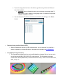
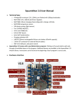
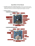
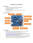
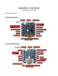
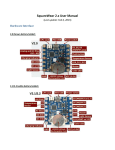
SquareWear 2.0 User Manual Technical Spec o ATmega328 running at 3.3V, 12MHz, pre-flashed with USBasp bootloader. o MCP1700 3.3V / 250mA LDO linear regulator. o MCP73831 lithium charging chip (configured to charge at 35mA). o MCP9700 temperature sensor. o 10K photo-resistor (light sensor). o Four 2N7002 MOSFETs. o 5mm color (RGB) LED. o 8.5mm SMT buzzer. o 6mm SMT tactile button. o Charging indicator LED. o LIR2032 (20mm) rechargeable lithium coin battery (45mAh capacity). o 2.0mm JST connector for external lithium battery. o SMT mini-USB port, and power switch. SquareWear 2.0 comes with a pre-flashed demo program. Clicking on the push-button will cycle through all available demos in the program. Additional demos are available in the SquareWear 2.0 Arduino library. Instructions can be found at the beginning of each program’s source code. Hardware Interface Power Options (IMPORTANT!!! Please READ!!!) o SquareWear 2.0 has a built-in rechargeable lithium coin battery (45mAH). Every time you plug in the mini-USB cable, it charges the battery automatically. SquareWear 2.0 uses rechargeable batteries only (either the built-in LIR2032 or external LiPo). Do NOT use it with non-rechargeable batteries such as CR2032. o You can power SquareWear by an external Lithium-Polymer (LiPo) battery (such as http://rayshobby.net/cart/accessories/acc-batteries/lipo-700). If using external LiPo, please remove the built-in coin battery!! To remove the built-in LIR2032, carefully push back the metal tap on the battery holder, until you can lift the battery up. DO NOT force lifting the battery as it may break the battery holder. If it ever breaks, use some hot glue to fix it back in place. o The build-in lithium charger (MCP73831) is set to charge at 40mA per hour (the charging current can be modified by changing a resistor). This will fully charge the coin battery in 1 hour. The charging time for external LiPo varies depending on the battery capacity. The green LED will turn off when battery is fully charged. o SquareWear has a built-in LDO (MCP1700) to provide regulated 3.3V from battery. When battery voltage drops below 2.7V, the microcontroller will stop running. In this case, you should plug in a USB cable and charge the battery for 15 minutes before using it again. o Keep battery plugged in at all times. Certain functionality, such as buzzer and USB bootloader, may not work reliably if the battery is removed. Pin Names and Functions o SquareWear 2.0 is based on ATmega328 – the same chip in standard Arduino. Therefore it uses the same pin names and functions as the standard Arduino. o Digital I/O pins: the board has 8 available digital I/O pins D0 / D1 (also serial RX / TX pin) D3 / D5 / D6 (MOSFET pins, support PWM) D10 / D11 (support PWM) D13 (internally wired to blue LED) *** PWM (Pulse Width Modulation), also referred to as analog output, provides adjustable level of voltage. You can use PWM to control the brightness of the LED, the speed of a motor etc. All PWM pins can function as standard digital I/O pins, but additionally you can use Arduino’s analogWrite function to set analog voltage levels. As described above, D13 is internally connected to the blue channel of the RGB LED. Setting this pin HIGH will light up the LED. *** MOSFET Pins D3, D5, D6 support PWM, and in addition they are internally wired through MOSFETs. The MOSFETs function as ‘Power Sinks’. This means setting the pins to logical high will connect them to GND, and setting them low will disconnect them from GND. Therefore, in order to use MOSFET pins, such as for controlling an LED, you need to connect the positive lead of the LED to VCC, and negative lead to one of these Power Sink pins. By setting the pin high or low, you can control the LED. The main advantage of Power Sink pins is that they can drive a high amount of current, so your LEDs will look very bright, your speaker will sound loud, etc. You can also use the MOSFET pins to drive a motor, a heat wire, a muscle wire etc. Each MOSFET can drive up to 250mA current. You can combine the three MOSFET pins together to drive more current. o Analog Input pins: SquareWear 2.0 has 4 available analog input pins A2 A3 A4 (also I2C SCL pin) A5 (also I2C SDA pin) Analog pins can be used to read an analog signal, such as sensors. They can also function as standard digital I/O pins. o Internally Assigns Pins (not available for general-purpose applications): D2: USB DD4: push-button (also used to enter bootloader) D7: USB D+ D8: red channel of the RGB LED D9: buzzer D12: green channel of the RGB LED D13: blue channel of the RGB LED A0: light sensor A1: temperature sensor o Sewing: SquareWear has large pin holes, allowing you to stitch conductive threads through them and attach the board to textile or fabric. You can also solder wires directly to the pin pads, or solder sew-on snaps to allow quick attachment to / detachment from textile. Programming SquareWear 2.0 Pre-Requisites: o The recommended way to set up software is by downloading one of the following preconfigured Arduino installation files: Mac: http://rayshobby.net/software/arduino-1.0.5-squarewear-macos.zip Win: http://rayshobby.net/software/arduino-1.0.5-squarewear-windows.zip Linux32: http://rayshobby.net/software/arduino-1.0.5-squarewear-linux32.zip Linux64: http://rayshobby.net/software/arduino-1.0.5-squarewear-linux64.zip o These installation files are based on Arduino 1.0.5 and have pre-installed necessary files to get you started. They also contain drivers for Windows, and SqureWear demos. o Mac OS users: if the pre-configured software package gives you an error Arduino.app is damaged and can’t be opened, this is because the latest OS X requires signed apps. The temporary work-around is to turn off this requirement in system settings. The solution is described in this page. o After installation, run Arduino 1.0.5 from the installed folder. Then in the menu, select Tools->Boards->SquareWear 2.0 o There are many provided example programs, which you can find in File->Examples>SquareWear2->… Enter Bootloader and Upload a Program: o To upload a program, plug in a mini-USB cable to the USB port. First turn off SquareWear (by sliding the power switch to Off position). Then press the pushbutton while turning on the power switch. At this point, the normal application will stop running, and the controller will present itself as a USBasp programmer to the host computer. In Windows, you need to install USBasp driver if you haven’t done so previously. The driver is included in the Arduino1.0.5/drivers/usbasp folder. In Linux, you need to create a file in /etc/udev/rules.d/ to give permission to the USB device. Alternatively, run Arduino in sudo mode. o Next, to upload a program, click on the Upload button in Arduino. Once the program is uploaded, the microcontroller will start running the program immediately. If the Arduino output reports the following error: avrdude: error: could not find USB device "USBasp" with vid=0x16c0 pid=0x5dc That means either you did not successfully enter program mode, or if you are in Linux, you don’t have system permission to use the USB device. If the output reports the following warning, it’s normal. Just ignore them: avrdude: warning: cannot set sck period. please check for usbasp firmware update. avrdude: error: usbasp_transmit: error sending control message: Broken pipe o To upload a new program, repeat the above steps. Using Existing Arduino Programs: o Because SquareWear 2.0 is based on Arduino, you can upload any existing Arduino program. The Arduino software has numerous example programs. Just make sure that you modify the program to match the pins assigned on SquareWear 2.0. Using the SoftPWM library: o The color LED is not wired to hardware PWM pins, so you cannot use analogWrite directly on the color LED. But the SquareWear library includes a SoftPWM (software PWM) library that can simulate PWM on these LEDs. o To use the library, you need to include both HIDSerial.h and SoftPWM.h in your sketch. In the setup() function, call SoftPWMBegin(); then use SoftPWMSet(pin, value)to set a PWM value (0 to 255) to a pin (any digital pin). o Check the fade demo for an example use of software PWM. Using the HIDSerial library: o SquareWear does not have built-in USB-serial converter. Instead, it simulates USB functions in software, using the V-USB library. The serial communication is implemented through the HID (human interface device) protocol, which requires no driver installation. o Check the hidserial demo for example. The library is designed to be compatible with Arduino’s Serial class as much as possible. o To use the library, you need to include HIDSerial.h in your sketch. o Specify a global HIDSerial class variable. For example: HIDSerial serial; o In the setup() function, call serial.begin(); o Use serial.write(char) to write a single character. Use serial.print or println to write a string. o Use serial.available() to check if there is an incoming string (from host computer). o Then use serial.read to read the incoming string. o Important: because the library is not interrupt driven, you must call serial.poll()as frequently as possible to handle USB requests in time. This can be done by inserting serial.poll() in the inner loop and ensure that it’s called frequently. o Host software: to use the HID serial function, you need to run host software called HID Serial Monitor. It’s cross-platform. To use the software: First click on the Connect button to connect the device (if unsuccessful, check if SquareWear is turned on and if you have followed the above descriptions for calling serial.begin() and serial.poll() in your sketch. Once connected, whenever a string is transferred from the device to host, it will be displayed in the text area. To send a string from the host to the device, type the string in the text field, and then click on Send. Limitation: due to software limitation, do not send a string longer than 32 characters at a time. Sending a string longer than 32 characters may results in buffer overflow or an error. You can also pause the device and host communication by clicking on the Pause button. Simulate Human Interface Devices (HID): o Because SquareWear uses the V-USB implementation, you can program it to simulate a mouse, a keyboard, or other HID devices. Examples can be found in the V-USB website. Using Adafruit’s Neopixel Library: o The SquareWear software pack has pre-installed Adafruit’s Neopixel library. You can use it to interface with WS2811/2812/2813 LED strips/matrices. The SquareWear examples include a few demos (ledpad-xxx). These assume the LED strip / matrix is connected to VCC, GND, and pin D1.