1
30
Construction
Kit
SPECTRUM, C64 & AMSTRAD CPC
CONTENTS
INTRODUCTION
REGISTRATION AND ACKNOWLEDGEMENTS
LOADING INSTRUCTIONS
INTRODUCTION TO FREESCAPE
INTRODUCTION TO THE EDITOR
THE USER INTERFACE
MOVEMENT AND VIEWPOINT CONTROLS
THE 3D KIT GAME
CREATING AND EDITING YOUR FIRST OBJECT
FILE MENU OPTIONS
GENERAL MENU OPTIONS
AREA MENU OPTIONS
CONDITION MENU OPTIONS
THE SHORTCUT ICONS
CONDITIONS - FREESCAPE COMMAND LANGUAGE (FCL)
EXAMPLES
VARIABLES - HOW TO USE VARIABLES
HANDLING VALUES GREATER THAN 255
APPENDIX
2
2
3
6
11
13
15
16
16
17
18
21
23
24
28
41
42
43
45
INTRODUCTION
Welcome to the 3D Construction Kit. We had often been asked when a Freescape
creator would be made, so here it is ! It represents a total of four and a half years of
actual development, and many more man -years.
The program uses an advanced version of the Freescape 3D System , and will
allow you to design and create your own 3D Virtual Worlds. These could be your living
room, your office, an ideal home or even a space station!
You may then walk or fly through the three dimensional env ironment as if you
were actually there . Look around , up and down, move forward and back, go inside
buildings and even interact with objects you find . The facilities to make a fully fledged
action adventure game are even included : just add imagination ...
Most of all , though, just have fun creating , experimenting , colouring and playing in
3D - You can easily lose all track of time.
I hope you enjoy using the 30 Construction Kit as much as we enjoyed creating it.
Have fun !
Ian Andrew
REGISTRATION
It is essential to register as a 30 Construction Kit user, as support can only be
given to registered owners. The registration form is included with the package.
All correspondence should be sent to Mandy Rodrigues , at the address shown
below. If a reply is required a stamped addressed envelope must be enclosed .
THE 3D CONSTRUCTION KIT USER'S CLUB
The Club is provided to offer additional help and advice for users of the 3D
Construction Kit and will consist of a bi-monthly newsletter packed full of news,
information, hints and tips on the system to allow everyone to use it to it's full potential.
It will also act as a forum for users to exchange ideas and information. To apply for
membership to the club, just fill in the relevant section of the registration card and
further details and information will be sent to you. All registration forms should be sent to :
Mandy Rodrigues , 67 Lloyd Street,
Llandudno, Gwynedd , LL30 2YP.
ACKNOWLEDGEMENTS
Produced and conceived by :
Design team :
Programmed by: SPECTRUM/
AMSTRAD/C64
Kit game & Graphic Design :
Additional programming :
Freescape development:
Ian Andrew
Ian Andrew
Paul Gregory
Eugene Messina
Kevin Parker
Kevin Parker
Messina
Sean Ellis
Chris Andrew
2
Manual by :
Typesetting :
Additional contributions :
Mandy Rodrigues
Peter Carter of Starlight Graphics
Andy Tait
Helen Andrew
Anita Bradley
Ursula Taylor
Thanks also to :
Domark Software
[jII 8:4'1~.U g'" is a registered trademark of Incentive Software .
Program and documentation copyright © 1991 New Dimension International
Limited, Zephyr One , Calleva Park, Aldermaston , Berkshire RG7 4QW.
NOTICE
It is a criminal offence to sell , hire, offer or expose for sale, or hire or otherwise
distribute infringing (illegal) copies of this computer program or its documentation
and persons found doing so are liable to criminal prosecution . Any information on piracy
should be passed to The Federation Against Software Theft (FAS1), 2 Lake End Court,
Taplow, Maidenhead, Berkshire SL6 OJQ .
DISCLAIMER
Du.e to. the complexity of th.is program, Incentive Software ("The Company")
hereb¥ d1scla1ms all warranties relating to this software, whether express or implied,
1nclud1ng without limitation any implied warranties of merchantability or fitness for a
particular purpose . The Company will not be liable for any special , incidental,
~onsequential, indirect or similar damages due to loss of data or any other reason , even
1f The Company or an agent of The Company has been advised of the possibility of
such damages. In no event shall The Company's liability for any damages ever exceed
the price paid for the licence to use software , regardless of the form of the claim. The
person using the software bears all risk as to the quality and performance of the
software .
LOADING INSTRUCTIONS
AMSTRAD CPC
Cassette - 64K CPC models (CPC 464, CPC 464, CPC 664 with
cassette recorder).
Loading The Environment Editor
Insert Cassette 1 with Side 1 facing upwards and rewind .
On machines with Disc Drives attached, type 'Jtape ' followed by <return> (the
character is obtained by pressing the Shift key and '@' together.)
Type 'RUN·' followed by <return> and follow on -screen instructions.
'I'
Loading The Condition Editor
Insert Cassette 1 with Side 2 facing upwards and rewind .
On machines with Disc Drives attached, type ' Jtape ' followed by <return> (the
character is obtained by pressing the Shift key and '@' together.)
Type 'RUN•' followed by <return> and follow on-screen instructions.
'J'
3
Loading The Freescape Compiler
Insert Cassette 2 with Side 2 facing upwards and rewind . On machines with Disc
Drives attached, type '!tape · followed by <return> (the 'I' character is obtained by
pressing the Shift key and '@ ' together.) Type 'RUN 'compiler' ' (no spaces) followed by
<return> and follow on -screen instructions.
Please note: it will take a while before the compiler starts loading since various
data files are located at the beginning of this side .
Cassette - 128K CPC Models
Loading The 128K 3D Construction Kit
Insert Cassette 2 with Side 1 facing upwards and rewind . On machines with Disc
Drives attached, type 'ltape ' followed by <return> (the 'I' character is obtained by
pressing the Shift key and '@' together.) Type 'RUN ' ' followed by <return> and follow
on-screen instructions.
Loading The Freescape Compiler
Follow instructions for loading the compiler on 64k models.
Amstrad Disc
Insert disc with Side 1 facing upwards. Type 'run"disc' followed by <return> key
and follow the on-screen instructions.
Data Files:
To save your 3D worlds onto disc, you will need to format a blank data disc using
the supplied formatting utility.
N.B. DON'T FORMAT YOUR CONSTRUCTION KIT DISC.
Format a disc in the normal manner if you wish to save a stand-alone data set from
the compiler.
Example data files - 'The 3dkit game ' and border graphics are located on s_ide 2 of
the disc. Ensure this side is inserted upwards when loading the sample data into the
Construction Kit.
SPECTRUM
Cassette - 48K models
Please note : it will take a while before the compiler starts loading since various
data files are located at the beginning of this side .
Cassette - 128K Models
Loading The 128K 3D Construction Kit
Insert Cassette 2 with Side 1 facing upwards and rewind . Use loader option (refer
to Spectrum manual) and press PLAY on the cassette player.
Loading The Freescape Compiler
Follow instructions for loading the compiler on Spectrum 48K models.
SPECTRUM +3 Disc
Insert disc with Side 1facing upwards and use loader option (refer to Spectrum
manual) . Follow on-screen instructions.
Data Files:
To save your 3D worlds onto disc, you will need to format a blank data disc using
the supplied formatting utility.
N.B. DON 'T FORMAT YOUR CONSTRUCTION KIT DISC.
Format a disc in the normal manner if you wish to save a stand-alone data set from
the compiler.
Example data files - 'The 3dkit game' and border graphics are located on Side 2
of the disc. Ensure this side is inserted upwards when loading the sample data into the
Construction Kit.
NOTE:
Upon loading an editor, a screen will appear which asks for one of the following
options to be selected:
1. Sinclair Joystick.
2. Cursor keys (0 = fire) .
3. Kempson Joystick.
The cursor keys option emulates a joystick and pressing the 0 key emulates the
joystick fire button.
COMMODORE 64
Loading The Environment Editor
Insert Cassette 1 with Side 1 facing upwards and rewind. Type load"" (no spaces)
followed by <return> and press PLAY on the cassette player.
Loading The Condition Editor
Insert Cassette 1 with Side 2 facing upwards and rewind .
Type load"' (no spaces) followed by <return> and press PLAY on the cassette
player.
Loading The Freescape Compiler
Insert Cassette 2 with Side 2 facing upwards and rewind. Type load'" (no spaces)
followed by <return> and press PLAY on the cassette player.
4
Commodore 128 users must enter C64 mode before loading (refer to manual)
Cassette
Loading The Environment Editor
Insert Cassette 1 with Side 1 facing upwards and rewind. Press SHIFT and
RUN -STOP together and press PLAY on the cassette player.
Loading The Condition Editor
Insert Cassette 1 with Side 2 facing upwards and rewind . Press SHIFT and
RUN-STOP together and press PLAY on the cassette player.
Loading The Freescape Compiler
Insert Cassette 2 with Side 2 facing upwards and rewind. Press SHIFT and
5
RUN -STOP together and press PLAY on the cassette player.
Commodore Disc
Insert disc with the label facing upwards and Type LOAD": *" ,8, 1 followed by
<return> key (refer to commodore manual) . Follow on-screen instructions.
Data Files:
Ensure you have some blank , formated disks at hand with which to save data.
DO NOT FORMAT, OR SAVE ONTO, YOUR PROGRAM DISK !
INTRODUCTION TO FREESCAPE
The 3D CONSTRUCTION KIT uses an enhanced version of the FREESCAPE®
system. The system allows you to represent a virtual world that you can move around
and interact with . Th is world is represented in three dimensions, known as X, Y and Z.
X is equivalent to left and right.
Y is equivalent to up and down .
Z is equ ivalent to near and far.
Movement around the world is achieved by using the icons in the editor (refer to
later sections) , or by using the keys listed in the append ix. Pressing the CONTROL key
on Amstrad or Commodore, or SYMBOL SHIFT on Spectrum , whilst moving or turning
speeds up the action .
AREAS
The world is divided into regions known as "AREAS ". Each area is like a box and
has a set size of 8192 (X) • 4096 (Y) • 8192 (Z) units. These units are an arbitrary form
of measurement which could easily be thought of as being millimetres, centimetres or
metres. One unit is the smallest distance that you can move through .
X YZ
A co-ordinate of X=O Y=O Z=O (View: 0000,0000,0000) represents the nearest
bottom , left hand corner of an area .
The world is seen from a single viewpoint which occupies one unit, looking in
different directions. The direction is represented by three angles:
X rotation represents looking up or down (pitch)
Y rotation represents looking left or right (yaw)
Z rotation represents looking sideways (tilting your head) (roll)
These rotations are measured in degrees and 360 degrees means that you have
turned full circle. Rotations are limited to multiples of 5 degree steps.
Rotations of X=O Y=O Z=O (ROT: 000 ,000 ,000) means that you are looking
straight ahead . Changing the Y rotation by 180 (ROT: 000 ,180,000) by doing a U-turn ,
means that you are looking directly behind you .
Changing the X rotation to 90 (ROT: 090,000,000) means that you are looking
straight down. An X rotation of 270 (ROT: 270 ,000 ,000) means that you are looking
straight up.
There can be up to 254 different AREAS defined by the user. An AREA can be
used to represent a room of a house or an "outdoor" region. You can not travel beyond
the boundary of an area.
AREAS have no geographical relation to each other, but are tied together by
6
ENTRANCES. An ENTRANCE has a position and view direction . The user can then be
placed at an E~TRANCE position in a specific AREA by some form of trigger (ie. walking
into a door. This could effectively "move " the viewer from a hall (one AREA) into a room
(another AREA) .
OBJECTS
Objects can be placed into an area to make the environment. These are solid
~nd , as such, cannot be passed through when moving. Objects can have different sizes
in X, Y and Z directions. Object position and size are measured in a different
co-ordinate system to the 3D world .
. On_
e unit _in Object ~a - ordinates is equal to 64 units in the 3D world system . ie. an
Object with a size of 1 unit takes up 64 units in the 3D world . Objects must be placed at
64 world un it boundaries , ie. it is not possible to place an object at co -ordinate 32 in
world units.
_There are several basic object types ("PRIMITIVES") which can be re -sized and
combined to make larger, more complicated objects such as buildings, trees etc.
The primitive objects consist of :
CUBOIDS
3 Dimensional boxes where the sides can be stretched and shrunk in 3 directions
(X , Y and Z) .
PYRAMIDS
FREESCAPE pyramids are similar to conventional pyramids but are truncated at
the top. (They are initially flat on the top) . A FREESCAPE pyramid , like the cube can be
stretc~ed and shrunk in 3 directions, but can have its sides pushed in to tor~ a true
pyramid or pushed out to form a cuboid . The pyram id can be rotated so that its base is
on any of its six sides.
RECTANGLES
Flat (2 dimensional) boxes whose sides can be stretched and shrunk in three
directions at any time .
LINES
Two points in 3D space joined together form a line. These two points may be
moved in three directions .
TRIANGLES
.
_Three points in 3D space form a triangle . These points may be moved in three
directions.
QUADRILATERALS
. Four points in 3D space form a quadrilateral. This can be non rectangular. These
points may be moved in three directions.
PENTAGONS
As triangles but with five points .
HEXAGONS
As triangles but with six points.
7
SENSORS
Single 3D point which can be moved in three directions. Se.nsors have the ability
to detect your presence within a defined distance and even to fire at you! These are
described in greater detail later on .
Objects such as pyramids and triangles, which do not occupy a whole .cu.be of
space, act like solid cubes when moving around the 3D wo~ld . For example, 1t is n?t
possible to stand on the slope of a pyramid . This cube 1s known as the objects
BOUNDING CUBE .
When editing points within these object, the points are stored as a fraction of the
total object size. This fraction is represented as a number between 0 and 6~ • .where 0
means that the point is at one side (minimum) of the cu~e and 63 means 1t ~s at. the
opposite side (maximum) . Each point has a different scale 1n each of the three d1rect1ons
(X,Y and Z) to show its position with the objects BOUNDING CUBE.
For example : to make a pyramid with the apex (the pointed top) in the middle of
the face of the BOUNDING CUBE, the apex would have X and Z values of 32 and a Y
value of 63.
OBJECT ATTRIBUTES
Objects can exist in three states : VISIBLE , INVISIBLE or DESTROYED .
VISIBLE:
The object is present in the world as a solid form.
INVISIBLE:
The object is not present in the world but can be brought into the world by being
made visible.
DESTROYED:
Once an object is destroyed it is invisible and cannot be made visible again (until
the world is reset) .
OBJECT COLOURS (SHADES)
Each side of an object can have a different shade. A shade is made up of a mixture
of the colours available on the comput ~ r used .
The first shade (number O) has a special property in that it is not draw~. This ~an
be used to improve the speed of drawing the 3D world when used on object. s1d.es which
are never seen, such as the under side of a house or the back of a door which 1s placed
against a wall.
By painting all of the sides of an object with shade 0 it is possible to have an. object
which cannot be seen but which is solid and cannot be moved through. Note: In this case
the object's attribute will be set to VISIBLE even though it cannot be seen . This can be
used to produce invisible barriers or invisible triggers on floors.
However, an object that is used globally will only appear at the same co-ordinate
position as it was defined in. So a tree defined in the corner of the GLOBALS AREA
can only appear in the same corner of the AREAS it appears in.
INTERACTION WITH OBJECTS
Events or reactions can be caused by interacting with objects within the environment. Objects may be triggered to respond to being shot, activated (touched/pressed/
manipulated), collided with or walked on .
In order to shoot or activate an object. a "sight" mode is selected (by pressing the
SPACE BAR) whereupon a cross-hair appears and is controlled using the normal
movement keys or joystick. After targetting an object, the fire button or 0 key, when
pressed, will then shoot at that object. To activate a targetted object the "A" key is
pressed . However, an object will only be "activated " if the object is within a predefined
distance known as the ACTIVE RANGE .
SENSORS
A SENSOR is a special type of object that will detect your presence if you are
within a set distance from it. This allows reactions to occur when approaching an
object. A Sensor can also be set to respond by firing back at you at a given rate .
CONDITIONS - THE FREESCAPE COMMAND LANGUAGE (FCL)
In order to interact with objects, checks and actions have to be defined in the
form of short programs called CONDITIONS.
CONDITIONS are written using instructions which make up the FREESCAPE
COMMAND LANGUAGE (FCL) . FCL has a very simple but powerful set of commands
which allow you to manipulate and respond to any occurances.
There is also a bank of memory which can be used by the user to store and view
information relating to the environment and events. Each memory cell is called a
VARIABLE. A VARIABLE can store a value between 0 and 255 . There are 128 of these
memory cells and are numbered 0 - 127. The first 112 (0-111) are free for the user to
use for storage, whilst the last 16 (112-127) are defined and used by the system but can
be viewed by the user and acted upon, if desired.
There are various categories of instructions in FCL and they are as follows:
VARIABLE MANIPULATION
This set of instructions act upon values stored in the VARIABLE memory cells.
These include commands to add to and subtract values from VARIABLES, comparisons
of values and setting a value .
OBJECT MANIPULATION
This set of instructions can alter the attributes of a specified object. There are
instructions to visiblise, invisiblise, destroy and swap the visibility of objects.
GLOBALS
In order to conse~e memory, common objects may be stored in a reserved area
known as the GLOBALS AREA (AREA 255). These objects can be placed in any area by
using the GLOBAL option in the editor. For example :
A floor that would be duplicated in other areas could be defined once as an object
in the GLOBALS AREA and displayed in each area that would have the same floor.
VEHICLE COMMANDS
This set of instructions affect the type of movement you have within the environment. They allow you to set movement to crawling, walking, running and flying. A
command is also available to move the user to a specified ENTRANCE in a specified
AREA .
CONDITIONAL INSTRUCTIONS
This set of instructions allow the execution of segments of programs depending
8
9
on the outcome of specific checks , such as: If a particular object is shot. If a particular
object is collided with, if a SENSOR has sensed you etc.
MISCELLANEOUS COMMANDS
This set of instructions deal with functions such as printing text messages, setting
colours, playing sounds and setting the TIMER. The TIMER is a device that can be set
to trigger a set of conditions at a defined regular interval of time.
CONDITION ROUTINES (the short programs written in FCL), are stored as lists.
Each list is given a number for identification. There are three types of groups of
conditional lists. They are :
•
GENERAL CONDITIONS
LOCAL CONDITIONS
PROCEDURES
message can be printed to the screen by referring to its message number and its
position at which it should be placed . This allows frequently used messages to be
stored once .
LIMITATIONS TO FREESCAPE •
As FREESCAPE uses extremely complex mathematical algorithms to represent
the 3D world on a 2D screen, there are a few basic limitations to what you can do:
Objects should not overlap. The bounding cube of one object should not occupy
the same 3D space as any other. This is especially true when you have GLOBAL
OBJECTS or objects which are made visible which overlap with normal objects.
The number of visible objects in any one AREA is limited due to memory
restrictions. Excess objects are not drawn. The maximum number of objects depends
on the computer you are using.
GENERAL CONDITIONS
These are a set of conditional lists (programs) which are executed all the time .
Conditions used in this form are useful for checking for "End Game" situations,
maintaining counters, and general overseeing of the whole environment. The first
CONDITION in this set is only executed when the environment is reset. This allows you
to initialise any variables or events at the start.
THE 3D KIT PROGRAMS
On 48K/64K machines such as the Spectrum 48K, CPC464, CPC664, CPC464+
or Commodore 64, the Kit is split up into three programs :
LOCAL CONDITIONS
These are a set of conditional lists which are also executed all the time . However,
there is a set of local conditions for each AREA. Only the set of conditions associated
with the current area will be executed . LOCAL CONDITIONS are useful for checking
and acting upon collisions with objects in the current AREA, Sensor handling , or any
other occurances that are AREA specific.
THE CONDITION EDITOR
This allows you to edit the Conditions.Instruments, Messages and to test the world
without the Editor screen.
PROCEDURES
These are a special set of conditional lists that are only executed at the request of
another condition . Their main use is to replace frequently used functions by conditions,
only being written once, thus preserving memory. They can also be used to extend the
length of a condition list if a cond ition exceeds the maximum number of lines allowed .
INSTRUMENTS
An Instrument is a device which displays information to the user. Instruments are
not visible whilst in the editor, but are visible on the TEST screen or in a Stand -alone
environment. There are two types of Instrument: BARS and NUMERICAL.
BAR Instruments are used to display the value held in a variable as a bar of a
length in pixels (dots) equal to that value . They are always one character wide and can
either be horizontal or vertical.
NUMERICAL Instruments are used to display the value held in a variable as a
decimal figure . They can be set to display to a length of 1 to 5 characters . To display
four or five characters, two variables are used to hold the value (see section on "HOW
TO USE VARIABLES" and "MORE ABOUT VARIABLES' in the manual) .
MESSAGES
Messages are a way of communicating to the user by way of printing text to the
screen. They are only visible on the TEST screen or in a 'Stand-alone' environment Messages are stored in a list; each item in that list being a single line of text. Each
10
THE ENVIRONMENT EDITOR
This allows you to edit Objects, Areas, Entrances and Colours .
THE FREESCAPE COMPILER
This allows you to combine your 3D world together with your own border to create
a Stand-alone program which can run without the Kit.
DATA can be loaded and saved to and from each program to create the complete
world .
On 128K machines such as Spectrum 128K, +2, +2A, +3, CPC6128 or CPC6128+
(excluding Commodore 128), the Environment Editor and the Condition Editor are
combined and more memory is available to create larger worlds .
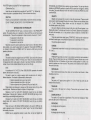
INTRODUCTION TO THE EDITOR
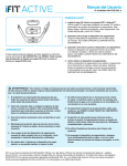
The Main Screen (see figure 1) is divided into five main areas:
1. The MENU BAR showing a list of Menu headings and the amount of memory
remaining.
2. The VIEW WINDOW which normally shows a 3D view of your world.
3. The STATUS LINE which sows you some useful information such as your
position in the 3D world.
4. The FREESCAPE ICONS which allow you to move around the world.
5. FURTHER ICONS (these change depending on what you are doing).
The 3D Construction Kit is designed to be user-friendly with icons and pull-down
menus enabling the user to quickly understand the working environment.
Editor functions can be selected in one of two main ways :
1. ICONS are small boxes with either images or text in them showing what the
icon is used for.
11
2. MENUS contain lists of functions which can be selected .
Upon loading the program you will see the Main Screen (Figu re 1).
A box-shaped cursor will appear over one of the icons in the centre of the screen .
!his _cursor highlights the currently selected icon. Pressing up, down, left or right on the
JOyst1c~ alloy.'S you to move t_
he cursor around the screen from icon to icon. Pressing fire
on the Joystick activates the icon . For example: If the cursor is over the MODE icon then
the mode will change . Moving the cursor above the top row of icons activates the
MENU BAR .
THE MENU BAR consists of a series of headings at the top of the screen such as
FILE . One heading is ~ighl i ghted at any time . Pressing left or right on the joystick
moves to the other headings. Pressing down on the joystick moves the cursor back onto
the icon.s. Pre~sing I.ire over a heading will make a list of options (known as a menu)
appear 1n the View window and the highlight will move to the first of these options. For
example :
In. the FIL~ menu .there are options for LOAD and SAVE (there may be others
depending on which version of the Kit you are using).
By moving the joystick up or down you may move the highlight to the option that
you y.'ant or Y.ou ~ay leave that menu by moving the highlight above the first option in
the list. Pressing fire will select the option .
MENU SELECTOR
VIEW WINDOW
INFO BAR
}
SHORT CUT ICONS
MAIN SCREEN
Figure 1
FREESCAPE ICONS
Below the Menu Selector you will see the main VIEW window. Th is area is always
used to display the current FREESCAPE view.
Below the VIEW window is the INFORMATION BAR. This initially reads AREA001
VIEW 4064 ,0544,4064 000,000 ,000 (This may vary depend ing on the type of computer
used) . This shows the current area , your present viewpoint co-ordinates (shown as
X,Y,Z) , and the angle of view (yaw. pitch and roll) . When in edit mode this line will change
to read the object name you are editing , its position in the environment and its size .
Below the Information Bar you will see a series of icons. These are the MODE
and FREESCAPE icons. The MODE icons are on the left of the screen. The VIEW icon
is very useful. Whenever selected , the editor's VIEWpoint of the environment will cycle
through North , South, East, West and Top View. Alongside this you will see an icon
called MODE. Mode cycles between WALK, FLY1 and FLY 2.
THE USER INTERFACE
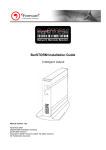
DIALOGUE BOXES
There are various parts of the environment creation which will require input from
you to set the parameters relating to the current function . These parameters will usually
be set within a DIALOGUE BOX. (See figure 2) .
The setting of parameters is achieved either by selection or by typing values (with
the exception of entering/editing MESSAGES, which allow for alphanumeric characters) .
DIALOGUE BOX
Figure 2
To enter or edit a numerical parameter. you must highlight the value then select it.
The value will be cleared and a cursor appears, allowing you to enter a numeric value .
To end editing of a particular text item, simply press the RETURN or ENTER key
whereupon the cursor will be removed and any restrictions on numerical values will be
applied i.e. if you were to type in the number 900 for the activate range and as the
maximum value is 255 , it will automatically be restricted to 255 on pressing RETURN .
Note that while editing a parameter it is impossible to exit the DIALOGUE BOX or edit
any other items until you have finished editing the current parameter by pressing
RETURN or ENTER .
MODE ICONS
12
13
EDITING FCL CONDITIONS - THE LINE EDITOR
The Condition editing screen will appear after selecting a condition from a list for
editing. Upon entering the the condition editor, if the condition is empty, you will see a
blank screen with a bar, of half the screen width, at the top. The word END is written on
the left hand side . This word is in fact an FCL (Freescape Command Language)
instruction. This instruction will always appear at the end of the command list (But you
place more END instructions anywhere in a list to end the processing of a command list
prematurely) .
The bar serves to highlight the line selected for editing, or the line at which new
instruction lines will be inserted .
Pressing a letter key starts the command entry. A cursor appears at the bottom of
the screen , allowing you to ed it what is being typed . The editor will only allow you to
type up to eight characters before the cursor jumps ahead to new position in the line.
This is because Freescape instructions are no longer than eight characters in length.
The position that the cursor jumps to signifies the start of a parameter field . Pressing
SPACE will also take you to the next field if the command has less than 8 characters.
An FCL instruction can have from zero to three parameter fields (depending on the
instruction) . Each parameter field consists of a number between 0 and 255 . Pressing
the space bar moves the cursor to the next field . Only Alphabetic characters may be
typed in the first field (instruction field), and only Numeric characters in the three fields
following (parameter fields) .
Pressing Return (Enter) will place the line into the instruction list at the line
highlighted by the bar. However, if there is an error in the typing or format of the line,
then it will not be placed in the instruction . The screen will flash red and the cursor will
appear in the field where the error occured .
To correct errors, use the left and right cursor keys to move the cursor along the
line . The delete (shift+O Spectrum 48K) key will move the cursor left one character
deleting the character it moved onto. It is also possible to type over characters that
already exist on the line.
When not editing a line :
The up and down cursor keys will move the highlight bar through the instruction
list (if there is more than one line).
Pressing shift+D will delete the line highlighted by the bar (it will not delete the
last END instruction) .
Pressing shift+E will allow you to edit the line highlighted by the bar (it will not
edit the last END instruction).
Pressing shift+C will clear the whole condition list.
Pressing ESC(CPC), RUN-STOP(C64), BREAK/shift+SPACE (Spectrum) or
shift+X (on all formats) will leave the condition editor.
(Spectrum users note: all references to Shift means the use of the Caps Shift key)
Note: If the instruction list reaches the bottom of the screen it continues in
another column on the right hand side of the screen . The maximum number of lines that
can be edited is two columns worth.
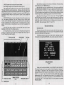
MODE & FREESCAPE ICONS PANEL
Figure 3
look in a different direction. Select the eye level icon to look forwards if you get
confused .
The U-turn icon is used to turn around 180 degrees so that you can look directly
behind you . The cross hair icon turns the movement cross in the centre of the view
window on or off.
Selecting the MODE icon changes your current mode of movement. The possible
modes are:
WALK : This mode allows you to walk around various objects and to climb them if
they are not too high. However, you are limited by gravity so that you cannot leave the
ground. Pressing down and up in Walk mode allows you to crouch down or stand up
again. When crouched you may be able to move under an object which you would not fit
through when standing . However, when crouched you cannot move forwards as fast so
it is a good idea to be standing most of the time .
FLY 1 and FLY 2: These two modes are very similar. They allow you to fly through
the 3D world as if you are wearing a jet pack!! The difference between Fly 1 and Fly 2 is
that when moving forwards in Fly 1 you move parallel to the ground (at a constant
height) whereas in Fly 2, if you are looking down and you move forwards your height
will decrease. Fly 2 flies in the direction you are looking .
The VIEW icon is useful for looking at the whole of the current area . Normally this
icon shows arrows pointing to the Mode icon which means that the View mode is not
operational. Selecting the View icon cycles between NORTH, SOUTH, EAST, WEST or
PLAN which shows you the whole area from that direction. (PLAN shows you the area
from directly above) .
If you find using the FREESCAPE movement icons confusing, then you can also
use the keys listed in the back of this manual to do most of the useful things.
Note that the EDIT and FREESCAPE icons remain on the screen and can be
used at most times during editing .
After loading you will be able to see some more icons below the movement icons.
These allow you to change your 3D world . These icons are marked GLOBAL, COPY,
CREATE, EDIT, LOAD, RESET, SHADE, DELETE, ATTRIBUTES and SAVE. A
description of what each of these icons consist of will be found later in the manual (see
section on SHORTCUT ICONS) .
GETTING TO KNOW THE MOVEMENT AND VIEWPOINT CONTROLS
The movement icons in the centre of the screen can be used to move up, down,
forwards, backwards, left or right. The turn icons allow you to turn or tilt your head to
In order to demonstrate some of the features of the 3D Kit an example Data File
(3dkitgame) is included.
First load in the data file from the disc or cassette . Move the pointer to the LOAD
icon and press fire . A dialogue box will appear asking for the file number.
DISC USERS : The Kitgame is stored as File 9 on Side 2 of the disc. So insert the
14
15
MOVING AROUND THE 3D WORLD
disc with Side 2 facing upwards and press 9.
CASSETTE USERS: Put in the Cassette marked "Data Files" and rewind to the
beg inning . Press <return> when the Dialogue Box asks for the file number, and the
program will load the next file on the tape .
Now using the FREESCAPE icons experiment with moving around the new
environment. Move in all the directions you can until you become completely familiar
with how to move yourself around within the FREESCAPE landscape.
Pressing the SPACE BAR will bring up a cross-hair cursor within the view window
(this can be redefined) . This is your "sight" and can be moved around using the joystick
or cursor keys (depending on which option is selected upon loading with the Spectrum
version) . When in this mode, pressing the Fire button on the joystick (or the B key) will
"shoot", and the lines of the laser gun will appear on the screen, culminating at the
cross-hair cursor. In this mode , pressing the "A" key will in turn ACTIVATE an object
where the cross-hair cursor is positioned if the object is near enough . Note that
activate will have no visible effect unless conditions are entered for this function to
operate . Pressing the SPACE BAR once again will return control of movement.
THE 3D KIT GAME
This has been included as an example to illustrate some of the environments that
are possible . This is supplied as a data file and can be played as a stand alone game
by using the Freescape Compiler or within the condition editor. First, load the condition
editor (128K users can load the 128K Construction Kit) . Then , ensure that you insert the
kitgame tape/disc into the player/drive. From within the kit select LOAD from the FILE
MENU and load file number 9.
Select TEST from the GENERAL menu to play the game from within the Kit.
The object of the game is to escape from the mysterious world in which you find
yourself, and return to Earth . Some sort of space vehicle will probably come in handy
(large clue) . Pressing ESC, BREAK or RUN /STOP (depending on which computer you
are using) will return you to the Editor.
Advanced use has been made of conditions, and these can be examined and
edited using the relevant functions.
See if you can complete the game without cheating!
Next select the SHADE icon and you will see that a list of objects appears on the
upper left of the screen . At present it should show :
EXIT
001 ENTRANCE
002 CUBE
Select the CUBE . The screen should now change to show the SHADE PANEL.
To the left of the SHADE PANEL you still see six numbered rectangles which
represent the six sides of the cube , showing their current shades . To colour the cube,
select the side you wish to shade with the cursor, by highl ighting the values to the right
of the shaded rectang les numbered one to six. These values correspond to the value of
the shade shown as 16 shaded bo xes numbered 0 to 15, on the right hand side of the
panel.
Select a face and type in a number then press RETURN (or ENTER) to alter its
shade to shade . Repeat th is process until all si x of the rectang les are coloured to your
choice . You will also note that at the same time the cube in the VIEW window is also
being coloured . Entering O will make a side invisible .
Now we will edit the cube . Move the pointer to the OK icon and press the fire
button . The SHORTCUT icons will now reappear. Move the pointer to the EDIT icon and
press the fire button to select it. Now se lect CUBE 2 from the object selector list.
The EDIT window shows five different groups of icons, POINT, TURN , SHRINK ,
STRETCH and MOVE. The POINT icons will not function on cubes and rectangles .
Move the pointer to the STRETCH icons and press the fire button when over the
icon represented by an arrow pointing to the right. The cube will now stretch towards
the right. SHRINK has the opposite effect to STRETCH .
Experiment a little with these icons until you are completely fam iliar with
stretching , shrinking and turning/fl ipping the cube . Then try to bring the cube back to its
original size (8,8,8) .
When you have done this, move the mouse pointer to the OKAY icon and the
SHORTCUT icons will reappear. Now move the pointer to the COPY icon . The item
selector will appear in the usual way. Se lect the cube once again .
You will now see that the cube has been copied in the VIEW window. Th is will be
called CUBE 003 . The new cube can be edited in the same way by selecting the cube
from the item selector in the usual way.
FILE MENU OPTIONS
CREATING AND EDITING YOUR FIRST OBJECT
First the existing data file must be cleared from the VIEW window. If you are using
a 128K version of the 3D Kit move the pointer up to the MENU SELECTOR and move
along to the FILE menu. Move the pointer down until NEW is highlighted and press the
fire button . An ALERT BOX will appear warning that all current data will be lost if the
operation continues. Select OK and after a few moments the VIEW window will clear
revealing an empty area . Non 128K users will have to reload the Editor.
Now move the pointer to the SHORTCUT icons and select CREATE . These icons
will now be replaced with a further set of icons each showing a particular type of object
for you to select. Move the pointer to the CUBE icon and select it. A cube will now
appear in the VIEW window. Note that the SHORTCUT icons reappear once the cube
has been created.
16
Name:
SAVE
Function :
To save all the data in memory to disc or cassette as a datafile. On some
versions of the kit, A dialogue box appears . Select Tape , Disc or Abort. If
Tape is chosen then follow instructions for tape users. If Disc is chosen
then follow instructions for disc users.
TAPE USERS
Action :
A message appears asking you to Enter a File Number (0-9) . Pressing a
numbered key will cause the machine to save the DATA FILE . Ensure the
tape player is recording before pressi ng a numbered key.
Response: The current datafile will be saved to cassette .
17
DISC USERS
Insert into the disc drive, a formatted Kit data disc (formatted using the
Action:
supplied format utility) . A message appears asking you to Enter a File
Number (0-9) . Select a File number.
Response : The current data file will be saved to disc.
On Amstrad and Spectrum the Kit uses its own file system to save data,
Note:
and as such , the files will not appear to be present if the disc is catalogued .
REMEMBER to use discs formatted with the supplied format utility.
Name :
LOAD
To load data file from disc or cassette . On some versions of the Kit, a
dialogue box appears. Select Tape , Disc or Abort. If Tape is chosen then
follow instructions for tape users. If Disc is chosen then follow instructions
for disc users.
TAPE USERS
Action:
A message appears asking you to Enter a File Number (0-9) . Press the
relevant key to select the file number you wish to load or press the
RETURN (ENTER) key to load the next data file on tape .
Response: The data file will be loaded.
DISC USERS
Action:
A message appears asking you to Enter a File Number (0-9) . Ensure the
relevant KITDATA disc is inserted in the disc drive. Press the relevant key
to select the file number you wish to load .
Response : The data file will be loaded.
Note 1:
Any data previously in memory will be over-written.
Note 2 :
See also notes for SAVE .
Name :
SETUP
Function :
Set up the default game Parameters .
Action:
Within this DIALOGUE BOX you can alter:
1. The
2. The
3. The
4. The
5. The
6. The
climb ability
"safe " fall distance
Walk speed
Turn speed
start area
start entrance
Note :
RESET should be selected to set these Defaults .
Name :
INSTRUMENT
Function :
To edit the various parameters associated with Instruments. (See section
INTRODUCTION TO FREE SCAPE for further information on Instruments.)
Function :
Name:
NEW (128K versions only)
Function :
Response :
Action:
Response :
To clear the current Data from memory and replace with the default area.
Alert Box will appear requesting confirmation of the action .
Select OK or ABORT from the Alert Box .
If OK selected the current data will be cleared . If ABORT selected the Data
will be left as it was .
GENERAL MENU OPTIONS
Name :
RESET
Function:
Resets the game/environment to the initial position as set in the defaults.
Response : The game/environment will reset. The viewpoint will move to the start area
and start entrance.
Note:
This also resets all objects to their initial status and clears all variables.
18
Response : A list of the 8 available Instruments will be displayed .
Action:
Select an Instrument from the Item Selector.
Response: A dialogue box will be displayed. Six parameters are available for editing :
TYPE
X POS
Y POS
LENGTH
VARIABLE
COLOUR
TYPE
selecting type cycles the parameter through the four
available kinds of instrument.
TYPE: Blank
This makes the instrument inactive. All other parameters
are ignored.
TYPE: Number This sets the instrument to display a decimal value.
TYPE: H BAR
This sets the instrument to display a horizontal bar
reflecting the value of a variable .
TYPE: V BAR
This sets the instrument to display a vertical bar reflecting
the value of a variable .
X POS ANDY POS
Selecting X POS or Y POS brings up a cursor requiring you to enter a
co-ordinate (X or Y respectively), in characters for the bottom (V BAR) or
the left end (H BAR) of a BAR, if the instrument type is a bar. Otherwise, if
the instrument type is set to Number, the co-ordinates entered locate in
characters where on the playscreen to display it's decimal value .
LENGTH
Selecting the LENGTH parameter brings up a cursor requiring you to enter
a value. In the case of a BAR Type instrument, the length parameter
represents the length in characters of the bar. One pixel of the bar length
19
(there are eight per character) represents one unit of the variables value .
In the case of a Number Type instrument, the length parameter determ ines
how many decimal characters are to be displayed. The maximum is five
characters. The length also determines how many variables are used to
display this value . One variable is used if the length is 1, 2 or 3. Otherwise
Two variables are used.
Response : Instruments can only be viewed within the Kit via the TEST option. The
joystick can be used to move around the environment. The view window
size is determ ined by the SET WINDOW option .
Name :
ADD AREA
COLOUR
Function :
Create a new area.
Selecting the COLOUR parameter brings up a cursor requiring you to
enter a value . This parameter determines the colour of the foreground and
background of the instrument. The Parameter values are dependant on the
machine used.
Response : A new Area will be created and the viewpoint will be moved to this new Area.
AREA MENU OPTIONS
Note :
All new Areas contain an Entrance near the centre (Entrance 001 ). If this is
not required it may be deleted.
Name :
EDIT AREA
CPC
(ink)+(paper x 4)
Function :
Displays details of the current area and allows the user to edit the area
scale .
C64
(ink)+(paper x 16)
Response : A dialogue box will appear. This shows the area name , the number of
objects in the area and the area scale . The scale may be edited in the
usual dialogue box fashion.
Name:
SET WINDOW
Function:
To set the size and position of the FREESCAPE view window in the Test
screen.
Response : A dialogue box will appear asking for the user to enter the size and position
of the VIEW window. (Windows are defined in units of characters of 8
pixels) .
Enter the desired co-ordinates by pressing the fire button or 0 key
whereupon a cursor will appear. Type the numerical input. When you have
entered the size to your satisfaction select OK and press the fire button to
return to the main Edit window.
Note 1:
These are arranged as the X POS, Y POS, X SIZE and Y SIZE.
Note 2:
The maximum size of the FREESCAPE 3D window is 14 characters high
by 32 characters wide .
Name :
TEST
Function:
Go to the Test screen allowing the environment to be tested .
Note 1:
key) .
VARIABLE
Selecting the VARIABLE parameter brings up a cursor requiring you to
enter a value. The Variable parameter names the variable that is to be
referenced by the instrument for display. In the case of a Number Type
instrument with a length set to four or five, two variables are referenced .
The named variable contains the LOW-BYTE value for display, and the
next variable should contain the high byte of the displayed value. i.e. if
variable 5 is selected then variables 5 and 6 are used .
SPECTRUM
(ink)+(paper x 8)+(64 if Bright required)+(128 if Flash required)
Action :
versions) will also go to the TEST screen . Pressing ESC (Amstrad CPC
versions) , RUNSTOP/RESTORE (Commodore versions) or CAPS SHIFT
and X (Spectrum versions) will exit the TEST screen and return to the
EDIT screen once more . (Note for Spectrum users only : All references to
SHIFT+ key mean the use of the caps shift key at the same time as normal
Pressing SHIFT and Tin the condition editor (or from the editor in 128K
20
Note :
The scale affects your size, height, speed , activate, fall and climb
distances.
Name:
GOTO AREA
Function :
To move viewpoint to another area .
Response : A list of existing areas will be displayed .
Action:
Select an area to go to .
Response : Will move the viewpoint to the new area selected .
Note 1:
The Globals Area (Area 255) will also be displayed within the list of existing
areas .
Name :
DELETE AREA
Function :
Delete a specified area .
Response : A list of existing areas will be displayed in the item selector.
Action:
Select an area from the Item selector.
21
Response : The entire contents of the selected area including objects and conditions
will be removed from memory.
Note:
This function is irreversible so use carefully! Also note that you cannot
delete the area you are currently in.
Name :
COLOUR AREA (Spectrum)
Function:
To set the area colours from the pallette .
Response : A dialogue box will appear which allows you to change ink (0-7), paper
(0-7), bright (0-1) and border (0-7) colours for the current area .
Action:
When satisfied with the selected colours select OK.
Note 1:
To Edit an Entrance, move to your new desired entrance position and
select EDIT ENTRANCE. A panel will display the entrance position and
view direction . The view from this entrance can be seen by selecting VIEW.
To alter the entrance to your current location and view select SET and your
current position and orientation will be copied to the entrance data.
Note 2 :
The Status Bar and Entrance information should now display the same
values. View will show the new entrance.
Name :
GOTO ENTRANCE
Function :
Move to a specified entrance within the current area.
Response: A list of available Entrances will be displayed .
Action:
Name:
COLOUR AREA (Amstrad CPC)
Functiqn:
To set the area colours from the pallette .
Response : A dialogue box will appear in which any of the 4 colours may be changed
on screen . (The first colour also includes the border colour) and may be set
to any of the 27 colours available (0-26) .
Select an entrance in the usual manner.
Response : The viewpoint will be moved to the selected entrance .
CONDITION MENU OPTIONS
Name :
GENERAL
When satisfied with the selected colours select OK.
Function :
To CREATE, EDIT or DELETE General Condition .
Name:
COLOUR AREA (Commodore)
Response: A dialogue box will appear in which any of the following options may be
selected:
Function:
To set the area colours from the pallette .
Action:
CREATE : To create a General Condition ready for editing.
Response : A dialogue box will appear in which any of the 4 colours may be changed
on screen (colours in the range of 0-15), the first colour also changes the
border colour.
EDIT: To edit a predefined (created) General Condition . A list of
existing General Conditions will be displayed. Select the condition
you wish to edit in the usual manner.
Action:
When satisfied with the selected colours select OK .
DELETE : To delete an existing General Condition . A list of conditions
will be displayed. Select a condition in the usual manner and the
selected condition will be deleted from memory.
Name:
ADD ENTRANCE
Function:
Create a new entrance in the current area .
Response : A new entrance will be created at your present position .
The new entrance will contain the position and view direction of the
Note:
viewpoint at the time of its creation, therefore to set up an entrance to a
specific view simply move to that position and look in the desired direction.
Then select ADD ENTRANCE and the view will be stored as the last
entrance .
Condition 1 is the initial condition and cannot be deleted.
Name :
LOCAL
Function :
To CREATE , EDIT or DELETE Local Conditions.
Response : A dialogue box will appear in which any of the following options may be
selected :
CREATE : To create a Local Condition ready for editing .
EDIT: To edit a predefined (created) Local Condition . A list of existing
Local conditions will be displayed. Select the condition you wish to
edit in the usual manner.
Name :
EDIT ENTRANCE
Function:
Allows you to edit an existing entrance .
Response : A list of all entrances will be displayed.
Action:
Note:
Select the entrance to be edited in the usual manner.
22
DELETE : To delete an existing Local condition. A list of conditions
will be displayed . Select a condition in the usual manner and the
selected condition will be deleted from memory.
23
Name :
Action:
PROC (Procedure)
Function:
To CREATE, EDIT or DELETE a PROC Condition.
Response : A Dialogue box will appear in which any of the following options may be
selected .
CREATE : To create a Procedure condition ready for editing .
EDIT: To edit a predefined (created) Procedure condition . A list of
existing Procedure conditions will be displayed . Select the condition
you wish to ed it in the usual manner.
DELETE : To delete an existing Procedure condition . A list of
conditions will be displayed . Select a cond ition in the usual manner
and the selected condition will be deleted from memory.
Position the cursor over the desired object and press the fire button (or O
key) to either select+ or -. The fire button (or O key) will toggle between
the + or - symbols .
Response : Any Global Objects selected with a +symbol will appear within the current
area .
1
Name:
COPY
Function :
Create a duplicate of a specified object.
Response : A list of objects will be displayed .
Action:
Select the object from the item selector.
Response : The new object will be created in the View window.
Name :
MESSAGE
Function:
To CREATE , EDIT or DELETE a MESSAGE.
Response : A dialogue box will appear in which any of the following options may be
selected.
CREATE : To create a message field ready for editing or entering a
message.
EDIT: To edit or enter a message whose field had previously been
defined. A list of existing messages will be displayed . Select the
message you wish to edit. The message may be edited using the
cursor keys and the Delete key (Shift+O spectrum 48K) . Typing
inbetween characters will insert text into the message . Press
RETURN(ENTER) to finish editing .
DELETE : To delete an existing message . A list of messages will be
displayed . Select a message in the usual manner and the selected
message will be deleted from memory.
To see a message use FCL PRINT NN XX YY. You will need to precede the
Note 1:
PRINT command with a TEXTCOL instruction . This will tell the TEXT
printer what colour to display the message.
MESSAGES and INSTRUMENTS will only display in the TEST screen .
Note2:
THE SHORTCUT ICONS
The following details the shortcut icons for the Environment Editor and the 128K Editor.
Descriptions of the shortcut icons for the condition ed itor duplicate functions from the
menus. Refer to the relevant menu head ings for details.
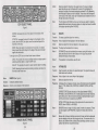
Name :
Name :
CREATE
Function:
Create a new object in the current area.
Response : A panel (see figure 4) will be displayed over the SHORTCUT icons showing
the type of object available .
Action:
RECT.
QUAD.
CREATE OBJECT PANEL
EDIT
Function :
Edit a specified object.
Response : A list of the existing object with in the current area will be displayed .
Action:
Select an object in the usual manner.
Response : A new bank of icons (see figure 5) will be displayed over the SHORTCUT
icons. The icons are split into five groups:
POINT: Alters the position of the point refered to in the INFO BAR.
This function only applies to non rectangular facets and pyramids. In
the case of facets all points may be moved .
Function :
24
Figure 4
Name :
GLOBAL
To bring up a list of the GLOBAL OBJECTS already defined within the
system .
Response : A list of predefined objects in the GLOBAL area will be displayed each
followed by a+ or - symbol. The + symbol denotes that the object is
included within the current area and - denotes it is not included .
Select an object type .
Response : The new object will be created within the View window.
Note :
Stretching and shrinking will also move the points in the object.
TURN: Rotates the object in the direction of the arrows on the icons
through 90 degrees.
25
Action:
Select an object for shading in the usual manner. To colour an object,
select the side you wish to shade with the cursor. By highlighting the
values to the right of the shaded rectangles numbered 1 to 6 (depending
on which type of object you wish to shade). These values will correspond
to the value of the shade, shown as 16 shaded boxes numbered 0 to 15 on
the right hand side of the panel.
Note :
The first shade is INVISIBLE and as such can be very useful for creating
special effects and saving time when sides of an object will never be visible
to the player by making them INVISIBLE.
SHRINK : Decreases the size of the object in the direction of the
arrows .
Name:
DELETE
STRETCH : Increases the size of the object in the direction of the
arrows. As with MOVE the object cannot be stretched beyond the
boundary of the area .
Function :
To delete a specified object from memory.
Response : A list of objects will be displayed in the Item Selector.
UNDO
:SLCT
OkAY
EDIT OBJECT PANEL
Figure 5
MOVE: Move the object in the directio n of the arrows . If an object
being moved hits another object or the edge of the area it is butted
against the obstruction.
Action:
Note 1:
ENTRANCES may also be deleted from memory using this function. Just
select the entrance from the Item Selector in the usual way and the
selected Entrance will be deleted.
Note 2:
This operation is irreversible, use with care!
Name :
ATTRIBUTES
Function :
View the position and status of a specified object. The object's status and
initial status can be altered .
To the right of the EDIT icons are three further icons as follows :
UNDO: This function will undo any editing made on an object prior to
selecting another object or using the OKAY icon.
SELECT: This provides the option to select another object for editing .
OKAY: Selecting this will commit all editing to memory and return to
the main screen once more.
Name :
SHADE (See Figure 6)
Function:
To shade a selected object.
Select an object from the Item Selector in the usual manner.
Response: The object will be deleted from memory.
Response : A list of object in the current Area will be displayed.
Action:
Response : A list of current objects will be displayed .
Select an object from the list.
Response : A Dialogue Box will appear showing various information about the selected
object - TYPE, NAME, SIZE, POSITION, CURRENT STATUS , INITIAL
STATUS.
CURRENT STATUS alters the status of the object between VISIBLE,
INVISIBLE and DESTROYED. An invisible object may be made visible at
some other point in the environment whereas a destroyed object is gone
until the environment is restarted using RESET.
INITIAL STATUS sets the status of the object when the environment is
RESET, either VISIBLE or INVISIBLE.
SHADE OBJECT PANEL
Figure 6
26
Note 1:
SENSORS have a range of (0-255), speed (in tenths of a second) . These
can be changed via ATTRIBUTES. A speed of 0 means that it will not
shoot.
Note 2:
Sensors do not have a direction and when off screen will not be obscured
by other objects so they can fire through walls etc. To overcome this it is
best to use a different form of check before activating a sensor such as a
collision with the floor around the Sensor.
27
THE FREESCAPE COMMAND LANGUAGE
The FREESCAPE system contains a simple language definition allowing functions
to be performed when certain conditions occur within the FREESCAPE environment.
The commands can be used in any of three places .
GENERAL CONDITIONS : These commands are executed every frame regardless
of the area currently occupied .
Note : General Condition number one is only called after a RESET.
LOCAL CONDITIONS : On ly the Local conditions defined in the currently occupied
are processed .These commands are executed each frame .
PROCEDURE CONDITIONS : These commands are only called from other
conditions by using the CALL command .
In the following list, P1 , P2 and P3 or V1 , V2 or V3 refer to parameters 1, 2 and 3
respectively. These can be either a literal number (referred to as P1 , P2 or P3} or a
variable number. In this case the contents of the variable will be used as the parameter
value . Parameters which must be Variables are referred to as V1 , V2 , V3 eg :
SETV(P1 ,V2)
shows that the second parameter must be a variable and the first is an absolute
value .
Optional parameters or commands are surrounded by square brackets [).
A list of the available commands follows along with a description of the required
parameters and their functions :
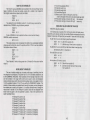
CONDITIONS
ADCV
AND
Format:
Class - Conditional Instruction
IF<XX>
AND
IF<XX>
THEN
commands ....
[ELSE
commands .... )
ENDIF
Function :
This command combines the result of two or more condition checking commands and
returns TRUE only if all of the specified checks are TRUE otherwise a FALSE result is
returned .
See also
IFEQ , IFLT, IFGT, THEN , ELSE , ENDIF, OR.
ANDV
Class - Variable Manipulation
AND VARIABLE
ANDV P1 V2
Format:
Function :
This command performs a logical AND on the absolute value P1 and Variable number
V2 and the result is stored in Variable number V2 . This instruction requires some
understanding of Binary and Logical functions.
See also
ORV, XORV.
Class - Variable Manipulation
ADD TO VARIABLE WITH CARRY
ADCV P1 V2
Format:
Function :
This adds the absolute value P1 to variable V2 . If the "carry" flag was set before the
execution of this instruct, one (the carry) is also added the result. If the result is greater
than 255 , then the value wraps around (becoming the would -be result minus 256) and
the "carry' flag is set.
See also
ADDV, SUBV, SBCV
ADDV
Class - Variable Manipulation
ADD TO VARIABLE
ADDV P1 V2
Format:
Function :
This adds the absolute value P1 to variable V2 . If the result is greater than 255, then
the value wraps around (becoming the would -be result minus 256) and the 'carry' flag
is set.
See also
ADCV, SUBV, SBCV
28
CMPV
Class - Variable Manipulation
COMPARE VARIABLE WITH ABSOLUTE VALUE
CMPV P1 V2
Format:
Function :
This command compares the value of P1 with V2 . The value held in the variable
specified as V2 is subtracted from the constant P1 . The Zero and Carry flags are set
accordingly. The contents of V2 remain unchanged . CMPV usually precedes an IFEO,
IFLT, IFGT instruction, as these act on the result of the comparison.
Example :
Variable 23 holds a count of objects collected in a game. No more than 5
objects are allowed to be carried at any one time. To see if an object may
be picked up would require a check to see if less than five objects are
carried . This could be performed with the following :
CMPV 5 23 (compare contents of V23 with 5)
IFLT
(if V23 is less than five)
THEN
(then)
<PICK UP OBJECT>
ELSE
< OBJECT CAN NOT BE CARRIED>
ENDIF
29
Class - Misc. Instruction
CALL
CALL PROCEDURE
CALL P1
Format:
Function:
This calls the Procedure number P1 . Processing will continue from the next instruction
in the current condition list when the procedure exits.
Note:
Do not call a procedure from within itself or the computer will lock up!
Class - Misc. Instruction
CROSS
CROSS P1 (either 0 or 1)
Format:
Function:
Turn the centre cross ON or OFF (0 is OFF and 1 is ON) . It defaults to 0 (ON) .
COLOUR
ELSE
Format:
Class - Misc. Instruction
Format:
COLOUR P1 P2
Function:
To change the 3D View window colour.
AMSTRAD CPC and C64
P1 refers to the colour number (0-3)
P2 refers to the pallette value (CPC 0-26)(C64 0-15)
SPECTRUM
P1 refers to the attribute type
0 INK
1 PAPER
2 BRIGHT
3 FLASH
P2 refers to the relavent attribute value
INK 0-7
PAPER 0-7
BRIGHT 0-1
FLASH 0-1
END
DELAY P1
Format:
Function:
This command halts all FREESCAPE functions for the specified time . The specified
time (P1) is in 50ths of a second .
Example :
DELAY 50 would halt execution for 1 second .
DESTROY
Class - Object Manipulation
DESTROY P1 [P2] (object[,area))
30
Class - Conditional Instruction
IF<XX>
THEN
commands ....
[ELSE
commands .... )
ENDIF
Function :
This command exists only as part of an IF<XX>ITHEN/ELSE/ENDIF combination . It
marks the start of commands to execute only if the result of a previous condition was
FALSE. The effectiveness of the command relies on the correct usage if the IF and
THEN commands . For any condition checking to work it is essential that the Condition
be preceded by an IF<XX> command and followed by a THEN and (if required) an ELSE
statement.
See also
THEN, ENDIF
Format:
Class - Misc. Instruction
DELAY
Format:
Function :
This command marks the given object as destroyed. If no area is specified then it is
assumed the object is in the current area .
Example :
IFSHOT 4 2
THEN
DESTROY 4 2
ENDIF
This simply asks if object 4 in area 2 has been shot and if so destroy object 4 in area 2.
Class - Misc. Instruction
IF<XX>
THEN
commands ... .
END
[ELSE
commands .... )
ENDIF
commands .. ...
Function :
This command exits command processing before the end of the command list is
reached, it allows the user to cut short the command execution on a particular condition
being TRUE or FALSE. Used in the above format, if the result of the condition is true
only the commands following the THEN statement will be executed and upon reaching
the END command the processor would stop processing the commands from this list.
Were there no END command the processor would continue executing from the
command following the ENDIF statement.
Note :
If used in a procedure then processing returns to the command after the
CALL instruction (in the condition list which called it) .
31
ENDGAME
Class - Misc. Instruction
Format:
ENDGAM E
Function:
This command serves to reset the environment. Th is can be executed on a particular
condition be ing TRUE or FALSE, ie if a counter being used to store game time reaches
zero then the game fin ishes and a RESET of the environment is performed .
Example:
In this example , variable 1O has been assigned to store game time .
CMPV 0 10
IFEQ
THEN
ENDGAME
ENDIF
ENDIF
Format:
Class - Cond itional Instruction
IF<XX>
THEN
commands ....
[ELSE
commands .... ]
ENDIF
FACTIVE
Format:
Class : Conditional Instruction (Interrogator)
IFACTIVE P1 [,P2) (P1 is an object number and P2 is an optional area
number)
IFACTIVE o[a]
THEN
commands .. ..
ENDIF
Function :
This command checks whether the selected object has been activated .
Example
IFACTIVE 4
THEN
INVIS 4
ENDIF
!hi.s .condition simply informs the system that if object 4 is activated then make object 4
inv1s1ble.
Note :
IF's cannot be nested !
IFCRUSH
Format:
Function :
This command terminates a conditional section . Upon reaching an ENDIF command ,
execution continues as normal before the IF<XX>fTHEN/ELSE combination . If the result
of a Condition is TRUE the commands after the THEN statement are executed and
those between the ELSE statement and the ENDIF are ignored . If the result is FALSE
the commands between the THEN and the ELSE are ignored and those between the
ELSE and the ENDIF are executed . In either case unless an END command has been
issued , command processing will continue after the ENDIF statement.
See also
IF<XX> Interrogators, THEN , ELSE
Class : Conditional Instruction (Interrogator)
IFCRUSH
THEN
commands ....
ENDIF
Function :
This Interrogator checks if the player occupies the same space as another object in the
same area. If so, a true is returned allowing the result of the check to be dealt with by a
THE.N/(ELSE)/ENDIF . con~truct . . A pos1t1ve result from the interrogator is usually
obtained .when .an object 1s VIS1bl1sed and that object's bounding cube encloses the
players view point. It can also be obtained when the view point is moved (via a GOTO)
to a space currently occupied by another object .
GOTO
Class - Vehicle Instruction
Format:
GOTO P1 [P2] (entrance (,area])
Function :
This command is used to allow player movement between the various defined areas
and/or entrances. Upon reach ing this command the player will be moved to the
ENTRANCE P1 in the AREA P2. If no area is specified the entrance is presumed to be
in the current area . If a new area is specified , command processing will cease at this
point otherwise normal command processing will continue.
Example :
IFSHOT 9
THEN
GOTO 1 2
ENDIF
The above example would be quite useful if it was desired that the player, upon
shooting a doorway (object 9) would then be transported to Entrance 1 in area 2.
32
IFEQ
Format:
Class - Conditional Instruction
IF EQUAL
IFEQ
THEN
commands ... .
[ELSE
commands .... ]
ENDIF
Function :
!his co.mma~d returns a true result if the preceding command had a zero result. This
instruction will normally follow a CMPV, ADDV, ADCV, SUBV or SBCV instruction and
act on the result of it. A THEN/(ELSE)/ENDIF construct should follow this instruction.
Note :
IF's cannot be nested !
33
IFFALL
Format:
Class - Conditional Instruction (Interrogator)
IF FALL
THEN
commands .. ..
[ELSE
commands .... ]
ENDIF
Format:
Class - Conditional Instruction (Interrogator)
IF GREATER THAN
IFGT
THEN
commands ....
[ELSE
commands .... ]
ENDIF
Format:
Function :
This command returns a true result if the preceding command had unset the "carry" and
the "ze.ro• flaQ. This instruction will normally follow a CMPV, ADDV, ADCV, SUBV or
SBCV 1nstruct1on and act on the result of it. A THEN/(ELSE)/ENDIF construct should
follow this instruction .
Note :
IF's cannot be nested!
IFSENSED
Format:
Function :
This command returns a true result if the preceding command had set the "carry" flag
and the "zero" flag unset. This instruction will normally follow a CMPV, ADDV, ADCV,
SUBV or SBCV instruction and act on the result of it. A THEN/(ELSE)/ENDIF construct
should follow this instruction .
Note:
IF's cannot be nested!
IFHIT
Class - Conditional Instruction (Interrogator)
IF LESS THAN
IFLT
THEN
commands ....
[ELSE
commands .... ]
ENDIF
Format:
Function :
This Interrogator returns true if the player has fallen past the safe fall height, specified
as FALL ABILITY in the SETUP Menu. The result of the check can then be dealt with by
a THEN/(ELSE)/ENDIF construct.
IFGT
IFLT
Class - Conditional Instruction (Interrogator)
IFHIT P1
THEN
commands ....
[ELSE
commands .... ]
ENDIF
Class - Conditional Instruction (Interrogator)
IFSENSED
THEN
commands ....
[ELSE
commands .... ]
ENDIF
Function :
This Interrogator returns a true if the player is occupying space that is detectable by a
sensor. The result of the interrogator is then acted on by a THEN/(ELSE)/ENDIF
construct placed after it. The effectiveness of a sensor can be set by altering it's
ATTRIBUTES.
IFS HOT
Format:
Function:
This command checks if an object P1 has been collided with (or walked on) . A true or
false is returned .
IFHIT 4
Example :
THEN
INVIS 4
VIS 5
ENDIF
In this condition the system checks if object 4 has been collided with . If it has then
object 4 becomes invisible and object 5 becomes visible. This could be used to remove
a door (object 4) and replace it with an open doorway (object 5) .
Note:
IF's cannot be nested!
See also
IFACTIVE, IFSHOT
34
Class - Conditional Instruction (Interrogator)
IFSHOT o (object)
THEN
commands ....
[ELSE
commands .... ]
ENDIF
Function:
Checks if you have just shot object (o) , returning a true or false .
IFTIMER
Format:
Class - Conditional Instruction (Interrogator)
IFTIMER
THEN
commands ....
[ELSE
commands ... .]
ENDIF
35
Function :
This command checks the TIMER flag, the com_mand returns a TRU~ result if a
timelapse of the amount specified in the setup section has passed , otherwise a FALSE
result is returned. Use the TIMER command to set TIMER frequency.
Class - Conditional Instruction (Interrogator)
IFVIS
Format:
IFVIS P1 [P2] (object [area])
THEN
commands ....
[ELSE
commands .... ]
ENDIF
Function :
This command checks the INVISIBLE flag in the status byte of OBJECT P1 in AREA P2 .
If no area is specified then the object is presumed to be in the current area. The
command returns a TRUE result if the specified object is VISIBLE , otherwise a FALSE
result is returned .
Example :
IFHIT 12
THEN
ELSE
(if object 12 (a door, say) is not hit then end)
END
ENDIF
(if it is then process the following)
IFVIS 4 (if object 4 (a switch , perhaps) is visible )
THEN
(then)
GOTO 1 5 (go to entrance 1 in area 5)
ENDIF
Example 2:
To check if an object is invisible, check to see if it is visible but act on a False outcome .
IFVIS 4
THEN
ELSE
(INSERT YOUR COMMANDS HERE)
ENDIF
Class - Object Manipulation
INVIS
INVIS P1 [P2]
Format:
Function:
Makes the object P1 in area P2 (optional) invisible . If the area is not specified , then
object P1 in the current area is made invisible.
Example :
IFSHOT 8
THEN
INVIS 9
ENDIF
A simple condition which states that if object 8 is shot then object 9 will become
invisible.
See also
INVIS, VIS
36
MODE
Class - Vehicle Instruction
Format:
MODE P1 (movement mode)
Function :
This command alters the current movement mode of the player, in the game. The player
is restricted to CRAWL, WALK, RUN , FLY1 and FLY2 . The value of the new mode P1
must be in the range of 0-4. Any value above this will be interpreted as 4 and any value
less than 0 will be interpreted as 0. The parameter, and what it represents is listed
below :
0 Crawl
3 Fly1
4 Fly2
1 Walk
2 Run
OR
Format:
Class - Conditional Instruction
IF<XX>
OR IF<XX>
THEN
commands ....
[ELSE
commands .. ..]
ENDIF
Function :
This command combines the result of two or more condition checking commands and
returns TRUE if any of the specified checks are TRUE otherwise a FALSE result is
returned .
See also
IF<XX>, THEN , ELSE , ENDIF, AND
ORV
Class - Variable Manipulation
Format:
ORV P1 V2
Function :
This command performs a logical binary OR on the two values specified, the value P1 is
ORed with the variable V2 and the result is stored in the variable. Flags are set
accordingly. This instruction requires some understanding of Binary and Logical
functions .
Example:
IFSHOT 8 (object)
THEN
ORV 2 21
ENDIF
This uses Bit 2 of Variable V21 as a flag to say that object 8 has been shot. Using this
method it is possible to use a Variable to store a number of ON/OFF flags . The flags
can be checked using the ANDV command .
Example :
ANDV 2 21
IFEQ
THEN
commands ....
[ELSE
commands .... ]
ENDIF
37
Class - Misc. Instruction
PRINT
PRINT mm xx yy (message and co-ordinates)
Format:
Function:
This command will PRINT the specified message (mm) from the message list at the X
(xx) and Y (yy) co-ordinates specified. These coordinates are in characters.
You must use a TEXTCOL command to set the colour.
Note:
REDRAW
Class - Misc. Instruction
Format:
REDRAW
Function :
This command will force an immediate redraw of the FREESCAPE view window. Any
objects whose status have changed since the last frame update will be displayed in
their new state .
SYNCSND
Class - Misc. Instruction
Format:
SYNCSND P1
Function :
This command will execute the specified sound P1 in sync with the next complete frame
update.The parameter P1 must be in the range 0-12, the sounds corresponding to the
value of the parameter are listed in the Appendix.
See also
SOUND
TEXTCOL
Class - Misc. Instruction
Format:
TEXTCOL cc (number of the desired colour)
Function :
This command is used to set the text and background colour for message printing . cc
calculated as shown:
SPECTRUM
(ink)+(paper x 8)+(64 if Bright required)+(128 if Flash required)
Class - Variable Manipulation
SETV
AMSTRAD CPC
(ink)+(paper x 4)
C64
(ink)+(paper x 16)
SETV P1 V2
Format:
Function :
This command sets the variable V2 to the value P1 .
Class - Misc. Instruction
SOUND
THEN
Format:
Format:
SOUND P1
This command will immediately perform the sound number P1. The parameter P1 must
be in the range 0-12, the sounds corresponding to the value of the parameter are listed
in the Appendix .
Class - Variable Manipulation
SBCV
SUBTRACT WITH CARRY
SBCV P1 V2
Format:
Function:
This subtracts the absolute value P1 from Variable V2 . If the •carry· flag was set before
execution of this instruction, then the result is decremented further by one.
See also :
ADDV, ADCV, SUBV
Class - Variable Manipulation
SUBV
SUBV P1 V2
Format:
Function:
This subtracts the absolute value P1 from Variable V2 .
See also
ADDV, ADCV, SBCV
38
Class - Condition Statement
IF<XX>
THEN
commands ....
[ELSE
commands ... .]
ENDIF
Function :
This command checks the status of the ZERO flag in the CCR. If the contents are TRUE
then the commands following the THEN statement are executed until either an ELSE or
ENDIF. statement is found. If an ELSE is found the commands following it are ignored
up until an ENDIF or the end of the command list. If an ENDIF is found then normal
command execution will continue with the following command . The THEN command is
the only command which examines the result of a condition, so an IF<XX>, ELSE,
ENDIF combination without a THEN command will produce incorrect results.
TIMER
Class - Misc. Instruction
Format:
TIMER P1
Funtion :
The TIMER instruction sets the frequency at which the timer flag is set, for detection by
an IFTIMER instruction. P1 is the interval time, and is in SOths of a second.
39
TOGVIS
Class - Object Manipulation
Format:
TOGVIS P1 [P2) (object [area])
Function:
This command will make an invisible object visible or a visible object invisible . If no
area is specified the object is presumed to be in the current area.
Class - Object Manipulation
VIS
VIS P1 [P2) (object [area))
Format:
Function :
This command makes an object visible .
See also
INVIS, IFINVIS, IFVIS, TOGVIS
Class - Variable Manipulation
XORV
XORV P1 V2
Format:
Function :
This command performs a logical binary EXCLUSIVE OR (EOR/XOR) o~ the two values
specified, the value P1 is ORed with the variable V2 and the result 1s stored _
in the
variable . Flags are set accordingly. This instruction requires some understanding of
Binary and Logical functions.
Example :
IFACTIVE 12 (object)
THEN
ORV 8 21
ENDIF
This uses Bit 3 (the fourth bit) of Variable V21 as a flag to say that ob_iect 12 has be~n
ACTIVATED OR DEACTIVATED. This allows us to toggle a flag using only one bit.
Possible uses include keeping track of switches which toggle between on or off. Using
this method it is possible to use a Variable to store up to eight of ON /OFF flags . The
flags can be checked using the ANDV command .
Example :
ANDV 8 21
IFEQ
THEN
commands ....
[ELSE
commands .... )
ENDIF
EXAMPLES
TO GO TO ANOTHER AREA
As an example we will use object 3 wh ich is our DOOR and object 4 which is our
DOORWAY. For simpl icity the doorway is a black RECTANGLE which is placed close
against a wall and the door is a red CUBE which has been ' flattened ' by the use of the
EDIT tools and placed close up in front of the doorway. The DOORWAY (rectangle)
should be set to INVISIBLE via the ATTRIBUTES function both on START STATUS and
PRESENT STATUS. We will use the IFACTIVE command to "open" the door and reveal
the doorway as follows. Enter the following conditiion as a LOCAL condition (create one
if required first) :
IFACTIVE 3
THEN
INVIS 3
VIS 4
ENDIF
Now experiment by pressing the SPACE BAR and position the cursor on the door
and press the A key. The door (object 3) should van ish and be replaced by the doorway
(object 4) .
Create a new AREA via the ADD AREA option and return to the Area 1 via the
GOTO AREA option . Now add the following cond ition commands in the same way as
above and enter the follow ing : (they can be tapped onto the end of the previous set of
intructions, or placed in a newly created local condition list in the same area.
IFHIT 4
THEN
GOTO 1 2
ENDIF
Now try walking towards the "doorway" until you coll ide with it. You will be
transported instantly to ENTRANCE 1 in AREA 2.
TO MAKE AN OBJECT VISIBLE OR INVISIBLE
As can be seen by the previous example, making objects van ish and reappear is
a very simple matter. If, for example, we wish an object (say object 3) to become
invisible when it is shot we would enter the following condition as a LOCAL condition
(create one if required) .
IFSHOT 3
THEN
INVIS 3
ENDIF
Shoot object 3 and see the effect.
TO MAKE A SOUND
Th is example will make a ping when picking up an object (object 5) .
IFACTIVE 5
THEN
INVIS 5
SYNCSND
ENDIF
40
41
HOW TO USE VARIABLES
The format for using a VARIABLE can be handled in the same way thr?ugh various
types of conditions. We could for example, arrange for a variable to be increased to
hold a higher value when an object is shot, as follows :
IFSHOT 3
THEN
ADDV 25 21
Thus adding 25 to the VARIABLE number 21. In a similar way a value can be
deducted from a VARIABLE using the following example :
IFSHOT 3
THEN
SUBV 15 21
To set a VARIABLE to hold a specified number we could use the following
GENERAL condition commands:
SETV 30 21
This same process can be incorporated into slightly .more complicated co~ditions
where we want to check the value of the variable and then 1f TRUE to set the variable to
hold another value as follows :
CMPV 0 21
IFLT
THEN
SETV 30 21
ENDIF
Thus if Variable 21 holds a value greater than 0, Variable 21 will be set to hold the
value 30.
MORE ABOUT VARIABLES
121 Current key presses (ASCII)
122 Interrupt counter Low
123 Interrupt counter High
124 Current Area/Data set
125 Ammo counter (if set to 0 the player cannot fire)
(if set to 255 gives infinite ammo else decremented per shot)
126 Font pointer starting at character 32 Low } ( for advanced
127 Font pointer starting at character 32 High
users only )
HANDLING VALUES GREATER THAN 255
TWO BYTE VALUES (0 -65535)
If, for example we set variable 10 to hold the game score, for display via an
Instrument as a 5 character number, two variables (bytes) are required to store this.
Variable 10 stores the LOW byte (first) and variable 11 stores the HIGH byte (last) .
To add 100 to the score the following would be performed :
ADDV 100 10 (Add 100 to variable 10)
ADCV
0
11 (Add the carry, if there is one to variable 11)
To add 300 to the score the 300 must be broken down to two bytes thus :
300 divided by 256 = 1 remainder 44
So to add 300 to our score :
ADDV
44 10
ADCV
1 11
And to subtract 300 from our score :
SUBV
44 1O (Take 44 from variable 10)
SBCV
1 11
(and take one with borrow (if there is one)
from variable 11)
The use of variables enables you to create a wide range of conditions, from the
very simple to the complicated . The system has 112 (0-11 .1) variables available !or use
by the COMMAND LANGUAGE . These variables are 8 bit storage areas (that 1.s they
can hold numbers in the range 0-255, which can be used to store and manipulate
various numerical values within the environment eg player score, fuel supply or a timer.
16 of the available Variables (112 to 127) are used by the FREESCAPE II system. The
contents of these variables are updated each frame by the system, and any changes to
the variables are so noted by the system ie. if a variable command were to change the
value stored in variable 112 (the Viewpoint X position (low)) the next displayed frame
would move the player to the new specified X position. A list of the contents of the
system variables follows:
112 Viewpoint X position Low
113 Viewpoint X position High
114 Viewpoint Y position Low
115 Viewpoint Y position High
116 Viewpoint Z position Low
117 Viewpoint Z position High
118 Viewpoint X Rotations (0-71 increments of 5 degrees)
119 Viewpoint Y Rotations (0- 71 increments of 5 degrees)
120 Viewpoint Z Rotations (0 -71 increments of 5 degrees)
42
43
USING THE COMPILER
APPENDIX
On some versions of the compiler you will be asked if you wish to load or save
data from tape or disc. Make your selection by pressing Tor D when prompted .
DEFAULT KEY CONTROLS
[IQ)
When the compiler is loaded you will be asked to insert the Destination Tape or
Disc. This is the medium on which your runable world will be located. Ensure that the
DESTINATION Tape/Disc is not A DATA or PROGRAM tape/disc. In the case of disc
users, the DESTINATION disc should be formatted normally, as instructed in your
computer user's manual.
Eventually, you will be asked to load the DATAFILE. You will be required to enter
the DATAFILE number (0-9), and instructed to insert your DATA tape /disc. This is the
tape/disc which contains your DATA. When ready, press a key.
When the data has loaded you will be required to replace the DESTINATION
tape/disc (a message will inform you of this) . When you have done so, press a key. The
DATA will then be copied to the DESTINATION tape/disc.
Finally, you will be asked if you require a border. If you have created a border to
be included in your runnable environment, press Y, otherwise press N.
In the case of the Spectrum and the CPC, these are straight screen dumps. The
border for the C64 must be in Advanced art studio format in multi -colour Lo-res
bitmapped mode.
Insert the DESTINATION tape/disc and when ready press a key.
The compiler will now save the final sections of data to the Runnable
DESTINATION tape/disc.
MOVE
BACK
FACE
FORWARD
SIDESTEP
LEFT
0
SIDESTEP
RIGHT
U-TURN
[fill
MOVE UP
(RISE/STAND)
[[I
MOVE DOWN
(FALUCROUCH)
rB
TURN
RIGHT
TURN
LEFT
ACTIVATE
OBJECT
[[I
LOOK
DOWN
fill
0
LOOK
UP
FIRE
~
TILT
RIGHT
[fill
TILT
LEFT
m
When the destination tape/disc is ready, press a key and the system will begin
saving part of the runner program.
If you typed a Y, then you will be required to insert the tape/disc with the border
image saved on it. Press a key when ready. The program will then ask for the name of
the border file. Type the full name then press enter. The border should then load. When
the border has loaded, you will then be asked to insert the DESTINATION tape/disc.
~
MOVE
FORWARD
r[.• SPACEf•
CTRL/SymbolShift - WHEN USED IN CONJUCTION WITH MOVEMENT KEYS,
IT WILL ACCELERATE THE MOVEMENT.
ESC/RUNSTOP/BREAK(ShiftSpace) - RESTART ENVIRONMENT (when in the
TEST screen it will take you back to the EDITOR)
The runnable world has now been created. Pressing a key at this point will exit
the compiler, resetting your machine.
You are free to distribute or sell the compiled runnable version of your
environment. All that is required, is that you mention on your product that it was created
using the 3D Construction Kit.
NOTE: It is an offence to sell or distribute copies of the 3D Construction Kit Editor
or any part of the Editor or accompanying data.
44
:oGGLE SIGHTS MODE/
MOVEMENT MODE
PALLETTE VALUES
AMSTRAD CPC
0
1
2
3
4
5
6
7
8
BLACK
BLUE
BRIGHT BLUE
RED
MAGENTA
MAUVE
BRIGHT RED
PURPLE
BRIGHT MAGENTA
9
10
11
12
13
14
15
16
17
GREEN
CYAN
SKY BLUE
YELLOW
WHITE
PASTEL BLUE
ORANGE
PINK
PASTEL MAGENTA
45
18
19
20
21
22
23
24
25
26
BRIGHT GREEN
SEA GREEN
BRIGHT CYAN
LIME GREEN
PASTEL GREEN
PASTEL CYAN
BRIGHT YELLOW
PASTEL YELLOW
BRIGHT WHITE
PALLETTE VALUES (Continued)
HINTS AND TIPS
SPECTRUM
INK & PAPER
0 BLACK
BLUE
2 RED
3 MAGENTA
4
5
6
7
GREEN
CYAN
YELLOW
WHITE
4
5
6
7
PURPLE
GREEN
BLUE
YELLOW
BRIGHT
0 NO
YES
FLASH
0 NO
YES
8 ORANGE
9 BROWN
10 LIGHT RED
11 GREY 1
12
13
14
15
C64
BLACK
WHITE
RED
CYAN
0
2
3
GREY 2
LIGHT GREEN
LIGHT BLUE
GREY 3
1. Save regularly.
2. Have blank formatted discs or blank tapes ready for saving data.
3. Always mention the Construction Kit release number and Registration
number in any correspondence.
4. Colour sides of objects that can never be seen to invisible to increase
performance .
5. Care should be taken when entering Conditions as an infinite loop could
be created effectively causing a crash. If in doubt save your data before
testing a procedure you are unsure of.
SOUND EFFECTS
0
1
2
3
-
Silence
Ping
Buzz
Fire
4
5
6
7
- Activate
- Bump
- Fall
- Fail
8910 11 -
12 - Door close
Bonus #1
Bonus #2
Bonus #3
Door open
RANGES OF ALLOWED VALUES
, object position X 0-127 - (one unit in object coordinates
= 64 units in world coordinates)
Object position Y 0-63
•
Object position Z 0-127
Object size X 0-127
Object size Y 0-63
Object size Z 0-127
Viewpoint X 0-8191 (128x64)
Viewpoint Y 0-4093 (64x64)
Viewpoint Z 0-8191 (128x64)
Numbers in conditions 0-255
Variables 0-127
which can store 0-255 (112 to 127 are system variables)
46
"
47
Other titles also available from Incentive Software
featuring the (j a~ l1~;U ~®
3 Dimensional Graphic System:
~
..... ...,...,...,
~~
I#~ lelJl'!r~
"Dazzlingly original" ACE
"Brilliant 30" ZZap
c;{~~a~
"Absolutely stunning"
~~~~~~~
c;{~~a~
~~~~~~
Computer+ Video Games
"Sheer involvement" 5 Star Game,
New Computer Express
<C~JW~
"Lasting intrigue" Amiga
~be ~rppt
"Castle Master II • The Sequel"
Format
Announcing ...
SUPERSCAPETM
VIRTUAL
REALITIES
The Virtual Reality System for
Graphic Workstations.
Software & Solutions from
-
DIMENSION
INTERNATIONAL
A DIVISION OF NEW DIMENSION INTERNATIONAL LTD.
Zephyr One, Calleva Park, Aldermaston, Berkshire RG7 4QW.
Telephone 0734 810077
48