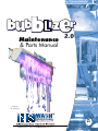
1
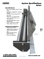
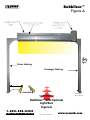
™ Maintenance & Parts Manual 2.0 US Patent No. 8,418,701 Rev. 05/13 Thank You! Thomas Sr. T T hanks for your confidence in NS Corporation and our vehicle washing products. If this is your first time as an NS equipment purchaser we welcome you to our family of customers dating back to 1961. hank you again if this purchase of equipment is the most recent in your loyal history as an NS customer. We truly appreciate your continued confidence in our company and it’s products. Your trust in us is the heart of our on-going success. I n today’s market every company, no matter the industry, must be Quality conscious. Our view of Quality goes beyond the delivery of equipment fabricated and assembled with exceptional care. In fact, the entire NS staff is dedicated to provide Quality products and Quality Customer Service. Every member of the NS team, including our worldwide Distributor organization, is committed to this sense of pride and professionalism in our efforts to assist you in achieving success in your vehicle washing business. W e want to hear your comments concerning your entire experience with NS during this most recent purchase. Please contact either one of us, or our Customer Service Director, with your report card on our performance. T hanks again for purchasing your equipment from NS. We appreciate your business. Thomas Ennis Sr. Chief Executive Officer 1-800-245-0350 F O R PA R T S & S E R V I C E Rev 05/13 • May 2013 www.nswash.com 3 Table of Contents Thank You!––––––––––––––––––––––– 3 Thomas Sr. Table of Contents––––––––––––––––– 4 System Specifications––––––––––––– 5 Options Operating Description–––––––––––– 6 Precautions Bubblizer™––––––––––––––––––––––– 7 Figure A Installation–––––––––––––––––––––– 8 Sequence Bubblizer™ Tank––––––––––––––––– 9 Isometric Views Wax Applicator–––––––––––––––––– 10 Orthographic Views Bubblecano Signs–––––––––––––––– 11 Optional Plumbing Manifolds––––––––––––– 12 Orthographic Views Plumbing Manifold–––––––––––––– 13 Float Switch Top Hatch-Restraint––––––––––––– 14 Pictures DEMA Injector––––––––––––––––––– 15 Detergent Injection Air Blower Assembly––––––––––––– 16 Steps 1-3 Electrical Schematics–––––––––––– 17 Sheet 1 Electrical Schematics–––––––––––– 18 Layout BOM 4 Optional LED Kit –––––––––––––––– 19 For RGB Changing Lights Optional LED Kit ––––––––––––––––20 Modes Optional LED Kit –––––––––––––––– 21 Safety and Connections Chemical Metering Board–––––––– 22 DEMA MixRite 57 250:1 DEMA MixRite––––––––––––––––––– 23 500 Series Click Chart DEMA MixRite––––––––––––––––––– 24 Proportional Injector DEMA MixRite––––––––––––––––––– 25 Specifications DEMA MixRite–––––––––––––––––––26 Technical Data DEMA MixRite––––––––––––––––––– 27 Installation DEMA MixRite––––––––––––––––––– 29 Adjustments DEMA MixRite–––––––––––––––––––30 Air Release Valve DEMA MixRite––––––––––––––––––– 31 On/Off System DEMA MixRite––––––––––––––––––– 32 Troubleshooting Manufacturers Limited Warranty– 33 Warranty Procedures––––––––––––34 Due to Continuous research NS Corporation reserves the right to upgrade or change at any time, specifications, or designs without notice and without incurring any obligations. Copyright © 2013 NS Corporation. 1-800-245-0350 F O R PA R T S & S E R V I C E Rev 05/13 • May 2013 www.nswash.com System Specifications Options Specifications • One 1.5 HP/ 120VAC/ 1 phase/ 7.4 Amp motor • All PVC internal Bubblizer™ plumbing manifold • Tank built with hinged top hatch for easy access • Mounts to 4”x 4” square anchor, 6”x 6” square NS bulkhead or to 4”Ø round arch • Standard White Powder-coated aluminum tank • Choice of yellow, blue, red lights • Vehicle Height Clearance 96” Equipment Options • Can be mounted to freestanding arches or equipment • LED Leg Mounted Vertical Signs • Custom Top Sign Package • Multi-color Lights • Dosing Pump (MixRite) 5 US Patent No. 8,418,701 1-800-245-0350 F O R PA R T S & S E R V I C E Rev 05/13 • May 2013 www.nswash.com Operating Description Precautions w/Optional Electrical Panel 1 Bubblizer™ control panel receives its 120VAC 1PH power from service source. (See sheet of panel schematic) 2 Activation of Bubblizer™ is the result of carwash controller sending 120 V AC signal to Bubblizer™ control panel. 3 4 Water to Bubblizer™ to be from fresh water source. Optional H-O-A switch on Bubblizer™ control panel should be on OFF when machine is not in service. Turn knob to A prior to car wash start up (Automatic.) 6 5 Fluid inside Bubblizer™ tank is composed of fresh water mixed with chemical. Source of mixture is from DEMA injector or the optional DEMA MixRite manifold. Fresh water flowing to and thru pump inlet causes pump to draw chemical from chemical container and pump mixture downstream to Bubblizer™ tank. A solenoid valve will open to allow fresh water through the DEMA injector/Dosing pump to maintain proper solution level in Bubblizer™ tank. 6 Air motor blows air through a perforated tube located inside the Bubblizer™ tank. Fluid inside Bubblizer™ tank will be bubblized and overflow through the discharge opening of Bubblizer™ tank and onto the vehicles below. When air pump stops pumping air into Bubblizer™ tank, no bubbles are made and discharged onto vehicles. 1-800-245-0350 F O R PA R T S & S E R V I C E Rev 05/13 • May 2013 www.nswash.com Bubblizer™ Figure A 7 Driver Side Leg Passenger Side Leg 20” min inside to inside Guide Rails US Patent No. 8,418,701 Bubblizer™ with Optional Light Bars Figure A 1-800-245-0350 F O R PA R T S & S E R V I C E Rev 05/13 • May 2013 www.nswash.com Installation Sequence Removable Air Motor Cover 930-0332 1.5HP AIR MOTOR 520-1621 PLC-056 POWER SUPPLY (optional) Multi Color LED Panel (optional) LED COVER (optional) 930-0331 LED BAR LIGHTS 24 volts DC RGB lights 360-1109 Standard Red 930-1108 Dema Manifold Vinyl Guard 930-2012 Top Bulkhead 4" Sq. Tubing 900-0393 8 Passenger Side Leg 4" Sq. Tubing 900-0336 Driver Side Leg 4" Sq. Tubing 900-0336 Bubblizer and Wax Applicator Arch US Patent No. 8,418,701 1-800-245-0350 F O R PA R T S DRAWN: GM & S E R V I C E Rev 05/13 • May 2013 TITLE: BUBBLIZER WITH www.nswash.com DWG. NO. Bubblizer™ Tank Isometric Views 11½” 7½” 14” 14” 9 US Patent 1-800-245-0350 F O R PA R T S & S E R V I C E No. 8,418,701 Rev 05/13 • May 2013 www.nswash.com Wax Applicator Orthographic Views 19” 3¾” LED LIGHT COVER TOP VIEW Hatch Door 900-8238 1.5HP AIR MOTORS (NOT SHOWN) INSIDE COVER 96” LED LIGHTS 19½” 10 11½” DEMA MANIFOLD 104” 96” END VIEW FRONT VIEW US Patent No. 8,418,701 1-800-245-0350 F O R DRAWN: RJM PA R T S DATE: 11/01/2011 & S E R V I C TITLE: E www.nswash.com DWG. NO. BUBBLIZER WITH WAX APPLICATOR Rev 05/13 • May 2013 ASM-03 Bubblecano Signs Optional Lighted Top Volcano Graphic Sign PN: BUBBLIZER-V Lighted Word Bubblecano Sign PN: BUBBLIZER-L Bubble-Curtain Light package PN: BUBBLIZER-R 11 Lighted Driver Side Bubblecano Sign PN: BUBBLIZER-D Lighted Passenger Side Bubblecano Sign PN: BUBBLIZER-P 1-800-245-0350 F O R PA R T S & S E R V I C E Rev 05/13 • May 2013 www.nswash.com Plumbing Manifolds Orthographic Views 12 US Patent No. 8,418,701 1-800-245-0350 F O R PA R T S & S E R V I C E Rev 05/13 • May 2013 www.nswash.com 1-800-245-0350 F O R PA R T S & S E R V I C E Rev 05/13 • May 2013 A No. 8,418,701 500-1401 430-1417 570-1626 570-1186 150-1220-5 2 3 5 6 7 8 7 6 7 6 1/2" PIPE PVC SCH 80 X 5" NIPPLE 1/2" BALL VALVE, PVC SCH 80 (T X T) DEMA INJECTOR 204B, 1/2"NPT BRASS ELBOW, 1/2" PVC SCH 80 (T X T) 1/2" X 1-1/2" CLOSE NIPPLE - PVC ALUMINUM 3/4" COUPLING DESCRIPTION THE INFORMATION CONTAINED IN THIS DRAWING IS THE SOLE PROPERTY OF N/S CORPORATION, ANY REPRODUCTION IN PART OR WHOLE WITHOUT THE WRITTEN PERMISSION OF N/S CORPORATION IS PROBIHITED. AL .5 COUPLING 1 ITEM NO. PART NUMBER US Patent B C D E F 8 1 1 1 2 4 1 QTY. 5 REVISION 2: 05/23/13 Replaced item 1 with 3/4” BY: MKTG 4 4 REVISION 1: 03/13/09 Replaced air motor with different manufacture BY: RJM Note: Item No. 1 is welded to the side of bubblizer tank wall 5 REVISION Scale: RJM NOT TO SCALE Aprvd by: JULY 08, 2008 Drawn by: Date: Chkd by: CORPORATION N/S 3 3 6 5 2 1 BUBBLE MACHINE SUPPLY MANIFOLD 2 BUBBLIZER MACHINE PLUMBING MANIFOLDS TITLE 2 2 3 2 7 2 1 SHEET: 1 of 1 PL-02 3 Drawing No.: 1 B C D E F Plumbing Manifold Float Switch 13 www.nswash.com Top Hatch-Restraint Pictures Hatch 900-8238 Braided Wire 200-2101 to hold top Hatch in Open Position. One at each end 14 Brass Float Valve 400-0206B Float 400-0208 1-800-245-0350 F O R PA R T S & S E R V I C E Rev 05/13 • May 2013 www.nswash.com I DEMA Injector Detergent Injection nline Chemical Injectors for injecting fluids or air into lines conveying liquid under pressure. The DEMA injector is a jet pump. A liquid under pressure, usually water, enters the injector and accelerates into a jet through the nozzle. This high velocity jet creates a vacuum, which causes fluid to be drawn through the suction tube and into the injector. The mixture then flows into a diverging (venturi) passage where pressure is recovered as the flow slows down. A portion of the energy of the water is imparted to the injected fluid so the reconverted pressure cannot be as high as the pressure supply. In effect the fluid is pumped into the water line; the reduction in pressure reflects the energy required to operate the “pump”. A minimum 35% pressure drop is required to create the vacuum. Advantages of the Injector Injectors have no moving parts, nothing to wear out or lubricate, resulting in extremely low maintenance. They are compact, needing no foundation or mounting bracket, and can be installed in any position. Injectors require no wiring, are self-priming and need no bleeding or filling. Injection rate is simple to set and can be quickly adjusted during operation. There is nothing to drain for seasonal shut down. General Information Standard C series have a molded Ryton knob with a stainless steel metering screw. For special requirements add the following suffixes to the model number. P: Special C20 stainless steel metering screw for highest corrosion resistance. S: Stainless steel knob for high pressures (over 700psi). T: Uses metering tip kit. 15 All injectors have a check valve to prevent back flow into the fluid container when there is no water flowing or while rinsing. An 8 ft. length of flexible vinyl suction tubing with a foot strainer is supplied. Application and Selection DEMA injector selection must be based on the water flow and pressure at the location where the injector is to be installed. DO NOT size the injector by pipe size. If these quantities are known, choose correct model from Tables. If theses quantities are not known, it is permissible to use spray nozzle rating at any pressure for selection. Once an injector has been matched to a spray nozzle system, it will continue to function regardless of fluctuations in line pressure, as the water flow will also fluctuate in proportion. Flow rating of 40 psi is the basis of the spray nozzle numbering system see glossary on and is, therefore, most frequently used. Lengthy piping, hose, or other restrictions resulting in pressure loss must be added to the rated pressure before selection. Injection Capabilities Every injector is supplied with a metering screw or metering tips (T) for setting injection rates within maximum and minimum capacities shown in Tables. Maximum injections of viscous fluids (above 75cps) can be increased by ordering the high induction metering knob kit, p/n 24-56. NOTE: Three nozzle bushings are supplied with each C series injector for precise sizing of the injector to water flow within the ranges shown. The maximum injection quantities can be doubled by using a nozzle bushing one size smaller than specified, but the pressure loss will be 50%. If your flow is in the lower third of the GPM range, order the next smallest injector to double the injection rate. 1-800-245-0350 F O R PA R T S & S E R V I C E Rev 05/13 • May 2013 www.nswash.com Air Blower Assembly Steps 1-3 Blower Mounting Plate 810-1608 Exploded Layout Install Blowers 16 Align Mounting Plate 2 8 4 Required Parts 1-800-245-0350 F O R PA R T S & S E R V I C E Rev 05/13 • May 2013 www.nswash.com 1-800-245-0350 F O R PA R T S & 7 T1 T2 T3 L1 L2 L3 S E R V I C E 2 R1 2 DPDT RELAY 7 #16 BLK AWG MTW #16 WHT AWG MTW # 8 AWG MAX, COPPER, 75°C Rev 05/13 • May 2013 1 #16 YLWAWG MTW successful manufacturing of vehicle wash equipment since 1967 SW2 3 A 3 H 4 4 BUBBLELIZER H O A Provide branch short circuit and ground fault protection per NEC 430-53C follow the main fuse or main circuit breaker selection. Main Disconnect Provided BY OTHERS 120 VAC Signal ACTIVATION #16 YELLOW AWG MTW DS 25 A 120 V / 1 Ø / 60 HZ N 8 3 9 10 #16 RED AWG MTW 8 R1 R2 6 1 R2 3 8 8 3 L VDC+ Manufactured by NS CORP Corporation Notes: 1) All wires lead to Terminal Blocks takes Terminal Block Number. 2) Use copper wire 75 degrees Celsius typical. VDC- N 7 10 A ,250 V NOTICE OF CONFIDENTIALITY 1.6 A, 250 V FU2 FUSE CHART R2 FU1 2 DPDT RELAY PS1 P1 BUBBLIZER PUMP #1 N1 N1 1 OF_3 THIS DOCUMENT CONTAINS PROPRIETARY INFORMATION THAT IS AND SHALL REMAIN THE PROPERTY OF NSWASH AND IS TO BE RETURNED IMMEDIATELY UPON REQUEST. ITS CONTENTS MAY NOT BE REPRODUCED, DISTRIBUTED, CIRCULATED, OR DISCLOSED TO THIRD PARTIES. RECIPIENT WILL NOT USE THIS INFORMATION FOR PURPOSES OTHER THAN INTENDED WITHOUT PRIOR WRITTEN CONSENT OF NSWASH Notes: a) FU1 & FU2 (Primary Fuses) to be Time Delay Rejection Type Littlefuse Class "CC", KLDR or Equal from Other Manufacturer. b) FU3 (Secondary Fuse) to be Time Delay, Supplementary Fuse, Littlefuse FLM or Equal from Other Manufacturer. 6 1 R1 N Electrical Schematics Sheet 1 17 US Patent No. 8,418,701 www.nswash.com successful manufacturing of vehicle wash equipment since 1967 18 Manufactured by NS CORP Corporation NOTICE OF CONFIDENTIALITY F O R 1-800-245-0350 PA R T S & S E R V I C E Rev 05/13 • May 2013 3 OF_3 THIS DOCUMENT CONTAINS PROPRIETARY INFORMATION THAT IS AND SHALL REMAIN THE PROPERTY OF NSWASH AND IS TO BE RETURNED IMMEDIATELY UPON REQUEST. ITS CONTENTS MAY NOT BE REPRODUCED, DISTRIBUTED, CIRCULATED, OR DISCLOSED TO THIRD PARTIES. RECIPIENT WILL NOT USE THIS INFORMATION FOR PURPOSES OTHER THAN INTENDED WITHOUT PRIOR WRITTEN CONSENT OF NSWASH Electrical Schematics Layout BOM www.nswash.com Optional LED Kit For RGB Changing Lights 19 1 Specifications Working temperature :-20~60ºC Supply voltage: DC 5~24V Product size: L 210 x W 40 x H 30 mm Package size: L 215 x W 45 x H 35 mm Changing mode: 29 modes Remote distance: >=100m Color depth: Max.256 level per RGB. Bright adjust: 8 levels Speed adjust: 8levels Net weigh: 200g Gross weight: 230g Output: Three CMOS drain-open output Max output current: 8A per channel 1-800-245-0350 F O R PA R T S & S E R V I C E Rev 05/13 • May 2013 NOTE: When programing more than one unit in a tunnel, Turn off power on all units except the one being programed to avoid sending commands to other units. www.nswash.com Optional LED Kit Modes 2 Features • • • • Controlled by remote controller . Input Voltage range: DC 5~24V 3-channel RGB full color control, max output current 8A per channel. 29 modes of changing, such as static, gradual, jumpy etc., with color depth max 256 levels per RGB. • Speed and brightness of each mode is adjustable separately from 1-8 levels. • Can rest at current color and color depth. • Can restore to default settings by pressing RESET button. 3 The function of each button is as follows: Button “ON/OFF”: Turn on/off the controller. Button “PAUSE/2”: Keep current status, press it again, keeps changing Button “MODE+/M+/3”: Enter the next mode. Button “MODE -/M -/4”: Return to the previous mode. Button “BRIGHT/B/6”: Adjust LED brightness levels. (1~8 levels) Button “SPEED/S/5”: Speed up/down color changing. (1~8 levels) Button “RESET”: Restores default status if pressed over 3 seconds. 20 4 Modes No. Status No. Status 1 2 3 4 5 6 7 8 9 10 11 12 13 14 15 Static Red Static Green Static blue Static Yellow Static Purple Static Cyan Static White Tri-color Jumpy Changing 7-color Jumpy Changing Red Stroboscopic-changing Green Stroboscopic-changing Blue Stroboscopic-changing Yellow Stroboscopic-changing Purple Stroboscopic-changing Cyan Stroboscopic-changing Changing 16 17 18 19 20 21 22 23 24 25 26 27 28 29 White Stroboscopic-changing Changing Tri-color Gradual changing 7-color Gradual changing Red-green gradual changing Green-blue gradual brighten & fade Red-blue gradual brighten & fade Red gradual brighten & fade Green gradual brighten & fade Blue gradual brighten & fade Yellow gradual brighten & fade Purple gradual brighten & fade Cyan gradual White gradual Modes Cycle 1-800-245-0350 F O R PA R T S & S E R V I C E Rev 05/13 • May 2013 www.nswash.com Optional LED Kit Safety and Connections 5 Advantages: • Matched with the RGB flexible strip, easily control the colors. • Color modes: Multi function, 29 kinds of color changing modes. • When changing color modes such as 3/7 color gradual/ jumpy changing, the speed and the brightness are adjustable in 1 to 8 step levels. • In single color modes: the brightness is 1-8 steps level adjustable • Press the button Pause to keep the current color • Wide voltage input: 5V-24V DC • Memory function: when you turn off the power supply, the controller can remember the modes, you do not need to choose the modes again. 6 Safety Information: • Please don’t install this controller in lightning, intense magnetic, humid and high-voltage fields. • To reduce the risk of component damage and fire, make sure connections are correct with no short circuits before connecting to power . • Check if the voltage and power adapter suit the controller and if anode or cathode definition is the same as the controller’s. • If device has been damaged during transport, don’t take any action without contacting your supplier. If being used properly in accordance with the instruction, and quality problems occur, please contact local supplier too, we provide free repair or replacement services. 21 7 Connection Diagram 1-800-245-0350 F O R PA R T S & S E R V I C E Rev 05/13 • May 2013 www.nswash.com Chemical Metering Board DEMA MixRite 57 250:1 to Bubblizer™ Tank DEMA MixRite 570CW 520-2029 3/4” In-Line Filter 460-0075 22 Pressure Regulator Adjustment Percent Ratio 400-1266 3/4” Solenoid Valve 570-1127-C Mounting Panel 1/8”x15”x22” 630-1037 Ball Valve 3/4” US Patent No. 8,418,701 570-1182 1-800-245-0350 F O R PA R T S & S E R V I C E Rev 05/13 • May 2013 www.nswash.com DEMA MixRite 500 Series Units All Information is for all 500 Series units models 569 through 575 DEMA MixRite 500 Series Click Chart Click Chart 1 Click is .06 Gallons 1 Gallon is 16 Clicks Clicks Gallons Gallons Clicks 1 2 5 10 15 16 20 24 30 35 40 45 50 60 75 90 105 120 135 150 160 175 0.06 0.12 0.31 0.61 0.92 0.98 1.23 1.47 1.84 2.15 2.45 2.76 3.07 3.68 4.60 5.52 6.44 7.36 8.28 9.20 9.81 10.73 0.25 0.5 1 1.25 1.5 1.75 2 2.5 3 3.5 4 4.5 5 5.5 6 6.5 7 7.5 8 9 10 11 4 8 16 20 24 29 33 41 49 57 65 73 82 90 98 106 114 122 130 147 163 179 Common Injection Chart Percentage Ratio Oz/Gallon 0.10% 0.25% 0.33% 0.50% 0.66% 0.75% 0.80% 0.90% 1.00% 1.20% 1.30% 1.40% 1.50% 1.60% 1.70% 1.80% 1.90% 2.00% 2.25% 2.50% 2.75% 3.00% 3.50% 4.00% 4.50% 5.00% 6.00% 7.00% 8.00% 9.00% 10.00% 1-800-245-0350 PA R T S & S E R V I C E 0.13 0.32 0.42 0.64 0.84 0.96 1.02 1.15 1.28 1.54 1.66 1.79 1.92 2.05 2.18 2.30 2.43 2.56 2.88 3.20 3.52 3.84 4.48 5.12 5.76 6.40 7.68 8.96 10.24 11.52 12.80 23 Matt Brandt Sales Engineer-Industrial Products [email protected] 314-809-6500 DEMA Engineering Co. 10020 Big Bend Blvd. St. Louis, MO 63122 F O R 1000:1 400:1 303:1 200:1 152:1 133:1 125:1 111:1 100:1 83:1 77:1 71:1 67:1 63:1 59:1 56:1 53:1 50:1 44:1 40:1 36:1 33:1 29:1 25:1 22:1 20:1 17:1 14:1 13:1 11:1 10:1 Rev 05/13 • May 2013 www.nswash.com DEMA MixRite Proportional Injector ® User Manual Injector The MixRite isPropotional powered by water flow, with minimal loss of pressure. The water engine powers the proportioning unit. No Bomba de dosificación proporcional external power is required. Pompe àunit Dosage Proportionnel The proportioning injects liquid additives in direct relation to the amount of water that passes through the motor and injects the additives into the water system. The water engine action: The suction and proportioning unit is built from a piston connected to the water engine, from which it derives its movement. The piston moves within a cylinder with a non-return valve. The movement of the piston within the cylinder causes the water to be injected with the required liquid additive to be drawn through a hose inserted into a container. It is possible to regulate the supply ratio between the additive and the water passing through the injector in models: 570(CW/CL/PVDF),572(CW/CL/PVDF),574CL, 571(CW/CL/PVDF),573(CW/CL/PVDF),575CL. In model 571 Green the dosing is predetermined and can not be changed. In models 576IN, 578IN, 577IN, 579IN the drawn additive is transferred through a inlet bypass directly into the main water line, without contact with the water engine. 24 Manual del Usuario Manuel Utilisateur 10001 Air release valveManuel User Water engine English p. 2 - 1 0 Espan p. 1 1 - 2 0 Français p. 2 1 - 3 0 Water outlet www.demaeng.com E-mail: [email protected] Water inlet Edition 5.10 I-870 Rev F - 36742 Page 1 of 30 Suction unit with adjustable proportional dosing I-870 Rev F - 36742 Page 2 of 30 1-800-245-0350 F O R PA R T S & Additive suction tube S E R V I C E Rev 05/13 • May 2013 www.nswash.com DEMA MixRite Specifications > < 1-800-245-0350 F O R PA R T S & S E R V I C E Rev 05/13 • May 2013 25 www.nswash.com DEMA MixRite Technical Data Technical Data MixRite operates in the following conditions: From a minimum flow rate of 20 L/H (5.3 Gal/H) and up to 2,500 L/H (660 Gal/H) Temperature not lower than 4°C (39°F) and not higher than 40°C (104°F) Water pressure between 0.2 Bar to 8 Bar (2.9 to 120 PSI) The additive may be added to the water flow according to the required dosing percentage: 0.3% to 2% in models: 570(CW/CL/PVDF), 571(CW/CL/PVDF), 576IN, 577IN. 0.4% to 4% in models: 572(CW/CL/PVDF), 573(CW/CL/PVDF), 578IN, 579IN. 3 % to 10% in models: 574CL,575CL Fixed dosage 0.8 % in models: 571 Green Water pressure loss: Pressure loss in the lower flow rates 0.1 Bar and in the higher flow rates up to 1 Bar. Models with 0.3%-2%: from 0.1 Bar up to 1 Bar in proportion to the water flow Models with 0.4%-4%: from 0.2 Bar up to 1.2 Bar in proportion to the water flow Models with 3%-10%: from 0.5 Bar up to 1.8 Bar in proportion to the water flow The MixRite inlet and outlet are ¾" BSPT male thread. The additive tank should be placed beneath the MixRite. 26 Mounting the MixRite 1. Prepare the MixRite site. The MixRite intake and outlet must reach the intake and outlet pipes. The MixRite must be positioned above the liquid additives container. 2. Screw the MixRite bracket onto a wall or any stable vertical base. 3. Press the MixRite onto the bracket. The nipples on the MixRite must click into the holes in the side of bracket. I-870 Rev F - 36742 Page 3 of 30 1-800-245-0350 F O R PA R T S & S E R V I C E Rev 05/13 • May 2013 www.nswash.com DEMA MixRite Installation Installation of the MixRite Installing the MixRite on a Direct Line (in line) 1. Install onto the water line using swivel connectors and ensure that the water flows into the MixRite in the direction indicated by the arrows printed on the MixRite. 2. Install a 50-75 mesh (250-300 micron) filter between the valve and the injector intake. 3. Valves have to be installed at the water line entry and exit; in order to stop the pump's action – you should close the Valve at the entry point. 4. Position the drawing pipe into the additive container. Ensure that the suction pipe filter is set several millimeters above the container’s bottom. Check to ensure that the suction pipe is not bent or folded. Install the MixRite on a Direct Line (In Line) 27 Correct Installation Incorrect Installation I-870 Rev F - 36742 Page 4 of 30 Rev 05/13 • May 2013 Installing the MixRite on a Bypass line (off line) Where water is supplied at a higher flow rate, than the working flow rate of the injector or where the injector isn’t needed for continuous operation, the MixRite must be installed on a bypass line. The bypass provides the possibility to close the operation of the injector while water continues to flow through the line. 1. Install onto the water line using swivel connectors and ensure that the water flows into the MixRite in the direction indicated by the arrows printed on the MixRite. 2. Install a 50-75 mesh (250-300 micron) filter between the valve and the injector intake. 3. Valves have to be installed at the bypass entry and exit and on the main water line. 4. Position the liquid additive container beneath the injector. Check to ensure that the suction pipe is not bent or folded. Position the drawing pipe into the additive container. Ensure that the suction pipe filter is set several millimeters above the container’s bottom. Install the MixRite on Bypass Line (Off Line) 28 I-870 Rev F - 36742 Page 5 of 30 1-800-245-0350 F O R PA R T S & S E R V I C E Rev 05/13 • May 2013 www.nswash.com DEMA MixRite Adjustments A MixRite Bypass installation 2.5 (M/h) including mobile fertilizer solution tank Chocking valve Main Water Pipe Reservior Tank Operating valve Adjusting the MixRite Every stroke of the MixRite moves a predetermined volume of water with a predetermined volume of liquid additive. To adjust the volume of the liquid additive in models 570(CW/CL/PVDF), 572(CW/CL/PVDF), 571(CW/CL/PVDF), 573(CW/CL/PVDF), 576IN, 578IN, 577IN, 579IN: 1. Remove the upper U–latch from the Proportioning Lock Nut. 2. Preset the amount of additives according to the Percentage to Water Scale that is found on the proportioner. • Turn the proportioning Adjuster counter clock-wise to increase the amount of additives. • Turn the Proportioning Adjuster clock-wise to decrease the amount of additives. The marking on the scale indicates the % of additive out of the total water flowing through the injector. 3. Turn the proportioning Adjuster slightly, until the U-latch holes of the Proportioning Lock Nut align with the notches in the proportioner. 4. Push the U-latch into the U-latch holes of Proportioning Lock Nut until it is firmly in place. I-870 Rev F - 36742 Page 6 of 30 1-800-245-0350 F O R PA R T S 29 & S E R V I C E Rev 05/13 • May 2013 www.nswash.com DEMA MixRite Air Release Valve In models 574CL, 575CL there is no Ulatch and the adjustment is done by turning the adjustment sleeve to the desired %. In models 571 Green there is no possibility to adjust the dosing percentage it is predeterment by the injector model (see page 3) U-latch To decrease To increase DO NOT REMOVE THE LOWER U-LATCH !!! (For maintenance purpose only) Rinsing and Cleaning the unit After pumping • Rinse the unit by pumping clean water from the additives container. • Wash the external surface of the unit with clean water. Warning: During pumping, ensure that the additive container is not completely empty. 30 Air-release Valve In models: 571 Green, 570(CW/CL/PVDF), 572(CW/CL/PVDF), 574CL, 576IN, 578IN. After initial operation of the MixRite, apply pressure to the cap (the air release valve) for several seconds to open valve that allows trapped air to escape. This air release is accompanied by a slight loss of water. Release the pressure on the cap to close the valve. Press to release air Air is released with a small amount of water I-870 Rev F - 36742 Page 7 of 30 1-800-245-0350 F O R PA R T S & S E R V I C E Rev 05/13 • May 2013 www.nswash.com DEMA MixRite On/Off System On/Off System In Models: 571(CW/CL/PVDF), 573(CW/CL/PVDF), 575CL, 577IN, 579IN. ON position – the Knob should be in its high position, the injector is working & pumping. OFF position – The knob is turned and pushed down to the cap, the water flow the injector continuous without the pumping action. To Turn the dosage unit off and allow the free flow of water through the MixRite: A: The handle must be turned and pushed in so that it is in the close state.(see 1). To Turn the dosage unit on and allow the pumping action MixRite: B: The handle must be turned and pulled out so that it is in the opened state. (see 2). 31 Diagram 1 Diagram 2 In injectors with On/Off knob there is no air-release valve. It is highly recommended to use the On/Off knob when the additive container is empty or there is no need at all in the additive but the water flow should continue. I-870 Rev F - 36742 Page 8 of 30 1-800-245-0350 F O R PA R T S & S E R V I C E Rev 05/13 • May 2013 www.nswash.com DEMA MixRite Troubleshooting Troubleshooting Problem MixRite does not operate Check Check that the intake and outlet valves are open Check that the water filter isn’t clogged Check that water is flowing in the line Check that springs are not broken Open pump lid & remove piston Check that cylinder is not scratched Check that piston seals are not damaged MixRite does not draw Dismantle the suction pump and check the suction seal for damage The MixRite makes scratching noises Check if there is liquid in the additive container Check if suction pipe is immersed and not folded Check suction filter to see if it is blocked and if it is immersed in the additive tank 32 Solution Open the valve Clean the filter Open main and outlet valve Change the broken spring Change cylinder Change the seals Change the suction seal Add liquid to the container Straighten or change the pipe Clean and rinse suction filter, Fill liquid into tank to cover filter Correct installation will prevent damages and malfunctions of the MixRite It is strongly recommended to install a back flow preventor before the injector on the main water line. A vacuum release unit should be installed at the outlet of the MixRite in order to prevent undesired suction of additive when the water line is draining. A master valve must be installed before the injector, to be opened only for the operation of the injector to prevent water hammer damage to the injector. I-870 Rev F - 36742 Page 9 of 30 1-800-245-0350 F O R PA R T S & S E R V I C E Rev 05/13 • May 2013 www.nswash.com Manufacturers Limited Warranty Government and rental divisions EXPRESSED WARRANTY: N/S Corporation’s manufactured vehicle wash equipment is guaranteed for one (1) year commencing the first day following installation, or thirty (30) days from the original invoice date, which ever occurs first. Equipment not manufactured by N/S Corporation and electrical parts are guaranteed for ninety (90) days. The equipment is guaranteed against manufacturing defects on material and workmanship, which develop in the service for which it was designed, provided that the equipment is installed and used in accordance with all applicable instructions and limitations as issued by N/S Corporation. Pursuant to the above expressed warranty, N/S Corporation at its sole discretion, will repair goods or replace defective materials, free of charge excluding labor, provided that such goods or materials are returned as specified by N/S Corporation. N/S Corporation does not warrant: (1) transportation, installation, adjustment, or other expenses which may arise in connection with such equipment or parts; (2) site related/ operation based problems; (3) damage due to accident; (4) damage due to misuse, negligence, or overloading; (5) lack of proper maintenance; or (6) maintenance items, including but not limited to lubricating grease/oils, filters, cloth, materials, bearings, rollers, etc. nor any items therein which show signs of neglect; (7) damage due to non-N/S equipment or unauthorized personnel. Repairs and service provided by unauthorized N/S personnel voids warranty. 33 LIMITED LIABILITY: N/S Corporation shall not be liable (1) for any incidental, special, consequential, or exemplary damages; (2) for commercial loss; (3) for inconvenience; or (4) for any service not expressly provided for herein related to or arising from the vehicle wash equipment. N/S Corporation makes no further warranties and no implied warranties of merchantability or fitness for a specific purpose. All terms and conditions apply unless otherwise specified in the contract. This warranty given in lieu of all other expressed warranties on the part of the Manufacturer, Distributors, or Dealers. No Dealer or Distributor (nor any agent, representative or employee thereof) is authorized to extend or enlarge this warranty. If there are any questions regarding these procedures or you need additional assistance, please contact our Director of Customer Service at (310) 330-1250. Copyright 2013 NS Corporation. All rights reserved. No part of this work may be reproduced or transmitted in any form or by any means, electronic or mechanical, including photocopying and recording, or by any information storage of retrieval system, except as may be expressly permitted by the 1976 Copyright Act. NS has the right to change or modify this limited warranty without notice. F: CS-008 1-800-245-0350 F O R PA R T S & S E R V I C E Rev 05/13 • May 2013 Revision Date: 9/26/13 www.nswash.com Warranty Procedures 1 Before commencing any warranty work, the N/S Customer Service Department must be contacted and advised that a problem was encountered, which location, and an estimate must be given for any labor cost. The Customer Service Department will then advise the customer as to what action is to be taken. 2 If replacement parts are required, the Customer Service Department will advise the customer where the needed parts can be obtained. 3 All of parts supplied under warranty will be shipped via UPS ground by N/S Corporation. If a more expeditious means are requested, the customers will incur the extra charges. 34 4 Returned Good Authorization (RGA) will be issued by the N/S Customer Service Department at the time that credit for the replacement parts is requested. All parts returned under an RGA number must be returned within 20 days, freight prepaid and the RGA number must be plainly visible on the outside of the packaging. 5 6 No Credit will be issued for motors or reducers that do not have the original name plates affixed. If there are any questions regarding the clarification of these procedures, this may be directed to the N/S Director of Customer Service at (800) 782-1582 1-800-245-0350 F O R PA R T S & S E R V I C E Rev 05/13 • May 2013 www.nswash.com 35 1-800-245-0350 F O R PA R T S & S E R V I C E Rev 05/13 • May 2013 www.nswash.com ™ 235 West Florence Avenue Inglewood, California 90301 1-800-782-1582 Parts or Service 800-245-0350 310-330-1238 310-330-1275 310-412-2367 fax Due to Continuous Research NS Corporation Reserves the Right to Upgrade or Change at Any Time, Specifications, or Designs Without Notice and Without Incurring Any Obligations. Copyright © 2013 NS Corporation.