1
SIDEREAL TECHNOLOGY
Operations Manual
Copyright© Sidereal Technology, 2004, 2005, 2006, 2009
Draft Version 1.1
Revised October 20, 2009
http://www.siderealtechnology.com/
1 of 236
Revision History for the OPERATIONS Manual
7
THE BIG PICTURE (READ THIS FIRST!)
8
1 FEATURES
9
1.1 BASIC BUILT-IN STANDALONE CONTROLLER FEATURES
10
1.2 ADDITIONAL FEATURES AVAILABLE USING THE FREE SiTtechEXE PROGRAM
12
1.3 COMPARISON BETWEEN STEPPER SYSTEM AND SERVO SYSTEM
13
1.4 SAFETY
14
1.5 SOFTWARE VERSIONS
14
2 OPERATION WITHOUT A PC
2.1 ALT-AZ DRAG AND TRACK MODE
2.1.1 Setting Up the Drag and Track Mode
2.1.2 Operation of Drag and Track Mode
2.1.3 Review of Alt-Az Initialization options
2.2 ALT-AZ SLEW AND TRACK MODE
2.3 EQUATORIAL MODE
2.3.1 Setting Up the Equatorial Mode
2.3.2 Operation of the Equatorial or Tracking Platform Mode
2.3.3 Observing the Crab Pulsar
2.4 USE WITH AN ARGO NAVIS™:
2.4.1 Setting up the Argo Navis™:
2.4.2 Setting Up the SiTech Controller for Argo Navis™:
2.4.3 Operation of the Argo Navis™:
2.5 USE WITH SKY COMMANDER™
2.5.1 Set Up SiTech Serial Port
2.5.2 Setting up SiTech for Sky Commander™
2.5.3 Setup Sky Commander™ for use with SiTech Controller
2.5.4 Initial Setup and Testing of Alt-Az Sky Commander™ with SiTech
2.5.5 Starting and Using SiTech with Sky Commander for Alt-Az Ops
2.5.6. Initial Setup and Testing of Equatorial Sky Commander™ with SiTech
2.5.7 Starting and Using SiTech with Sky Commander™ for Equatorial Ops
15
15
16
17
18
20
21
21
21
22
23
24
24
24
25
25
26
26
28
29
30
30
3 OPERATION WITH A PC
3.1 SOFTWARE USED
3.2 LOADING THE SOFTWARE
3.3 STARTING THE SiTech TELESCOPE DRIVER SiTechEXE
3.4 CONFIGURING THE SiTech TELESCOPE DRIVER
4.1 BASIC FEATURES
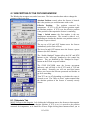
4.2 COMMON AREA OF THE SiTechEXE SCREEN
4.2.1 STOP/Stopped (Tracking/Startup Tracking)
4.2.2 Message Window
4.2.3 RA/SHA/Dec windows
4.2.4 Focuser and Rotator Control Buttons (Advanced Feature)
4.3 TABBED SECTIONS OF THE SiTechexe WINDOW
4.3.1 Scope Tab: Main SitechEXE screen
4.3.2 Virtual Handpad
31
31
31
33
33
36
36
36
37
38
38
39
39
39
2 of 236
4.3.3 PointXP Button (ADVANCED FEATURE)
4.3.4 Park/UnPark/SetPark
4.4 NUMBERS TAB
4.5 FEATURES TAB
4.5.1 Polar Align: (ADVANCED FEATURE)
4.5.2 Do GEM Flip
4.5.3 Run Script: (ADVANCED FEATURE)
4.5.4 Controller Stuff: (ADVANCED FEATURE)
4.5.5 PEC Control (ADVANCED FEATURE)
4.5.6 Offset Tracking Rates (ADVANCED FEATURE)
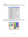
4.5.7 Colors
4.6 GoTo/SYNC TAB
4.6.1 Scroll FileName
4.6.2 Select File Line
4.6.3 Star and Messier buttons
4.6.4 NGC and IC windows
4.6.5 GoTo and Sync Buttons
4.7 INITPOINT WINDOW
4.8 OFFSET INITS VS. CAL STAR INITS
4.8.1 Offset Inits
4.8.2 Cal Star inits
4.9 THINGS TO KEEP IN MIND
4.9.1. First Two Stars
4.9.2. GEM Special Instructions
4.9.3. Single Star Init
4.9.4. Watch your Scope Latitude
4.9.5. Know when to use Cal Star Init Points and when to use Offset Inits
4.9.6 Initializinging the Scope on a Fixed Object
4.10 CONFIG TAB
4.11 SiTechEXE CONFIGURATION SCREENS
4.11.1 Setup “Telescope Info” tab
4.11.2 Setup “Mount Info” Tab
4.11.3 Setup “Scope Encoders” Tab
4.11.4 Setup “Miscellaneous” Tab
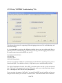
4.11.5 Setup “ASCOM & Troubleshooting” Tab
4.11.6 Setup “Focuser and Rotator” Tab: (ADVANCED FEATURE)
4.11.7 Setup “Potentiometers” Tab: (ADVANCED FEATURE)
4.12 CONNECTING WITH YOUR PLANETARIUM SOFTWARE
4.13 EQUATORIAL AND GEM INVERT BUTTON SETUP
4.13.1 Northern Hemisphere Setup
4.13.2 Set Up and Operation in Southern Hemisphere
5 ADVANCED FEATURES
5.1 SCOPE TAB
5.1.1 PointXP Mount Modelling
5.1.2 Aligning PointXP Using PlateSolveXP
5.1.3 Scripted PlateSolveXP Operations
5.1.4 Scripted PxP Setup and Configuration
5.1.5 Scripted PxP Operations Procedure
3 of 236
40
40
41
43
43
43
44
45
46
47
48
49
50
50
50
50
50
51
53
53
53
54
54
54
55
55
55
56
57
58
58
59
61
66
68
69
71
71
72
72
72
74
74
74
78
80
82
83
5.1.6 PXP Tips and Tricks and Lessons Learned
5.1.7 Aligning PointXP Using other Plate Solvers
5.2 FEATURES TAB
5.2.1 Polar Align
5.2.2 Run Script
5.2.3 Making Scripts
5.2.4 Using the Handpad to control a Script:
5.2.5 Controller Stuff
5.2.6 PEC Control
5.2.7 Simple PEC Recording Session
5.2.8 PEC Playback Session
5.2.9 PEC Complex Recording Session
5.2.10 PEC More Info
5.2.11 Periodic Error Correction with PemPro
5.2.12 Offset Tracking Rates
5.2.13 Clock Calibration
5.2.14 Handpad SlipMode
5.3 Config Tab
5.3.1 Change Config/Potentiometers Tab
86
87
90
90
91
92
94
96
98
99
100
100
101
101
103
105
105
106
106
6 AUTOGUIDING
108
7 HIGH RESOLUTION MOUNT ENCODERS
7.1 Encoder Mounting Accuracy:
7.2 Gurley Internal Errors:
110
111
111
8 SiTech ASCOM DRIVER FOCUSER
8.1 DESCRIPTION OF THE FOCUSER WINDOW
8.1.1 Setpoints Tab
8.1.2 Parameters Tab
8.1.3 Temp Compensation Tab
8.2 FOCUSER OPERATIONS
8.2.1 First Time Startup WITH zero position sensor
8.2.2 First Time Startup WITHOUT zero position sensor
8.2.4 Finishing the setup for all focuser configurations
8.2.5 To Set the Setpoints
8.2.6 Startup instructions for a typical night
8.2.7 To calibrate TCF
8.2.8 Miscellaneous Focuser Notes
8.2.9 External Program control of the Sitech Focuser
8.3 EARLY VERSION OF THE SITECH FOCUSER
8.3.1 Parking and UnParking the Focuser
8.3.2 Initializing the Focuser
114
115
115
117
119
120
120
120
120
121
121
122
123
123
124
124
125
9 SiTech ASCOM DRIVER IMAGE PLANE ROTATOR
9.1 DESCRIPTION OF THE ROTATOR WINDOW
9.2 EARLY VERSION OF THE SITECH ROTATOR
9.2.1 Parking and UnParking the Rotator
9.2.2 Initializing the Rotator
126
127
128
128
129
10 SIDEREAL TECHNOLOGY RADIO HANDPAD
130
4 of 236
10.1 RF HAND PAD FEATURES
10.2 TECHNICAL INFORMATION
10.3 TECHNICAL SUPPORT
10.4 BASIC RF HAND PAD OPERATIONS
10.4.1 Mounting the Receiver
10.4.2 Connecting the Receiver
10.4.3 Transmitter LED's
10.4.4 Receiver LED's
10.4.5 Setting Address
10.4.6 Receiver address change
10.4.7 Normal Slew/Pan/Guide operation
10.4.8 Flashlight Operation
10.4.9 Keyboard Lock Mode
10.4.10 Turning the Handpad On
10.4.11 Turning the Handpad Off
10.5 DragNTrack AND SlewNTrack HandPad OPS (ALT/AZ SCOPES ONLY)
10.5.1 Tracking Control
10.5.2 Initializing
10.5.3 Entering and Leaving the Guide Mode
10.6 EQUATORIAL MODE HANDPAD OPERATION
10.6.1 Tracking Control
10.6.2 Entering and Leaving the Guide Mode
10.6.3To Leave the Guide Mode
10.6.4 To Increase the Tracking rate
10.6.5 To Decrease the Tracking rate
10.6.6 Platform Rewind
10.7 USING THE RADIO HANDPAD WITH THE SITECH ASCOM DRIVER
10.8 MEL BARTELS STEPPER SYSTEM OPERATION USING “SCOPE.EXE”
10.9 ARGO NAVIS® & SKY COMMANDER MODE® HANDPAD OPERATION
10.10 USING THE HANDPAD AS A WIRED HANDPAD
10.11 ACCESSING THE RECEIVER I/O
10.12 AUTOGUIDER PORT
10.13 RADIO HAND PAD AGENCY APPROVALS
130
131
131
133
133
133
133
133
134
134
135
135
136
136
136
136
136
136
137
137
137
137
138
138
138
138
138
138
138
139
139
140
140
11 LX200 to SiTechExe INTERFACE
11.1 INSTALLATION
11.2 LX200 COMMANDS IMPLEMENTED
142
143
144
12 NON-SIDEREAL TRACKING (USING THESKY)
145
13 SATELLITE TRACKING
148
14 SKY WRITING
152
15 FUTURE PLANS
155
16 ACKNOWLEDGEMENTS
155
APPENDICES
156
Appendix A: Tick Management
156
Appendix B: Planetarium Program Interfaces
158
5 of 236
Earth Centered Universe (ECU)
TheSky™
Cartes du Ciel
MegaStar
159
165
169
171
Appendix C: Database File formats
174
Appendix D: Periodic Error Correction Flow Chart
175
Appendix E: Sidereal Technology Servo Controller ASCII Command Set
178
Appendix F: Troubleshooting
Initialization Troubleshooting
GOTO and Tracking Troubleshooting
PointXP Troubleshooting
Controller Stuff" Menu Item.
Motors and Encoders
Reading Controller Parameters
Motor Operation Troubleshooting
Handpad Operation Troubleshooting
Radio Handpad Troubleshooting
DragNTrack Mode Troubleshooting
Equatorial Mode Troubleshooting
Argo Navis™ Mode Troubleshooting
Sky Commander Troubleshooting
Interface Troubleshooting with other Programs
Guide Mode
182
182
182
185
187
187
187
187
188
189
189
191
191
192
192
192
Appendix G: RF Handpad Receiver Pinouts
194
Appendix H: Cue Cards
Normal Startup
Initializations
Drift Align
GOTO
SetPark, Park and Unpark
Periodic Error Correction
PemPro PEC Training
PointXP
Scripted PointXP Operations
Radio HandPad Operation
195
195
195
196
196
197
197
200
201
202
205
Appendix I: PlateSolveXP
206
Appendix J: CalPointsXP
209
Appendix K: Version History
SiTechExe Version History
Controller Firmware Version History
211
211
230
6 of 236
Revision History for the OPERATIONS Manual
Version 1.1
October 20, 2009
Baseline edition
7 of 236
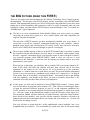
THE BIG PICTURE (READ THIS FIRST!)
There are two parts to the documentation for the Sidereal Technology Servo Control System’s
documentation. The first part is the SETUP manual, and the second part is this OPERATIONS
manual. Skim through them both to get a feel for all the topics and capabilities, but to keep from
getting lost in all the capabilities this system has to offer, we really recommend when you start
reading for content, you start with the SETUP manual, and read through it first. It’s written in a
“building block” type of approach.
The idea is to cover considerations about initially building your drive system, or perhaps
converting an existing drive system to a servo control system, and what components are
required, and what are optional.
The next part of SETUP assumes you have mechanically installed your servo motors. It
covers how to get all the “required” components hooked up to your controller: Motors,
handpad, power supply, and a serial port to a PC (and if your PC does not have a serial port,
how to use a USB-to-serial converter (dongle) to provide a serial port).
The next step, and the majority of the rest of the SETUP manual, then covers how to update
the controller with the latest firmware (to tell it that it is a controller), and to update it with
the basic “required” information about your telescope mount. It starts with how to install a
very powerful program called SERVOCONFIG, which is what you will use to send
information to the controller. It also has tools for helping you measure and set up critical
parameters for your system.
When you get to this point, you should be able to actually USE your mount without a PC.
None of the really cool bells and whistles will have been covered, and in fact basic
operations of the mount do not even need a PC to be hooked up to the controller!
(Remember, we want to learn how to walk before we run!) This section includes information
on how to use your mount in a standalone mode without a PC connected (i.e. in Drag &
Track mode, Slew & Track Mode, or Equatorial Mode). You should do this to get familiar
with this capability, even though in the future you plan to normally always have a PC
connected to be ready for those times if/when your laptop dies!
At this point, you will want to transition to this OPERATIONS manual. It starts with a
review of the basics of using the system without a PC. Then it focuses on learning the basics
of using the powerful Sitechexe program on your PC to add important capabilities like
GOTO, and how to use external programs like planetarium programs to control your mount
(i.e. click on a target in the planetarium program to aim the telescope at that target, etc.).
The Operations manual will start with how to install Sitechexe, and some related software
that it needs to have installed. And, just like with the controller, Sitechexe will need to be
updated with some basic information about your mount, and your location, etc. So, that will
be one of the first things covered.
Now you will have a mount that has a really sophisticated control capability, but a very
straightforward user interface. We recommend you spend some time at this point simply
8 of 236
USING the system out under the stars to get down using the basics before you try to also
come to grips with the more powerful capabilities the system has to offer.
When you are comfortable with operating the system using your PC and SitechEXE, then it
is time to start into the “advanced” operations. Use the OPERATIONS manual for this.
There are some advanced capabilities that make more sense than others to incorporate first,
such as using the SitechEXE tools to build a model of your mount to dramatically improve
both tracking and GOTO accuracy, and using the Periodic Error Correction capability to
eliminate periodic error in the RA drive for an equatorial mount. If you need to go back and
change any configuration information in the controller as part of using any of these advanced
capabilities, the OPERATIONS manual will give the reference to you where to go in the
SETUP manual.
There are several appendices in each of the manuals that are related to either setup activities,
or operations activities. For instances, graphics of how the components are cabled up, and
the pin outs of the various cables are in the SETUP manual. The circuit diagrams for
advanced capabilities like an optional autosync detector for the periodic error correction
routine, and a sensor for the thermal compensated focusing capability are also in the SETUP
manual appendices. The OPERATIONS manual appendices contain sections on how to
configure several of the more popular planetarium programs to interface with SitechEXE,
and on doing some really cool things like satellite tracking, and using your CCD camera to
“write” with a star’s images. There are also appendices in the OPERATIONS Manual that
contain “Cue Cards”. A Cue Card is a shorthand checklist to use out under the stars to
remind you of how to do things rather than having to try to thumb through the Ops Manual to
try to remind yourself of things.
And finally, both manuals have troubleshooting sections for when things don’t seem to go
right. Hardware does occasionally have issues (and gasp, even software!), and the Sitech
system has some powerful capabilities to help with the troubleshooting to allow working
your way through correcting things.
1 FEATURES
There are six ways to use the SiTech Controller on your telescope:
Stand alone. In this mode, the controller will track your Alt/Az telescope using the DragNTrack
or SlewNTrack modes. It will also track your Equatorial telescope or Equatorial Platform using
the Equatorial mode. Many users prefer the stand alone mode, for truly no hassle, telescope
tracking. This mode is also the most economical. It is also the mode that the SETUP Manual
will initially have you configure your system to use to allow basic operations, and to confirm
your system is wired up right and mechanically functional. This is also the logical handover
point from SETUP to OPERATIONS to learn how to use the most basic capability of the system.
Using the Argo Navis™ from Wildcard Innovations, for complete and accurate Goto and
Tracking of your telescope. This is a really cool way to go if you don't want the perceived hassle
of using a PC at the telescope. Using the SiTech unit along with the Argo Navis™ has several
advantages over other systems which use the Argo Navis™. If optional telescope encoders are
9 of 236
used, they are connected to the SiTech unit instead of the Argo Navis™ (the Argo Navis™
encoder port is un-used), and the serial port of the SiTech unit is connected to the Argo Navis™
serial port. Some of the advantages are that the encoders draw power from the more powerful
Servo Controller Batteries, so the Argo Navis batteries last much longer, and also, the fact that
the telescope simply doesn't need external encoders to work with the Argo Navis™! The user
has the option of using external encoders, or simply use the motor location instead (if you have a
system that doesn't slip), the best of both worlds!
Use the provided FREE ASCOM driver (SitechEXE.exe) from Sidereal Technology. This
requires a Laptop or Desktop PC, running Windows 98 through Windows XP. The advantage of
using the ASCOM driver, is almost any planetarium program that supports ASCOM will
accurately control your Alt/Az or Equatorial telescope. No special Virtual Serial Port drivers or
NULL modem cables to otherwise unused serial ports. This ASCOM driver is very powerful,
and supports almost every ASCOM Version 2.1 function and later. Using SiTechEXE also
provides extensive built-in capability providing periodic error correction, sky mapping for
extremely accurate pointing (PointXP), scripting and automatic sky mapping using a CCD or
DSLR camera(CalPointsXP and PlateSolveXP). This method gives the most functionality to
your SiTech system.
Use Mel Bartels SCOPE II Windows/Mac/UNIX software (Java Based), observatory quality,
incredibly accurate GOTO and Tracking http://www.bbastrodesigns.com/BBAstroDesigns.html
Mel has spent many hours providing almost every possible feature in SCOPE II. If you want
better than 1 arc minute pointing, sky to sky, or want to do serious photography, Mels SCOPE II
is an excellent tool. The ASCOM Driver is not used.
Use Mel Bartels Windows software, ScopeIII. We are excited about this, and wait with
anticipation what Mel will have put together in this new software. We understand Mel will have
this version available in late 2009
Use a Palm Pilot or Windows Mobile based PDA, a Blue Tooth Serial module and Astromist
Software by Cyrille Thieullet. We are also excited about this option, as Cyrille has created a
brilliant piece of software with many features. Please check out http://www.astromist.com for
more details. Also, soon to come is control using JavaME, which can be found on many Cell
phones!
Finally, a servo telescope control that is affordable! You can purchase a bare bones servo
controller with motors and a handpad for much less than you would imagine!
1.1 BASIC BUILT-IN STANDALONE CONTROLLER FEATURES
Directly controls two servo motors with the motor position control loops running at nearly 2000
times a second, with high speed motor encoders for position feedback on each motor.
In addition to the two encoders mounted on the motors (cleverly referred to as “Motor
Encoders”), the SiTech unit can connect to two additional high speed encoders for the telescopes
altitude and azimuth (or right ascension and declination) axes. These additional encoders are
referred to as “Scope” Encoders, or “Mount” encoders. There is no need to add an additional
"box" to connect mount encoders. Mount encoders can correct for slippage of friction drives and
10 of 236
high resolution encoders can eliminate periodic error of worm drives.
There is an Open Collector RS232 Serial port for connecting 2 or more controllers on the same
RS232 bus. The other controller axis's can be used for field de-rotators and/or focusers
(Available using PC control only).
You can connect to a wired handpad or an optional radio handpad for slewing/panning/guiding.
Signals from the wired or radio handpad work immediately, no delay as with some other
systems, because the same micro-controller that is controlling the servo motors, “listens” to the
handpad signals. No communication protocol delay. The Radio handpad protocol, is a lean and
mean protocol, taking only the time to transfer 16 bits at a quick bit rate. There is absolutely no
perceived delay between when you press a button on the handpad (radio or wired) and when the
servo motors move.
Can automatically track your telescope in “computer-less” modes like the Equatorial mode (for
Equatorial mounts), and the DragNTrack mode, or the SlewNTrack mode (for Alt/Az mounts)
without having a personal computer connected.
When running in the computer-less modes mentioned in the above paragraph, you may connect a
computer running just about any planetarium program, and the servo controller will emulate the
Tangent Digital Setting Circle protocol. This allows just about any planetarium program to
provide the “crosshair” or other indicator, of where the telescope is pointed.
Can control a dual axis tracking platform with auto stop, and then you can rewind via a handpad
command, and have dual axis tracking correction without having a personal computer connected.
Servo Motors have a FASTEST mode of operation, where if the motors can't quite keep up with
where it is supposed to be, but it is moving in the proper direction, it will not trip on position
error which is the industry standard, instead, position error is held at the point of the position
error limit. This feature makes it possible to run your motors near their limit of speed, and you
can rest assured, it will not trip on position error if your battery voltage falls a bit, or the wind
pushes against the scope.
Local search: Upon a quick combination keypad request, your telescope will search for an
object, in a circular pattern. This is the most efficient search pattern, as there is no overlap
between successive search patterns. This is a true circle, no matter where in the sky you are
looking. No inefficient ellipses at different altitudes. You have two choices of radius, reverse,
forward and pause control, and speed of the search can be changed while looking through the
eyepiece!
Internal Backlash: Backlash is internal to the controller, and instantaneously applied. Each axis
has a backlash variable associated with it, and an adjustable backlash area speed.
Equal Area Pan/Guide Speeds: The Azimuth/RA Pan and Guide speed is automatically adjusted
for different Altitude/Declinations. As you near the Zenith (or Pole), the Pan and Guide speeds
are automatically increased so the same sky area is covered in Azimuth/RA as Altitude/Dec.
This is a really cool feature, and if you experience it, you won't want to go back!!!
11 of 236
The controller has many advantages over competing systems
Small size, 2.5" by 4.25" by 1".
Power Efficient. Will last several nights on one 7 amp hour Gel Cell on most telescopes.
Built in flash memory for saving parameters.
Firmware in the controller is field upgradeable to later versions of the firmware, no need to
send it back to the factory for additional features.
1.2 ADDITIONAL FEATURES AVAILABLE USING THE FREE
SiTtechEXE PROGRAM
PointXP is a mount error modeling routine for corrections of pointing errors and is incorporated
into the SiTech.exe software. Using a PC, you can align on stars across the sky once, and then
have extremely high pointing accuracy with corrections for most mount, polar alignment, and
telescope errors on subsequent nights. Pointing accuracies of several arc seconds have been
achieved.
PlateSolveXP is a stand-alone program that determines the center of field of view of a camera
and passes those coordinates to PointXP for exceptional pointing capability with the mount It
graphically shows the extracted stars, the catalog stars and the matched stars. It also displays the
J2000 coordinates of the cursor, a useful feature for astronomical research and object
identification.
CalPoints is a utility that works with SiTechEXE to help automate the mapping of the sky using
PlateSolve and PointXP to generate a sky database of mount corrections for extremely accurate
mount pointing.
Built-in periodic error correction and support for PemPro™ operation is available in SiTech.exe
with a PC connected. You can record periodic error directly in SiTech, or use PemPro™ to
determine the correction pattern. The controller will then apply the corrections automatically.
This feature requires either manually synchronizing the worm gear rotation or using an
AutoPECSynch sensor on the worm gear. Circuits for these sensors are shown in the appendix
in the SETUP Manual.
Use high resolution encoders on the mount (Automatic Interpolation Error Correction for sub
arc-second tracking using 320,000 tick or 500,000 tick Gurley encoders is also provided). When
used on an Equatorial mount, periodic error in tracking is virtually eliminated using these high
resolution encoders. When used with Alt-Az mounts, slippage and periodic error in the drive
trains are virtually eliminated.
Park and UnPark can be used to retain sky alignment from session to session. A repeatable park
position alignment, either by optically sighting on a target or using a precision level on a GEM
balance shaft and scope and accurate time on a PC can allow immediate slewing to targets after
startup.
Scripting can be used to plan and run a night’s observing session, or even run the mount
remotely. Using a PC, SiTech.exe has a script building application you can use to make and run
12 of 236
the script.
Polar Alignment of an equatorial mount can be quickly accomplished with the PC application
built-in to SiTech.exe.
Built-in Simulator capability of SiTech.exe automatically senses if there are no servos connected
and operates with the message: “Faking Servos” in the message window. This powerful feature
allows you to learn and test the controller system along with Ascom connections to other
software such as TheSky™, Earth Centered Universe, Cartes Du Ciel, Maxim, Pempro™, Elbrus
and many other programs.
Built-in database capability with alignment stars and Deep Sky Objects (Messier, NGC, IC) for
synch or GoTo slewing.
Customization of the display of SiTech.exe controls on a PC allows you to set the colors of
buttons and displays to suit your taste.
Windows Configuration program is supplied free with the unit or is available online for free
downloading.
Very active user community with an e-mail list-server and a user community Website
http://www.sitechservo.info/
1.3 COMPARISON BETWEEN STEPPER SYSTEM AND SERVO
SYSTEM
A servo system has many advantages over a stepper system:
Wider dynamic range. This means a servo system will track your telescope nearly perfectly
and still obtain faster slew speeds than a comparably geared stepper system.
Angular accuracy of the motor while tracking is much better. There are many errors in a
stepper system when being micro stepped. Generally speaking, the micro steps are not nearly as
accurate as the resolution of the micro step. There are many errors such as mechanical winding
differences, magnetic hysteresis, torque error, and several others that can be partially
compensated for in software with a stepper system, but never will be as good as a servo system,
which will almost all the time be within 1 encoder tick of it's desired location at all times (while
tracking).
More torque. Small servo motors will control telescopes as large as 41 inches!
Much lower current during tracking. Batteries will last much longer.
No resonant frequency's to battle.
Motors will never “miss” steps. Many times stepper motors will simply stop instead of turning
during slewing. The computer controlling the stepper motors will lose its position information
when this happens.
13 of 236
A real time operating system is in the Servo Controller itself, thus making a real time
operating system unnecessary for the controlling computer (some stepper systems have this too).
This means the same computer can operate your telescope with a planetarium software interface
while still tracking, perform imaging, autoguiding the telescope, controlling a dome, etc, all at
the same time using the same computer. This can be a significant cost savings of a servo system
over a stepper system, evening the cost savings of a stepper over a servo system.
Much smaller size (in the case of the SiTech controller anyway).
If only simple tracking is desired, no external computer is necessary (SiTech feature).
If no external computer is desired, but GoTo's are, the SiTech Controller can be controlled by an
Argo Navis™ a Palm computer, a Windows Mobile PDA, or a Sky Commander.
The stepper system has only one advantage over the servo system that we can think of: Cost,
although a servo system can be less than four or five hundred dollars, including controller, using
surplus motors, and software if you do most of the work yourself. Although cost is an advantage
of the Mel Bartels DOS based Stepper system, Mel’s system is the only stepper system we know
of that is less than the SiTech servo system, and then if you want to do imaging, planetarium
software control (while still tracking) or other simultaneous computer operations, you'll still have
to use a 2nd computer.
Some books or articles may mention Servo Lag as an advantage of a stepper system over a servo
system. This isn't an advantage when compared with the SiTech Servo system. When tracking,
the servo motors will almost all the time be within ONE motor encoder tick and occasionally,
two motor encoder ticks of its desired position. This is usually between 1/10th to 1/4 of an arc
second (depending on your gear ratio).
Despite the many advantages of a servo system over a stepper system, many successful stepper
systems have been created, which work extremely well.
1.4 SAFETY
The servo motors are powerful motors that can do extreme damage to equipment, and/or plant
and animal life. Please be careful that your telescope doesn't move to a mechanical limit (such as
the ground). You may damage the motors or gears, and you may injure yourself or others. Use
this product at your own risk.
1.5 SOFTWARE VERSIONS
The manuals are written and illustrated with screen shots using current versions of SiTech
control software (SiTech.EXE v054M) and Firmware Version 35C. Please update to these or
later versions in order to use all the features available. You can find the latest versions at
http://www.sitechservo.info/downloads
14 of 236
2 OPERATION WITHOUT A PC
The Sitech system is capable of running without any external control system connected to the
controller (aka in computer-less mode). There are four different modes available to do this:
1. Drag and Track (which assumes you DO have mount encoders on the mount, which can
be an Alt/Az or an Equatorial mount). With mount encoders, you have the option to
simply loosen the clutches on the mount, and grab the telescope and “drag” it to another
location, and retighten the clutches. The mount encoders will update the controller’s
knowledge of its position, and tracking will resume at the proper rate for the new location
(obviously for an equatorial mount the rate stays the same).
2. Slew and Track (which assumes you do NOT have mount encoders on the mount, which
can be an Alt/Az or an Equatorial mount). For this mode, the system relies on the motor
encoders for slews to know where the mount is aimed. So you need to use the handpad to
slew to a new location to have the tracking rates be correct (again, for equatorial mounts,
the rates will obviously not change)
3. Equatorial Mode, which assumes you have an Equatorial mount (or a tracking platform)
that is reasonably polar aligned, and works with or without encoders, since basically all it
does is turn the RA axis at a sidereal rate.
4. Operation with an Argo Navis™ Digital Telescope Computer. It is possible to use the
Sidereal Technology Servo Controller in a GoTo and Tracking mode using an Argo
Navis™ Digital Telescope Computer. The Argo Navis™ needs to have version 1.1.6 or
later installed in its firmware. You can download and upgrade either or both units by
visiting the appropriate website. The telescope encoder information comes from the
Sidereal Technology Servo Controller instead of the encoders themselves. There is only
one cable connected to the Argo Navis™, and it is the Serial Cable. See Appendix E in
the SETUP Manual for the cable diagram. If you don't have telescope encoders, not to
worry, because you can select the SlewNTrack mode of operation, and now the encoder
information will come from the servo motors, not the telescope encoders. Also, if you do
use telescope encoders, they will be powered from the Servo Controller power, thus the
Argo Navis™ batteries will last much longer.
The first three modes do not provide GOTO capability, but do provide basic capabilities like
PEC (if programmed into the controller), and simple tracking operations, which make them ideal
for portable systems to simply plop them down and be able to use them. Initializations are done
using the handpad.
2.1 ALT-AZ DRAG AND TRACK MODE
The DragNTrack mode is used primarily with Alt-Az mounts if you would like to push your
telescope by hand, or slew with the handpad, but don't need super-accurate tracking or GoTo
capabilities, but would like computer less accurate tracking. The DragNTrack or SlewNTrack
mode may be a nice feature to use. If you have a telescope of aperture 16 inches or more, it may
be more cost effective than a tracking platform, and there are many other advantages to use the
15 of 236
dual servo controller and the Drag and Track mode instead of a tracking platform.
To use the drag and track mode, your Alt/Az telescope must have the following hardware (in
addition to the servo controller):
1. A pair of servo motors to drive the telescope in altitude and azimuth.
2. Clutches on both altitude and azimuth connected between the motors and the telescope, so you
can "drag" the telescope anywhere in the sky, without damaging the servo motors. (Note: you
can use the DragNTrack mode, even if you have no clutches, but do have telescope encoders.
You will have the disadvantage of only slewing with the handpad, instead of pushing the
telescope by hand).
3. A pair of encoders mounted to your telescopes' altitude and azimuth axis's.
4. A handpad.
5. A 12 -24 volt power supply.
A computer is not required for operation, only to configure your servo controller.
2.1.1 Setting Up the Drag and Track Mode
For the drag and track mode to work properly, the controller must "know" several things.
1. The number of motor encoder ticks for a complete revolution of the telescope in both the
altitude and the azimuth.
2. The number of telescope encoder ticks for a complete revolution of the telescope in both the
altitude and the azimuth.
3. How fast the slew setting should be.
4. How fast the pan speed should be.
5. (Optional) Latitude of the observing session.
For details on how to set up your system to use Drag and Track mode, refer to the SETUP
Manual, in the AUTO TRACKING TAB Dialogue section.
When you calculate the encoder ticks, it's important to understand the resolution of your
encoders. Generally speaking, the effective number of ticks is 4 times the resolution of the
encoder. This document uses the effective encoder ticks unless otherwise stated. If your
encoders have 2048 as part of the part number, the encoder wheel has 2,048 lines on it. The
effective encoder ticks will be 4 times this, or 8,192.
Using the ServoConfig software, and the “Edit Parameters” button, be sure all of the motor and
encoder ticks per revolution are set properly (in effective encoder ticks). Also, be sure that the
Right button on the handpad moves the scope clockwise (looking down), and the Up button on
the handpad moves the telescope up. If not, change them using the features of ServoConfig.
Now select the “Auto Tracking” tab. Now click on the “DragNTrack” radio button.
It would be good, but not absolutely necessary to enter the latitude of your observing site, which
is also on the “Auto Tracking” tab.
For the DragNTrack to work properly, it's important to note that the UP handpad key needs to
move the telescope up in altitude, and the RIGHT key needs move the telescope azimuth in a
clockwise direction. It would be easy to put a negative number into the slew and pan rates to
16 of 236
obtain these results, and the controller would respond with the opposite direction, but the
trigonometry would still be wrong.
It's also important to note that when the telescope is moving clockwise, the azimuth telescope
encoder should be increasing, and when the telescope is moving up, the altitude telescope
encoder should be increasing. If these move backwards, then the direction needs to be changed
using the ServoConfig software, or change the wiring of the encoders.
Note: If using an old BBAstroDesign handpad (the kind with a switch in the middle instead of a
push button) and Servo firmware version 1.5 or earlier, the slew and pan speeds MUST be a
negative number, but the direction of motion must still be the same as listed above (unless using
servo version 1.6). You really should upgrade to the latest version (V3.5C or later).
2.1.2 Operation of Drag and Track Mode
If you want the scope to start tracking without initialization, point the telescope at the celestial
pole, and then turn the power on the controller. At this point, if you've already set up and saved
your latitude, the system will be initialized. It will immediately start tracking. No further
initialization is required (while pointing at the celestial pole, the scope won't appear to track
because the celestial pole doesn't move!).
If your latitude isn't set up and saved to flash ROM, you will have to initialize at the scope zenith
and the celestial pole. To initialize the Altitude, move the scope (by hand or with the handpad)
up to the scope zenith. It could be convenient to have a mechanical stop mounted on your scope,
so it is easy to find this location. Press and hold the top right (RTN) key for more than 4
seconds. At this point, the controller adjusts your altitude so it reads 90 deg's. (Important Note:
there was a bug in the controller flash ROM in versions 1.5 and earlier, and this number was
calculated wrong. If you have firmware version 1.5 or earlier, please upgrade to version 1.6 (or
later) or enter the latitude using ServoConfig).
To initialize the azimuth, move the scope to the celestial pole. Now press and hold the top left
key (ESC) for more than 4 seconds. At this point, the controller initializes the azimuth, and if
you haven't initialized the altitude, it initializes the altitude to your saved latitude, otherwise it
initializes the latitude.
If you have initialized both the altitude and azimuth, you may save the new latitude value by
pressing and holding both top keys for more than 10 seconds. This saves the latitude to the flash
ROM, so next time you can simply initialize the scope on the celestial pole, and press the left
hand key for more than 4 seconds.
To perform photography, or for very fine centering, it may be desirable to enter the guide mode.
This is done by holding down the top right key, then pressing the right key. Now the speed
changes by adding or subtracting the guide rate from the current tracking rates. To revert back to
the normal mode, hold down the top right key, and press the right key again. This feature doesn't
work with the old BBAstroDesign handpads with a center switch. If you are using servo version
1.6 and you have a radio handpad receiver, you will toggle through slew/pan/guide modes using
the SPD button.
17 of 236
You may slew the telescope with the handpad, or move the telescope by hand, and when done
slewing or moving, the telescope will immediately start tracking again, at the new drive rates
based on the telescopes altitude, azimuth and the latitude. To stop tracking, press the top right
key. To start tracking again, press it again. When the tracking is stopped, the LED's will blink
off briefly every few seconds (version 1.6 of firmware and later).
2.1.3 Review of Alt-Az Initialization options
It may be confusing, because there are several ways to initialize the telescope. The user has
three choices.
Choice 1:
Step 1. Before turning on power to the controller, position the telescope to the celestial pole
(NOT Polaris if in the northern hemisphere, but the pole itself!). Turn on power.
The controller initializes the azimuth, and initializes the altitude to the same value as the last
saved latitude. Using Choice 1 means you don't even have to use the hand paddle, although you
must have previously saved your latitude.
Choice 2: To initialize if your scope latitude is not programmed into the Servo Controller, point
the telescope at the scope zenith, then press and hold the top right key for more than 5 seconds
(when the LED on the controller flashes fast, you may let up). Now, point the scope at the
Celestial Pole. Now press and hold the Top Left key for more than 5 seconds (when the LED on
the controller flashes fast, you may let up). Your scope is now initialized, and the DragNTrack
or SlewNTrack will be working (assuming the Servo controller is properly configured).
Scope latitude is the effective latitude of your scope. It is the same as your own latitude if your
scope is level, but will be a slightly different latitude if the scope is not level in a north/south
direction. This process will calculate your latitude. If you want to save this automatically
calculated latitude in the Servo Controllers' Flash ROM, simply press and hold both the top right
(RTN) key and the top left (ESC) key simultaneously for more than 10 seconds.
Note: The latitude calculation was wrong on the SiTech Controller Firmware versions 1.5 and
earlier. If you have version 1.5 or earlier, you will have to enter the latitude using the
ServoConfig software, or upgrade to version 1.6 or later.
Choice 3: If your scope latitude is known, and it is programmed in the Sidereal Technology Dual
Servo Controller, simply point the scope at the Celestial pole, now press and hold the Top Left
(ESC) key for more than 5 seconds (when the LED on the Servo Controller flashes fast, you may
let up).
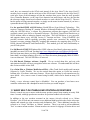
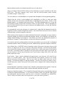
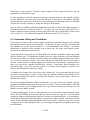
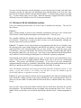
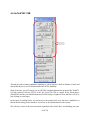
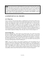
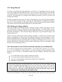
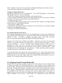
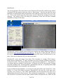
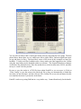
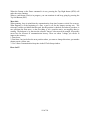
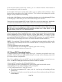
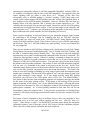
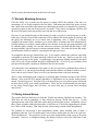
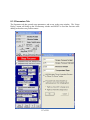
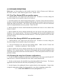
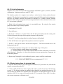
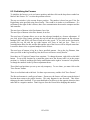
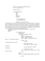
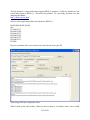
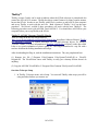
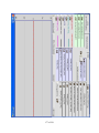
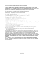
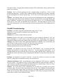
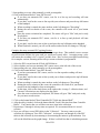
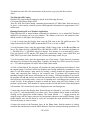
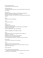
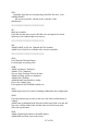
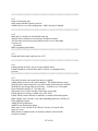
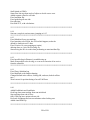
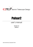
Here are some screen shots from Earth Centered Universe which show placement for celestial
pole alignment. The QuickFinder has the two middle circles but not the outer circle. The two
middle circles are the same size in both the QuickFinder and the Telrad. Limiting magnitude is
6.0.
18 of 236
19 of 236
While the controller is in the DragNTrack mode, the serial port can be connected to a laptop
running almost any planetarium software. Set your software to connect to a "Tangent" encoder
interface box, and you will be able to surf the sky using the planetarium software! When setting
up your planetarium software, set up both encoder resolutions to 18000. Also, do not use the
option that your telescope is on a tracking platform. Think of it like a telescope without a
platform where you have this little guy pushing it all the time, exactly keeping up with the stars.
That's what your planetarium program will "think"!
Also, set the baud rate of your planetarium software to 19200, no parity, 8 data bits, and 1 stop
bit. If your software doesn't support 19200 baud rate, contact us, there is a way to set the
controller to 9600 baud if you have firmware version 1.5 or later.
It's a good idea to set up the DragNTrack mode even if controlling with a computer or the Argo
Navis™. When connected to a computer or Argo Navis™, the controller automatically leaves
the DragNTrack, SlewNTrack or Equatorial modes, but it doesn't save the mode to the flash
ROM. If you do this, you will have tracking (if initialized on the celestial pole) even before you
connect the Argo Navis™ or the computer.
If tracking before connecting a computer or Argo Navis™ is not desired, there is no need to
initialize the controller on the celestial pole.
2.2 ALT-AZ SLEW AND TRACK MODE
This mode is similar to the drag and track mode, but is used if you don't have shaft encoders on
the altitude and azimuth of the telescope.
To use the Slew and Track mode, your Alt/Az telescope must have the following features:
1. A pair of servo motors to drive the telescope in altitude and azimuth.
2. A handpad.
3. A 12 -24 volt power supply.
This mode uses the servo motor encoders as the telescope position. You must use the handpad to
slew the telescope. You must select the SlewNTrack mode from the “Auto Tracking” tab of the
“Edit Parameters” of the ServoConfig software.
You must also set up the number of telescope encoder ticks to be the same number as the number
of motor encoder ticks using the ServoConfig software. This is done automatically for you if
you use the ServoConfig software, and you click on SlewNTrack mode.
Important Note: If your telescope has encoders for altitude and azimuth, but doesn't have
clutches, your best bet would be to use the DragNTrack mode, but slew with the handpad instead
of “dragging” the scope.
If you don't have external encoders, and you plan to use the SlewNTrack mode, you must set
your controller up for SlewNTrack so the controller will ignore the telescope encoders if using
the Argo Navis™. If tracking before connecting a computer or Argo Navis™ is not desired,
there is no need to initialize the controller on the celestial pole.
20 of 236
2.3 EQUATORIAL MODE
The Equatorial mode is provided for equatorial platforms, or equatorial mounts, both Fork and
German Equatorial Mounts. The configuration options allow the Right Ascension motor to start
tracking when powered up, at the rate specified. This allows operation of the mount without a
PC connected. However there are many features that require a PC in order to achieve the
maximum utility of the system. With a PC, the SiTech can Park and UnPark, use PointXP to
provide extremely accurate pointing for GoTo operation, PEC error correction and (with a high
resolution mount encoder on RA) using Tick Management (TM) the mount can be free of PEC
and achieve sub arc-second tracking.
2.3.1 Setting Up the Equatorial Mode
Using the ServoConfig software, click on “Edit Parameters”, then “Auto Tracking”. Click on the
Equatorial mode radio button. Set up the Equatorial rate. If you know the number of motor
encoder ticks for one revolution (360°, don’t add sidereal) of the Right Ascension axis, enter that
number on the green text box to the right. After pressing the Enter key, the proper Equatorial
rate will be calculated and will appear in the “equatorial rate” text box (this rate will account for
Sidereal).
You need to set the direction of tracking fofr operation in either the Northern or Southern
hemisphere. The way to set this is to point the scope toward the west and observe the direction
of motion when the handpad buttons are pushed. Pushing the West button (on the right) should
make the scope move down, toward the horizon. Pushing the UP button should make the scope
move toward the pole (North or South depending on the hemisphere. If the movement is not as
described, you will need the reverse the servo direction using ServoConfig software.
You can adjust the tracking rate up and down by pressing a certain sequence on the handpad.
The amount it is adjusted per handpad press is in the text box labeled “Equatorial Up/Down
Adjust”.
If you have a platform, set the “Tracking Platform Goal” to the number of motor encoder ticks
where you want the platform to stop. The SiTech controller will stop at this point, and then you
can then perform a re-wind.
If you have an equatorial telescope, set this platform goal to over 10,000,000. This will make it
impossible to stop at the platform goal; it will continually track forever (if you don't stop it).
If the motor tracks the wrong way, you can put a negative number in the “Tracking Platform
Goal”.
2.3.2 Operation of the Equatorial or Tracking Platform Mode
If using an equatorial platform, before powering up the controller, be sure the platform is fully
rewound. This will be its home position.
Upon power up, or after a rewind, the Right Ascension motor will turn at the configured speed,
until it reaches the configured goal. To rewind, press both top switches. This is possible at
21 of 236
anytime. The servo motor will return to the same location it was when power was turned on; at
its programmed slew speed rate.
To Cancel rewind, press any direction key.
If using an equatorial telescope, the above paragraph will not be applicable, as the platform goal
will be set for 10,000,000 or greater.
To stop tracking, press the top right key. To start tracking again, press it again, or press any of
the direction keys. When the tracking is stopped, both LED's will blink off briefly every few
seconds (version 1.6 of firmware and later).
Only the new handpad will allow fine tuning the tracking speed. To raise the tracking speed,
press the top left key, and while holding it down (think of it as an ALT key) press the up
direction. To lower the tracking speed, press the top left key, and while holding it down (think of
it as an ALT key) press the down direction.
The up/down adjustment will not work if you have set up the local search feature (version 1.7 or
later of the firmware). To enable the UP/Down adjustments, you will have to enter a value of
zero in the local search distance and speed parameters.
To perform photography, it may be necessary to enter the guide mode. This is done by holding
down the top right key, then pressing the right key. Now the speed changes by adding or
subtracting the guide rate from the current rates. To revert back to the normal mode, hold down
the top right key, and press the right key again. This feature only works with the new handpad.
This will be un-necessary if you are using a radio handpad receiver, as in this case, the SPD
switch on the transmitter will toggle between Slew/Pan/Guide modes. If you are using an auto
guider, as soon as the guider commands are sent to the controller, the SiTech is automatically set
for guide speeds.
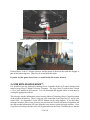
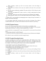
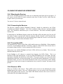
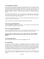
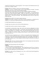
2.3.3 Observing the Crab Pulsar
Here is a Challenging Idea. If you have or have access to, a very large aperture telescope, 28
inches or larger, you may be able to see the crab pulsar blink. Here's how. Obtain a servo motor
with encoder that is able to run at least 1,800 RPM, you could connect this motor to a servo
controller, and put an interrupter on the shaft of the motor (a circle with a pie shape cut out of it),
balance the interrupter, and hold this assembly between the secondary mirror and the eyepiece,
while running at somewhat less than 1800 RPM. You may be able to see the pulsar wink in and
out! To test this out, you may use one of the LED's. It winks at the same frequency of the crab
pulsar while in the equatorial mode! You can configure the equatorial mode to automatically run
this motor at the proper speed.
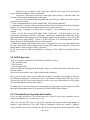
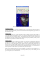
Dan Gray reports that he tried this, and succeeded!!! His report follows:
“A group of about 8 of us were able to SEE the pulsar fade in and out using this approach! We
were using the 61 inch Kuiper telescope near Tucson Arizona, so I dusted off my pulsar detector
and took it along. It was fairly easy to see the pulsar in the 61", without using anything at all, but
when the chopper was in, it was harder to detect. Even with the 61", it was challenging, but
everyone that tried, was able to see it.”
22 of 236
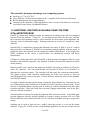
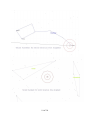
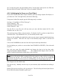
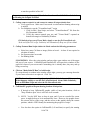
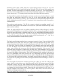
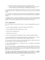
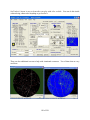
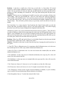
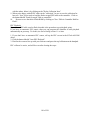
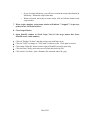
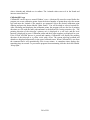
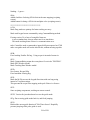
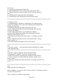
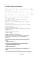
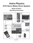
Picture above is the “chopper” mounted to the 61” Kuiper Telescope
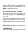
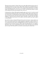
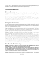
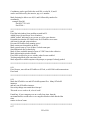
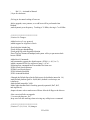
Pictured above is the 61” Kupier telescope and the group of observers that used the chopper as
part of their observing time. (Dan Gray is second from the right).
If you do try this, please let us know, we would really like to hear about it!
2.4 USE WITH AN ARGO NAVIS™:
It is possible to use the Sidereal Technology Servo Controller in the GoTo and Tracking mode
using an Argo Navis™ Digital Telescope Computer. The Argo Navis™ needs to have version
1.1.6 or later installed in its firmware. You can download and upgrade either or both units by
visiting the appropriate website.
The telescope encoder information comes from the Sidereal Technology Servo Controller instead
of the encoders themselves. There is only one cable connected to the Argo Navis™, and it is the
Serial Cable. See Appendix E in the SETUP Manual for the cable diagram. If you don't have
telescope encoders, not to worry, because you can select the SlewNTrack mode of operation, and
now the encoder information will come from the servo motors, not the telescope encoders. Also,
if you do use telescope encoders, they will be powered from the Servo Controller power, thus the
23 of 236
Argo Navis™ batteries will last much longer.
2.4.1 Setting up the Argo Navis™:
Several items need to be set up on the Argo Navis™ before operation. Go to the Setup menu,
then select the Serial Port then Serial 1. Make the Startup command be SiTech. Also, set the
baud rate to 19200.
Go to Setup and find the Altitude and Azimuth encoder resolutions. Change these to +18000.
Set up other parameters as required for your telescope, such as location, etc. Be sure to read the
Argo Navis™ manual. Note, the encoder resolution parameters in the Argo Navis™ do need to
be set for +18000, regardless of the actual encoder resolution. This is extremely important. The
Servo Controller always scales the encoder ticks for 18000, even if you have other resolution
encoders.
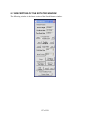
2.4.2 Setting Up the SiTech Controller for Argo Navis™:
Now you need to set up some things in the Sidereal Technology Servo Controller. Using the
ServoConfig software, click on the “Edit Parameters” button, then on the “Misc and Action” tab.
You must have version 1.0 or later of the ServoConfig software. Check the box labeled “Use
Argo Navis™”
If you don't have telescope encoders, set the Sidereal Technology Servo Controller in the
“SlewNTrack” mode. If you do have telescope encoders, put the Sidereal Technology Servo
Controller in the “DragNTrack” mode. Please read the section on DragNTrack and SlewNTrack
for setting in this mode. Be sure all of the parameters are set properly for proper SlewNTrack or
DragNTrack operation. Be sure the telescope tracks reasonably accurately in the auto track
mode.
Setting your SiTech to be in the DragNTrack or SlewNTrack modes has several advantages. In
addition to proving that all the telescope encoder resolutions and directions are programmed
properly, it has the advantage that if you want to simply track without the Argo Navis™ on a
particular evening, you can initialize on the Celestial Pole, and then you can have tracking
without the Argo Navis™, or if you connect the Argo Navis™, you can have more accurate
tracking and also GOTO's.
Important: If you don't have external encoders, you MUST select the “Ignore Encoders” option,
so the controller will ignore the external encoders.
2.4.3 Operation of the Argo Navis™:
OK, now connect the Sidereal Technology Servo Controller to the Argo Navis™ using a serial
cable fabricated as shown in appendix E of the SETUP Manual. As soon as you press both top
buttons on the handpad (ESC and RTN) at the same time, the communication with the Argo
Navis™ will begin, and the DragNTrack or SlewNTrack modes will be disabled. To check that
the communication is working properly, go to the Encoder menu item in the Argo Navis™, and
make sure the angles change with telescope movement.
24 of 236
You are now ready to initialize the Argo Navis™. Please follow instructions in the Argo
Navis™ manual for initializing the Argo Navis™.
Now the telescope should start tracking properly when the Argo Navis™ is initialized. For
GOTO's, simply select an object using the Argo Navis™, then after confirming that the object is
above the horizon, press the handpad ESC and RTN buttons at the same time (Top Left and Top
Right buttons). The scope should now move to the object.
To stop a slew, press any direction key on the handpad. To restart the slew, press the ESC and
RTN (Top Left and Top Right) buttons again.
To stop tracking, press the top right key. To start tracking again, press it again. When the
tracking is stopped, the LED's will blink off briefly every few seconds (version 1.6 of firmware
and later).
Some useful info about the Argo Navis™ mode. The SiTech controller does two slews each
time you slew to another object. The first slew gets it in the area, then the final slew takes it to
the exact position. The reason it does this, is because on long slews, the earth will turn, and thus
the location will have changed after the 1st long slew.
2.5 USE WITH SKY COMMANDER™
It is possible to connect the SiTech controller to a Sky Commander™ XP4 computer for GOTO
functionality without being connected to a PC. If you want to use Sky Commander™ with a
SiTech controlled mount you will need to have Sky Commander™ XP4 with version 5.02 of SC
software. Your SiTech should have firmware version 3.3C.BIN or later.
The telescope encoder information comes from the Sidereal Technology Servo Controller instead
of the encoders themselves. There is only one cable connected to the Sky Commander™, and it
is the Serial Cable. See Appendix E in the SETUP Manual for the cable diagram. If you don't
have telescope encoders, not to worry, because you can select the SlewNTrack mode of
operation, and now the encoder information will come from the servo motors, not the telescope
encoders. Also, if you do use telescope encoders, they will be powered from the Servo
Controller power, thus the Sky Commander™ batteries will last much longer.
2.5.1 Set Up SiTech Serial Port
The SiTech controller RS-232 port is used for both connecting to a PC for setup with
ServoConfig as well as later connecting to the Sky Commander™. You need to set both the Sky
Commander and SiTech Controller to the same 9600 baud rate. The easiest way to set the baud
rate for SiTech is to use the "Terminal Window" in ServoConfig. You can issue commands like
this without doing anything else: type SB1 where: SB# = Set Baud Rate (1 = 9600, 2 = 19200).
When you connect the Sky Commander™ RS-232 Serial Communications cable to SiTech, you
need to disconnect the PC cable from the SiTech RS-232 port and . It is a good idea to have both
the SiTech controller and the Sky Commander™ turned off when connecting and disconnecting
the RS-232 cables. The cable diagram to connect the two units is shown in Appendix E in the
SETUP Manual.
25 of 236
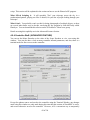
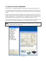
2.5.2 Setting up SiTech for Sky Commander™
This section addresses only the ServoConfig settings specific to using the Sky Commander™
with the SiTech controller.
First connect your SiTech controller to your PC via the supplied DB-9 to RS-232 cable. Launch
the ServoConfig.exe program. Press the "Edit Parameters" button on the left panel. When
prompted, you will likely want to get the settings from the SiTech controller or possibly a
configuration file if you have created one earlier. At this point, it is assumed that you have
already configured your controller with motor and encoder info and confirmed that the SiTech
servo motors and encoders move in the proper directions using the hand pad buttons. Follow the
instructions in Section 2.1.1 Setting Up the Drag and Track Mode for Alt-Az mounts. Follow
the instructions in Section 4.13 EQUATORIAL AND GEM INVERT BUTTON SETUP
for GEM and Equatorial mounts.
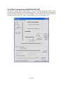
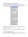
Setting Up SiTech for Sky Commander with Alt-Az Mounts
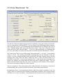
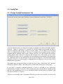
The"Configuring Sidereal Technology Servo Controller" window has 3 tabs: "Motors/Encoders",
"Auto Tracking" and "Misc. and Action". Select the 2nd tab (Auto Tracking). In this panel,
select the "Use DragNTrack Mode" checkbox. Next select the 3rd tab (Misc. and Tracking). In
this panel, select the "Enable Sky Commander™ checkbox. Be sure to save these settings to the
controller by pressing the "Send Configuration to Controller". Additionally, since the controller
will be turned on and off for most scenarios, press the "Save Controller Configuration to Flash
ROM" button so that the settings remain in effect when turning the controller off and on again.
It is also recommended that these settings be written to a file for retrieval later should the settings
need to be recovered later. Press the "Save This Configuration to File" to create the .car file.
This completes the SiTech controller setup. Note that it may be necessary to fine tune the
SiTech controller later but these settings above are required for use with Sky Commander™.
The physical connections to the SiTech controller are the power, motor and motor encoder wires
as well as the mount encoder cables. See the Appendix F in the Setup Manual for instructions
on how to connect encoders to the SiTech controller.
The connection between the SiTech controller and Sky Commander™ is the RS-232 Serial
Communications cable provided with the Sky Commander™. The RJ-22 plugs into the SiTech
Controller and the RJ-11 plugs into the Sky Commander™. Be sure to plug the RJ-11 into the
smaller port on the Sky Commander™, it will plug into either one but will only work with the
smaller RJ-11 port. Placing a piece of electrical tape over the RS-232 port on the Sky
Commander™ will prevent inadvertently using the wrong port.
2.5.3 Setup Sky Commander™ for use with SiTech Controller
The XP4 version of the Sky Commander™ is required for use with SiTech systems. At the time
of the writing of this document, firmware 5.0.2 is the current version and is used to prepare these
setup instructions. Earlier versions that have firmware 3.38 and lower are not supported.
26 of 236
Using the Sky Commander™ to perform GOTO operations with your telescope is easy but there
are a few specific steps that need to be taken to get it working well. The following procedures
were contributed by Randy Pufahl (thanks Randy).
To set up the Sky Commander™ for use with SiTech it is necessary to program the flash
memory (settings that remain in effect from session to session) with information such as the
communication baud rate, encoder info and of course whether it is to work with the Sitech
controller. There is a special startup procedure to put the Sky Commander™ into this mode
where these values can be viewed, entered and saved. While pressing the up and down arrows,
turn the Sky Commander™ on. Below is the configuration startup procedure that allows
changing the settings. After the settings are entered and saved, they remain in effect until
changed from within this mode, even if the Sky Commander™ is powered off or had the battery
removed.
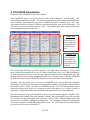
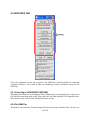
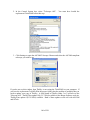
Once the unit is in configuration mode, there are 11 settings that can be changed. The first,
parameter lets you choose between 4 different setups, presumably for using the Sky
Commander™ with 4 different scopes. Select the desired configuration number and hit enter.
There will be a confirmation message that this has been saved to EPROM so it will take effect
the unit is turned back on. I believe that you need to press enter after changing each value for the
values to take affect when the unit is turned back on.
1) Select Setup
1) [1] [2] [3] [4]
Press the down arrow to get to the next (and all subsequent) configurable items. Note the current
setting is capitalized (sometimes completely, sometimes just first letter).
2) Scope Mount?
2) <- fork DOB germn ->
3) Set Hemisphere
3) North south
This parameter is scope/installation dependent. I do not think this is used when the encoder info
comes from SiTech controller over the RS-232 cable (encoders connected to SiTech controller).
If you confirmed the SiTech direction of encoders and motion as earlier directed then set this to
NORM.
4) RA Direction
4) NORM rev
This parameter is scope/installation dependent. I do not think this is used when the encoder info
comes from SiTech controller over the RS-232 cable (encoders connected to SiTech controller).
If you confirmed the SiTech direction of encoders and motion as earlier directed then set this to
NORM.
5) Dec Direction
5) NORM rev
RA Encoder resolution MUST be set to 18000 and the encoders attached to the SiTech
controller.
27 of 236
6) RA Encoder Res.
6) 18000
RA Encoder resolution MUST be set to 18000 and the encoders attached to the SiTech
controller.
7) Dec Encoder Res.
7) 18000
8) FastTrk ON/OFF
8) OFF 12v on
Set to ON. If the telescope is a DOB on top of an equatorial table the clock needs to be turned
off.
9) Sidereal Clock
9) ON off
RS-232 baud rate must be set to 9600 when attached to the Sitech controller. Note that the
default SiTech baud rate is 19200, so it also needs to be changed to 9600.
10) RS-232 Baud Rate
10) <- 9600 ->
Set the SiTech mode to ON.
11) SiTech Mode
11) Off ON
Press enter to save the last value of "ON" if it was just changed.
Turn Sky Commander™ off.
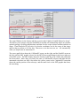
2.5.4 Initial Setup and Testing of Alt-Az Sky Commander™ with SiTech
For new installations and for times when one wants to verify that the encoders are functioning
properly, it is best to do it before proceeding further. With the scope pointing at the celestial
pole, turn the Sitech controller off and then on. Turn the Sky Commander™ on and enter the
current date. Press enter to Sight 1st Star (Polaris). Press enter again to Sight 2nd Star (Polaris).
The display should now look something like this;
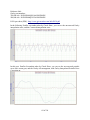
02h 38m +89.3
APN_0001 <> CEP
Press the up arrow on the Sky Commander™ to display the count down encoder info. The top
line of the display should look something like this:
* <-2.7 ^-20.2°
This means that APN_0001 in Cepheus is 2.7 degrees (east) and 20.2 degrees up from the scopes
current location.
First test the azimuth encoder for direction by pressing the left directional button on the SiTech
hand pad. Move the scope about 10 degrees (toward the north west) with the left button.. The
28 of 236
display should look something like this:
->352.7 ^-20.2
If your azimuth encoder is setup correctly, it will show that the scope needs to move back east
7.3 degrees (360 - 352.7 = 7.3). Since the scope started 2.7 degrees from the target and we
moved the scope 10 degrees in that direction, it overshot the target by 7.3 degrees. This is
correct. If the azimuth display on the Sky Commander™ did not change, see the trouble
shooting section below. If the azimuth number incremented from 2.7 to 12.7 (roughly), then the
encoder direction is probably reversed in the Sky Commander™ (see setup above).
Next test the altitude encoder setup. Press the up arrow on the SiTech controller. Move the
scope up about 10 degrees. The display should look something like this:
-> 352.7 ^-10.2°.
This shows that we moved 10 degrees toward our target (still APN_0001). If the altitude
encoder value changed from ^-20.2 to ^-30.2°, then the encoder direction is reversed in Sky
Commander™.
Once the encoder direction is correct, the system should be ready for use. Note that proper
pointing requires the correct encoder tick values setup in the SiTech controller as well as a
reasonably accurate mount.
2.5.5 Starting and Using SiTech with Sky Commander for Alt-Az Ops
Starting with both units off, first turn on the SiTech controller and slew to the North Star /
celestial pole. Turn SiTech controller off and then back on. This is where the scope assumes
that it is starting, pointing at the celestial pole. This is done so that subsequent tracking while
setting up the Sky Commander™ is reasonable.
Next turn on the Sky Commander™. Enter the correct date. Perform the 2 star init with Sky
Commander™ (See Sky Commander™ user manual for init procedures). It is not recommended
using Polaris for the sight stars in Sky Commander™. Select 2 start at least 20 degrees from the
celestial pole. The 2 stars should be in the general area where the scope will be used, and at least
30 degrees apart. A good example is Arcturus and Altair.
Once the 2 star init is completed, the Sky Commander™ can be synced with the SiTech
controller.
WARNING: Note that when syncing (press the 2 top buttons of the SiTech hand pad), not only
does the sync occur but SiTech will slew/GOTO the currently selected object in Sky
Commander™ (by default it is APN_0001 in Cepheus). If you're not ready for this it is quite
frightening since you have no idea what your scope is doing, where it is going and whether it
will ever stop.
So, before syncing, I recommend making sure the scope is unobstructed to move in any direction
and be ready to press any directional button to stop the GOTO operation. Selecting a nearby
object in Sky Commander™ will minimize the initial slew. Pressing any directional button
29 of 236
during a GOTO slew will stop the scope. Pressing the top 2 buttons resumes the GOTO
operation.
During initial setup, and anytime the settings are in question, it is wise to make sure that the
encoder values displayed in the Sky Commander™ increment and decrement with corresponding
movement of the scope. While the Sky Commander™ does not display the current encoder
positions, it is possible to evaluate the encoder values with respect to movement of the scope.
One such method is to use Sky Commander™'s countdown readout for locating objects. This
mode essentially tells you which direction you need to move the scope and counts down the
degrees (0 to 360 in azimuth and -90 to + 90 in altitude).
First, it is important to move the scope (with hand pad) away from the celestial pole since the
values not only change rapidly but also the sign of the value changes depending on which side of
the pole the scope is pointing in altitude.
Next get to Sky Commander™'s countdown mode. To enter this mode, select an object in the
Sky Commander™ and press enter. Next press the up arrow. The upper line of the display
should display values which indicate the direction that each axis needs to move and a value that
indicates how far the scope needs to move. The direction is represented by an arrow and degrees
from 0 that the scope needs to move. See initial setup section above.
To perform GOTO's at any time, simply select the intended target in Sky Commander™ and then
press the top 2 buttons on the SiTech hand pad. The telescope should begin slewing to the object
immediately. It is a good idea to watch the countdown values on the Sky Commander™ until
you are confident that everything is setup correctly. Additionally, it is good to check that the
intended target is reasonable in terms of the limits of your scope, particularly for Dobsonians,
which have lower altitude limits.
If your initial slew was correct, then you should be able to select subsequent objects in the Sky
Commander™ and then press the top 2 buttons on the hand pad to GOTO that object.
2.5.6. Initial Setup and Testing of Equatorial Sky Commander™ with SiTech
(TBS)
2.5.7 Starting and Using SiTech with Sky Commander™ for Equatorial Ops
(TBS)
30 of 236
3 OPERATION WITH A PC
3.1 SOFTWARE USED
The SiTech controller system can operate without a PC connected (as described in the previous
sections), however a PC must be initially connected with a serial cable to setup the controller and
configure it to match the mount. Two software programs are required to configure the Controller
to work with the mount. ServoConfig.exe is used to set the ticks and motor control parameters
for your mount operation. It can set the controller to automatically start tracking on startup for
future operation without a PC connected. The second file is the latest version of V***.BIN file
that loads the firmware into the controller. It is periodically updated to take advantage of updated
capabilities.
The third program is SiTechEXE.exe , and it is the main control program for operation of the
controller when you use a PC. Most of the more powerful capabilities realized with the Sitech
system are accessed and used via SitechEXE.exe.
The versions of these three files (as of this manual) are:
ServoConfig.exe version1-1
SiTechEXE054M.zip
V35C.BIN
Go to the “Download” website at http://www.sitechservo.info/downloads for releases that have
come out since this manual was updated.
3.2 LOADING THE SOFTWARE
ServoConfig.exe is a stand-alone program for configuring the controller with motor ticks per
revolution and motor speed control parameters. Use this program to set the tracking, pan and
slew rates for each axis. You must use ServoConfig to load the *.BIN firmware file into the
controller. Use the SETUP Manual for details on installing and using ServoConfig.exe and
updating the firmware and the basic mount configuration settings.
Installation of two other external software packages is required before you install SitechEXE.
The first is the Microsoft Dot Net 1.1 framework. You MUST have the free Microsoft Dot Net
1.1 installed. If you don't have this installed already, please download and install from here:
<http://www.microsoft.com/downloads/details.aspx?FamilyID=262d25e3-f589-4842-8157034d1e7cf3a3&displaylang=en>
There are later versions of the Microsoft Dot Net Framework than 1.1, but they install “in
addition” to 1.1, and do not “replace” 1.1. So, you MUST install version 1.1. If you run a
program like PemPro, it will require Microsoft Dot Net framework version 2.0. In that case,
install version 2.0 in addition to version 1.1 required by SitechEXE.
31 of 236
NOTE: If you are using a computer set up to use European regional settings in Windows, it will
use those regional settings for the use of points and commas when trying to convert strings (like
in the .cfg file) to floating point and Integers. European settings use a point where American
settings use a comma, and vice versa. Be sure you use American settings if you are getting
bizarre behavior when trying to install and initially run SitechExe.
The second software package is the ASCOM Initiative Platform. While not technically
“required” to install and run SitechEXE, if you want to take advantage of many of the
capabilities of SitechEXE to interface with other programs, you need to have at least version 4.1
installed. You may download it from: http://download.ascom-standards.org/ascom41.exe
Unlike the Dot Net framework, later versions of the ASCOM platform do include all previous
version capabilities, so it is recommended to check the ASCOM Initiative website to download
and install the latest version available. You can access it at: http://ascom-standards.org/
You do not need the developer kit download, nor do you need any of the other drivers or plugins
unless you have a unique capability or software that is specifically listed. (If you are using
TheSky, it requires that you make a small modification to the ASCOM installation after
installing it. Information on this simple modification is in Appendix B of this OPERATIONS
Manual)
ASCOM is an acronym for Astronomy Common Object Model. It is free software that was
developed by a dedicated group to provide a way for many different planetarium programs or
other software to control many different types of telescopes. This makes it easy for a telescope
control system company to write only one driver, and suddenly all planetarium programs can
control their scope! ASCOM as well as the Sitech ASCOM driver are both free software.
Once these two applications are installed, then you are ready to install the SiTech Telescope
Driver SiTechEXE.
The first time setup of SiTechEXE requires that you to use a SiTech “Initial Install” version.
SiTechEXE051.zip is currently (as of the date of this manual) the install program used by most
current users. Download it from:
http://siderealtechnology.com/SiTechExe051.zip
Download it to a directory all by itself, unzip it, then run the Setup.exe program.
SiTechEXE is actually a set of program files that run together to provide the extensive features
available.
The support files are loaded into the C:\Program Files\Common
Files\ASCOM\Telescope\SiTech folder. Updates to later versions are just the SiTechEXE.exe
file plus occasionally additional program feature files that need to manually be placed in the
above folder. Any new full initial install version will incorporate all the cumulative changes and
additional files for all the features available. Simple updates (to use AFTER you have done a
full install) can be downloaded from:
https://sites.google.com/a/sitechservo.info/home/downloads
I recommend that you create a shortcut to SitechEXE on your desktop if the install program did
not automatically do that. Go to the Sitech folder mentioned above, and right-click/drag the
sitechEXE.exe ICON to your desktop and select “create shortcut” (do not LEFT click and drag
or you will move the program. The program itself needs to stay in the Sitech folder.). You
should probably also make a shortcut to the ServoConfig.exe program also while you are
32 of 236
thinking about it if you have not done so previously. It’s in the C:\ServoConfig folder. The two
desktop ICONs look the same (the titles are different). This was done to try to confuse you…
3.3 STARTING THE SiTech TELESCOPE DRIVER SiTechEXE
Generally speaking, before you connect using your planetarium software, you should get the
driver up and running. An ICON is supposed to be automatically placed on your desktop when
you install it, so just double click this ICON.
However, this is not absolutely necessary, the driver will start up automatically when requested
by a planetarium program, but it takes a lot longer to connect when doing it that way.
3.4 CONFIGURING THE SiTech TELESCOPE DRIVER
Just as you had to setup the Controller with critical information about your mount, you also need
to set up various parameters in the configuration settings in SitechEXE so it will operate
correctly. Much, but not all, of the critical basic information about the mount and the controller
settings are obtained directly from the controller by SitechEXE. However, there is a
configuration page that you will need to access to update other required information.
If you have not done so already, be sure to use the SETUP Manual to update and then save the
following information in the SiTech Dual Servo Controller Flash ROM using the free
ServoConfig.exe program before running the SiTechEXE Telescope Driver!
The parameters that MUST be set up are:
1. Primary (R/A or Azimuth) MOTOR Ticks per telescope revolution (360°)
2. Secondary (Dec or Altitude) MOTOR Ticks per telescope revolution (360°)
3. Primary (R/A or Azimuth) Telescope Encoder Ticks per telescope revolution (if used)
4. Secondary (Dec or Altitude) Telescope Encoder Ticks per telescope revolution (if used)
5. Slew Speed (Primary and Secondary axes)
6. Pan Speed (Primary and Secondary axes)
7. Guide Speed (Primary and Secondary axes – normally this is 15 sps for “1X”))
8. Backlash (Primary and Secondary axes) (if used)
IMPORTANT NOTE #1: SitechEXE can access multiple controllers at the same time on the
RS232 serial cable. However, ServoConfig cannot. So be sure to unplug the modular connector
for the RS232 port on any Controller that you are NOT updating with ServoConfig, and then
afterwards, remember to plug it back in!!!
IMPORTANT NOTE #2: SitechEXE and ServoConfig CANNOT access the controller at the
same time. There is only one serial link to the controllers, and only one program can control it at
a time. So if you have ServoConfig up and running talking to the controllers, be sure and exit it
before trying to have SitechEXE try to use that serial link to talk to the controllers, and vice
versa.
One last thing, some German Equatorial Terminology to remember if you have a GEM. It can
33 of 236
be confusing talking about which side of the pier the telescope is on, so we have created some
terms for this manual. If the scope is physically on the east side of the pier, and you are looking
at something in the western sky side of the meridian, then we will refer to this as “looking west”.
If the scope is physically on the west side of the pier, looking at something in the eastern sky side
of the meridian, this will be called “looking east”. (There will be a test on this later!!)
34 of 236
4 SiTechEXE Introduction
Double click the SitechEXE ICON on the desktop.
After SitechEXE opens, you will see the first (left) of the following 5 vertical panels. This
vertical Panel is the Sitech window. The title bar at the top shows the version of SitechEXE that
you are running. The window has two parts, a “tabbed” area, and a “common” area. The 5 tabs
at the right side allow selection of different controls and displays from each of the panels. You
will only see one of these tabbed areas at a time. The common area at the bottom provides the
same information for any tab selected.
Tabbed Area
Each of the five
tabs changes the
information and
controls in this
area
Common Area
This area is the
same and does
not change when
different tabs are
selected
The vertical panel will come up and be “docked” to the right side of your screen. If you do not
have a serial port configured yet on your PC (either a native port or one via a USB-serial dongle)
or if the serial port you have is not the one currently selected in the configuration page, the
program will alert you it cannot configure the serial port. Click OK, since we will be setting that
up in the next step (reference the SETUP Manual to set up a serial link to the controller).
Normally, after the comm port is set up and SitechEXE comes up and finds the controller
(assuming it’s powered up), this panel will automatically minimize itself down to the task bar at
the bottom of your screen. No, there is NOTHING wrong. The ASCOM standards require
screens do not stay up in your way, even when you really want them to. So, we have to learn to
deal with it. Simply click on the icon in taskbar at the bottom and it will come right back.
Once the comm port is set up in SitechEXE to allow it to communicate with the controller, if the
information in the controller does not match the “default” info on SitechEXE, you will get asked
if you want to use the information in the controller. Click on YES. That will update some, but
not all of the SitechEXE configuration information. The remaining configuration information
will be done using the SitechEXE configuration screen. We will do that as part of introducing
you to the various screens in SitechEXE.
35 of 236
4.1 BASIC FEATURES
There are a LOT of capabilities to learn about, and at first glance it might seem very
intimidating. So, the idea in explaining this is to divide things into the “Basic Features”, and the
“Advanced Features”
As the features of each of the Sitech Windows are introduced, the details of the “Basic Features”
will be covered in detail, and the “Advanced Features” will be introduced at an overview level,
with the details of the Advanced Features covered later in the section on Advanced Features. If a
feature is considered an Advanced Feature, its title will be identified as “(ADVANCED
FEATURE)”
After you have gone through this Basic Features section of the Manual, you will be able to
initialize and operate your telescope using many of the powerful capabilities like GOTO at a
basic level using your PC.
4.2 COMMON AREA OF THE SiTechEXE SCREEN
4.2.1 STOP/Stopped (Tracking/Startup Tracking)
Just below the Park buttons are two buttons, one labeled STOP and the other will change its label
depending on what is going on, with the default for the second button being “Stopped”. One of
the options in the Configuration window for Equatorial mounts is to have the system start blind
tracking when SitechEXE is first started. In this case the “Stopped” button label will read
“Startup Tracking”
To get the system tracking (assuming the start tracking when SitechEXE starts option is not
selected in the config window), you must tell the mount where it is aimed. This is referred to as
“initializing the mount”. After the first “init” is performed, the mount will automatically start
tracking. How to perform Inits will be covered in the section on the GoTo/Sync Tab.
To stop tracking once it has been started, simply click on the STOP button. The right hand
button will change to “Stopped”. To restart tracking, click on the “Stopped” button to change it
36 of 236
back to Tracking.
4.2.2 Message Window
Just below the STOP/Stopped buttons is a message window that will cycle through information
one message at a time on what the system is doing. If there is more than one message to display,
it will rotate through all valid messages till all are displayed, and then keep repeating the
sequence. Here are the following messages, along with their description:
Faking Servos
This means there is no communication with the SiTech Servo Controller. The ASCOM Driver
(SiTechExe) is emulating its presence, so you can see how the driver works with your
planetarium program even without the controller connected!
Faking Foc/Rot
If you have set up for controlling a SiTech Focuser or a SiTech Field de-rotator (or both) the
SiTech ASCOM driver will try to communicate with the second controller also. If none is found,
the driver will emulate its presence also so you can see how the driver’s focuser/rotator routines
work.
Reading Servo Parms
Upon opening the SiTech ASCOM Driver, certain parameters are read from the Controller.
These are the slew speed, pan speed, guide speed and motor and mount encoder ticks/rev. This
message will go away when these data are read into the driver.
Read Rot/Foc Parms
Upon opening the SiTech ASCOM Driver, if configured for a rotator, focuser (or both), certain
parameters are read from the second Controller (at addr #3). These are the slew speed, pan
speed, guide speed and motor encoder ticks/rev. This message will go away when these data are
read into the driver.
Bad Foc/Rot Communications
If you have configured the driver for a focuser or rotator and there is no communication with
addr #3 device (i.e. the 2nd controller), this message is displayed. Check to see if the controller is
powered on and the RS232 plug is connected.
Bad Scope Commun
If there is no communication with the primary controller (at addr #1) this message is displayed.
Check to see if the controller is powered on, and the RS232 plug is connected, and the RS232
plug (and USB dongle if used) is also connected to the PC.
Tracking
Displayed while the telescope is tracking
Slewing
Displayed while the telescope is slewing
Scope Parked
37 of 236
Displayed if the scope is parked
Stopped
Displayed if the scope is stopped
Move By HandPad
If the Telescope Handpad or Auto guider is giving inputs to the SiTech Controller, you will see
this message.
4.2.3 RA/SHA/Dec windows
Just below the message window is an area that has three windows. The top one shows the Right
Ascension that the telescope is currently aimed at. If the mount is tracking, this value will not be
changing (since it is tracking that RA location). If tracking is OFF, this value will constantly be
changing as the RA of the sky the scope is aimed at rolls by.
The middle window is the Scope Hour Angle. This is static when the scope is not tracking, and
is changing if the scope is tracking, as you would expect.
The bottom one is the Declination that the telescope is aimed at.
To the left of these windows, a vertical button labeled “Hide” provides the ability to shrink the
SiTech window down to something the size of the button, and have that button remain docked to
the upper right side of the screen. Some folks like this better than the alternative short bar in the
title bar of the window to minimize the window.
4.2.4 Focuser and Rotator Control Buttons (Advanced Feature)
Below the three windows are two control buttons. One is “Focuser”, and will bring up the
Focuser control window if that option is enabled in the configuration screen. More on this later
in the Advanced Features section on Focuser. The other is “Field Rotate” similar to the Focuser
button, this will bring up the field rotator control window if that option is enabled in the
configuration window.
At the very bottom is a button labeled “Motors Automatic”. Normally the controller has the
motors in automatic mode. However, if the voltage is too low, or a motor error becomes too
great (like the motor is stalled, etc.), the motor will go into manual mode. The LED for that
motor will start blinking on the controller. The blinking LED resulted in Drew Aurigema
nicknaming manual mode “Blinky Mode”. So, if the motors go into Blinky Mode, the button
will then read “Blinky Mode”. If tracking or slewing, the motor will stop. To return the motor
to automatic mode, click on the button when it reads Blinky Mode. If it will not stay in
Automatic mode, look for why the motor is not able to keep up with its commands (See the
troubleshooting section).
38 of 236
4.3 TABBED SECTIONS OF THE SiTechexe WINDOW
4.3.1 Scope Tab: Main SitechEXE screen
The Scope Tab is the default panel that comes up. We will refer to it as the main screen.
4.3.2 Virtual Handpad
The upper section is a virtual handpad that you can left click on to move the scope. Holding
down the left mouse button on one of the directions is the same as holding down the arrow
buttons on the handpad. Release and the virtual handpad arrow button is released The “>”
buttons are the slower PAN speed, and the “>>” buttons are the faster SLEW speed. Click in the
middle and the speed for the buttons is the very slow GUIDE speed. Set the speeds and save in
the controller using ServoConfig.exe. The mode the controller is in is shown the window below
the words “Controller Mode”
The Button with the “H” is to call up the help file to remind you of some of this information.
The button labeled DBG is to start the De-bugging logging. This has been there during
development, and will probably get removed in a future release.
39 of 236
4.3.3 PointXP Button (ADVANCED FEATURE)
The large button below the virtual handpad named “PointXP 0 Star(s) Loaded” shows how many
“Calibration Stars” have been loaded, and clicking on it serves to bring up the PointXP window
which is the mount calibration modeling program within SitechEXE. The more accurately the
mount is modeled, the more accurate Sitech will know where the telescope is actually pointed.
This will result in dramatically improved tracking and GOTO accuracies. Bring up the window
to see it now just to see it, but information on it will be covered in the Advanced Features
section. Click on “Okay” at the bottom of the PointXP window to close the window. Make
learning about “PXP” one of the first Advanced Features you learn about once you have the
basics down.
4.3.4 Park/UnPark/SetPark
Below the Controller Mode Window are three buttons labeled PARK, UnPark, and SetPark.
These let you move the scope to a position you want to “park” it in and stop tracking so it stays
at that position, and then tell the scope to memorize that position by clicking on the SetPark
button (Obviously you need to have the mount initialized prior to all of this, so it actually knows
where it is. We will cover how to initialize the mount soon…). Also, when you click on “Set
Park”, if you have any PointXP Cal Stars loaded (which are used to calculated the “model” of
your mount that improves its GOTO and tracking accuracy), it will save them to disk. When you
click on “UnPark”, it will load this file again, so your telescope model will be in effect.
Assuming the mount was initialized and in the position you want to park it in and tracking was
turned off, and you clicked on SetPark to memorize that position, now you actually need to tell
the mount to actually Park itself at that memorized position by clicking on Park. (Obviously the
mount will not move anywhere since it was already at the Park position this time. But in the
future, when you click on Park, it will automatically slew to the position it memorized, and park
itself. Then you can power everything down (including the controller). Be VERY sure the
initialization was good on the mount before you do a setpark and park!!!
To “wake up” the mount after it was parked, power up the PC and controller and start up
SitechEXE, and then simply click on UnPark. If the mount has not been physically moved since
it was parked, (everything can be powered down while parked and then later powered back up),
then the initialization data that was valid when parked is still valid. The mount will know where
it is, and is totally ready to do a GOTO and be accurately tracking. If you park the scope aimed
at a distant object, then after it is parked you can move the scope, and as long as you accurately
re-aim the scope at the same distant object before unparking, the park/unpark routine will work
fine! (Note, this assumes the PC internal clock is still reasonably accurate. If the bios battery is
bad, the PC’s time may become reset when powered off, and the Park information will not be
using a correct time for where the sky is located when it unparks…)
This is a really handy capability not just for automatically parking the scope if you stow it in an
observatory, but but also for portable systems if you want to observe something during daylight
the next day (assuming the mount is in the same position as it was when parked, simply power
up, start SitechEXE and UnPark. Venus and other planets can show up well during the day time!
40 of 236
IMPORTANT NOTE: If you end up moving the mount after you have “Parked” the mount,
then when you do an un-park, the mount will think it is in the original position it was parked it.
That means the handy initialization that would have worked great will be trashed, and you may
get some really bizarre behavior till you get it re-initialized!!!! Be VERY sure you are in the
same position it was parked in when you UN-park it!!!!!
4.4 NUMBERS TAB
This tab is not normally used for routine operations, and so as such could be considered an
“Advanced Feature”, but since it is really only for looking at for additional information that can
help with troubleshooting, and for situational awareness for things like whether an axis is
binding or perhaps overloaded (like if the axis is not well balanced, etc.), we will address it as
part of the Basic Features.
41 of 236
The “H” is for the Help menu, and is a convenient reminder of the following information:
Scope Latitude: If you have an alt/az scope, or are doing Multiple Star Inits with an equatorial
scope, then pay attention to this number. It's also on the Initialization window. Before you add
the second star, this number is your latitude (if you have an alt/az scope), or 90 degs (if you have
an equatorial scope). When you add the 2nd star, this number is updated, based on the calculated
matrix math by the initialization engine. It should be close to your latitude if your scope is level
and you've an alt/az scope, or should be close to 90 deg's if you have an equatorial scope. If this
number moves very far from where it should be, then you've an initialization problem which
should be corrected. Depending on your mount, and your init points, this will hopefully be less
than 30 arc minutes.
Scope Longitude: If you have an alt/az scope, or are doing Multiple Star Inits with an
equatorial scope, then this number is updated once you add the 2nd (or later) star. It's also on the
Initialization window. Before you add the second star, this number is your longitude. When you
add the 2nd star, this number is updated, based on the calculated matrix math by the initialization
engine. Don't pay too much attention to the longitude if you have an equatorial scope. The math
blows up, so it's never accurate if you've an equatorial scope.
The latitude and longitude can be useful if you've an accurate alt/az mount. You can enter these
two numbers in your configuration latitude and longitude, and now your alt/az scope will be
accurate with only a one star Offset Init.
Focuser Position in engineering units you've set in ServoConfig (ticks per inch, ticks per
millimeter, ticks per fortnight, or whatever).
SAxis Error. Secondary Axis Error. This is the deviation of your altitude or declination axis
from its setpoint (i.e. the target where Sitech commanded it to actually be). If you've selected the
"drag mode", this will be zero, as there is no setpoint.
PAxis Error. Primary Axis Error. This is the deviation of your azimuth or right ascension axis
from its setpoint (i.e. the target where Sitech commanded it to actually be). If you've selected the
"drag mode", this will be zero, as there is no setpoint.
SAxis Position. Secondary Axis Position. This is the position of your altitude or declination
axis.
PAxis Position. Primary Axis Position. This is the position of your azimuth or right ascension
axis in degrees.
ScopeAz Position. This is the current local Azimuth of the telescope
ScopeAl Position. This is the current local Altitude of the telescope
42 of 236
4.5 FEATURES TAB
All of the capabilities on this tab, except for “Do GEM Flip” should probably be considered
“Advanced Features”, since none of them are mandatory for basic operations except for the
GEM Flip.
4.5.1 Polar Align: (ADVANCED FEATURE)
This button will assist you in performing a Polar Alignment for an equatorial mount. Some users
will find this easier than doing a drift align, and some will find using the PXP capability better.
More details on this will be in the Advanced Features section.
4.5.2 Do GEM Flip
This button will command a German Equatorial mount to perform a Meridian flip. Be sure any
43 of 236
cables are rigged to not get tangled or snagged!!!! Use this button if you do not want to use the
automatic GEM Flip capability that will be addressed in the Configuration Tab (for instance if
you have to manually tend cables, etc. and do not want to be surprised by the mount doing
anything automatically.
GEM Flip Motion
If the mount is initially on the “looking east” side (scope is on the west side looking east,
counterweights are on the east side), a GEM Flip will rotate the RA axis till the counterweights
are down and the scope is up. At the same time the scope will rotate in Dec until it is looking
due north. One axis may get to this position before the other, and it will stop and wait till the
slower axis completes its firt part of the flip. Then, the RA axis will rotate to the same offset on
the other side of the meridian, and the Dec will return to its previous orientation with respect to
the sky.
Same thing happens if the scope was initially looking West, but all the moves are, of course,
reversed.
Using this screen button is a very handy way to do flips to confirm cables are routed to not cause
snags so you can have confidence in enabling the auto GEM Flip capability, but you do need to
have initialized the mount first. If you see an unexpected snag happening, you can stop the
motion by simply pushing any of the direction arrows on the handpad.
4.5.3 Run Script: (ADVANCED FEATURE)
The SiTech ASCOM driver has a powerful scripting feature. You can pan the Lunar terminator
using relative pan commands, Pan the Veil Nebula with absolute pans, write your name with
starlight, etc. Making the scripts is as easy as moving your scope (or the virtual scope during the
day), and clicking on various options.
The information below addresses how to use the powerful scripting capability in SitechEXE.
However, in the scripting window there is a special section that creates a PointXP Platesolve
44 of 236
script. This section will be explained in the section on how to use the PlatesolveXP program.
What SiTech Scripting is: It will smoothly "Pan" your telescope across the sky in a
predetermined pattern, playing wav files if desired, for your line of people looking through your
telescope!
What it isn't: You probably won't use this for doing photography of multiple objects, as there
are several other better ways to do this, one being the free program by John McClusky called
Photolyze. You can download this software on the SiTechServo Yahoo users group.
Details on using this capability are in the Advanced Features Section.
4.5.4 Controller Stuff: (ADVANCED FEATURE)
You can set the Motor Encoders to the value of the Scope Encoders or vice versa using this
window. You can also have a look at many controller internal parameters, and also, there is a
terminal mode for direct access to the controller.
Except for updates sent to and saved to the controller using the Terminal Window, any changes
made using this window are only made during this time that this session of SitechEXE is active,
and are not otherwise saved to the controller. However, it IS a convenient way to temporarily
45 of 236
make a change to assess its effects.
You do not normally have to access this window for normal operations, so the details of using it
are in the Advanced Features Section.
4.5.5 PEC Control (ADVANCED FEATURE)
Sitech has a built in and very capable tool to record Periodic Error either with an autoguider or
via handpad inputs as you viaually observe and correct the PE, and to program the controller
with this information to eliminate this uncommanded motion for the RA axis of an Equatorial
Mount (currently it only works for equatorial mounts, not for Alt/Az mounts). It is only as
accurate as your inputs are, so it allows recording several runs, and averaging and smoothing
them. Alternatively, you can also use the outstanding PEC correction routine PemPro, by
CCDWare. SitechEXE has a custom interface to PemPro that makes using PemPro very easy!
Since programming your PEC is not mandatory for Basic operations, the details of this powerful
tool will be covered in the Advanced Features Section.
This should probably be the first of the Advanced Features to come back to, unless you are using
a high resolution encoder like the 320,000 or 500,000 tick Gurley encoders. The reason is
excessive PE can degrade using PointXP to model your mount. If you ARE using high
resolution encoders (8192 encoders are NOT considered “High Resolution”), then do not use this
capability.
46 of 236
4.5.6 Offset Tracking Rates (ADVANCED FEATURE)
The ability to change Offset Tracking Rates to track fast moving objects (fast relative to the
stars) like comets and some asteroids is built into SiTech. Since this capability is not mandatory
for basic telescope operations, it will be explained in more detail in the Advanced Features
Section. However, since it is a VERY useful capability, be sure to come back to it!!
47 of 236
4.5.7 Colors
The colors used in the windows for SitechEXE can be customized using this button to open up
the color adjustment page. This is not mandatory for basic operations, but its easy to do and you
may find it easier to use SitechEXE if you change some of the colors
Clicking on the different buttons on the left side brings up a color choosing page to easily change
the colors associated with the item named on the button. Examples of buttons, labels, text boxes,
etc. are on the right side. The color picker window is shown below:
48 of 236
4.6 GoTo/SYNC TAB
This tab provides a handy standalone capability to call up and use a built in database of stars and
non-stellar objects to use for Initializations and GOTO capability.
Most of the time you will simply use an ASCOM compliant planetarium program like TheSKY,
or Earth Centered Universe (ECU) or the free Cartes Du Ciel to connect to the Sitech driver
(SitechEXE) and do your initializations and GOTOs using a Graphical Unser Interface (GUI) by
just clicking on your target.
In the spirit of walking before we run however, the manual will cover the basic capabilities on
this tab and in doing so also introduce you to how to do initializations for the system.
We will leave some of the more advanced capabilities (like Scroll files, and building your own
49 of 236
Database files) to the Advanced section. Explaining how to set up and use various ASCOM
Compliant planetarium programs will also be covered in the Advanced Features Section.
4.6.1 Scroll FileName
Data files are saved in the c:\program files\common files\ascom\telescope\sitech\database. If
no data file has already been loaded, the second button from the top will be labeled
“ScrollFileName”. If a file has been loaded, the filename will be the label for the button.
Database files are just that, data on targets with their identifying information and their
coordinates. See appendix C in this OPERATIONS Manual for the format for a database file.
4.6.2 Select File Line
Once you have a database file loaded, this button allows you to select a line in the file to select
the object on that line. If the database file is long enough, you will see previous/reverse buttons
on the selection screen to scroll forward/backwards through the file. When you select a target, it
will appear in the window on the GOTO Tab. The targets coordinates appear below the window
with the name. You also will see the Alt and Az of the target appear below the RA/Dec
information.
4.6.3 Star and Messier buttons
You can directly go to the “namedstars.dat file by clicking on the Stars button, or the Messier.dat
file with the Messier button.
4.6.4 NGC and IC windows
Below the Star and Messier buttons, there are two windows that you can put the cursor on and
enter an NGC number or an IC number directly, and hit Enter to pull up that target directly.
NOTE: The database files for the NGC and IC targets were obtained from: http://ngcic.org,
which has now changed to: http://www.ngcicproject.org/default.htm. Some users have reported
slight errors in the RA/Dec in these files. If you find any errors, please make note of them and
Let Dan Gray know.
4.6.5 GoTo and Sync Buttons
Once you have a target loaded, if the telescope has been initialized, you can simply click on the
GOTO button, and the mount will slew to that selected target. “Already Initialized?” you ask?
How do I do that? Well, that’s where the “Sync button comes in.
Aim the telescope at a known star (use the handpad to manually slew it, or de-clutch and move
and re-clutch). If you just click on Sync without aiming at something above the horizon, and if
the loaded target is below the altitude limit (set in the configuration windows), you will get a
message telling you its below the altitude limit. While you CAN sync to something below the
limit, you will be lying to the software about where the telescope is pointed, so all bets are off on
what it will do.
50 of 236
4.7 INITPOINT WINDOW
Assuming you selected a target the scope is actually aimed at you will get the InitPoint window
shown below. There is a timer counting down till the init actually happens (This needs to be this
way to remain ASCOM compliant, where no popup will remain up, and possibly freeze the
ASCOM driver, if it is being controlled from remote controlled software). It’s only a short 5
second timer though, and the status of the timer and the type of initialization that will be done
when the timer finishes is shown in the second from the left button (the example shows two
seconds left till a “Simple Offset Init” will be done. If you want to stop the timer to verify
everything looks ok, click on the far left button that says “Keep Window Up! (Manual
Control)” Don’t worry you will get used to clicking on the left button when you want to stop
things, and you won’t worry about what the writing is on the left button, (and it’s always on the
left!!)
If you stop the timer, the left button changes to read “Auto Init has been cancelled!” The
countdown timer button also changes to read “Simple Offset Init”, as shown below:
51 of 236
The default type of Initialization is called an “Offset Init”. The other type of Initialization is
referred to as a Calibration Star (Cal Star). A “Simple Offset Init” simply orients SiTech to the
overall sky. If polar alignment is accurate, you will be able to GoTo objects all over the sky. If
polar alignment is off a bit, you may need to update the controller with another “Sync” when you
slew to other parts of the sky”. The SiTech controller will provide accurate (within a couple arcminutes) slew positioning as long as the encoder tick settings are accurate and the sync is
accurate.
If you stopped the timer to verify the information on the screen, you can continue with the Offset
Init by simply clicking on the “Simple Offset Init” button, followed by clicking on the “OK”
button (Do NOT forget to click on the OK button!). But before you do that, be sure that if you
have a GEM that you verify which way the telescope is “looking” (looking east or looking
west), and make sure the appropriate Radio Button at the bottom of the screen is selected.
Your tracking may really get weird on you if you don’t remember to do this! So if you have
a GEM, and you are not a speed reader, it’s a good idea to always stop the timer to verify the
right button is selected for your first init. After the first one, unless you do a meridian flip, the
software will usually have it right.
There are a few other things on the init window to learn about. Obviously the Init RA, Dec, Alt,
Az and hour angle information is pretty straightforward. The scope latitude and Longitude
information are discussed a bit more in the information below. The altitude offset is how much
off of the zenith the azimuth axis is aimed for an alt/az mount.
There are two additional buttons on the right side of the InitPoint window. “Just Load Star (No
Terms)”, and “Calc Only Offsets/Align” are capabilities that are used as part of using the
PointXP tool, and will be discussed in detail in the Advanced Features section on PointXP.
At this point, before you press on, you should read up a little more about Inits in the information
that follows, since you want them to become second nature.
52 of 236
HINT: If you want to remain standing at the eyepiece to command the init to verify the star is
centered, you must first click on “Keep Window Up” (large button on the left) after you have
roughly centered the star and clickednc in your planetarium program or in the sitech synch/Goto
window. Now finish centering the star (use pan or guide modes as required. Try to make all the
final moves for centering using the same buttons to remove the effects of backlash. Now you
can command an Offset Init by pressing the ESC key (Top left key on the handpad), or you can
perform a CalStar Init by pressing the RET key (the top right key on the handpad). If the init
window remains up, click on OK in the init window.
4.8 OFFSET INITS VS. CAL STAR INITS
4.8.1 Offset Inits
I like to explain an offset init by the analogy of "grabbing the sky and moving it until the star is
centered. As soon as you do an offset init, your telescope will start to track. If you've an Alt/Az
telescope, the tracking will be based on your latitude and longitude that you will need to have
entered in the configuration window, and assumes your scope is level. If your Lat/Long is
accurate, and the mount is perfectly level, you are probably fine with a single Offset Init.
However, if not perfectly level or Lat/Long is only approximate, even though your "GoTo's" will
probably not be too accurate yet, since the mount will be tracking this will give you time to recenter the star to accurately re-load load your first init point. If you've an equatorial telescope, if
you're polar alignment is good and you have a good telescope mount model loaded, you may not
want to add the complexity of adding Cal Star init points, it may be accurate enough as it is.
4.8.2 Cal Star inits
Instead of "shifting the sky", which effectively the Offset Init does, the Cal Star inits load the
hour angle, declination, primary axis angle, secondary axis angle into a "matrix". As soon as the
2nd star is "loaded", the polar transformations are performed to convert between the telescopes
primary and secondary axis, and the Hour Angle and declination of the object(s). If you have a
mis-aligned equatorial telescope, your goto's will be accurate, even though you're mis-aligned,
after you load the 2nd star. Cal Star inits are also the type of inits that are used when you do
your mount modeling using the Point XP modeling tool.
NOTE: Taki was the originator of this method of initialization, and it was published in Sky &
Telescope in the late 80’s. Dan converted Taki’s BASIC program to “C” for his stepper system,
and then to “C#” for the ASCOM driver. When you do the matrix math of the Taki method, the
latitude and longitude can be pulled out of the matrix, and that is what is shown on the Init
screen. These should agree to within a degree or closer if you are using an accurate and level
Alt/Az mount. If you have an equatorial mount, the latitude should be close to 90 degrees, and it
will probably read the amount of deviation from 90 which is your polar misalignment.
53 of 236
4.9 THINGS TO KEEP IN MIND
4.9.1. First Two Stars
Your first two stars are absolutely the most critical entry stars. For superior accuracy, use a
crosshair eyepiece, or a ccd camera (with a crosshair on the screen if possible).
You need to have as wide as possible azimuth (alt/az scopes) or right ascension (equatorial
scopes), and as close as possible in altitude (Alt/Az scopes) or Declination (equatorial scopes).
If you have an Alt/Az scope, you can use Polaris as your first star, and then another star with
roughly the same altitude, 120 deg's away. Do not use a star at the zenith for an alt/az scope.
If you have an Equatorial scope (non GEM), choose two stars about 90 deg's apart, near the
celestial equator. For best results, both stars should be on the same side of the equator. These
two stars should have different hour angles on each side of the meridian, for instance shouldn't
be centered on the meridian. Also, do not use Polaris for an equatorial scope, but its OK to use a
star at the zenith.
The next several stars need to have as much altitude (Dec) difference as possible.
Hint:
If you are starting a new initialization, you might consider using this trick. When pointed to the
first star, the scope will not be tracking because it is not initialized (unless you have an
Equatorial mount running in Equatorial mode, but for this lets assume you don’t…) This makes
it harder to center the first star because it keeps drifting. So, to get the mount tracking to make
the init easier, as the star comes drifting by, click on sync anyway (remember, this is only for the
first init!!). When the Init window comes up, don’t let the timer run out, instead just click on
Offset Init. Leave the Init Window up however. It will now be tracking, so now you can
lesiurely center the star, and with the scope tracking and the star centered, click on Offset Init
again (or CalStar Init if your plan is doing Cal Stars. Just make sure you only do this if this is
the FIRST init!!!
4.9.2. GEM Special Instructions
If you have a GEM, select one star near the celestial equator and the meridian, and the next star
near the celestial equator and about 30 deg's in elevation. Try to stay on the same side of the
equator. Be sure to NOT cross the meridian on your star near the meridian.
Also, (and this is extremely important if you have a GEM) please get used to checking the
Looking East and Looking West radio buttons, to be sure they agree with your telescope mount.
Your telescope may run away if this is not done properly. Fortunately, the default is usually
correct.
One more thing, if you're using multiple stars on an Equatorial scope, you can't put much faith in
the scope longitude calculation, it kind of blows up. Dan totally ignores the scope longitude
when using his GEM.
54 of 236
4.9.3. Single Star Init
If you have a perfectly level scope, and you've set up the Lat / Long properly, then you can get
away with a single ONE Star OFFSET INIT, even on an alt/az scope. When you enter the first
star, either offset init or Cal Star init point, the ascom driver now assumes you have a level scope
at the Lat /Long specified (or a perfectly polar aligned Eq mount). It will now do goto's and
tracking based on this.
Dan did an experiment once on his 14" alt/az. After initing on a few stars (Cal Star init points),
he wrote down the reported "Scope" Lat/Long. He then changed the configured Lat/Long to
these values. After doing this, he did another ONE star offset init (no other inits loaded), and his
scope became pretty accurate without doing the two star matrix math!
4.9.4. Watch your Scope Latitude
The Scope Latitude is the latitude the scope would be at if the “primary” axis (the Az axis for
Alt/Az, and the RA axis for an equatorial) was pointing straight up. To explain further, let's say
your alt/az scope is at latitude 45 degrees, but the South end of the base is 1 degree lower than
the North end of the base. This is the same thing as having the scope at latitude 44 degrees, and
being perfectly level.
There is a text box called Scope Latitude and Scope Longitude. It’s hard to have accurate results
for the scope longitude, so don't pay too much attention to this, but your scope latitude is crucial.
When you add the 2nd star to the matrix, get the habit of looking at the scope latitude. If you
have an equatorial telescope, theoretically the scope latitude will indicate how far you are away
from the celestial pole. If you have an alt/az scope, it should agree with your site latitude, within
the errors of your mounting levelness.
4.9.5. Know when to use Cal Star Init Points and when to use Offset Inits
It is extremely important that you understand this. If you follow these directions, you can have
up to 1 or 2 arc minutes of GoTo accuracy, as well as extremely accurate tracking for long
periods of time if you have a reasonably accurate telescope mounting. Basically, the ground
rules are:
Use Cal Star Inits if you are trying to model your mount
or to correct for the mount not being level (for an Alt/Az)
or to correct for not being accurately polar aligned (for an Equatorial)
Otherwise, use Offset Inits.
However, it's really easy to mess things up if done wrong! So, before you start initializing your
telescope using Cal Star Inits, do all the offset inits you want, but once you start "adding Cal Star
init points", do NOT I repeat do NOT perform any more offset inits until you have added all
the stars you want. Once you've added all the stars into the matrix, then it's ok to start
performing offset inits, but once you do ONE offset init, then you do NOT want to do any
more "add init point" inits during that SitechEXE session.
The SiTech ASCOM driver "knows" this, and the default will be offset inits, until you perform
55 of 236
one "Cal Star init point", then the defaults will be "Cal Star Inits" until you do one offset init,
then the default will remain "Offset inits" till you do another CalStar Init.
4.9.6 Initializinging the Scope on a Fixed Object
If you want to build a visual basic script to initialize your scope using a daytime fixed object (i.e.
you did not use “Park” the night before), then do the following:
Using an ascii editor like notepad, type the following exactly as written:
Set Scope = CreateObject (“SiTech.Telescope”)
Scope.Connected = True
Scope.SyncToAltAz 270.0, 45.0
Scope.Connected = false
Save the file as a text file (.txt) with any name you want, and then rename the file so the
extention is not .txt, but is .vbs
This can be put in any folder, it does not matter. To edit the .vbs file, you have to right click on
it and select edit. If you doubleclick on it, you will actually run the script!
Now to use this capability, the night before make sure your scope is properly initialized and your
GOTOs are accurate. Then slew the scope to the stationary target, center it, and turn off
tracking.
Click on the NUMBERS tab, and write down the ScopeAz and ScopeAlt numbers.
Now the hardest part, you have to convert them from DD:MM:SS to DD.DDD (I leave the math
to you!!!)
Now edit your script file (right click/edit) and change the data in the line that reads:
Scope.SyncToAltAz ddd.ddd, ddd.ddd
The azimuth decimal degrees data is the first
number, and the decimal degrees altitude data is the second one.
NOTE: In case you noticed, yes, the term “SyncToAltAz” has the term “Alt” before the term
“Az”, and yes, the order the data is written has the order opposite to that, with the Az data first,
followed by the Alt data. If you did NOT notice, shame on you!! You are not reading this
manual close enough!!!!! (This reversal is an ASCOM thing, not a Sitech thing by the way!)
Don’t forget to save the edited script!
Now the next day, Manually slew the scope to your stationary object and make sure tracking is
stopped.
Double Click on the script file to call it up and run it. This will call up the Sitech Synch Screen.
Do an Offset Init, and you should be good to go!!!
56 of 236
4.10 CONFIG TAB
The Configuration Tab displays the critical information SitechEXE needs from the controller
(that you used ServoConfig to send to and save in the controller). Terms starting with a “P” are
for the Primary axis (RA or Azimuth) and those starting with an “S” are for the Secondary axis
(Dec or Altitude).
At the bottom of the tabbed area is a button labeled “Change Config”. This is the access to the
SitechEXE configuration screens
57 of 236
4.11 SiTechEXE CONFIGURATION SCREENS
Clicking on the “Change Config” button will bring up the following Setup window:
The Setup window has a series of tabs at the top to make access to the various configuration
information more straightforward by dividing things up into categories.
At the bottom of each tabbed page is an “OK” button. This will save and exit the Setup page.
The settings are saved in a file named “Sitech.cfg” in the Sitech folder at c:\program
files\common files\ascom\telescope\ Sitech. If you just want to change tabs, only use the tabs at
the top of the page, otherwise you will have to click on the “Change Config” button again to reopen the setup page.
4.11.1 Setup “Telescope Info” tab
Telescope Name and Description
This area will reflect whatever you put there. The ASCOM functions support these fields, and
this information can go inside of photo FITS headers, if you connect using your camera software
(and your camera software supports these).
The default name is "Pat", named after the Saturday Night Live character! Enter your own
info…
Optical Info:
You can set up the information about your telescope here. The ASCOM functions support these
58 of 236
fields, and this information can go inside of photo FITS headers, if you connect using your
camera software (and your camera software supports these). In addition, the Scripted PointXP
capability (an Advanced Feature) uses this information, so be sure you enter the data using the
right units that are selected!
Geographical Information:
These data fields must be set up fairly accurately for refraction to work properly.
4.11.2 Setup “Mount Info” Tab
You can have 3 types of mounts (Alt/Az, Equatorial, or GEM), please select the proper type.
If you have an equatorial or GEM mount, you have the following additional selections that are in
the area labeled “German Equatorial Parameters”:
GEM AutoFlip on GOTO. If selected, if you try a GoTo to an object on the other side of the
meridian, the telescope will perform an automatic GEM flip.
GEM AutoFlip on Track. If selected, if the tracking comes up to the meridian limit, then a
GOTO to the same object on the west side of the meridian will be performed and a meridian flip
to get there will be executed
Don’t reverse Guide Mode when Looking East. If not checked, the autoguider guiding
direction, which normally needs to be reversed after a flip, will get reversed in SitechEXE, so the
59 of 236
autoguider does not have to be reversed. Since Sitechexe does “equal area panning and
guiding”, do not use the option in your autoguider program to correct for scope declination if you
are using relay guiding or a direct guider input from your camera (like from an SBIG cable
connection) or you get twice the proper correction! However, if you are using “ascom guiding”
(i.e. your autoguider is connected via ascom, this is not true, so for ASCOM guiding, it’s best to
do the declination correction from within your autoguider program.
Meridian Overlap: This is the number of DD:MM:SS of meridian overlap before a meridian
flip is needed. This allows you to track past the meridian if your mount allows it, but limits how
far if you get into interference.
Freeze Declination: The declination may move slowly for two reasons, it will track the
declination very slowly to keep up with refraction, and if you have two or more stars loaded,
then it will track to compensate for any polar mis-alignment.
HINT: If you are doing a Drift-align, you may want the Dec axis to NOT make these
movements, so Freeze Dec during the Polar align, and then un-check it after the drift
alignment is completed.
Track on Start: Selecting this will force the SiTech driver to start tracking on startup. It may
not be initialized though. However, this is very handy to keep an Offset Init star centered after
you start up.
Az/RA No Wrap: For both Alt/Az and Equatorial mounts (like a Fork Mount, but not a GEM)
you have an additional selection available. It is the Az/RA No Wrap. For an Alt/Az mount it
will not slew through north with this checked. That assures no wrapping up of wires being fed
through a hollow azimuth axle for instance. The downside is if you want to slew from NE to
NW, the mount will have to slew all the way around through the south to get there. For a fork
mount, you have the same behavior since it is really just an alt/az mount with the Az axis aimed
at the NCP.
For All mounts, you have the ability to set a minimum altitude (dd:mm:ss) that the telescope will
not be moved below. This is very useful for alt/az mounts that cannot be lowered all the way
down to the horizon, or for any mount when you are tracking satellites and the tracking software
can end up trying to track below the horizon.
GAIN: Az and RA “Gains” can also be set. The default is set to 1.0. All telescopes are not
equal. If your telescope oscillates when a goto is finishing, then finally comes to a stop, put a
lower number here. If your telescope takes a long time to close in at the end of the slew, then try
for a higher number. To see how well it tracks using different gain values, go to the NUMBERS
tab, and look at the PAxisError and SAxisError. Make sure they are as close as possible to
00:00:00.0 before doing a CalStar init by the way (if you remember to look here). If the value is
oscillating around a lot, lower it a bit. However, in Tick Management Mode, these numbers do
jump around a bit, and that is normal.
60 of 236
4.11.3 Setup “Scope Encoders” Tab
There are two main areas on this tab, one for the RA/Az axis, and the other for the Dec/Altitude
axis.
There are 5 ways to use mount encoders:
1. Ignore: If selected, then the telescope position will exclusively come from the motor
locations. You can override this in the "Controller Stuff" under the Features tab. You can
update the encoders to the value of the motors or vice versa in this way.
2. Precise Mode: If selected, then as soon as there is a dis-agreement between the motor
location and the encoder location that exceeds the Supervisory Threshold, then the motor
location is updated to the encoder location. Please set up the Supervisory Threshold to a value
that is GREATER than the resolution of your telescope encoders. Lets say you have an 8192
resolution encoder on your telescope. This is about 3 arc minutes, so you might want to set up
your Supervisory threshold to be 4 arc minutes.
3. Polite Mode: If you are doing photography, you may want to use the Polite mode. In this
mode, the encoders are used when slewing, and when initializing, but not when tracking. Thus,
there will be no jump if the disagreement reaches the supervisory threshold. Please set up the
Supervisory Threshold to a value that is GREATER than the resolution of your telescope
encoders. Lets say you have an 8192 resolution encoder on your telescope. This is about 3 arc
minutes, so you might want to set up your Supervisory threshold to be 4 arc minutes.
61 of 236
The "Drag Mode" is a new word invention of mine, it means the tracking of the telescope is
totally based on the location in the sky the telescope is at a certain point. There is no RA/Dec
setpoints, it's blind tracking (actually, most telescopes use this exclusively).
The "drag" name came from the reason I included this. If you have external encoders and
clutches, then you may want to "drag" your scope to another part of the sky. If there wasn't a
"drag" mode, the computer would move the scope back to where it was. The "drag mode keeps
this from happening.
Later on, I thought it may be useful to have a drag mode even if you didn't have external
encoders, so I turned it from a radio button to a checkbox, and it's a feature that can be used
anytime.
NOTE: “Drag and Track Mode” is similar, but is used when there is not a computer attached to
the controller (i.e. in standalone mode). “Drag” mode is when SitechEXE is being used with the
controller.
Setpoint Definition: Ok, to explain what it does (or really doesn't do). There is an internal
RA/Dec setpoint in the ascom driver (it is RA/Dec, even on an alt/az scope). When you
command the telescope to move to a different part of the sky, all you do is change this setpoint.
Once the telescope is at this setpoint, it keeps comparing the current position of the telescope to
the RA/Dec setpoint, and continually makes correction. This takes refraction into account as
well, and if you have multiple
stars, it will take this into account as well, correcting for any polar mis-alignment.
When you click on the DragMode, the only time the RA/Dec setpoint is used is just after a
command to move to another part of the sky. Then only blind tracking rates are sent. Now it will
not "keep" it on a given ra/dec, but if the rates don't keep it perfectly tracking, then
drift will occur that will not be corrected.
Advantages of Drag Mode: You can "drag" your telescope around the sky, and it will begin
tracking at the rates of the new location. It will not try to return to the latest setpoint.
If you select "ignore encoders", then you won't be able to "drag" your telescope, however the
same principle applies, there is no RA/Dec setpoints, it still is blind tracking.
Disadvantages of Drag Mode: You will not be able to do any RA/Dec offset tracking. The
tracking will not be as accurate, because the scope isn't tracking to a particular point in the sky,
but blind tracking rates are sent to the servo controller.
5. Tick Management (TM) Mode uses both the servo motor encoders and the mount encoders
to adjust tracking speeds of the servo motors to correct for periodic error and slippage. This is
the mode to use with high resolution mount encoders such as the Gurley encoders.
If you select Tick Management Mode, and you also use either the 320,000 or the 500,000 tick
Gurley encoders, you also have the option of using the Interpolation Periodic error correction
routine to correct the interpolation errors inherent with the high resolution Gurley encoders by
62 of 236
checking the appropriate box.
TM mode is by for the most accurate mode. It uses the telescope encoder information, along
with Motor Encoder information, which creates a location that is much more accurate than the
encoders themselves. You can literally "close the loop", and eliminate all Periodic Error, NonPeriodic Error, Backlash, etc if you use fairly economical medium resolution encoders of
320,000 ticks or more.
Important Note: Turning on and off TM mode “on the fly” (after you have initialized the
mount and while the system is running and keeping up with where it is), can screw things up.
So, right after you turn TM on or off on the fly, perform an Offset Init to reset the system’s
knowledge of where it is.
How Tick Managment works: When a new telescope encoder "tick" is received, the controller
grabs the position of the motor encoder at this point. This is done inside the controller. Now
SiTechExe reads the current motor position, the current scope encoder position, AND, the
position of the motor at the last Scope Encoder "Tick". Using this information, SiTech interprets
the overall scope position based on how far the motor position has made it into the current scope
position "tick". I hope that makes sense. There is more information on this routine in the
appendices of this manual.
I'm throwing out an educated guess, based on some experience, that this will make your scope
encoders perform as if your telescope encoders were about 10 times more accurate as their ticks
imply. A 10,000 tick encoder has a resolution of about 2 arc minutes. This is terrible
information to feed PointXP. But 12 arc seconds is MUCH better. So even if you have only
10,000 count encoders, and are doing a PointXP run, please use tick managment. It will increase
your accuracy over using simply 10,000 tick encoders, tremendously.
A couple of folks have used the 10,000 tick encoders with tick managment with good results.
Jim Roe reports a jump once in a while while using this mode. If this happens, please still use
Tick Mangament while taking your PointXP telescope Model, you'll have much better results,
gauranteed!
Having about 10 times more accuracy than the encoder implies that you can literally "Close the
Loop" and scope position can be determined to a fraction of an arc second with a relatively
economical 320,000 tick Gurley brand encoder. I did this on my 14" Alt/Az scope, and my all
sky pointing is about 25 arc seconds RMS. This is because of Tick Mangament, providing
accurate information to PointXP By Dave Rowe, which has been incorporated in SiTechExe.
If you have an equatorial, and you're on a budget, consider getting only one 320,000 tick Gurley
encoder. Using Tick Managment, you can remove all periodic error, non-periodic error, even
backlash is taken into account after tracking picks up the slop. These encoders cost less than
$600 each.
All of the above Encoder Modes can be applied to each axis or both as required.
63 of 236
Gurley Interpolation Error:
What Chuck Shaw found out was that the Gurley encoder has what we've named "Interpolation
Periodic Error" (IPE).
There are 5,000 lines on the gurley disk. In quadrature, this would create 20,000 ticks per rev,
but Gurley uses a technique called "Interpolation". A sine and a cosine analog signal are created
from photo-electronics, that are proportional to the angle of the dark line through the glass. This
signal is converted to digital, and then "stepped" through several voltage levels, enabling a
higher resolution than if just purely digital. In the case of the 320,000 tick encoder, the sine and
cosine are stepped to create 64 "ticks" per line, and with 5,000 lines, this creates 320,000 "ticks".
What we found, is that there is a periodic error of about 5 arc seconds for every line, or 64 ticks.
Since this is a fast moving error, it's hard for an autoguider to compensate. We should point out
that this error is well within the specifications of the Gurley encoder, it's just that none of us were
expecting it to be that fast of an error.
So after thinking about the problem for a few days, Dan came up with a solution. He mentioned
this to Dave Rowe, who was skeptical. However, he modeled it, and found out it would work
quite nicely.
Here's the concept:
There is an average number of motor encoder ticks between each scope encoder tick. This value
will vary from scope tick to scope tick, depending on the interpolation error, but it is consistent
for each "cell" of different 64 scope "ticks" per scope encoder line. Dan programmed the SiTech
controller to count each motor tick between the telescope encoder ticks, and put them in a 64
byte buffer. This buffer is read out to the SiTechExe program, every time the 64 "ticks" roll over
to zero again (just over 17 seconds with the 5,000 line Gurley encoder, while moving at the
sidereal rate).
Now the SiTechExe program averages these ticks (to average any changes because of worm gear
periodic error), and then converts the 64 cells (representing motor ticks to scope ticks) into an
angle. This angle is integrated, depending on which scope tick the scope encoder is currently on.
Then a standard "tick management" is applied to the cell that is the current cell, to find the
fractional angle of that particular cell.
Now, we hope Dan explained that ok, but, if you don't understand it, then don't worry, you don't
have to, just use it! Have a look at the improvement in the following pictures, you can see the
uncorrected Gurley interpolation error, in relation to the corrected Interpolation Periodic Error,
and also, the final improvement from the normal worm periodic error of Chuck’s (converted to
Sitech) Losmandy G-11 German Equatorial Scope.
Dan - Software and Firmware.
Chuck - Testing, Testing, Testing, and more Testing.
Dave - Mathematically modeled the concept, and gave programming advice.
64 of 236
Reference Info:
Gurley part numbers:
320,000 tick: R158S05000Q5L16AN18SP04EN
500,000 tick: R158S05000Q5L25AN18SP04EN
R158 spec sheet (PDF): http://www.gpi-encoders.com/Info/R158.pdf
In the following PemPro screenshot taken by Chuck Shaw, you can see the uncorrected Gurley
interpolation error, and the Corrected interpolation error:
In this next PemPro Screenshot taken by Chuck Shaw, you can see the un-corrected periodic
error of his worm gear, and the Gurley tick managment, with Gurley Interpolated Periodic Error
Correction on:
65 of 236
4.11.4 Setup “Miscellaneous” Tab
The left side of the miscellaneous tab provides the capability to select the comm port for the PC
to use to communicate with SitechEXE. If you are using a serial-USB dongle and do not know
what comm port to select, go to Start/Setttings/System/Hardware/Device Manager and click on
Ports. It should indicate what comm ports have been created. If not, look at Properties for the
comm port and it will be shown in there…. If you use a usb-serial dongle, we recommend that
you use a good quality one, and use the latest drivers available from the manufacturer’s website.
The Comm Loop Time is set in milliseconds (1000 milliseconds = 1 second). A good starting
setting is 250 ms. This will have SitechEXE communicating with the controller 4 times per
second. If you are using SitechEXE routines that benefit from more frequent contact with the
controller (like Gurley IPE), the fastest comm loop time is 50ms (20 times/second) as of
SitechEXE version 054L. If you use two controllers on a Y-cable (one for the mount and one for
focusers for example), the actual achieved comm loop time is double this setting. You can
observe the actual comm loop delay the system is operating at on the Numbers Tab (commdif).
You can use any setting as long as it is 50ms or greater.
There are a number of Voice status reports (Slew ended, Offset Init, Cal Star Init, etc. Most users
find them handy, but if you do not want to hear them, click on Mute Sitech Sounds.
It's important to know if your planetarium software sends fully cooked co-ordinates or not. By
"Fully Cooked" we mean precession, nutation, and aberration of light have been corrected before
SiTechExe receives the co-ordinates. All planetarium software precesses the co-ordinates to the
66 of 236
current date, however, most don't correct for Nutation or Aberration. This can make a large
difference if you are trying to do telescope modeling with PointXP. If you don't know for sure,
ask technical support for your planetarium software. I know of only one that sends fully cooked
coordinates, TheSky. So if you are using TheSky, then turn Nutate and Aberrate Coords OFF.
To improve the refraction calculations, you may want to input your temp and atmospheric
pressure, else just use the defaults (if you input, make sure the data is in the units that match the
checkbox for units!
SitechEXE can turn all its screens Red for night vision. Check the box at the bottom to do that,
or select a custom color scheme. Different schemes are saved in color files that you can select
from or save.
The right side of the tab in the section titled “Camera Control Software (in Sitech Scripting)”
contains required information to use if you want to use the very powerful Scripted PlateSolve XP
routine to automatically use a CCD camera to build a model of your mount errors.
First, you need to select from the software programs listed (MaxImDL, AstroArt, or Nebulosity)
that you intend to use. If you select none, that tells the software you will be doing the syncs
visually. CCDSoft also has the capability to be used, but the software for interfacing with
CCDSoft is not yet available. If anyone wants to use CCDSoft, please coordinate with Dan.
The FOV (Field of View) section is where you enter the information on how many pixels your
camera uses (unbinned), and the size in microns of the pixels (unbinned). Note the focal length
of the telescope is already available from the information you entered on the “telescope” tab.
Then click on Calculate Field of View. The windows below will display the camera FOV in
arcminutes. This information will get used by PlatesolveXP as part of its algorithm to calculate
the coordinates of the center of the images that will be taken during the scripted routine.
When you click OK, any new data or configuration entered in any tab is saved in a file named
Sitech.cfg (in the Ascom\Sitech folder). If you have more than one camera you may be using, or
more than one telescope (or both) you can save backup copies of the config file using the “Save
Backup Config” button at the bottom of the page, and then re-load them using the “Load Backup
Config” button.
67 of 236
4.11.5 Setup “ASCOM & Troubleshooting” Tab
This tab provides options for supporting different logging options used for troubleshooting, and
other misc settings.
Its is recommended to not have the following checked unless you are working with Dan on
gathering data for troubleshooting a problem you are having, since the logging can slow down
the comm routines between SitechEXE and your PC:
Log Serial Communications
Log ASCOM
Log Debug Stuff
Log Gurley Interpolation
There are two options available for communicating with the Windows Operating System (Above
Normal and High). You should use Priority = High unless you are troubleshooting with Dan.
The Gurley Interpolation Periodic Error (IPE) correction routine can end up with un-inverted
data. The result is the approximate 4 arcsec IPE can be made worse rather than being damped
out. If that happens, check “Invert Gurley Interpolation”.
If you are using the program “SatTracker” to control SitechEXE to track satellites and you are
using an Alt/Az mount, you will need to check the box “ASCOM AxisRates to R/A and Dec”
68 of 236
since Sitech needs to be using RA/Dec setpoints instead of the “axis rate” commands SatTracker
sends to an Alt/Az mount. Otherwise you can leave this un-checked.
Slew Settling time is the time after a slew is completed for the mount to be assured of having
resumed normal tracking. This is important when SitechEXE is communicating with other
programs (especially camera control programs, and the scripted PXP routine) since SitechEXE
will wait this long to tell those programs the slew has “officially ended” and its ok to take
images…
There are two blocks for changing the configuration of Pulse Guiding. Autoguiders can send
rate commands or a pulse guide commands. A rate command adds or subtracts a rate to the
mount’s movement. However, it also needs a second rate command to turn off that guiding rate
command. If you have a comm dropout after the rate is added, the rate will not get turned back
off till the next comm loop, and you can end up over controlling. So, Pulse guiding was
introduced to send a guiding rate command, and a time for how long to add that rate, after which
the rate is removed. This gets around any over controlling due to comm drops. These two check
boxes are options for tweaking the way pulse guiding is coordinated between SitechEXE and the
autoguider software. Normally leave them unchecked unless your autoguider results have issues,
then try one or the other approaches to see if it helps.
4.11.6 Setup “Focuser and Rotator” Tab: (ADVANCED FEATURE)
SitechEXE has the built in ability to control a second controller, using one comm port and a “Y”
69 of 236
cable that puts both controller’s RS232 connections on that single PC comm port. See the
SETUP Manual Appendices on how to build this cable (or contact Sidereal Technology for a
cable).
The second controller has the ability to use its two channels to control one or two motorized
focusers, or one focuser and one field rotator for alt/az mounts. Small servo motors are used, and
controlled just like the telescope mount’s servo motors are controlled. In addition, autofocusing
software routines that are ASCOM Compliant can directly interface with the focusers. It also
allows you to store 20 different “setpoints” to remember focuser positions for different cameras
and eyepiece and filter combinations to quickly and accurately refocus.
There are two focusers supported because many users have both an imaging telescope/camera,
and an autoguider telescope/camera. For imagers that do not use a motorized focuser, you need
to use one!!!! Once you experience the ease of making tiny focus adjustments with a motorized
focuser, you will find the difficultly of achieving a sharp focus for your CCD camera is greatly
reduced!
A recently added capability by Dr. John McClusky provides for Temperature Compensated
Focusing (TCF) control for the Imager Focuser (not for the 2nd Focuser that can be supported,
normally reserved for the Guider Focuser). This allows you to calibrate your system for how its
focus changes as the telescope changes temperature, and then using a simple temperature sensor
that plugs into the Focuser Controller AUX Inputs Port, will automatically adjust the focus as the
temperatures change.
There are separate screens for the focuser and rotator capabilities, and they are enabled by
checking these boxes. Then you call them up by clicking on the appropriate boxes at the bottom
of the “Common Area” on the Sitech Main Screen.
Since the use of a second controller and a motorized focuser and/or rotator is beyond the basic
setup, the details on these capabilities are in the Advanced Features Section.
70 of 236
4.11.7 Setup “Potentiometers” Tab: (ADVANCED FEATURE)
Telescope Mount encoders are digital devices that are intended to be read out by digital interface
hardware. However, sometimes it’s possible for all those digits to get messed up. This is
especially important when using a system via remote control. So, the ability to use an analog
device (a potentiometer) was added. The idea is to mount it like a normal encoder would be
mounted, and the controller simply sends a voltage out to the “pot” and measures the resistance
reading (which varies as the pot is rotated by the telescope axis). The accuracy is not “great”,
but its plenty accurate to have a reasonably close measurement of the position of the mount after
you calibrate the pots (use the procedure for this in ServoConfig.exe). The instructions and the
schematics for how to wire this up and a recommendation for what pots to use are in the SETUP
Manual and its appendices.
This tabbed page provides the ability to enable the use of these “Supervisory Pots” and once
calibrated, to provide “limits”, and if the polarity is backwards, allows you to correct that.
Details on how to set up and use this capability is in the Advanced Features section of this
manual.
4.12 CONNECTING WITH YOUR PLANETARIUM SOFTWARE
After the driver is running, start your planetarium software, and then select the ASCOM
71 of 236
telescope type, and the SiTech driver. Configuration can be done at this time, or also can be
done from within the SiTech Telescope Driver at any time. After selecting your planetarium
software’s "Connect" command, you should be up and running, and ready for initialization.
You can connect with any Planetarium or camera software that supports ASCOM, at any time.
Multiple connections are just fine. Every ASCOM method and property is supported.
SiTechEXE has a built-in hub, so you do not need to run POTH with ASCOM.
Examples of how to set up a number of the more popular ASCOM compliant planetarium
programs are in the appendix B of this OPERATIONS Manual
4.13 EQUATORIAL AND GEM INVERT BUTTON SETUP
Use the “Invert” buttons in ServoConfig/Edit Parameters/Motor-Encoder Tab to change the
encoder and motor direction as needed to make your mount move in the proper directions for the
hemisphere you are in. (See the SETUP manual, section 8.3 for more details)
4.13.1 Northern Hemisphere Setup
1. While using ServoConfig, manually point the telescope toward the Western horizon. Make
sure pressing the up arrow moves the scope North (and the encoder counts increase). If this is
not correct, change the direction using the appropriate “Invert” button(s). To change the
direction, be sure and change both the motor and the motor configuration to the opposite of what
they are.
2. Make sure that pressing the right button moves the telescope even more west (goes towards
below the horizon if still looking at the western horizon) and the encoder counts for AZ/RA
increase. If this is not correct, change the direction using the appropriate “Invert” button(s). To
change the direction, be sure and change both the motor and the motor configuration to the
opposite of what they are.
4.13.2 Set Up and Operation in Southern Hemisphere
Setup and operation in the Southern Hemisphere requires the mount to move in the opposite
direction compared to the Northern Hemisphere. The following steps will allow use of
SiTechEXE in the SH with current versions before SiTechEXE054H. Starting with version
054H, these steps should be unnecessary. However, be sure the Declination is set NEGATIVE
to indicate to SiTech it is in the Southern Hemisphere.
So, here are the steps to follow:
1. While using ServoConfig, Manually point the telescope toward the Western horizon. Reset
controller. Make sure pressing the up arrow moves the scope SOUTH (instead of NORTH which
is in the manual). If this is not correct, change the direction using "Edit Parameters" button on
ServoConfig.
2. Make sure that pressing the right button moves the telescope even more west (goes below
horizon if still looking at the western horizon). If this is not correct, change the direction using
72 of 236
"Edit Parameters" button on ServoConfig.
3. Exit ServoConfig, and call up SiTechExe (this assumes lat and long are set in the SiTechExe
Configuration).
4. Manually point to a star in the Western Horizon. Perform an offset sync. You may get a
window "suspect bad GEM init". Click on “YES”. Click on "Keep window up" once the SiTech
init window appears. Make sure the button labeled "Looking West" is active. Perform an offset
init.
5. Now you should be able to GoTo and track properly while looking west.
6. Now, if you want to view on the East side, you will have to manually do a meridian flip.
Center on a star, and perform a Synch again. You'll get the "Suspect bad init" again. Go and say
"Yes" Make sure the "Looking East" is active. Perform an Offset init. Now you can view on the
east side all you want, and things should be fine.
73 of 236
5 ADVANCED FEATURES
The following sections provide additional details on areas previously introduced, but annotated
“(Advanced Features)”.
5.1 SCOPE TAB
5.1.1 PointXP Mount Modelling
An application called PointXP is built-in to SiTech.exe that allows measuring and correcting for
many errors in pointing, so that the scope can achieve extremely accurate pointing (down to a
few arc-seconds accuracies), and because the mount geometry is now “corrected” also results in
significantly improved tracking accuracy. PointXP was created by David Rowe. Dave
generously loaned Dan Gray the source code for PointXP, and Dan converted from Visual Basic
to C#. Special thanks to David Rowe!
The PointXP engine takes a series of "Calibration Stars" performs some very complex
transformations, Gauss-Jordan, Partial Derivatives, and more stuff that's way over my head, and
does a fine job in correcting for many telescope mounting errors and mount flexture.
74 of 236
About the PointXP User Interface.....
The left side of the PointXP screen holds the telescope Error Terms. You can see a checkbox
and also, the current value of the error term. If the error term is enabled, but the value is zero,
then probably the error term is blocked by the number of calibration stars included in the model.
In other words, for all of the terms to be enabled, at least 16 cal stars have to be included.
Below this are buttons for various purposes:
Read Config: Reads the previously saved Telescope Erorr Terms from the SiTech.cfg file.
Write Config: Writes the current telescope Erorr Terms to the SiTech.cfg file.
Clear Terms and Cal Stars: Clears all terms, and Cal Stars from the PointXP model.
Clear Stars, but Leave Terms. This will leave the error terms.
Below these buttons are the current Polar (or zenith) Aligment Errorrs. If you are using an
equatorial telescope, this will tell you how far to move your mount to get it polar aligned.
What are the mount error terms?
1. Cone (Z2): This is a fabrication error. It is sometimes called Collimation error, as it is the
error between the optical axis of the scope, and the altitude (declination) axis.
2. Hub (Z1): This is a fabrication error. It is the error between the azimuth (RA) axis and the
altitude (declination) axis.
3. Dec Imbalance: As the scope moves in Altitude (declination), the scope may flex. Also will
correct for a non-centered encoder.
4. RA Imbalance: As the scope moves in azimuth (RA), the scope may flex. Also will correct
for a non-centered encoder.
5. Dec Transvers: Same as #3, however it is as if a weight was on the side of the scope.
6. RA Transvers: Same as #4, however it is as if a weight was on the side of the scope.
7. Dec Droop[cos]: Corrects for the Cosine of the Declination (or altitude), as your secondary
cage or camera flexes position during different altitudes or declination.
8. Dec Droop[Sin]: Same as 7, but the Sine instead of the Cosine
9-12. Alt Sin/Cos. These parameters can have the same effect as flattening the bottom of your
azimuth axis. It can help an alt/az scope more than an equatorial scope.
As you use PointXP, the star locations are plotted so you can see how they fit and how they
contribute to overall accuracy. The display also gives you control of which terms are active, and
several button controls to clear, load, save or display information. Pay particular attention to the
“Model Sensitivity” box at top center. You want to keep this box green, as you turn the terms on
or off (on the left) and accumulate more Calibration points.
PointXP (PXP) is simple to use.
1. Be sure you've done a "ClearTerms and Cal Stars". Then perform an “Offset Init” on a star to
ensure tracking is active.
2. Do at least 16 "Load Cal Star" initializations (you can use your planetarium program's "Sync"
button after slewing to a target and centering it). These should be scattered around the sky.
Click on the "Errors (Toggle)" button to see area's of the sky you've missed. You can click on a
blank area, and perform a Goto to this area.
75 of 236
3. Click on "Save CalStar file" to save your work.
Important:
Once you start "LoadCal Stars" type of Sync, then don't do a "Simple Offset Init" until you're all
done loading cal stars. Once you do a "Simple Offset Init" then you shouldn't do any more
"Load Cal Star" inits, unless you want to start over. PointXP calculates many errors, but it needs
at least 16 Load Cal Star locations to calculate all the terms. For GEMs, these stars should be
both looking East and looking West.
The SiTech driver will automatically load up the pxp file that was in use at the time of your "Set
Park" command. If you've moved your mount, or changed something in your mount, you may
want to do another calibration run, and another set park.
Suggestions for Alt/Az scope initializations:
Take your first two stars at about 45 deg elevation, and from about 90 to 120 deg apart in
azimuth. The two stars will then give PointXP enough to calculate the zenith offsets, and
the alt/az offsets. Ok to use Polaris for an Alt/Az mount, but not anything at the zenith.
Next star (3rd one) has to have signigicant movement in altitude, because the cone error is
added as another term after the 3rd star. If you went UP for the 3rd star, then go DOWN
20-30 deg for your 4th star because the hub term is added after the 4th star. After this,
look at the all sky plot in the PointXP screen and just fill in the empty places. You can
do this by simply clicking in an empty space on the plot (the All Sky Plot toggles
between the error plot and the all sky plot with the button below the plot). Then do a
GOTO to a nearby identifyable star for the init.
You need to get at least 16 stars to have enough to calculate all the terms. You should
take a few more in case you need to delete some from the Cal Star file if you have any
with large errors during the editing of the results.
If you do not want the full 16, then 6 well placed stars will have a HUGE effect on
accuracy…. Probably a lot more than the increase from the remaining 10 stars!
A ring of stars at the same altitude will make the hub and cone terms blow up. Hub and
cone are probably the two most important terms and in order for PointXP to calculate
them it needs a lot of data at different altitudes.
Accuracy for all other terms is also affected by separation. Do not cluster all your points
in one area of the sky (even if all the altitudes are covered) or accuracy will suffer…..
Changing the mount error terms used:
The checkboxes on the left side of the PointXP screen will enable or disable various mount error
terms. You can see the result after enable or disabling a particular item by watching the "stars"
in the pointXP error display and looking at the RMS or peak errors. Some of the values will be
00:00:00, even if the box is checked. This is because PointXP will not do some of the Mount
Error terms until enough stars are loaded to make sense of the particular terms.
The "Model Sensitivity" number:
This number is not based on how accurate your telescope is, but instead is an indicator of what
PointXP has to work with. This should be as low as possible, hopefully less than 25. If higher
than 100, please keep adding Cal Stars until the number is acceptable to you. Be sure you've
76 of 236
included azimuths / RA's through all 360 deg's (if possible), and altitude /Declinations from
horizon to zenith (from lowest declination to pole if equatorial). This will give PointXP enough
information to work with.
Viewing/Editing your Cal Stars.....
You can click on "Display Cal Stars" button, and you will see a window that has all the
calibration points in it. You can remove any star from being used in the PointXP Engine by
clicking on the word "USED". It will change to "Not Used". You can change it back to being
used by clicking on the "Not Used". Pay special attention to the column labeled "Error". This is
the deviation from the RMS that this particular star has. Viewing the Cal Stars makes it easy to
see if a particular calibration star(s) is causing problems.
You can select multiple stars by clicking on the line of text (just not the "Used" portion). The
line will turn red. You can then delete your selected stars if you want.
Note: Since the names of the stars aren't sent to the SiTech telescope driver, then the names are
found by searching the co-ordinates of the star. The star name comes from a file called:
C:\Program Files\Common Files\ASCOM\Telescope\SiTech\Database\CoorToName.dat
If this file is not there, all star names will be "No Coordinat".
If you don't have this file, you can copy your NamedStars.dat file to CoorToName.dat. If you're
so inclined, adding more stars to this file would be worthwhile. Be sure the co-ordinates are
from epoch 2000. Please share your work on the SiTech users group if you do this.
Common problems:
Unpark......
The SiTech driver will automatically load up the pxp file that was in use at the time of your "Set
77 of 236
Park" command. If you've moved your mount, or changed something in your mount, you may
want to do another calibration run, and another set park.
Garbage in, MegaGarbage out......
PointXP needs truth (as we are all searching for). If you feed PXP garbage, it can sometimes
make things even worse. Sources of garbage:
1. Roller Drive Slippage (using mount encoders can help with this one)
2. Noise on motor or telescope encoder lines (using pull-up resistors on early style controllers
can fix this. The later style controllers have the pull-ups built in)
3. Adding the wrong Cal Star
4. Large Periodic Error or non-periodic error (use the built in PEC routine, or use high resolution
mount encoders in Tick Management Mode)
5. Star Catalog Coordinate Errors,
6. Backlash (set up backlash correction using the tool in ServoConfig, or use high resolution
encoders in Tick Management mode)
7. Wrong use of Nutation and Aberration.
Story behind PointXP, by Dan Gray:
I'm a pretty good programmer, however, I'm not a mathematician, so when it goes beyond basic
trig or algebra, I rely on the internet, or some of my friends who are better than I am. Well in the
summer of 2007, I attended a workshop on doing science with small telescopes:
http://www.orionobservatory.org/Word%20Files/STAR%20Workshop.pdf
I gained a new friend at this workshop, David Rowe. After Dave saw what I was doing with
SiTech, he was pretty interested, also appreciative of all the work that went into it. So he
causually mentioned...... I've got a telescope mount modeling program, would you like to
incorporate it? Well, I said "yes". He said, “well it will take me a couple of months to go
through the source and make sure it's documented, etc, but we'll be in contact about this.” I took
a deep breath, and was wondering if it was vaporware.... Well it wasn't, true to his word, Dave
emailed me the source code which is in visual basic.
I went through all his source line by line, and converted it to C#. After getting out the bugs I
introduced, it worked! I was thrilled. So after much testing, adding to the user interface, etc, I've
finally been able to release this. Please email a note of appreciation to David Rowe if you are so
inclined. He is a member of the SiTech users group.
5.1.2 Aligning PointXP Using PlateSolveXP
PlateSolveXP is a stand-alone program, written by Dave Rowe, that extracts star centroids from
an image and matches the extracted information to a large database of stars complied from
several catalogs. The user must enter the approximate center coordinates and the field of view of
the image. PlateSolveXP performs a fast square spiral search around the initial guess until it
finds a match or until the number of searched regions exceeds a user-specified limit. It returns
the coordinates of the field center, the image scale, and the rotation angle of the image. It
graphically shows the extracted stars, the catalog stars and the matched stars. It also displays the
J2000 coordinates of the cursor, a useful feature for astronomical research and object
78 of 236
identification.
The screen grab below shows the main screen of PlatesolveXP on the left, and the image window
of PlatesolveXP that appears when you click on “Show Image” Note the stars that have been
identified are marked on the image by Platesolve (the bright spot in the center is the core of M74). Click on the ICONs at the top of the image screen to identify the meaning of each of the
markings. The bullseye ICON will bring up a photometry screen and will show estimated
magnitudes of targets in the image.
PlateSolveXP requires a digital camera on the scope and the star catalog database available for
download at http://siderealtechnology.com/APM.zip. The Zip file is nearly 600 MB. The data
file must be placed in the C:\Program Files\Starry Ridge\APM\ folder for PlateSolveXP to use
them. Place the file PlateSolveXP.exe in the Sitech folder.
PlateSolveXP works with images from about 8X10 arcminutes to roughly 10X10 degrees.
Images that are smaller than ~75 square arcminutes may not encompass sufficient catalog stars
for a positive match. The catalog contains stars to approximately magnitude 15. The program is
very robust, and never produces a false positive. It requires at least 10 extracted stars, 8 catalog
stars and 5 matched stars. The background is automatically removed, so vignetting and/or high
background brightness do not normally cause difficulties.
If you run PlateSolveXP standalone, you will need to enter the RA/Dec and Camera FOV. If the
RA/Dec is in the FITS header keywords, PlateSolveXP will read the coord from there.
Currently, as of version 1.13 this works with MaxImDL, but not AstroArt4 since AA4 uses a
different format for the RA/Dec keyword. This is planned to be updated by 1.14. Rotation angle
does NOT have to be entered, since the plate solution routine will figure this out. Darks are also
79 of 236
not required since the program does its own image optimization.
PlateSolveXP has been integrated by Dan Gray into the SiTech system. He has developed
routines to send images from various cameras to the program. Solved image centers are sent to
PointXP for mount calibration. There is additional detailed information on PlatesolveXP in the
appendices of this manual. For integrated platesolving with SitechExe, the telescope focal length
and camera pixel size and array sizes are read from the SitechExe config setup (so be sure to
input this information there!). For scripted operations (described in the next section) the binning
is also provided by SitechExe to PlateSolveXP. For scripted operations, nothing is used from the
Fits header, since the RA/Dec is also obtained from SitechExe.
Starting with version 1.13, there is an object information feature (do a plate solve, then press the
object info button and move the cursor over a star), and also an edit parameters feature (complete
with a built in help button). Defaults usually work great however. The program now builds an
.ini file, so if you update from an earlier version your previous updated parameters will be reset
to defaults and will ned to be updated again. Blank images (like for clods passing through) used
to crash things, but not now. You can also save the image from within PlateSolveXP, and the
Fits header will have RA, Dec, plate match parameters, and FOV saved to it.
5.1.3 Scripted PlateSolveXP Operations
Dave Rowe wrote an additional program called CalPointsXP that calculates optimum locations
for calibration points based upon the number of points desired, the user's local horizon, and the
type of mount. The integrated software is able to perform a complete mount calibration by
automapping without user intervention. Place the file CalPointsXP.exe in the Sitech Folder.
To use PlateSolveXP and CalPointsXP just click on SiTech/Features/Run Script. SiTech will
open the Script dialog box and the Camera Control software (specified in the SiTech/Change
Config/Miscellaneous).
80 of 236
The script Window (in the features tab) has a section titled “Make a PointXP Platesolve Script”.
This allows you to setup a script for SitechEXE to run that will automatically figure out what the
optimal spacing is for doing initializations, and then slew the scope to those locations and take an
image. Then PlateSolveXP will solve for what the coordinates are for the center of that image
and use that to perform a Cal Star Init. Then move on to the next star, etc. All automatically
while you simple stare in amazement!!!!
The screen grab below shows the CalPointsXP screen, on the right, and the PointXP screen on
the left, with the SKY graphic selected via the SKY/Errors toggle button in the lower right area
of the PXP screen. The SKY display shows the location in the sky of the CalStar Init points that
have been taken. Notice they are exactly the same as CalPointsXP selected, and input into the
automated script that was built. Also notice the yellow cursor in the CalpointsXP screen that
shows the current position of the telescope, and the small circle in the PXP graphic that shows
the same thing.
81 of 236
5.1.4 Scripted PxP Setup and Configuration
Configure camera to provide a FOV of at least 80 square arc-minutes of area
(Focal Reducer might be required.)
Confirm Database files are unzipped and at: c:\program files\Starry Ridge\APM\
Confirm following files are in C:\program files\common files\ASCOM\Telescope\Sitech
Sitechexe.exe
CalPointsXP.exe
PlateSolveXP.exe
Interop.MaxIm.dll
AARemote.dll
SiTech.hrz (User Builds this horizon file with an ascii text editor like notepad)
For example, a simple horizon text file for everything above 15° is:
0,15
180,15
Where:
Data is: "Azimuth, Altitude" in degrees
"No spaces in or after each line, or at the end."
A couple of degrees of margin should be added in Alt data, but do not overdo this.
Any number of data points, (but need at least one set)
Order of points not important.
ASCII file with filename: SiTech.hrz
If you use Nebulosity, Save the file: "ListenSitech.neb" in your ""My Documents"" folder
Set up Sitech.exe via Config Screen:
82 of 236
(Note these inputs only address the selected settings to check for scripted PxP Ops)
Telescope Info Tab: Lat/Long
Scope Focal Length
Mount Info Tab:
Select Mount Type
If GEM, enable GEM Auto Flip GOTO
Miscellaneous Tab: Enable: Nutate, Aberrate, and refraction ON
Select the camera control software you are using (MaxImDL, AstroArt, Nebulosity, or None)
Enter Camera X Pixels (number of pixels wide when UN-binned
Enter Camera Y Pixels (number of pixels tall when UN-binned
Enter width of each pixel in microns
Enter height of each pixel in microns
Click on "Calculate Field of View" button
Ascom and Troubleshooting Tab:
Slew Settling time (10 sec is good starting point to start with)
(If images have streaks, increase the settling time)"
Click OK
Setup Camera Control S/W:
Make sure MaxIm and or AstroArt are set up to save the RA/Dec in the Fits Header.
Use at least the following versions:
MaxIm (at least 4.11)
AA4 (at least CCD GUI 4.40)
Nebulosity
Nebulosity does not save the RA.Dec in the fits header, so you must run a script from within
Nebulosity (see below)
NOTE: If Nebulosity is not registered, it still works fine in demo mode for PxP Ops.
(Nebulosity works really well, and you should strongly consider registering it!)
IMPORTANT: Make sure all cables, etc. are clear to allow scope to slew to any Azimuth/Alt
without snagging, etc. GEM will perform at least one and possibly more Meridian Flips. If
cables are not clear, be prepared to tend the cables to allow the script to proceed without
interruption." If an unanticipated snag, etc is about to happen, OK to click on PAUSE for the
script, and then RESUME when cleared.
5.1.5 Scripted PxP Operations Procedure
1. Initialize telescope (OK to have a planetarium program connected to Sitechexe to do
the initializations)
a. Click on “Clear all terms and Cal stars” in the PointXP window
b. Perform an Offset Init to start tracking
c. Manually perform at least one Cal Star Init (2 or 3 separated in alt (Dec) and az
(RA) are better) to provide pointing accuracy to better than your cameras FOV. 2
of them should be separated in RA/Az as much as possible, and the 3rd separated
83 of 236
as much as possible in Dec/Alt"
Important to not perform any Offset Inits after these first 2-3 CalStar Inits before
performing the Scripted PxP Run!
2. Call up camera control s/w and connect to camera if not previously done
a. Verify good focus. Make sure Focus mode is exited and not running when script
is started!
b. For Nebulosity: run the ""ListenSitech.neb"" script
i. Click on Edit | Run Script, and select ""ListenSitech.neb"" file from the
My Documents Folder
ii. Verify the camera controls gray out, and ""Listen Mode"" reported on
bottom left margin of Nebulosity Window
If Nebulosity drops out of Listen Mode, simply re-run the file ListenSitech.neb
At the end of the PxP script, Nebulosity will automatically drop out of Listen Mode
3. Call up Features/Run Script window in Sitech and set the following parameters:
a. Select how many Cal Stars to image (Select at least 6. At least 16 are required to
calculate all terms)
b. Set Exposure time in seconds
c. Set Binning Mode
SUGGESTION: Move the script window and any other open window out of the upper
left part of your screen. CalPointXP and PlateSolveXP will open their windows in the
upper left corner of your screen and if something else is already there, they may end up
being covered up.
4. Click on “Make PointXP Run” to build script.
If a script already is resident in the window on the right, you may get a message that asks
if you want to overwrite it or replace it. Click Yes
NOTE: Occasionally, overwriting the script will kick Nebulosity out of Listen mode.
If that happens, simply re-run the file ListenSitech.neb (from within Nebulosity,
click on Edit/Run Script and select the file ListenSitech.neb)
5. CalPointsXP graphic will open showing location of init points.
a. If desired to keep CalPointsXP graphic visible of init point locations, click on
"Keep Window open" else it will close in 60 seconds
b. NOTE: You do NOT have to keep it open, and if you are crowded for screen
space, it might be best to let it automatically close. However, the graphic shows
the current Alt/Az of the scope, and the cursor on the graphic shows the current
position, which is VERY handy for monitoring the progress of script."
c. You also have the option in CalPointsXP (1.09 and later) to specify the starting
84 of 236
quadrant and order of the stars. This is VERY handy for dome users to not have
the dome move back and forth.
6. When ready for the "Really Big Show", click on PLAY"
a. Click on the SCOPE tab in the Sitech window to be able to watch the ""PointXP
Stars Stars Loaded"" counter increment
b. The counter will already show the 2 or 3 initial cal stars you did, and will increase
from there.
c. The script will slew the scope to each of the points calculated by CalPointsXP,
then after the slew will ""settle"" for the time you selected
d. Then the script will take an image using the camera s/w, and save it in the Sitech
folder as Default.fit
e. Then the script calls up PlateSolveXP, and PSXP solves the image for the
RA/Dec, and sends that back to Sitech
f. Check the "Use Sitech Init Window" in the script window if you want to watch
the init window in Sitech (useful to intervene to only do "Load Stars/Calc Terms”
if all you are doing is updating the polar alignment measurement)
g. Sitech then performs a Cal Star Load Init, and the "PointXP Stars Loaded"
counter on the Sitech Scope Tab increments
h. If a solution is not quickly found, PlatesolveXP will search 999 (default value)
FOVs around tgt Alt/Az,, the script will move on to the next star and then the
whole process repeats till it has slewed to each of the init points in the script.
Options:
Click on "Show Image" in PlateSolveXP to see the image with the catalog
stars and targets marked. This is especially useful if PlateSolveXP doesn’t
solve. It could be smeared star images if the controller hasn’t finished it slew.
Click on STOP in the PlateSolveXP window to stop looking before the 999
FOVs and move on to the next point
If you click on ""Keep Window Open"" in PlateSolve, script will stop till
window is closed then it will resume”, else the window will close in 7
seconds.
The active script step is highlighted in the scrolling script window.
If
active step scrolls out of sight, simply click in scrolling window to have it reappear"
If you notice the focus has gotten bad (mirror shift, etc.), click on the PAUSE
85 of 236
button in the script window (NOT during a slew!). Then you may control the
camera from the camera s/w, and refocus, then remember to exit focus
mode!
o If you are using Nebulosity, you will have to abort the script (abort
button) in Nebulosity. Restart the script when done.
o When re-focused, and ready to resume script, click on UnPause button
in the script window
7. When script completes, script status window will indicate ""stopped"". Scope stays
pointed at last Cal Point location."
8. Close Script Window
9. Open PointXP window in Sitech Scope Tab (it’s the large button that shows
PointXP stars Loaded number)
a. Click on "Display Cal Stars" and edit out any stars with large errors
b. Click on "Used"" to change to ""NOT used" to edit out a star. Click again to
reselect
c. Click on the "Help Me" button in lower right of PointXP screen for more help
d. Click on Write Config (new terms are saved into the sitech.cfg file)
e. Click on Save Cal Stars - pick a filename (file extention ends with .pxp)
5.1.6 PXP Tips and Tricks and Lessons Learned
1. Tracking performance will be a direct function of how good a PXP model of your system you
have.
2. You MUST build the model using the exact same configuration as you will be using the
mount/model with. If you intend to use a Gurley for tracking, than you MUST use the Gurley as
part of the model building process to capture whatever errors the gurley itself is introducing.
Some Lessons Learned are:
During the scripted ops, you need to make sure you increase the mount "Settling Time"
enough to stop getting smears. If you have ANY backlash in your RA system this may be as
much as 15-20 seconds!
While you do not need a super accurate polar alignment to build your model, it will help
reduce any image rotation in the future. Be VERY sure if you do a drift alignment that you
check the "Freeze Declination" during the drift alignment process, then be equally sure you
Uncheck it after you are done and BEFORE you do your PXP run! Also, be sure you did a
86 of 236
clear stars and terms BEFORE you do the drift alignment.....
Use the shortest image integration time that still gets you a solveable image when you do the
scripted run.
I HIGHLY recommend doing three CalStars BEFORE the scripted run. Make sure you do a
clear stars and terms BEFORE doing these 3.... The first two must be separated as much as
possible in RA (or Azimuth), and for a GEM need to be on the same side of the meridian. If
you have an equatorial mount (non-GEM), ok to have on either side of the meridian, but do
not make them the same distance on each side of the meridian. Do not choose one that is
lower than about 20 deg due to refraction (also be sure that refraction is turned ON as well
as all the other corrections unless you are using a program that “cooks” the corrections itself).
The third needs to be as separated as much as possible in Dec or Altitude), also on the same
side of the meridian if you are using a GEM . Try to have this 3rd star low and in the south,
about 10 deg from the meridian if possible for a GEM. The reason is when you go to the
scripted PXP Operations (which is your next step), for a GEM it will start in the SE if the
mount is on the east side, and SW if the mount is on the W side, and will work its way
around going from low to high to low, etc. This will help you manage your dome slit
also........since it will always be rotated in the same direction.. If you have an Alt/Az mount,
have the 3rd star in the NE or NW, since it will start in the NE if the mount is aimed to the
East, and NW if the mount is aimed to the west. This protects for not slewing thru due north
in case the “no wrap” option is checked for an alt/az.
When the CalPointsXP graphic comes up, click on keep it up so you can watch to see where
the next init point is to be ready with the dome. If you are having trouble keeping up with
the dome movements, simply increase the Mount settling time for the scripted PXP run.. It
will do the slew, and then wait for the settling time, allowing you to make sure the dome is
positioned OK... Probably will have to use trial and error to pick a long enough time
depending on the hassle quotient for moving your dome. Remember to set the settling time
back to something shorter after the PXP operations are done or it will wait that long to tell
you a GOTO slew is completed for normal GOTOs afterwards!!
Make sure your system is focused well BEFORE you start! Its hassle to interrupt things and
you can lose your PXP run having to stop and re-focus, and if you get any image shift when
focusing you just trashed your model..... If you do lose focus during the run, do not click on
pause during a slew. Click on pause during the time the settling clock is running (another
good reason to have a reasonably long settling time used). Then you can focus, and when
done simply click on “unpause” to resume.
If you have any difficulty getting PlateSolve to obtain a solution, the first thing to check is if
the FOV for you camera is reported correctly to PlateSolve. If this setting is too small, you
may never or rarely get a solution. Then look at the image to see if the stars are points (or if
stars are there at all). PlateSolve will handle a fair amount of “smear” but there is a limit.
5.1.7 Aligning PointXP Using other Plate Solvers
Using a digital camera with a plate solver software such as ELBRUS (free at
http://astrosurf.com/pulgar/) or PinPoint LE (available as part of MaximDL). Both these
87 of 236
programs connect to SiTech.exe with ASCOM and allow very accurate determination of pointing
errors for PointXP to calculate corrections.
Here is how Juan Herrero used Elbrus:
I used Sitech, CCDsoft, Elbrus, and an ASCOM compliant sky atlas.
Press Clear terms and Cal Stars in PXP
Set Elbrus to automatically solve after every new image captured.
First do a regular star init. The scope must be inited within 2 degrees accuracy for Elbrus to start
solving in automatic mode.
Once the telescope is roughly inited. take an image (10 to 20 seconds in my case). Elbrus will
automatically solve the image. Press the synchronize telescope button in Elbrus. This will bring
up Sitech's init window. Press the simple init button. Your telescope will now be inited very
accurately and you are ready to start building the PXP model.
On your next init you should press the Load Cal Star button to start the collection process. From
that point on, all the inits will automatically be of the Cal Star type. Collect all the Cal Stars that
you want in your model. Try to sample most of the available sky. You do not need to point to
particular stars or targets since Elbrus will take care of figuring out the exact coordinates where
the telescope is pointing regardless of there been a target in the center of the chip or not. During
the process you can press the Errors/Stars (Togle) button in PXP to see where in the sky you've
collected Cal Star points. And thus ensure that you don't miss any spots.
From this point on, collecting Cal Stars goes like this:
With the help of your planetarium point the telescope anywhere.
Pan the scope West and South for a couple of seconds to pick up any mechanical backslash.
Take short image
Elbrus will automatically solve image.
Press synchronize telescope in Elbrus
Sitech will automatically collect the Cal Star position.
Repeat 1 through 5 ad nauseum.
End the process by performing a simple init
Each time you add a star to PointXP you can check the progress and the quality of the sightings
by calling up the PointXP window from the SiTech.exe Scope tab.
88 of 236
You can tell a lot about what is causing the mount errors by inspecting the error graph. The data
plotted above shows there are very small errors left to right (in RA), and most significant errors
are up and down (in Dec). The most likely source of the errors in this example are from Dec
backlash. To help avoid Dec backlash errors, always make your final approach to the CalStar
using the same button on the handpad (either up or down). The Scripted PlateSolve technique
avoids these Dec backlash errors, since the mount drives to the location in the GOTO, and does
not try to “tweak” the Dec position.
Be sure to save the results in a PXP file from within PointXP so you can reuse it (Click on
“Write Config” to save the terms to the Sitech.cfg file so they are automatically re-loaded the
next time you start Sitechexe, and also click on “Save CalStar File to save the star data to be able
to reconstruct the terms if you need to in the future .
PointXP can be set up using PinPoint in a very similar way. Contact Dan directly for the details.
89 of 236
5.2 FEATURES TAB
5.2.1 Polar Align
This button will assist you in performing a Polar Alignment for an equatorial mount. Some users
will find this easier than doing a drift align, and some will find using the PXP capability better.
Every time you add your second star (or if you have a GEM, perform a meridian flip) then your
polar alignment altitude and azimuth deviations are captured and displayed.
Selecting your first two stars for this:
Find two stars near the celestial equator (prefer both below or both above the equator). These
should be close to one another in Declination, but as far apart as practical in Right Ascension,
without going below say about 25 or 30 deg's in elevation. Very carefully perform a "Load Init
Point" on these two stars. It's absolutely crucial to either use a camera or a crosshair eyepiece.
It's always best to let the R/A catch up so you know it's "pushing" the drive, and always come
from the declination in the same direction.
These two stars should NOT be equal distance from the meridian if you're using a non-GEM
equatorial mount. One should be lets say within 10 degs of the meridian on one side, then go
down to about 40 deg's from the meridian on the other side.
Once the second star is added, then the two windows display the proper offsets. Just move your
telescope mount in these directions, clear all inits, and add two init points again.
After you add the two stars, you can perform a GoTo to a star. This star should NOT be near the
zenith, or the east or west horizon. Preferably a few deg's from the meridian in R/A, and near the
equator in declination. After centering on the star, perform an Offset init if it's not perfectly
centered. Now click on the "Polar Align" button. The telescope will move. Center the star by
moving the altitude and the azimuth of your equatorial mounting.
Once you move your mount and the star is centered, then it is IMPORTANT to go to the
PointXP screen and click on “Clear Terms and Cal Stars”. This will automatically perform an
offset init, and drop any init points, which are useless now that you've moved your mount.
Repeat this process (starting with "loading init points" on two stars), at least one more time, or if
desired, a total of 3 times. Each time you will get more accurate. You are now polar aligned.
Note: Unless you have a perfect mount (there's no such thing), this will not be super accurate. I
think at best, with a good mount, you may be able to get 1 arc minute of polar alignment. If you
need more accuracy, the drift method should be used.
Special thanks to Ralph Pass who published this:
http://www.rppass.com/align.pdf
90 of 236
5.2.2 Run Script
The SiTech ASCOM driver has a powerful script feature. You can pan the Lunar terminator
using relative pan commands, Pan the Veil Nebula with absolute pans, write your name with
starlight, etc. Making the scripts is as easy as moving your scope (or the virtual scope during the
day), and clicking on various options.
The information below addresses how to use the powerful scripting capability in SitechEXE.
However, in the scripting window there is a special section that creates a PointXP Platesolve
script (it is highlighted in red above). This highlighted section is explained in the previous
section addressing “Scripted PlatesolveXP Operations”.
Here's a list of the commands (and what they do):
Slew hh:mm:ss dd:mm:ss (slews to right ascension and declination at a rate at slew speed)
Slew M31 (slews to right ascension and declination of M31 at a rate at slew speed)
Slew NGC4565 (slews to right ascension and declination of NGC4565 at a rate at slew speed)
Pan hh:mm:ss dd:mm:ss dps (moves to right ascension and declination at a rate in degs per
sec)
Pan with name of object (same as slew.)
Wait secs (tracks while waiting)
Pause (waits for topright key) (will track while paused)
While (label for loop to go to)
Sound filename (plays a wav file with the name substitute the sound file’s name for filename)
Following are commands used for the relative panning mode. These commands won't be useful
if you aren't using Pan Relative commands.
Anchor (memorizes the current co-ordinates that are used in the PanRel command (at time of
script running, not time of adding command))
SlewToAnchor (slews to the anchor RA/Dec)
PanRel hh:mm:ss dd:mm:ss dps (like pan, but instead of absolute co-ordinates, they are
relative)
91 of 236
PanToAnchor dps
The pan speed "dps" mentioned above is Deg's per Second. Typical Pan Speeds for visual
observing would be about 0.03 to 0.2.
After you put out the first DPS, then you can put an "=" sign instead, and it will use the previous
speed.
Ok, a bit more about the Anchor command. When you click on "Add Anchor", the current
telescope co-ordinates are not saved with the command, instead, at script runtime, the current coordinates of the telescope are remembered. This is useful to keep a sequence of PanRel
commands from drifting each time the script is sequenced.
You can create your script by moving your telescope around, and clicking the tall row of "ADD"
buttons, or you can also edit the script in the text area on the right, or, you can use a combination
of both.
Be ABSOLUTELY SURE the telescope is in the proper position before adding any commands
using position:
These commands are Slew, Pan, PanRel, Anchor.
The positions when clicking on the Add Command buttons, come from the actual telescope
position!
5.2.3 Making Scripts
Here's a simple session that will move your telescope between M81 and M82:
1. Slew the telescope using your planetarium software to M81. It may be a good idea to do an
offset init on a nearby star, before you record the script.
2. Click on "Add Slew"
3. Click on "Add Pause"
4. Slew the telescope using your planetarium software to M82.
5. Click on "Add Slew"
6. Click on "Add Pause"
7. Click on "Add Loop".
The above actions will create the following script:
Slew 09:56:09 69:02:01
Pause
Slew 09:56:27 69:39:01
Pause
Loop
You could also do it like this:
Slew M81
Pause
Slew M82
Pause
Loop
Ok, now we'll try to make a script that will pan the dark nebula near the Cocoon nebula:
92 of 236
1. Center the telescope on the Cocoon nebula. If necessary, do an offset init on a nearby star
first.
2. Click on "Add Slew"
3. Click on "Add Pause"
4. Move the telescope to follow the dark nebula, and at points of turns, stop the telescope, and
then click "Add Pan"
5. Repeat Step 4 as many times as necessary.
6. Click on "Add Loop"
Here's what your result might look like:
Slew 21:53:43 47:18:10
Pause
Pan 21:52:42 47:25:24 0.05
Pan 21:51:48 47:31:29 0.05
Pan 21:51:01 47:35:29 0.05
Pan 21:49:28 47:32:54 0.05
Pan 21:48:01 47:31:59 0.05
Pan 21:46:04 47:35:48 0.05
Loop
To Record a pan relative sequence:
The advantage of a Pan Relative sequence is it will work the same, anywhere in the sky. A
PanRel script probably won't be used much, but there are times it may be useful. One idea I can
think of is for using at a public star party, where each person will get to look at the moon at high
power, panning the terminator and/or the edge. Since the moon changes on a minute by minute
basis, if you were to use a normal Pan, then the sequence would be wrong in just a few minutes,
however, if we use the PanRel command, then it will work all evening long just fine! Simply
move the scope before starting the script every once in a while, to keep up with the lunar
movement.
Another fun idea would be to write your name in a PanRel script, then take an exposure during
the pan, using a bright star, and a piggy back camera. You will then have your name writen with
a star!
One more idea would be to use a relatively fast pan rate, and sweep the areas that aren't patrolled
by the survey telescopes in search for comets. This would require a relative script, because then
you could search the same relative areas of sky, instead of absolute areas of sky.
Procede in a manner similar to this:
1. Move the telescope to the start position (if this is the moon, use the edge of the terimator for
example).
2. Click on "Add Anchor"
3. Click on "Add While"
This will keep the script from creeping, as the Anchor will only be
done one time, because the Loop command will skip the "Anchor" command, since the "While"
label is after the "Anchor" command.
4. Move the telescope to the next position.
5. Click on "Add Pan Relative". Enter the time in Deg's per second as desired.
6. Repeat Steps 4 and 5 as necessary,
93 of 236
7. If you want to end exactly where you started, your last movement command should be
"PanToAnchor"
Here's an example of a PanRel script:
Anchor
While
PanRel -00:02:12 00:09:21 0.06
PanRel 00:00:01 00:37:03 0.06
PanRel 00:03:58 -00:31:15 0.06
PanRel 00:00:08 -00:30:57 0.06
PanToAnchor 0.06
Wait 5
Loop
NOTE: The Anchor command should only be used if you are using the PanRel command. It
would be better to just use a Slew at the beginning to get you to the starting point if you are not
already there, since the Anchor command does not use the co-ordinates as you are building the
script. When you click on Add Anchor, it uses the co-ordinates when the script is actually
executed.
IMPORTANT: Before you run the script, be sure the telescope is pointed at the exact location
you want to start the script. If you don't, the script will be relative from wherever the telescope is
pointed at the time the script is started.
Here's an example of a Pan script that Pans the Veil Nebula. You should have a wav file named
"Veil.wav" in the SiTech folder for the Sound command to work. If the file is not found, it
simply skips over the script line:
Slew 20:47:10 30:14:00.0 .06
Sound C:\Program Files\Common Files\ASCOM\Telescope\SiTech\Veil.wav
Prompt Press OK to start panning the Veil Nebula!
Pan 20:46:30 30:33:03.0 .06
Pan 20:46:15 30:44:25.0 =
Pan 20:46:05 30:58:32 =
Pan 20:45:55.5 31:15:13 =
Pan 20:49:01 31:08:58 0.2
Pan 20:48:25 31:46:11 .06
Pan 20:48:37 31:58:49 =
Pan 20:54:58 31:58:03 .2
Pan 20:56:40 31:42:09 .06
Pan 20:57:28 31:24:01 =
Pan 20:57:17 31:11:06 =
Pan 20:56:28 31:03:21 =
Loop
5.2.4 Using the Handpad to control a Script:
To pause the script, you can press the Top Right Button (RTN). To Unpause, press it again.
94 of 236
When the Prompt or the Pause command is in use, pressing the Top Right button (RTN) will
make the script continue.
When a count down (Wait) is in progress, you can terminate it and keep going by pressing the
Top Left Button (ESC).
More info:
When panning, keep in mind that the communication loop time becomes critical for accuracy.
What happens is at the beginning of a Pan, a goal is set for the longest moving axis. The
telescope is told to go farther than this goal, but the position is checked, and when it gets there, it
now performs the next move, so the nice thing, is it's a seemless move, no stopping, then restarting. The bad part is, by the time the software "knows" it has moved far enough, it's possibly
moved too far, because of communication lacency. There are about 3 things you can do to
improve the accuracy.
1. Pan slower.
2. Pan faster, but just before the next position where you want to change directions, put another
shorter pan at a slower rate,
3. Use a faster Communication loop time in the SiTech Setup window.
Have fun!!!!
95 of 236
5.2.5 Controller Stuff
You can set the Motor Encoders to the value of the Scope Encoders or vice versa using this
window. You can also have a look at many controller internal parameters, and also, there is a
terminal mode for direct access to the controller.
Except for updates sent to and saved to the controller using the Terminal Window, any changes
made using this window are only made during this time that this session of SitechEXE is active,
and are not otherwise saved to the controller. However, it IS a convenient way to temporarily
make a change to assess its effects.
Motors and Encoders:
The top part of the controller allows you to have a look at the current values for the telescope
angles, according to the Motors, and also according to the Encoders. You can also update one to
the other or vice versa with the buttons.
You can view in raw numbers, by checking the "Use Raw Numbers" checkbox.
You can view the Focus/Rotator controller (if you've enabled it) by checking the "Use
Focuser/Rotator" checkbox. You will not be able to Set the scope to encoders, or encoders to
scope if you're viewing the Focuser/Rotator controller.
96 of 236
Reading Controller Parameters:
You basically have to stop the normal communication loop, and ask the controller for a specific
parameter. As this would conflict with normal telescope communication, we've made it possible
to only view one of the parameters at a time.
Simply hover the mouse over the desired parameter, and it will read continuously. This feature
can be very helpful to see what controller volts you have, finding mechanical problems in your
telescope can be easier by watching the current, and other helpful information.
Terminal Mode:
The bottom text areas are a terminal. The one on the left is what you type. After Pressing the
Enter key, the data you've typed is sent to the controller. The data that is received is displayed
on the right hand text area. If there is no response from the controller, there will be an
Underscore. This will be after a short time delay.
The SiTech Telescope Driver automatically "ToUppers" your commands, so even though the
controller needs upper case, you don't have to use uppercase.
It is possible to make your scope run away, or do other bad things, so be very careful when using
the terminal mode. If you don't understand what you're doing, or have a direct instruction from
Sidereal Technology, it's best just to not do anything here.
If you want to know what you're doing, study the following ASCII protocol commands that are
listed in Appendix E of this OPERATIONS Manual, and you can see just what the controller can
do. Have fun!
97 of 236
5.2.6 PEC Control
Sitech has a built in and very capable tool to record Periodic Error either with an autoguider or
via handpad inputs as you viaually observe and correct the PE, and to program the controller
with this information to eliminate this uncommanded motion for the RA axis of an Equatorial
Mount (currently it only works for equatorial mounts, not for Alt/Az mounts). It is only as
accurate as your inputs are, so it allows recording several runs, and averaging and smoothing
them. Alternatively, you can also use the outstanding PEC correction routine PemPro, by
CCDWare. SitechEXE has a custom interface to PemPro that makes using PemPro very easy!
This should probably be the first of the Advanced Features to come back to, unless you are using
a high resolution encoder like the 320,000 or 500,000 tick Gurley encoders. The reason is
excessive PE can degrade using PointXP to model your mount. If you ARE using high
resolution encoders (8192 encoders are NOT considered “High Resolution”), then do not use this
capability.
This screen looks complicated at first, but after spending some time at it, it will hopefully make
some sense, and will certainly be worth your time, so please hang in there!
In the graphic area, the magenta lines show the raw results of 5 worm cycles of guiding data that
were recorded. The buffer this data is saved in is referred to as “The Collective”. The dark blue
line shows the averaged and smoothed data from those 5 raw pec training runs.
98 of 236
On the left of the bottom section of the window, you see a column of buttons. These buttons all
have something to do with the controller.
In the middle of the bottom section of the window, you see another column of buttons. These
buttons all have something to do with the "collective" (The Collective has nothing to do with the
Borg, in case any Trekkies are wondering).
On the right of the Window, you see some checkboxes that have to do with displaying PEC data
on the line graph. Under these you have some buttons having to do with files.
There are two ways to approach PEC in the SiTech driver, one is the simple way, which takes
very little work and interaction, and the other is the more accurate but more complex way.
In Order for PEC to work, you MUST program the number of motor encoder ticks for one
revolution of the worm using ServoConfig (version 1.0)/ Edit Parameters/ Misc and Action
tab. Be sure to also send this data to the controller and then save to flash ROM. See the
SETUP manual, section 8.3.7 for additional details.
Also, if you're using Servo Controller Firmware version 3.0 with a letter after it, then you may
need to configure the SiTech ASCOM driver to be in the "Drag Mode". In version 3.0 of the
Servo controller firmware, the position of the motor during PEC corrections is reported, and this
may make the SiTech ASCOM driver try to "fight" the PEC corrections. In version 3.1 and later,
this is corrected. (The message here is to be sure and use the most current versions!!!!)
NOTE: If you are doing "Wireless Guiding" (i.e. guiding via the ascom interface which uses the
ASCOM Pulse Guide method) then the Servo Controller WON"T record your corrections. Three
solutions to this.
1. Do relay guiding to record your pec tables.
2. Use the guide mode, and your handpad to manually guide while recording
3. Use Pempro, and then import your Pempro file.
5.2.7 Simple PEC Recording Session
A simple recording is just recording a single worm cycle. It assumes your periodic error is very
repeatable. Here is what you might consider doing for a simple session, assuming motor ticks
per worm revolution is programmed:
Note: It’s a good idea to clear out the PEC curve in the controller before you record a new pec
curve. Use the PECGraph page, and click on Clear Pec Table In Controller.
1. Select the PEC screen from the SiTech ASCOM driver.
2. Select whether you have an automatic PEC sensor or not, at the left side of the screen.
3. Start guiding on a star, either manually or with an autoguider.
4. Click on the button labeled: "Arm PEC Record".
If you have an automatic PEC sensor, wait for it to line up and recording will start
automatically.
If you don't, wait for the worm to line up with your reference and press the top left button
on the handpad.
99 of 236
When recording is started, you will see the status textbox on the left change to
"Recording".
During the next revolution of the worm, the controller will record all of your button
presses.
Once the worm revolution has completed, The status will go to "Idle" and you're ready
for playback
If you have an automatic PEC sensor, wait for it to line up and playback will start
automatically.
If you don't, wait for the worm to line up and press the top left button on the handpad.
When Playback is started, you will see the status textbox on the left change to "Playing".
5. Watch the PEC correction happen by examinging the star or image (if using a ccd camera). It
should be much better than before.
6. If you're happy with the PEC correction, then you can click on the button "Save Table in
Controller RAM to Flash” This table will be loaded each time the controller is powered up.
5.2.8 PEC Playback Session
If you've a PEC table saved to flash, then this is the procedure to get playback going:
If you've an automatic PEC sensor, then you can program the controller to start playback
automatically on powerup. To do this, use ServoConfig version 1.1 or later.
1. If you don't have an automatic PEC sensor, call up the PEC screen in the SiTech ASCOM
driver.
2. Click the button labeled "Arm PEC Playback".
3. Wait for the worm to line up with your reference and press the top left button on the handpad.
PEC will now be active, and will be even after slewing the scope.
5.2.9 PEC Complex Recording Session
A complex recording runs several PE cycles and averages them. This method is more accurate
for most mounts because the gear teeth are usually not exactly alike. Averaging many cycles
will ensure the recording is for a “typical” periodic error. Here is what you might consider doing
for a complex session, assuming motor ticks per worm revolution is programmed:
1. Select the PEC screen from the SiTech ASCOM driver.
2. Select whether you have an automatic PEC sensor or not, at the left side of the screen.
3. Start guiding on a star, either manually or with an autoguider.
4. Click on the button labeled: "Arm PEC Record".
If you have an automatic PEC sensor, wait for it to line up and recording will start
automatically.
If you don't, wait for the worm to line up with your reference and press the top left button
on the handpad.
When recording is started, you will see the status textbox on the left change to
"Recording".
100 of 236
During the next revolution of the worm, the controller will record all of your button
presses from the handpad or from an autoguider.
At this time, click on the check boxes at the right so the Average, 5 collection items, and
Current Collection item are displayed on the graph.
Once the worm revolution has completed, the status will go to "Idle" and you're ready for
your next record session.
5. Click on the button labeled "Read Controller PEC Table into Internal Buff"
6. After the table is loaded, click on the button labeled "Load Collection Item from Controller
Buffer". You'll notice that you will have one more item in the collection.
7. Repeat steps 3 through 6 as many times as required. We recommend about 6-8 record
sessions.
8. Now you will have several PEC tables in the "Collection". You may want to save the
collection by clicking on "Save PEC Collection". At this point, run through all of the PEC tables
in the collection by incrementing or decrementing the numeric up/down button. You will see the
black line on the graph change. If there is a black line that is in bad disagreement with the
others, delete it by clicking on the "Delete Collection Item"
9. When you're happy with all PEC tables in the "collection", be sure to save the collection for
later use. Now you're ready to load the final averaged PEC table to the controller. Click on the
button labeled "Send Averaged Table to controller".
10. Be sure to save the table to flash ROM by clicking on "Save Table in Controller RAM to
Flash".
5.2.10 PEC More Info
There are two three internal PEC Table buffers in the PEC window:
1. The controller buffer
2. The file buffer
3. The Averaged buffer.
These 3 buffers can be displayed on the graph. There is a textbox which shows the status of the
first two buffers.
Once data is in the buffers, they can be loaded into the collection.
Every time you load a table into the collection, the table is averaged, and any drift is removed.
The filename extension for a collection is *.pecc. The filename extension for a PEC file is *.pec.
You can save any PEC table in the collection to a file, or save any of the buffers to a file (except
for the file buffer(which comes from a file!)).
For those that are into flow diagrams of complicated processes, there is a flow chart of the PEC
build and implementation activity in Appendix D of this OPERATIONS Manual.
5.2.11 Periodic Error Correction with PemPro
If you are using SiTech.exe 53D or later and with v34c.bin or later in the controller, and are
using at least PemPro v64, its super easy to use!
First, clear out any PEC curve in the sitech controller by using the PECGraph display in
sitechexe, and clicking on “Clear PEC Table in Controller” (in the left column of buttons).
Verify the PEC Curve in the Controller is a flat line by clicking on the “Read Cntrler PEC Table
101 of 236
into Cntrler Buffer” button (in the left column). Make sure “Show Latest from Controller” is
checked on the far right, and verify the green line that is displayed is flat.
If you have an autopecsync detector, go to the pec page in sitech.exe and turn it on. If you need
to do a manual pec sync instead, then do that (just need a mark on the worm and an index point
to line the mark up with. There’s no need to even stop tracking).
Now, in PemPro, be sure you are connected to the camera and also the mount. In the setup for
PemPro make sure you get the worm period set up correctly, and I suggest always running the
PemPro calibration wizard to verify the camera pixel resolution and rotation angle. Then, simply
click on sync. PemPro will query SiTech.exe for the phase of the worm, and you will see the
PemPro display update accordingly.
Then record several worm periods in PemPro by clicking the START button in PemPro, and
process the data according to the help files in PemPro and save the PEC curve.
Verify there are no Collective Items in the Collective (in case you were messing with PEC
earlier). In the middle column it should say “You have 0 in Collective”. If there is something in
the Collective, click on the “Clear Collective” button in the middle column. Just to make sure,
click on the “Show 5 Collective Items” on the right. The Pink line should be flat.
Now (finally!) in SiTech.exe's PEC graph display, down in the lower right corner, click on
“Load PemPro File”. Select the .ppc file you just saved and it will load. If you have file buffer
checked, it will also show up on the graphic area and an orange dotted line. Verify it looks like
the plot in PemPro. If not, you may have to invert the file in PemPro, and re-save it, then re-load
the file into Sitechexe again. Then in the middle, click on “Load Collective item from file
buffer”. Then make sure the "averaged buffer is checked, and you should have a nice smoothed
PEC curve that you can then load into the controller using the “Send averaged Table Buffer to
Controller” button on the left. And after its uploaded, click on “Save controller Ram to flash”.
Make sure that the data in the controller matches what was sent to it by clicking on the “Read
Controller PEC table into the Controller Buffer”, and then make sure the “Show Latest from
Controller” is checked on the right side. The curve should be the same as the averaged buffer
curve.
That’s it!!
From now on, if you have an autopecsync detector, just make sure "use autopecsync" is checked
on the PEC graphic page, and it’s all taken care of. Otherwise after starting up the controller,
you should simply do a single manual PEC sync.
To make sure you improved things, record another worm cycle or two in PemPro with the new
PEC file loaded in the controller this time, and compare the before and after! You can use the
“refine” capability in PemPro to tweak the curve, and load the refined file into the controller,
and repeat that refinement till the verification runs are flat!
The biggest issues with this are usually not getting the Pec Sync done correctly, so pay particular
attention to getting that right!!! That’s where its worth the effort to have built and installed an
102 of 236
autopecsync sensor.
Tips for using PemPro with Sitechexe:
Verify/tweak your mount’s polar alignment before using PemPro to capture your mount’s
performance.
Always run the Calibration Wizard in PemPro to make sure the pixel size and camera
rotation are accurate.
Always make sure you have done a worm sync (either manually, or autosync detector)
and have “use autoPecsync” selected on the PECGraph if you are using an auto pec sync
detector.
Its worth your time to understand and build a PE fundamental frequency table for your
mount, so you understand whether errors are periodic in nature, or something else. There
is good information on doing this in the PemPro help files. For instance, the 17.23 sec
Gurley Interpolation error frequency and its harmonics show up quite well in Pempro, as
to the G-11 “76 second” error due to the worm bearings if they are not running true. You
can also calculate and include gearbox fundamentals that can show up a problem with
your gear reduction (if used).
5.2.12 Offset Tracking Rates
Let's say a new fast moving comet has appeared, and you want to shoot it, but would like to track
it during the exposures. Simply use features of your planetarium program (most don’t have this
feature, but TheSky does, so does Earth Centered Universe), click on the comet, jot down the
R/A and Declination Rates, and enter them in this window. Be sure they are the same
Engineering Units, if different; you may have to convert them. The SiTech Telescope Driver
uses arc seconds per second of time. Now your scope will track the object!
There are two features here, one for doing offset tracking, to follow a comet or asteroid, and the
other is for "tweaking" the tracking rate(s).
The top two sliders are for doing Offset Tracking, and the bottom slider is for tweaking the
tracking rates.
THE OFFSET TRACKING WILL NOT WORK IF IN DRAG MODE!!!!
THE TWEAKING OF TRACKING RATES WILL NOT WORK IF NOT IN THE DRAG
MODE!!!!
TheSky software has a feature where if you click on a solar system object, the offset tracking
rates appear. You can enter these tracking rates into the two text boxes (or use the sliders), and
your scope will now track the solar system object.
You can type in an offset rate of up to 10 arc seconds per second, but the sliders only move to +/One arc second per second.
The Offset tracking rates are applied to RA/Dec even if you have an Alt/Az telescope.
One thing to keep in mind that many planetarium programs use different Engineering Units for
103 of 236
the Offset Tracking Rates, for instance TheSky uses Arc Seconds per Second of Time (same as
the SiTech Telescope Driver), but Earth Centered Universe uses Arc Seconds Per Minute of
time, so you would have to divide the ECU values by 60 for the SiTech Driver to track properly.
Cool Feature, Drift Calculator:
So, if you are doing photography, and you have a consistent drift, you can use the drift
calculator:. Just fill in the two numbers, in XX minutes, drifted YY arc seconds, then click
Calculate. You can do it for right ascension and/or declination.
Calculating Ticks Per Rev by tracking rate.
If you use the drag mode, and your scope doesn't track perfectly, you can tweak the tracking rate
with the bottom slider, or type a number in the text box, and re-test your tracking, repeating until
your tracking is perfect. The tracking rates will affect both the Altitude and Azimuth tracking
rates.
If you have an equatorial mount, before changing tracking rates, be sure you are polar aligned
104 of 236
properly and be sure you've entered many stars and calculated your telescope axis's errors.
5.2.13 Clock Calibration
At the bottom of the screen is a section on calibrating the clock in the controller. After the
controller and SitechEXE have been running for at least 60 minutes, click on the ReSync button
to adjust the controller’s internal clock. The default is 1.0 Then, click on Save ServoCal to save
the setting. You should not have to do this very often (unless you are REALLY bored!)
The reasoning here, is the SiTech uses the controller clock to control the scope, since the PC
clock can't be trusted down on the mSec level, however, the PC clock is much more accurate
over long term. So after an hour, the recommended clock should be right. It will screw up a run
if you're doing a run of Cal Stars. Wait until you're done before you adjust the clock.
5.2.14 Handpad SlipMode
The checkbox on the Features Tab screen labeled “Handpad Slip Mode” is used when using
SitechEXE with a satellite tracking program like SatTracker. It allows you to adjust the tracking
of a satellite without “telling” SatTracker that you made the adjustment since satellite tracking
adjustments are actually time adjustments. If not doing satellite tracking leave this un-chcecked
or it will screw up your normal handpad operation.
105 of 236
5.3 Config Tab
5.3.1 Change Config/Potentiometers Tab
Telescope Mount encoders are digital devices that are intended to be read out by digital interface
hardware. However, sometimes it’s possible for all those digits to get messed up. This is
especially important when using a system via remote control. So, the ability to use an analog
device (a potentiometer) was added. The idea is to mount it like a normal encoder would be
mounted, and the controller simply sends a voltage out to the “pot” and measures the resistance
reading (which varies as the pot is rotated by the telescope axis). The accuracy is not “great”,
but its plenty accurate to have a reasonably close measurement of the position of the mount after
you calibrate the pots (use the procedure for this in ServoConfig.exe). The instructions and the
schematics for how to wire this up and a recommendation for what pots to use are in the SETUP
Manual and its appendices.
This tabbed page provides the ability to enable the use of these “Supervisory Pots” and once
calibrated, to provide “limits”, and if the polarity is backwards, allows you to correct that.
If you have a remotely controlled telescope, it may be advisable to use Supervisory
Potentiometers on both of your axes. This can help shut your telescope down if things go bad,
and also, the potentiometers act as low resolution absolute encoders that can initialize your
telescope to within 1 or 2 degrees.
There are several things in the Configuration File that you need to set up before you can use the
106 of 236
potentiometers. There is a diagram that shows how to connect these pots in the appendices of the
SETUP manual.
Most of the configuration for these potentiometers is done by editing your SiTech.cfg file, which
is in the SiTech folder: C:\Program Files\Common Files\ASCOM\Telescope\SiTech\SiTech.cfg
Use an ascii text editor like notepad or EditLite.
Here are the parameters, and descriptions:
AlPotVolts=5.02. You can measure this voltage from Pin 4 to Pin 6.
AlPotR1=2164 This is the resistance of the resistor that's in series with the potentiometer.
AlPotRes=1831 This is the resistance of the potentiometer itself.
AlPotAngle=345 This is the angle that the potentiometer can measure. Most potentiometers can
only measure about 300 deg's. The pots I mention in the schematic can measure 345 deg's.
AlPotWindow=15 This is the window "size" of the comparison between scope position and
potentiometer position (degrees). If the scope position moves out of this window, then it will
shut down the scope.
AlPotOffset = ___ You can "zero" the pot position with this number.
AlPotVoltRef=2.4 This should be set at 2.4 volts.
It's best to actually measure the resistance values, and enter them in the configuration.
The same configuration names apply to the azimuth/RA, but start with "Az" instead of "Al".
Once you've entered these values in the SiTech.cfg file, you need to mechanically adjust the
potentiometers.
Follow these steps:
1. First set the AlPotOffset (and Azimuth) to 0.0 in the configuration file, Run SiTechExe, and
click on the Features tab, then "Controller Stuff".
2. Make sure your scope is initilized, at least roughly.
3a. Point your GEM mount so the counterweight is down, and the scope is pointing north.
3b. Point your Regular Equatorial mount so the fork is level (looking at the meridian), and move
the scope to point north (90 deg's declination, hour angle of 0.0).
3c. Point your AltAz scope so it's looking at the zenith, but the azimuth is at 180 deg's.
Stop the tracking.
4. Now adjust your declination or altitude pot so the Altitude/Dec pot reads exactly 90 deg's.
107 of 236
5a. Adjust your GEM potentiometer so it reads 270 deg's.
5b. Adjust your Equatorial scope right ascension pot so the Azimuth/RA reads 180 degs.
5c. Adjust your Alt/Az scope Azimuth pot so the Azimuth/RA reads 180 degs.
6. Now move the declination (or altitude) axis. The potentiometer angle should move the same
direction as the declination (altitude) motor angle. If moves the opposite direction, you have to
select Reverse Supervise Dec/Alt in the SiTech Config window.
7. Now move the Right/Asc (azimuth) axis. The potentiometer angle should move the same
direction as the R/A (Azimuth) motor angle. If moves the opposite direction, you have to select
Reverse Supervise RA/Az in the SiTech Config window.
8. Check that the angles follow the telescope angle properly.
9. Set the windows up (on the SiTech Config screen), so that the angles will never differ more
than this amount as you move the telescope. It is listed in degrees.
10. Turn on "Use Supervisory Pot RA/Az", and "Use Supervisory Pot Dec/Alt".
6 AUTOGUIDING
To set the Guide mode speed, you must use ServoConfig.exe using the Edit Parameters button.
Details on doing this are in the Setup Manual. Remember, you cannot have Sitechexe connected
to the controller at the same time servoconfig is connected. In general, the best autoguiding
speed for the RA axis is less than the sidereal rate of 15 arcseconds/second. That way guiding
commands to the east will slow, but not reverse the RA motor, and avoid dealing with any RA
backlash.
There are three ways to autoguide the Sitech system.
If you have an RF Handpad, simply plug in your SBIG type autoguider cable into the RF
Handpad Receiver autoguider input port. You can also plug in a relay box to that same port
that provides the same type of SBIG type output. As soon as an autoguider input is detected
on the autoguider input port, the Controller will automatically go into Guide Mode.
If you do not have an RF handpad, you can use a custom relay box that takes whatever
autoguiding commands your autoguider outputs, and then converts them to standard Sitech
Handpad inputs. You can either build a Y-cable that allows plugging in both this custom
relay box and the handpad at the same time, or simply unplug the handpad and plug in the
custom relay box in its place. Use the circuit diagrams in the SETUP Manual to ensure your
custom relay box outputs are the same as the standard handpad’s outputs. Using this
approach, you will need to manually put the controller into guide mode (use the virtual
handpad on the Sitechexe window to click on guide mode).
Whether you have an RF handpad or not, you can also use ASCOM (Pulse guide) Guiding,
108 of 236
assuming your autoguider software is ASCOM compatible (MaxImDL, AstroArt, PHD, etc.
are examples of autoguider software that is ASCOM compatible). This approach does not
require anything extra (no cables or relay boxes, etc.). Because of this, Dan Gray
occasionally refers to ASCOM guiding as “wireless” guiding. NOTE: Most other servo
control system cannot support ASCOM guiding since they end up with significan delays in
their responses to the ASCOM guiding commands. However, Sitechexe does not have any
tangible delays with this approach, and is actually the cleanest approach to use. The
controller does not actually even go into guide mode. Instead, the specific ASCOM guiding
commands are acted on directly by the system. If you run your imager on one computer, and
your autoguider on a 2nd computer, you will need to run the autoguider on the same computer
that is connected to the sitech controller for ASCOM guiding is to be used.
From a generic standpoint, to setup and connect to your autoguider program, in the location
for connecting to the telescope, look for something that says an “ASCOM” telescope.
Selecting that type scope will result in the “ASCOM Chooser” being displayed and you
simply scroll down and select Sitech. Then click on Connect, as you would for connecting to
any telescope. That’s it!!! ASCOM Guiding uses “pulse guiding” in case you need that info
for your autoguider.
There are two options for ASCOM Pulse Guiding in the Config menu (Config Tab, Change
Config Button, Ascom and Troubleshooting tab). One is “Instant Total Pulse Guiding”, and
the other is “IsPulseGuiding Always Returns False”. They are there to help with autoguider
programs that wait to send a second autoguider command till the first one is completed. The
concept for Pulse guiding is simple. Instead of sending a command to change the rate for
guiding active, and then a second command to remove the rate, its all sent in one command
(change to a TBD rate for TBD period of time). That prevents a loss of comm from causing
the mount to end the guiding command. The problem is some ASCOM autoguider programs
will not send a 2nd command if the mount is still acting on the first one. So the Total
command simply figures out how far the mount would have moved if each of the pulses were
sent over the time specified, and instantly moves the mount that distance. The result is the
mount is never still working on finishing up a long string of pulses with the autoguider sends
another pulse command. The downside is this approach “can” cause the mount to jump if the
pulse guide command is large enough. So if your mount typically needs BIG guiding
corrections, you will have to see if this option works well for you. The IsPulseGuiding =
false option is there because some autoguiding programs are impatient, and query the mount
for the status of the pulse guiding activity. If the mount is still working off the previous
guiding command, it will return a “true” for the IsPulseGuiding status. Selecting this option
will always have the answer be false, even though the mount is still working on the previous
guiding pulse command. So, a second guiding command to that same axis can be sent
immeadiately (improving response time). If the previous command has not finished being
executed, it will simply stop being executed and be replaced by the later command if for the
same axis.
The beauty of these commands is they are different ways to allow an autoguider to keep
hammering away at an RA error without ignoring the Dec axis. However, there is a
caveat…. (there always is, right?) You should NOT use either option during the autoguider
calibration sequence, since at that time you do NOT want to fool the autoguider program.
Then, check one or both after the calibration has been completed.
109 of 236
7 HIGH RESOLUTION MOUNT ENCODERS
SiTechEXE has a feature called Tick Management (TM) that enables the mount to combine the
information from the mount encoders with the motor encoders to dramatically increase the
effective resolution of the mount encoders (can be up to 10x better!). If you use “high
resolution” encoders on the mount, such as the Gurley 320,000 tick or their 500,000 tick
encoders, along with the servo motor encoders, you can virtually eliminate periodic error while
tracking. You can also use a “normal” 8192 tick encoder if you gear it “up” to get more ticks per
rev of the axis it is attached to. There are examples in the appendices for attaching mount
encoders to your mount. The TM feature can be turned on in the “Change Config/Scope
Encoders” tab. TM benefits RA axis on equatorial mounts the most. The DEC axis doesn’t need
TM since there is no tracking, however, even using lower resolution encoders (like the standard
8192 tick versions) slewing to targets and pointing can be enhanced with TM. SiTech can also
use TM and these mount encoders on Alt-Az mounts, where tracking requires motion of both
axis.
The recommended Gurley 320K encoder is part number R158S05000Q5L16AN18SP04EN. The
recommended Gurley 500K encoder is part number R158S05000Q5L25AN18SP04EN.
SiTechEXE supports both encoder models. As of the writing of this manual, the 320K Gurley is
used on several mounts and provides exceptional tracking accuracy with virtually no periodic
error on equatorial mounts. The 500K Gurley has been tested and works well also.
Other high resolution encoders can be used, however the Gurley encoders are specifically
accommodated by the SiTech software. Initial testing of the Gurley encoders shows that they
have an internal interpolation periodic error (IPE). Dan Gray and Dave Rowe devised a way to
automatically measure this IPE and correct for it in SiTechEXE. This compensation is
automatically turned on when the SiTechEXE IPE option is set for the Gurley mount encoders.
It takes SiTech a couple minutes to fully incorporate the IPE corrections so let the mount settle
after a slew before expecting perfect tracking.
Initial testing of equatorial mounts using the Gurley encoders indicate that unguided astrophotography can be done for a few minutes with most mounts, but exposures longer than two to
three minutes benefit from guiding. Autoguiders with 1 second or longer exposures do not seem
to interfere with the Gurley IPE corrections. Autoguider aggression can be set for about 30% in
both RA and DEC to correct for slight drift.
The wiring diagrams for the cables for the Gurley encoders can be found in the appendices of the
SETUP Manual.
The benefits of using the Gurley encoders in the IPE Mode requires that Periodic Error
correction routine be turned off in the SiTech controller. Go to the Features/PEC Control screen
(PECGraph) and press “Stop PEC Record or Playback”. The best way to assure that the PEC
routine will not disrupt the Gurley IPE routine for future sessions is to clear out the PEC table in
the Controller. On the PECGraph page, click on the “Clear PEC in Controller” button (top left
part of the buttons area), and then click on “Save Table in Controller RAM to Flash” button
110 of 236
which is nearly the bottom button in the lower left corner.
7.1 Encoder Mounting Accuracy:
First, the ONLY way to make sure the gurley is sensing ONLY the rotation of the axis it is
measuring is if it is axially coupled to the axis shaft. That means the shaft of the gurley is stuck
into a hole in the end of the actual mount axis shaft being measured (or is attached via a perfectly
symetrical coupler to the end of the mount’s axis shaft). There can be no slippage with this, and
the axis of the gurley must run perfectly true with the axis of the mount.
However, if you couple the gurley to the mount axis with a cog belt, or with spur gears, or with a
roller drive, any tiny errors in this connection will be added to the actual mount axis motion, and
the gurley has absolutely no way to know that is happening, since it "thinks" it is directly
coupled to the mount's shaft. Another way to look at this is to assume that if the Mount shaft is
actually turning at a perfectly smooth sidereal rate, then the errors the spur gears introduce will
be what the gurely actually sees, and the software in sitechexe will think the RA shaft is NOT
moving smoothly, and will correct for that not smooth motion. The result will be the RA shaft's
smooth motion would be ruined by correcting for the spur gear errors.....
An autoguider does not get affected that way. It just simply watches the guidestar, and sends
commands to make the RA shaft match the sidereal rate in the sky. However, just like with
imperfect spur gears for the gurley, if a guidescope is not perfectly ridgidly attached to the main
scope OTA, you will get smeared stars due to differential flex. So, in a way you can think of bad
spur gears for the gurley coupling as differential flex for the encoder...
So, bottom line is the attachment of the gurley to the axis must be as mechanically accurate as
you can make it, or you may be introducing errors that the software will think it needs to correct,
since it has no way to know if they are real or you introduced them with your mounting.
There is more information (and examples) of mounting high resolution encoders in the SETUP
Manual. Also in the SETUP manual Appendices is information on an encoder testing routine
named “ChucksLogger.exe” that Dan Gray wrote that allows you to log Sitech motor and mount
encoder data to assess your encoder performance. There are also recommended test procedures
to run using ChucksLogger that will show you errors that may be present from mounting
inaccuracies.
7.2 Gurley Internal Errors:
The encoder disk has 5000 lines for both the 320,000 tick and the 500,000 tick encoders. The
5000 lines are read in quadrature, so they effectively become 20,000 ticks per rev. So the
spacing between each of the 5000 lines on the disk get divided into 4 parts. In addition, each of
those 4 parts is further subdivided into either 16 divisions or 25 divisions (depending on whether
its a 320k or 500k encoder). That final division is done using a routine called Interpolation.
The problem we discovered is this interpolation routine, while dividing each of those 4
quadrature parts into 16 or 25 smaller parts, each of those smaller parts are not of an equal size.
That’s the bad news. The good news is the error in the interpolation routine seems to be pretty
repeatable. However, to complicate things, the distance between each of the 5000 lines is not
111 of 236
absolutely perfect either, which makes the overall spacing between each of the very ticks
between the lines (4*16=64 small ticks for the 320k, and 4*24=100 for the 500k encoders) not
uniform. It has the right numver of small ticks, but they are not even. The overall pattern of
their not even-ness is repeatable however due to the interpolation routine errors. And that pattern
repeats about every 17.23 seconds, which is how often each of the 5000 lines comes by.
So, Dan and Dave put their heads together and came up with a way for the software to watch
how often the major lines come by (i.e. every 64 or 100 ticks), and then figure out the
irregularity of how often they come by. This is what has been called IPE (Interpolation Periodic
Error), and then knowing this "pattern" of irregularity in the interpolation routine, Dan applies a
correction for it.
The results are quite amazing. The PE for a mount is reduced to something around 1 to 2
arcseconds peak-to-peak for the mounts it’s been used on...(with some mounts achieving results
that even more accurate)
Unless the gurley (and RA axis) are perfectly coupled to the axis of the telescope (i.e. no flex
between the OTA and RA axis, and no flex within the OTA to change the optical axis), and the
sky has no issues like seeing, or refraction error, etc. etc. etc., then guiding for absolutely perfect
images is going to always be required. The Gurley will simply assure that guiding will only have
to correct for secondary effects and not the primary effects from bad gears, etc.......And this is
exactly what Don and I have found with our systems...
The Gurley specifications state they have an accuracy (or error) of up to 30 arc-sec for the 5000
line encoders we are using. You won't see a jump of 30 arc-sec between any two lines, but it
means the position when you have turned by some amount (45°, 90°, 170°, or 280°, etc.) might
be off by up to 30 arc-sec. When you complete 360°, you should be back on the same line with
no error. In addition, if the encoder is not totally concentric with the axis of the telescope, that
runout error will also add to an error like the gurley has internally. Now an error of 30
arcseconds after 180 degress of rotation is in the noise, but if your mounting is only say 0.002
inches out of being perfectly concentric with the axis, that will introcuce about 12 arc MINUTES
of error in 180 degrees of axis rotation. This is NOT unique to Gurley encoders by the way, its
just we are demanding such unreal accuracy that very small things can disrupt that ultra high
accuracy! The good news is one of the correction terms in PlatesolveXP (the modeling program
by Dave Rowe that is built into Sitechexe, can actually correct for this eccentricity!!!! However,
you need to do everything you can to make your high resolution encoder mounting as accurate as
possible!
The same applies for the motor encoders and main gear. When you turn 360° and have the
correct ticks/rev in the software, you should be exactly on 360°. In between zero and 360° the
ticks/tooth or ticks/° can vary. Don measured the total error between the Gurley and motor
encoder all around his AP1200’s main gear (225 teeth) and found the total error is up to 135 arcsec compared to a perfect linear rotation. That means the gear teeth may be "off" from 2-X to
many-X compared to the Gurley. You can see plots of these errors, and even see how his
periodic error changes tooth to tooth at:
https://sites.google.com/a/sitechservo.info/don-westergren-s-site/Home/gurley-on-ap-mount
112 of 236
What other errors can there be, that the Gurley (or any other high resolution encoder) won't see?
Atmospheric Refraction can be a big one. Wind I doubt is much of an error problem unless it is
strong enough to move the clutch (or make the drive slip). Wind and structural [lack of] stiffness
or too much spring can make a scope move or even oscillate, but the Gurly won't see it. Gravity
changes while tracking and can cause errors due to focuser sag, differential pointing of a guide
scope comapred to the main scope, again the Gurley won't see it.
So what good is the Gurley? Plenty good! It smooths out the errors it can "see" to sub-arc-second
resolution tracking with the help of the SiTech TM and IPE running. That is not the same as subarc-second accuracy. Tracking means movement at some rate. TM and IPE keep the tracking rate
close to constant and close to the Earth's rotation. With the Gurley, the effectiveness of using an
autoguider is improved since the amount of guider corrections is reduced. Since Don shoots
CCD images that are almost always 10 to 20 minutes each, He has said he has no hope (or plans)
to image unguided.
Don’s SiTech mount is an older AP1200 non-GoTo, made in 1996. It has a native periodic error
about 57 arc-sec peak to peak that is smooth enough for an autoguider to control to sub-arc-sec
error. Using PemPro with 10 cycles recorded and applied to SiTech, his tracking is about 14 arcsec peak to peak. Using the Gurley with TM/IPE, he gets tracking to about 0.76 arc-sec peak to
peak on the errors he is able to measure. But the other errors mentioned above are still there.
Then there's seeing, seismic, human bumbling, and a host of other errors that come into play that
there's no hope of the Gurley and TM (or any other system) being able to handle alone.
113 of 236
8 SiTech ASCOM DRIVER FOCUSER
The SiTech Focuser is an ASCOM compliant focuser, so may be used with MaximDL, AstroArt,
and CCDSoft, or any other focus software that is ASCOM compliant. To get a SiTech focuser,
you need to have a second SiTech Servo Controller. You can control a rotator with the other
channel if desired. You need a “Y” RS232 communication cable so the SiTech Ascom Driver
can communicate with both controllers at once. Pinouts are in the SETUP manual appendices.
You will need to mount a small servo motor with a timing belt or gear to your focuser for this to
work.
To be able to use the Temperature Compensated Focusing (TCF) capability which automatically
corrects for thermally induced changes in focus, you will need to build a simple temperature
sensor circuit that plugs into the AUX port on the focuser motor controller. This circuit is in the
circuit schematics appendix in the SETUP manual. To improve the repeatability accuracy of the
focuser, its recommended that you also add a “Zero Position Init Sensor”. It can be part of this
same circuit, and is shown on the same schematic. Even if you do not use the TCF routine itself,
the Zero Position sensor is a very worthwhile addition to your motorized focuser.
The units in the controller for the focuser are ticks per Inch (or ticks per mm). Use ServoConfig,
and change the address of the second controller to "3", set up the Slew (fast speed) and Pan
(Slow Speed), and Guide Speed. Guide Speed is only used if you install an absolute zero Init
sensor; it should be slow enough so that the focuser moves less than the scope’s depth of focus
during one read controller cycle (typically 0.2 to 0.5 seconds), and the Ticks Per Inch (or mm),
then you're ready to go. Next, in the SiTech configuration menu, click on "Use SiTech Focuser".
Note: When communicating to the second controller using ServoConfig, you MUST unplug the
communication link to the first controller and vice versa! ServoConfig can only talk to one
controller at a time. SitechEXE can talk to both at the same time. SitechEXE and SerovoConfig
cannot talk to the same controller at the same time.
If you find that the focus In and Out commands are reversed, you may have this focus motor
working the wrong way. Use ServoConfig, and reverse both the Azimuth/RtAsc Motor direction
and Motor Encoder Direction.
From the main SiTech window, you can call up the focuser window by clicking on the "Focuser"
button.
Two Focusers
If you want to use two focusers (one for the main scope and one for the guide scope, check “use
two Sitech focusers” in the Config menu in SitechEXE. Use ServoConfig to configure the Alt
channel in the focuser controller for the Guider focuser, and set guide, pan and slew speeds in
ticks per inch (or per mm). Swap between the two focuser windows in the Telescope Focuser
Window, Parameters Tab. Be sure the main scope focuser is plugged into the Azimuth channel,
and the guidescope focuser is plugged into the Alt channel on the focuser controller.
114 of 236
8.1 DESCRIPTION OF THE FOCUSER WINDOW
The Window has an upper area, and a lower area. The lower area has three tabs to change the
contents of the lower area.
Absolute Position: exactly where the focuser is located:
this is the position you would measure with a ruler.
Effective Position:
The position corrected for
temperature. If TCF is off, the effective position equals
the absolute position. If TCF is on, the effective position
is the position of the setpoint the focuser is emulating.
Temp + Switch sensor: the first number is the raw
temperature measurement. The second is either 0 or 4
depending on whether the absolute zero position sensor (if
present) is open or closed.
The top set of IN and OUT buttons move the focuser
continuously (select Fast or Slow).
The lower In and OUT buttons move the focuser a preset
distance (the JOG distance).
The “Enable Handpad” buttons allow the ESC and RTN
buttons on the “telescope” handpad to also control the
focuser. They are disabled by the “Handpad to Scope”
button on the SiTech scope tab window.
The STOP FOCUSER stops the focuser movement
underway, and will kick it out of TCF mode if TCF had
been started. Normally you will not need this button
unless your focuser has become possessed and decides to
go do its own thing.
Turn TCF on (or off) depending on whether the scope is
focused or not. The “Move to focus” option assumes that
the absolute position of the focuser is currently exactly
correct.
8.1.1 Setpoints Tab
MOVE Focuser to this Setpoint. Left clicking the left buttons moves the focuser to that setpoint.
If TCF is off, it is moved to the absolute position; if TCF is on, it is moved to the position
corrected for temperature, so it should be at focus. Right clicking these buttons allows you to
115 of 236
change their label.
The Right Buttons (M) set that setpoint to the current EFFECTIVE position. Therefore, to save
a new setpoint TCF MUST BE OFF.
Choose between four sets of setpoints for a total of 20 to choose from.
The button under the Setpoint Group radio buttons has two possible uses. If there is no absolute
zero position sensor, this button sets the current position to zero. If there IS an absolute zero
position sensor, this button causes the focuser to use that sensor to zero the focuser.
SET Focuser to this Setpoint. While the focuser guesses which setpoint your focuser is at,
sometimes it may guess wrong. These buttons let you tell the focuser what the correct setpoint
is. If you do not have an absolute zero init sensor, or if you do, but TCF is OFF, these buttons
also use the current temperature to reset the absolute (true) position of the focuser.
Save Presets saves all the focuser setpoints and focuser parameters in the file Focuser.cfg in the
SiTech directory.
Hide window does just that. Find it minimized on the taskbar at the bottom of the PC’s screen.
Save Presets is a VERY important button to remember!!!!! When you make any changes, you
must save them to the focuser configuration file or they will be lost when you close the focuser.
Click this button to save them!!!!
H brings up the help file with some of the more important info to remember…
Colors works like the other color buttons in the SitechEXE pages, to customize the colors to your
personal preferences.
If you click on the “X” in the upper right, you will get a cute reminder that once the Focuser
routine has been started, it cannot be closed until SitechEXE is closed. It is very much a
National Secret why it must work this way, so please do not ask. (It’s really better not to know).
116 of 236
8.1.2 Parameters Tab
The Parameters tab has general setup parameters, and access to the setup window. The “Setup
Dialog” button will bring up the Focusersetup window and MUST be used the first time after
adding an absolute zero position sensor.
117 of 236
The In Limit and Out Limit are the (absolute) limits for the focuser. It will not move beyond
these limits, except possibly while trying to zero with an absolute zero sensor.
Reversal Amt is the amount the focuser overshoots the focus so that it approaches focus from the
same direction. This should be large enough to overcome any backlash.
You may specify a focuser park location, and whether to use it at shutdown/startup.
With Zero position sensor: You are also given the option to use the sensor to zero the focuser at
startup
“Update focuser“ This determines approximately how frequently to adjust the focuser position
for temperature. The temperature is averaged during this time, so longer times reduce
temperature sensor noise. Try 60 seconds initially…
Set the buttons to control the primary scope focuser or the guide scope focuser (if present). TCF
is not available for the guidescope.
118 of 236
8.1.3 Temp Compensation Tab
The Temp Compensation tab is for calibration of the TCF.
It should only need to be run once. TCF CAN be running
(assuming you have a rough calibration line) while adding
additional calibration points.
Add Temp Calibration Point does just that. Add as many
as practical (up to 100) over as wide a temperature range
as possible.
Of course the scope must be focused when a point is
added, and the same eyepiece or camera must be used for
each calibration point.
Calculate Calibration Line fits the best line to the data.
The data are shown in the gray plot area. The plot is
zoomed in around the data, so the lower left corner is NOT
0,0. The most recently added point is bold. You may right
click on points to toggle them on (yellow) or off (red).
Only the “on” data points are used to calculate the
calibration line.
Write Stars writes all the data to the file
“Focuser.Calibration” in the SiTech directory. The format
is raw temperature, focuser position, Use (1) or Don’t use
(0).
Clear All Stars clears all data from the window. It does
not erase the Focuser.Calibration file.
Read Stars adds the stars from the Focuser.Calibration file. NOTE: they are only valid if the
absolute focuser position is exactly correct!
119 of 236
8.2 FOCUSER OPERATIONS
Before use: use Servoconfig to set the encoder counts for 1 inch of focuser travel. Make sure
the counts “increase” as the camera/eyepiece moves “outside” focus.
8.2.1 First Time Startup WITH zero position sensor
1. Confirm that the “out” button moves the focuser out! If motion is reversed, change the
direction settings for the controller using ServoConfig.exe.
2. Click the Parameters tab, then the Setup Dialog button. Check the “Focuser has microswitch“
checkbox, and then the appropriate radiobutton indicating the direction the focuser must travel to
change the output of the sensor. This will be used so the focuser travels in the correct direction
when it is being initialized to the zero position. Then Click OK.
4. Indicate whether the focuser should automatically initialize the focuser to zero whenever the
focuser is started.
5. Indicate whether the focuser should automatically move the focuser to the park position upon
shutdown. If so, set park position. The focuser will remember the last position at shutdown and
assume the focuser has not been moved while turned off. The focuser position will be set to this
position at startup.
8.2.2 First Time Startup WITHOUT zero position sensor
1. Confirm that the “out” button moves the focuser out! If motion is reversed, change the
direction settings for the controller using ServoConfig.exe.
2. Click the Parameters tab, then the Setup Dialog button.
microswitch … “ checkbox is unchecked. Then Click OK.
Make sure the “Focuser has
4. Indicate whether the focuser should automatically move the focuser to the park position upon
shutdown. If so, set park position. The focuser will remember the last position at shutdown and
assume the focuser has not been moved while turned off. The focuser position will be set to this
position at startup.
8.2.4 Finishing the setup for all focuser configurations
1. Use the slew and/or jog buttons on the focuser window to move the scope to the IN and OUT
limits for travel. Set the In Limit and Out Limit values on the Parameters tab.
2. Set the reversal amount; this should be larger than the backlash of the focuser. The focuser
approaches focus from the same direction (except during TCF operation).
3. Set the frequency for updating the focuser position based on the temperature. Longer times
average the temperature reading over longer periods so can reduce temperature sensor noise.
***** Click SAVE PRESETS to save your presets !!! *****
120 of 236
8.2.5 To Set the Setpoints
Setpoints can be used to memorize the focus positions of different eyepieces, cameras, and filter
combinations. Setpoints must be set with TCF OFF!
The absolute position of a setpoint is not nearly as critical as the relative position between
setpoints! The absolute focus position for an eyepiece/camera (E/C) depends on the temperature.
However, the distance between focal points for different E/C’s remains virtually constant.
Therefore while setting the setpoints it is most important that the relative distance between each
E/C is as accurate as possible.
1. Right click each setpoint button to give it a meaningful name. By using the four setpoint
groups you can save up to twenty setpoints.
2. Confirm that TCF is OFF.
3. Zero the focuser.
4. Put in E/C 1 and focus. It is best if this is the E/C that you normally start the evening with.
Click the M button to the right of this setpoint to memorize this position.
5. Put in E/C 2 and focus using either the window buttons or the handpad.
6. Click the M button to the right of this setpoint to memorize its position.
7. Put E/C 1 back into the focuser and left click setpoint 1. The focuser should move to the
focal point for this E/C.
8. Confirm that temperature changes have not defocused the scope. If they have:
a. Refocus using the window buttons or the handpad.
b. Click the bottom SET FOCUSER setpoint button to tell the focuser that you are really
still at Setpoint 1. Remember, it is the relative positions between setpoints that is important, not
the absolute position.
9. Repeat steps 5 through 8 for each additional eyepiece, camera, and filter combination.
***** Click SAVE PRESETS to save your presets !!! *****
8.2.6 Startup instructions for a typical night
1. Open the focuser window. Put in the eyepiece or camera (E/C) you wish to use, and click the
setpoint corresponding to that E/C.
2. “Turn on TCF with Move to Focus” option will work to a perfect focus only if the following
are true: 1) The focuser position was updated with an absolute zero position init sensor or, if it
does not have an absolute zero position sensor, the focuser ewas not moved since it was last
shutdown, AND 2) the scope was focused when the TCF was turned off last, AND 3) you have
and accurate temperature calibration saved.
121 of 236
a. If the focuser senses a large shift, it may ask you to confirm the setpoint.
b. You may tweak the focus using the window or handpad if necessary. Do not turn off
TCF to tweak the focus, and you don’t have to do anything after tweaking.
3. You may also focus manually prior to turning on TCF. In this case start TCF with the
“Already Focused” option. If the focuser senses a large shift, it may ask you to confirm the
setpoint.
4. To use another E/C, simply put it in then left click the corresponding MOVE TO setpoint (the
ones on the top). You may tweak the focus (with TCF still on) using the window or handpad if
necessary.
5. Should the focuser ever get lost or confused, you can always focus with the window buttons
or handpad, then click the bottom SET FOCUSER setpoint button to tell the focuser the correct
setpoint. TCF can be on or off, although if it is far off it is better for TCF to be ON.
8.2.7 To calibrate TCF
1. Put in the eyepiece or camera you will be using. A camera or high magnification eyepiece is
best.
2. If you are refining a calibration, TCF can be ON. Otherwise turn TCF OFF.
3. Click the top MOVE FOCUSER setpoint to move to focus.
4. Select the Temp Compensation Tab.
5. Tweak the focus to perfection.
6. Click the “Add Temperature Calibration Point” button. The latest point added is bolded.
7. Continue adding calibration points throughout the night as the temperature drops. The more
points the better the line; however, garbage points will give a garbage calibration.
8. You can activate (yellow) or deactivate (red) specific data points by right clicking on them.
Deactivated points are not used in determining the calibration.
9. Click “Calculate Calibration Line” to calibrate the focuser. The calibration is automatically
saved to the focuser.cfg file.
The “Write Stars” button saves your calibration points to file Focuser.Calibration in the SiTech
directory. It will over-write any old data. If you wish to keep old data, be sure to read it in
before clicking the “Write Stars” button, then new data is added to the old data (beware of the
NOTE however in the next paragraph!!!)
The “Read Stars” button reads in prior nights’ data from the Focuer.Calibration file. NOTE:
these points are valid ONLY if the absolute positioning is exactly correct. Typically this
means that an absolute zero position sensor must be used to get the accuracy needed.
122 of 236
You may delete all stars from active memory by clicking the “Clear All Stars” button. The
Focuser.Calibration file is NOT deleted.
The data plot is zoomed around the data points, so the lower left corner is NOT 0,0. The
temperature axis increases to the right; the Position axis increases going up.
8.2.8 Miscellaneous Focuser Notes
When using the window buttons and handpad to move the focuser, the “fast” speed corresponds
to the “slew” speed in ServoConfig and “slow” corresponds to “pan.” The slowest “guide” speed
is only used for the final approach to the absolute zero position sensor in its automatic routine.
The guide speed should be set slowly enough so that the focuser moves less than the scope’s
depth of focus during one read controller cycle (typically 0.2 – 0.5 seconds). This can cause a
slow initialization, but is necessary for accurate focusing.
The absolute zero position sensor can toggle anywhere in the focuser’s travel. Depending on the
sensor’s position, some focuser positions may be negative. The program doesn’t care.
The SET FOCUSER setpoints behave differently depending whether an absolute zero position
sensor is present. You really do not need to know any more about this, but if you really MUST
know, don’t say we didn’t warn you!!! So here goes: If an absolute zero position sensor IS
present and TCF is on, they set the effective position to the setpoint position without changing
the absolute position. If an absolute zero position sensor IS present and TCF is off, it sets the
absolute position to the setpoint value. If an absolute zero position sensor is NOT present, and
TCF is ON they use the temperature compensation data along with the setpoint position to set the
absolute position. If a zero position sensor is NOT present, and TCF is OFF, then abs = Eff, and
you need to manually focus, and then use the bottom buttons to set the focuser position in the
readout window to the corresponding setpoint’s value. (OK, you were warned, so if you did read
it anyway, there WILL be a test sent to you on this, so keep re-reading it till it makes perfect
sense!!!)
8.2.9 External Program control of the Sitech Focuser
To use an ASCOM compatible autofocus program with your motorized focuser, select the Sitech
Focuser from the ASCOM setup in the external program. There is no configuring the focuser via
ASCOM, so no need to click on the properties/setup in the ascom windows. If you want the
readouts in the autofocus program to read in 1/10,000 of an inch, then be sure to set the
AZIMUTH Ticks pr Rev on the Focuser controller (using ServoConfig) to how many motor
encoder ticks it takes to move the focuser 1 inch. If you want it in microns, then put how many
motor encoder ticks it takes to move one centimeter.
123 of 236
8.3 EARLY VERSION OF THE SITECH FOCUSER
Prior to Dr John McClusky building the Temp Compensated Focuser routine, Dan had a simple
focuser routine to control servo motors linked to focusers. If you have a version of SitechEXE
that is earlier than 56A you will have this earlier version of the focuser routine
8.3.1 Parking and UnParking the Focuser
When you click on SetPark for the telescope, the focuser position is also remembered. Now
when you click on Park, it will return to this position. If you click on Unpark, it will initialize
itself for the parked position.
124 of 236
8.3.2 Initializing the Focuser
To initialize the focuser, set it at a known position, and then click on the drop down combo box
labeled “Init Focuser To:” to select the position to Init to.
The top text window is the current focuser position. The number is based on your Ticks Per
Engineering units specified using ServoConfig. This could be in inches or in millimeters. If a
red button to the right of this is shown, there is no communication between the computer and the
2nd controller.
The next layer of buttons is the Fast buttons, In or Out.
The next layer of buttons is the Slow buttons, In or Out.
The next layer of buttons allows you to use the telescope handpad as a focuser adjustment. If
you click on the Slow button, pressing the top left and the top right buttons on the telescope
handpad (ESC and RTN) will focus in and out at slow speed. If you click on the fast button,
pressing the top left and the top right buttons will focus in and out fast. There is a
communication delay for this, and the start and the stop of the focuser will be delayed somewhat.
It would be better to use a separate handpad for the focuser.
The next layer of buttons is Jog In or Out a specified amount. Set up the Jog Distance, then
when you click on the Jog In and Jog Out, the focuser will move exactly that far.
Next there are 5 Eyepiece/Camera focus setpoints. To change the name, right click on the label
button. To set up the location for a particular point, move the focuser until it is in the proper
position (i.e. focused), and then click on the small button on the right to "memorize" the position,
or change the numbers in the Up/Down adjustment boxes.
These labels and positions you set up are only temporary. To save them, you must click on the
"Save Presets" button.
There is an Out limit and an In limit. Set these up as necessary, and the click "Save Presets".
The Reversal amount is a really great feature. If non-zero, the focuser will move past the desired
location then return to the proper location. This only happens in one direction. This allows
taking up the entire backlash. If you want backlash to be taken up in the opposite direction, then
make this be a negative number. Don't forget to Save the Presets after changing this number.
125 of 236
9 SiTech ASCOM DRIVER IMAGE PLANE ROTATOR
To use the SiTech Rotator software routine, you need to have a second SiTech Servo Controller
to control a servo motor to rotate your image plane rotation system. The rotator will use the
Alt/Dec channel on the second controller. The primary focuser will always use the Az/RA
channel. If you use two focusers, the primary focuser uses its Az/RA channel, and the secondary
focuser will use the Alt/Dec channel. So, you would need to choose between two focusers, or a
primary focuser and a rotator for your configuration. You need a “Y” RS232 communication
cable so the SiTech Ascom Driver can communicate with both controllers at once. The Rotator
is plugged into the Alt/Declination channel. The cable pinouts are in the SETUP Manual
appendices.
Once you use ServoConfig, and change the address of the second controller to "3", set up the
Slew and Pan speeds, and the Ticks Per revolution, then you're ready to go. Next, in the SiTech
configuration menu, click on "Use SiTech Rotator".
Note: When communicating to the either controller using ServoConfig, you MUST unplug the
communication link to the other controller! You cannot have both SitechEXE and ServoConfig
both using the RS232 cable at the same time…
If you find that the stars are rotating a lot in your images, you may have this working the wrong
way. Use ServoConfig (remember to use address #3 and unplug the first controller!!), and
reverse both the Altitude/Declination Motor direction and Motor Encoder Direction.
Now, the SiTech driver will communicate with both Servo controllers at once, using only the one
serial port cable with the “Y” connector.
From the main SiTech window, you can call up the Rotator window by clicking on the "Field
Rotate" button.
126 of 236
9.1 DESCRIPTION OF THE ROTATOR WINDOW
The following window is the latest version of the Sitech Rotator window:
127 of 236
9.2 EARLY VERSION OF THE SITECH ROTATOR
Prior to Dr John McClusky building the Temp Compensated Focuser routine, Dan had simple
focuser and rotator routines to control servo motors linked to focusers and rotators. If you have a
version of SitechEXE that is earlier than 56A you will have the earlier version of the focuser and
rotator routines. The earlier version of the rotator window is shown below:
There are really no basic functional differences in the routines from the user’s standpoint. The
updated version has been slightly re-arranged to use fewer buttons, and now has a “Rotator
Setup” button to get to a setup screen.
Since the basic user functions are the same, there are not dedicated early and later version
descriptions since the look and feel of the later buttons is similar to the later version of the
focuser routine.
9.2.1 Parking and UnParking the Rotator
When you click on SetPark for the telescope, the Rotator position is also remembered. Now
when you click on Park, it will return to this position. If you click on Unpark, it will initialize
128 of 236
itself for the parked position.
9.2.2 Initializing the Rotator
To initialize the rotator, set it at the zero position, and then click on the button labeled "Zero the
Rotator", OR, set the rotator to the parallactic angle, and click on "Init Rotator To Par. Angle.
The top text window is the current rotator position. The number is based on your Ticks Per
Revolution specified using ServoConfig.
The next text window is the current Parallactic Angle. This should remain close zero for
equatorial telescopes.
The next text window is the current Parallactic Rate. This is how fast the rotator moves when
"tracking". This should remain close zero for equatorial telescopes. It will be zero, unless you
add two or more stars to your initialization, then it may track very slowly to compensate for you
telescope misalignment.
If the red button between the CCW and CW labels is shown, there is no communication between
the computer and the 2nd controller.
The next layer of buttons is the Fast jog buttons, CCW or CW.
The next layer of buttons is the Slow jog buttons, CCW or CW.
The next layer of buttons allows you to use the telescope handpad as a rotator adjustment. If you
click on the Slow button, pressing the top left and the top right buttons will rotate CCW and CW
slow. If you click on the fast button, pressing the top left and the top right buttons will rotate
CCW and CW fast. There is a communication delay for this, and the start and the stop of the
focuser will be delayed somewhat. It would be better to use a separate handpad for the focuser.
The next layer of buttons is Jog LftFld or RtFld to a specified amount. Set up the Field Jump
Size, then when you click on the LftFld and RtFld, the rotator will move exactly that far.
Between these two buttons is a Track or Stopped button. If the rotator is stopped, click this to
start the tracking at the parallactic rate.
Next, you can set up an angle, then click the button on the left, and the rotator will move to this
new position.
129 of 236
10 SIDEREAL TECHNOLOGY RADIO HANDPAD
This exciting new product from Sidereal Technology has many cool features in addition to
remote handpad control of your telescope or tracking platform. This product was engineered and
tested by amateur astronomers, for amateur astronomers!
10.1 RF HAND PAD FEATURES
1. Connects to the Sidereal Technology Dual Servo Controller for wireless remote control of
your telescope. Eliminates the wired Handpad for tangle free operation.
2. Emulates the old standard Mel Bartels Stepper System Handpad: The receiver has a
mode which emulates the original Mel Bartels handpad, so can be used with the Mel Bartels
Stepper system with only the application of a jumper, and a ground wire.
3. Addressable: (easily changeable with a keyboard sequence). This allows many users with
many telescopes on the same telescope field.
4. Low Duty Cycle Transmit Time: Special micro controller routine only transmits about
1/20th of the time, even when a button is continually pressed. There are no transmissions
when no buttons are pressed. This allows multiple use from several identical handpads and
telescopes without interruption of any one user.
5. Instant, imperceivable delay between a button press and action of the telescope. This is a
real plus when centering an object at pan speeds, there will be no overshoot, as the scope
starts and stops movement at exactly the same perceived time as you press and release the
key.
6. Built in Micro-Processor Based astronomers LED flashlight. There are 4 super bright
LEDs which work in tandem. The brightness is adjustable from very dim to very bright in 16
linear perceived steps. The brightness is “remembered” across a power down.
7. Keypad lock feature: When in the locked mode, only the 4 direction keys work. This is a
great (nearly mandatory) feature for public star parties where the handpad is given to the
general public for panning the moon at high power (it also helps us more experienced
observers at 3:00 AM!!!!).
8. Glow in the dark keypad: A lot of research went into finding the perfect glow in the dark
base and the percentage used. This glow in the dark is not too bright for even the most
2 Second time exposure in a dark room
hardcore dark sky enthusiasts! Approval was given by both Chuck Dethloff and Howard Banich
(experienced dark sky observers from the Portland Oregon area). In addition to this, the glow
lasts all night long, making it easy to find on the observing table in the darkest night. Although
the labeling on the buttons may not be discernible, the shape (and thus the location of specific
130 of 236
keys) are easily discerned.
9. Keypad: Reliable, custom manufactured Silicone One Piece Push Button pad, which presses
against gold plated contacts.
10.
Industry standard, autoguider port is built in to the receiver. This port can be used to
autoguide a telescope, with or without the ASCOM driver or Mel Bartels scope control
software. It will even work with the Argo Navis®, or stand alone tracking.
11.
Auto Off for both the flashlight (14 minutes) and the transmitter (30 minutes).
12.
Long Battery Life (Years, if a button is not inadvertently left pressed). It uses an easily
replaceable standard 9 volt alkaline battery.
13.
Wide keypad spacing for gloved operation.
14.
Transmitter can be used with a direct connection to the telescope controller (in case of
interference or if the battery runs down (SiTech Controller Only).
15.
Digital I/O added. 4 inputs, or 2 inputs and 2 outputs are available for software to use.
16.
Handy necklace is included.
10.2 TECHNICAL INFORMATION
The transmitter and receiver utilize a pair of Lynx Technologies OOK (On Off Keying)
transmitter and receiver chips. The crystal controlled frequency used is 433.92 Mhz. The
antenna is internal to both the transmitter and the receiver.
A very quick bit rate, and only 16 bits per packet (including address, data bits and error
checking) are needed to activate the receiver. This is one reason for the perceived instantaneous
response.
While a button is pressed on the transmitter, there is an initial burst of data, and following this,
there is a burst of data every second. Each burst is very short, and is 2 packets of data in case of
interference during one of them. Included in this burst of data is the address, and the data, and a
checksum.
Now when the button is released, there is another burst of data which has the key released
information.
The receiver is programmed to expect a burst every second, and if it doesn't get an expected
burst, it will stop. Normally this will not happen, as it will get a burst when the key is released,
which will stop the movement of the telescope, but it is there for safety, in case both key release
bursts are missed.
You can order the handpad without the radio components, and it will serve as a wired handpad
(SiTech Controller only). In order to upgrade from a wired handpad to a wireless system, you
will have to purchase a receiver, and send the handpad back to our factory for addition of the
radio components. The cost of the wired handpad, and upgrading to the wireless will add up to
the same price (except for shipping and handling).
10.3 TECHNICAL SUPPORT
If you are using ScopeII and having issues, you need to contact Mel Bartels for Technical
131 of 236
Support. Mel is extremely patient and will work with you until you are up and working, if
necessary, he will provide telephone support.
If you are having problems with the controller, radio handpad, or the ASCOM driver, or are
having problems with the Argo Navis® controlling your telescope, Sidereal Technology will
help you. We are available by email anytime.
You will receive a response, generally within 8-10 hours. You can also call Dan Gray anytime
before 10:00 PM Pacific Time. His phone number is 503-887-3701.
132 of 236
10.4 BASIC RF HAND PAD OPERATIONS
10.4.1 Mounting the Receiver
The receiver should be mounted where there are no obscuring metal parts for best reception. If
you want to see the LED's for status, mount the unit close to where it will be visible from the
eyepiece side of your telescope.
You can use Velcro to mount the unit.
10.4.2 Connecting the Receiver
The Receiver connector labeled “Handpad Connector” should be connected to the SiTech
Controller port labeled “Handpad”. Use a flat 6 conductor cable with two 6 position modular
jacks. Pin 1 should be connected to pin 1 on each connector. This cable is normally supplied
with the unit.
If connecting to a Mel Bartels Stepper system, the flat cable will be the same type, but you will
also need to connect a ground wire from the connector labeled “Ground” to the Ground of the
Stepper board. You must also be sure the internal jumper inside the receiver is set to the side
labeled “Stepper” instead of the side labeled “Servo”.
10.4.3 Transmitter LED's
The transmitter has 4 LED's on the front, which mainly operate as a flashlight. If the transmitter
is used as a wired handpad, and there is no battery, only two of the LED's work, because there is
not enough voltage from the 5 volts to operate the 4 LED's in series.
If the power is on, and the flashlight is off, the 4 LED's will be on very faintly. This is the only
indication that the power is on.
If the flashlight is off, whenever a transmit burst happens, the LED's flicker. This is an
indication of the radio transmission. If you are using the handpad in the wired mode, the radio
transmitter is disabled, but the flicker is still visible. If you press a button, you will see the initial
transmission, and when you release the button you can see the release transmission. If you press
and hold a button, you can see the initial transmission, then every second, there will be another
transmission, as the receiver expects a transmission every second to “assume” the button is still
pressed.
10.4.4 Receiver LED's
There are 4 LED's on the receiver. Three LED's on the receiver are for indicating the current
handpad speed of the system. They are 3 different colors so you can easily see the current mode
with a quick glance at the receiver. The fourth LED flickers whenever the receiver receives a
valid signal from the handpad transmitter.
133 of 236
Slew LED. This Red LED is on if the handpad is in the slew mode.
Pan LED: This Yellow LED is on if the handpad is in the Pan mode.
Guide LED: This Green LED is on when the SiTech Controller is in the guide mode. The LED
is on medium brightness if the controller is in the guide mode, but it is on brighter when there is
a guiding signal present. When the controller is in the guide mode, guiding pulses can appear on
the external Guide port, or the handpad arrow keys, however the LED only gets brighter when a
guiding signal is on the guide port..
Whenever a guide signal is present on the guide port, the receiver will put the SiTech Controller
in the Guide mode. To exit from the guide mode, press the middle SPD button (Servo Version
1.6 or later).
If the receiver is used on a Mel Bartels Stepper system, the Guide mode LED only illuminates
when a guide signal is received. The receiver only assumes that the Stepper system is in the
guide mode.
Receive LED: This Red LED flickers brightly, each time a valid radio signal with a valid address
and valid checksum is received. It flickers faintly if it receives a valid signal with the wrong
address.
10.4.5 Setting Address
To select the address of the transmitter, hold down the “ALT” key, and press the “<---”, “SPD”,
“--->” keys, one at a time, in the left to right sequence. The LED's will start flashing, and the 7
keys take on the value of 7 digits. The keys take on the following values:
________________
|
[1] [2] [3]|
|
[5]
|
|
[ 7]
[8] [9]|
|
[0]
|
|
|
________________|
Now press any 3 key sequence that doesn't create a value over 254, and the transmitter is
programmed. You may start your sequence with one or two zero's if you like. The LED will
stop flashing to indicate successful change of address. The address is stored in the
microprocessors flash ROM.
10.4.6 Receiver address change
Unplug your receiver from the telescope controller. Wait about 2 or 3 seconds, then plug it back
134 of 236
in. Within the first 10 seconds of power application, press both the ESC key and the RTN key
together, 3 or 4 times. The receiver will take on the address of the transmitter. The 4 lights on
the receiver make a cute flash sequence to indicate it re-programmed its address. It may be a
good idea to make sure no others on the telescope field are powering up their receivers at this
time!!!
It may also be a good idea to write your address down, so when at a star party, you may discuss
your chosen address with all of the (hopefully many other) Sidereal Technology radio handpad
users. You may also control other folks scopes if you get them to tell you their address (or use
process of elimination). This can make a really interesting evening of observing (Sidereal
Technology will not be responsible for any black eyes!!!!).
10.4.7 Normal Slew/Pan/Guide operation
The arrow keys on the handpad will operate the telescope. You can move Altitude/Declination
and Azimuth/Right Ascension at the same time if using the SiTech Servo system. If using Mel
Bartels Stepper System, simultaneous combinations are not possible.
To change speeds, simply press the center “SPD” button for 1/8th to 1/4 of a second. If using the
SiTech system, you will toggle between the Slew mode, to the Pan mode, and then the Guide
mode, then it will be in the slew mode again. You can watch the lights on the receiver to see
which mode you're in. You must be using version 1.6 or later in the SiTech servo controller for
the lights to operate properly, and also to sequence into the guide mode.
If you are using Servo version 1.5 or earlier in the SiTech controller, you will only have the
Slew/Pan modes, and the indicator lights will not work properly. This will be evident because
the slew and pan LED's will be on faintly, but when the SPD button is pressed, the slew and pan
LED's will get brighter.
If using the Stepper system, your choices are Slew and Pan modes. The guide mode will only be
available from the Guide port, and also the Scope.exe software will have to be put in the guide
mode.
10.4.8 Flashlight Operation
The top center button (among many other uses) is used to turn the flashlight on and off. When
the flashlight is on, top right key presses (“RTN”) brighten the flashlight, and top left key presses
(“ESC”) dim the flashlight. When the flashlight is on, the normal functions of the top right and
top left key are disabled. The flashlight automatically turns off after about 7.5 minutes.
135 of 236
10.4.9 Keyboard Lock Mode
In this mode, the only keys that are operational are the direction keys (Up, Left, Right, and Down
keys), and the combination ESC and RTN (pressed at the same time). You must select your
preferred speed before locking the handpad. This mode is very useful at public star parties, and
provides the option of giving the handpad to the general public for panning the moon, etc.,
without re-initializing, slewing, etc. It may also help you on those very late nights fumbling in
the dark!
To lock the keypad, hold down the “ALT” key, and press the Up direction key (scope will not
move if the “ALT” key is pressed). When the handpad is in the locked mode and the flashlight is
off, the LED's will flash if an illegal key is pressed.
To unlock the keypad, hold down the “ALT” key, and press the Down direction key (scope will
not move if the “ALT” key is pressed).
After an automatic power down, the keyboard will automatically be unlocked.
10.4.10 Turning the Handpad On
To turn the handpad on, simply press the SPD key. The unit powers up and remains on until
about 15 minutes have elapsed, or a user turns it off.
10.4.11 Turning the Handpad Off
To turn off the handpad, hold down the “ALT” key, and press the “SPD” button. If this is not
done, the transmitter will power down by itself (to save batteries) after about 15 minutes.
10.5 DragNTrack AND SlewNTrack HandPad OPS (ALT/AZ SCOPES
ONLY)
10.5.1 Tracking Control
The top right key will stop and start the tracking (flashlight must be off).
10.5.2 Initializing
To initialize if your scope latitude is not programmed into the Servo Controller, point the
telescope at the scope zenith, then press and hold the top right key for more than 5 seconds
(when the LED on the controller flashes fast, you may let up). Now, point the scope at the
Celestial Pole. Now press and hold the Top Left key for more than 5 seconds (when the LED on
the controller flashes fast, you may let up). Your scope is now initialized, and the DragNTrack
or SlewNTrack will be working (assuming the Servo controller is properly configured).
Scope latitude is the effective latitude of your scope. It is the same as your own latitude if your
scope is level, but will be a slightly different latitude if the scope is not level in a north/south
direction.
136 of 236
If you want to save this automatically calculated latitude in the Servo Controllers' Flash ROM,
simply press and hold both the top right (RTN) key and the top left (ESC) key simultaneously for
more than 10 seconds.
Note: The latitude calculation was wrong on the SiTech Controller Firmware versions 1.5 and
earlier. If you have version 1.5 or earlier, you will have to enter the latitude using the
ServoConfig software, or upgrade to version 1.6 or later.
If your scope latitude is known, and it is programmed in the Sidereal Technology Dual Servo
Controller, simply point the scope at the Celestial pole, now press and hold the Top Left (ESC)
key for more than 5 seconds (when the LED on the Servo Controller flashes fast, you may let
up).
10.5.3 Entering and Leaving the Guide Mode
The guide mode can be entered if using SiTech Controller firmware version 1.6 or later by
simply pressing the SPD button and toggling through the speed sequences. If version 1.6 or
later, the controller will also automatically enter the guide mode if guiding signals appear on the
receiver AutoGuider port.
If you are using Servo firmware version 1.5 or earlier, you will need to use the following
methods.
To enter the Guide mode: Hold down the top right key (RTN), and press the Right button
(flashlight must be off).
To Leave the Guide Mode: Hold down the Top Right key (RTN) and press the Right button
again (flashlight must be off).
10.6 EQUATORIAL MODE HANDPAD OPERATION
10.6.1 Tracking Control
The top right key will stop and start the tracking (flashlight must be off).
10.6.2 Entering and Leaving the Guide Mode
The guide mode can be entered if using SiTech Controller firmware version 1.6 or later by
simply pressing the SPD button and toggling through the speed sequences. If version 1.6 or
later, the controller will also automatically enter the guide mode if guiding signals appear on the
receiver AutoGuider port.
If you are using firmware version 1.5 or earlier, you will need to use the following methods.
To enter the Guide mode: Hold down the top right key (RTN), and press the Right button
(flashlight must be off).
137 of 236
10.6.3To Leave the Guide Mode
Hold down the Top Right key (RTN) and press the Right button again (flashlight must be off).
10.6.4 To Increase the Tracking rate
Hold the top left key down (ESC) and press the Up key. Repeat process for more increases.
10.6.5 To Decrease the Tracking rate
Hold the top left key down (ESC) and press the Down key. Repeat process for more decreases.
10.6.6 Platform Rewind
If using a platform, to rewind the platform, press the ESC and the RTN keys simultaneously.
10.7 USING THE RADIO HANDPAD WITH THE SITECH ASCOM
DRIVER
There are no special features used with the SiTech ASCOM driver. You can center objects as
you normally would, or manually slew if needed.
10.8 MEL BARTELS STEPPER SYSTEM OPERATION USING
“SCOPE.EXE”
If not ordered from the factory as such, you will need to remove the cover from the receiver,
using the 4 Philips head screws. Find the jumper labeled: “STP/SRV”. Install the jumper toward
the side marked “STP”. You will also need to connect a ground wire from the terminal block
labeled “Ground”, to the ground of the stepper system. There are two terminals provided, but
that is because a “one” terminal device wasn't available. You can connect either terminal on the
receiver to the ground of the stepper system.
When the receiver is connected to a Mel Bartels controlled system (SiTech or original stepper
system), the 7 buttons take on the same action as the 7 buttons provided in the Mel Bartels
stepper system, using Scope.exe. Instead of a switch, there is a center push button labeled
“SPD”. You can push it for ¼ of a second or so, and it will switch from Pan speed to Slew
speed. Push it again for changing from Slew speed to Pan speed. The Pan and Slew LED's on
the receiver will indicate which mode you're in.
10.9 ARGO NAVIS® & SKY COMMANDER MODE® HANDPAD
OPERATION
It is now possible to connect the SiTech Controller to either an Argo Navis® or a Sky
Commander® (the two operate with the same handpad controls). The encoders are connected to
the SiTech Controller instead of to the Argo Navis®. This is different than most other systems.
The telescope location information is passed to the Argo Navis® via the serial connection.
There is a section in the SiTech Controller manual on setting up the Argo Navis® and setting up
138 of 236
the SiTech Controller configuration. The handpad operation is very simple. After the SiTech
Controller is connected to the Argo Navis®, and power is applied to them both, press the top left
(ESC) and the top right (RTN) keys at the same time. This will initiate communication with the
Argo Navis®. Now align the Argo Navis®, following the Argo Navis® instructions. Once
alignment is complete, you can select an object using the “Catalog” menu of the Argo Navis®.
Now press both the ESC and RTN keys at the same time. The scope will GoTo the selected
object and start tracking. If the object is not centered, you can center it using the handpad. If the
scope is moved manually, you can return to the last object by pressing the two buttons again.
10.10 USING THE HANDPAD AS A WIRED HANDPAD
There is a 6 position modular connector on the end of the handpad. This can be connected to the
SiTech Controller directly. Any SiTech handpad will work for this, whether it has radio
components or not. If your handpad has radio components, the radio is disabled when connected
to the SiTech controller. This can be useful if the battery runs down in the middle of the night
with no 7-11 around the corner to purchase a new one, or if there is interference for some reason.
You can purchase the handpad without the radio components. It will then simply serve as a
wired handpad. You will not be able to use the guide mode from the handpad (from software
only), and then you will have no indication of which mode you are in (unless it is on-screen).
It will not work properly as a wired handpad on Mel Bartels Stepper System.
10.11 ACCESSING THE RECEIVER I/O
There is a 6 position modular jack which has the digital inputs and outputs on it. The inputs can
be read by the serial port on the servo controller, and the digital outputs can be controlled by the
serial port on the servo controller. The inputs could be connected to limit switches or home
switches. The outputs could be connected to a relay, to activate an accessory of some type, such
as a toaster, or a lava lamp.
There are 4 digital inputs and 2 digital outputs on the receiver. If the digital outputs are used,
there are only 2 digital inputs, as two of the pins are shared with the outputs and the inputs.
For these to be used, the servo controller must have 1.6 or later firmware version. The digital
inputs appear on Y_Bits bits 4-7. To read the inputs, issue the command YB<E>, the controller
will respond with the value of the Y_BITS. The upper nibble holds the current value of the
digital inputs.
The digital inputs are floating, and must be held low for a 'zero' and pulled high for a 'one'. No
more than 5 volts should be on the inputs or the outputs. It may be a good idea to use an opto
coupler to use these digital inputs and outputs.
+5 volts and ground are provided on the I/O connector.
To turn on the outputs, the ASCII serial command XXQ is used.
To turn on output 1 and keep output 2 off, issue the command: XXQ1<E>
139 of 236
To turn on output 2, and keep output 1 off, issue the command: XXQ2<E>
To turn on both outputs, issue the command: XXQ3<E>
To Turn them both off, issue the command: XXQ0<E>
To read the current output status, issue the command: XXQ<E> response will be 0,1,2 or 3.
When the outputs are on, the associated inputs will read a '0'.
The outputs are open collector sinking current.
10.12 AUTOGUIDER PORT
There is a 6 position modular jack which has the 4 digital inputs for the autoguider port. This is
set up to work with an SBig camera. The inputs normally float high, and to guide, the associated
pin is pulled low. See appendix C for the pinout.
10.13 RADIO HAND PAD AGENCY APPROVALS
FCC:
This equipment has been tested and found to comply with the limits for a class B digital device,
pursuant to part 15 of the FCC Rules. These limits are designed to provide reasonable protection
against harmful interference in a residential installation. This equipment generates, uses and can
radiate radio frequency energy and if not installed and used in accordance with the instructions,
may cause harmful interference to radio communications. However, there is no guarantee that
interference will not occur in a particular installation. If this equipment does cause harmful
interference to radio or television reception, which can be determined by turning the equipment
off and on, the user is encouraged to try to correct the interference by one or more of the
following measures:
* Reorient or relocate the receiving antenna.
* Increase the separation between the equipment and receiver.
* Connect the equipment into an outlet on a circuit different from that to which the receiver is
connected.
* Consult the dealer or an experienced radio/TV technician for help.
The user is cautioned that changes and modifications made to the equipment without the
approval of manufacturer could void the user's authority to operate this equipment.
C-Tick
Manufacturers Name: Sidereal Technology
Manufacturers Address:
6040 N. Cutter Circle #302
Portland,
OR 97217 (USA)
Australia Representative Name:
Wildcard Innovations
ACA Suppliers Code: N11511
Declares that the products
Dual Servo Telescope Controller, Model DSTC 1
Handpad Transmitter, Model HT1
140 of 236
and Handpad Receiver, Model HR 1
conforms to the following standards:
EMC: AS/NZS 3548 Class B Complies
AS/NZS 61000-4-3 Complies, Criterion A
These units are not for mains connections.
Industry Canada:
United Sates Company number: 5942A
Canadian Representative: Nova Astronomics
Canadian Representative Company number: 5930A
141 of 236
11 LX200 to SiTechExe INTERFACE
LXToSiTech.exe is a stand-alone program, so works with any version of SiTechexe after, 0.47.
It is intended to help folks that use MegaStar, or other software that has an LX200 interface, but
not an ASCOM interface. It has been tested with TheSky, Earth Centered Universe, and Satellite
Tracker.
LXtoSitech automatically calls up and configures a second program called HW_VSP (freeware)
to create a virtual serial port for the non-ASCOM program to then connect to and send/receive its
LX-200 commands with. The LXtoSitech acts as a translator to take the incoming LX-200
commands and data, and change them to ASCOM Commands and data, and vice versa.
The two screens that come up are shown below. You normally do not have to do anything with
either of these screens and they are happy as a clam to be buried behind other windows.
NOTE: When you are shutting things down, start with disconnecting the non-ASCOM program
from the virtual serial port first. Then, close LXtoSitech (by clicking on QUIT), and then close
HW_VSP. Otherwise HW_VSP will get upset….
142 of 236
11.1 INSTALLATION
1. First download and install HW_VSP.
http://www.hw-group.com/products/hw_vsp/hw_vsp2_en.html
Make sure you download and install their version 2.5.10. It may not be the latest, but the
commandline startup options are gone in later versions.
2. Now, unzip and copy LXToSiTech.exe to the SiTech folder:
C:\Program Files\Common Files\ASCOM\Telescope\SiTech
3. Now, best to start up SiTechExe, and get it initialized. If you don't, LXToSiTech will start
SiTechExe for you, however, you will still have to get it initialized properly.
4. Be sure that no copies of HW_VSP are running. If it is already running, it may well have
wrong parameters. The correct parameters are sent to the program using the command line when
it is started by LXToSitech.
5. Now run LXToSiTech.exe. This will automatically start HX_VSP.
6. Take a look at the information window in HX_VSP. It should have created serial port
Comm5, which is the default. You may be using Comm5 for something else. If this is the case,
it will fail. However, don't be alarmed.
6A.Close both LXToSiTech and HX_VSP.
6B. Edit the file:
C:\Program Files\Common Files\ASCOM\Telescope\SiTech\LXToSiTech.cfg
with notepad. Find the line that has the comm port, and change the number
to an unused comm port.
6C. Now run the LXToSiTech.exe again, it should all work this time.
7. Now run your planetarium software. Specify LX200, and then be sure to select the proper
comm port.
8. Connect your planetarium or SatTracker software. Everything should work.
143 of 236
11.2 LX200 COMMANDS IMPLEMENTED
Focuser commands
:F+# Move toward primary at selected speed
:F-# Move away from primary at selected speed
:F<n># Set Speed
:FF# Set Fast Speed
:FS# Set Slow Speed
:FB# IsBusy?
:FPsDDDD# Position relative
:Fp#
Get focuser position
:FQ Stop focuser motion
:CA# Sync to alt/az
:CM# Sync To Ra/Dec
:U#
Toggles Hi Precision Co-ordinates
:GR# Get RA
:GD# Get Dec
:GA# Get Alt
:GZ# Get Az
:hP# Park
:hS# SetPark
:hW# UnPark
:Q# (all Q's, simply stop)
:SrNN:NN.N# Set RightAscension
:SdNN*NN# Set Declination
:SaNNN*N# Set Azimuth
:SzSNNN*N# Set Altitude
:RC# Rate to Center Rate
:RG# Rate To Guide Rate
:RM# Rate To Find Rate
:RS# Rate To Slew Rate
:RANNN.N# RA/Az rate
:RENNN.N# DeAlt rate
:RgNNN.N# Guide Rate
:MS# Slew To Coordinates
:MA# Slew To Alt/Az
:Mn# Move North
:Ms# Move South
:Me# Move East
:Mw# Move West
:MgnNNNN# Guide North
:MgsNNNN# Guide South
:MgeNNNN# Guide East
:MgwNNNN# Guide Wes
144 of 236
12 NON-SIDEREAL TRACKING (USING THESKY)
If you use TheSky, you can build a simple Windows Scriptfile that will allow you center the
object in TheSky, and then when you run the script it will get the coordinates and the offset
tracking rates from TheSly, and automatically enter them in the Offset Tracking rates tool in
SitechEXE.
TrackObject.wsf will track an object (asteroid, moon, sun, comet, etc) that is centered on
TheSky screen. No need to connect TheSky to SitechExe, however, it's important that you
center the object you want to track.
To center the object in TheSky, click on it, then on the information window, click the center on
screen icon.
Also, be sure SiTechExe is already running and initialized. The telescope should already be
pointed at the object.
Then just doubleclick the script that should do it.....
To verify, click on the features tab of SiTechExe, then "Offset Tracking", and be sure the
numbers (RA and Dec offset tracking rates) read the same as the objects offset Tracking rates in
TheSky information window.
This works on Alt/Az scopes too.
You can download the script from:
http://tech.groups.yahoo.com/group/SiTechservo/files/VBS_Scripts/
Or, you can type it using any ASCII text editor (type exactly as shown below, or simply cut and
paste), and save it with the filename TrackObject.WSF…………
<package>
<job id= "Star Chart">
<Reference guid="045C03E0-A59C-11CE-9D1C-0000E8C4D586"/>
<script language="VBScript">
Option Explicit
Dim Chart
Dim ObjInfo
Dim CRLF
Dim RARate
Dim DecRate
Dim SPS2DecRate
Dim SPS2RaRate
Dim Scope
145 of 236
Set Chart = CreateObject("TheSky6.StarChart")
CRLF = Chr(13) & Chr(10)
GetObjectToTrack()
Sub GetObjectToTrack()
Dim x
Dim y
Dim i
Dim Result
Dim Didit
x = Chart.WidthInPixels/2
y = Chart.HeightInPixels/2
Set ObjInfo = Chart.ClickFind(x,y)
The property value is in in seconds of right ascension per <I>sidereal second</I>. To convert a
given rate in (the more common) units of sidereal seconds per UTC (clock) second, multiply the
value by 0.9972695677 (the number of UTC seconds in a sidereal second) then set the property.
Please note that these units were chosen for the Telescope V1 standard, and in retrospect, this
was an unfortunate choice. However, to maintain backwards compatibility, the units cannot be
changed. A simple multiplication is all that's needed, as noted.
SPS2RARate = 0.066666666666666666666666666666667 * 1.00273790797
SPS2DecRate = 1.0
Didit = 0
for i=0 to ObjInfo.Count-1
ObjInfo.Index = i
if ObjInfo.PropertyApplies(77) then
Didit = 1
RARate = ObjInfo.Property(77)
DecRate = ObjInfo.Property(78)
Result = MsgBox ("Click OK to Track The
Object", 1, "SiTech Offset Tracking")
if Result = 1 then
Set Scope =
CreateObject("SiTech.Telescope")
Scope.Connected = True
Scope.RightAscensionRate = RARate *
SPS2RaRate
Scope.DeclinationRate = DecRate *
SPS2DecRate
Scope.Connected = False
Result = MsgBox ("We're all done now",0, "SiTech
Offset Tracking")
End If
End If
if Didit = 0 then MsgBox("Didn't find object to track! Did
146 of 236
you center it on TheSky Screen?")
Next
End Sub
</script>
</job>
</package>
147 of 236
13 SATELLITE TRACKING
Brent Boshart wrote an outstanding program called SatTracker that was built to allow tracking
satellites with Meade telescopes (or any scope that responds to the LX200 command set.
Unfortunately, SatTracker is not ASCOM compliant, and SitechEXE does not directly support
LX200 commands. Mons Sariento built a converter named EQMOD for his mount that
converted LX200 commands to ASCOM. That worked GREAT, but was a bit cumbersome to
use. So, Dan updated LXtoSitech.exe to include the LX200 commands used for satellite
tracking. Refer to section 10 of this OPERATIONS manual for setting up and running
LXtoSitech.exe.
Meanwhile, Brent provided SatTracker as “freeware”. You can join the Yahoo Group for
SatTracker to get access to the file, and a very active user group. Download SatTracker, and
install it. http://tech.groups.yahoo.com/group/satellitetracker/
There is a VERY active user group at the Yahoo listserver site, and in the files section of their
listserver there is an excellent user manual for overall Sat Tracker operations.
148 of 236
Configure Sat Tracker to control a “Meade LX200GPS, Polar mount” (no matter what type
mount you actually have!!) using the Telescope Interface screen as shown in the screen grab
below. After starting LXtoSitech.exe (which will also start the freeware program “HW_VSP to
create a virtual comm port 5), connect Sat Tracker to Comm Port 5.
You will need to download the trajectory data for the satellites that SatTracker.exe uses to
generate its tracking command. These files are called Two Line Elements (TLE’s). You have
two choices: The SPACETRACK website (probably the best quality data) at http://www.spacetrack.org/perl/home.pl or, you can download from Celestrack at http://celestrak.com/ You will
need to register at SPACETRACK to be able to download the TLE data from there. Costs
nothing and is highly recommended. The accuracy of TLE’s degrades quickly, so be sure to
download the latest files just before your observing session!
You also need to have the time in your PC set as accurately as possible (to 1 second accuracy or
less). Windows can do this, or you can use a program like ATOMIC CLOCK SYNC from
http://www.worldtimeserver.com/atomic-clock/
SitechEXE also will need to be configured if you have an alt.az scope. In the Config /ASCOM
and Troubleshooting Tab, place a check in the box “ASCOM AxisRates to R/A and Dec.
149 of 236
Sat Tracker’s layout is easy to learn after you play with it for a while. You can do this inside
without being connected to anything to get used to it.
There are also additional screens to help with situational awareness. Two of them that are very
useful are:
150 of 236
Sat Tracker has the ability to use a joystick to center the satellite while tracking, or to use a
mouse (mouse is tough at the eyepiece, but works great if you are using a webcam and sitting at
the computer watching). You CANNOT use the handpad to center the satellite while tracking,
since SatTracker will treat it as a perturbation and simply correct for your inputs and undo what
you just did. So, Dan added the capability to use the handpad but not tell SatTracker about it!!!
(forgiveness is easier to obtain than permission sometimes, eh?). On the main Sitech screen,
click on “Handpad to Slip Mode”. Slip mode really screws up normal handpad operations
however, so only have it checked whiel actually tracking a satellite. After the satellite pass,
remember to uncheck it to move the mount around with the handpad.
Start with trying to track medium to high orbit satellites (they move slower), and select them
from the “Visual” TLE list. The best time to do this is shortly after dusk, since the satellites are
still in the sunlight and you are in the earth’s shadow. Wait till you see the ISS fly over,
WOW!!!
151 of 236
14 SKY WRITING
What you see in the picture above is what we refer to as “Sky Writing”. Its done with a ccd
camera set up for imaging on a telescope, and the ability to have Sitechexe use a CAD
(Computer Aided Drawing) file in HPGL1 format produced by a freeware CAD program that
you use to draw what you want the telescope to trace in the sky. Then you simply aim the scope
at a star (or stars) and run the script that you build using the Sky Writing tools in SitechEXE.
The workflow to do this is:
1. Download the required files from:the Sitechuser website DOWNLOADS page at
https://sites.google.com/a/sitechservo.info/home/downloads
Save the sound files in the zip file to the Sitech/sound folder
Save HPGLToScript to the Sitech folder (make a shortcut to it for your desktop)
Install the CAD program by running cslte370.exe
2. Use the CAD program to “draw” the shape you want to make, and save in HPGL(1)
format.
3. Run the program HPGLToScript.exe to convert the HPGL(1) file to a SitechEXE script.
Save the script in the Sitech folder. (enter the correct information in the conversion
program first before performing the conversion!))
You can edit the script to insert the sound files to remind you to cover the scope (Hat
on) while the scope moves between letters, etc. (just before the pen up command, and
right after the move and the next Pen Down command).
It’s a good idea to add a pause to allow you to initially cover the scope, and start the
CCD camera on an image that has an integration time longer than it takes to run the
script (dry run the script and time it, including the hat on and hat off times). Then after
uncovering, click on unpause to start writing!
4. Initialize the mount, and center the target star in your CCD camera’s FOV
5. Run the script !! The sound files will tell you when you cover and when to uncover.
The absolutely easiest way to get from cad to the sky is with HPGL(1), (not HPGL2)
152 of 236
The big drawback, is most stuff doesn't support HPGL(1) anymore. Ed Harvey found a free cad
system that exports to HPGL (1). This solves the problem. It's a bit clunky, but then we're not
designing the shuttle!
http://cadstd.com/lite.html
Here's a really simple shape that's been plotted to HPGL(1):
IN;PS4;RO0;IP;IW;SP1;PA;
SP1;
PU,5080,4572;
PD,6096,5588;
PD,6096,4572;
PD,5080,5588;
PD,5080,4572;
PD,5080,4572;
PU;SP0;
Here's a screenshot of the conversion screen, based on the above plot file:
Blue using a DSLR (or singleshot color).
When I made up the PAN routine, I had two choices (there is a 3rd better choice, but it would
153 of 236
require controller code!), I could make the pans smoothly change from one pan command to the
other, or I could end the pan at the proper place, and restart it. I chose the former so the pans
would appear smooth at the eyepiece. They are mainly for visual, so that's why I chose it. This
is less accurate, because we check to see if the Pan has ended in the PC, and you have the comm
loop time which allows errors. It may detect the pan is finished after it's crossed its end point, so
in effect, the next pan will start from slightly the wrong point.
So when you are trying this, be sure you set up your comm loop time to 50 or 100 mS, and turn
off and deselect your focuser(s) in the Config screen, so it won't communicate with the 2nd
controller. Also, slow speeds work best, and are the most accurate. This will make the design on
the ccd more accurate. Also, scope balance/backlash can be an issue.
So, I was thinking a really cool tri-color rose design or something would make APOD, and also
be one of the featured photo's in back of skyNTel magazine!
I also found out that when drawing arcs, it's much better to turn them into longer lines. The PU
and PD commands (pen up and pen down) are so close together on an arc or circle that the script
has to actually move backwards sometimes. So I zipped up a "flower" with 3 different colors
(Fancy.cad), and if you view the cad drawing, you'll see how the arcs are actually fairly long
lines.
154 of 236
15 FUTURE PLANS
We are planning the following:
Create a simple GoTo/Tracking/Database to a JavaME program, so the scope can be controlled
by a cell phone.
We monitor the SiTech forum on Yahoo at http://tech.groups.yahoo.com/group/SiTechservo/
where any SiTech user can suggest features and fixes to the system.
16 ACKNOWLEDGEMENTS
The SiTech System owes its existence and continued development to Dan Gray and the many
volunteer members of the SiTech Users Group. As one of those volunteers, Don Westergren
assembled and edited this manual update and included the following acknowledgements. If the
list overlooks significant contributors, it is not intentional. Listed in alphabetical order, thanks
to:
Mel Bartels has provided longstanding development and continued support of so many telescope
mounts and drive systems, software, and commercially making the SiTech system components
available to all at http://www.bbastrodesigns.com/BBAstroDesigns.html.
Dan Gray developed the SiTech System and wrote/updated the software as well as answered
thousands of questions from users. He started development of the software in 2005 and released
first software in 2006. Since then Dan has made the SiTech System into the most versatile and
feature rich mount drive system available to the Amateur Astronomy community.
John McClusky has developed the routines for operating the Rotator and Focuser controllers
from SiTech. John also has helped a lot in reviewing code for Dan.
Jim Roe set up and maintains the Google site for exchange of information on the SiTech System
at http://www.sitechservo.info/
Dave Rowe has contributed some of the most useful software routines and worked with Dan to
make the SiTech software really world class. Dave’s routines are fully and freely integrated into
the SiTech software. PointXP, PlateSolveXP and CalPointsXP are Dave’s routines. Dave was
also instrumental in many other algorithms such as the Gurley IPE corrections.
Chuck Shaw has beta tested literally all of the SiTech software, working with Dan and Dave to
make the software work properly without bugs or other problems. Next to the software authors,
Chuck knows more about how the system works and the procedures to use. A lot of both
manuals was written by Chuck.
David Thompson in England is an active user of SiTech and has helped work out bugs to make
SiTech work smoothly with ACP for automated observatory operation.
155 of 236
APPENDICES
Appendix A: Tick Management
The purpose of "Tick Management is to use an economical, medium resolution encoder to "close
the loop" for your telescope axis, which can remove all backlash and periodic error.
Tick management works like this:
You must have an encoder on your motor, and a medium resolution encoder on each of the
telescope axis's on which you want to apply tick management.
Inside the SiTech servo controller, every time a new "scope tick" happens, the motor location is
captured. When a communication is sent from the servo controller to SiTechExe, the controller
sends 3 items of interest to the tick management routine:
1. Motor location
2. Scope encoder location
3. Motor location when the last scope encoder location happened.
Now have a look at the image below. You'll see that it's the telescope angle (radians) = Current
Scope Tick Angle + (motor ticks per scope tick / (current motor location - the location at last
scope tick) * Pi *2).
That is how normal tick management works, and it allows you to "close the loop" using a much
more economical encoder than a sub arc second encoder.
Based on what Dan pulled out of one of his body parts, plus some experience, we think that you
could have at least a 10 fold resolution increase. Thus if you had an encoder that has 320,000
ticks per rev (after quadrature), you could use it with "tick Management" and have a simulated
resolution of more than 3,200,000 ticks per rev. This is sub arc second, and should work fine for
most amateur scopes.
There's two ways to get an encoder of this medium resolution:
156 of 236
1. Gear up an inexpensive USDigital ( http://www.usdigital.com )
The advantage is low cost, and, as it turns out, slow periodic error.
The disadvantages are:
a. Possible slippage (if used as a roller)
b. Adding backlash (gears)
c. Fast periodic error (gears or timing belts),
d. Can have a very large slow periodic error (rollers, gears or timing belts)
It turns out that a very small (1 to 2 thousandths of an inch) de-centering of the roller creates a
considerable amount of slow periodic error, so it pays to make sure the encoder mounting is as
accurate as physically possible.
2. Purchase a medium resolution Gurley Encoder. I recommend the 320,000 tick per rev (after
quad).
157 of 236
Appendix B: Planetarium Program Interfaces
One of the most powerful and useful Sitech capabilities is to interface with ASCOM Compliant
Planetarium programs and telescope control routines inside CCD imaging programs. Four very
popular Planetarium programs are addressed in this Appendix. There are certainly others, but
these provide a good cross section of the basics. But first, a generic look at what is done:
Generic Approach:
The overall approach is to use the configuration tools in the Planetarium Program to select a
specific telescope to connect to. In this case you would select an “ASCOM” telescope. Then
you would use the “Ascom Chooser” screen that comes up to select “WHICH” ASCOM
telescope you want to connect to, and at this point you would select SITECH. A window may
come up after that that allows you to click on “Properties”, and that will take you to the Sitech
Configuration screens. Some programs insist you click on the properties button even if you
really do not have anything that needs changing (yes, sometimes ASCOM is a little weird!!)
Next, you simply click on “Connect” using whatever tool is in the Planetarim program you are
running. After being connecting, aim the scope (using the handpad to slew for instance) to a
known star, then click on that star in the planetarium and select “Sync” in the Planetarium, and it
will bring up the init screen in Sitechexe, and will countdown to an Offset Init as the default.
Read the section of this manual on initializations for how to change to CalStar inits instead of
offset inits since that is done from within Sitechexe and not your planetarium program.
Also, most planetarium programs work with their coordinates in J2000. Sitech works in the
“current epoch” (i.e. coordinates have been precessed from J2000 to the current date), but
expects to receive coordinates in J2000. So, Sitech precesses the corridates it receives. There is
currently no option to tell Sitech NOT to precess the coordinates. However, ASCOM does
provide for the planetarium program to ASK Sitech whether it wants the coordinates cooked or
not. If asked, Sitech will answer that it prefers Cooked coordinates. So, if your planetarium
program precesses the coordinates but does not ask Sitech what it wants, you will need to tell it
to not do any cooking! For instance, TheSky has that option. Also, Sitech always sends its
coordinates back to the planetarium program “fully cooked” This can be a source of error for the
cursor location if the planetarium program expects to receive J2000 uncooked coordinates.
In addition, nutation and precession corrections can be done in the planetarium program or in
Sitech. Sitech DOES have the option to turn that on and off, so make sure you only do that once,
(either in your planetarium program or in Sitech). And finally, refraction correction can be done
in Sitech or your planetarium program. Again, only have one or the other do it…
For slews, there are two different ways for programs to send the ASCOM slew command. One
is simply “SlewTo”, and the other is “SlewToAsync”. The SlewTo command will not have
SitechExe return its position till the slew is completed, so the cursor will not move till then. The
SlewToAsync reports its position during the slew, so the cursor will move across the screen as
the scope slews. Use the Async option if your program allows it.
After being initialized, simply click on a star to GOTO, and select move scope or GOTO in your
planetarium program, and sit back and enjoy watching the scope move to your selected target!
158 of 236
Earth Centered Universe (ECU)
ECU is a very popular, powerful, reasonably priced program, and is very easy to use for a
telescope control planetarium out under the stars. Its strength is its easy user interface and
simplicity, and excellent ASCOM compatibility.
The ECU Main screen looks like this:
To setup ECU to connect to Sitech, click on “Telescope” in the command bar near the top of the
screen. This menu has a lot of commands that will be referenced.:
159 of 236
Then click on “Telescope Type and General Settings” in the menu that appears. Select
“ASCOM-Controlled Telescope [SiTech.Telescope] from the dropdown menu:
Now you can click “OK” in the telescope Type and General Settings window, and allow it and
the original menu to close.
Start SitechExe
NOTE: you do not HAVE to start SitechExe, since the next activity will have ECU call it up and
start it if it is not running, but that can sometimes be a slow process, so its quicker to already
have SitechExe already running.
160 of 236
Now either click on the little Telescope ICON in the command line, or click on the word
Telescope again and in the menu click on “Enable Telescope Interface”.
A small window will briefly appear reporting the progress of ECU connecting to Sitech. If it
connects OK, the screen will then disappear. If there is a problem, the problem is reported on
this screen and you can click on OK to acknowledge it (OK did not capture in this screen grab)
When ECU is connected to Sitechexe, you will notice the small telescope ICON will no longer
be gray, it will be white.
Also, on the telescope menu, if you click on “Show Position” a round cursor will appear,
indicating where sitech is telling ECU it is aimed. If you click on “Show Coordinates”, the
RA/Dec received from Sitechexe are displayed in a small window in ECU.
If you click on “Autotrack telescope” if the telescope is slewed enough that the cursor would
move off the portion of the sky being shown inECU, the sky will be re-drawn in ECU to include
where the cursor is located.
If you click on “Track Telescope, the cursor will always be on the screen. What that means is if
you want to click on a target to do a GOTO , and it is far enough away to not be shown on the
screen, when you scroll to it ECU will change the screen back to keep the cursor in view. So,
you either need to zoom out to keep both your GOTO target in vew at the same time as the
cursor, or simply leave Autotrack checked and un-check “Track Telescope” Then when you
click on your target, as the cursor starts moving the screen will change to include the cursor but
not before….. And as the cursor gets to the edge of the screen the screen will be re-drawn.
To perform an initialization on a target, slew the scope to center the target in the eyepiece or
camera image (a cross hair on your CCD image or illuminated reticle eyepience is handy for this
and improves your results, but is not mandatory). Then click on the target in ECU that the scope
is centered on. You will get an information screen on that target as shown below:
161 of 236
Notice that the star we clicked on in this example is Vega (also named TYC 3105 02070 1 in the
Tycho Catalog). A small cross is placed on the target where we clicked.
The small information screen has three buttons that can be confusing:
Center Object: Puts the object you clicked on in the exact center of the screen
Center Scope: Sends the GOTO Command to Sitech (however, the mount must be
initialized first, so it knows where it is, so then it can know where to GOTO…..)
Sync Scope: This is the button that will cause Sitech to perform an initialization on
whatever you had clicked on (in this case Vega)
In this example, we need to perform an initialization, so click on Sync Scope. This will bring up
the Sitech “InitPoint” window with the ASCOM timer counting down as shown in the next
screen grab:
162 of 236
IMPORTANT FOR GEMs: Make VERY sure the correct “Looking East” or “Looking West”
button is checked in the InitPoint window!!!!!!! If you feel rushed, simply click on the left box
labeled “Keep window up (Manual Control)” and the timer will stop. Then click on Offset Init
(or CalStar Init if you need that type of init) and then click on OK (don’t forget the OK!)
If you do not have MUTE selected in the sitech config screens you will get a voice report that the
sync has occurred, and the InitPoint Screen will close (it will close for manual ops only after you
click OK). The cursor where you clicked on Vega will change to a circle, and the mount will
start tracking.
After the mount was initialized, you can perform a GOTO by clicking on your target, and in the
target’s information window, click on “Center Scope”, and the mount will slew to the target!!!
When it gets there, you will get a voice report that the slew has ended…
Hint: I like to give folks “Eyepiece Rides” to show off my mount’s GOTO accuracy. Let them
stand at the eyepiece, and call out a nearby target and you do a GOTO after warning them to
not bump into the eyepiece! They stay at the eyepiece and watch stars whiz by, and then their
requested target suddenly appears in the center of the Eyepiece FOV! Enjoy listening to them
cheer!!!! <grin>. Doing this in the Virgo Cluster is especially entertaining (or build a script file
to tour the cluster!)
To close Sitech, you will have to first disconnect ECU (or any other ASCOM program connected
to Sitech) from Sitech. To do this, simply close ECU, or better, simply click on the Telescope
ICON and it will disconnect. (and the telescope ICON will gray out).
Coordinate Settings:
ECU normally operates in J2000, and does NOT “cook” the coordinates. So you will need to be
sure to check the boxes for nutation, precession, and refraction in the Sitech Config pages on the
Miscellaneous Tab. The coordianates in the information windows do have the option to show
the precessed coordinates however. But, do not click on this if you are about to do a Sync, since
it will snapshot the precessed coordinates and send them to Sitech when you do your sync, and
Sitech will automatically precess them again and introduce a position error. So do your sync,
and you will notice the coordinates for ECU and the coordinates in Sitech are slightly different.
THEN, if you want, click on the Precess button in the information window and ECU will precess
its coordinates for the target, and they should closely match those in Sitech. (could this get more
confusing???)
ECU Funnies
Probably the biggest funny to be aware of is to not keep up the information window on a target
you just clicked on longer than you need to in order to take action on it. The problem is the
screen update clock stops while that information window is up. So why is this a problem? Well
lets say you click on a target, but then you delay clicking on Center the Scope, or worse you
delay clicking on Sync the Scope. The RA/Dec at the time you clicked on the target were
captured in the information window, but the sky keeps moving (ok, the earth keeps rotating….)
so when you do get around to clicking on the center or the sync button in the information
window, it will obediently GOTO or Sync to the coordinates that were valid at the time you
initially clicked on the target! However, the target is not there any more! The result is your sync
163 of 236
or your GOTO will not be accurate. There is an easy fix however. If you have had a delay
because you are reading about the target or got distracted, simply close the info window and
click on the target again, and click on your GOTO or Sync.
Another ECU “Funny” to occasionally have to deal with is due to the fact ECU is a 16 bit
program. So, to run in a 32 bit environment, ECU automatically runs a program in the
background called “WOW.exe”. The problem is when you close ECU, WOW.exe does not also
automatically close. Most times you do not care. However if you disconnect and then closed
ECU, and then changed your mind, and re-started ECU and tried to re-connet to Sitech, Sitech
may give you a message saying ECU is already connected (and you will be confused because
you have not yet connected!!!). If this happens, you need to bring up the Windoze Task
Manager (with a Cntl-Alt-Del three finger trick), and click on the “Processes Tab” as shown
below. Then scroll down to WOW.exe, and click on it, and then click on “End Process”
Windows will warn you terrible things might happen, so humor Windows (as I am sure you are
already used to doing) and click OK. WOW.exe will close, and then close the Task manager and
ECU should connect just fine.
164 of 236
TheSky™
TheSky versions 5 and 6 can be used to indicate where the SiTech telescope is pointed and also
control the SiTech GoTo mount. TheSky has direct control features for many popular mounts,
but not the SiTech. In order to use TheSky with SiTech, you have to add a file to your computer
and set up TheSky to work with the new file. Both versions of TheSky 5 & 6 use the same
procedure. We haven’t verified if these procedures will work with the new TheSkyX. The
following procedures work with ASCOM 4 and ASCOM 5. You should have ASCOM on your
computer before you set up TheSky with SiTech.
TheSky™ ASCOM Telescope (TeleAPI) Plug-In
There is a Plug-in on the ASCOM Website at:
http://www.ascom-standards.org/Downloads/Plugins.htm that allows Software Bisque's TheSky
5/6 Astronomy Software to control telescopes via ASCOM telescope drivers via TheSky's
"TeleAPI" feature. For more information see Working with TheSky (section 2) at the above link.
It has a very good explanation of what is going on. The Plug-in download is a zip file with a
read-me document describing installation and usage.
After downloading the Plug-in, read the installation instructions. They are paraphrased here:
(1) Rename the file C:\Program Files\Common Files\System\TeleAPI.dll to TeleAPIOriginal.dll. The TeleAPI that comes with TheSky is really just a dummy dll that doesn’t do
anything.
(2) Copy the ASCOM TeleAPI.dll to C:\Program Files\Common Files\System\TeleAPI.dll
One-time Telescope Setup
1. In TheSky, Telescope menu, select Setup. You must tell TheSky what scope you will be
using and what features you want to use.
165 of 236
2. In the Control System box, select "Telescope API".
replacement TeleAPI.dll before this step.
You must have loaded the
3. Click Settings to open the ASCOM Telescope Chooser and select the ASCOM compliant
telescope you wish to use.
If you do not see this window, then TheSky is not seeing the TeleAPI.dll on your computer. If
you have the replacement TeleAPI.dll in the proper folder, then the problem is probably that you
need to update your copy of TheSky. A fresh install of TheSky either 5 or 6 will not see the
Telescope API. TheSky5 has update 108 (5/17/2004) available at the Bisque Software web site.
TheSky6 has update 61(1/21/2009) available. Both of these updates work well with ASCOM
and SiTech.
166 of 236
4. Now click Properties in the Chooser, which will display the settings window for the
telescope type you just chose. Make adjustments as your telescope needs. Here you can
set up to just allow GoTo or also allow several other capabilities with SiTech.
5. Close all windows including the TheSky Telescope Setup window by clicking OK or
Close. Do not click any Cancel buttons (This is a VERY important step!!)
6. Make sure both your telescope and TheSky are set for the same geographic location and
time. When you initially load TheSky it defaults the location to Boulder Colorado and
Mountain Standard time. When you are using TheSky with SiTech, you should have
TheSky set for using Computer Time, and the computer clock should be set as accurately
as possible.
Operate SiTech with TheSky
In TheSky, Telescope menu, select Link->Establish. You could also link to SiTech using the
ICON for Telescope link. When you are successfully linked, you should see the cross-hairs
indicating where the telescope is pointing. These crosshairs will move as you command any
slew, pan or extended guide movements with your telescope.
167 of 236
The above display shows Sitech connected to TheSky
Coordinate Settings:
TheSky™ does normally “Cook” the coordinates it uses, so you will need to tell Sitech NOT to
do that by deselecting nutation, precession and refraction on the Configuration page in Sitech, on
the Miscellaneous Tab.
TheSky Extras:
One feature of TheSky 5 & 6 is that when linked to SiTech, TheSky reports the RA and DEC as
well as the Altitude and Azimuth to a text file. The frequency and location of this file can be set
in TheSky in the Server Settings window. Don Westergren uses this to pass the current mount
RA and DEC to his dome control program by having his program periodically read the position
file and then keep the dome slot in front of the scope.
TheSky Funnies:
When you click on a star or other target in TheSky, you will activate an information window that
tells what you are looking at, size, magnitude, etc. It also tells you the altitude and azimuth of
the object. If you leave that window up for a length of time, the altitude and azimuth data will
not be accurate. The RA and DEC will be accurate, so if you want to slew to the target, you can
press the green Telescope Icon on the bottom of the Information Window. You can also use the
Telescope Tab to use other features you enabled, like synch on the object.
When you are finished operating your scope with TheSky, you will have to turn off the link – it’s
the red telescope Icon at the top of TheSky. If you forget, when you try to close TheSky you will
get a message that you are still connected.
168 of 236
Cartes du Ciel
Cartes du Ciel (CDC) is a freeware Planetarium Program that is also ASCOM compatible. The
website for downloading it is at: http://www.stargazing.net/astropc/
Handy Tip: Another freeware by the same group of authors is the Virtual Moon Atlas (VMA),
which can be downloaded from: http://ap-i.net/avl/en/start and has a very similar user interface
that allows GOTO moves from crater to crater on the moon!
The main screen of CDC looks like the screen grab below. Click on Telescope in the command
line, and select ASCOM for the telescope interface to be used:
The 4 options at the top of Telescope window that comes up when you click on Telescope in the
command line allow you to have the cursor show where the telescope is aimed, and after clicking
on a target to do a GOTO or a Sync. They become active after connecting to SitechExe.
Clicking on Configuration Panel will bring up the following screen:
169 of 236
Select Sitech Telescope for the type of ASCOM telescope to connect to, and select a refresh rate
(units are in milliseconds, so 1000 is 1 second). I suggest using something like 250 or so. If the
cursor movement is too jerky during slews, use a smaller value for the refresh rate. The
Observatory data and the RA/Dec will fill in from data passed from Sitech after you connect.
Click on Configure if you want to go directly to the Sitech Config screens.
When ready, click on Connect (bottom left button) and the red box will change to green when
connected.
170 of 236
MegaStar
NOTE: A good deal of the information in this section was used/paraphrased with the permission
of the author of the program MegaStar-To-ASCOM and per the permissions stated for com0com.
The files required that are mentioned in this information are available on the Sitech user website
DOWNLOADS page at https://sites.google.com/a/sitechservo.info/home/downloads in the file
MegaStar-To-ASCOM.zip
MegaStar Sky Atlas is a great sky mapping program. With its first release back in 1991, it
became the first start charting program to include the 15 million plus stars in the Hubble Guide
Star Catalog (GSC). The GSC provided the reference stars that were essential for serious deep
sky observers to identify all those faint, fuzzy objects in their eyepiece. The latest release of
MegaStar version 5 has a lot of great features including control of automated telescopes. Please
read more about Megastar at: http://www.willbell.com/SOFTWARE/MEGASTAR/index.htm
However, the version 5 release was made before the ASCOM initiative got rolling and therefore
lacks the interface to the large number of ASCOM complaint telescope drivers that are available
today. MegaStar-To-ASCOM is a program that allows MegaStar to connect to these ASCOM
compliant telescope interfaces.
MegaStar-To-ASCOM makes use of the LX200 telescope interface that is built into MegaStar
Version 5. The program is basically an interpreter that converts the LX200 language that
MegaStar speaks into the ASCOM complaint language that the ASCOM telescope drivers use.
The simple block diagram below outlines the concept.
The block diagram above is in the user’s manual for MegaStar-To-ASCOM, and reflects using
the ASCOM Hub (POTH) to be able to connect multiple ASCOM Programs to the telescope
driver (SitechExe.exe). SitechExe already has an ASCOM hub built in, so you should not have
to use the POTH option to connect multiple ASCOM programs to SitechExe.
In addition, the LXtoSitech program also provides the same type of LX-200 interpreter
capability (also available for download from the Sitech user’s website, and also discussed in this
OPERATIONS Manual). However, the MegaStar-To-ASCOM program was written specifically
for MegaStar and the timing compatibility it needs. If you are a MegaStar user, try both
programs and see which works the best for you. The rest of this section in the Manual will
assume MegaStar-To-ASCOM is being used.
171 of 236
There are also a number of different virtual serial port emulators available. The one described
in these instructions is com0com. Com0com is a null-modem emulator that is an open
source virtual serial port driver for Windows and is available freely under GPL license at
http://com0com.sourceforge.net/
Since there are details instructions for install/setup and use in the MegaStar-To-ASCOM manual
that is included in the MegaStar-To-ASCOM.zip file available for downlink from the Sitech
user’s website, they will not be repeated here. The user interface is shown below.
Coordinate Settings:
The setup instructions in the manual discuss using the option for MegaStar-To-ASCOM to
convert RA and Dec from J200 to apparent. Since Sitech already does this, do not use this
option in MegaStar-To-ASCOM. Also, Sitech uses either SlewTo or SlewToAsync commands,
so since MegaStar-To-ASCOM checks and uses the SlewToAsync is available, that should also
take care of itself for you. There are really good operations instructions in the MegaStar-ToASCOM manual that will help get you started….
The Main screen in Megastar, and the connection menu is shown below. In MegaStar, you
would select the com port created in the com0com application setup (per the MegaStar-ToASCOM manual) when setting up the telescope communications, and select the LX200 telescope
for the type telescope to connect to in the Megastar connect config window.
172 of 236
173 of 236
Appendix C: Database File formats
The database files that SitechExe uses are all ascii files that are easily built and/or edited, and the
filename extention must be .dat. The format is the same as is used by Mel Bartel’s Scope.exe
program, and the coordinates must be in J2000, and separated by a space (H M S +/-D M S
The first 6 lines of the file Messier.dat are provided below as an example:
05 34 31.9 +22 00 52 M1 Gal Nb Tau Crab nebula, Taurus A
21 33 27.2 -00 49 22 M2 GlobCl Aqr
13 42 11.2 +28 22 34 M3 GlobCl CVn
16 23 35.5 -26 31 29 M4 GlobCl Sco
15 18 33.8 +02 05 00 M5 GlobCl Ser
17 40 17.0 -32 16 00 M6 OpenCl Sco Butterly cluster
The files are all saved in a folder named Database at:
Files\ASCOM\Telescope\Sitech\Database
C:\Program Files\Common
The data from NamedStars.dat came from Bill Gray's Guide 8. I have converted it to a different
format, however, the data came from Bill Grays file named "COMMON2.NAM". Used by
verbal permission, 5-11-2007.
The data from Messier.dat came from Bill Gray's Guide 8. I have converted it to a different
format, however, the data came from Bill Grays file named "messier.nam". Used by verbal
permission, 5-11-2007. Thanks Bill!
The Flamsteed and Bright Star Catalogs all 5thMagStars and 3rdMagStars came from Don Ware,
Thanks Don!
The data for the NGC and IC projects came from: http://www.ngcic.org/ (This website has been
changed to: http://www.ngcicproject.org/default.htm ) Here is the quote from their website:
The Historically Corrected New General Catalogue™ (HCNGC) Ver 1.11
Copyright© 2006 by The NGC/IC Project LLC (http://www.ngcic.org) - All rights
reserved.
Permission is given for any non-commercial use of this data. For commercial use
(Magazines, software, starcharts), permission for limited use is granted if the following
acknowledgement is provided: 'The data used in this product, in whole or in part, is used
with permission of The NGC/IC Project LLC - http://www.ngcic.org'- please contact Bob
Erdmann at [email protected] for any questions or clarifications.
I have also changed the format of their data as well. I have noticed that the coordinates do not
always result in a target being perfectly centered (NGC 7667 for instance) so there may be some
descrpancies. If you find any, and have corrections, please share them!!! Also, there is a file
called ICMissing.txt. If you have extra time on your hands, you could update IC0.dat - IC5.dat
with the missing data. It was missing from the ngcic.org website at the time I downloaded it.
There are about 100 or so IC objects missing.
174 of 236
Appendix D: Periodic Error Correction Flow Chart
There are two charts. The first is the overall flow chart for the “Processes”. It looks
complicated, but that is because of all the options available, and how they relate to each other.
The second chart is an annotated version of the PECGraph display, with the buttons keyed to
what they do in the processes.
The easiest way to see how this works is to use the information in sections 5.2.6 through 5.2.10
for using the PEC training as you step through the flowchart and the numbers that are keyed to
the PEC screen and flow chart. Its not nearly as complicated as it looks!!!
175 of 236
176 of 236
177 of 236
Appendix E: Sidereal Technology Servo Controller ASCII
Command Set
Notes:
1. All commands MUST BE IN ALL CAPS! (Both ServoConfig terminal and also the Terminal
in The SiTech Telescope driver "ToUpper" the commands for you).
2. The # character represents a decimal number that you must type
3. After each command, press the ENTER key.
4. All Altitude commands begin with an "X".
All Azimuth/RA commands begin with a "Y"
-------------COMMANDS--------------Q (No cr after) Send scope encoder data in Tangent format
SB# Set Baud Rate (1 = 9600, 2 = 19200) Changes all controllers on serial bus. (1.5 or later)
X# Move Servo (-2147483648 to +2147483647) You can tag a speed command at the end.
Example: X-2345S1000000<E>
X Returns the X position of the servo
XF# Forces the X position to be equal to the number (-2147483648 to +2147483647) (This
stops the controller if moving)
XS# Velocity of X Servo (0-2147483647)
XS Returns the X velocity of the servo (what it would be if it was currently moving at fully
accelerated speed, this may not be what it acually is at the moment).
XR# Ramping speed or Acceleration of X servo (0-3900)
XR
Returns the Ramp speed.
XP# Proportional Band of X servo (0-32767)
XP
Returns the Proportional band
XI# X Integral (0-32767)
XI
Returns the Integral
XD# X Derivative (0-32767)
XD
Returns the Integral
XE# Maximum position error limit before servo turns off (0-32767)
XEL Returns position error limit.
XE
Returns the position error of the servo
XO# X Output limit (0-255)
XO
Returns the PWM output of the servo (0-255)
XC# X Current Limit (0-240 = 0-2.40 amps)
XC
Returns the X motor current * 100 (240 MAX)
XM# X to manual mode, the number is the PWM value, -255 to +255.
XA
X to Auto mode.
XN
X Normal Stop (ramps down, then stops. Automatically clears when new position is
given)
XNT Just like XN, except when it slows down enough, it starts tracking in the DragNTrack or
SlewNTrack mode.
XG
X Emergency stop (stops immediately)
XL# Set Integral Limit (0-24000)
XL
Returns Integral Limit
XB# Number sets the servo bits like direction, etc. (0-255)
XB
Returns current X Bits Value.
178 of 236
XZ# Forces the scope encoder position to be equal to the number (-2147483648 to
+2147483647)
XZ
Returns the scope encoder position
The following commands don't have a 'Y' command, only X. They affect both servos
XK
Returns the handpad info in Decimal.
XH
Returns the temperature of the CPU chip (in deg's F)
XV
Returns the firmware version * 10.
XJ
Returns the motor power supply voltage * 10 (please divide returned number by 10)
XQ
Resets the servo system (both)
XU
Programs factory defaults into the flash ROM.
XW Writes the configuration of both the x and y parameters from working RAM to the flash
ROM.
XT
Reads the configuration from the Flash Rom into the working RAM.
FC
Flash Configure, Send 128 more bytes, then 2 bytes of checksum (Simple Addition of all
data bytes sent), and it will write the new data to configuration. It also reads the new data into
the working RAM.
SC Send Configuration, The controller Sends 128 bytes, followed by two bytes of checksum.
This data is what is in the flash, not necessarily what is in the working RAM.
All of the following XX extended commands have a corresponding read command
as an example, if you type "XXL<E>" it responds with the latitude.
XXL#
XXZ#
XXT#
XXU#
XXV#
XXA#
XXB#
XXC#
XXD#
XXE#
XXF#
XXG#
XXH#
XXI#
XXJ#
XXQ#
XXN#
Store the latitude to the controller (4500 = 45 deg's north, -4500 = 45 deg's south)
Store the azimuth encoder ticks per full circle.
Store the altitude encoder ticks per full circle.
Store the number of encoder ticks for the Altitude Motor Encoder to the controller
Store the number of encoder ticks for the Azimuth Motor Encoder to the controller
Stores the Altitude Slew Rate to the controller
Stores the Azimuth Slew Rate to the controller
Stores the Altitude Pan Rate to the controller
Stores the Azimuth Pan Rate to the controller
Stores the Platform tracking rate to the controller
Stores the Platform up/down adjuster to the controller
Stores the Platform Goal to the controller
Stores the Altitude Guide Rate to the controller
Stores the Azimuth Guide Rate to the controller
Stores the PicServo Timeout Value to the controller (Seconds).
Turns off or on the digital outputs of the Radio Handpad Reciever
A zero turns off the Argo Navis ® mode. A one turns it on.
Version 1.6 and later has the following:
XXK# Local Search Alitude Distance
XXM# Local Search Azimuth Distance
XXO# Altitude Backlash
XXP# Azimuth Backlash
179 of 236
When the controller receives a 'Q' as the first character in a line, it responds emulating the
Tangent “Q” protocol. The encoder resolution is always 18000 (the controller uses the
configured values for encoder ticks per revolution for the Scope Encoders, and converts it to
18000).
0AAh Puts the servo into the PicServo Emulation mode (no CR required). See
http://www.jrkerr.com/psdata.pdf for a description. There are some items different, all motion
control is the same. The differences are descibed below.
The following two ASCII commands with Binary data are for reading and controlling the servo
controller in a very efficient manner. They have been added at version 1.5 of the controller
firmware.
XXS<E>
The controller responds with four long ints of position, then other bytes for keypad status, X and
Y Bits, and other bits as follows:
Byte 0-3 Current Altitude/Dec Motor Position (least significant byte first)
Byte 4-7 Current Azimuth/RA Motor Position.
Byte 8-11 Current Altitude/Dec Scope Encoder Position
Byte 12-15 Current Azimuth/RA Scope Encoder Position.
Byte 16 is Keypad Status (see the top of this section for a description of bits)
Byte 17 is Xbits
Byte 18 is YBits
Byte 19 is Extra bits
Bit 0 - Set if Altitude/Dec motor is stopped
Bit 1 - Set if Altitude/Dec motor is in manual
Bit 2 - future
Bit 3 - future
Bit 4 - Set if Azimuth/RA motor is stopped
Bit 5 - Set if Azimuth/RA motor is in manual
Bit 6 - future
Bit 7 - future
Byte 20 is a 1 byte checksum of the previous 19 bytes (simple addition).
XXR<E>
The controller now waits for an additional 20 bytes from a host as follows:
Byte 0-3 New Altitude/Dec Motor Position Goal (least significant byte first)
Byte 4-7 New Azimuth/RA Motor Position Goal.
Byte 8-11 New Altitude/Dec Motor Speed
Byte 12-15 New Azimuth/RA Motor Speed
Byte 16 Various bits
Bit 0 - if 0, the following new XBit and YBit values are ignored. If '1', the new XBit and
YBit values are used.
Bit 1 -7 future
Byte 17 New XBits value (must have previous bit 0 set)
Byte 18 New YBits value (must have previous bit 0 set)
180 of 236
Byte 19 Checksum of all above data bits (simple 8 bit addition)
If you use the above binary command to control the servo controller, be sure to have a restart
communication if the command gets out of sync by a communication fault. If you receive a bad
checksum, you should resync communication by sending a few of XXS commands.
The flash ram values are loaded from the flash Rom to Ram on reset.
Both the X and Y parameters are stored to the flash ROM.
Use X and Y for module address 1.
If the module address is 3, use 'T' and 'U', for address 5, it's 'V' and 'W'.
Description of the bits for the XBits and YBits:
0 if 1, the motor encoder is incremented the other direction
1 if 1, the motor polarity is reversed
2 if 1, the azimuth (or altitude) encoder is reversed
3 if 1, (x only) we're in the computerless drag and track mode
3 if 1, (y only) we're in the computerless slew and track mode (no clutches, must use handpad
to slew)
(must be in drag and track too)
4 if 1, (x only) we're in the tracking platform mode
5 if 1, (x only) we enable the hand paddle
6 if 1, (x only) hand paddle is compatible with New Hand Paddle (allows slewing in two
directions, and guiding)
7 if 1, (x only) we're in the guide mode. The pan rate is added or subtracted from
the current tracking rate.
Note about the Guide Mode: If PC software puts the controller in the guide mode, and you are
controlling an Equatorial mount, you must give the declination motor a destination, even if you
want it to be stopped. If you want the declination axis to be normally stopped, give the
declination a far far away goal, and set the speed to zero. This is because the controller adds or
subtracts from the current speed and direction, and the controller gets confused if the axis is at its
destination. This is changed inf servo version 1.6, and this is automatically done for you in the
controller.
The Y_Bits bits 4-7 are the digital input status for the 4 digital inputs from the radio handpad
reciever. This is only available if you're using servo version 1.6 and also if you have a handpad
reciever connected.
181 of 236
Appendix F: Troubleshooting
Initialization Troubleshooting
Problem: My GEM mount is physically positioned in the “Looking West” position, and when I
click on a star in the west and tell it to sync on it, I get a warning message window telling me
Sitech thinks the mount is actually aimed to the east, and do I REALLY want to do this????
What do I do???
Solution: Make VERY sure that you are actually trying to sync on a star in the West (DST may
be wrong, or the date or time in the PC or in your planetarium program), And make sure the
Looking West button in the InitPoint wondow is checked. You might also want to verify the
latitude setting in the config pages is for the appropriate hemisphere (+ 9for the north and – for
the south). Then Click on Yes to the message window (or let the countdown timer simply count
down). This sometimes puts the init timer in manual, so if that happens, simply click on Offset
Init or CalStar init, and then click on OK. This “should” fix the problem, but if things are still
screwed up, close Sitechexe (you may have to disconnect your ASCOM planetarium Program
first),
and
opwn
the
Sitech.cfg
file
(its
at:
C:\Program
Files\Common
Files\ASCOM\Telescope\Sitech). Then change the OFFSET terms to be equal to zero. The 8
terms you want to change to be equal to zero are:
AlOffsetSaved=0
AzOffsetSaved=0
AlScpOffsetSaved=0
AzScpOffsetSaved=0
AlScpGurlOffsetSaved=0
AzScpGurlOffsetSaved=0
EAlOffsetSaved=0
EAzOffsetSaved=0
Then save the file, and re-start Sitech and your planetarium program. You will have to do your
inits over, but the digital lobotomy you just did on Sitechexe should have cleared up its
confusion!!!
GOTO and Tracking Troubleshooting
Problem: After powering every thing up, unparked the scope, synced on a nice bright star,
commanded the scope to slew to a target and it went there perfectly. Then I went to tweak the
computer clock to a more accurate time and noticed it was not set to DST so I upped the hour by
one. Went back to taking image exposures for stacking and the images were trailed. The scope
was tracking but in the wrong direction.
Solution: If you simply put the clock ahead one hour, it's going to think the position is one hour
off, and will try to track there. I'm surprised it didn't slew there, instead, but I'm sure this is the
problem. You need to instead, tell the computer it's daylight savings time, this will automatically
move the clock ahead, but SiTech will know its daylight savings time, and make the appropriate
adjustments.
182 of 236
Problem: I have a new installation of SiTech and can’t get accurate slews. I’m sure the ticks
are set correctly and the motors go in the correct direction. What should I check to fix this?
Solution: You may have slippage or dropped ticks. You can use the determine tics window in
Servo Config, moving the scope through 90°. to verify by moving back and forth whether the
error is different each time. If your mount uses friction drive or a “soft clutch” look for signs of
slippage. However if there is no slippage, then you are dropping ticks on one or both servo
motors. Dropped ticks usually occur from a weak electrical signal or electrical noise. Long
cables or cables running near other electrical devices may have electrical noise and cause tick
count errors. You probably need to add pull-up resistors on the A and the B wires. Use a 2.2K
resistor, from the A and B encoder leads, to the +5volt pin. You can put these resistors
anywhere, near the controller or near the motor. Also, shortening a long cable may work, and we
have experience that flat phone type cable works well, but computer cable like Cat5 doesn’t
work very well.
Problem: On my new SiTech installation on an equatorial mount my mount tracks for a while
in RA, then jumps a couple arc-min then jumps back, several times in a 10 minute period.
Solution: This shouldn't happen; it could be that your integral is set too low. One thing to do is
click on the "numbers" tab, and watch the PAxisError. It should be near zero all the time. If it
suddenly starts moving, then we know that is where the problem is occurring. Another thing to
do is call up the "features" tab, then click on "controller stuff". Put your mouse in the Primary
Axis OUTPUT window, and watch the controller output. If during the problem this climbs and
climbs, then suddenly lowers when the scope returns, then you may want to look for a
mechanical problem (like worm or axis bearing binding, or cable hang-ups, etc.). You can also
put the mouse in the primary axis Error window, to see what the controller error is during the
problem.
Problem: I just added a Gurley encoder to my RA axis and tried to use Tick Management and
the Gurley IPE. My mount doesn’t track well at all, sometimes tracking slowly backward and
sometimes jumping several arc minutes. When I turn off TM and ignore the scope encoder
tracking is very good.
Solution: The SiTech compares the position from the servo motor encoder with the Gurley
when using TM. If there is ANY slippage in the servo drive OR the Gurley encoder shaft
connection to the mount you will have problems. If you do not have slippage, make sure the
Gurley installation doesn’t put a side load or an axial load on the encoder shaft. A flexible shaft
coupling or a “soft mount” of the Gurley should prevent problems. Also check the comparison
of motor and mount encoder position by opening the Features/Controller Stuff in SiTechExe. If
these numbers become more different, you probably have slippage somewhere. There is one
more place to check if you are using Precise or Polite Mode. Click on Change Config!/Scope
Encoders and look at the setting for Supervisory Threshold. If that setting is small, increase it by
a factor of 10 or more. Mounts with a lot of periodic error and other gear errors need a setting of
several arc minutes to prevent conflict.
Problem: My mount stopped tracking and won’t start again.
Solution: If tracking looking west the mount may "thinks" the altitude is less than the altitude
limit. This would be a good time to check your computer clock, the longitude, etc. If you are
tracking looking east and the scope is pointing near the meridian, the mount will stop tracking if
the Meridian Overlap is set low (In SiTechExe Change Config!//Mount Info Tab). If you are
using TM and the position encoders report different positions, the mount will stop tracking but
183 of 236
this usually gives you an error message.
Problem: Every once in a while the scope would just start moving rapidly in one axis without
any input from me.
Solution: Most likely an encoder or encoder cable malfunction, where the controller sees the
encoder report a far off value, causing the controller to move to the errant reported position.
Verify by watching the encoder value display and seeing if indeed the numbers 'go wild'. This is
most likely a cable problem (too long, too close to interference) or connector problem (verify
that connectors are plugged in snug).
Problem: I sometimes run it without the telescope connected. I do this when I want to
experiment or practice and it isn't convenient to get to my telescope. I'm pretty sure this used to
work. Now I get a bunch of error messages and a crash. I launch the SiTech ASCOM driver. It
tells me that it can't open the serial port but I think I remember that it coped with that in the past.
Then I launch my customary planetarium program (Cartes du Ciel) and link them through
ASCOM. That seems to work fine. The SiTech driver window cycles continuously through a
series of messages:
'Faking Servos'
'Reading Servo Parms'
'Bad Scope Commun'
'Scope Parked' or 'Tracking', depending what command I've given it. That all seems fine, but
when I try to slew or sync, it acts like it never got the command. Cartes insists that my (virtual,
faked) telescope is pointed at RA 0.0 and Dec 0.0, even though SiTech says it's at, for example
RA=18 and Dec=42 (which are normal parked coordinates). Cartes gives me a message
'Warning SiTech says can't sync scope when not connected'. Then Windows gives me 'An
unhandled exception has occurred in your application.
Solution: You HAVE to have a serial port for this driver to work properly. If you get the
message "can't open the serial port", then the driver won't work properly. So you have to have a
serial port, even if not being connected to the scope. If you do not have a built in serial port, you
will need to use a usb-serial dongle to “create” a serial port. If you are just messing around
without your controller and also do not have a serial dongle available, you can create a “virtual”
serial port using a freeware program called HW_VSP. Download it from
http://www.hw-group.com/products/hw_vsp/hw_vsp2_en.html
Make sure you download and install their version 2.5.10. It may not be the latest, but the
commandline startup options are gone in later versions. You can read more about using this
software as part of how to use LX200 commands with SitechEXE in section 10.1 of this manual
Problem: How do I set the tracking to Lunar to track the Moon?
Solution: In the overall 0.51 installation package, there are scripts, including a lunar rate script.
They're called:
LunarRate.vbs
SiderealRate.vbs
SolarRate.vbs
KingRate.vbs
Just run LunarRate.vbs, and it will track the average RA lunar rate. A more accurate way to do
this is to go to TheSky software, click on the moon, and in the information window, you have the
184 of 236
RA and Dec Rates. Just plug these numbers into the SiTech Offset Rates, and you will track the
moon very accurately.
Problem: Why is SiTech reporting the slew complete before it actually is. This is really
prevalent on long slews. It will say Slew complete and the ASCOM driver will show it has gone
back to tracking the RA and Dec quit moving. Yet if I take a 10 Second exposure the stars will
trail.
Solution: Two things to help out. If you can increase the tracking gain in the configuration, it
will converge sooner. Each system is different, on some, the default (1.0) is too high already, and
there's oscillation. On others, you can get away with taking it up to 2 or 3. If it doesn't oscillate
on the end of a slew, then you should be able to increase it. The other thing you can do is add
some Slew Settling time, so it won't report that it's done slewing until the slew settling time has
elapsed.
PointXP Troubleshooting
Problem: I saved the cal star file and parked the scope. I have 17 stars
in that file. Is it now possible to add more stars to that file in an
additional session?
Solution: No, you have to add all the stars at once.
Problem: Question: Now that I've checked those two boxes (nutation, aberration}, will I get
better performance or will I need to re-do the PointXP run? Would these two factors be
significant enough to give me the slightly offset slews that I was seeing (of about 3 arc minutes)?
Solution: Cartes Du Ceil does NOT send nutated/abberated coordinates. You will do better, but
you will have to start over on a new PXP run. One trick you can use is to...
Oh, yea, if you use Cartes Du Ciel, then you must certainly turn
Nutation and Aberration on in the SiTech config.
Problem: Is it possible to use only 1/2 the sky with PointXP? Say, if someone has their
northern sky blocked by a large group of trees, etc. Or just using the eastern half? As to
selection should one move from one star to the next in some defined order or randomly move
about the sky until it has been covered, swinging back and forth over long slews from one to the
next??
Problem: Is it possible to use only 1/2 the sky? Can one do a dozen or so stars over a small
area (20-30 deg) and get reasonable accuracy over just that area?
Solution to both above: Well, I would hesitate to say an enthusiastic YES, however, a probably
may be in order. The problem is that it will no doubt model the scope mechanics wrong. It
won't really have enough info to calculate the fabrication errors, and the droop. However, it may
make it more accurate over that portion of the sky anyway.
Solution: It's a good idea to run a calibration over as much sky as possible, but on those
occasions where you can't do this, then just do what you can. The calibration will probably not
be very accurate in the region where you don't have cal points (especially if you have to flip a
GEM), but its way better than not having any alignment. PXP will give you good results in the
region where you have some calibration points.
185 of 236
Problem: I only have a small piece of the sky to work with, i.e. from about 330 around
clockwise to 060 azimuth, minimum elevation of 45 degrees up in el to about ten degrees past
zenith. Now my question, do I only do a three star cal and forget the rest and accept the errors in
pointing or is there something else I should do? Will I get good tracking with only three stars,
for imaging?
Solution: Well, in your case, the thing to do would be next time you're out under a full sky, take
a full reading. Then save your PointXP file. Also save your terms to the config by clicking on
"Save Config" in the PointXP screen. Now next time you set up at home, call up PointXP, click
on "clear terms and cal stars" (Just in case an auto reload from an unpark command), then click
"Read Config". This will load up all the terms you previously saved, but still no cal stars are
loaded.
Now load about 3 or 4 stars using the "Just Load Star (No Terms)" button (this is on the Init
screen), then after you load the last one, click on "Calc Only Offsets/Align. You will be keeping
the terms of your full run, but just fitting the best alignment with these stars.
Alternatively, build a very accurate Sitech.hrz horizon file for the sky you have. This will not be
as good as building a model of the mount using the whole sky, but will hopefully allow you to
improve your performance till you can build a complete model (and it will be good practice for
when you are out in the open!). Just be sure to not use the constrained horizon file while you are
out in the open! Build a new one that reflects the open area.
Problem: When I use PXP and load Cal Stars, I see the Model Sensitivity for the terms checked
but I don’t know which terms I need. What are the terms?
Solution: Generally use the terms in order from the top down, keeping the model sensitivity in
the “green”.
1. Cone (Z2): This is a fabrication error. It is sometimes called Collimation error, as it is the error
between the optical axis of the scope, and the altitude (declination) axis.
2. Hub (Z1): This is a fabrication error. It is the error between the azimuth (RA) axis and the
altitude (declination) axis.
3. Dec Imbalance: As the scope moves in Altitude (declination), the scope may flex. Also will
correct for a non-centered encoder.
4. RA Imbalance: As the scope moves in azimuth (RA), the scope may flex. Also will correct for
a non-centered encoder.
5. Dec Transverse: Same as #3, however it is as if a weight was on the side of the scope.
6. RA Transverse: Same as #4, however it is as if a weight was on the side of the scope.
7. Dec Droop[cos]: Corrects for the Cosine of the Declination (or altitude), as your secondary
cage or camera flexes position during different altitudes or declination.
8. Dec Droop[Sin]: Same as 7, but the Sine instead of the Cosine
186 of 236
9-12. Alt Sin/Cos. These parameters can have the same effect as flattening the bottom of your
azimuth axis. It can help an alt/az scope more than an equatorial scope.
Controller Stuff" Menu Item.
Motors and Encoders
The top part of the controller allows you to have a look at the current values for the telescope
angles, according to the Motors, and also according to the Encoders. You can also update 1 to
the other or vice versa with the buttons.
You can view in raw numbers, by checking the "Use Raw Numbers" checkbox.
You can view the Focus/Rotator controller (if you've enabled it) by checking the "Use
Focuser/Rotator" checkbox. You will not be able to Set the scope to encoders, or encoders to
scope if you're viewing the Focuser/Rotator controller.
Reading Controller Parameters
You basically have to stop the normal communication loop, and ask the controller for a specific
parameter. As this would conflict with normal telescope communication, we've made it possible
to only view one of the parameters at a time.
Simply hover the mouse over the desired parameter, and it will read continuously. This feature
can be very helpful to see what controller volts you have, finding mechanical problems in your
telescope can be easier by watching the current, and other helpful information.
Problem: I finally got a clear night with little to no wind and I am trying > to tune the servo
clock Calibration but I am kind of at a loss to figure it out. Can you help please?
Solution: Yes. After the controller has been on for at least an hour, then you can click on "Save
ServoCal" this will take the new recommended value and save it to config, and start using it as
well. The idea here is the 1 millisecond clock is much more accurate than anything Windows
can do on a short time scale; however, the clock in the computer is much more accurate over
long periods of time. This feature will "calibrate" the SiTechExe software to the controller, as it
will "know" how far off it gets. From my experience, this won't change over time or temp, so
once done, should stay the same for a particular controller. This should be done before making
an accurate PointXP run if you're trying for sub-arc minute pointing.
Motor Operation Troubleshooting
Problem: When power is applied to the SiTech controller and a handpad direction button is
pressed, the motor slowly increases, faster and faster until it's full speed.
Solution: The motor encoder is not supplying feedback. Check cabling, connectors, and encoder
you can swap the altitude and azimuth motors for testing. See if the problem follows the motor,
or if the problem remains. If the problem remains, there may be an issue with the controller. If
it follows the motor, it is definitely a wiring or encoder problem.
Problem: Motor runs away as soon as power is applied or commanded to move. After running
187 of 236
fast for a short time, it stops, and the light flashes.
Solution: The motor encoder relationship to the motor polarity is wrong. See section on “Setting
Up the Motors”.
Problem: When commanded to move, the motor starts ramping up, then stops, and the LED
flashes.
Solution: It could be that you are using higher voltage motors with only 12 volts applied to the
controller. Either slow down the speed, or use a higher voltage on the power to the controller.
Problem: Nothing works at all, and the two LED's are on very faintly.
Solution: There is a major problem with the CPU. If you were using version 1.3 or earlier, there
was a bug that allowed a remote chance of the flash memory to be erased. You will have to send
the controller back to the factory for a re-program.
Problem: Motor gets abnormally hot:
Solution: Check the motor current. You can do this using the ServoConfig software. The motor
current appears on the main screen. If more than 0.5 amp while the scope is moving slowly, you
may have more friction on the gear train, or maybe your scope is out of balance. Sometimes
worm gears add a lot of friction to a drive system. Be sure the thrust clearance on the worm is
not too tight, and be sure the worm pressure against the wormgear is not too much. Be sure
lubricant is applied properly.
Problem: Upon applying power, one of the motors starts slewing, all by itself. Nothing will stop
it.
Solution: Unplug the handpad and see if it still happens. If it stops moving, you've a faulty
handpad. If it keeps on moving, it may be there is a problem with the digital input for the
handpad. Please contact us.
Problem: I hooked up things again, as I had unplugged some of the cables from the controller
box; stupidly I switched the power cables to the motors where they plugged into the controller
box. IE, had the altitude cable plugged into the azimuth port on the controller and the azimuth
cable plugged into the altitude power port. I did have the telescope encoder cables plugged into
the correct ports. When I powered up the system in a few seconds the scope just starting moving
in altitude at an ever increasing speed till I powered it down. I am not sure if my switching those
cables caused this problem or not.
Solution: Yes, swapping motor power cables or encoder cables will cause one motor to run
away at high speed. (Don't feel bad, I've done this more than once!). Fix: hook up cables
properly, re-synch the scope position, consider attaching small labels to the cables since they all
look pretty similar!
Handpad Operation Troubleshooting
Problem: I'm using an old style handpad (the one with a center switch) and the scope only
moves in two directions instead of 4.
Solution: Check that the internal jumper is set properly for the old handpad.
Problem: Some of the switches don't work properly.
188 of 236
Solution: Use the ServoConfig software. At the main screen, look at the virtual handpad.
Pressing each handpad button should make the appropriate virtual button highlight. If not, check
the handpad for problems. If the virtual handpad works properly, check the slew and pan rates.
Radio Handpad Troubleshooting
Problem: There are no LED's on when the system is connected to the scope controller.
Solutions: Check the modular cable. This must be a 6 conductor flat cable, with pin 1 connected
to pin 1. Many modular cables connect pin 1 to pin 6, 2 to 5, etc. Check that the jumper is in the
proper mode for your system (Stepper vs. Servo). On the Servo controller, check that the jumper
next to the handpad button is in the proper position (It must be nearest to the edge of the board).
If this is a Stepper system, check that the ground wire is connected between the receiver and the
controller. Check that the Servo/Stepper jumper is in the correct position.
Problem: The receive light flickers faintly when I press keys on the transmitter. The LED
flashlight works properly on the transmitter.
Solution: The transmitter and the receiver are on different addresses. Please set the addresses of
both units (see section titled “Setting Address”).
Problem: Sometimes I let up on the key, but the telescope keeps moving for 1 second longer.
Solution: This is caused by interference, or a poor radio connection. Occasionally, you may
have interference from some unknown source. When you let up on a key, the transmitter sends
out TWO sequences to stop the telescope. If radio interference interferes with both signals, and
both stop sequences are missed, the telescope will keep moving until 1 second later, it detects a
lack of the next expected “keep going” burst, and it will stop by itself. Using the radio chips
we've selected, this shouldn't be much of a problem. If it is, try mounting the receiver closer to
the eyepiece, and be sure it is not obscured by metal.
Problem: I'm using an Argo Navis, and I press the top two buttons, but the telescope doesn't
GoTo. It's tracking OK (See the SiTech manual for other Argo Navis problems).
Solution: Assuming you've already been using it earlier in the evening, be sure the flashlight is
off. Make sure the transmitter hasn't turned itself off. If it has, you will have to press the SPD
key to turn it back on.
For other Argo Navis problems, see the SiTech Controller Document.
DragNTrack Mode Troubleshooting
Problem: I initialize on the zenith, then the celestial pole, but it doesn't track properly.
Solution: Maybe the firmware version of the SiTech controller is version 1.5 or lower. If so,
please upgrade to version 1.6 or later. There was a bug in the calculate latitude routine in
versions 1.5 or earlier.
Problem: I live in the southern hemisphere, and the tracking is the wrong direction. I have
initialized on the Zenith, then the south celestial pole.
Solution: The SiTech controller has no way of knowing which hemisphere it's in when
initializing on the Zenith or the Altitude. You've got to set the Latitude to a negative number
189 of 236
(using ServoConfig) before it will work properly. Once a negative, the initialization process will
always keep it a negative number.
Problem: I know the Latitude is correct, but it doesn't track properly.
Solutions: 1. If you've a clutched telescope, check for clutch slippage on tracking. Sometimes
the clutches will work on a slew, but will slip during tracking.
Double check the encoder and motor ticks per scope revolution for altitude and azimuth.
Be sure the scope encoder and motor encoder polarity is set up properly. You can do this at the
main screen of the ServoConfig program. While you watch the scope encoder and motor
encoder location for the altitude, raise the scope. Both the Scope encoder and the Motor encoder
should increase. Check also the azimuth. They should both increase when the scope moves
from north to east.
Problem: It tracks fairly ok, but I think it should track better.
Solutions: This could be caused by several factors, the most common one is celestial pole misalignment. Use the maps provided in this document, and star hop to the celestial pole.
It could be that the latitude isn't set up properly.
It could be that your mount is not level in the north/south direction.
It could be that your drive system or encoders are slipping.
It could also be caused by the wrong values in the scope encoder configuration (or Motor
Encoder if using the SlewNTrack mode). To check this, use ServoConfig and from the main
screen, keep clicking on the “Get Angles” button. Start at the horizon then move the scope to the
zenith. *It should have moved 90 deg's. Do the same for the azimuth. Moving you scope
clockwise will give you an increase, starting at North, should be 0, then to the East as 90, South,
is 180, West is 270, etc.
Also check the motor encoder ticks per rev. If these are wrong, the motors will operate at the
wrong rates. Keep in mind that the tracking math is proven, and it works great. When things are
set up properly, and you've a good mount with no slippage, the scope should track with only 3 or
4 arc minutes of drift per hour. Howard Banich can track an object at 450 power for an hour in
his 28 inch scope!
*Important Note: If you are using ServoConfig version 0.9, the Azimuth reads backwards from
above description when clicking on Get Angles!!!
Problem: The telescope doesn't track at all sometimes.
Solutions:
1. Press the top right key to turn tracking on or off.
2. Be sure it really is in the DragNTrack mode. LED 2 should turn on and off every 8 seconds or
so. If it does this, it really is in the DragNTrack (or SlewNTrack) mode. If it doesn't do this, the
scope is not in the DragNTrack or SlewNTrack mode.
Problem: I'm using an old style handpad (the one with a center switch) and the DragNTrack
doesn't work properly.
190 of 236
Solution: If you are using an old style handpad, and you are using Servo version 1.5 or earlier,
you must enter negative values for the Slew and Pan rates. After you check this, be sure the
scope moves from north to east when pressing the right button, and be sure the scope moves up
when pressing the up button.
SlewNTrack mode: Same as DragNTrack mode.
Equatorial Mode Troubleshooting
Problem: I have an equatorial telescope. The telescope tracks fine for a while, then stops.
Solution: Using ServoConfig, increase the Platform Goal to a number greater than 9,999,999 or
less than –9,999,999.
Problem: The equatorial mode works, but the direction is the wrong way.
Solution: Using ServoConfig, change the Platform Goal from positive to negative (or vice
versa).
Problem: The equatorial mode works, but the stars drift in Right Ascension.
Solution: Check for slippage if a roller drive. Also check the Equatorial rate using ServoConfig.
Problem: I have a Gurley high resolution encoder on my RA axis, but when I turn it on to use
with Tick Management, my mount tracks way too fast, yet doesn’t show the RA is changing in
the SiTechEXE display.
Solution: Check for slippage of the Gurley encoder and the RA servo motor drive. More than
likely, the settings for the servo motor ticks per rev are set for Sidereal rather than Solar. The
ticks per rev must be very accurate. Check your settings carefully. The Gurley is so accurate
that small errors in the other settings can be magnified by the calculations SiTech uses to
regulate tracking motion.
Argo Navis™ Mode Troubleshooting
Problem: The Argo Navis™ mode doesn't work at all. I pressed both top left and top right
buttons simultaneously. The encoder values don't change on the Argo Navis™ when I move the
scope.
Solutions: Controller firmware must be at least version 1.6. Argo Navis™ firmware should be
at least 1.1.6 Check the serial cable. Check that the SiTech controller is configured for Argo
Navis™. Check that the Argo Navis™ Com Port is set up to run the SiTech command at startup.
Check that the Argo Navis™ serial port is set for 19200 baud.
Problem: I don't have encoders on my scope, and I'm trying to use the Argo Navis™, but the
encoder locations on the Argo Navis™ don't change when I move the scope.
Solution: Be sure the SiTech controller is in the SlewNTrack mode.
Problem: I can do a normal Argo Navis™ Initialization, but the tracking and GoTo's are
inaccurate.
Solutions: Set up your telescope in the DragNTrack (or SlewNTrack if you don't have scope
encoders) mode. Be sure to get that working well. If the DragNTrack (or SlewNTrack) doesn't
work properly, neither will the Argo Navis™ mode. Be sure the Argo Navis™ is set up
191 of 236
properly. Check the encoders on the Argo Navis™. They should change at the same angles as
you move the telescope. If not, check the Argo Navis™ encoder resolution. It should be
+18,000. Check the motor and scope encoder values in the SiTech configuration. If necessary,
use ServoConfig and Ticks Determination to find the encoder values. Remember, the math in
the Servo controller has been proven, time and time again, it is a mechanical or a configuration
problem.
Problem: When I do a slew, the telescope moves close to the object, then moves again about the
same distance in azimuth, or altitude.
Solution: Sounds like one of your scope encoders is not working properly. Check the scope
encoders and/or wiring. This is easiest using the ServoConfig main screen.
Sky Commander Troubleshooting
Problem: I want to use my Sky Commander on my SiTech mount. I don’t know how to
configure the SiTech controller to work with the Sky Commander.
Solution: Using ServoConfig, you need to be sure of the following: You need to set the altitude
and azimuth encoder settings in Sky Commander to 18,000. The SiTech servo encoders should
be set for the proper ticks per revolution for the drive gear ratios. The sky Commander will get
the encoder data from SiTech through the serial cable. The mount encoders normally used with
Sky Commander should be connected to the SiTech controller. In the ServoConfig
configuration, be sure that the Ignore Encoders is NOT checked. You can select DragNTrack
mode so it will track on power up if you point to the North Celestial Pole. Also, after rebooting
the controller be sure that the up button moves the scope up, and the right button moves the
scope to the right. Then be sure on the Misc and Action tab that it's set up for a Sky Commander.
To sync on a star you don't press the top two buttons. Pressing the top two buttons initiates
communication, and/or does a GoTo. To sync on a star, you make sure the star is centered, and
then you use the SkyCommander to do the sync. Obviously, you have to have the
communication working before you perform a sync. Be sure the internal sidereal clock in the
Sky Commander is ON.
Interface Troubleshooting with other Programs
Problem: I can’t get ACP up and running for the SiTech system. . When the SciTech scope
mount is selected in ACP, it attempts to load the SciTech installer and errors out.
Solution: Try running the SiTechExe software first, and then run ACP. Yes. SiTech takes quite
a bit of time to start. It is reading information from the controller. So probably ACP is timing
out before it's done. So until I change the code to completely start, and then read the
information, it's best to start up SiTechExe before hand.
Guide Mode
Problem: I have an equatorial mount, and I'm writing my own software to control the scope.
The declination doesn't guide properly.
Solution: The controller adds or subtracts the guide rate to the current rate. It is possible if your
declination motor is at it's destination, the guide mode gets mixed up. Try giving the motor a
192 of 236
command to move “far far away”, with a rate of ZERO. This should fix the problem. This is not
an issue with Servo version 1.6 or later.
Problem: The guiding doesn't seem to work properly.
Solution: Connect up the autoguider and try the test mode on your guiding software. Run the
ServoConfig software. Be sure each of the virtual handpad keys are highlighted when the guider
is guiding in a particular direction. Be sure that the SiTech controller is in the Guide mode.
Problem: It doesn't seem to guide at all, but it is panning or slewing when guide commands are
sent.
Solution: Be sure it's in the guide mode. This is a software issue if using the ASCOM software
or ScopeII. If in DragNTrack or Equatorial mode, hold down the top right key, and press the
right key to toggle the guide mode. If you are using the Radio Handpad Reciever, and are using
the guiding input provided, this shouldn't be a problem, because the controller will automatically
change to the guide mode when a guiding signal is present (if using Servo Version 1.6 or later).
Problem: I generally image facing east, & I have the guider calibrated as such. But when I flip
(GEM) over to face West, I check the box "Pier Flip" the R.A. tracks just fine but the DEC will
guide right off the frame. If I uncheck the Pier Flip box, then the DEC will guide but the RA
will move off frame.
Solution: Starting with version SiTechExe054B, there is an option where you can reverse the
guide mode on a Meridian-Flip, or not (in ChangeConfig/Mount Info).
Problem: When using MaximDL to control my auto guider should I use the DEC option?
Solution: No, SiTech does the "equal area panning and guiding", so best to keep the declination
at zero for MaximDL, and any other program that can use the scope declination. However, if
doing the "Ascom guiding", this is NOT true; so in this case, best to use the declination option in
MaximDL.
193 of 236
194 of 236
1
2
3
4
5
6
GND
GND
G UIDE M O DE
RECIEVING
H A N D PA D R EC IEVER
M ODEL HR-1
PAN M O DE
A U TO GU ID ER POR T
NC
GND
EAST (LEFT)
NORTH (UP)
SOUTH (DOWN)
WEST (RIGHT)
C ON N E C T TO GR OU N D
ON B A R TE L S S TE P P E R
S Y S TE M (ON L Y ON E
IS N E C E S S A R Y )
Jumper here for Servo System
Jumper here for Stepper System
I/O POR T
+ 5 VO L TS
UP/NO RTH
G RO UND ( + 5 VO L TS O N STEPPER)
DO WN/SO UTH
L EFT/EAST
RIG HT/WEST
+ 5 VO L TS
IN/O UT 4
G RO UND
IN/O UT 3
INPUT 2
INPUT 1
GEN ER A L PU R POSE
I/O POR T
6
5
4
3
2
1
TO SER VO OR STEPPER
H A N D PA D POR T
6
5
4
3
2
1
Appendix G: RF Handpad Receiver Pinouts
SL EW M O DE
Appendix H: Cue Cards
A Cue Card is a shorthand version of a checklist. The idea is to have a very simplified “memory
jogger” for use at the telescope at 3am when we all get a bit fuzzy, and do not want to try to look
something up in one of the manuals. The Cue Cards listed in this appendix are examples of what
I have found useful to me. You may find information on them you do not need, or want to add
your own. Use them in the spirit they are provided, which is to illustrate how to capture relevant
information about the Sitech system in a shorthand format that meets what you want to have at
your finger tips. Enjoy!!!
Normal Startup
Assumption is that PXP terms have been calculated and saved in a previous session and
controller is not configured to be in Equatorial Mode if the mount is equatorial.
Mount Was Moved since Last Session:
Start Sitech.exe
Start Planetarium Program and Connect to Telescope
Perform an Offset Init (to get tracking started)
Update Offsets (but do not change PXP Terms:
Perform 2-5 "Just Load Star (no terms)" Inits
Click on "Calc only Offsets/Align"
Mount was NOT moved since Last Session:
Start Sitech.exe
Start Planetarium Program and Connect to Telescope
If a setPark/Park WAS done in previous session:
Click on UnPark. No further inits required. Ready for GOTOs after UnPark
If a SetPark was NOT previously done:
Perform an Offset init (to get tracking started)
Initializations
For details, reference sections 4.7, 4.8 and 4.9
NOTE: If you are going to do a drift align for an equatorial mount, only do a single offset init
initially to get tracking started. Then do your drift align, then return and do another offset init (or
your calstar inits for mount modeling).
No Planetarium Program Connected (use internal Sitech database):
Use handpad to center telescope on target
On GOTO/Sync Tab in Sitech, select target:
For a Star:
Click on Star Button
Click on star’s name to select it
Verify star name and coord in windows
For a Messier Object:
195 of 236
Click on Messier Button
Click on object desired
Verify object name and coord in windows
For an NGC or IC Target:
Type in target number in appropriate box
Hit “Enter” key
Verify target’s name and coord in windows
For an object in a database file:
Click on “ScrollFileName”
Select database file desired and click on Open
Click on “Select File Line”
Click on object desired and hit “Enter” key
Click on Sync
For GEM: VERIFY Looking East or Looking West
Verify type of init when Init Window opens (default is Offset)
Stop timer with left button if desired
If timer was stopped, click on type of init, then on OK
Planetarium Program Connected:
Use Handpad to center telescope on target
Click on Target in the Planetarium Program
Select Sync from within Planetarium program
For GEM: VERIFY Looking East or Looking West
Verify type of init when Init Window opens (default is Offset)
Stop timer with left button if desired
If timer was stopped, click on type of init, then on OK
Drift Align
Prior to doing a drift alignment:
Mount should be initialized with one Offset init to allow tracking
For Equatorial mounts, FREEZE Declination
o Config Screen, “Mount Info Tab”
o Bottom left corner area, check mark in Freeze Declination box
Perform Drift Align (only watch Dec motion, ignore RA drift)
RA Axis Altitude: Center on star on celestial equator near East Horizon
RA axis Azimuth: Center on star on celestial equator near Meridian
After Drift Alignment completed:
UN-Check the box to stop the Freeze Declination option
GOTO
Mount must be initialized first:
Can be initialized via Initialization Cue Card techniques
Can be Initialized by doing an Unpark IF it has been “properly” Parked
196 of 236
GOTO operations same as Inits, except click on GOTO rather than Sync
SetPark, Park and Unpark
For more info, reference section 4.3.4
Mount MUST be properly Initialized first. .
To setup PARK for the first time (or change Park Position previously saved):
Either GOTO or Manually move via handpad or Drag-n-Track mode to desired Park position
Stop Tracking
Click on SET PARK to capture park position alt/az and RA/Dec it is aimed at
If mount will be moved before it is unparked, accurately aim scope at a terrestrial target
when it is at the park position.
Click on PARK to actually Park the mount.
OK to power off mount controller and PC
To PARK if SETPARK was already set up:
Click on PARK
Mount will slew to the saved Park position
OK to power off controller and PC
To UNPARK (assuming mount had been properly Parked)
If mount has been moved since parked:
If mount was aimed at terrestrial target in park position, re-center tgt
If mount was NOT aimed at terrestrial target in park, initialization when mount is
unparked will only be approximate.
If a PlateSolveXP set of terms was in place when parked, they will be re-loaded. If the
mount config was changed since the PXP terms were generated, do a Clear Stars and
terms from within the PXP screen after starting SitechExe
Click on UNPARK
Mount comes up with initialization data that was saved when mount was parked
If init data was accurate when Parked, mount is ready for tracking and GOTO
Periodic Error Correction
For details, reference sections 5.2.7 through 5.2.9
Simple PEC Training Session:
Note: It’s a good idea to clear out the PEC curve in the controller before you record a new pec
curve. Use the PECGraph page, and click on Clear Pec Table In Controller.
1. Select the PEC screen from the SiTech ASCOM driver.
2. Select whether you have an automatic PEC sensor or not, at the left side of the screen.
197 of 236
3. Start guiding on a star, either manually or with an autoguider.
4. Click on the button labeled: "Arm PEC Record".
If you have an automatic PEC sensor, wait for it to line up and recording will start
automatically.
If you don't, wait for the worm to line up with your reference and press the top left button
on the handpad.
When recording is started, the status textbox on the left changes to "Recording".
During the next revolution of the worm, the controller will record all of your button
presses.
Once the worm revolution has completed, The status will go to "Idle" and you're ready
for playback
If you have an automatic PEC sensor, wait for it to line up and playback will start
automatically.
If you don't, wait for the worm to line up and press the top left button on the handpad.
When Playback is started, you will see the status textbox on the left change to "Playing".
Complex (but more accurate) PEC training Session
A complex recording runs several PE cycles and averages them. This method is more accurate
for most mounts because the gear teeth are usually not exactly alike. Averaging many cycles
will ensure the recording is for a “typical” periodic error. Here is what you might consider doing
for a complex session, assuming motor ticks per worm revolution is programmed:
1.
2.
3.
4.
Select the PEC screen from the SiTech ASCOM driver.
Select whether you have an automatic PEC sensor or not, at the left side of the screen.
Start guiding on a star, either manually or with an autoguider.
Click on the button labeled: "Arm PEC Record".
If you have an automatic PEC sensor, wait for it to line up and recording will start
automatically.
If you don't, wait for the worm to line up with your reference and press the top left button
on the handpad.
When recording is started, the status textbox on the left changes to "Recording".
During the next revolution of the worm, the controller will record all of your button
presses from the handpad or from an autoguider.
At this time, click on the check boxes at the right so the Average, 5 collection items, and
Current Collection item are displayed on the graph.
Once the worm revolution has completed, The status will go to "Idle" and you're ready
for your next record session.
5. Click on the button labeled "Read Controller PEC Table into Internal Buff"
6. After the table is loaded, click on the button labeled "Load Collection Item from Controller
Buffer". You'll notice that you will have one more item in the collection.
7. Repeat steps 3 through 6 as many times as required. We recommend about 6-8 record
sessions.
8. Now you will have several PEC tables in the "Collection". You may want to save the
collection by clicking on "Save PEC Collection". At this point, run through all of the PEC
tables in the collection by incrementing or decrementing the numeric up/down button. You
will see the black line on the graph change. If there is a black line that is in bad disagreement
198 of 236
with the others, delete it by clicking on the "Delete Collection Item"
9. When you're happy with all PEC tables in the "collection", be sure to save the collection for
later use. Now you're ready to load the final averaged PEC table to the controller. Click on
the button labeled "Send Averaged Table to controller".
10.
Be sure to save the table to flash ROM by clicking on "Save Table in Controller RAM to
Flash".
PEC Playback:
If you have a PEC table saved to flash, then this is the procedure to get playback going:
If you have an automatic PEC sensor, then you can program the controller to start playback
automatically on powerup. To do this, use ServoConfig version 1.1 or later.
1. If you don't have an automatic PEC sensor, call up the PEC screen in the SiTech ASCOM
driver.
2. Click the button labeled "Arm PEC Playback".
3. Wait for the worm to line up with your reference and press the top left button on the handpad.
PEC will now be active, and will be even after slewing the scope
199 of 236
PemPro PEC Training
For details, reference section 5.2.11
1. Verify/tweak polar alignment.
2. Clear out any PEC curve in the sitech controller
PECGraph display in Sitechexe: click on “Clear PEC Table in Controller” (in the left
column of buttons).
Verify the PEC Curve in the Controller is a flat line by clicking on the “Read Cntrler PEC
Table into Cntrler Buffer” button (in the left column). Make sure “Show Latest from
Controller” is checked on the far right, and verify the green line that is displayed is flat.
3. Sync the worm period:
For autopecsync detector, go to the pec page in sitech.exe and turn it on.
For manual pec sync, line up a mark on the worm and an index point . Press top left
handpad button when lined up. No need to even stop tracking.
4. In PemPro, Verify connected to the camera and also the mount and PemPro sync’d.
Make sure the worm period set up correctly in PemPro
Always run the PemPro calibration wizard to verify the camera pixel resolution and
rotation angle.
Click on sync. PemPro will query SiTech.exe for the phase of the worm, and you will
see the PemPro display update accordingly.
5. Record several worm periods in PemPro by clicking the START button in PemPro, and
process the data according to the help files in PemPro and save the PEC curve.
6. In Sitech, verify there are no Collective Items in the Collective (in case you were messing
with PEC earlier). In the middle column it should say “You have 0 in Collective”. If there is
something in the Collective, click on the “Clear Collective” button in the middle column. Just
to make sure, click on the “Show 5 Collective Items” on the right. The Pink line should be
flat.
7. In SiTech.exe's PEC graph display, down in the lower right corner, click on “Load PemPro
File”. Select the .ppc file you just saved and it will load.
If you have file buffer checked, it will also show up on the graphic area and an orange
dotted line. Verify it looks like the plot in PemPro. If not, you may have to invert the
file in PemPro, and re-save it, then re-load the file into Sitechexe again.
In the middle column of buttons, click on “Load Collective item from file buffer”. Then
make sure the "averaged buffer is checked, and you should have a nice smoothed PEC
curve
Load the curve into the controller using the “Send averaged Table Buffer to Controller”
button on the left. And after its uploaded, click on “Save controller Ram to flash”.
8. Make sure that the data in the controller matches what was sent to it:
Click on the “Read Controller PEC table into the Controller Buffer”
200 of 236
Make sure the “Show Latest from Controller” is checked on the right side. The curve
should be the same as the averaged buffer curve.
9. From now on, if you have an autopecsync detector, just make sure "use autopecsync" is
checked on the PEC graphic page, and it’s all taken care of. Otherwise, after starting up the
controller, you should simply do a single manual PEC sync (marks lined up and use Top Left
handpad button)
The biggest issues with this are usually not getting the Pec Sync done correctly, so pay
particular attention to getting that right!!! That’s where its worth the effort to have built
and installed an autopecsync sensor.
10. To make sure you improved things, record another worm cycle or two in PemPro with the
new PEC file loaded in the controller this time, and compare the before and after!
Use the “refine” capability in PemPro to tweak the curve, and load the refined file into
the controller, and repeat that refinement till the verification runs are flat!
PointXP
For more details, reference section 5.1.1
1. Do a "ClearTerms and Cal Stars".
2. Perform an “Offset Init” on a star to ensure tracking is active.
3. Do at least 16 "Load Cal Star" initializations (do more to allow editing out bad inits)
OK to use planetarium program's "Sync" button after slewing to a target and centering it
Once you start "LoadCal Stars" type of Sync, then don't do a "Simple Offset Init" until
you're all done loading cal stars.
Once you do a "Simple Offset Init" then you shouldn't do any more "Load Cal Star" inits,
unless you want to start over.
PointXP calculates many errors, but it needs at least 16 Load Cal Star locations to
calculate all the terms.
For GEMs, these stars should be both looking East and looking West.
When centering star, always make last moves to star using the same buttons on handpad
to eliminate effects of backlash.
HIGHLY recommend using a crosshair eyepiece or if using a camera, a crosshair on
screen.
4. Stars should be scattered around the sky. Click on the "Errors (Toggle)" button to see areas of
the sky you've missed.
Click on a blank area, and perform a Goto to this area.
5. Click on Show CalStars and edit out any stars with large errors (click on line to change used
to not used).
6. Click on "Save CalStar file" to save your work.
7. Click on Write Config to save terms to Sitech.cfg file (will be saved there anyway when
Sitechexe is closed)
201 of 236
Scripted PointXP Operations
For more details, reference section 5.1.5
1. Initialize telescope (OK to have a planetarium program connected to Sitechexe to do
the initializations)
Click on “Clear all terms and Cal stars” in the PointXP window
Perform an Offset Init to start tracking
Manually perform at least one Cal Star Init (2 or 3 separated in alt(Dec) and
az(RA) are better) to provide pointing accuracy to better than your cameras FOV.
2 of them should be separated in RA/Az as much as possible, and the 3rd
separated as much as possible in Dec/Alt"
Important to not perform any Offset Inits after these first 2-3 CalStar Inits before
performing the Scripted PxP Run!
2. Call up camera control s/w and connect to camera if not previously done
Verify good focus. Make sure Focus mode is exited and not running when script
is started!
For Nebulosity: run the ""ListenSitech.neb"" script
o Click on Edit | Run Script, and select ""ListenSitech.neb"" file from the
My Documents Folder
o Verify the camera controls gray out, and ""Listen Mode"" reported on
bottom left margin of Nebulosity Window
If Nebulosity drops out of Listen Mode, simply re-run the file ListenSitech.neb
At the end of the PxP script, Nebulosity will automatically drop out of Listen Mode
3. Call up Features/Run Script window in Sitech and set the following parameters:
Select how many Cal Stars to image (Select at least 6. At least 16 are required to
calculate all terms)
Set Exposure time in seconds
Set Binning Mode
o Move the script window and any other open window out of the upper left
part of your screen. CalPointXP and PlateSolveXP will open their
windows in the upper left corner of your screen and if something else is
already there, they may end up being covered up.
4. Click on “Make PointXP Run” to build script.
If a script already is resident in the window on the right, you may get a message that asks
if you want to overwrite it or replace it. Click Yes
NOTE: Occasionally, overwriting the script will kick Nebulosity out of Listen mode.
If that happens, simply re-run the file ListenSitech.neb (from within Nebulosity,
click on Edit/Run Script and select the file ListenSitech.neb)
202 of 236
5. CalPointsXP graphic will open showing location of init points.
If desired to keep CalPointsXP graphic visible of init point locations, click on "Keep
Window open" else it will close in 60 seconds
NOTE: You do NOT have to keep it open, and if you are crowded for screen space, it
might be best to let it automatically close.
However, the graphic shows the current Alt/Az of the scope, and the cursor on the
graphic shows the current position, which is VERY handy for monitoring the progress of
script."
6. When ready for the "Really Big Show", click on PLAY"
Click on the SCOPE tab in the Sitech window to be able to watch the ""PointXP Stars
Stars Loaded"" counter increment
The counter will already show the 2 or 3 initial cal stars you did, and will increase
from there.
The script will slew the scope to each of the points calculated by CalPointsXP, then
after the slew will ""settle"" for the time you selected
Then the script will take an image using the camera s/w, and save it in the Sitech
folder as Default.fit
Then the script calls up PlateSolveXP, and PSXP solves the image for the RA/Dec,
and sends that back to Sitech
Check the "Use Sitech Init Window" in the script window if you want to watch the
init window in Sitech (useful to intervene to only do "Load Stars/Calc Terms” if all
you are doing is updating the polar alignment measurement)
Sitech then performs a Cal Star Load Init, and the "PointXP Stars Loaded" counter on
the Sitech Scope Tab increments
If a solution is not quickly found, PlatesolveXP will search 999 (default value) FOVs
around tgt Alt/Az,, the script will move on to the next star and then the whole process
repeats till it has slewed to each of the init points in the script.
Options:
Click on "Show Image" in PlateSolveXP to see the image with the catalog stars and
targets marked. This is especially useful if PlateSolveXP doesn’t solve. It could be
smeared star images if the controller hasn’t finished it slew.
Click on STOP in the PlateSolveXP window to stop looking before the 999 FOVs and
move on to the next point
If you click on ""Keep Window Open"" in PlateSolve, script will stop till window is
closed then it will resume”, else the window will close in 7 seconds.
The active script step is highlighted in the scrolling script window.
If active step
scrolls out of sight, simply click in scrolling window to have it re-appear"
If you notice the focus has gotten bad (mirror shift, etc.), click on the PAUSE button
in the script window (NOT during a slew!). Then you may control the camera from
the camera s/w, and refocus, then remember to exit focus mode!
203 of 236
o If you are using Nebulosity, you will have to abort the script (abort button) in
Nebulosity. Restart the script when done.
o When re-focused, and ready to resume script, click on UnPause button in the
script window
7. When script completes, script status window will indicate ""stopped"". Scope stays
pointed at last Cal Point location."
8. Close Script Window
9. Open PointXP window in Sitech Scope Tab (it’s the large button that shows
PointXP stars Loaded number)
Click on "Display Cal Stars" and edit out any stars with large errors
Click on "Used"" to change to ""NOT used" to edit out a star. Click again to reselect
Click on the "Help Me" button in lower right of PointXP screen for more help
Click on Write Config (new terms are saved into the sitech.cfg file)
Click on Save Cal Stars - pick a filename (file extention ends with .pxp)
204 of 236
Radio HandPad Operation
For details reference sections 10.4.4 thru 10.4.11
Handpad Ops:
Turn ON HP: SPD Turn OFF: ALT + SPD (or wait 15)
Flashlight: Top Center on/off. RTN: bright, ESC: dim
Keyboard Lock: Hold Alt + UP. Unlock: ALT + Down
Directions and top 2 simo OK while locked
EQ Mode Tracking on/Off: RTN (Top Right)
Increase rate: ESC + UP, Slower: ESC + Dn
Blinky Mode: Top 2 simo, or STOP/Track in ASCOM Window
Focuser Ops:
Rt pb:
Left pb:
Focuser Ops:
(when plugged directly into Focuser Controller)
OUT
IN
Goes to Bigger #'s….
Goes to Smaller #'s
Max = ___________
0 = Full IN
(when using the Scope handpad to also control the focuser)
Enable Scope Handpad to control Focuser via Focuser Window
Disable Scope Handpad to control focuser in the SCOPE Tab
ESC pb:
RTN pb:
OUT
IN
Goes to bigger numbers
Goes to smaller numbers
RF Handpad: Transmitter address: 005
To change Xmitter: Hold ALT and press: <--, SPD, --> (LEDs start flashing)
Press # seq that is </= 254 (LEDs stop flashing when stored in Flash ROM))
Rcvr Change: Unplug from Cntrller for 2-3s, plug in and within 10 sec: press both
ESC (top left) & RTN (top right) simo. 4 Rcvr LEDs flash cute sequence.
Manual PEC Sync -
Top Left HP Button (after arming)
Handpad Inits:
Click on Sync in ECU
STOP timer in Init Window
Tweak star position
Top Left = Cal Star
Top Right = Offset Init
Local Search: No Worky in Eq Mode…..
Radius = FOV of high power EP
Speed = DPS
Init with Top Left + DOWN
For Low Pwr EP: Top Left + UP
During Search:
Faster = Top Left + UP
Slower = Top Left + DOWN
Reverse Direction: DOWN
Return to fwd: UP
Pause Search: SPD
Resume: UP, DOWN or SPD
Exit Search: LEFT or RIGHT
205 of 236
1
7
2
5
8
0
3
9
Appendix I: PlateSolveXP
PlateSolveXP by Dave Rowe
Version 1.08 2009-07-18
PlateSolveXP extracts stars from a monochrome FITS, SBIG, JPEG or BMP image file and
attempts to match the extracted stars to a custom catalog created from the Hubble Guide Star II
Catalog, the Tycho Catalog, the SAO Catalog and the Yale catalog of bright stars. The plate
matching routine is based loosely on the algorithms developed by Valdes[1] et al. (1995), with
many additions and modifications of my own.
In most cases, the program will successfully plate match images larger than ~ 80 arcminutes^2.
Smaller images may not have enough catalog stars, and success will depend on the density of
stars in that region of the sky. Images that have been highly modified in a non-linear fashion
(including saturation) may not plate match. The program can be used in one of two ways: from
the command line, or as a stand alone windows application. To run it as a normal windows
application, just start it in the usual way with no command line parameters.
Running PlateSolve from the Command Line
Call PlateSolveXP from the command line as follows:
Path\PlateSolveXP.exe RARad, DecRad, XSizeRad, YSizeRad, MaxRegions, Filename
RARad The approximate RA, in radians, of the image center.
DecRad The approximate declination, in radians, of the image center.
XSizeRad The approximate X-dimension of the image, in radians.
YSizeRad The approximate Y-dimension of the image, in radians.
MaxRegions The maximum number of regions the program will search before it gives up and
terminates.
Filename The full path and filename of the image file.
PlateSolveXP creates a file with the same name and path as the input image file. The extension
of the new file is .apm (for Automatic Plate Matching). This file has three ASCII text lines. The
first line has the format: RARadCenter, DecRadCenter, ReturnCode
If plate solving was successful then [RARadCenter, DecRadCenter] is the calculated center of
the plate in J2000.0 coordinates, in radians, and ReturnCode will equal 1. If plate solving was
not successful then [RARadCenter, DecRadCenter] will equal 999,999.
The return code will be one of the following:
ReturnCode = 1 "Valid plate solution"
ReturnCode = 0 "Unanticipated problem during plate matching"
ReturnCode = -1 "Maximum search limit exceeded"
ReturnCode = -2 "PlateSolve was terminated by user"
ReturnCode = -10 "Can't open input file"
The second line has the format:
PixelScale, Angle, Stretch, Skew, Num
PixelScale The x-directed pixel to pixel spacing in arcseconds
Angle The rotation angle between the image and the catalog in degrees
Stretch The scale factor between the y-axis and the x-axis
Skew The normalized image skew from the complete Affine transformation
Num The number of stars extracted from the image
206 of 236
The third line in the file is the textual status of the search, as given by the above return
codes.
The PlateSolveXP Catalog
PlateSolveXP requires that its catalog be placed in the following directory:
C:\Program Files\Starry Ridge\APM\
There are 4502 files in this catalog, containing approximately 667 MB of data. Each star entry is
10 bytes, so this catalog contains position and magnitude information for approximately 66.7
million stars.
Running PlateSolveXP as a Windows Application
When PlateSolveXP is started without command line parameters, it is a normal MS Windows
application. On startup you’ll see two windows. The window to the left is the Parameter form,
and the window to the right is the Display form.
1/ Load an image into the Display form using the File icon or the File pulldown menu. The
image format must be JPEG, BMP, monochrome FITS (8 or 16 bit), or SBIG.
2/ In the Parameter form, enter the approximate J2000.0 image center in the RA and Dec text
boxes. The format for RA is HH:MM:SS or HH MM SS or DD.D. The format for declination is
+/- DD MM SS or +/- DD.DDD, where D is degrees, M is minutes, S is seconds and H is hours.
If the file format is FITS and the FITS header file contains the image center (OBJCTRA and
OBJCTDEC keywords), then PlateSolveXP will enter that image center for you.
3/ In the Parameter form, enter the approximate size of the image. Toggle between arcminutes
and degrees by clicking on the units button. Typically, the image size can be in error by as much
as +/- 15% and the program will still be able to find a plate match.
4/ Click on Plate Match. The program will estimate the image background and subtract it from
the original image. It will then extract the brightest stars having statistically reasonable size and
shape. It will then attempt a plate match by creating a catalog around the approximate image
center, and comparing this catalog to the extracted stars. It performs this comparison by
matching triangles in the image with triangles in the catalog. If triangle-matching is successful,
the program will add and remove stars from the match until the error in the Affine transformation
between image and catalog satisfy a strict set of matching rules, including proper geometry and
overall fit error. If the program is unable to match the image using this local catalog, it will
perform a spiral search. If the number of regions searched exceeds the Search Limit, the program
will terminate. The current search center is displayed as the search progresses.
5/ Inspect the match in the Display form. Extracted stars are denoted by a red cross, catalog stars
by a cyan “X”, and matched stars by a yellow circle. These symbols can be turned on and off by
clicking on the appropriate toolbar buttons. The button labeled “< >” toggles between the
original image and the image processed by background subtraction and spatial filtering. Using
toolbar buttons, one can also zoom in, zoom out, and adjust the white and black levels. Rightclick on the image to zoom or center.
6/ Inspect the match in the Parameter form. In the Stars frame, find the number of catalog,
extracted and matched stars, and the RMS difference between catalog and image positions over
207 of 236
all matched stars. The exact image center is given in J2000.0 coordinates in the Image Center
frame, and the details of the plate geometry are given in the Plate Geometry frame. The
Stretch is the scale ratio between the x and y axes, and therefore should be close to unity in
absolute value. The Skew is the image shear, and should be very close to zero. The Pixel Size is
given in arcseconds, and the Plate Size is given in arcminutes or degrees.
7/ After a successful match, the cursor location will be displayed in J2000.0 coordinates in the
readout bar, along with the image coordinates and the intensity of the image at that pixel. The
brightness and background of the displayed image can be adjusted using the Set Levels
command button (denoted by the histogram icon), and also available from the View pull-down
menu. Adjust the minimum and maximum displayed levels by moving the two sliders underneath
the histogram. To zoom in to the histogram, drag a zoom frame by holding down the left mouse
button. The button labeled “vvvv” allows access to search parameters that were hidden because
the program was run from the command line.
Interacting with SiTech
If the SiTechExe process is running, PlateSolveXP will use, as the initial guess, the current RA
and Declination of the telescope by pressing the “Load” button. Pressing the “Sync” button sends
the coordinates of the computed image center to SiTech for use as a calibration point.
Version History
Version 1.07 2009-07-11
Version 1.08 2009-07-18 Open output file as late as possible.
References
[1] http://adsabs.harvard.edu/cgi-bin/nph-bib_query?1995PASP..107.1119V&db_key=AST
208 of 236
Appendix J: CalPointsXP
CalPointsXP by Dave Rowe
Version 1.09 2009-07-11
CalPointsXP creates an ordered list of (azimuth,altitude) pointing directions above a userdefined
local horizon. These calibration points are typically used to create a telescope pointing model by
successively slewing to the pointing direction, taking an image, performing a plate solve, and
passing the center coordinates of the image to a telescope modeling routine such as PointXP.
The Horizon File
CalPointsXP requires a horizon file. The file must be an ASCII text file of the form
Az1,Alt1
Az2,Alt2
Etc.
where Az and Alt are the azimuth and altitude of the local horizon in degrees. The altitude of the
local horizon is measured upward from 0 degrees, and the azimuth is measured from the North
horizon. East is 90 degrees, South is 180 degrees and West is 270 degrees, regardless of
hemisphere. The horizon file can be a single entry. If so, the horizon is assumed to be constant at
the altitude given by this single entry. Entries can be in any order in azimuth. The horizon is
linearly interpolated in altitude between successive points in azimuth, and it is rapped and
interpolated through 0 degrees. The program limits the local horizon altitude to the range of 2.5
degrees to 85 degrees.
Running CalPointsXP from the Command Line
Call CalPointsXP from the command line as follows:
Path\CalPointsXP.exe NumPoints, Installation, Latitude, Filename
NumPoints The desired number of calibration points.
Installation A string of the form Mount-Order where
Mount is “GEM”, “AltAz”, or “Eq” and
Order is “NE”, “NW”, “SE”, “SW” or null.
The Order string defines the starting direction of the calibration point ordering. If it is left blank
then nearest-neighbor ordering is used. For example, if the Installation string equals “GEM-SW”
then the mount is assumed to be a German Equatorial and the ordering begins in the SW nearest
to the meridian and proceeds through North to the calibration point nearest to the meridian in the
SE. The Installation string is not case sensitive.
Latitude The user’s latitude in degrees, negative in the Southern hemisphere.
Filename The full path and filename of the horizon file.
Output File
CalPointsXP creates an ASCII text file with the same name and path as the input horizon file.
The extension of the new file is .cpz. This file contains the azimuth and altitude of the calibration
points:
Azimuth1,Altitude1
Azimuth2,Altitude2
Etc.
209 of 236
where Azimuth and Altitude are in radians. The Azimuth values start at 0 in the North and
increase toward the East.
CalPointsXP Usage
CalPointsXP can be run as a normal Window’s exec. A horizon file must be created before the
program can create calibration points. Input the desired number of points then select the mount
type and enter the Latitude if the mount is an equatorial. Select the desired calibration point
ordering and press the button labeled “Make Points.” You will be asked to select a horizon file.
After calculating and displaying the calibration points, the program will save the list of pointing
directions to a file with the same path and name as the horizon file, having extension .cpz. The
pointing direction of the telescope’s primary axis is displayed as a red circle and the local
horizon is displayed in green. Calibration points and their order numbers are displayed in cyan.
If the SiTech ASCOM process is present and running, CalPointsXP will display the pointing
direction of the telescope as a yellow circle with a cross. The current telescope azimuth and
altitude are displayed numerically in the upper left hand corner. When CalPointsXP is run from
the command line it will automatically close in one minute. A countdown timer displays the
remaining time in seconds. To prevent the program from terminating click the check box labeled
“Keep Open.”
210 of 236
Appendix K: Version History
SiTechExe Version History
> 055J
> Made Focusers work again (I broke it last version I think)
>
> **********************************
> 055H
> Added Reverse RA Guide mode while looking east.
> Tried to get rid of the maxim camera in scripting so it calls up a new
one.
> Added if there is a comm timeout, it tries to restart by going to
> normal mode, then back to asciiCS Fixed the PXP date and time string,
> when writing it, for instance the date looked like this 09/10/202 for
> 09/10/02.
> Added debug to platesolve reading the co-ordinates.
>
> ****************************************************************
> 055G.
> At RoweVille......
> Working on pxp with Dave. Made the terms be enabled by the Sensitivity,
> instead of number of points.
>
> Fixed the Script stopping if you stopped the script without finishing
> a slew.
> Fixed the gem mode being to enable no-wrap. which screwed up the
> meridian flip.
> Added J2000 coordinats to the goto thingy.
> Made option to save all of the fits file on a PXP run.
> Fixed the Scope Emulator I broke a while ago.
> Firmware update to v36C is Mandatory now to run SitechExe………
>
>
> ****************************************************************
> 055F.
> At RoweVille......
> Made the PXP terms be saved and restored with PXP file......
>
> ****************************************************************
> 055E.
> Added the 500k and 320k gurleys for altitude
>
> Made the TPR be redundant reads from controller since no CS's.
> Also took away the decision to accept them.
211 of 236
>
> Made the feedback for the asciiCSMode be from the controller.
> This makes it impossible to send a command, and not have it take
effect
> because of bad communication.
>
> 055D.
> In the controller firmware, version 3.6C, the return binary has an
> address character it sends first.
>
it is A8h + controller address.
> Home: Added the Homing function (finally)
>
>
> 055C.
> We now clear the receive buffer after end of transmitting characters
>
> 055B.
> Fixed a couple of AsciiChecksum bugs,
> changed label on the track button
> Let up of move on virtual handpad will stop, when scope is not tracking.
> SlewToAltAz in scripting will finish, even with bad pointxp file
>
> 055A
> Added checksums on the ascii protocol
> fixed the HH:MM:DD Time2Rads bug
> Logged error when writing fits file (default.fit).
> SCTimer can't run two instances....
****************************************************************
054M
Created TrapLog of SerialIO
Fixed the interface with the latest version of PlateSolveXP.
Added the direction switches when calling calpointsxp
Made won't go into slew if in the offset rate mode. We let the offset
rates do it.....
Mad Handpad slip mode return the ra and dec if there was no error....
Took out the write over pxpscript message. Not necessary, and annoying....
Maybe fixed the jumping problem, I'll find out soon! Has to do with the
time from controller.
If Axis Rate command is faster than the slew speed, it makes it be the
slew speed.
Made errors work even if motors reverse, if in handpad slip mode.
054L
Trying a couple of options with PulseGuiding....
1. Return never pulse guiding.
2. Instant total movement.
Log the RA and Dec setpoints in the PulseGuide method.
212 of 236
054K
Only try 2 times to write to SerialIO.txt, instead of 10 times.
Logging more stuff (average tdiff) in PulseGuide.
Can SyncToAltAz down to 0.0 deg's elevation, not the lower limit in cfg.
Alt Low Limit will accept 0.0 deg's now.
added RA moves to goal when moveing extremely slow.
I think I fixed the oscillation when backlash is on at slow speeds.
054J (No I)
Working at RoweVille....
Took off the test button (made invisible) from the main SiTech Window.
Logging the TDiff in PulseGuideMethod.
If Pulse Guide duration is zero, we stop any guiding in progress.
Taki Timer runs in force mode if bad checksum. This is an experiment....
Re-ordered something in GetOffsetTrack for more logical operation.
Looking for file instead of program exit on PlateSolveXP.
054H:
Put back the old Thread.Sleep(msecs) routine instead of my new one that
might not be working right....
Worked extensively on the southern hemisphere bug.
054G:
Fixed the PhotoInit so binning works
delay for the save script starts after the exposure time (photo init).
054F:
Fixed the PhotoInit so it hardly ever "hogs" the system.
054E:
Worked on AArt Camera stuff (again) (This worked!)
054D:
Fixed bug with two controllers.
Made the camera FOV Calculator parameters "sticky"
Worked on the AArt Camera stuff
054C:
Hopefully fixed the PhotoInit button.
Made FOV and RA/Dec come from Config/Tak instead of fits file.
Can Bin up to 6.
054B:
213 of 236
Nothing.... I guess....
054A:
Added checkbox for doing SiTech Inits in the auto mapping (scripting
screen).
Added button for doing a SiTech init and plate solve (scripting screen).
**********************************
0.53A
Made Drag mode use pointxp for better tracking accuracy
Made read keypad ascom command by using CommandString method
If using version 3.4 or later of controller firmware,
it uses a standard rate, then an offset rate for so much time.
This make tracking better if there is a communication error.
todo: Controller: make a command to ignore bin2bytesexpected on YXR
make sure guide mode still works after all this, without messing up xbits
053B:
Fixed reading PemPro file bug. Using scope tix instead of motor tix.
053C:
Made CommandString return the worm phase if received a "PECIDX#"
Made PEC Window modal.
Made Tracking Rate Window modal.
053D:
New feature, Keypad Slip.
Fixed meridian crossing bug
053E:
Made the M-Flip reverse the keypad directions with one long string
instead of 3 separate strings.
This prevents the scope from stopping at the pole if there is a focuser.
053F:
Some scripting components, working on camera control.
053FJ: Version for juan that doesn't reverse the guide mode
053g: Put reversing guide mode back in, and fixed jumping.
053G:
Blocked the ascom guide function if Taki Timer forced. Hopefully
prevents jumping while pulse guide is used.
214 of 236
Inverted pempro file reads
fixed pempro file reads for shorter files
053H:(not done yet)
Fixed Synch returning right away, so acp continuted with script b4 synch
was finished.
053J (no 53I)
Working on getting the scripting to do an unmanned pointXP run.
Made the commtime be median instead of average
Changed in Telescope, the CommTime uses the median instead of the last
interval
053K
Working on Gurley interpolation....
053L
AArt done (not tested)
053M
AArt bug fixed
Nebulosity scripting finished.
So now the new feature that does automatic plate solves should be
finished, except for ccdsoft
It works with MaximDL, AArt, and Nebulosity.
Added line highlights in the scripting, as it plays.
053N:
Made option to NOT reverse the guide rate while looking east.
Added F.O.V. Calculator
Stopped axis rates or axis moves if below horizon.
Fixed the OnScreen Virtual Buttons problem....
Fixed reading another pempro file. (actually, seemed to work fine)
053P: (no O)
Log RA and Dec on the move axis command.
053Q:
Hopefully AArt waits for the new fits file.
Added auto sizing of script window if you make it longer, can see the
complete line of script text.
053R, some stuff,
053S. Working on Gurley interpolation
Added a check when unparking, does the park pxp file have the same
kind of scope? if not, doesn't use.
215 of 236
053T. Working on Gurley interpolation caught the logging exception.
Changed logging reporting.
**********************************
052A:
Fixed focuser bug, the ascom part now keeps appending the commands, so I
now read the last line.
052B:
Made Pulse Guide work better (hopefully)
Fixed scope location display on PointXP All Sky chart (equatorials)
052C:
Made import of PemPro file.
052D:
Fixed phase of Pempro file import.
052E:
Fixed SyncToAltAz.
Added check of firmware to 3.3, and if so, will reverse the guide rate
if looking east.
Won't set altitude in controller if slewing.
Made PEC play or record automatically when detecting a zero (firmware
too, 3.3C)
First attempt at fixing the Portable PointXP problem
052F:
Fixed Meridian crossing bug (Gem)
If the Bad Gem Init window is clicked "Yes", then auto init is now
cancelled.
052G:
Re-enabled the polar align click button.
Added Rotator Track Paralactic Angle
Fixed a couple of procedural errors in the pointxp screen.
now the number of cal stars is always displayed
now when enabling or disabling cal stars, the display is updated
properly.
Made the model sensitivity change colors.
052H: Now ticks per rev comes from config until controller is read.
Fixed "Clear Stars, Leave Terms", left unused stars in array.
216 of 236
052I:
Hopefully fixed the use of pointxp bug, should be fine now, I was
sending PointXP
the current ra and dec, instead of the ra and dec of the
initialization.
**********************************
051:
Made new installer.
Fixed the fact that some ascom calls that were not supposed to return
right away, but returned right away anyway.
**********************************
050:
Added PointXP to SiTech. Dumped the Taki routines.
Added ServoClockCal, to calibrate mSec clock in controller.
**********************************
050A:
Fixed Encoder Threshold input.
Lowered gain on tracking rates
050B:
Added Air Mass to "Numbers"
Added LST to "Numbers"
Now we Stop Tracking if below alt limit
Added No-Wrap option on azimuth/ra
Added Drift Calculator
Added MountTerms Enable to config....
Fixed "slew ending" bug.
Fixed IgnoreAl and TickMan both bits set.
050C:
Added Supervisory Pot control, including calibration in the configuration
050D:
Fixed bug when trying to select or not use a star when scrolled down in
window
Added Enter on handpad loads offset init, and Escape loads a cal star init.
Now once CalStar loaded, then all other inits are load cal stars until
offset init is performed.
050E:
Added All and None buttons to PointXP display
Added RMS and Peak error to Init screen
217 of 236
Fixed if PXP Mount Error Terms not in config, takes all as -1.
Fixed handpad oscillation
050F:
Unpark Waits until PXP is fully built
Fixing oscillation still
If error too much, then we warn to allow inits.
Fixed Drag Mode Bug
050G and H:
Made alt/az display in pointxp display, with gotos
added 4 more terms to do with Alt vs az (thanks Dave!)
Added Last button to pointxp display
Added Wait4 comm on init. Improved by about 5 arc seconds peak with
short run (didn't center).
Made PXP Modal
050I:
Fixed Tick Managment bug
Put testing information in the goto on click the azimuth display
Re-arranged some configuration things for pointxp.
050J:
Added a lot to the PXP screen, mostly buttons.
Fixed inits after init screen with topleft and right buttons.
050K and L:
I forgot. Probably various small stuff...
050M:
Made the Init window be a permanent window that is just visible or
invisible.
050N:
Fixed synch bug ignoring nutation and aberration, created in earlier 050M.
050P:
Possibly fixed the pulse guide bug (duration of 0)
Found funny bug where the scope would track but the timer routine in
takitimer
wouldn't read the scope position, so things went crazy. Hopefully
fixed....
Added scope position to the pointxp sky display....
Made PXP Win come back up when clicking on pointxp button (even if
minimized)
218 of 236
Did same for focus and rotate windows.
made focuser and rotator move buttons be click on, then off when released.
Made the controller altitude be updated if a change of altitude is > 10.0
050Q:
Fixed oscillation!!!!!
Make Pointxp clear all terms when loading the 1st star.
Make pointxp recalc when changing star data.
050R:
Added AzErrorGain and AlErrorGain to config
Fixed some cosmetics
Make loading up an alt az config with an equatorial pxp file provide
warning.
050S:
Made gain lower for tracking gain
Fixed reading and applying motor/scope offsets when starting up.
Possibly fixed the crashing bug when SiTech crashes when ECU AND Maxim
connected at the same time. Time will tell.
Offsets are saved when clicking on the Config button. This will allow a
restart in same position if SiTech crashes.
050T:
Fixed altitude setting to controller for equal area panning/guiding
050U:
Added a lot of troubleshooting stuff to try to find the crashing bug.
Re-arranged Timers for proper operation without crashing.
Added Logging various stuff from configuration
Added Set Process Priority to configuration
Added View a scroll file, and select a line
Fixed date wrong in pxp file
Fixed bug while changing gain in config.... (textboxes)
**********************************************************************
047
1. added option for correction of Nutation, and Aberration to the
GoTo/Sync co-ordinates.
2. Changed encoder Supervisory to be DD:MM:SS instead of minutes.
3. Working on Tick Management
4. Won't autoFindz3 until the 5th load init point.
219 of 236
5. Axis rates to zero upon a stop command
6. Fixed bug in script panning, never ending the pan...
047B.
Added more lines to scripting
Put exception try catch at beginning to detect for sitech process
(SiTech.dll too).
Made it work from the E drive properly (Deans bug)
047C.
Added Paste button for script
Made lowest loop time be 50 mSecs OR 0 (0 means continuous (transmit
right after receive))
047D.
Can't Set Park while tracking now.
Fixed meridian overlap to work at 12 hours and 24 hours, instead of just
24 hours.
This is the meridian below the pole, as well as above the pole.
Made option to clear all, or just the side of the meridian you're on
(clear all inits, gem)
Focuser can now do manual focus after trying for setpoint. It now
"stops" when it gets there....
This allows manual focus after a move to setpoint.
047E:
Made attempt to fix unpark bug. Sent to Mark Simmons..
047F:
Made attempt to fix unpark bug. Sent to Mark Simmons..
047G:
Made attempt to fix unpark bug. Sent to Mark Simmons.. I think I got
it this time!
047H:
Made the Time always be a certain time in the Getoffsetrates routine.
Prevents oscillation
**********************************************************************
0.46
1. Added servo Error to the Controller Stuff
2. Added on the fly ticks per rev change to controller stuff
3. Fixed spelling on the controller stuff (per chuck...)
4. made default be 2 load init points, then offsets, then if load inits,
stays load inits until offsets.
5. Added servo error amount to the controller stuff
6. Made refraction changes in config happen without restart...
0.46B
7. Fixed bug of some systems not running properly (2 out of about 50).
8. Added MoveAxis() ascom command can also apply to R/A and Dec in
220 of 236
alt/Az scope.
9. A slew of any kind stops the offset rates.
10. Added Separation of ra/az encoder action with dec/alt action.
11. Changed 3rd star in matrix to remain fixed as 3rd entry instead of
latest.
12. Added Nutation, Aberration to the local database.
13. Added Pressure and Temperature to the refraction routine.
**********************************************************************
0.45 (same as 0.44)
1. Add RotatorAngle, OffsetSync, LoadStarSync (for john mcclusky)
2. Made hot config not move scope when changeing critical things like
lat/long, telescope type.
3. fixed bug in Meridian flip sound, plays when new sync.
4. Fixed scripting Pause indicators not working right, and scope pad
needs to pause unpause
5. Fixed script prompt window goes behind other windows.
6. Inspect Inits could get into trouble when clearing all init points.
Tries to do offset, bad idea. Fixed...
7. Made inits work in the precise mode, if they've configured for polite
mode.
8. Make controller information screen, with terminal mode, viewing
current, voltage, etc.
9. Now Park, Setpark and Unpark works on 2nd focuser.
**********************************************************************
0.43
1. Play some sounds..... Slew Ended, Slew/Pan/Guide MFlip in 1 minute
"Lost Communication"
**********************************************************************
0.42
1. got rid of "suspect wrong init" when doing inspect inits!
2. Changed the IC and NGC Text boxes, got rid of buttons.
3. Fixed Some scroll files displaying the coordinates in the info box.
4. Can now control two focusers with 2nd controller, instead of just
focuser, rotator
5. make space possible between M and number in scripting, and lower case
m, n, i's.
**********************************************************************
0.41
Finally fixed the GEM Parking bug!
Made a DataBase. You can now GoTo or Sync on NGC, IC and Messier objects,
as well as 294 named stars.
Also, a scroll file is available to step through.
221 of 236
Coordinates can be specified in the scroll file, or also M, N, and I
can be used followed by the messier, ngc, or ic number.
Made Scripting be able to use M, N, and I followed by number for
coordinates,
example Slew M1
Pan NGC7331 0.08
Pan I1300 =
**********************************************************************
0.40
Fixed the init window focus problem created in 039
Added Scope Alt and Scope Az to Numbers...
Added "armed" indicator to pec screen, as well as sync detector
Extended time that the SiTech.dll waits for SiTechExe.exe to start
Add icon for init and script windows
Prevented SiTechExe from running twice!
Made comm port changeable on the fly.
Made system come up, even if there is a bad comm port.
Start Minimized after a short delay.
Made 10 lines available instead of max of 5 PEC lines in the collective
Made AdjustAngles window Modal.
Fixed false accept ticks per rev window when focuser enabled.
Tracking and parked at the same time fixed
Made unpark be available anytime with prompt, no prompt if already parked.
**********************************************************************
0.39
Fixed focuser, moved from SiTechExe to SiTech, so ASCOM could communicate
Fixed read
**********************************************************************
0.38
Made the SiTechExe.exe and SiTech.dll separate files. Many SiTech.dll
instances
and only one SiTechExe instance.
Now many things can control the telescope!
This took over a week to do, a lot of work!
Found bug, if your computer was on a really long time, then the
environment.ticks would roll over to a negative number which blocked the
timer
routine in ServoComm.
**********************************************************************
0.37
222 of 236
1. Make a better solution for the ascom track before initialized.
if alt/az, we init and track (tracking may be wrong)
if equatorial, if below horizon, or raw dec = 0.00000, we blind track
if equ if above horizon we init and track
Did this for both clicking the track button as well as first ascom
track command.
2. made better debug reporting, not just from top window
3. Fixed bug created when detecting init on wrong side (alt/az's
wouldn't work)
4. Made slewing stop when any direction key pressed on real handpad
5. Fixed debug mode not working properly
**********************************************************************
0.37AB
Made reporting of parked position smarter for POTH and TheSky
**********************************************************************
0.36
1. Made Top Right key pause / unpause script
2. Detect init on wrong side (GEM), give choice to abort init
3. Made the track ascom (or button click) work on equatorials by
doing blind tracking before initialization.
4. Made Color File Scheme
5. Added Debug Mode to config.....
**********************************************************************
0.35
1. Now we can't slew if parked. We send message instead.
2. if receive a track commnad before init'zed, we ignore if not
previously parked.
3. Made the refraction routine slightly more accurate when going from
apparent to
real ra/dec
4. Button for GEM FLip
5. Expanded range for offset tracking entry into the text boxes.....
6. Made All Red Feature
7. Made Color Choices available and saveable
**********************************************************************
0.34
Fixed longitude entry bug!
Fixed polar alignment bug, where dif between 23 and 2 hours was 21, not 3.
**********************************************************************
223 of 236
0.33
If ascom tracking command happens at startup, it initializes the scope,
and unparks if parked.
cfg.WasParked updated when parking and unparking
CanUnpark is now based on cfg.WasParked.
Made AutoGEMGoto flag and AutoGEMTrack flag
Finally figured out how to specify the proper message in the exceptions!
Added the ASCOM SetPierSide command (last ascom command I think).
Added all Help files (Still needs editing)
Made figure backwards the ticks per rev with the tracking rate.
Adjusted the SiderealRate constant from 0.000389468194 to 0.00038942519
Made Help Window Re-sizable..
Added a few more things to the init reporting.
Added read encoders psuedo ascom commands
double PriMotorEncoder(bool Raw)
double SecMotorEncoder(bool Raw)
double PriScopeEncoder(bool Raw)
double SecScopeEncoder(bool Raw)
If Raw is a "1", then it will return the number from the controller.
If raw is a '0', it will return the number that's been offset in the
SiTech Ascom driver.
Forgot to write this, but I'm assuming it was in 0.33 where I used the
new polar
align routine, and only pay attention to the 1st two stars.
**********************************************************************
0.32:
Fixed PECGraphLines freaking out on overrange
Fixed Tracking Button to display better
Fixed Declination hunting if you've backlash (controller and ascom driver)
Fixed using the wrong ticks per rev in the update encoders window.
(johnM found the bug)
**********************************************************************
0.31
Made GetString window bigger so textwrap wouldn't make text disappear.
Made script wait time be in seconds instead of millisecs
Got rid of "wp" troubleshooting window
Starting on Offset Moving after clicking on Polar align.
Fixed Virtual Keypad Clicking
Fixed Scope2Motors and Motors2Scope
Added Focuser Park and Rotator park to the park commands (setPark, Park,
Unpark)
224 of 236
HUGE! Found trouble with AltOffset routine, had to lower the window for
finding the
wrong solution if below/above equator.
Also had to see the size of the change and also add if the polarity
changed.
When clearing inits, we now perform an offset init.
Fixed Track On Start Configuration Bug.
On non-initialized open of init when init point is looking east,
we force AltOpposite to be east, so the proper z's are displayed.
**********************************************************************
0.30:
Fixed R/A Dec display to display true ra/dec instead of apparent ra/dec
Fixed No Semi colon on co-ordinates bug in scripting
Changed scripting message to "Stopped" instead of current command
Added Hot Configuration changing, and fixed scope latitude on change.
Added auto unpark on startup ignored if not parked previously
If declination rate, then declination hyst is ignored
**********************************************************************
0.29
First attempt at scripting
Fixed crashing on help in ECU.
**********************************************************************
0.28
Tried to fix the scaling issue of the PEC Graph (no scale on right).
this.AutoScale = false;
This worked
**********************************************************************
0.27
Added Calibrate Tracking Rate feature;
Added Directory Path Automation so it will work with other languages
**********************************************************************
0.26
Fixed bug where no comm after controller re-boot. It was the millisecond
timer
Fixed bug in averaging PEC with slopes
Changed PEC file system to be doubles instead of ints.
**********************************************************************
0.25
225 of 236
Fixed bug in Drag Mode Configuration screen
Added Offset Tracking Rate Control
**********************************************************************
0.24
Added to the PEC....
PEC: Fixed misc user interface, added filter
**********************************************************************
0.23
If unpark commanded from ascom at 1st, we let user decide whether to
unpark or not.
Made a button to inspect the inits.....
Added Separate AdjustEncoder screen, changed all those buttons on the
features to one button
Added PEC control and status
**********************************************************************
0.22
Added tooltips to all windows
Added the 3 ascom CommandBool, CommandBlind, and CommandString methods.
(Still need to TEST) Made the Drag Mode be optional with or without encoders
**********************************************************************
0.21
Same as 0.20 except the created bug about goto's not working was fixed
**********************************************************************
0.20
Fixed longitude display in setup
Fixed Get String window not on top, added checking for return, etc,
works better
Added GuideMode and CanSetGuideMode property (for John M.)
Added east/west correct for park/unpark, so an unpark will initialize
both east and west.
Made Meridian flip move farther past the pole in declination before
moving on...
Fixed the Init pointer to display properly and work properly after
deleting inits.
Put Try Catches in all timers.
Found and fixed bug writing new values to configuration, if a string was
in a string, didn't work right
Added timeout capability to YesNo.
Found problem with conflic between autoguiding and r/a dec setpoint control.
226 of 236
**********************************************************************
0.19
Improved reporting inits
made startup autotrack option, tested it...
Added ticks per rev to the configuration. Made message if changed.
**********************************************************************
0.18
Made the z3 calculate on 3rd and following star.
Altitude offset calculated on second star, and then left alone.
Tried to make auto track on start, and then track on exit, don't think
it works, ran
out of time.
Made a reporting inits feature
**********************************************************************
0.17
Found and fixed trouble with east calc z123.
**********************************************************************
0.16
Found possible divide by zero in average altitude offset
Found I should leave the alt adder same as before, so changed back to
previous
**********************************************************************
0.15
Fixed the elevation conversion from metric to english.
Added update text boxes only when changed. This helped memory usage
Working on the time stamp issue, now time stamp comes from the controller.
Working on error being taken up each loop.... instead of over 10 seconds
Error amount has display of .1 seconds now.
Split arrow keys for slow and fast, when letup, scope stops
Found offsets were being re-added every time, fixed.
Found TheSky sends refracted co-ordinates, so made a Refraction option.
Made Unpark work correctly, even when unparking right away (TheSky 6).
Polar alignment routine
Added Slew/Pan indicators
Added Freeze Declination option
Make auto z3 calc, instead of alt offset on 3rd star, or keep alt offset
same as 1st two
Made feature to update motors or encoders with the value from the
encoders or motors
227 of 236
Stuff related to GEM's:
Smart First Init uses hour angle of object to decide east or west.
Added separate offset for east side.
Fixed meridian flip.
Fixed guide bug on east side
East side inits,
East Side Z123, with calculations
**********************************************************************
0.14
Sent out a couple in various states, jumping to 0.15
**********************************************************************
0.13
Fixed Meridian Fuzzy stop tracking
Fixed autoinits to be offsets, but if a load init happens, make the
default be load inits unil 3 done.
Fixed Version 1.8 errors popping up (again)
deleting down to 1 init, force lat/long, etc.
Start moving the R/A to south when performing an auto/meridian flip.
**********************************************************************
0.12
Fixed possible bug in Distance(), math blowing up.
Made it impossible to do slewing, or even error correction if no receive
from the controller
**********************************************************************
0.11
Fixed Fuzzy Meridian bug
Fixed backlash on declination hunting
Changed default init to offsets, clicking OK, and auto, both do offsets
now....
Won't correct for position during a forced TakiTimer.
**********************************************************************
0.10
Added ParkMatrix and LastMatrix
fixed bug about start tracking from non-initialized
Stop tracking when end of fuzzy
Only GEM can have options on east side
Reversed Alt Buttons and on screen buttons when looking east.
Added AutoGEM Flip
**********************************************************************
228 of 236
0.09
added gem force of pierside on init window.
**********************************************************************
0.08:
Added WillPierBeWestLookingEast(double ra)
Added all GEM functions except stop tracking at fuzzy, and auto gem flip
**********************************************************************
0.07: Sent to Andrew and John Ott, 3-25-06
Added InTimer to Taki.Timer, and made all of them ints instead of bools,
so in case left set, we reset anyway
made de-rotator track with telescope, ie, telescope tracking on? rotator
tracking on.
If tracking starts, we unpark.
**********************************************************************
0.06: sent to Andrew and John Ott. 3-18-06
Looked into windows disappearing when loading an init file. Determined
to be a sky charts problem.
Made the Taki initialize on connection, not before.
No telescope functions work if not connected, no references to Taki
unless connected
Made the communication loop adjustable with the cfg.TimeInterval variable.
Made the park/unpark change color with mode, added parked to messages,
and added yes/no to setpark
Made de-rotator tracking to be on by default
**********************************************************************
0.05 sent to Andrew and John Ott. 3-06-06
**********************************************************************
**********************************************************************
**********************************************************************
**********************************************************************
**********************************************************************
**********************************************************************
**********************************************************************
**********************************************************************
**********************************************************************
**********************************************************************
229 of 236
Controller Firmware Version History
;Version 1.0, sent out, on 7-1-2000 or so, then found altitude scope encoder bug
;1.1
;*fixed altitude scope encoder bug
;*now when you send config to controller it not only writes it, but
reads it into ram
;*improved motor encoder routines, made 50 clocks down to average 25 clocks
;*No new serial numbers can be written (turning 1's into zeros's)
;*adjusted the skippid feature (less proportional and switch at higher
speed)
;*disable interrupts for scope encoders if in slew and track mode
;*Added XS and YS display
;*Added XR and YR display (RAMP OR ACCELERATION)
;*Added XEL and YEL display ()
;*Added UFN command to upgrade the flash (alternative to handpad)
;Version 1.2 7-24-2004
;added the XNT command which stops the scope, then and starts tracking.
;Version 1.3 8-7-2004
;fixed every other fastest limit bug.
;added stopped equatorial rate when a speed command (ascii) or motion
command (pic servo)
;******************************
;Version 1.4 Changes:
;Changed Loader routine to 1st three blocks
;Changed loader routine to ignore 1st three blocks (erasing or writing)
;Now if you try to write to blocks 0, 1 or 2, it returns good, but
doesn't write.
;Before Erasing block during upgrade, double check it's not block 0,1,2
in case
;of sparatic execution.
;Detect if Track routine installed, and if not, flashes both lights for
; 15 seconds before running servo program
; spit out startup serial string
; don't revert to slew speeds when letting up slew or pan buttons, stop
instead
; estop: hold the speed switch in for more than 2 seconds (new handpad only)
230 of 236
; made interrupt vectors absolute.
; added all interrupts that could possibly be used.
; disable interrupts and watchdog on flash write
; on save of flash, stop the motors
; if platform goal greater than (abs) 4,194,303, we disable re-wind and stop
; Fixed pic servo timeout disabled the ascii communication
;Put code at address 512 that catches erasure of block zero.
;if it is erased, it re-programs block zero.
;Put code at address 1024 that catches erasure of block one.
;if it is erased, it re-programs block one.
;******************************
;Version 1.5 Changes:
; Added command: SB# Set the Baud rate. 1=9600 2=19200, allows use of 'Q'
;emulation programs that won't allow 19.2kbaud
; deleted version 1.4 spit out startup serial string
;add keystatus to the standard return string (test)
;XXR Add Command that sends two locations and two speeds at once
;Must send 20 bytes after the XXR<e> that mean this
;4 bytes X destination
;4 bytes X Speed
;4 bytes Y destination
;4 bytes Y Speed
;1 byte. bit 1 means use following xbits and ybits value, if zero, ignore.
;1 byte xbits
;1 byte ybits
;1 byte checksum
;If data recieved properly, the controller sends the new binary send info
;XXS Add command that returns the new binary send info
;4 bytes of Alt motor position
;4 bytes of AZ motor position
;4 bytes of Alt scope encoder position
;4 bytes of Az scope encoder position
;1 byte of keyboard status
;1 byte for Xbits
;1 byte for YBits
;1 byte for some stuff:
;
Bit 0: 1 = Alt at destination
;
Bit 1: 1 = Altitude in manual
;
Bit 4: 1 = Azimuth at destination
231 of 236
;
Bit 5: 1 = Azimuth in Manual
;1 byte for checksum
;Fix bug in slewntrack taking off on reset.
;before upgrade, erase patterns, so a cold boot will be performed when
finished.
;make dynamic pwm frequency. Tracking is 31 KHtz, slewing is 7 or 8 KHtz.
;******************************
;Version 1.6 Changes:
;Added reciever 2 way protocol
;added support for ArgoNavis Goto's
;fixed calculate latitude bug
;Fixed old Stepper handpad bug
;Fixed guide bug with stopped declination
;Press TopTwo buttons on handpad, and system will try to put motors back
in auto. DONE
;Added Ascii Commands:
;add command to operate the digital outputs (XXQ# #= 0,1,2 or 3)
;added command XXN# for argo navis setup # = 0 or 1
;following four commands have been added for future use.
;XXK# Local Search Distance
;XXM# Local Search Speed
;XXO# Altitude Backlash
;XXP# Azimuth Backlash
;Changed the Default Speed in the flash rom to be backlash (unused in 1.6)
;made default platform goal be 10,000,000. (default is a telescope, not
a platform)
;made default integral be 3,000.
;Made lights alternate flash if tracking paused (equatorial, DnT, SnT,
and ArgoNavis).
;Improved some code to make more efficient. Moved all flags to the bit area.
;Now resets itself after an upgrade
;-2 on encoder bugs me, fix!
;drop out of all auto tracking when recieving any valid picservo command
;******************************
;Version 1.7 (1.8, 1.8A, 1.9) changes:
232 of 236
; 0. (DONE) Three bug fixes, EStop and X_Bits, and another guide bug
; 1 (DONE) found bug in calculating the latitude and azimuth if south
of equator
; 2. (DONE) optimize routines for speed
; 3. (DONE) Add Backlash
; 4. (DONE) XXW# Backlash Rate command added
; 5. (DONE) add local search
; 6. (DONE) Added the XXX# command which makes an offset for the altitude.
; 7. (DONE) if backlash is too big, set to zero (in case upgrade from
version 1.5 or earlier)
; 8. (DONE) Make the 1/Cos(Alt) happen only if configured for dNt or if
updated by computer
; 9. (DONE) now that we can know the altitude, expand the azimuth Pan
and Guide rates.
;10. (DONE) Add XXY# command to set and read the azimuth
;11. (DONE) Test high speed two at once. Max is 6,500,000 while both
running.
;12. (DONE) Make local search work both ways
;13. (DONE) Make local search pause feature
;14. (DONE) Make drop out of argonavis mode if detect cr alone
;15. (DONE) if in search mode, don't save the ramps
;16. (DONE) Fix Local Search being locked out by other move commands,
;17. (DONE) Make Binary Protocol recognize other addresses, but not act
on them..
;18. (DONE) Lock Out Local Search if not address 1.
;19. (DONE) Test all commands Test High Speed with Communication
(ScopeII and Binary)
;20. (DONE) Test using two controllers
;21. (DONE) Send XandYBits via picServo
;22. (DONE) Make local search work with argonavis
;23. (DONE) Lock out PicServo mode if binary mode started.
;24. (DONE) Default Integral 2500 from 3000.
;25. (DONE) Any Key cancels the pause mode!!!!
;published changes
;Added Backlash
;Added Local Search
;Added Pan and Guide Rate expansion with altitude (equal area
panning/guiding)
;******************************
;Version 2.0 changes
;(DONE) millisecond clock, add to binary protocol, Ascii protocol
;(DONE) add int checksum on receive binary.
;(DONE) Read new Analog Inputs, put in binary protocol
;(DONE test) Put copies of block 0,1 in high memory. This will give us
another k.
233 of 236
;Note: this is the last version with the Pic Servo Protocol, other than
;minor updates
;Make Speed switch do 3 speeds when wired handpad
;Can't save address 3 to config file using servo config?
;******************************
;Version 3.0 changes
;DONE Dumped the pic Servo Protocol....
;DONE make xxj0 command turn off pec control
;DONE made position reporting return the setpoint if error < 7
;WORKING add SkyCommander protocol
;WORKING Add PEC control
;WORKING make binary response return status of pec control
;Guide mode doesn't like negative numbers, fix, for gem's looking east.
;Make Speed switch do 3 speeds when wired handpad
;Changes that need to be made to version 2.1
;Fixed the Backlash so a goal of the same number at end of no
;mans land won't move to the beginning of no-mans land
;******************************
;Version 3.0I
;1. Made the r/a scope encoder be a faster routine, for pmo hi rez enc
;1A. moved volts from direct mem to indirect mem
;1B. added r/a scope encoder byte increment dec to old mem location of
volts.
;1C. changed the r/a scope encoder routine to make faster.
;1D. Made ext int 0 and 1 hi priority
;******************************
;Version 3.1 final
;1. Made the dec/alt scope encoder be a faster routine, too
;******************************
;Version 3.2
;working on tick management
;(32B) Fixed ArgoNavis Bug, wouldn't get offsets, only rates. (jumped to
wrong label)
;Argo Navis still doesn't work
;Version 3.2C
;Adding safety if motor output on, but no movement, we stop (after delay)
;Version 32D
;Fixed PEC bug if changes over 127 per segment
;Made it impossible to save negative slew/pan/guide rates to flash.
234 of 236
;******************************
;Version 33A. Fixed ArgoNavis bug
;Added offset init for argonavis
;Version 33B. Fixed new bug in floating point routines, made the azimuth
rate (pan and guide) work bad as a function of altitude.
;Fixed the negative guide rate for GEM's I think.
;Version 33C:
;make 3 speeds with wired handpad.
;Version 33D:
;Trying to make stop tracking work with dnt, an modes.
;******************************
;V34A
;Change in comm protocol, to allow offset from current
;rate by a certain value for a certain time.
;Made the record and play start on segment 0 if not auto sync, and it's
been synced at least once.
;******************************
;V34B
;Made the record and play start on segment 0 if not auto sync, and it's
been synced at least once.
;******************************
;V34C
;Fixed floating point version mix up
;V34D,
; Added YXO command to read PEC error.
;******************************
;V35A added interpolation error correction for Y axis (RA)
;V35B added interpolation (X and YAxis) for 500k encoders
;Another attempt to stop tracking as soon as top right pressed. Even in
SiTechExe, argo navis,
;equatorial, and dragntrack/slewntrack
;V35C fixed the stack on the altitude encoder!
;V35D Fixed the cleared the DoingBinRec2 flag after receiving characters
235 of 236
;******************************
;V36A Working on adding a checksum to ASCII commands.
;this only happens after the receipt of a binary command
;Use bit OSCICN.3 to detect, saved a flag
;Deleted the XBEquatorial flag, so we can use it for ASCII cs.
;While in ASCII Checksum Mode, a pause of 40mS or more resets the receive ptr
;Deleted the Internal Ram Transmit buffer. This required a re-write
;of LTOA, and associated routines. All now go to external ram.
;V36C
;Added one byte to binary response. The first byte is 101010nn.
;nn is the address of the controller.
236 of 236