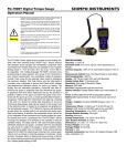
1
APPENDIX B: SETUP LIBRARY
TABLE OF CONTENTS
CHAPTER ONE: INTRODUCTION ..............................................................................2
Num
Name
Comment 1
Gn/AGC
Velocity
1
STEEL BASIC
45
0.2330 in/µSec
2
STEEL THRU PNT STD
_ 5MHZ HD
15
0.2330 in/µSec
3
STEEL THRU PNT EXT
_ 3MHZ HD
14
0.2330 in/µSec
4
ALUMINUM W/GATE
_7.5MHZ
45
0.2510 in/µSec
5
PLASTIC W/GATE THK
_ 1MHZ CPZT
45
0.0940 in/uSec
6
PLASTIC BASIC
_ 2.25MHZ
45
0.0940 in/µSec
CHAPTER TWO: QUICK STARTUP GUIDE ................................................................3
CHAPTER THREE: KEYBOARD, MENU, & CONNECTOR REFERENCE................12
CHAPTER FOUR: PRINCIPALS OF ULTRASONIC MEASUREMENT......................23
CHAPTER FIVE: SELECTING THE MEASUREMENT MODE ..................................26
CHAPTER SIX: MAKING MEASUREMENTS ............................................................29
CHAPTER SEVEN: USING THE A-SCAN & B-SCAN DISPLAYS.............................37
CHAPTER EIGHT: THRU PAINT MEASUREMENT TECHNIQUE.............................55
CHAPTER NINE: ADDITIONAL FEATURES OF THE MVX.......................................58
CHAPTER TEN: DATA STORAGE – SETUP, EDIT, & VIEW GRIDS .........................64
CHAPTER ELEVEN: SETUPS – CREATE, STORE, EDIT, & RECALL .....................74
CHAPTER TWELVE: USING THE UTILITY SOFTWARE ..........................................78
APPENDIX A: VELOCITY TABLE ...............................................................................79
APPENDIX B: SETUP LIBRARY ................................................................................80
-80-
-1-
CHAPTER ONE: INTRODUCTION
APPENDIX A -VELOCITY TABLE
The CHECK-LINE model TI-MVX is a visual A / B scan ultrasonic thickness
gauge. Based on the same operating principles as SONAR, the TI-MVX is
capable of measuring the thickness of various materials with accuracy as high
as ± 0.001 inches, or ± 0.01 millimeters. The principle advantage of ultrasonic
measurement over traditional methods is that ultrasonic measurements can be
performed with access to only one side of the material being measured.
CHECK-LINE maintains a customer support resource in order to assist users
with questions or difficulties not covered in this manual. Customer support may
be reached at any of the following:
■ ELECTROMATIC Equip’t Co. Inc.
■ Telephone: (800) 645-4330 or (516) 295-4300
■ Facsimile: (516) 295-4399
■ http://www.checkline.com
1.1
Disclaimer
Inherent in ultrasonic thickness measurement is the possibility that the instrument will use the second rather than the first echo from the back surface of the
material being measured. This may result in a thickness reading that is TWICE
what it should be. Responsibility for proper use of the instrument and recognition
of this phenomenon rest solely with the user of the instrument.
-2-
Material
sound velocity
in/us
sound velocity
m/s
Aluminum
Beryllium
Brass
Bronze
|Cadmium
Columbium
Copper
Glass (plate)
Glycerine
Gold
Inconel
Iron
Cast Iron
Lead
Magnesium
Mercury
Molybdenum
Monel
Nickel
Nylon
Platinum
Plexiglas
Polystyrene
PVC
Quartz glass
Rubber vulcanized
Silver
Steel (1020)
Steel (4340)
Steel Stainless”
Teflon
Tin
Titanium
Tungsten
Uranium
Water
Zinc
Zirconium
0.2510
0.5080
0.1730
0.1390
0.1090
0.1940
0.1830
0.2270
0.0760
0.1280
0.2290
0.2320
0.1800
0.0850
0.2300
0.0570
0.2460
0.2110
0.2220
0.1060
0.1560
0.1060
0.0920
0.0940
0.2260
0.0910
0.1420
0.2320
0.2330
0.2230
0.0540
0.1310
0.2400
0.2040
0.1330
0.0580
0.1660
0.1830
6375
12903
4394
3531
2769
4928
4648
5766
1930
3251
5817
5893
(approx) 4572
2159
5842
1448
6248
5359
5639|
(approx) 2692
3962
2692
2337
2388
5740
2311
3607
5893
5918
5664
1372
3327
6096
5182
3378
1473
4216
4648
-79-
CHAPTER TWELVE: USING THE UTILITY SOFTWARE
12.1
Turn the TI-MVX on and off using the switch located on the bottom right corner
of the keypad. When TI-MVX is initially turned on, a flash logo and blinking lights
will be displayed prior to entering into the main measurement screen. Note: This
section is primarily written as a basic startup guide only.
Computer System Requirements
MVXcomm will run on many different operating systems: Windows 95, Windows
98 (1st or 2nd edition), Windows NT 4.0 with Service Pack 5, Windows ME,
Windows XP, Windows 2000 Professional, Windows 2000 Server, or Windows
2000 Advanced Server operating systems running on Intel or AMD hardware.
A Pentium 166MHz or faster processor with at least 32 megabytes of physical
RAM is required. You should have 40 megabytes of free disk space before
attempting to install TI-MVXcomm.
MVXcomm requires an available communications port in order to transfer data
to and from the TI-MVX. MVXcomm supports COM1, COM2, COM3, and COM4.
USB to Serial Converter
Some newer laptop computers do not have standard serial ports. In this case it
is possible to use a USB to Serial converter. If a serial to USB cable is needed,
Contact CHECK-LINE (pt# N-402-0510).
12.2
CHAPTER TWO: QUICK STARTUP GUIDE
Installing TI-MVXcomm
MVXcomm comes on a CD-ROM with an automatic installer program. Place
the CD in your computer’s CD tray and close the door. Open the CD-ROM by
double clicking on the My Computer ICON, then double click on the CD.
Finally, double click on the SETUP icon to begin the installation.
Refer to the help section in MVXcomm, for the complete operating manual,
setup, and operation.
2.1
Selecting The Transducer Type
The first step in using the TI-MVX is to select the transducer type according to
frequency and diameter. By selecting the transducer type from a predefined list,
the TI-MVX can recall specific properties about the transducer. Note: Once the
transducer has been selected, the TI-MVX will store and recall this transducer
type every time the TI-MVX is powered on/off. The type will only change if the
user physically selects another transducer type from the list, or selects a previously saved setup. Therefore, if you have previously gone through this section
and selected the transducer you are using, proceed to the next section. Use the
following steps to select your transducer type.
1) Press the MENU key once to activate the menu
items tab. Press the MENU key multiple times to tab
right and the ESC key multiple times to tab left until
the PROBE menu is highlighted and displaying the
submenu items.
2) Use the UP and DOWN arrow keys to scroll
through the sub menu items until TYPE is
highlighted.
3) Press the ENTER key to display the list of
transducer types.
4) Press the UP and DOWN arrow keys to scroll
through the transducer list until the appropriate type is highlighted.
5) Press the ENTER key to display the confirmation screen.
6) Press the OK key to select the transducer and return to the menu screen, or
ESC to cancel the selecting the transducer.
-78-
-3-
2.2
Probe Zero & Calibration
13) Press the OK key to save the Setup, or ESC to cancel saving the Setup.
The next step is to calibrate the TI-MVX to the material and transducer being
used. If a sound velocity is not known, the TI-MVX can be calibrated to a known
thickness sample. This demo will briefly explain both of these techniques.
14) Finally, press the MEAS key to return to the measurement screen.
Note: The Name and Comments of the Setup can be edited at any time by simply repeating the Save Setup routine described above. Therefore, the Save
Setup function can also be considered an Edit Function.
In either case, the transducer MUST be zeroed on the probe zero disk (battery
cover located on the top of the unit as follows:
1) Apply a drop of couplant on the transducer
and place the transducer in steady contact
with the probe zero disk, and obtain a steady
reading.
2) Assuming the probe menu is still displayed
from the previous type selection, use the UP
and DOWN arrow keys to scroll through the
sub menu items until ZERO TRANSDUCER is
highlighted.
3) Press the ENTER key to display the confirmation screen.
11.4
Using the Default Setup
The default setup feature was added to the
TI-MVX to use, as a last resort, if there are no
setups stored in the gauge –factory or otherwise.
The only time this might possibly occur is if the
setup file in the TI-MVX was somehow corrupted,
and the user does not have access to a computer
to re-load the factory setups back into the TI-MVX.
This gives the user the ability to load and modify a
basic setup as follows:
1) Press the MENU key once to activate the menu
items tab. Press the MENU key multiple times to
tab right and the ESC key multiple times to tab left
until the SETUP menu is highlighted and displaying the submenu items.
2) Use the UP and DOWN arrow keys to scroll through the sub menu items until
DEFAULT SETUP is highlighted.
3) Press the ENTER key to load the Default Setup and display the Warning
Message Box.
Important Note: Remember to perform a probe zero function prior to measuring. The default setup clears the probe zero value.
4) Press the OK key to return to the measurement screen.
-4-
-77-
1) Press the MENU key once to activate the menu
items tab. Press the MENU key multiple times to
tab right and the ESC key multiple times to tab
left until the SETUP menu is highlighted and
displaying the submenu items.
4) Press the OK key to complete the probe zero function, or ESC key to cancel
the probe zero function.
2) Use the UP and DOWN arrow keys to scroll
through the sub menu items until SAVE is
highlighted.
Note: The value that is displayed will change depending on the current velocity
setting in the TI-MVX. Disregard the number that is displayed. It is not important.
What is important is accurately performing the steps outlined above to insure
reliability of the probe zero calculation.
3) Press the ENTER key to display the Save Setup
Parameters List Box.
Known Velocity
4) Press the UP and DOWN arrow keys to scroll
the Name and Note parameters.
5) When the parameter to edit is highlighted,
press the ENTER key to activate the Alpha Edit
Box.
6) Use the UP, DOWN, LEFT, and RIGHT arrow
keys to scroll through the characters, the ENTER
key to select characters, and the CLR key to
backspace through the characters, until the
Name or Note fields have been edited.
7) Press the OK key to return to the Save Setup
Parameters List Box.
8) If both parameters will be edited, repeat steps 4 – 7.
9) Use the UP and DOWN arrow keys to scroll to and highlight SAVE SETUP.
10) Press the ENTER key to activate the Setup List Box.
11) Use the UP and DOWN arrow keys to scroll
through the setups until the target location to save
the Setup is highlighted.
5) Remove the transducer from the probe zero disk, and proceed to the calibration section.
If the material velocity is known, the user may
wish to simply enter the velocity number into the
TI-MVX, rather than have the TI-MVX calculate
the velocity value on using a know thickness. The
steps for entering the velocity are outlined below:
Using a Known Material Velocity
1) Press the MENU key once to activate the menu
items tab. Press the MENU key multiple times to
tab right and the ESC key multiple times to tab left
until the CAL menu is highlighted and displaying
the submenu items.
2) Use the UP and DOWN arrow keys to scroll
through the sub menu items until VELOCITY is highlighted.
3) Press the ENTER key to display the Digits Edit Box.
4) Press the UP and DOWN arrow keys to scroll the highlighted value.
5) Press the LEFT and RIGHT arrow keys to scroll the digit locations.
6) Repeat steps 4 & 5 until the velocity number is correctly displayed.
7) Press the OK key to set the velocity and return to the menu screen, or ESC to
cancel entering the velocity.
8) Finally, press the MEAS key to return to the measurement screen and begin
taking readings.
12) Press the OK key to activate the confirmation
screen.
-76-
-5-
Known Thickness
1) Press the MENU key once to activate the menu
items tab. Press the MENU key multiple times to tab
right and the ESC key multiple times to tab left until
the SETUP menu is highlighted and displaying the
submenu items.
Sometimes the sound velocity of a material is not known. In this case a sample
with a known thickness can be used to determine the sound velocity. It would be
very handy to carry a set of mechanical calipers to use in conjunction with the
TI-MVX for calibration in the field:
2) Use the UP and DOWN arrow keys to scroll
through the sub menu items until OPEN is highlighted.
Using a Known Thickness
Note: Be sure that the probe zero procedure has been performed prior to performing this calibration procedure.
3) Press the ENTER key to display the Setup List
Box.
1) Physically measure an exact sample of the material or a location directly on
the material to be measured using a set of calipers or a digital micrometer.
2) Apply a drop of couplant on the transducer and place the transducer in steady
contact with the sample or actual test material. Be sure that the reading is stable
and the repeatability indicator, in the top left corner of the display, is fully lit and
stable. Press the MENU key once to activate the menu items tab. Press the
MENU key multiple times to tab right and the ESC key multiple times to tab left
until the CAL menu is highlighted and displaying the submenu items.
4) Use the UP and DOWN arrow keys to scroll
through the setups until the target setup is
highlighted.
5) Press the ENTER key to activate the confirmation
screen.
3) Use the UP and DOWN arrow keys to scroll through the sub menu items until
ONE POINT is highlighted.
6) Press the OK key to load the setup from memory.
4) Press the ENTER key to display the Digits Edit Box.
7) Press the MEAS key to return to the measure
screen.
5) Press the UP and DOWN arrow keys to scroll the highlighted value.
6) Press the LEFT and RIGHT arrow keys to scroll the digit locations.
7) Repeat steps 5 & 6 until the known thickness value is correctly displayed.
8) Press the OK key to calculate the velocity and return to the menu screen, or
ESC to cancel entering the velocity.
9) Finally, press the MEAS key to return to the measurement screen and begin
taking readings.
Note: CHECK YOUR CALIBRATION! Place the transducer back on the calibration point. The thickness reading should now match the known thickness. If the
thickness is not correct, repeat the steps above.
-6-
11.3
Saving a Setup
Once the TI-MVX parameters and features have be adjusted for an application,
the user may elect to save these setting to a specific setup location for future
use. This can potentially save time and reduce error between users.
It is sometimes necessary to rename a previously saved setup, or add additional
comments about a particular setup. The setup name may have been entered
incorrectly, or the user needs to use the setup for a completely different project.
An inspectors name, or other comments about the project may also be required
for additional documentation purposes. The following procedures outline the necessary steps for saving and editing a setup:
-75-
CHAPTER ELEVEN: SETUPS – CREATE, STORE, EDIT, & RECALL
11.1
Introduction to Setups
Often times, users are faced with a variety of tasks and applications that are
sometimes similar, but often times very different. With a standard thickness
gauge, the user would have to recalibrate for each individual application respectively. With all the features of the TI-MVX, the number of potential applications
also increases based on ability alone. This is primarily in reference to the addition of those very difficult applications, where a standard thickness gauge would
not be feasible, or capable of accomplishing the tasks.
The increased number of features and parameters also adds to the overall setup
time, or amount of time to set up marginal applications with perfection and
understanding. Because of the additional time involved, the TI-MVX has been
equipped with the ability to save these setups to memory and be recalled at any
time. The TI-MVX can store 64 custom setups. These setups can be bi-directionally transferred to and from a PC. Therefore, the user can save as many setups
as necessary for all of the individual applications. This saves a great deal of time
and knowledge for future inspections of the same job or project. This feature also
eliminates error between two or more users during the setup and calibration
process.
Basic Material Type
If the material velocity is unknown, and a sample thickness cannot be taken from
the material, the user may opt to choose a basic material type from a list with
approximate velocity numbers. It’s important to note that these velocities will not
always be an exact representation of the material being tested. Use these values
only if a close approximation is acceptable. Follow the steps below to select a
basic material type:
1) Press the MENU key once to activate the
menu items tab. Press the MENU key multiple
times to tab right and the ESC key multiple
times to tab left until the CAL menu is highlighted and displaying the submenu items.
2) Use the UP and DOWN arrow keys to
scroll through the sub menu items until
MATERIAL is highlighted.
3) Press the ENTER key to display the list of material types.
4) Press the UP and DOWN arrow keys to scroll through the material list until
the appropriate material is highlighted.
5) Press the ENTER key to display the confirmation screen.
11.2
6) Press the OK key to select the material and return to the menu screen, or
ESC to cancel the material selection.
Opening a Setup
The TI-MVX is loaded with a number of setups from the factory. These setups
can be opened, edited, and saved to any one of 64 setup locations. If a factory
setup is written over, the user can simply reload the default factory setups at
anytime using the utility software included with the TI-MVX. The factory setups
are general setups Only. However, they may serve as an excellent starting point,
requiring only minor adjustments to work for custom applications. It is recommended that user customized setups be saved to an empty location, and save
the factory setups for the purpose of a general starting point. The following procedures outline how to open factory and custom setups:
-74-
7) Finally, press the MEAS key to return to the measurement screen and begin
taking readings.
-7-
2.3
Measure
The TI-MVX is now ready to measure. There are four different measurement
view options, each with a specific purpose. The steps below outline how to toggle between the different view mode options:
Selecting the Measurement View Option
1) Press the MENU key once to activate the
menu items tab. Press the MENU key multiple
times to tab right and the ESC key multiple
times to tab left until the DISP menu is highlighted and displaying the submenu items.
2) Use the UP and DOWN arrow keys to scroll through the sub menu items until
OPEN is highlighted.
3) Press the ENTER key to display the Grid List
Box.
4) Use the UP and DOWN arrow keys to scroll
through the grids until the target grid is highlighted.
5) Press the ENTER key to activate the
confirmation screen.
6) Press the OK key to load the grid from memory.
2) Use the UP and DOWN arrow keys to scroll
through the sub menu items until VIEW is highlighted.
7) Press the MEAS key to return to the measure
screen.
3) Use the LEFT and RIGHT arrow keys to scroll the view options.
4) Once the view is displayed, press the MEAS key to return to measurement
mode.
RF: Is useful to see exactly what the signal looks like directly around the detect
point. Use this view only when viewing smaller ranges (zoomed in) around the
detection point. This can be done manually by adjusting the delay and width settings.
RECTIFIED (RECT): Displays the entire range being scanned. This screen is
useful to “get the big picture” when viewing wide ranges (zoomed out). The point
which is triggering the digital thickness reading (called the detect) is displayed as
a vertical dashed line.
BSCAN: The Time Based B-Scan provides the user with a cross sectional view
of the material being tested. This mode is useful when there is concern regarding the profile of the blind surface. This can also be a useful view when scanning
for pits and flaws.
-8-
-73-
8) Use the CLR key to backspace if necessary.
9) Repeat steps 6 -8 until the Comments are
completed.
DIGITS: Displays the digital thickness value using a larger font size. This view is
useful when the TI-MVX is being used as a basic thickness gauge.
Once the view has been selected according to the application requirements, the
delay and width of the screen will potentially need to be adjusted, if the view has
been set to RF, RECT, or BSCAN. Use the following steps to adjust these settings directly from the measurement screen as follows:
Adjusting the Delay & Width
10) Press the UP or DOWN arrow key to highlight SAVE CHANGES, and the OK key to
activate the confirmation screen.
11) Press the OK to save the changes or the
ESC key to cancel editing the grid parameters.
12) Press the MEAS key to return to the
measurement screen.
10.7
Changing the active grid (Open)
The user may have transferred grid templates from
a PC to the TI-MVX, or setup grids using the TI-MVX
at an earlier time. The name of the currently active
grid is always displayed at the bottom of the Hot
Menu Items in measurement mode. It’s not only
important to recognize what grid is currently active,
but also be able to change the active grid at any
time. The following procedures outline this process:
1) Press the MENU key once to activate the menu
items tab. Press the MENU key multiple times to tab
right and the ESC key multiple times to tab left until
the DATA menu is highlighted and displaying the
submenu items.
-72-
1) Press the MEAS key once to activate the measure menu items. Press the
MEAS key multiple times to move right and the ESC key multiple times to move
left, until the either the DELAY or WIDTH cell is highlighted.
2) Use the UP, DOWN, LEFT, or RIGHT arrow keys to scroll the DELAY and
WIDTH values.
3) Repeat steps 1 & 2 until the range is correctly being displayed.
Alternatively, the DELAY and WIDTH values can be changed using the Digit Edit
Box as follows:
1) Press the MEAS key once to activate measure menu items. Press the MEAS
key multiple times to move right and the ESC key multiple times to move left,
until the either the DELAY or WIDTH cell is highlighted.
-9-
2) Press the ENTER key to display the digits edit box.
3) Press the UP and DOWN arrow keys to scroll the highlighted value.
4) Press the LEFT and RIGHT arrow keys to scroll the digit locations.
10.6
Editing a grid
Once a grid has been created and saved to memory, the user can edit the
Comments or Increment Direction at a later time. The following procedures outline this process:
5) Repeat steps 3 & 4 until the DELAY or WIDTH value is correctly displayed.
6) Press the OK key to set the DELAY and WIDTH value and return to the measure screen, or ESC to cancel entering the DELAY or WIDTH value.
7) Finally, press the MEAS key to return to the measurement screen and begin
taking readings.
Note: The DELAY & WIDTH can also be adjusted from the menu tab items.
However, using the hot menu keys is the easiest method.
1) Press the MENU key once to activate the menu items tab. Press the MENU
key multiple times to tab right and the ESC key multiple times to tab left until the
DATA menu is highlighted and displaying the submenu items.
2) Use the UP and DOWN arrow keys to scroll through the sub menu items until
EDIT is highlighted.
3) Press the ENTER key to display the Edit List Box.
4) Use the UP and DOWN arrow keys to scroll through the Edit options until
NOTE or INCR. DIR is highlighted.
RF
RECTIFIED
Note: If editing the INCR. DIR, simply use the
LEFT or RIGHT arrow keys to scroll NONE,
NORTH, EAST, SOUTH, or WEST. Proceed to
step 10.
5) Press the ENTER key to activate the Alpha
Edit box – Only used when editing the NOTE.
6) Use the UP, DOWN, LEFT, & RIGHT arrow
keys to highlight the appropriate alpha
characters.
7) Press the ENTER key to select a character
and advance to the next field of the Comments.
-10-
-71-
10.5
Deleting a grid
Deleting one grid
1) Press the MENU key once to activate the
menu items tab. Press the MENU key multiple times to tab right and the ESC key multiple times to tab left until the DATA menu is
highlighted and displaying the submenu
items.
2) Use the UP and DOWN arrow keys to scroll through the sub menu items until
DELETE ONE GRID is highlighted.
3) Press the ENTER key to display the Grid
List Box.
4) Use the UP and DOWN arrow keys to
scroll through the stored Grids until the
target Grid to delete is highlighted.
5) Press the OK key to delete the Grid.
6) Press the MEAS key to return to the
measurement screen.
Deleting All Grids
1) Press the MENU key once to activate the
menu items tab. Press the MENU key multiple times to tab right and the ESC key multiple times to tab left until the DATA menu is
highlighted and displaying the
submenu items.
B-SCAN
DIGITS
In the upper left corner of each of the mode photos above, is the repeatability
indicator. The repeatability indicator is represented by six vertical bars and
represents how repeatable the measurements are. In regular measurement
mode, the TI-MVX makes 4 measurements a second. In scan mode, the TI-MVX
makes 32 measurements a second. When the TI-MVX is idle, only the left
vertical bar and the underline will be displayed. However, when the TI-MVX is
making a measurement, five or six of the bars should be displayed on the
repeatability indicator. If fewer than five bars are showing, the TI-MVX is having
difficulty achieving a stable measurement and the thickness value displayed is
potentially be unstable. Another thing to note is the vertical broken line in the RF
and RECTIFIED photos above. This line represents the actual point of detection.
The TI-MVX uses a zero crossing or flank detection method, and presents the
actual point of measurement on the display.
2) Use the UP and DOWN arrow keys to
scroll through the sub menu items until DELETE ALL GRIDS is highlighted.
3) Press the ENTER key to activate the confirmation screen.
4) Press the OK key to delete All Grids from memory, or the ESC key to abort.
5) Press the MEAS key to return to the measurement screen.
-70-
-11-
CHAPTER THREE: KEYBOARD, MENU, & CONNECTOR REFERENCE
2) Press the ENTER key to display the
Grid View Box.
3.1
3) Press the UP, DOWN, LEFT, and
RIGHT arrow keys to scroll the target cell
cursor to the desired storage location.
Menu Key (Operation & Sub Menus )
5) Press the ENTER key to save the
current reading in the highlighted cell
location.
6) Abort the Grid View Box by pressing the MEAS key at any time.
Note: Every time a reading is saved to memory, a picture of the display is automatically saved with the reading.
The Menu key activates the primary menu structure containing 9 menu tab
groups. These tab groups then contain sub menu items, or functions. The sub
menu items have been organized in tab groups according to how closely they
are related to the individual tab group names. Let’s first get familiar with how to
move around in these tabs before continuing on to the sub menu functions. This
procedure is outlined below:
Activating and Getting Around in the Menu Items
1) Press the MENU key once to activate
the menu items tab. Press the MENU key
multiple times to tab right, and the ESC key
multiple times to tab left until the desired tab
group is highlighted and displaying the
submenu items.
Now that your familiar with activating and moving amongst the tab groups, let’s
have a look at how to move around in the sub menu items as follows:
Getting Around in the Sub Menu Items
1) Use the UP and DOWN arrow keys to scroll through the sub menu items until
the desired function is highlighted.
2) Depending on which function is highlighted, use the LEFT, RIGHT, and Enter
keys to scroll the options or activate the Digit Edit and List Box options.
The sections to follow will provide the user with an explanation of the sub menu
functions:
-12-
10.4
Viewing stored readings and waveforms
It is sometimes necessary to go back and view the stored readings and waveforms using the TI-MVX without a PC. The following procedures outline this
process:
1) Press the MEAS key once to
activate measure menu items. Press
the MEAS key multiple times to move
right and the ESC key multiple times
to move left until the LOC cell is
highlighted.
2) Press the ENTER key to display the
Grid View Box.
3) Press the UP, DOWN, LEFT, and
RIGHT arrow keys to scroll the stored
readings and corresponding display view.
Notice as the cursor is moved to a different cell, the display will be updated with the display view saved with the reading.
4) The user may opt to clear a specific reading and save a new one at any time.
Press the CLR key in the appropriate cell location to clear the reading, take a
new measurement, and press the OK key to save the new reading.
5) Abort the Grid View Box by pressing the MEAS key at any time.
-69-
Saving the Grid
3.2
Probe – Menu
Zero: The TI-MVX is zeroed in much the same way that
a mechanical micrometer is zeroed. If the TI-MVX is not
zeroed correctly, all of the measurements made using
the TI-MVX may be in error by some fixed value. Refer
to the section on page 32, for an explanation of this
important procedure.
Once all the parameters are set, the user has the
option of saving or canceling the new grid.
1) Use the UP and DOWN arrow keys to scroll
through the new Grid List Items until CREATE
NEW GRID? is highlighted.
Pulse: The TI-MVX has an adjustable pulse width for both high penetration and
resolution applications. The pulse width refers to the duration of time the pulser
is on. The options are Spike, Thin, and Wide. Refer to page 58 for a further
explanation.
Type: Enables the user to select the type of transducer being used from a chart
of transducer types. This provides increased linearity between transducers. Refer
to page 30 for a further explanation.
2) Press the ENTER key to accept the grid
parameters, and activate the confirmation screen.
Units: Toggle between English or Metric units. The readout will change from inches to millimeters.
3) Press the OK key to save the New Grid, or the
ESC key to cancel the New Grid setup and return
to the DATA menu.
Velocity: Function to calibrate the TI-MVX by setting the velocity to a known
material velocity. Refer to page 33 for further info.
4) Press the MEAS key to return to the measurement screen and begin storing readings.
10.3
One Point: Performs a single point calibration. This option allows the user to
automatically calculate the velocity by entering a known sample thickness. Refer
to page 33 for further info.
Two Point: Performs a two-point calibration. This option allows the user to automatically calculate the velocity by entering a second known sample thickness.
Refer to page 34 for further info.
Storing a reading
Now that a grid has been created, it’s time to make some measurements and
store the readings. The following procedures outline this process:
Material: Select the material velocity from a chart of basic material types, when
a known sample thickness, or material velocity cannot be obtained. Refer to
page 79 for further info.
Storing a Reading
1) Press the MEAS key once to activate
measure menu items. Press the MEAS
key multiple times to move right and the
ESC key multiple times to move left until
the LOC cell is highlighted.
3.3
CAL – Menu
Units: Toggle between English or Metric units. The
readout will change from inches to millimeters.
Velocity: Function to calibrate the TI-MVX by
setting the velocity to a known material velocity.
Refer to page 33 for further info.
One Point: Performs a single point calibration. This option allows the user to
automatically calculate the velocity by entering a known sample thickness. Refer
to page 33 for further info.
-68-
-13-
Two Point: Performs a two-point calibration. This option allows the user to automatically calculate the velocity by entering a second known sample thickness.
Refer to page34 for further info.
Material: Select the material velocity from a chart of basic material types, when
a known sample thickness, or material velocity cannot be obtained. Refer to
page 36 for further info.
3.4
DISP (display) – Menu
View: Selectable RF wave, RECT (rectified) wave,
BSCAN (cross section), and DIGITS (large digits)
views. Refer to page 38 for further info.
Backlight: Selectable OFF, ON, AUTO, or INVERT
backlight option.
Contrast: Adjustable display contrast for variable light conditions.
Delay: Provides the user the ability to change where the left side of the display
window starts according to thickness, in inches or millimeters. Refer to page 46
for further info.
Width: Provides the user the ability to change the overall size of the viewable
measurement area. It functions a lot like a zoom on a camera. Refer to page
44for further info.
3) Use the LEFT, & RIGHT arrow keys to scroll the
Columns, and the UP, & DOWN arrow keys to
scroll the Rows.
4) Press the OK key to select the coordinate and
return to the Grid List Items screen, or ESC to
cancel the selection and return to the Grid List
Items menu.
Note: If there is not enough memory available to
create the grid, an error message box “NOT
ENOUGH MEMORY” will be displayed. Press the
OK or ESC key to return to the Grid List Items
menu. It may be necessary to free some memory in the TI-MVX at this time.
Refer to page 70 for more information on Deleting a Grid.
Selecting the Auto Increment Direction
The Auto Increment feature gives the user the
ability to specify which direction to advance the
cursor after storing a reading.
5) Use the UP and DOWN arrow keys to scroll
through the new Grid List Items until INCR. DIR
is highlighted.
6) Use the LEFT & RIGHT arrow keys to toggle
the Increment direction NONE, NORTH, EAST,
SOUTH, or WEST.
7) When the correct Increment direction is displayed, continue on to the next section “Saving
the Grid”.
-14-
-67-
Setting the Coordinates of the Grid
3.5
TUNE – Menu
Gain: Increases or decreases the overall amplitude
of the signal. Much like turning the volume up or
down on a stereo receiver. Refer to page 47 for
further info.
Note: A grid is defined by using coordinates to define the Top Left and the
Bottom Right corners of the grid. Alpha coordinates are horizontal across the
top, and numeric coordinates are vertical down the side. Therefore, to define the
top left corner of the grid, there will be an (X,Y) coordinate. Where X is an alpha
column location across the top and Y is a numeric row location down the side.
Use the same logic when choosing the lower right corner.
AGC: The TI-MVX is equipped with an automatic gain control when operating in
echo-echo mode only. This is much like turning the volume up or down on a
stereo receiver. However, the TI-MVX will automatically control how much the
volume is turned up or down. Alternatively, the AGC can be manually controlled
using the same procedures as GAIN described above. Refer to page 46 for
further info.
Setting the Top Left Coordinate
1) Use the UP and DOWN arrow keys to scroll
through the new Grid List Items until TOP LEFT is
highlighted.
Threshold: Enables the user to set the sensitivity level of the TI-MVX. The
amplitude of the signal must reach and exceed the threshold level before a
measurement is detected. Refer to page 48 for further info.
2) Press the ENTER key to activate the Coordinate
Edit Box.
Polarity: The TI-MVX operates on a zero crossing detection principle. This
feature toggles which stroke of the cycle the crossing detection uses, either
positive or negative. Refer to page 61 for further info.
Rect Waveform: This option provides the user an outlined or filled view option
when the display setting is in RECT (rectified) wave mode only. Refer to page
63 for further info.
3) Use the LEFT, & RIGHT arrow keys to scroll the
Columns, and the UP, DOWN arrow keys to scroll
the Rows.
4) Press the OK key to select the coordinate and
return to the Grid List Items screen, or ESC to
cancel the selection and return to the Grid List
Items menu.
Setting the Lower Right Coordinate
1) Use the UP and DOWN arrow keys to scroll
through the new Grid List Items until LOWER
RIGHT is highlighted.
2) Press the ENTER key to activate the
Coordinate Edit Box.
-66-
3.6
GATE – Menu
Measure Mode: Used to select the measurement
mode for different application requirements. The
modes are P-E (pulse-echo), P-E GT(pulse-echo
w/gate), and E-E(echo-echo). Refer to page 23 for
further info.
Gate 1: Gates allow the user to view areas or sections of the waveform and
ignore others. Gate 1 can be used in both pulse-echo and echo-echo measurement modes. Refer to page 50 for further info.
Gate 2: Gates allow the user to view areas or sections of the waveform and
ignore others. Gate 2 is only used in echo-echo measurement mode. Refer to
page 53 for further info.
-15-
3.7 SETUP – Menu
Open: Displays a list of factory and user defined setups
currently stored in memory. These setups can be
recalled and used at any time. Refer to page 74 for
further info.
Save: Provides the user with the ability to save a custom setup that has been
modified or created by the user. Refer to page 100 for further info.
5) Press the ENTER key to activate the Alpha Edit
Box.
6) Use the UP, DOWN, LEFT, & RIGHT arrow keys
to highlight the appropriate alpha characters.
7) Press the ENTER key to select a character and
advance to the next field of the Grid Name.
8) Use the CLR key to backspace if necessary.
3.8
Default Setup: Loads a basic default setup. Use only as a last resort when the
setups in the TI-MVX have been corrupted and a computer is not accessible.
Refer to page 77 for further info.
9) Repeat steps 6 -8 until the Grid Name is completed.
DATA – Menu
10) Press the OK key to save the Grid Name and
return to the Grid List Items menu, or ESC to cancel entering the Grid Name.
New: Allows the user the ability to create a new alpha
numeric grid with custom parameters, rows, and
columns depending on their application reporting
requirements. Refer to page64 for further info.
Edit: Gives the user the ability to change parameters of grid that have been previously saved. Note: Pre-defined coordinates cannot be changed once they have
been created. Refer to page 71 for further info.
Open: This function provides the user with the ability to recall grids that currently
exist in memory from a list of grids. Refer to page 72 for further info.
Delete One Grid: This function provides the user with the ability to delete one
individual grid from a list of multiple grids previously saved in memory. Refer to
page 70 for further info.
Delete All Grids: This function provides the user with the ability to delete all grids
currently stored in memory. Refer to page 70 for further info.
Creating a Grid Note
1) Use the UP and DOWN arrow keys to scroll
through the new Grid List Items until NOTE is
highlighted.
2) Press the ENTER key to activate the
Alpha Edit Box.
3) Use the UP, DOWN, LEFT, & RIGHT
arrow keys to highlight the appropriate alpha
characters.
4) Press the ENTER key to select a character
and advance to the next field of the Grid Note.
5) Use the CLR key to backspace if necessary.
6) Repeat steps 3 through 5 until the Grid Note is completed.
3.9 UTIL (utilities) – Menu
Auto Find: Automatically locates the detection point if
the measurement is out of the viewable display area.
Refer to page 59 for further info.
7) Press the OK key to save the Grid Note and return to the Grid List Items
menu, or ESC to cancel entering the Grid Note.
Scan Mode: This function enables a hi speed scan
mode that increases the overall sample rate from the
standard 4 measurements a second to 32 measurements a second. Refer to
page 59 for further info.
-16-
-65-
CHAPTER TEN: DATA STORAGE – SETUP, EDIT, & VIEW GRIDS
Alarm Status: Toggles alarm mode on or off. Refer to page 75 for further info.
10.1
Introduction to Grid (spreadsheet) format
Alarm LO Limit: Gives the user the ability to set the LO limit parameter. If the
measurement falls below this value, a red light will illuminate and sound the
internal beeper. Refer to page 61 for further info.
Data is stored in the TI-MVX in a spreadsheet like format called a GRID. A GRID
is simply a table of readings. The location in a grid is specified by giving a row
and column coordinate. The rows are numbered from 1 to 99 and the columns
are labeled from A to Z, then AA to ZZ giving a maximum of 52 possible
columns.
The largest grid that can be held in the TI-MVX is limited by the total memory of
the TI-MVX. Multiple grids can be created and stored until the TI-MVX’s memory
is full. If the user attempts to store a grid in the TI-MVX when the memory is full,
the TI-MVX will respond with an error message indicating that the memory is
unable to store the new grid.
Alarm HI Limit: Gives the user the ability to set the HI limit parameter. If the
measurement exceeds this value, a red light will illuminate and sound the internal beeper. Refer to page 61 for further info.
3.10
The TI-MVX can store a total of 12,000 readings with a corresponding waveform
stored with every reading. The waveform stored with the reading will depend on
what view the TI-MVX was in at the time it was saved. For example, If the view is
RECT, then a rectified waveform will be saved with the reading.
10.2
Restore Setups: Enables the user the ability to restore the setups currently
saved on a PC to an TI-MVX via RS232 port. Refer the help section of the
MVXview software for a complete electronic manual.
Creating a new Grid
Backup Grid: Enables the user the ability to backup grids currently stored in the
TI-MVX to a PC via RS232 port. Refer the help section of the MVXview software
for a complete electronic manual.
Important Note: This entire section is a step by
step guide to successfully create a grid. The
instructions must be used in the sequential order
specified, as follows:
Restore Grid: Enables the user the ability to restore grids currently saved on a
PC to an TI-MVX via RS232 port. Refer the help section of theMVXview software
for a complete electronic manual.
Creating a Grid Name
1) Press the MENU key once to activate the menu
items tab. Press the MENU key multiple times to
tab right, and the ESC key multiple times to tab
left, until the DATA menu is highlighted and displaying the submenu items.
2) Use the UP and DOWN arrow keys to scroll
through the sub menu items until NEW is highlighted.
3) Press the ENTER key to display the new Grid Edit Box.
XFER (transfer) – Menu
Backup Setups: Enables the user the ability to backup
the setups currently stored in the TI-MVX to a PC via
RS232 port. Refer the help section of the MVXview
software for a complete electronic manual.
About: Provides the user with CHECK-LINE contact information and the TI-MVX
software version. Refer the help section of the MVXview software for a complete
electronic manual.
3.11
CLR (clear) Key
The primary functions of the CLR key, is to clear a measurement from
a grid cell location or set obstruct, and backspace in an Alpha Edit
Box. If a user has already saved a measurement and waveform to a
cell location, use this key to clear the measurement at any time.
4) Use the UP and DOWN arrow keys to scroll through the new Grid List Items
until NAME is highlighted.
-64-
-17-
3.12
MEAS (measurement mode) Key
The MEAS key puts the TI-MVX into it’s primary mode of operation. In
this mode, the user has a complete view of the LCD, as well as control
of the Hot Menu Functions. These hot functions provide the user with
the ability to make crucial adjustments to the display, waveform settings, and grid storage locations without having to search through the menu and
sub menu items. It’s important to first get familiar with moving around in the hot
functions as follows:
Getting Around in the Hot Menus
1) Press the MEAS key at any time to return to
the primarily measurement mode.
2) Press the MEAS key multiple times to tab
right through the menu fields, and the ESC key
multiple times to tab left through the menu fields,
until the desired hot function is highlighted.
Now that you’re familiar with activating and moving amongst the hot function
fields, let’s have a look at how to adjust or change the values of these fields:
Adjusting the Values of the Hot Menus
1) Use the UP, DOWN, LEFT, and RIGHT arrow keys to increase and decrease
the values of the hot function fields.
2) Repeat step 1 until the desired value has been achieved.
Alternatively, the delay, width, gain, and threshold hot function fields can be
changed using the Digit Edit Box as follows:
1) Press the ENTER key to display the Digits Edit Box.
4) Press the MEAS key to return to the measurement screen and begin taking
readings.
Important: Be sure to do a Probe Zero after change the polarity!
9.6
Rectified Waveform (Filled/unfilled)
The TI-MVX has yet another feature primarily included for user personal viewing
preference. When the TI-MVX is in the Rectified Display View, the waveform can
be completely filled in black, or simply outlined. The procedures to toggle this
feature, are outlined below:
Toggle Rect Wave (filled / Unfilled)
Note: Before toggling the Rect Wave, the TI-MVX should be set to the RECT
display view option. Please refer to page 45 for information on selecting the
Display Views.
1) Press the MENU key once to activate
the menu items tab. Press the MENU key
multiple times to tab right, and the ESC
key multiple times to tab left, until the
TUNE menu is highlighted and displaying
the submenu items.
2) Use the UP and DOWN arrow keys to
scroll through the sub menu items until RECT WAVEFORM is highlighted.
3) Use the LEFT and RIGHT arrow keys to toggle the RECT WAVEFORM filled
or unfilled.
4) Press the MEAS key to return to the measurement screen and begin taking
readings.
2) Press the UP and DOWN arrow keys to scroll the highlighted value.
3) Press the LEFT and RIGHT arrow keys to scroll the digit locations.
4) Repeat steps 2 & 3 until the delay, width, gain, or threshold number is correctly displayed.
5) Press the OK key to set and return to the measure screen, or ESC to cancel
entering the delay, width, gain, or threshold value.
-18-
-63-
cycle altogether. This peak jump represents a
shift of the detection further out in time, resulting incorrect measurements. The material being
measured will appear thicker than it actually is.
Refer to the diagram:
Notice the +/-positions in the diagram.
The positive phase is everything above the
horizontal center line, and the negative everything below the center line. The TI-MVX uses a
zero crossing (flank) method for detection.
Therefore, the detect line (A) is represented by
the broken vertical dotted line, and is currently detecting on the negative portion
of the waveform (B) at the zero crossing (C). The signal amplitude (B) is shown
as the negative vertical height at (B) in the diagram. Refer to the height of the
second negative peak at (G). It’s clear that the amplitude of (G) is much greater
than that of (B). Therefore, if the user was measuring thick attenuative material,
and the amplitude of (B) decreased substantially, the TI-MVX would lose the first
cycle (B) and peak jump to the second cycle (F). The detect (A), would move to
(F), resulting in incorrect measurements.
3.13
3.14
3.15
1) Press the MENU key once to activate the menu items tab. Press the MENU
key multiple times to tab right, and the ESC key multiple times to tab left, until
the TUNE menu is highlighted and displaying the submenu items.
Arrow Keys
The Arrow Keys are used to navigate through the menus, increase/decrease values, and toggle specific function keys.
3.16
ENTER Key
The ENTER key is used in the overall menu selection process, to
activate list and edit boxes, and save measurements to grid locations.
3.17
Note: Before toggling the Polarity, the TI-MVX
should be set to the RF display view option.
The RF view will give the user the best
opportunity to correctly view the positive and
negative cycles of the waveform. Please refer
to page 38 for information on selecting the
Display Views.
ESC Key
The ESC key is used in the MENU, MEAS, and EDIT functions as a back or
escape function.
If the user were to select the positive phase in the diagram above, the detect
would measure at (H). (A) would move to (H). Notice the height of (D) with
respect to the height of (E) in the diagram. If the user was measuring thick attenuative material using this phase, the signal (E) will certainly be lost long before
(D). Therefore, the positive phase is a much better choice in the diagram above.
Toggle Polarity (+/-)
OK Key
The primary function of the OK key is confirmation of a change or
selection.
MULTI MODE Key
The MULTI MODE key toggles the measurement mode of the TI-MVX, from
pulse-echo (flaw mode), to echo-echo (thru paint) mode. This is a quick
automatic preset mode that enables the user to change modes without
having to manually adjust the view and gate parameters. Both modes
have been configured for use with any transducer type selected.
3.18
ON/OFF Key
The ON/OFF key simply powers the unit either ON or OFF.
Note: Unit will automatically power off when idle for 5 minutes.
All current settings are saved prior to powering off.
2) Use the UP and DOWN arrow keys to scroll through the sub menu items until
POLARITY is highlighted.
3) Use the LEFT and RIGHT arrow keys to toggle the POLARITY negative or
positive.
-62-
-19-
3.19
Top & Bottom End Caps
Setting the Alarm LO Limit
1) Assuming the ALARM STATUS is ON,
use the UP and DOWN arrow keys to scroll
through the sub menu items until ALARM
LO LIMIT is highlighted.
2) Press the LEFT and RIGHT arrow keys to scroll the value. When the correct
alarm value is being displayed, proceed to step 7.
3) Alternatively, press the ENTER key to display the Digits Edit Box.
4) Press the UP and DOWN arrow keys to scroll the highlighted value.
The top & bottom end panels are where all connections are made to the
TI-MVX. The diagram above shows the layout and description of the connectors:
5) Press the LEFT and RIGHT arrow keys to scroll the digit locations.
Transducer Connectors
6) Repeat steps 4 & 5 until the ALARM LO value is correctly displayed.
Refer to Diagram: The transducer connectors, and battery cover/probe zero disk
are located on the TI-MVX’s top end cap. The transducer connectors are of type
Lemo “00”. Note: There is no polarity associated with connecting the transducer
to the TI-MVX.
7) If only one limit will be used, press the MEAS key to return to the measurement screen and begin taking readings. Otherwise, continue on to set the
ALARM HI LIMIT.
Setting the Alarm HI Limit
Probe Zero Disk & Battery Cover
1) Assuming the ALARM STATUS is ON,use the UP and DOWN arrow keys to
scroll through the sub menu items until ALARM HI LIMIT is highlighted.
Refer to Diagram: The Battery cover is the large round disk shown in the diagram. Note: This same disk is also used as a probe zero disk. Simply remove the
cover when replacing the batteries (3 AA cells). When performing a probe zero
function, simply place the transducer on disk making firm contact. Important: Be
sure to follow the polarity labels located on the back label of the TI-MVX. Note:
Rechargeable batteries can be used, however they must be recharged outside of
the unit in a stand alone battery charger.
2) Press the LEFT and RIGHT arrow keys to scroll the value. When the correct
alarm value is being displayed, proceed to step 8.
3) Alternatively, press the ENTER key to display the Digits Edit Box.
4) Press the UP and DOWN arrow keys to scroll the highlighted value.
RS-232 Connector
5) Press the LEFT and RIGHT arrow keys to scroll the digit locations.
Refer to Diagram: The RS-232 connector, located on the bottom end cap, is a
2 pin female Lemo connector. It is designed to connect directly from the TI-MVX
to a standard AT serial port on a PC. The cable supplied with the TI-MVX is a
Lemo to 9 pin serial cable.
6) Repeat steps 4 & 5 until the ALARM HI value is correctly displayed.
7) Press the OK key to set the ALARM HI value and return to the menu screen,
or ESC to cancel entering the ALARM HI value.
8) Press the MEAS key to return to the measurement screen and begin taking
readings.
Note: This connector is also used to upgrade the TI-MVX with the latest version
of firmware.
9.5
Polarity
The TI-MVX is equipped with an option to select the polarity, or phase +/-, for the
purpose of detection. The phase can be a valuable feature to have when the signal returning from the test material is marginal, a low frequency transducer is
being used, and the user has a very weak positive or negative cycle, while trying
to measure very thick materials. There is a possibility that signal will become so
weak that it falls below the threshold, and peak jumps to the next
-20-
-61-
9.4
Alarm Mode
CHAPTER FOUR: PRINCIPALS OF ULTRASONIC MEASUREMENT
The Alarm Mode feature of the TI-MVX provides the user with a method of setting tolerances, or limits, for a particular application requirement. This feature
may be used for incoming material inspections to verify the material received is
within the manufacturer specifications. There are two limits, or alarm values, that
can be setup in the TI-MVX – ALARM LO LIMIT and ALARM HI LIMIT. However,
the user may choose to activate and utilize only one of the limit values, depending on their specific application requirements. The procedures to use the ALARM
MODE feature are outlined below:
4.1
Time versus thickness relationship
Ultrasonic thickness measurements depend on measuring the length of time it
takes for sound to travel through the material being tested. The ratio of the thickness versus the time is known as the sound velocity. In order to make accurate
measurements, a sound velocity must be determined and entered into the instrument.
The accuracy of a thickness measurement therefore depends on having a consistent sound velocity. Some materials are not as consistent as others and accuracy will be marginal. For example, some cast materials are very granular and
porous and as a result have inconsistent sound velocities.
While there are many different ultrasonic techniques to measure thickness,
which will be discussed below, all of them rely on using the sound velocity to
convert from time to thickness.
Unit Menu – Alarm Mode
4.2
Suitability of materials
Ultrasonic thickness measurements rely on passing a sound wave through the
material being measured. Not all materials are good at transmitting sound.
Ultrasonic thickness measurement is practical in a wide variety of materials
including metals, plastics, and glass. Materials that are difficult include some
cast materials, concrete, wood, fiberglass, and some rubber.
4.3
Toggle Alarm Status (on/off)
1) Press the MENU key once to activate
the menu items tab. Press the MENU key
multiple times to tab right, and the ESC
key multiple times to tab left, until the
UTIL menu is highlighted and displaying
the submenu items.
Range of measurement and accuracy
The overall measurement capabilities, based on the wide variety of materials, is
determined by the consistency of the material being measured.
The range of thickness that can be measured ultrasonically depends on the
material as well as the technique being used and the type of transducer.
Thickness measurements can be made from a minimum of
2) Use the UP and DOWN arrow keys to scroll through the sub menu items until
ALARM STATUS is highlighted.
3) Use the LEFT and RIGHT arrow keys to toggle the ALARM STATUS on/off.
4) Continue on to the next section “Setting the Alarm Lo Limit”.
-60-
-21-
0.010 inch to 9.999” in steel. However, the maximum attainable thickness is
much less for more attenuative materials (materials that absorb sound).
Using Auto Find
1) Press the MENU key once to activate
the menu items tab. Press the MENU key
multiple times to tab right, and the ESC key
multiple times to tab left, until the UTIL
menu is highlighted and displaying the
submenu items.
Accuracy, is determined by how consistent the sound velocity is through the
sound path being measured and, is a function of the overall thickness of the
material. For example, the velocity in steel is typically within 0.5% while the
velocity in cast iron can vary by 4%.
4.4
Couplant
2) Use the UP and DOWN arrow keys to scroll through the sub menu items until
AUTO FIND is highlighted.
All ultrasonic applications require some medium to couple the sound from the
transducer to the test piece. Typically a high viscosity liquid is used as the medium. The sound frequencies used in ultrasonic thickness measurement do not
travel through air efficiently. By using a liquid couplant between the transducer
and test piece the amount of ultrasound entering the test piece is much greater.
4.5
3) Place the transducer on the test material and obtain a reading.
4) Press the ENTER key to automatically adjust the display settings and bring
the waveform into view.
5) Once the signal is displayed, press the MEAS key to return to measurement
mode.
Temperature
Temperature has an effect on sound velocity. The higher the temperature, the
slower sound travels in a material. High temperatures can also damage transducers and present a problem for various liquid couplants.
Since the sound velocity varies with temperature it is important to calibrate at the
same temperature as the material being measured.
Normal temperature range: Most standard transducers will operate from
0∞F to 180∞F.
High temperature measurements: Special transducers and couplants are
available for temperatures above 180∞F up to 650∞F with intermittent contact. It
is necessary to cool the transducer, by submerging the transducer in water
between readings, when measuring high temperatures.
Modes and temperature errors: In addition to errors caused by velocity changing with temperature, some modes (measurement techniques) are affected more
than others. For example, dual element mode has larger errors due to changes
in temperature of the delay line. However, multi-echo techniques help to minimize these errors.
9.3
High Speed Scan
The High Speed Scan feature of the TI-MVX increases the overall sample rate
from the standard 4 measurements a second to 32 measurements a second.
This feature enables a user to make scanned passes over an arbitrary length of
the test material, while still maintaining a reasonable representation of thickness
over the scanned area or region. The display will continue to be updated during
the scan process, and when the transducer is removed, the TI-MVX will display
the minimum reading found. The procedure to use the SCAN MODE feature is
outlined below:
Using the Scan Mode
1) Press the MENU key once to activate
the menu items tab. Press the MENU key
multiple times to tab right and the ESC key
multiple times to tab left until the UTIL
menu is highlighted and displaying the submenu items.
2) Use the UP and DOWN arrow keys to scroll through the sub menu items until
SCAN MODE is highlighted.
3) Use the LEFT and RIGHT arrow keys to toggle the SCAN MODE on/off.
4) Press the MEAS key to return to the measurement screen.
-22-
-59-
CHAPTER NINE: ADDITIONAL FEATURES OF THE TI-MVX
9.1
Pulse Width
The TI-MVX has an adjustable pulse width option, located as a submenu item in
the PROBE tab group. Pulse width, refers to the duration of time the pulser is left
on. This time results in increased energy sent into the test material. There are
three width options (SPIKE, THIN, and WIDE). The SPIKE setting may be desirable for high resolution and general applications to decrease the overall noise.
This can be considered the normal or standard setting. When additional energy
is needed, more penetration, the THIN and WIDE options may be necessary.
The procedure to change the pulse width is outlined below:
Selecting the Pulse Width
1) Press the MENU key once to activate
the menu items tab. Press the MENU
key multiple times to tab right and the
ESC key multiple times to tab left until
the PROBE menu is highlighted and displaying the submenu items.
2) Use the UP and DOWN arrow keys to
scroll through the sub menu items until
PULSE is highlighted.
3) Use the LEFT and RIGHT arrow keys to scroll the Pulse options.
4) Once the Pulse is displayed, press the MEAS key to return to measurement
screen.
9.2
Auto Find
The TI-MVX is equipped with a very handy feature for locating the detection
point of a back wall echo that is not currently in the viewable region of the display. Suppose the TI-MVX is currently setup with a delay of 0.0” and a width of
1.0”, and the user is measuring material thickness of 2.5”. The TI-MVX will make
the correct measurement and display it digitally. However, the waveform will not
show up at all in both A-Scan views, and incorrectly in the B-Scan view without
adjusting the range of the Delay and Width accordingly.
4.6
Measurement Modes
In this section we will discuss the different measurements modes the TI-MVX is
capable of operating in, the transducers required, and the reasons for using specific modes:
Pulse-Echo Mode (Flaw & Pit detection): Pulse-echo mode measures from the
initial pulse (sometimes referred to as an artificial zero) to the first echo (reflection). In this mode, the transducer is placed on a reference disk, located on top
of the TI-MVX, and a key is pressed to establish a zero point for the particular
transducer.
V-path correction: Dual element delay line transducers have two piezoelectric
elements mounted at an angle on one end of the delay line. One element is
used for transmitting sound, while the other element only receives sound. The
two elements and their delay lines are packaged in a single housing but acoustically isolated from each other with a sound barrier. This allows the transducer
the ability to achieve very high sensitivity for detecting small defects. Also, the
surface of the test material does not have to be as flat in order to obtain good
measurements.
Dual element transducers are normally used in
pulse-echo mode for finding defects, and in echoecho mode for through coating measurements.
Dual element delay line transducers are usable
over a range of 0.025 inches to 20 inches
depending on the material, frequency,
and diameter.
A limitation of dual element delay-line transducers is the V shaped sound path.
Because the sound travels from one element to another, the time versus thickness relationship is non-linear. Therefore, a correction table in the instruments
software is used to compensate for this error.
The AUTO FIND feature is a convenient way to let the TI-MVX find the detection
point and bring the waveform signal into view automatically. The user can then
make small adjustments to the range once the signal is displayed on the screen.
-58-
Dual Element Transducer
showing V-path of signal
-23-
Echo-Echo Mode: The echo-echo mode measures
between two reflections. This technique is commonly used to eliminate errors from surface coatings
and also to make measurements in multiple layered
materials. The disadvantage is that two echoes are
needed which requires a much stronger echo
Dual Element Transducer
(reflection).
in Echo-Echo mode
Searching for small defects Dual element delay
line transducers are especially useful in searching for small defects. In the pulseecho mode with high amplifier gain, very small defects can be measured. The AScan display of the TI-MVX can be used to see the defect and optimize the
transducer placement.
Sometimes a grain particle or air bubble will cause a reflection. Without the AScan display it is impossible to know if this is a thin area or just a harmless
defect. The A-Scan allows the user to see the backwall as well as the defect similar to a flaw detector.
Waveform showing echo
signal amplitudes, we would also lose our detection of both back wall echoes.
Notice that the amplitude of the cycle just to the left of (C). The amplitude of the
cycle, at (C), is less than the amplitude of the cycle at (B), in terms of overall
height. If we decreased our gain, we would lose the first cycle (C) long before
losing the second cycle (B). Therefore, adjusting the gain or threshold levels will
not help us in this example. Our final option is adjusting the GATE2 hold-off,
shown at point (C) in the incorrect diagram, to point (B) in the correct diagram. If
we adjust the GATE2 hold-off further to the right of the first reflection, the ring
down noise from the first back wall echo no longer interferes with the true detection (D), shown in the correct diagram.
The adjustment considerations in the example above will typically be used for all
thru paint applications respectively. In some applications the hold-off may be sufficient, while a gain or threshold adjustment will solve the problem. A similar
process of elimination should be considered for all thru paint applications.
Waveform showing echo
from solid backwall
from corroded backwall
-24-
-57-
8.2
Setting Up Thru Paint Mode
4.7
Glossary of terms
The first thing to note in this section, is that by selecting the transducer type
from the list of probes stored in the TI-MVX, a basic echo-echo thru paint configuration is recalled from memory. Each of the transducers in the list contain preconfigured echo-echo settings. However, fine adjustments may be necessary in
order to be suitable for your specific applications. These configurations are general setups only. Once the transducer type has been selected and the appropriate calibration procedure completed, the TI-MVX can toggle between pulse-echo
(flaws & pits), and echo-echo (thru paint) modes by simply pressing the MULTI
MODE key located on the keypad. Refer to page 19 for additional information.
Repetition Rate & Display Update
When configuring the TI-MVX for specific thru paint applications, all of the scope
parameters will potentially be needed. The delay, width, gain, threshold, gate1,
and gate2 features will be subject to change. For this reason, they have all been
added to Hot Menu fields located directly beneath the A-Scan display for quick
and easy access. Note: Once the values of the fields have been changed or
modified, these changes must be saved to a setup location prior to powering the
TI-MVX off. Failure to do so will result in losing your changes.
Transducers have a center frequency where they are most efficient at transmitting sound (i.e. they are resonant). The TI-MVX has a variable width pulser with
three setting options (spike, thin, wide). These settings determine the period of
time the pulser turned is on. High frequency applications, where resolution is a
requirement, may require the spike or thin settings to achieve optimal results.
Low frequency applications, where more penetration is a needed, may require
the thin or wide settings, offering increased penetration. The variety of transducer frequencies and diameters used in conjunction with the pulser settings,
enable users to fine tune the TI-MVX for their application needs.
The repetition rate is how often the TI-MVX generates a burst of ultrasound.
The TI-MVX has a fixed repetition rate of 1 kHz, or 1000 times per second. The
TI-MVX updates the display 4 times per second in regular measurement mode
and 32 times a second in hi speed scan mode. Therefore, the scan mode is
most suitable for fast scans of a test piece at a lower resolution.
Variable Pulser Width
Gates
Gates control the time measurement process. They enable the user to select
measurement regions and threshold levels (sensitivity). The TI-MVX is equipped
with two gates. In pulse-echo mode a single gate can be used to eliminate noise.
In echo-echo mode both gates are used. In this mode the second gate starts
automatically after a signal is detected during the gates region, and after a user
adjustable delay, sometimes called a hold-off.
THRU-PAINT (INCORRECT)
THRU-PAINT (CORRECT)
Refer to the incorrect diagram above. Point (A) represents the detection on the
first back wall echo. The true, second back wall, reflection should be detecting at
point (D). However, the hold-off (C) is setup incorrectly and the TI-MVX is detecting the ring down noise of the transducer, on the first reflection, rather than the
true second back wall reflection shown at (D).
Before we look at the diagram with the correct configuration, let’s consider all
of our options on how to fix the problem beforehand. Our delay and width will
simply change the view options of the screen – not needed in this example.
Will a gain or threshold adjustment fix the problem? Unfortunately, not. Why?
Notice the amplitude of the cycle just to the left of (B). If we tried to increase the
threshold level above the height of the cycle, we would lose our detection for
both echoes resulting in no reading at all, If we decrease our gain, reducing the
-56-
-25-
CHAPTER FIVE: SELECTING THE MEASUREMENT MODE
CHAPTER EIGHT: THRU PAINT MEASUREMENT TECHNIQUE
5.1
8.1 I
The setup library
The TI-MVX contains 64 user configurable preset locations to store custom
setups for easy recall. These setups can be optimized for the user’s specific
application needs and can also be stored on a PC and transferred bi-directionally using Dakota’s PC interface software included with the instrument.
The setups supplied with the instrument cover some of the more typical applications commonly used with this type of instrument. These setups can be recalled,
modified, and overwritten to one of 64 setup locations. Therefore, these factory
setups can also be considered a good starting point to be modified for custom
applications. The PC software includes a default setup file that can be uploaded
to the gauge at any time to restore factory settings. However, it is recommended
that the user consider saving modified setups to an empty location rather than
overwriting the factory setups in the TI-MVX. Once again, these factory settings
are excellent starting points for custom setups.
5.2
Which mode & transducer do I use for my application?
High penetration plastics and castings
The most common mode for these types of applications is pulse-echo. Select a
low frequency transducer. Depending on the thickness of the material, use a
2.25MHz or lower frequency transducer. Larger diameters offer greater penetration power because of the crystal size, for difficult to measure materials.
Corrosion & Pit Detection in steel
Use pulse-echo mode whenever attempting to locate pits and flaws. Typically a
5MHz transducer, or higher, will be used for these types of applications. Use low
frequencies for greater penetration and use higher frequencies for better resolution.
Thru Paint & Coatings
Often times users will be faced with applications where the material will be coated with paint or some other type of epoxy material. Since the velocity of the
coating is approximately 2.5 times slower than that of steel, pulse-echo mode
will induce error if the coating or paint is not completely removed. By using echoecho mode, the user is able to successfully measure through both, the coating
and steel, and completely eliminate the thickness of the paint or coating.
Therefore, the steel can be measured without having to remove the coating prior
-26-
Introduction to Thru Paint Measurement
The principle behind thru paint measurement is by measuring the time between
two backwall echoes returning from the test material. Since both of these backwall echoes travel the same path through the paint or coating, the thickness of
the coating is subtracted out of the measurement so that only the actual material
thickness can be measured. This feature saves the user a great deal of time
scraping and removing the coating from tanks and pipes during the inspection
process.
The primary purpose of thru paint measurement is to determine actual or overall
material thickness by eliminating the coating thickness. Thru paint mode cannot
be used for flaw or pit detection. Therefore, inspectors will use this echo-echo
thru paint mode in conjunction with a standard pulse-echo flaw detection mode.
The combination of using both modes is ideal for the advanced inspectors
needs.
ECHO – ECHO MODE (THRU PAINT ) – TWO GATES
Refer to the diagram above. This is a typical
example of an echo-echo mode setup commonly used for a through paint or coatings
application. Once again, the definition of an
echo-echo measurement, is a measurement
taken between to return echoes, rather than
from the initial pulse to a single echo.
Therefore, the measurement is taken
between the first and second echo reflections. Point (C) represents the detection on
the back wall of the first reflection. Notice that
GATE1 has been has been set up so that the TI-MVX can only see the first back
wall reflection (C), and cannot see anything before the first reflection. Remember
that the TI-MVX can only see those signals inside the dimensions of the gate.
GATE2 (hold-off) has been set at point (B), so that the transducer ring down
noise following the first detection (C) can’t interfere with the second back wall
reflection (D). The distance from point (C), which is the end of the first gate (A),
to the start of GATE2 (B), is the hold-off time or delay. This type of setup allows
the user to eliminate the paint or coating, and measure only metal the thickness
of the metal.
-55-
Alternatively, Gate 2 can be selected from the menus and adjusted as follows:
1) Press the MENU key once to activate the menu
items tab. Press the MENU key multiple times to
tab right and the ESC key multiple times to tab left
until the GATE menu is highlighted and displaying
the submenu items.
2) Use the UP and DOWN arrow keys to scroll
through the sub menu items until GATE 2 is highlighted.
3) Press the LEFT and RIGHT arrow keys to scroll
the value. When the correct gate value is being
displayed, proceed to step 8.
4) Alternatively, press the ENTER key to display
the Digits Edit Box.
5) Press the UP and DOWN arrow keys to scroll the highlighted value.
6) Press the LEFT and RIGHT arrow keys to scroll the digit locations.
7) Repeat steps 5 & 6 until the GATE 2 value is correctly displayed.
8) Press the OK key to set the gate and return to the menu screen, or ESC to
cancel entering the gate value.
9) Finally, press the MEAS key to return to the measurement screen and begin
taking readings.
to measuring. Users will often use pulse-echo mode and echo-echo mode in
conjunction when performing inspections on coated materials.
Thru coating measurements require special high damped transducers. The most
common transducers are the 3.5, 5, and 7.5MHz hi damped transducers. These
transducers are suitable for use in both pulse-echo and echo-echo modes. This
conveniently enables the user to accurately measure overall material thickness
using the thru Coating mode, and then conveniently switch to pit detection mode
without changing transducers.
Thin materials
Use pulse echo mode and a high frequency transducer for these types of applications. The most common transducers are the 7.5MHz and 10MHz models with
extra resolution. The higher frequencies provide greater resolution and a lower
minimum thickness rating overall.
High temperature
Use and select a special 2.25MHz and 5 MHz High temperature transducer for
these types of applications. Both pulse-echo and echo-echo modes will also
work for these applications. However, echo-echo mode will eliminate error
caused by temperature variations in the delay line of the transducer.
Noisy Material
Materials such as titanium, stainless steel, and aluminum may have inherent surface noise issues. This is a signal that appears at the surface of the material
when using a dual element delay line probe. Select a higher frequency transducer to reduce this noise – 7.5MHz and higher for better resolution. Alternatively,
enable a single gate to block this noise. See the section Gate 1 on page 50 for
more information.
Restricted access
In order to measure materials with lots of curvature or restricted access, use and
select higher frequencies with smaller diameters. The smallest diameter uses
3/16” crystals with a contact area of .250”.
-54-
-27-
5.3
Factory Setup Chart
Num
1
2
3
4
5
6
Name
STEEL BASIC
STEEL THRU PNT STD
STEEL THRU PNT EXT
ALUMINUM W/GATE
PLASTIC W/GATE THK
PLASTIC BASIC
5) Press the UP and DOWN arrow keys to scroll the highlighted value.
Comment 1
_ 5MHZ HD
_ 3MHZ HD
_” 7.5MHZ
_ 1MHZ CPZT
_ 2.25MHZ
Gn/AGC
45
15
14
45
45
45
Velocity
0.2330 in/uSec
0.2330 in/uSec
0.2330 in/uSec
0.2510 in/uSec
0.0940 in/uSec
0.0940 in/uSec
6) Press the LEFT and RIGHT arrow keys to scroll the digit locations.
7) Repeat steps 5 & 6 until the gain number is correctly displayed.
8) Press the OK key to set the Gate 1 value and return to the menu screen, or
ESC to cancel entering the Gate 1 value.
9) Finally, press the MEAS key to return to the measurement screen and begin
taking readings.
Gate 2
The GATE 2 HOLDOFF is only used in the echo-echo mode. Note: The TI-MVX
must be in E-E (echo-echo) mode to be activated. GATE 2 is sometimes called a
Hold-Off or Delay. The function of the GATE HOLDOFF is to prevent the second
gate from triggering on noise associated with ring down of the first echo. The
GATE 2 HOLDOFF is visible as the distance from the end of GATE 1 at the first
detect, to the start of GATE 2 as display by the horizontal bars on the display. A
further explanation suggests the HOLDOFF is a time delay that simply extends
the end of GATE 1 further out in time to prevent GATE 2 from starting. This is
commonly used to avoid detecting interface noise or transducer ring down. The
diagrams below provide a visual example of the gates, followed by the procedures to adjust the gates for different applications:
Adjusting Gate2 using the Hot Menus
1) Press the MEAS key once to activate measure
menu items. Press the MEAS key multiple times
to move right and the ESC key multiple times to
move left, until the GATE2 cell is highlighted.
2) Press the UP, DOWN, LEFT, and RIGHT
arrow keys to scroll the highlighted value.
3) Alternatively, press the ENTER key to display
the Digits Edit Box.
4) Press the UP and DOWN arrow keys to scroll
the highlighted value.
5) Press the LEFT and RIGHT arrow keys to
scroll the digit locations.
6) Repeat steps 4 & 5 until the GATE2 value is correctly displayed.
7) Press the OK key to return to the measurement screen, or ESC to cancel
entering the GATE 2 value.
-28-
-53-
brings all the fine adjustments into consideration, and demonstrates the versatility of having fully functional scope rather than a basic digital thickness gauge.
CHAPTER SIX: MAKING MEASUREMENTS
The steps involved in making measurements are detailed in this section. The
following sections outline how to setup and prepare your TI-MVX for field use.
Adjusting Gate1 using the Hot Menus
1) Press the MEAS key once to activate measure
menu items. Press the MEAS key multiple times
to move right and the ESC key multiple times to
move left until the GATE 1 cell is highlighted.
In pulse-echo modes, the probe zero must be measured on the reference disk
(battery disk) attached to the top of the instrument. This compensates for variation in the transducer. In all modes the sound velocity must be determined. The
sound velocity is used to convert the transit time to a physical length. The sound
velocity can be selected from a material chart in the manual, selected from a
material list in the TI-MVX, or for greater precision, determined from a sample of
the test material that has been mechanically measured. To enter the velocity
from a table, look up the material on the chart in the appendix of this manual
and refer to the section below on Calibration to a Known Velocity. To determine
the velocity of a single sample, refer to the Material Calibration section on page
32.
2) Press the UP, DOWN, LEFT, and RIGHT arrow
keys to scroll the highlighted value.
3) Alternatively, press the ENTER key to display
the Digits Edit Box.
4) Press the UP and DOWN arrow keys to scroll
the highlighted value.
When measuring curved materials, it is more accurate to calibrate from two test
points, one at the minimum limit of the target thickness and one at the maximum
limit. In this case the reference disk mounted to the TI-MVX is not used. This is
called two-point calibration and is described on page 34.
5) Press the LEFT and RIGHT arrow keys to
scroll the digit locations.
6) Repeat steps 4 & 5 until the GATE 1 value is correctly displayed.
7) Press the OK key to return to the measurement screen, or ESC to cancel
entering the GATE 1 value.
The user can also access and adjust the gate from the tabbed menus. However,
this method is more tedious than making the adjustments using the Hot Menus.
The procedure using the tabbed menus is outlined below:
Adjusting Gate1 using the Tabbed menus
1) Press the MENU key once to activate the menu
items tab. Press the MENU key multiple times to
tab right and the ESC key multiple times to tab
left until the GATE menu is highlighted and displaying the submenu items.
2) Use the UP and DOWN arrow keys to scroll
through the sub menu items until GATE is highlighted.
6.1
Selecting The Transducer Type
The first step in using the TI-MVX is to select the transducer type from the
transducer list located in the tabbed menu items by frequency and diameter.
By selecting the transducer type from a predefined list, the TI-MVX can recall
specific properties about the transducer. Note: Once the transducer has been
selected, the TI-MVX will store and recall this transducer type every time the
TI-MVX is powered on/off. The type will only change if the user physically selects
another type from the list, or selects a previously saved setup. Therefore, if you
have previously gone through this section and selected the transducer you are
using, proceed to the next section. Use the following steps to select your transducer type.
Note: Be sure the transducer type selected is the same as the transducer
plugged into the TI-MVX. Failure to do this will result in erroneous measurements
3) Press the LEFT and RIGHT arrow keys to
scroll the value. When the correct gate is being
displayed, proceed to step 8.
4) Alternatively, press the ENTER key to display
the Digits Edit Box.
-52-
-29-
Selecting the Transducer Type
SURFACE NOISE PROBLEM
1) Press the MENU key once to activate the menu
items tab. Press the MENU key multiple times to
tab right and the ESC key multiple times to tab
left until the PROBE menu is highlighted and
displaying the submenu items.
2) Use the UP and DOWN arrow keys to scroll
through the sub menu items until TYPE is
highlighted.
3) Press the ENTER key to display the list of
transducer types.
4) Press the UP and DOWN arrow keys to scroll
through the transducer list until the appropriate type is highlighted.
5) Press the ENTER key to display the confirmation screen.
6) Press the OK key to select the transducer and return to the menu screen, or
ESC to cancel the material selection.
Now that the proper transducer has been selected and connected to the TI-MVX,
the measurement mode must be chosen according to the type of application.
Following the recommendations in the prior chapter, there are three different
ways to select the measurement mode as follows:
Selected from a Setup
Important Note: Stored setups will save all the
parameters of the TI-MVX. Therefore, if a transducer was selected in the previous section and a
setup is now being recalled, the transducer saved
in the setup will overwrite the transducer previously
selected. Be sure the transducer saved with the
setup is the same as the transducer currently
being used. Alternatively, you can select a transducer again after recalling a setup. This will override the transducer saved with the setup.
1) Press the MENU key once to activate the menu
items tab. Press the MENU key multiple times to
tab right and the ESC key multiple times to tab left
until the SETUP menu is highlighted and displaying the submenu items.
2) Use the UP and DOWN arrow keys to scroll through the sub menu items until
OPEN is highlighted.
-30-
NO GATE
W/GATE
The diagrams above illustrate a typical surface noise condition. Refer to the NO
GATE diagram: (A) refers to the noise in front of the actual back wall signal (C).
Notice that without a gate activated, the TI-MVX is detecting on the noise (A) as
shown at point (B). However, the true measurement should be taken at point (C).
Given the threshold and gain levels the TI-MVX is currently set to in the NO
GATE diagram, the amplitude from the noise is sufficient enough to cause the
TI-MVX to detect, or measure the noise rather than the true back wall thickness
(C). Therefore, the TI-MVX is making an incorrect reading at point (B).
Now refer to the W/GATE diagram. The horizontal line at the top of (D), is
GATE1. The start point of GATE1 has been adjusted to just beyond the noise (A)
so that the TI-MVX ignores the noise and detects the true back wall (C). Note:
the TI-MVX will only detect on signals that are located inside the dimensions of
GATE1 (B). Therefore, the TI-MVX cannot see (A) at all, with respect to the starting point of (B). Also notice, the THR (threshold) level is the height of the distance (D) from the baseline. Zero threshold is indicated by the bottom of the
range (D), and THR: 6 (threshold) is indicated at the top of the range at (D).
Therefore, the vertical height of GATE1 is the THR (threshold) level. The threshold level can be increased to decrease sensitivity, or decreased to increase sensitivity.
If the threshold level was increased in the NO GATE diagram, so that the level
was higher than the amplitude of the noise (A), the TI-MVX would have detected
on the true back wall (C). Alternatively, if the gain level was decreased, the signal amplitude of the noise (A) would have decreased below the threshold level,
and the TI-MVX would have also detected the true back wall (C). This example
-51-
7.6
7) Repeat steps 5 & 6 until the Threshold number is correctly displayed.
3) Press the ENTER key to display the list of stored setups.
8) Press the OK key to set the Threshold and return to the menu screen, or
ESC to cancel entering the Threshold.
4) Press the UP and DOWN arrow keys to scroll through the list of setups until
the appropriate setup is highlighted.
9) Finally, press the MEAS key to return to the measurement screen and begin
taking readings.
5) Press the ENTER key to display the confirmation screen.
Gates
The TI-MVX is equipped with two gates that can be adjusted by the user to
measure a specific region or area on and between waveforms. In pulse -echo,
only a single gate can be used. The single gate has a threshold and a start
point. In echo -echo mode, two gates are used. The same threshold level is
associated with both gates. The first gate has a starting point and threshold, and
the second gate has a start time that is determined by adding an adjustable
HOLD OFF, or delay, to the return echo measured by the first gate. These
features are described in more detail below:
Note: In order to adjust the gates they must be activated. The gates will only be
active if the measurement mode is set to P-E GT (pulse – echo w/gate1), or E-E
(echo – echo w/ gates 1&2). If the gates are not active, they will be grayed out in
the hot and tabbed menus. The explanations that follow assume that the proper
measurement mode has been selected. Refer to page 26 for additional information on selecting the measurement mode.
Gate 1
6) Press the OK key to select the setup and return to the menu screen, or ESC
to cancel the selection process.
7) Press the MEAS key to return to the measurement screen.
Alternatively, the measurement mode can be simply selected from the Hot Menu
Items or selected from a sub menu feature as follows:
Hot Menu Selection
1) Press the MEAS key once to activate
measure menu items. Press the MEAS
key multiple times to move right and the
ESC key multiple times to move left, until
the MODE cell is highlighted.
2) Use the UP, DOWN, LEFT, or RIGHT
arrow keys to scroll the modes P-E (pulse-echo flaws and pits), P-E GT (pulseecho flaws and pits w/gate), and E-E (echo-echo thru paint w/2 gates) until the
target mode is selected.
Finally, the measurement mode can be selected from the menu items as follows:
GATE 1 is used in both pulse-echo and echo-echo modes. It has a threshold and
a start time. The purpose of GATE 1 is to prevent the TI-MVX from measuring
unwanted surface noise. This is accomplished by changing the start time of
GATE 1. It may be advantageous to activate a gate when measuring aluminum,
titanium, and stainless steel using lower frequency transducers. However, if a
high frequency transducer is being used, the gate may not be necessary.
Aluminum sometimes has an inherent surface noise problem that can cause
erroneous readings from the noise just following the initial pulse. By blocking the
surface noise with GATE 1 this error is eliminated. GATE 1 is also used in echo echo mode to force the TI-MVX to measure between the first and second back
wall echoes, by moving the start to the first back wall reflection of the test material.
The procedures to adjust Gate 1 are outlined below:
-50-
Selected Using The Tabbed Submenu Items
1) Press the MENU key once to activate the
menu items tab. Press the MENU key multiple times to tab right and the ESC key multiple times to tab left until the GATE menu is
highlighted and displaying the submenu
items.
2) Use the UP and DOWN arrow keys to
scroll through the sub menu items until MEASURE MODE is highlighted.
3) Use the LEFT and RIGHT arrow keys to scroll the mode options. Once the
mode is displayed, press the MEAS key to return to the measurement mode
screen.
-31-
6.2
Probe Zero
Adjusting the Threshold using the Hot Menus
As noted in chapter 3, the probe zero function is a very important and necessary
function that must done prior to calibration. It should also be done on a regular
basis. If the TI-MVX is not zeroed correctly, all of the measurements taken, may
be in error by some fixed value. In order to perform a probe zero, the TI-MVX
must be in pulse-echo mode. If echo-echo mode was previously selected in the
last section, skip this section and continue on to the next. Note: If you intend to
switch between measurement modes simultaneously, temporarily select the
pulse-echo mode using the hot menu option, perform the probe zero function,
and switch back to echo-echo measurement mode after zeroing. The following
steps outline the procedure for performing a probe zero:
1) Press the MEAS key once to activate measure
menu items. Press the MEAS key multiple times
to move right and the ESC key multiple times to
move left, until the THR (threshold) cell is highlighted.
Performing a Probe Zero
1) Clean the surface of the Probe Zero
Disk, located on top of the TI-MVX
(battery cover).
2) Apply a drop of couplant to the end of
the transducer, or probe disk, and hold
the transducer in steady contact with the
reference disk.
3) Press the MENU key once to activate the menu items tab. Press the MENU
key multiple times to tab right and the ESC key multiple times to tab left until the
PROBE menu is highlighted and displaying the submenu items.
4) Use the UP and DOWN arrow keys to scroll through the sub menu items until
ZERO TRANSDUCER is highlighted.
5) Press the ENTER key to display the confirmation screen.
6) Press the OK key to zero the transducer and return to the menu screen, or
ESC to cancel the zeroing process.
7) Remove the transducer from the probe zero disk.
8) Press the MEAS key to return to the measurement screen.
6.3
Material Calibration
In order for the TI-MVX to make accurate measurements, it must be set to the
correct sound velocity of the material being measured. Different types of materials have different inherent sound velocities. For example, the velocity of sound
through steel is about 0.233 inches per microsecond, versus that of aluminum,
which is about 0.248 inches per microsecond. If the gauge is not set to the correct sound velocity, all of the measurements the gauge makes will be erroneous
by some fixed percentage.
-32-
2) Press the UP, DOWN, LEFT, and RIGHT
arrow keys to scroll the highlighted value.
3) Alternatively, press the ENTER key to display
the Digits Edit Box.
4) Press the UP and DOWN arrow keys to scroll
the highlighted value.
5) Press the LEFT and RIGHT arrow keys to scroll the digit locations.
6) Repeat steps 4 & 5 until the THR value is correctly displayed.
7) Press the OK key to return to the measurement screen, or ESC to cancel
entering the THR.
The user can also access and adjust the Threshold from the tabbed menus.
However, this method is more tedious than making the adjustments using the
Hot Menus. The procedure using the tabbed menus is outlined below:
Adjusting the Threshold using the Tabbed Menus
1) Press the MENU key once to activate the menu
items tab. Press the MENU key multiple times to tab
right, and the ESC key multiple times to tab left,
until the TUNE menu is highlighted and displaying
the submenu items.
2) Use the UP and DOWN arrow keys to scroll
through the sub menu items until THRESHOLD is
highlighted.
3) Press the LEFT and RIGHT arrow keys to scroll
the value. When the correct threshold is being displayed, proceed to step 8.
4) Alternatively, press the ENTER key to display the
Digits Edit Box.
5) Press the UP and DOWN arrow keys to scroll the highlighted value.
6) Press the LEFT and RIGHT arrow keys to scroll the digit locations.
-49-
Adjusting the Gain using the Tabbed Menus
1) Press the MENU key once to activate the menu
items tab. Press the MENU key multiple times to tab
right, and the ESC key multiple times to tab left, until
the TUNE menu is highlighted and displaying the
submenu items.
2) Use the UP and DOWN arrow keys to scroll
through the sub menu items until GAIN is highlighted.
3) Press the LEFT and RIGHT arrow keys to scroll
the value. When the correct Gain is being displayed,
proceed to step 8.
4) Alternatively, press the ENTER key to display the Digits Edit Box.
5) Press the UP and DOWN arrow keys to scroll the highlighted value.
7.5
The One Point calibration is the simplest and most commonly used calibration
method -optimizing linearity over large ranges. The Two Point calibration allows
for greater accuracy over small ranges by calculating the probe zero and velocity. The TI-MVX provides four simple methods for setting the sound-velocity outlined below:
Calibration to a known velocity
1) Press the MENU key once to activate the menu
items tab. Press the MENU key multiple times to
tab right, and the ESC key multiple times to tab left,
until the CAL menu is highlighted and displaying
the submenu items.
2) Use the UP and DOWN arrow keys to scroll
through the sub menu items until VELOCITY is
highlighted.
6) Press the LEFT and RIGHT arrow keys to scroll the digit locations.
3) Press the ENTER key to display the Digits Edit
Box.
7) Repeat steps 5 & 6 until the Gain value is correctly displayed.
4) Press the UP and DOWN arrow keys to scroll the highlighted value.
8) Press the OK key to set the Gain and return to the menu screen, or ESC to
cancel entering the Gain.
5) Press the LEFT and RIGHT arrow keys to scroll the digit locations.
9) Finally, press the MEAS key to return to the measurement screen and begin
taking readings.
7) Press the OK key to set the velocity and return to the menu screen, or ESC to
cancel entering the velocity.
Threshold
8) Finally, press the MEAS key to return to the measurement screen and begin
taking readings.
The Threshold is the level (sensitivity) of the signal amplitude required to trigger
the thickness reading. This level can be used in conjunction with the gain.
Example: suppose the user can visually see a potential flaw on the display, but
the TI-MVX is not detecting on the flaw because the Gain is too low, or the
Threshold to high. The Threshold level can be decreased (lower sensitivity) in
order to detect signals with lower amplitudes. This will allow the amplitude from
the reflection of the flaw to reach and exceed the Threshold level, and enable
the TI-MVX to detect on the flaw or defect. This can also be accomplished by
increasing the Gain, allowing the signal to exceed the current Threshold level.
Lowering the Threshold (increases sensitivity), and raising the Threshold
decreases the sensitivity respectively.
-48-
6) Repeat steps 4 & 5 until the velocity number is correctly displayed.
One Point Calibration
Note: Be sure that a probe zero has been done
prior to performing this calibration procedure.
1) Physically measure a location on the sample to
be measured using a set of calipers or a digital
micrometer. Note: It’s always best to calibrate on
thickest location on the sample, rather than on the
thinnest location, as the percentage error is much
less with respect to the TI-MVX’s resolution of
+/-.001” (0.01mm).
-33-
2) Apply a drop of couplant on the transducer. Place the transducer in steady
contact on the known thickness location. Be sure that the reading is stable and
the repeatability indicator, located in the top left corner of the display, is fully lit
and stable. Press the MENU key once to activate the menu items tab. Press the
MENU key multiple times to tab right and the ESC key multiple times to tab left
until the CAL menu is highlighted and displaying the submenu items.
3) Use the UP and DOWN arrow keys to scroll through the sub menu items until
ONE POINT is highlighted.
4) Press the ENTER key to display the Digits Edit Box.
5) Press the UP and DOWN arrow keys to scroll the highlighted value.
6) Press the LEFT and RIGHT arrow keys to scroll the digit locations.
7) Repeat steps 5 & 6 until the known thickness value is correctly displayed.
8) Press the OK key to calculate the velocity and return to the menu screen,
or ESC to cancel entering the velocity.
7) Repeat steps 5 & 6 until the Delay number is correctly displayed.
8) Press the OK key to set the Delay and return to the menu screen, or ESC to
cancel entering the Delay.
9) Finally, press the MEAS key to return to the measurement screen and begin
taking readings.
7.4
Gain
The gain, or amplification of the return echoes, can be adjusted over a wide
range. The setting of the gain is crucial in order to obtain valid readings during
the measurement process. Too much gain may result in erroneous measurements, by detecting on noise rather than the actual material back wall itself. Too
little gain may result in detection on an undesirable section of the waveform. It
may also result in lack of detection on internal flaws or pits. The gain can easily
be compared to the volume control of a home stereo system. If you turn it up too
much, you can’t hear the music clearly. If it’s turned down too much, you can’t
hear it at all.
9) Finally, press the MEAS key to return to the measurement screen and begin
taking readings.
Adjusting the Gain using the Hot Menus
Note: CHECK YOUR CALIBRATION! Place the transducer back on the
calibration point. The thickness reading should now match the known thickness.
If the thickness is not correct, repeat the steps above.
1) Press the MEAS key once to activate measure
menu items. Press the MEAS key multiple times to
move right, and the ESC key multiple times to move
left until the GAIN cell is highlighted.
Two Point Calibration
Note: Be sure that a probe zero has been done prior to performing this calibration procedure.
2) Press the UP, DOWN, LEFT, and RIGHT arrow keys
to scroll the highlighted value.
3) Alternatively, press the ENTER key to display the
Digits Edit Box.
4) Press the UP and DOWN arrow keys to scroll the
highlighted value.
5) Press the LEFT and RIGHT arrow keys to scroll the digit locations.
6) Repeat steps 4 & 5 until the GAIN value is correctly displayed.
7) Press the OK key to return to the measurement screen, or ESC to cancel
entering the GAIN.
The user can also access and adjust the gain from the tabbed menus. However,
this method is more tedious than making the adjustments using the Hot Menus. :
-34-
-47-
Adjusting the Delay using the Hot Menus
1) Press the MEAS key once to activate measure menu items. Press the MEAS key multiple
times to move right and the ESC key multiple
times to move left, until the DELAY cell is highlighted.
2) Press the UP, DOWN, LEFT, and RIGHT
arrow keys to scroll the highlighted value.
3) Alternatively, press the ENTER key to display
the Digits Edit Box.
4) Press the UP and DOWN arrow keys to scroll
the highlighted value.
1) Using a set of calipers, physically measure two known thickness locations on
the sample of material. Note: The two locations should represent the desired
thickness range being measured. If the range is from .250” -1.000”, then the two
known locations should represent this range, or be slightly outside or inside of
this range. A typical example would be to find two locations at .236” and the
other at 1.047”. These thickness points will satisfy the required thickness range
noted above.
2) Apply a drop of couplant on the transducer. Place the transducer in steady
contact on thickest known location first. Be sure that the reading is stable and
the repeatability indicator, located in the top left corner of the display, is fully lit
and stable. Press the MENU key once to activate the menu items tab. Press the
MENU key multiple times to tab right, and the ESC key multiple times to tab left,
until the CAL menu is highlighted and displaying the submenu items.
5) Press the LEFT and RIGHT arrow keys to scroll the digit locations.
3) Use the UP and DOWN arrow keys to scroll through the sub menu items until
ONE POINT is highlighted.
6) Repeat steps 4 & 5 until the DELAY value is correctly displayed.
4) Press the ENTER key to display the Digits Edit Box.
7) Press the OK key to return to the measurement screen, or ESC to cancel
entering the DELAY.
5) Press the UP and DOWN arrow keys to scroll the highlighted value.
The user can also access and adjust the delay from the tabbed menus.
However, this method is more tedious than making the adjustments using the
Hot Menus. The procedure using the tabbed menus is outlined below:
7) Repeat steps 5 & 6 until the known thickness value is correctly displayed.
Adjusting the Delay using the Tabbed Menus
1) Press the MENU key once to activate the menu
items tab. Press the MENU key multiple times to tab
right, and the ESC key multiple times to tab left, until
the DISP menu is highlighted and displaying the submenu items.
2) Use the UP and DOWN arrow keys to scroll
through the sub menu items until DELAY is
highlighted.
3) Press the LEFT and RIGHT arrow keys to scroll
the value. When the correct Delay is being displayed,
proceed to step 8.
4) Alternatively, press the ENTER key to display the
Digits Edit Box.
5) Press the UP and DOWN arrow keys to scroll the highlighted value.
6) Press the LEFT and RIGHT arrow keys to scroll the digit locations.
-46-
6) Press the LEFT and RIGHT arrow keys to scroll the digit locations.
8) Press the OK key to calculate the velocity for the ONE POINT calibration and
return to the CAL menu screen, or press ESC to cancel entering the velocity.
9) Apply a drop of couplant on the transducer and place the transducer in steady
contact with the sample or actual test material on the thinnest, or second known
thickness location. Be sure that the reading is stable and the repeatability indicator, located in the top left corner of the display, is fully lit and stable.
10) Use the UP and DOWN arrow keys to highlight the TWO POINT calibration
submenu item.
11) Press the ENTER key to display the Digits Edit Box.
12) Press the UP and DOWN arrow keys to scroll the highlighted value.
13) Press the LEFT and RIGHT arrow keys to scroll the digit locations.
14) Repeat steps 12 & 13 until the known thickness value is correctly displayed.
15) Press the OK key to calculate the velocity for the TWO POINT calibration
and return to the CAL menu screen, or press ESC to cancel entering the
velocity.
16) Finally, press the MEAS key to return to the measurement screen and begin
taking readings.
-35-
Note: CHECK YOUR CALIBRATION! Place the transducer back on both calibration points. The thickness readings should now match
the known thickness locations. If they are not correct,
repeat the steps above.
Built in Material Selection
1) Press the MENU key once to activate the menu
items tab. Press the MENU key multiple times to tab
right, and the ESC key multiple times to tab left, until
the CAL menu is highlighted and displaying the submenu items.
2) Use the UP and DOWN arrow keys to scroll
through the sub menu items until MATERIAL is
highlighted.
3) Press the ENTER key to display the list of Material Types.
Adjusting the Width using the Tabbed Menus
1) Press the MENU key once to activate the menu
items tab. Press the MENU key multiple times to tab
right, and the ESC key multiple times to tab left, until
the DISP menu is highlighted and displaying the submenu items.
2) Use the UP and DOWN arrow keys to scroll
through the sub menu items until WIDTH is highlighted.
3) Press the LEFT and RIGHT arrow keys to scroll
the value. When the correct width is being displayed,
proceed to step 8.
4) Alternatively, press the ENTER key to display the Digits Edit Box.
5) Press the UP and DOWN arrow keys to scroll the highlighted value.
4) Press the UP and DOWN arrow keys to scroll through the material list until
the appropriate material is highlighted.
6) Press the LEFT and RIGHT arrow keys to scroll the digit locations.
5) Press the ENTER key to display the confirmation screen.
7) Repeat steps 5 & 6 until the Width value is correctly displayed.
6) Press the OK key to select the material and return to the menu screen, or
press ESC to cancel the material selection.
8) Press the OK key to set the Width and return to the menu screen, or ESC to
cancel entering the Width.
7) Finally, press the MEAS key to return to the measurement screen and begin
taking readings.
9) Finally, press the MEAS key to return to the measurement screen and begin
taking readings.
Starting delay
The starting DELAY, or starting depth, is the value displayed on the bottom lower
left side of the display in both RF and RECT (Rectified) views. The DELAY will
also be represented in both the BSCAN and DIGITS (Scan Bar) views, as the
starting thickness depth. The starting depth is the minimum thickness value that
can be viewed on the display. In DIGITS view, the delay will only affect the starting depth of the Scan Bar.
Note: Once the range is set, it remains the same for all the views respectively.
-36-
-45-
H) Hot Menus -Each of the fields located under the display are called the Hot
Menu Fields. These fields allow quick control of some of the fine adjustments
needed to control the display settings, measurement modes, and grid memory
control. All of these fields can be adjusted without having to activate the tabbed
menu items and searching through a variety of menus to make adjustments.
7.3
CHAPTER SEVEN: USING THE A-SCAN & B-SCAN DISPLAYS
A key feature of the TI-MVX is the waveform display. The waveform is a graphical
representation of the sound reflections returning to the transducer. Consider
standing at the base of a canyon and screaming “Hello There”. After a brief
delay, you will here multiple echoes, “Hello There’s” repeated back to you. The
waveform display shows the amplitude of the signal received on the vertical (Y)
axis and time (shown in units of thickness) on the horizontal (X) axis.
Adjusting the screen
The width refers to the overall viewable range, with respect to depth, being displayed on the screen. The starting depth is displayed at the lower left side of the
screen, and the ending depth is shown at the lower right hand side of the
screen. The difference between these values is called the Width. The procedures
to adjust the Width are outlined below:
The waveform display is very useful for viewing and adjusting the location of the
gates. The gates are typically used to eliminate potential surface noise by adjusting the starting point in single echo modes, for multi echo measurement modes,
as well as to adjust the threshold (sensitivity) in either mode. The waveform display is also very useful for locating pits and internal flaws in materials.
Adjusting the Width using the Hot Menus
1) Press the MEAS key once to activate measure
menu items. Press the MEAS key multiple times
to move right and the ESC key multiple times to
move left, until the WIDTH cell is highlighted.
The B-Scan display is also very useful when scanning surfaces and viewing the
cross section of the test material. It provides a convenient way of profiling the
blind surfaces during a scan. The B-Scan display is also equipped with a scan
bar representing the overall thickness. The scan bar gives the user a visual indication when a flaw or defect passed over during the scan process. The scan bar
will deflect off of the defect and return back to the overall thickness. Visually, this
is much easier to notice than watching for changes in the digital value displayed.
The scan bar has also been included in the large digits display mode for the
same purpose.
2) Press the UP, DOWN, LEFT, and RIGHT arrow
keys to scroll the highlighted value.
3) Alternatively, press the ENTER key to display
the Digits Edit Box.
4) Press the UP and DOWN arrow keys to scroll
the highlighted value.
Note: The following chapter outlines some of the fine adjustment features of
the TI-MVX. The TI-MVX has four different display options (RF A-Scan, Rectified
A-Scan, B-Scan, and Large Digits). We’ll take a better look at these options in
this chapter. Note: In order to recall and use the new adjustments made to the
TI-MVX at a later time, the user must save the modified settings in one of the
setup locations prior to powering off the unit. Refer page 74 for more information
on setups.
5) Press the LEFT and RIGHT arrow keys to
scroll the digit locations.
6) Repeat steps 4 & 5 until the WIDTH value is correctly displayed.
7) Press the OK key to return to the measurement screen, or ESC to cancel
entering the WIDTH.
The user can also access and adjust the width from the tabbed menus. However,
this method is a more tedious than making the adjustments using the Hot
Menus. The procedure using the tabbed menus is outlined below:
7.1
Selecting a Display Option
The following procedure outlines how to select or toggle display options:
Changing Display Options
1) Press the MENU key once to activate the
menu items tab. Press the MENU key multiple
times to tab right, and the ESC key multiple
times to tab left, until the DISP menu is highlighted and displaying the submenu items.
2) Use the UP and DOWN arrow keys to scroll through the sub menu items until
VIEW is highlighted.
-44-
-37-
DIGITS VIEW
3) Use the LEFT and RIGHT arrow keys to scroll the view options. Once the
appropriate view is displayed, press the MEAS key to return to the measurement
screen.
7.2
Display Views
RF
The RF mode shows the waveform in a similar fashion to an oscilloscope. It shows both
the positive and the negative peaks. The peak
(either positive or negative) selected for
measurement is shown in upper portion of
the display.
It’s important to note that a measurement
must fall inside the displays viewable range in
order to see the waveform. However, even if
the waveform is outside of the viewable range
of the display, a measurement can be taken
and viewed on the digital readout. If the wave
is outside of the display range, you can manually change the range by adjusting the Delay
and Width values, or you can use the Auto
Find feature located in the UTIL menu of the tabbed menu items. Refer to page
58 for additional information on the Auto Find feature.
The following is a list of the viewable features on the display:
A) Stability of Reading Indicator – Indicates the stability of the return echo on a
scale of 1 to 6 – the solid bars displayed in the figure above indicate a repeatable signal. If the TI-MVX is displaying a reading from memory, the repeatability
indicator will be replaced by the text “MEM”.
B) Battery life Indicator – Fully charged batteries will appear filled in solid. Note:
The diagram shows the batteries at approximately 50%.
C) Thickness Reading – Digital readout of thickness (inches or millimeters).
D) Detect Indicator – The broken vertical line displays the zero crossing (flank)
detection point on the waveform where the measurement has been obtained.
Notice that the digital thickness readout is the same as the location of the detect
indicator according to the measurements labels F, also in the diagram.
-38-
The Digits view is a basic digital thickness
gauge look and feel. The larger digits make it
much easier for the operator to monitor the
thickness readings. The Scan Bar has also
been added to the Digits view to provide the
user with yet another visual tool for easily monitoring changes in thickness readings due to
internal flaws or defects.
The following is a list of the viewable features
on the display:
A) Stability of Reading Indicator – Indicates the
stability of the return echo on a scale of 1 to 6
– the solid bars displayed in the figure above
indicate a repeatable signal. If the TI-MVX is displaying a reading from memory,
the repeatability indicator will be replaced by the text “MEM”.
B) Battery life indicator – Fully charged batteries will appear filled in solid. Note:
The diagram shows the batteries at approximately 50%.
C) Thickness reading – Digital readout of thickness (inches or millimeters).
D) Large Digits – Large readout of thickness (inches or millimeters).
E) Units Label – Display’s the current unit of measurement (inches or millimeters).
F) Measurement Labels – The measurement labels are calculated and displayed
based on where the left side of the display has been set (Delay), and the overall
viewable area (Width) of the display. Note: The gray hash marks break the display up into 5 segments, or quadrants. The measurement labels correspond to
the measurement at each hash mark.
G) Scan Bar – The scan bar corresponds directly with thickness represented by
the horizontal labels on the on the display. As you can see from the diagram
above, the filled horizontal bar is displayed at .500”. This display can be very
useful when scanning materials in either B-Scan or Digits display views. It is
much easier to watch and notice deflections for flaws and pits using the scan
bar, rather than trying to notice changes in the digital value. If the user is scanning a pipe, for instance, and passes over a pit during the process, the scan bar
will quickly deflect and alarm the user to go back and search for the defect.
-43-
C) Thickness reading – Digital readout of thickness (inches or millimeters).
D) B-Scan Display Area – This is the area representing where the B-Scan will be
drawn. Notice the range of the area in the diagram at 0.00” – 1.0” respectively.
E) Echo Signal – Graphical full waveform representation of the echo signal displayed as an amplitude (vertical or “Y” axis) plotted against time (horizontal or
“X” axis), this time is then converted to a physical measurement and displayed
according.
E) Displayed B-Scan – Graphical presentation of the cross section, or side view
of the test material. The top, or accessible side of the material represented as
0.00”, and the bottom, or blind surface at .500”. You will notice the contour in the
B-Scan, indicating a very corroded bottom surface. The B-Scan is displayed from
right to left at a rate of 15 screens per second.
F) Measurement Labels – The measurement labels are calculated and displayed
based on where the left side of the display has been set (Delay), and the overall
viewable area (Width) of the display. Note: The gray hash marks break the display up into 5 segments, or quadrants. The measurement labels correspond to
the measurement at each hash mark.
G) Units Label -Displays the current units of measurement (inches or millimeters).
G) Units Label -Display’s the current unit of measurement (inches or millimeters).
H) Hot Menus -Each of the fields located under the B-Scan display are called
the Hot Menu Fields. These fields allow quick control of some of the fine adjustments needed to control the display settings, measurement modes, and grid
memory control. All of these fields can be adjusted without having to activate the
tabbed menu items and searching through a variety of menus to make adjustments.
H) Hot Menus -Each of the fields located under the waveform display are called
the Hot Menu Fields. These fields allow quick control of some of the fine adjustments needed to control the display settings, measurement modes, and grid
memory control. All of these fields can be adjusted without having to activate the
tabbed menu items and searching through a variety of menus to make adjustments.
I) Scan Bar – The scan bar corresponds directly with thickness represented by
the horizontal labels on the on the display. As you can see from the diagram
above, the filled horizontal bar is displayed at .500”. This display can be very
useful when scanning materials in either B-Scan or Digits display views. It is
much easier to watch and notice deflections for flaws and pits using the scan
bar, rather than trying to notice changes in digital values. If the user is scanning
a pipe, for instance, and passes over a pit in the process, the scan bar will quickly deflect and alarm the user to go back and search for the defect.
J) Contour (blind surface) – A view of the B-Scan displaying the blind side surface contour of the material.
-42-
-39-
Rectified View
The rectified A-Scan mode shows half of the
waveform. Either the positive or negative
peaks are displayed, depending on the polarity selected. This is the preferred display view
for flaw and pit detection applications.
It’s important to note that a measurement
must fall inside the viewable display range in
order to see the waveform. However, even if
the waveform is outside of the viewable area,
a measurement can be taken and viewed on
the digital readout. If the waveform is outside
of the display range, you can manually
change the range by adjusting the Delay and
Width values, or you can use the Auto Find
feature located in the UTIL menu in the
tabbed menu items. Refer to page 58 for additional information on the Auto Find
feature.
The following is a list of the viewable features on the display:
A) Stability of Reading Indicator – Indicates the stability of the return echo on a
scale of 1 to 6 – the solid bars displayed in the figure above indicate a repeatable signal. If the TI-MVX is displaying a reading from memory, the repeatability
indicator will be replaced by the text “MEM”.
B) Battery life indicator – Fully charged batteries will appear filled in solid. Note:
The diagram shows the batteries at approximately 50%.
C) Thickness reading – Digital readout of thickness (inches or millimeters).
D) Detect Indicator – The broken vertical line displays the zero crossing (flank)
detection point on the waveform where the measurement has been obtained.
Notice that the digital thickness readout is the same as the location of the detect
indicator according to the measurements labels F, also in the diagram.
E) Echo Signal – Graphical full waveform representation of the return echo displayed as an amplitude (vertical or “Y” axis) plotted against time (horizontal or
“X” axis), this time is then converted to a physical measurement.
F) Measurement Labels – The measurement labels are calculated and displayed
according to where the left side of the display has been set (Delay), and the
overall viewable area (Width) of the display. Note: The gray hash marks break
the display up into 5 segments, or quadrants. The measurement labels correspond to the measurement at each hash mark.
-40-
G) Units Label -Displays the current units of measurement (inches or millimeters).
H) Hot Menus -Each of the fields located under the waveform display are called
the Hot Menu Fields. These fields allow quick control of some of the fine adjustments needed to control the display settings, measurement modes, and grid
memory control. All of these fields can be adjusted without having to activate the
tabbed menu items and searching through a variety of menus to make adjustments.
B-Scan View
The B-Scan displays a time based cross
section view of test material. This view is
commonly used to display the contour of
the blind, or underside, surface of a pipe or
tank application. It is very similar to a fish
finder. If a flaw or pit is located during a
scan, the B-Scan will draw the pit on the
screen. The solid black rectangle in the
diagram at location E represents the cross
section, or side view of the material. You
will notice that the overall thickness of the
material is .500”, and the display range is
0.00” to 1.00” respectively. The B-Scan
view draws at a rate of 15 seconds per
screen from right to left. Also notice at
location J, the pits and corroded bottom
surface of the material.
It’s important to note that the measurement range on the display be set wide
enough, so that the maximum thickness of the material can be viewed on the
display. Using the diagram above, if the material thickness was actually 1.75”,
the underside of the material would not be viewable according to the current
range at 0.00” – 1.00”. All the user would see is a black screen from 0.00” –
1.00” with no view of the bottom contour at 1.75”.
The following is a list of the viewable features on the display:
A) Stability of Reading Indicator – Indicates the stability of the echo signal on a
scale of 1 to 6 – the solid bars displayed in the figure above indicate a repeatable signal. If the TI-MVX is displaying a reading from memory, the repeatability
indicator will be replaced by the text “MEM”.
B) Battery life indicator – Fully charged batteries will appear filled in solid. Note:
The diagram shows the batteries at approximately 50%.
-41-
WARRANTY
ELECTROMATIC Equipment Co., Inc. (ELECTROMATIC) warrants to the original
purchaser that this product is of merchantable quality and confirms in kind and quality
with the descriptions and specifications thereof. Productfailure or malfunction arising
out of any defect in workmanship or material in the product existing at the time of delivery thereof which manifests itself within one year from the sale of such product, shall
be remedied by repair or replacement of such product, at ELECTROMATIC’s option,
except where unauthorized repair, disassembly, tampering, abuse or misapplication has
taken place, as determined by ELECTROMATIC. All returns for warranty or non-warranty repairs and/or replacement must be authorized by ELECTROMATIC, in advance,
with all repacking and shipping expenses to the address below to be borne by the
purchaser.
THE FOREGOING WARRANTY IS IN LIEU OF ALL OTHER WARRANTIES,
EXPRESSED OR IMPLIED, INCLUDING BUT NOTLIMITED TO, THE WARRANTY OF
MERCHANTABILITY AND FITNESS FOR ANY PARTICULAR PURPOSE OR APPLICATION. ELECTROMATIC SHALL NOT BE RESPONSIBLE NOR LIABLE FOR ANY
CONSEQUENTIAL DAMAGE, OF ANY KIND OR NATURE, RESULTING FROM THE
USE OF SUPPLIED EQUIPMENT, WHETHER SUCH DAMAGE OCCURS OR IS
DISCOVERED BEFORE, UPON OR AFTER REPLACEMENT OR REPAIR, AND
WHETHER OR NOT SUCH DAMAGE IS CAUSED BY MANUFACTURER’S OR
SUPPLIER’S NEGLIGENCE WITHIN ONE YEAR FROM INVOICE DATE.
Some State jurisdictions or States do not allow the exclusion or limitation of
incidental or consequential damages, so the above limitation may not apply to you. The
duration of any implied warranty, including, without limitation, fitness for any particular
purpose and merchantability with respect to this product, is limited to the duration of
the foregoing warranty. Some states do not allow limitations on how long an implied
warranty lasts but, not withstanding, this warranty, in the absence of such limitations,
shall extend for one year from the date of invoice.
ELECTROMATIC Equipment Co., Inc.
600 Oakland Ave. Cedarhurst, NY 11516—USA
Tel: 1-800-645-4330/ Tel: 516-295-4300/ Fax: 516-295-4399
Every precaution has been taken in the preparation of this manual. Electromatic Equipment Co., Inc., assumes no
responsibility for errors or omissions. Neither is any liability assumed for damages resulting from the use of information contained herein. Any brand or product names mentioned herein are used for identification purposes only, and
are trademarks or registered trademarks of their respective holders.
Model TI-MVX
VISUAL A/B SCAN THICKNESS GAUGE
CHECK•LINE ®
ELECTROMATIC
E
INSTRUMENTS
Q
U
I
P
M
E
N
T
C
O .,
I
N
C .
600 Oakland Ave., Cedarhurst, NY 11516–U.S.A.
TEL: 516-295-4300 • FAX: 516-295-4399
Operating Instructions