1
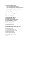
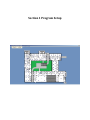
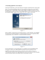
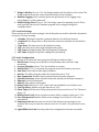
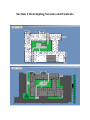
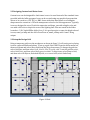
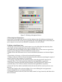
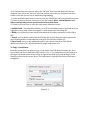
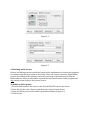
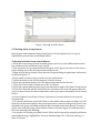
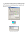
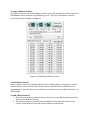
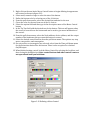
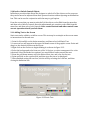
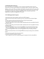
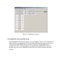
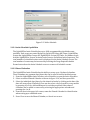
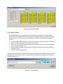
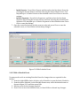
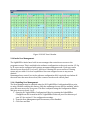
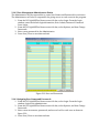
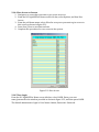
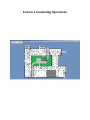
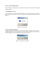
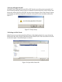
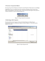
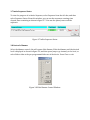
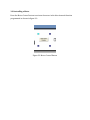
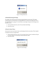
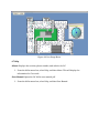
Version 2 6/14 Section 1 Program Setup 1.0 Description 1.1 Minimum Computer Requirements 1.2 Setup Procedure Checklist 1.3 Installing LightLEEDer InSite Software 1.4 Backing up LightLEEDer InSite Data 1.5 Software Configuration Settings 1.5.1 Bridge Configuration 1.5.2 Location Settings 1.5.3 Insite Configuration 1.5.4 Dimmer and Photocell Status Logging 1.6 Starting LightLEEDer InSite 1.7 LightLEEDer InSite Menu Bar Navigation Section 2 Developing Screens and Controls 2.0 Introduction 2.1 Designing Graphical Screens 2.2 Designing Custom Load Status Icons 2.3 Set up the Design Grid 2.4 Develop the Navigation Buttons 2.5 Develop the Load Status Icons 2.6 Defining Presets 2.7 Defining Insite Group Control 2.8 Defining Dimmer Control 2.9 Add Motor Control 2.10 Lock or Unlock Control Objects 2.11 Adding Text to the Screen 2.12 Defining Insite Sequences 2.12.1 Defining an Insite Sequence 2.13 Insite Schedule Setup 2.13.1 Insite Schedule Capabilities 2.13.2 Shared Calendars 2.13.3 Shared Times 2.13.4 Setup a Schedule Event 2.13.5 Edit a Schedule Event 2.13.6 Copy a Schedule Event 2.13.7 Disable Schedule if a Relay is On/Off 2.13.8 Delete an Event 2.13.9 Test an Event 2.13.10 Search for an Event 2.13.11 Full Year View 2.14 Insite User Management 2.14.1 Enabling User Management 2.14.2 User Management Administrator Duties 2.14.3 Assigning User Names and Passwords 2.14.4 User Access to Screens 2.14.5 User Login Section 3 Conducting Operations 3.1 Navigating to a Screen 3.2 Turn a Load ON/OFF 3.3 Sweep All Lights ON/OFF 3.4 Setting an InSite Preset 3.5 Activate a Group Control Button 3.6 Initiating an InSite Sequence 3.7 Insite Sequence Status 3.8 Controlling a Dimmer 3.9 Controlling a Motor Section 4 Additional Options and Tools 4.1 Importing Names 4.2 Opening LightLEEDer Pro 4.3 Manually Starting the Bridge 4.4 Sunrise Sunset Times 4.5 Using the Scroll Feature 4.6 Live usage meters option 4.7 Help Section 1 Program Setup Section 1 Program Setup 1.0 Description 1.1 Minimum Computer Requirements 1.2 Setup Procedure Checklist 1.3 Installing LightLEEDer InSite Software 1.4 Backing up LightLEEDer InSite Data 1.5 Software Configuration Settings 1.5.1 Bridge Configuration 1.5.2 Location Settings 1.5.3 Insite Configuration 1.5.4 Dimmer and Photocell Status Logging 1.6 Starting LightLEEDer InSite 1.7 LightLEEDer InSite Menu Bar Navigation Section 1 Program Setup 1.0 Description ILC LightLEEDer InSite is an object-based GUI (Graphical User Interface) software package that provides a customized interface for the facility lighting control. You can create icons representing a facility’s lighting fixtures, develop control buttons, attach sounds, and design lighting presets for real time control of a building’s lighting loads. You can locate these icons on screens that graphically depict the floor plan of the facility. These screens are Windows compatible bitmap files normally developed at the ILC factory from CAD files furnished by the customer. You can develop your own graphics screens. However, the creation and manipulation of graphic files is an advanced function requiring programs not supplied as part of the InSite software package. Insite also provides an event scheduler and user manager for an all in one package. 1.1 Minimum Computer Requirements The LightLEEDer Insite program requires a dedicated computer(s) for the program to function at its full potential. Typical setups run independent from any internal network in the facility, but are not limited to this. Computers typically are free from antivirus programs and power management that could limit or terminate the program communications. The computer should have the following minimal requirements: IBM compatible PC Core 2 Duo 2.4 GHz Universal Serial Bus port TCP/IP 10/100 Ethernet port Windows 7, 8 32/64 bit 4 GB ram 1.2 Setup Procedure Checklist Install software (section 1.3) Configure software (section 1.5) Design graphical screens (section 2.1) Configure users access (section 2.14) Developing navigation buttons (section 2.4) Develop load status icon buttons (section 2.5) Setup Insite Groups and Presets (section 2.6 and 2.7) Create Insite schedules (section 2.13) Define sequences (section 2.12) 1.3 Installing LightLEEDer Insite Software Connect the thumb drive or place the CD into the computer, and then browse to the storage device. To start the installation, double click the setup file to initiate the process. The file will appear like: ILC LightLEEDer InSite Setup XX BridgeYY ConfigZZ.exe with XX, YY, and ZZ equaling the version of each part of the program. If you receive a security message about this program making changes to your system, click “YES” to approve this action. Figure 1.1 Click on “NEXT” to begin the process as shown in figure 1.1, then “INSTALL”, then “FINISH”. The following screen shown in figure 1.2 will then appear for the driver required for USB communications. Press “INSTALL” to load and finish the installation. Figure 1.2 From the thumb drive or CD provided, there is an updated copy the LightLEEDer Insite user guide: LL_InSite_User_Manual.pdf file that may need to be copied into the ILC LightLEEDer Insite folder located on the root directory of the hard drive. Browse to: C:\Program Files (x86)\ILC\ILC LightLEEDer InSite and create a shortcut of the executable onto your desktop, and into the Startup folder for an automatic startup. 1.4 Backing up LightLEEDer Insite Data It is important that backup copies of all the ILC LightLEEDer InSite data be kept in the event of PC failure. Copy all if the files in the ILC LightLEEDer InSite folder (located on the PC’s hard drive) to the removable media of your choice. Store backups; install discs, screen bitmap files and any documentation in a secure location. 1.5 Software Configuration Settings The configuration file is a file that holds settings that determine how the program will communicate or control the system. Typically this will be configured by the ILC field technician when the system is set up. This must be configured properly for the GUI to communicate to the panels. The ILC LightLEEDer InSite.ini file contains the configuration settings and is located in the ILC LightLEEDer Insite folder on the root directory of the computer’s hard drive. This file must be adjusted using the ILC LightLEEDer Configuration Editor Program located in the ILC LightLEEDer Insite folder, and can be run by executing the LightLEEDer ConfigEdit.exe file. See figure 1.1. The Configuration Editor is made up of 4 sections that include Bridge Configuration, Location settings, Insite Configurations, and Dimmer/Photo Sensor monitoring settings. Figure 1.1 ILC LightLEEDer Configuration Editor 1.5.1 Bridge Configuration The bridge gives the Insite program the ability to communicate with the LightLEEDer lighting control system. These settings set the connection type, communications, and other important bridge settings.. 1. Connection Type: This setting is set for “Single Panel” or “Network System” depending on the hardware installed at the facility. 2. Connection Node: Set to the node number of the single panel the bridge is connected to or to the “Network Controller” for multiple panel systems with a network controller installed. 3. Serial Port: If used, the USB serial port that the PC is communicating through. 4. TCPIP Address: The TCP/IP address of the panel or network controller that the program is communicating through. 5. TCPIP Enabled: Enables the TCP/IP communications through the bridge. 6. Last Used Node: This should be set to the largest node address number used in the lighting control system. 7. Bridge Visibility: If set to “Yes” the bridge window will be visible on the screen. The bridge window shows the connection information for the software. 8. Runtime Logging: If the runtime option was purchased, set for logging relay, relay/dimmer, or relay/photocell. 9. Disable Bridge Close: If set to “Yes” the bridge cannot be manually closed. This is used typically when the ILC Runtime program is also using the bridge for communications. 1.5.2 Location Settings These settings are the location setting for the facility and are used for schedules dependent on sunrise or sunset settings. 1. Latitude: The degree from the equatorial plane for the facilities location. 2. Longitude: The degree East or West from the reference meridian for the facilities location. 3. Time Zone: The time zone for the facilities location. 4. DST: Check the box if observing Daylight Saving Time. 5. DST Starts: Daylight Saving Time starting date (if enabled). 6. DST Ends: Daylight Saving Time ending date (if enabled). 1.5.3 Insite Configuration These settings are for how the Insite program will function and save data. 1. Main Screen: Startup screen (Home screen) Bitmap name. (without .bmp extension) 2. Process Schedules: Select “Yes” for schedules to execute. 3. Disable Edit: If “Yes” is selected, the program cannot be edited by any users. 4. Auto Start: Used only in older legacy software. 5. No Exit: The InSite program cannot be closed when set to “Yes”. 6. Host Connection: Software data location path on the main computer. 7. Schedule Directory: Insite schedule data path. (usually on the main computer) 8. Bitmaps: Screen location path. 9. Objects: Object data location path. 10. Extra Loads: When set to “Yes”, extra loads can be added to a load status icon. 11. Tool Tip Select: Enables tool tips when set to “Yes”. 12. Show Twips: Will show the Twip setting in the Help screen if set to “Yes” Shown in figure 1.2. 13. Disable Host Verify: Forces update in remote InSite computer when set to “Yes”. 14. User Management: Enables advance user manager. See section 2.14 for more information. 15. Unmanaged Access: Sets the access level if the advance user manager is not enabled, and every user has the same access level. See table 1 for password access levels. 16. LightLEEDer Pro Path: Sets the path to the configuration software executable. Table 1 Unmanaged Password Access Levels Figure 1.2 Twips Settings 1.5.4 Dimmer and Photocell Status Logging These setting are used for monitoring dimmer and photo sensor status. The log files are located in the ILC LightLEEDer Insite folder named DimmerStatus.dat and PCLevel.dat. Select the dimmer and/or PC update by selecting the device with the check box. 1.6 Starting LightLEEDer Insite Double click on LightLEEDer Insite icon to start the program. The InSite top level or “Home” screen will appear. The program can be started automatically when the computer boots up by placing a shortcut of the program in the startup file of the operating system. 1.7 LightLEEDer Insite Menu Bar Navigation From the menu bar as shown in figure 1.3 you have the following choices: Home: Navigates you to the top level or Home Insite screen. Back: Returns you to the previous Insite screen. Sweeps: Permits you to sweep ON or OFF all the lighting loads on that screen if this option is enabled. Presets: Lets you develop and activate presets of load status icons which will respond in a pre-determined ON or OFF pattern. Sequence: Allows you to create and initiate a series of events to occur within a 12 hour period, including: Turn ON or OFF a single relay, Turn ON or OFF a LightLEEDer Group, activate a LightLEEDer or InSite presets. Schedule: Opens the Insite Schedule for control of relays, LL Groups, dimmers, LL Presets, Insite Presets, and initiate Sequences. Options: Selectable options for how the program responds. - Verify Sweeps: If selected, you will need to verify that the On or Off sweep is desired prior to executing. -On Sweeps: Allows On sweeps if selected -Off Sweeps: Allows OFF sweeps if selected -Toggle Loads: Lets you directly toggle loads without a separate control window. -Tool Tip Node: Relay: Sets the Tool Tip to show the node and relay number when hovered over the load status icon. -Change Password: Opens the password manager (Only available when enabled). -User Access: Selected to enable/disable screen access (Only available when enabled). -Show Bridge: When selected, the communications bridge will be shown on the screen. Edit: This menu item provides for: – Development of Navigation buttons which allow you to switch between different graphic screens – Adding or copying Load Status icons – Creating Insite Group Control buttons for the control of multiple relay status icons – Adding or copying dimming control icons – Motor Control icon development – Static Text – The locking/unlocking of load status and control buttons – Adjust and apply the grid function – View Large Image allows editing on a PC with lower resolution capabilities Usage: Activates the ILC LightLEEDer Runtime live usage gauge if this option was purchased and installed. Tools: This menu item provides for: – Import LightLEEDer Names – Open LightLEEDer Pro Software – Start Bridge – Show present Sunrise/Sunset Astro settings Quit: Allows you to exit the program Login/Logout: If enabled, it allows the user to login or logout. Help: This provides information on the software revision, and a link to the LightLEEDer Insite User Manual. Figure 1.3 Menu Bar Section 2 Developing Screens and Controls Section 2 Developing Screens and Controls 2.0 Introduction 2.1 Designing Graphical Screens 2.2 Designing Custom Load Status Icons 2.3 Set up the Design Grid 2.4 Develop the Navigation Buttons 2.5 Develop the Load Status Icons 2.6 Defining Presets 2.7 Defining Insite Group Control 2.8 Defining Dimmer Control 2.9 Add Motor Control 2.10 Lock or Unlock Control Objects 2.11 Adding Text to the Screen 2.12 Defining Insite Sequences 2.12.1 Defining an Insite Sequence 2.13 Insite Schedule Setup 2.13.1 Insite Schedule Capabilities 2.13.2 Shared Calendars 2.13.3 Shared Times 2.13.4 Setup a Schedule Event 2.13.5 Edit a Schedule Event 2.13.6 Copy a Schedule Event 2.13.7 Disable Schedule if a Relay is On/Off 2.13.8 Delete an Event 2.13.9 Test an Event 2.13.10 Search for an Event 2.13.11 Full Year View 2.14 Insite User Management 2.14.1 Enabling User Management 2.14.2 User Management Administrator Duties 2.14.3 Assigning User Names and Passwords 2.14.4 User Access to Screens 2.14.5 User Login Section 2 Developing Screens and Controls 2.0 Introduction Before you can actually control building lighting loads using Insite, you must set the stage by designing the graphics screens that represent the facility floor plans and populate these screens with the icons which provide the mechanisms for navigation and control of the building lighting loads. 2.1 Designing Graphical Screens The graphical screens are the backdrops required for the Insite control icons. These screens can be as simple as a single colored background to a high definition depiction of the facility layout. The number of screens is only limited by the capability of storage space on the computer. Screens can be designed using Windows Paint or any other program that can create a Bitmap file format. 1. Create your screen Bitmap to match the resolution setting of your monitor being used. You may desire to use the full resolution or adjust the size to show the task bar. 2. Design a screen with color, logo, layout, and text that can be used as a base Bitmap to keep a consistent look between multiple screens. 3. If AutoCAD files are being used, directly copy the drawing from the CAD program and paste on to the Bitmap screen as a transparent object. Adjust the location and size to fit the screen. 4. The home screen is the opening screen which makes a good navigation point to other screens. 5. Multiple navigation screens can be created to give better resolution to facility areas. 6. Load the screens into the bitmap folder located on the root of your primary hard drive. Example: C:\ILC LightLEEDer InSite\Bitmaps 2.2 Designing Custom Load Status Icons Custom icons can be designed for load status icons to be used instead of the standard icons provided with the InSite program. Icons can be created using any graphical program that allows to be saved as a .GIF, .JPG, or .BMP. Icons with other than square or rectangular shapes must be created as a .GIF with transparent colors for the best appearance. Typically icons are designed in sets of 2 with the same size and shape, one with a bright color and one with a dull color to depict the state of the lighting load. Files are saved in the folder located at: C:\ILC LightLEEDer InSite\Icon_C. It is good practice to name the bright colored icon as; name_on.bmp and the dull colored icon as; name_off.bmp with “name” being unique. 2.3 Setup the Design Grid Using a temporary grid over the workspace as shown in figure 2.1 will assist you in placing icons in a neat and uniform fashion. To set up a grid: Select EDIT from the InSite menu bar, then scroll down and select Show Grid from the drop down menu. To change the grid size, select Grid Size, and then select 8 x 8, 16 x 16, 32 x 32, or 64 x 64. To set the grid line color, select Grid Color, and then select black, gray, or white. To align icons, select Snap to Grid, and then select All Objects, Unlocked Objects, or to revert back, select Undo Snap. Figure 2.1Grid Snap to Grid Hotkeys Ctrl+S = Snap to all locked/unlocked objects Ctrl+U = Snap to all unlocked objects Ctrl+X = Undo snaps 2.4 Develop the Navigation Buttons Navigation buttons allow you to access different graphical screens that have been created. The standard navigation button allows navigating from one screen to another screen. A Global Navigation button appears on all of the available screens. Buttons will need to be added to each screen to give the program flow. To define a navigation button: 1. From the Insite menu bar, point and click on Edit. 2. Point and click on either the Add Navigation Button or Add Global Navigation Button. 3. A new navigation button icon will appear in the upper left hand corner of the graphic screen. Point and drag it to the desired position on the screen. 4. Right click on the navigation button to begin defining it as shown in figure 2.2 5. Point & click on small, normal or large to select the size of the button. 6. Select the button color from one of the 16 choices. 7. From the pull-down menus, select the desired font and size for the text. 8. Select the text color from one of the 16 choices. 9. Point & click on the caption field and then type in the descriptive name of the navigation button. 10. In the screen field, type in the name of the bitmap file you want the button to navigate to (do not add .bmp file extensions). 11. Point & click on the Tip Text field and add the desired text. 12. Point & click on lock check box to lock in the control. Note: control buttons and other control icons are not operational until you lock them. 13. Point & click on close to leave the navigation button definition screen. Figure 2.2 Defining a Navigation Button 2.5 Develop Load Status Icons Load status icons graphically represent facility lighting loads. By defining and placing the load status icons on the screens you can simulate the actual lighting layout of the facility on your computer screen and issue ON/OFF commands to the actual loads. To Define a Load Status Icon: 1. From the screen that you want a load status icon, select Edit from the menu bar, then select Add Load Status, and then New Load. (or Hotkey Ctrl + N). 2. A load status icon will appear in the upper left hand corner of the screen as a green box with an X, point & drag it to the desired position on the screen. 3. Right click on the load status icon to access its definition parameters as shown in figure 2.3. 4. Select Relay, LL Group, or LL Preset from the pull-down menu. - If Relay is selected: Point & click on the node (controller address) containing the output of control, then the relay number to be controlled. - If LL Group is selected, from the pull-down menu; select the desired LL Group to be controlled. Note: The LL Group must be defined in the LightLEEDer controllers. - If LL Preset is selected, from the pull-down menu, select the desired LL Preset to be controlled. Note: The LL Preset must be defined in the LightLEEDer controllers. 6. Select the Tip Text window and add the desired text that will be seen if you hover over the icon. 7. Select the Graphics tab as shown in figure 2.4 to start defining the icon appearance. 8. Select Standard Icons or Custom Icons button. 9. If Standard Icons are selected, select the small, normal, or large icons tab, and then select the icon desired. 10. If Custom Icons are selected, select the “Off Icon” blue box, and then select the predesigned icon. Select the “On Icon” blue box, and the select the pre-designed icon. Once both are selected, press Close to finish the programming. 11. Press Load Information tab to return to the top level of the load icons definition screen. 12. Point & click on the lock check box to lock the control. Note: control buttons and other control icons are not operational until you lock them. 13. Point & click on Close to leave the load status definition screen. • Enable Flood – Selecting this permits you to fill in the backgrounds of enclosed areas on a graphics screen with colors in response to load status icons switching ON. • Blink-you can develop icons which blink when the load they represent is either ON or OFF • Sound- you can define a particular WAV audio file to play when the load it represents goes ON and another sound when the load goes off as shown in figure 2.5. • Extra Loads-Lets you add additional loads to the current relay icon. This allows additional relays to be controlled from this single load status icon. To Copy a Load Status: From the screen that you want to copy a load status icon, Edit from the menu bar, then select Add Load Status, and then Copy Load (or Ctrl + C). A load status icon will appear in the upper left hand corner of the screen as a green box with an X, point & drag it to the desired position on the screen. Note: The load status is copied from the last load status configured. Figure 2.3 Figure 2.4 Figure 2.5 2.6 Defining Insite Presets Presets are lighting patterns you define based on the requirements of a particular situation, for example: special sports event at the facility. There are 2 types of Presets, LightLEEDer presets are resident in the lighting controller(s) and may be invoked directly from the InSite software. InSite presets can be captured and activated from the InSite program and only include status icons on the present screen. To define an InSite preset: 1. Set each load status on the screen to the desired ON/OFF state for the Preset. 2. From the title bar, select Presets, and then select Capture Insite Preset. 3. Name the InSite preset in the window provided as shown in figure 2.6 4. Click on Save. Figure 2.6 Saving an InSite Preset 2.7 Defining Insite Group Control Insite Group control buttons can be developed to control multiple loads, or up to 4 LightLEEDer presets from an individual button. To develop an Insite Group control button: 1. From the screen that you want an Insite group control icon, select Edit from the menu bar, and then select Add Insite Group Control. 2. The new Insite Group control button will appear in the upper left corner of the screen, point and drag it into the desired position on the screen. 3. Right click on the new Insite Group button to begin defining its appearance and control as shown in figure 2.7. 4. Select small, normal or large to select the size of the button. 5. Define the button color by selecting one of the 16 choices. 6. From the pull-down menus, select the desired font and size for the text. 7. Chose the color for the text from one of the 16 choices. 8. Select the caption field and then type in the descriptive name of the Insite Group button. 9. In the Tip Text field, add the desired text for the button. This text will appear when the cursor is hovered over the button and can be used to give more information of the control button. 10. Select Controls Load Status, Activate LL Presets or Activate InSite Preset from the Function field. - For Control Load Status, press Edit Control, select Add Loads as shown in figure 2.8, and then click on the status loads on the screen you want to control in this group. Active icons included in the group will blink to indicate their included in the Insite Group. To remove status icons from the group, select Remove Loads as shown in figure 2.8, and then select the icons until they stop blinking. - For Activate LL Presets, press Edit Control. Select the first preset by using the pull-down menu and selecting a LightLEEDer Preset as shown in figure 2.9. If desired, add up to 3 more LL Presets. - For Activate InSite Preset, press Edit Control. Select the pre-programmed InSite Preset as shown in figure 2.10, and then Open. 11. When finished setting control, lock the Group control by selecting the Lock box, and then closing the definition box. Note: control buttons and other control icons are not operational until you lock them. Figure 2.7 Group Control Figure 2.8 Select Loads Figure 2.9 Select LightLEEDer Presets Figure 2.10 Select InSite Presets 2.8 Defining Dimmer Control Controls can be setup for controlling LightSync dimmer devices from the InSite screen. This control has a slide controller that allows the end user to jump or fade to a percentage of dimming. It also has the ability to display current diming state. Note: Dimmers controlled by a photo sensor or slide switch cannot be controlled through InSite. Note: Dimmer Status Updates must be enabled in the software configurations setting. To add a new Dimmer Control: 1. From the screen that you want a dimmer control, select Edit from the menu bar, then select Add Dimmer Status, and then New Dimmer(or Ctrl + A). 2. A dimmer control icon will appear in the upper left hand corner of the screen as a green box with an X, point & drag it to the desired position on the screen. 3. Right click on the new Dimmer Control Icon to begin defining its appearance and control as shown in figure 2.11. 4. Select the Display State check box if status only is desired, or select Change Icons and select a slider from the large icons. 5. From the pull-down menus, select the Node address, device address, and the output number of the hardware that you want this button to control. 6. For the Tip Text, you can select the check box provided to have the dimmer level appear, or add the desired text for the button. This status or text will appear when the cursor is hovered over the button and can be used to give more information of the control. 7. Status only can be accomplished by selecting No Control. 8. Additional dimmer outputs can be added to the dimmer control by selecting the check boxes for the outputs desired. Select the Node address, and then select the desired outputs. Additional outputs can be cleared in all nodes by selecting the “Clear Additional” button. 9. When finished setting the control, lock the Dimmer Control by selecting the Lock box, and then closing the definition box. Note: control buttons and other control icons are not operational until you lock them. To Copy a Dimmer Control: From the screen that you want a dimmer control, select Edit from the menu bar, then select Add Dimmer Status, and then Copy Dimmer (or Ctrl + D). Note: The dimmer control is copied from the last dimmer configured. Figure 2.11 Defining a Dimmer Control 2.9 Add Motor Control InSite is able to control the LightSync Motor Control Module which is designed to control window shades, louvers, doors, and other DC motor controlled devices. Buttons can be programmed to drive the motor in one direction or another for a selectable time from .1 to 300 seconds. To add a Motor Control: 1. From the screen that you want a motor control icon, select Edit from the menu bar, then select Add Motor Control. 2. The new Insite Motor Control button will appear in the upper left corner of the screen, point and drag it into the desired position on the screen. 3. Right click on the new Insite Motor Control button to begin defining its appearance and control as shown in figure 2.12. 4. Select small, normal or large to select the size of the button. 5. Define the button color by selecting one of the 16 choices. 6. From the pull-down menus, select the desired font and size for the text. 7. Chose the color for the text from one of the 16 choices. 8. Select the caption field and then type in the descriptive name of the Motor Control button. 9. In the Tip Text field, add the desired text for the button. This test will appear when the cursor is hovered over the button and can be used to give more information of the control. 10. From the pull-down menus, select the Node address, device address, and the output number of the hardware that you want this button to control. 11. Select the desired control function from the pull-down menu. The options are; stop motor, run positive, and run negative. 12. If a run positive or run negative are selected, select from the Time pull-down menu for the action time desired for this button. There is also an option for a latched On/Off output. 13. When finished setting control, lock the Motor Control by selecting the Lock box, and then closing the definition box. Note: control buttons and other control icons are not operational until you lock them. Figure 2.12 Defining a Motor Control 2.10 Lock or Unlock Control Objects InSite has a provision that allows the designer to unlock all of the objects on the screen so they can be moved or adjusted from their present location without opening each definition box. This can be used in conjunction with the snap to grid option. From the screen that you want to unlock all of the objects, select Edit from the menu bar, and then select Unlock Controls. Once the adjustments are complete, select Edit from the menu bar, and then select Lock Controls. Note: control buttons and other control icons are not operational until you lock them. 2.11 Adding Text to the Screen Static text can be added to an InSite screen. This text may be as simple as the screen name to instructions for the end user. 1. Point & click on Edit on the Insite menu bar, and then select Add Static Text. 2. A new text box will appear in the upper left hand corner of the graphic screen. Point and drag it to the desired position on the screen. 3. Right click on the text box to begin defining it as shown in figure 2.13. 4. Select the background color from one of the 16 choices, or select transparent if no color is desired. Select the Border box option if you would like a border around the text. 5. From the pull-down menus, select the desired font, size, and color for the text. 6. Point and click on the caption field, and then type the text to be displayed. 7. When finished setting the text box, lock the text by selecting the Lock box, and then closing the definition box. Figure 2.13 Static Text 2.12 Defining Insite Sequences Insite Sequences give you capability to create control in sequential order for up to 16 actions over a 12 hour period. Sequences are typically used for events that require timed lighting control events. There is no limit to the number of sequences that can be set up. The 16 sequences actions can be initiated at 5 minute intervals and consist of; turn Off a single relay, turn On a single relay, activate a LightLEEDer Preset, activate a Insite Preset, LightLEEDer Group Off, and LightLEEDer Group On. 2.12.1 Defining an Insite Sequence 1. From the title bar select Sequence, and the select Edit Sequence. 2. Select the first unused control, and then select the control desired as shown in figure 2.14. 3. Set the sequence action start time that will react from the time initiated. 4. Set the type of control action for this sequence. - Turn Off a single relay, select the node number, and then select the relay number from the pull-down menu. - Turn On a single relay, select the node number, and then select the relay number from the pull-down menu. - Turn Off a LightLEEDer Group, select the LightLEEDer Group from the pull-down menu. - Turn On a LightLEEDer Group, select the LightLEEDer Group from the pull-down menu. - To activate a LightLEEDer Preset, select the LightLEEDer Preset from the pull-down menu. - To activate an Insite Preset, select the LightLEEDer Preset by browsing to the saved Insite Preset. 5. Select the next unused action, time and control. 6. Continue to build the sequences desired. 7. Once completed, select Save As, and then name the sequence for the event and Save. Figure 2.14 Defining a Sequence 2.13 LightLEEDer Insite Schedule Setup The LightLEEDer Insite has the ability to control loads on a time or astro schedule. The Insite schedule runs independently from the LightLEEDer panel timers but the Insite schedules and LightLEEDer timers can operate together. If LightLEEDer Insite schedules are used, to avoid problems, it is suggested that LightLEEDer timers be avoided, and vice versa, if LightLEEDer timers are used, Insite schedules should be avoided. Figure 2.15 InSite Schedule 2.13.1 Insite Schedule Capabilities The LightLEEDer Insite Schedule has up to 4000 programmable scheduled events available. Each event can control Relays On, Relays Off, Relays Off/Timer, LightLEEDer Groups On, LightLEEDer Groups Off, LightLEEDer Groups Off/Timer, Set dimmer levels, Activate LightLEEDer Presets, Activate Insite Presets, and initiate Insite Sequences. The total number of scheduled events used is displayed on the Insite Schedule screen. The total number of events may be increased by selecting the Purge Expired Schedule Events button from the Insite Schedule screen to remove old schedule events. 2.13.2 Shared Calendars The LightLEEDer Insite Schedule has the ability to setup up to 16 shared calendars. These calendars are common days/dates that can be used to build scheduled events. 1. From the LightLEEDer Insite title bar, select Schedule to open the Insite Scheduler. 2. Select an unused Shared Calendar as shown in figure 2.16, and then press Edit. 3. Select the individual days/dates for this shared calendar by clicking on the date (the date will turn yellow if included). You can also select a day-of-week for every month by pressing A or R for Add and Remove for each day required. Other shared calendars can be added or removed by selecting the appropriate calendar and pressing the A or R. 4. From the box in the upper left corner, name the Shared Calendar for identification when setting up a scheduled event. 5. Press Close to save the Shared Calendar, or Cancel not to save. Figure 2.16 Shared Calendar 2.13.3 Shared Times The LightLEEDer Insite Schedule has the capability to setup up to 16 shared times. These times are common times that can be used to build scheduled events. They might be facility open or closed time, or a time that is used often when building Schedule Events. 1. From the LightLEEDer Insite title bar, select Schedule to open the Insite Scheduler. 2. Select an unused Shared Times, and then press Edit. 3. Click U or D for Up and Down to adjust the hour and minute settings for this shared time as shown in figure 2.17. 4. From the box provided, name the Shared Time for identification when setting up a scheduled event. 5. Close to save the Shared Time. Note: InSite Schedule Shared Times can be set to the original default name if desired. Select the shared time desired to return to the default name. From that window, select Default Name and then Close. Figure 2.17 Shared Time 2.13.4 Setup a Schedule Event 1. From the LightLEEDer Insite title bar, select Schedule to open the Insite Scheduler. 2. Select the New button from Schedule Events. See Sections 2.12.5 and 2.12.6 for information on editing and copying. 3. From the Edit Schedule Event screen, enter a name for this event in the box provided in the upper left hand corner of the screen. 4. Select a calendar from the pull-down menu. - Custom Calendar: From the Calendar pull-down menu select Custom Calendar. Click on the individual dates (active dates will be colored yellow) or add the days of the week by pressing A or R to add or remove. Shared calendar dates can be added or removed by selecting the calendar from the pull-down menu, and then pressing A or R to add or remove the dates pre-configured. Note: These shared calendar dates added or removed are the present configuration of the shared calendars and does not change if the shared calendar changes. - Shared Calendar: From the Calendar pull-down menu select the shared calendar desired. The days will be highlighted in blue and cannot be changed unless the shared calendar is changed. Note: If the Shared Calendar is changed, it will be automatically changed for this event. 5. Select the time for this scheduled event. - For a Fixed Time, click on U or D for Up and Down to adjust the hour and minute settings for this schedule event. - For a Shared Time, select the Shared Time from the pull-down menu. This time cannot be changed unless the shared time is changed. - For an Astro Time, select the time at, before, or after Sunrise/Sunset. Note: The location settings must be configured properly using the Insite Configuration Editor for the Astro schedules to work correctly. 6. Set the control action for this schedule event. From the selections shown below select 1 or more actions for this event; - Relays: –Select Turn On, Turn Off, or Blink/Off. Press, Select Relays, and then select the node address from the pull-down menu. Click on the relays to include from this node, and then if required, select another node and relays until all of the desired relays are added. Press Close to save the settings. - LightLEEDer Groups: - Select Turn On, Turn Off, or Blink/Off. Press, Select Groups, and then select the Groups to be controlled by this schedule event Press Close to save the settings. - Dimmers: Press Select Dimmers, and then select the node address from the pulldown menu where the dimmer(s) outputs reside. Click on the dimmers outputs to include from this node and set the dimming level percentage value, and then if required, select and set dimmers output values for other nodes in the system. Press Close to save the settings. - LightLEEDer Presets: - Press Select Presets, and then select the Presets to be controlled by this schedule event. Press Close to save the settings. Insite Presets: - Press Select Presets, and then select the first Insite Preset by pressing the browse button, and then selecting the desired Insite Preset. You may add up to 16 Insite Presets to this schedule event. Press Close to save the settings. - Initiate Sequence - Press Select Sequences, and then select the first Insite Sequence by pressing the browse button, and then selecting the desired Insite Sequence. You may add up to 16 Insite Sequences to this schedule event. Press Close to save the settings. 7. Once the controlled actions for this event are selected, press Close to save the schedule event, or Cancel Edits to discard any changes. - Figure 2.18 Edit Schedule Event 2.13.5 Edit a Schedule Event You may need to edit an existing Schedule Event for changes that are required for the facility. 1. From the LightLEEDer Insite title bar, select Schedule to open the Insite Scheduler. 2. From the Insite Schedule, in the Schedule Events area, select the desired event as shown in figure 2.18, and then press Edit. 3. Edit the event for the changes required. 4. Press Close to save the schedule event, or Cancel Edits to discard any changes. 2.13.6 Copy a Schedule Event You may copy an existing Schedule Event and adjust for a new event. 1. From the LightLEEDer Insite title bar, select Schedule to open the Insite Scheduler. 2. From the Insite Schedule, in the Schedule Events area, select a previously configured event, and then press Copy. 3. Edit the event as required. 4. From the Edit Schedule Event screen, enter a name for this event in the box provided upper left hand corner of the screen. 5. Press Close to save the schedule event, or Cancel Edits to discard any changes. 2.13.7 Disable Schedule if Relay is On/Off Schedule Events can be disabled from activating by monitoring a relays in On or Off state. 1. From the LightLEEDer Insite title bar, select Schedule to open the Insite Scheduler. 2. From the Insite Schedule, in the Schedule Events area, select a previously configured event that you want to be disabled by a relay. 3. From the Schedule Event, select the Disable Schedule Item; - Never: This is the default setting for the event and is not disabled by a relay. - If Relay On: If the selected relay is On, the schedule event will not activate. - If Relay Off: If the selected relay is Off, the schedule event will not activate 4. From the pull-down menus, select the node address and relay to monitor. 5. Press Close to save the schedule event, or Cancel Edits to discard any changes. 2.13.8 Delete an Event Events that are unwanted can be deleted from the database. 1. From the LightLEEDer Insite title bar, select Schedule to open the Insite Scheduler. 2. From the Insite Schedule, in the Schedule Events area, select the Event to be deleted, and then press Edit. 3. Press the Delete This Event button to remove. 2.13.9 Test an Event Events that have been programmed can be tested to verify the operation. 1. From the LightLEEDer Insite title bar, select Schedule to open the Insite Scheduler. 2. From the Insite Schedule, in the Schedule Events area, select the Event to be tested, and then press Edit. 3. Press the Test This Event button to initiate this event. 2.13.10 Searching for Events The LightLEEDer Insite Schedule has a search feature that can search through the schedule events for certain relays, LightLEEDer Groups, Dimmers, LightLEEDer Presets, Insite Presets, or Sequences. 1. From the LightLEEDer Insite title bar, select Schedule to open the Insite Scheduler. 2. From the Search area, select a category to search. 3. Adjust the field for the control type and number. You will need to browse to the file to search for Insite Presets and Sequences. 4. Press the Search button to scan data base. 5. From the pull-down menu you will see the events that have the control item related to this search. 6. Select an event, and then press “Edit This Schedule Event” to make adjustments or view the event. 7. Press Close when done. 2.13.11 Full Year View The LightLEEDer Insite Schedule has a full year calendar; it displays how many events are scheduled for a particular date. From this calendar you can directly edit any of the Schedule Events for that date. 1. From the LightLEEDer Insite title bar, select Schedule to open the Insite Scheduler. 2. From the Insite Schedule screen, select Full Year View. 3. From the calendar as shown in figure 2.19, select the date desired to view. This will open the events overview for the date. Note: The total number of events associated to the date will be displayed for each calendar day. 4. If the event needs to be viewed or edited, select the event from the pull-down menu and press Edit This Schedule Event. 5. Press Close to exit. Figure 2.19 Full Year Calendar 2.14 Insite User Management The LightLEEDer Insite has a built-in user manager that controls user access to the programs screens. This is enabled in the software configuration as shown in section 1.5. Up to 32 users can be configured with unique usernames and passwords. Each user can be allowed access from level 1 to level 5, with level 1 having full access and level 5 having status only see table 1 for level capabilities. Users are assigned access to any screen desired. Unmanaged user control (set in the software configuration file) is typically used when all the users have the same access level, like a remote touch screen control panel. 2.14.1 Enabling User Management The User Manager must be enabled using the ILC LightLEEDer Configuration Editor prior to using. Without enabling this feature, only the unmanaged access will be available, which gives the same access for every user. This also is adjusted using the Configuration Editor and gives access to levels 1 to 5. 1. Open the ILC LightLEEDer Configuration Editor by running the LightLEEDer ConfigEdit.exe file located in the ILC LightLEEDer folder on your root directory of your PC. See section 1.5 for configuration settings. 2. From the User Management pull-down menu, select Enabled. 3. Click Save and Exit 2.14.2 User Management Administrator Duties The Administrator will be responsible to create User Names and Passwords for each user. The Administrator will also be responsible for giving access to each screen in the program. 1. From the ILC LightLEEDer Home screen title bar, select Login. From the Login window, enter the default login information; User: Admin, Password: Password. Press Login. 2. From the ILC LightLEEDer Home screen title bar, select Options, and then Change Passwords. 3. Enter a new password for the Administrator. 4. Press Save/Close to save data and exit. Figure 2.10 User and Passwords 2.14.3 Assigning User Names and Passwords 1. From the ILC LightLEEDer Home screen title bar, select Login. From the Login window, login as the administrator. 2. From the ILC LightLEEDer Home screen title bar, select Options, and then Change Passwords. 3. Enter a new user names, passwords, and access level for each user as shown in figure 2.20. 4. Press Save/Close to save data and exit. 2.14.4 User Access to Screens 1. Navigate to a screen that you want to give a user access to. 2. From the ILC LightLEEDer Home screen title bar, select Options, and then User Access. 3. From the pull-down menu, select Allow for every user you want to give access to this screen as shown in figure 2.21. 4. Press Save/Close to save data and exit. 5. Complete this procedure for ever screen in the system. Figure 2.21 User Access 2.14.5 User Login From the ILC LightLEEDer Home screen title bar, select LOGIN. Enter your user name/password in the window provided as shown in figure 2.22, and then press LOGIN. The default administrator login is: User Name= Admin, Password= Password. Figure 2.22 Login Window Section 3 Conducting Operations Section 3 Conducting Operations 3.1 Navigating to a Screen 3.2 Turn a Load ON/OFF 3.3 Sweep All Lights ON/OFF 3.4 Setting an InSite Preset 3.5 Activate a Group Control Button 3.6 Initiating an InSite Sequence 3.7 Insite Sequence Status 3.8 Controlling a Dimmer 3.9 Controlling a Motor Section 3 Conducting Operations Once the InSite is programmed it is very intuitive to navigate and control the facilities lights with the software. 3.1 Navigating to a Screen From the Home screen, select the navigation button for the screen desired. If you have been given access, the screen will open, if not, you will get an Access Denied window as shown in figure 3.1 Figure 3.1 Access denied 3.2 Turn a Load Status ON/OFF To toggle a load status, click on the icon desired. If the Toggle Load option is activated, the load(s) will toggle state. If the Toggle Load option is inactive, a Load Status box will open as shown in figure 3.2, select the desired action, and then press Close. Figure 3.2 Load Status Control Box 3.3 Sweep All Lights ON/OFF All of the status loads can be turned ON or OFF for the screen that you are presently at if the ON Sweeps and OFF Sweeps option is enabled. From the menu bar, select Sweeps, and then select either ALL ON or ALL OFF for the action to happen. If the Verify Sweeps option is activated, you will be prompted to verify the action prior to the execution as shown in figure 3.3. Figure 3.3 Verify Sweep 3.4 Setting an InSite Preset InSite Presets are pre-determined On/Off state of the lighting loads of a screen. From the InSite menu bar, select Presets, and then Activate InSite Preset. Select the InSite Preset file as shown in figure 3.4 and then Open to activate. Figure 3.4 Open InSite Preset file 3.5 Activate a Group Control Button Press the Group Control button to activate the control function. If the button is controlling a LightLEEDer Preset or an InSite Preset the activation will happen. If the Group Control button is programmed to load status, then a Group Control box will appear with options to Turn On, Turn Off, or Cancel as shown in figure 3.5 Figure 3.5 Group Control for load status 3.6 Initiating an InSite Sequence From the title bar select Sequence, then select Initiate Sequence. Select the preprogrammed sequence, and then press Open as shown in figure 3.6. This will start the sequence of events. Figure 3.6 Open Sequence file 3.7 Insite Sequence Status To view the progress of an Insite Sequence, select Sequence from the title bar, and then select Sequence Status. From this window, you can see the sequences running, time elapsed, time remaining as shown in figure 3.7. You can also pause/run or end the sequence. Figure 3.7 InSite Sequence Status 3.8 Control a Dimmer Select the dimmer control; this will open a slide dimmer. Slide the dimmer until the desired level is displayed as shown in figure 3.8, and then press Jump to go instantly to the level, or select Fade to dim at the pre-programmed fade rate of the device. Press Close to exit. Figure 3.8 Slide Dimmer Control Window 3.9 Controlling a Motor Press the Motor Control button to activate the motor in the direction and duration programmed as shown in figure 3.9. Figure 3.9 Motor Control Button Section 4 Additional Options and Tools Section 4 Additional Options and Tools 4.1 Importing Names 4.2 Opening LightLEEDer Pro 4.3 Manually Starting the Bridge 4.4 Sunrise Sunset Times 4.5 Using the Pan Feature 4.6 Live usage meters option 4.7 Help 4.1 Importing Names The InSite program has the ability to import names from the LightLEEDer configuration software. They include names for Relays, LightLEEDer Groups, and LightLEEDer Presets. 1. Export the names from the ILC LightLEEDer Single Panel Configuration Software or the ILC LightLEEDer Network Configuration Software. This file was created in the C:\ILC LightLEEDer or C:\ILC LightLEEDer Net folder and will have the same name as the programming file with a .NAM extension. 2. From the InSite menu bar, select Tools, and then Import Names. 3. Browse out to the file exported, and then Open. 4.2 Opening LightLEEDer Pro The ILC LightLEEDer Single Panel Configuration Software or the ILC LightLEEDer Network Configuration Software can be executed directly from the InSite program. The software will automatically stop the bridge for the InSite program and start the configuration software. 1. From the InSite menu bar, select Tools, and then Open LightLEEDer Pro. 2. Program the lighting panels as desired with the LightLEEDer Pro software, and then download to the panels. 3. Close the LightLEEDer Pro program. 4. The bridge will automatically start and display a message as shown in figure 4.1 Figure 4.1 Bridge Restarted 4.3 Manually Starting the Bridge The bridge is the link between the software and the lighting control panels. The bridge normally starts up automatically, but if LightLEEDer Pro is opened, the bridge will close. If the LightLEEDer Pro is going to be used without connecting to the panels, the bridge can be manually started. 1. From the InSite menu bar, select Tools, and then Start Bridge. 2. Press OK to close. 4.4 Sunrise Sunset Times Astronomical sunrise and sunset times can be displayed for the current day. This is helpful if scheduled events are programmed. 1. From the InSite menu bar, select Tools, and then Sunrise Sunset. A window will open as shown in figure 4.2 with today’s sunrise and sunset times. 2. Press OK to close. Figure 4.2 Astro Settings 4.5 Using the Pan Feature InSite has the capability to design screen controls on a computer with lower screen resolution than the screen used at the facility. This feature is used for designing screens, and not designed to be used on the control computer at the facility. This feature gives you the ability to pan the larger screen up, down, left, and right. When enabled, a pan button will appear in the upper left hand corner of the screen as shown in figure 4.3. 1. From the InSite menu bar, select Edit, and then select View Large Image. 2. Click on the desired pan direction to move the screen. Figure 4.3 Panning Button 4.6 Live Usage Meters Option Live usage meters displays the current usage of the lighting loads for the area programmed into the software. This option is available to be used in conjunction with the InSite program. This option is available when the Basic Runtime Monitoring has been purchased and installed on the InSite computer. From 1 to 4 meters can be displayed as shown in figure 4,4. 1. From the InSite menu bar, select Usage. 2. With the left mouse button, drag the window to the desired location on the screen. 3. Select Dials, then the number of meters to be displayed. Figure 4.4 Live Usage Meter 4.7 Help -About: Displays the revision, phone number, and website for ILC 1. From the InSite menu bar, select Help, and then About. This will display the information for 5 seconds. -User Manual: Opens the ILC InSite user manual pdf. 1. From the InSite menu bar, select Help, and then User Manual. Intelligent Lighting Controls, Inc. Minneapolis, MN 55439 www.ilc-usa.com