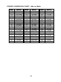
1
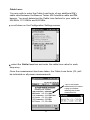
WS Technologies Inc. Beacon Tester Operator‟s Manual for models: BT100A BT100S BT100AVtriple BT100AVS including all Ruggedized (-R) models Version 3.11 Information contained in this manual is subject to change without notice. Please consult the website at www.wst.ca for new Operator’s Manual updates. Complying with all applicable copyright laws is the responsibility of the user. Without limiting the rights under copyright, no part of this document may be reproduced, stored in a retrieval system, or transmitted in any form or by any means including but not limited to, electronic, mechanical, photocopying, recording, or otherwise, or for any purpose, without the written permission of WS Technologies Inc. (WST). WST may have patents, patent applications, trademarks, copyrights, or other intellectual property rights covering subject matter in this document. Except as expressly provided in any written license agreement from WST, the furnishing of this document does not give you any license to these patents, trademarks, copyrights, or other intellectual property. The purchaser shall not in any event be entitled to, and WST shall not be liable for indirect, special, incidental or consequential damages of any nature including, without limitation, business interruption costs, loss of profit or revenue, loss of data, promotional or manufacturing expenses, overhead, injury to reputation or loss of customers, even if WST has been advised of the possibility of such damages. In any event, purchaser's recovery from WST for any claim shall not exceed purchaser's purchase price for the product giving rise to such claim irrespective of the nature of the claim, whether in contract, tort, warranty, or otherwise. WST shall not be liable for and purchaser shall indemnify, defend and hold WST, its agents, distributors, dealers, successors and assigns harmless from any and all claims, damages or losses, including injury or death, arising from or relating to the use or failure of the products. Copyright © 2012 WS Technologies Inc. All rights reserved. Printed in Canada April 2012 ii CONTENTS INTRODUCTION............................................................................................................... 1 SUMMARY OF MODELS .................................................................................................. 1 UNPACKING ..................................................................................................................... 1 BEFORE YOU START ...................................................................................................... 2 GETTING STARTED......................................................................................................... 2 Flowcharts: ................................................................................................................... 2 Setting the desired measurement File Name:................................................................ 6 Setting the Input Mode and REF Mode: ........................................................................ 6 Selecting the desired 10 MHz Reference source: .......................................................... 7 Selecting the desired RF Input Mode: ........................................................................... 7 Setting the Configuration Settings: ................................................................................ 8 Saving Options Setting:................................................................................................. 9 Location Coordinates Setting: ....................................................................................... 9 Receive Mode Settings: ................................................................................................ 9 Non- 406 MHz Beacons: ............................................................................................... 9 PDA Display Options Settings: .................................................................................... 10 Stability Settings: ........................................................................................................ 10 Cable Loss: ................................................................................................................. 11 MAKING MEASUREMENTS ........................................................................................... 12 General: ...................................................................................................................... 12 Conventional Measurement Mode:.............................................................................. 14 Stability Measurement Mode (BT100S and BT100AVS models only): ......................... 15 Terminating the Stability Test Prior to Completion: ...................................................... 17 MEASUREMENTS RESULTS ......................................................................................... 18 Decode Screens: ........................................................................................................ 18 Details Screens: .......................................................................................................... 19 Graphics screens: ....................................................................................................... 19 Options: ...................................................................................................................... 20 User Comments: ......................................................................................................... 20 Listen to 121/243 Audio (BT100AVtriple and BT100AVS models only): ....................... 21 Morse Code Decipher (BT100AVtriple and BT100AVS models only): ......................... 21 Files: ........................................................................................................................... 22 About Beacon Tester: ................................................................................................. 23 121.5 MHz Homing Transmitter in Self-Test Mode: ..................................................... 23 PRINTING THE MEASUREMENT TEST REPORT ......................................................... 24 ActiveSyncTM: .............................................................................................................. 24 Memory Card: ............................................................................................................. 25 Wireless Link: ............................................................................................................. 27 DELIMITED TEXT FILE................................................................................................... 28 RE-INSTALLING OR UPDATING BEACON TESTER SOFTWARE ................................ 28 SOFTWARE UPDATES .................................................................................................. 29 BEACON TESTER MODEL UPGRADING ...................................................................... 29 RUGGED PDA CONSIDERATIONS ............................................................................... 29 USING THE TSE100 SCREEN BOX ............................................................................... 29 LIMIT TESTER SOFTWARE ADD-ON ............................................................................ 32 FREQUENTLY ASKED QUESTIONS ............................................................................. 33 SPECIFICATIONS .......................................................................................................... 36 REGULATORY INFORMATION ...................................................................................... 37 DECLARATION OF CONFORMITY ................................................................................ 38 WARRANTY INFORMATION .......................................................................................... 39 CALIBRATION ................................................................................................................ 39 RETURNS....................................................................................................................... 39 POWER CONVERSION CHART - dBm to Watts ............................................................ 40 iii WARNING! DO NOT ACTIVATE ANY BEACON IN ITS NORMAL ACTIVATE MODE UNLESS THE BEACON IS IN A SCREEN BOX (TSE100) OR A SCREEN ROOM. DOING SO COULD RESULT IN A FALSE DISTRESS ALERT. WARNING! WHEN USING 5 WATT INPUT MODE DO NOT EXCEED A DUTY CYCLE OF ONE BURST (520 MS) EVERY 30 SECONDS. DAMAGE WILL RESULT! iv INTRODUCTION Thank you for choosing the BT100 series of 406 Beacon Testers. This Operator’s Manual explains the operation of all available models: BT100A, BT100S, BT100AVtriple, and BT100AVS, and all Ruggedized (-R) models. Measurement capabilities differ with each model. SUMMARY OF MODELS BT100A: This model decodes the 406 MHz message, measures the 406 MHz transmitter and the 121.5 MHz transmitter. BT100S: This model decodes the 406 MHz message, measures the 406 MHz transmitter, the 406 MHz frequency stability, and the 121.5 MHz transmitter. BT100AVtriple: This model decodes the 406 MHz message, measures the 406 MHz transmitter, the 121.5 MHz transmitter, and the 243 MHz transmitter (if present). BT100AVS: This model decodes the 406 MHz message, measures the 406 MHz transmitter, the 406 MHz frequency stability, the 121.5 MHz transmitter, and the 243 MHz transmitter (if present). -R: When any of the above models include a –R suffix, that model is equipped with a ruggedized PDA. UNPACKING Please verify the contents of your package. It should contain: Beacon Tester CF Card Operator’s Manual Certificate of Calibration with Calibration data 406 Interface cable REF Interface cable Screen cleaning cloth Zipper Pouch (not included with –R models) Waterproof yellow hard case PDA CD containing PDA software AC Adapter PC interface cable PDA User Manual 1 BEFORE YOU START Unpack the PDA and charge the batteries in accordance with the PDA manufacturer’s instructions. TM NOTE: ActiveSync must be installed on any computer that you TM wish to connect the PDA. Install ActiveSync on your desktop computer using the PDA CD or, for the most up-to-date version, TM download ActiveSync from the Microsoft website. Please refer to the PDA documentation for instructions. NOTE: In the event that the Beacon Tester application is lost due to PDA battery discharge, re-installation is very simple. Refer to Re-Installing or Updating the Beacon Tester Software section for details. GETTING STARTED Please read this Operator’s Manual to become familiar with the operation of the Beacon Tester. Flowcharts: Examining the Navigation Flowcharts located on the following pages will help you understand the basic operation of the Beacon Tester program. 2 3 Rename Open Select All Delete Files Screen Help Files Options View STABILITY RECEIVE Start Screen View loaded file About Beacon Tester Files Listen to 121/ 243 Audio User Comments Set Print and Configuration Options Select 10 MHz Reference Frequency and RF Input Source Options Screens Display Ongoing results Stability Test Screen Cancel Progress bar "Waiting for burst" Screen To Start Screen To Decode Screens Decode 121/243 Details Screen To Decode Screens Decode 406 Spectrum Screen Next Decode Screen #n To Options Screens Options Next 406 Phase Screen To Options Screens Options Next Stability Screen To Options Screens Options Graphics Screens To Details Screens Details 406 Power Screen To Graphics Screens Graphics 406 Details Screen To Graphics Screens Graphics Decode Screen #2 Details Screens To Details Screens Details Decode Screen #1 Decode Screens Beacon Tester Flowchart (Availability of some functions depends on model. Beacon Tester Graphic Flowchart 4 Running the Beacon Tester Application: Ensure the Beacon Tester CF card is inserted into the CompactFlash (CF) slot of the PDA. Launch the Beacon Tester application by tapping: Start > Programs > Beacon Tester Start Programs Beacon Tester 5 The 406 Beacon Tester title screen will show for a few seconds followed by the Receive screen: OK button Input button REF button File Name button Options button Setting the desired measurement File Name: tap the File Name button as shown above. type the desired measurement file name followed by OK. type the desired number extension followed by OK. NOTE: Do not use forbidden file name characters: / \ : * ? “ < > | Setting the Input Mode and REF Mode: tap either the Input button or REF button as shown above. The following screen will appear. 6 Selecting the desired 10 MHz Reference source: select Internal to use the internal 10 MHz reference frequency. select External to use an external 10 MHz reference frequency. NOTE: For Stability mode measurements, the external 10 MHz -10 reference stability must be better than 1 x 10 . The internal 10 MHz reference is not suitable for completing Stability measurements. In non-Stability mode measurements, the external -9 10 MHz reference stability must be better than 1 x 10 . Selecting the desired RF Input Mode: select Internal Antenna when receiving the beacon signal through the air. select External Coax when receiving the beacon signal using a 50Ω coax cable via an indirect method such as a directional coupler or a screen box with a sniffer antenna and 50 ouput. select 5 Watt Input when connecting the output of the beacon directly to the RF Input using the 406 Interface cable. Use this mode when using the WST Screen Box (model TSE100) with the beacon and the tester connected directly and both located in the Screen Box. tap OK (top right corner) when done. WARNING! WHEN USING 5 WATT INPUT DO NOT EXCEED A DUTY CYCLE OF ONE BURST (520 MS) EVERY 30 SECONDS FOR A 406 MHz 5 WATT SIGNAL. DAMAGE WILL RESULT! NOTE: Using the 5 Watt Input will result in absolute power measurement units (dBm). Using the Internal Antenna or External Coax will result in relative power measurement units (%). 7 Setting the Configuration Settings: tap the Options button. tap the Printing/Configuration Options button. Organization field button Tested By field button tap the Organization field as shown above. enter your organization name or initials. tap the Tested By field as shown above. enter your name or initials as desired. 8 NOTE: The entered Organization and Tested By names will appear on each printed Test Report. Saving Options Setting: select the Save HTML to SD card box if you want each measurement saved to an SD memory card in addition to being saved in the standard PDA memory. Not available in the Ruggedized models. Location Coordinates Setting: select the box relating to your desired location coordinate display. NOTE: dd° mm.mm‟ is degrees/decimal minutes, dd° mm‟ ss” is degrees/minutes/seconds. Receive Mode Settings: to receive each burst manually (i.e.: you have to press Receive for each measurement), do not select any box. if you are measuring a beacon in the activate mode where the beacon is transmitting a burst each 50 seconds, then select the Continuous Receive box. when using Continuous Receive mode, you have the option of saving each burst or saving only the last burst. Select the desired box. NOTE: When saving each burst, the number on the end of the File Name will automatically increment. Non- 406 MHz Beacons: if you are measuring a beacon without 406 MHz capabilities, then select one of the following: Receive 121/243 MHz only box. Receive 121 MHz only box. Receive 243 MHz only box. NOTE: In the 121/243 MHz only mode, the modulation measurements are derived from the 121 MHz transmitter. 9 HTML (Test Report) Print Settings: scroll down on the Configuration Settings screen. NOTE: You can choose the level of detail you wish to print on the Test Report. if you do not wish to print the detailed 406 Measurements then unselect the Detailed 406 Measurements box. The frequency and power will still be printed. if you do not wish to print the detailed 121/243 Measurements then un-select the Detailed 121/243 Measurements box. The frequency and power will still be printed. if you do not wish to print the 406 MHz Graphics then un-select the Display 406 Print Graphics box. PDA Display Options Settings: if you do not wish to see the detailed measurements or graphics on the PDA display then un-select the Show Detailed Measurements box or Show Graphics box as appropriate. NOTE: The Detailed Measurements and/or Graphics can be displayed later by re-selecting the appropriate box. Stability Settings: select the desired setting to display either parts per billion (ppb) or scientific notation. select the desired delimiter (comma or semicolon) to use in the delimited text file that is generated during Stability tests. 10 Cable Loss: You may wish to enter the Cable Loss factor of any additional 50 cable used between the Beacon Tester 406 Interface cable and the beacon. You must determine the Cable Loss factors for your cable at 406 MHz, 121.5 MHz and 243 MHz. scroll down on the Configuration Settings screen. select the Cable Loss box and enter the cable loss value for each frequency. Once the measurement has been taken, the Cable Loss factor (CL) will be indicated on all power measurements. Tap on the power measurement to show a pop-up window detailing the power measurement: 11 MAKING MEASUREMENTS NOTE: Interpreting the results provided by the Beacon Tester requires some knowledge of beacon requirements. Using the self test mode of the beacon may result in some measurements being outside the required limits due to the lack of a warm-up period. WARNING! DO NOT ACTIVATE ANY BEACON IN ITS NORMAL ACTIVATE MODE UNLESS THE BEACON IS IN A SCREEN BOX (TSE100) OR A SCREEN ROOM. DOING SO COULD RESULT IN A FALSE DISTRESS ALERT. General: All measurements will produce a Test Report. In addition, the stability models (BT100S and BT100AVS) will create a delimited text file. Measurement results are stored in the PDA memory. Each measurement will be saved in a folder with the same name as the measurement. For example, a measurement with the name “Burst-1” is made on a beacon. When the measurement is completed, the following is created: <Burst-1> Burst-1.htm graphics_enabler.class folder name test report utility file The next measurement will be named “Burst-2” unless manually changed. When the Receive Mode Settings are set to Continuous Receive and Save each burst, then each burst measurement will be saved in the same folder: <Burst-1> Burst-1.htm Burst-2.htm Burst-3.htm Burst-4.htm etc. graphics_enabler.class 12 folder name st 1 burst test report nd 2 burst test report rd 3 burst test report th 4 burst test report utility file For the stability models (BT100S and BT100AVS) in the Stability mode, the measurement will be saved in a folder with the same name as the measurement. For example, a stability measurement with the name “Burst-5” is made on a beacon. When the measurement is completed, the following is created: <Burst-5> Burst-5.htm graphics_enabler.class Burst-5(S).txt 13 folder name test report utility file delimited text file Conventional Measurement Mode: tap the Receive button. Receive button Stability button The following screen will appear and the timer will start. activate the beacon under test. if the beacon is transmitting a 121.5/243 MHz homing signal the tester will produce the characteristic swept audio tone and display 121/243 Received. once a 406 MHz burst is received, the first Decode screen automatically appears. See the MEASUREMENT RESULTS section. 14 Stability Measurement Mode (BT100S and BT100AVS models only): from the Receive screen tap the Stability button. The following screen will appear. tap here to select Test Duration Select the desired duration of the test by tapping on the area to the right of Test Duration. This value can be between 1 minute and 43,200 minutes (30 days). NOTE: Cospas-Sarsat requirements allow a 15 minute warm-up period before starting the stability test. You can turn the beacon ON and allow it to warm-up for 15 minutes before starting the test, in which case the first stability data point (after 18 bursts) must be within specification. Alternatively, you can turn the beacon on and start the test simultaneously, in which case the beacon does not have to be in specification until 15 minutes after the first stability data point. start the test by tapping the Start Test button. 15 After the first burst, the following screen will appear: In the measurement folder on the PDA, a delimited text file is created. This text file is updated after each burst during the stability measurement test. This delimited text file can be imported to your favourite spreadsheet or database application. th On the 18 burst the stability values are calculated and displayed in the appropriate fields. After each burst, the screen is updated with new values, along with the delimited text file. Once Test Duration has been reached, one final burst is automatically captured to create the Test Report. 16 NOTE: The background of the 15 HEX ID field will turn green when a GPS location is reported in the 406 message. Terminating the Stability Test Prior to Completion: If you wish to stop the stability test prior to the Test Duration, then tap Stop. The Stop button will turn into a Cancel button. The display will show “waiting for final burst ...”. In order to create a Test Report this final burst must be captured. Once the final burst is captured the test is complete and both the Test Report and delimited text file will reside in the measurement folder. If the final burst is not available (i.e.: the beacon battery has failed) then press the Cancel button. No Test Report will be created, however, the delimited text file is still available containing all of the measured stability information. 17 MEASUREMENTS RESULTS NOTE: Only the stability models (BT100S and BT100AVS) will show the measurement results for the Frequency Stability Platform. Decode Screens: tap the Next button to cycle through the Decode screens. Next button Details button 18 Graphics button Details Screens: tap the Details button to access the Details section. tap the Next button to cycle through the Details screens. NOTE: the Frequency Stability Platform screen will only appear when the Stability Measurement mode is used in the stability models (BT100S and BT100AVS). Graphics screens: tap the Graphics button to access the Graphics section. tap the Next button to cycle through the Graphics screens. 19 Options: pressing the Options button from any of the measurement modes will bring you to this screen: User Comments: Once a measurement has been made, you can add user comments. These comments will be saved to the measurement file. Adding Text Comments: from the Options screen, tap User Comments > Text Comment. type the desired text comment and tap OK. The text comment will appear on the printed Test Report. Adding Audio Comments: from the Options screen, tap User Comments > Audio Comment. tap Record and speak clearly into the PDA microphone. When finished, tap Stop and tap OK. The audio comment will be saved with the measurement file and can be replayed when opening the measurement file at a later time. 20 Listen to 121/243 Audio (BT100AVtriple and BT100AVS models only): To listen to the real-time demodulated audio tap either the Listen to 121 button or the Listen to 243 button. Tap Stop to stop the real-time audio decoding. Morse Code Decipher (BT100AVtriple and BT100AVS models only): If Morse Code is present on the 121 or 243 MHz signal then check the Enable Morse Code box. The deciphered Morse Code will be displayed. 21 Files: tap Files from the Options screen. Tapping a file name will select the file name. Tapping the file name again will de-select it. Pressing Select All will select all of the files. The Open and Rename buttons will only work when a single file name has been selected. To delete multiple files, tap Select All or select each file individually, then press Delete. NOTE: The PDA can store many measurements. It is strongly advised to transfer your measurements to a storage card or a PC. TM The PDA is a Windows device and subject to periodic situations where data may be lost. 22 About Beacon Tester: tap About Beacon Tester from the Options screen. This screen displays information about the Beacon Tester card installed in the PDA, along with the Firmware and Software dates and versions. The Calibration Due date is shown. A real-time temperature sensor displays the temperature inside the Beacon Tester. 121.5 MHz Homing Transmitter in Self-Test Mode: When measuring a beacon using the self-test mode, results for the 121.5 MHz transmitters may vary between different beacon manufacturers. In the self-test mode, some beacons transmit about 1 second of modulated carrier, some beacons transmit a short duration of unmodulated carrier, while some beacons do not transmit 121.5 MHz at all. If the length of modulated carrier is too short for the Beacon Tester to measure, or if a short duration of unmodulated carrier is transmitted, then the Beacon Tester will display the message “unable to measure details” or “unmodulated carrier”. 23 PRINTING THE MEASUREMENT TEST REPORT Each measurement generates a folder containing an HTML file containing the measurement data. To generate a printed Test Report, the measurement folder must be transferred to a directory on the PC that is connected to a printer. The transfer of the folder can be TM accomplished via ActiveSync , memory card (Secure Digital or CompactFlash), or wireless link. TM ActiveSync : TM connect the PDA to the PC using the ActiveSync cable in accordance to the PDA manufacturer’s instructions. TM depending on your Windows version, go to My Computer or Explorer on the PC and double-click on: Mobile Device. Mobile Device 24 The resulting window will display the PDA file system. go to the Measurements directory by clicking on: My Windows Mobile-Based Device > Beacon Tester > Measurements Each stored measurement will have a folder with the measurement name. Using standard Windows techniques, Cut and Paste, or Drag and Drop the desired measurement folder to the Desktop or any desired location on the PC. From the PC directory where you transferred this measurement folder, open the folder. Double-clicking on the measurement html file will open it in your browser. Once open, select File > Print and the measurement Test Report will be printed. Memory Card: In order to transfer files using a memory card, you will need a memory card reader on your PC. This can be internal or external. The memory card can be either a CompactFlash (CF) card or a Secure Digital (SD) card. NOTE: The memory card slot is not accessible on the Ruggedized models. 25 turn the PDA on and tap Start > Programs. tap File Explorer. File Explorer go to the Measurements directory by tapping Beacon Tester > Measurements. Each measurement will have a folder. tap and hold on the measurement folder that you want to transfer. select Copy navigate back to the My Device directory by tapping the PDA icon (located below the Windows logo in the top left corner) and tapping My Device. 26 tap on the desired memory card, SD Card or CF Card. tap Edit (located in the lower left corner) and tap Paste. The measurement folder should now be on the memory card. remove the memory card from the PDA slot and insert it into the card reader attached to the PC. the card reader will appear as another drive on your PC. Open this drive. Using standard Windows techniques, Cut and Paste, or Drag and Drop the desired measurement folder to the Desktop or any desired location on the PC. from the PC directory where you transferred this measurement folder, open the folder. Double-clicking on the measurement html file will open it in your browser. Once open, select File > Print and the measurement Test Report will be printed. Wireless Link: if your PDA is equipped with wireless capabilities set up according to the manufacturer’s instructions. go to File Explorer on the PDA by tapping Start > Programs > File Explorer. go to the Measurements directory by tapping Beacon Tester > Measurements. Each completed measurement will have a folder. tap and hold on the measurement folder that you want to transfer. select Copy navigate to the desired folder on the PC and tap and hold until the selection menu appears. Select Paste. from the PC directory where you transferred this measurement folder, open the folder. Double-clicking on the measurement html file will open it in your browser. Once open, select File > Print and the measurement Test Report will be printed. NOTE: A copy of the graphics_enabler.class file must be present in the folder in order for the measurement graphics to be printed on the Test Report. 27 DELIMITED TEXT FILE In the stability models (BT100S and BT100AVS), the Stability mode produces a (comma or semicolon) delimited text file containing details on the stability measurement. To access this file, connect the PDA to the PC. From the PC navigate to Mobile Device > Beacon Tester > Measurement > “measurement folder name”. In this delimited file, each burst creates a record containing the following fields: Date/Time, Burst #, UIN, Full HEX, 406 Power, S1, S2, S3, Elapsed Time, Nominal Frequency, Short Term Stability, Medium Term Stability Mean Slope, and Medium Term Stability Residual Frequency. Each field is terminated with a carriage return linefeed (CRLF). This file can be used in whatever application the user requires to analyze or graph the results. RE-INSTALLING OR UPDATING BEACON TESTER SOFTWARE Some levels of reset on various PDA models will cause the Beacon Tester program to be deleted from the program memory. It can easily be re-installed. On the PDA navigate to Built-In Storage directory. tap Start > Programs > File Explorer. navigate to My Device and tap Built-In Storage. open the BTInstaller folder and tap on the BTInstaller program. NOTE: If the BTInstaller folder or file are missing then go to www.wst.ca and download and install the latest Beacon Tester Software version. Follow the instructions on the website. Follow the instructions on the screen. DO NOT interrupt the installation. Be patient as the installation may take one or two minutes to complete. A green bar at the bottom of the screen will indicate when installation is complete. If the CF Card is not removed during installation then a soft PDA reset must be initiated to complete the installation process. For the nonrugged PDAs, press the PDA Reset button. For the Rugged PDA, press and hold the Power button for 5 seconds to initiate the reset process. 28 Rugged PDA only: Hold Power button for 5 seconds to initiate reset SOFTWARE UPDATES Software updates are available free of charge on the WS Technologies Inc. website: www.wst.ca You are encouraged to keep your Beacon Tester software up to date by downloading and installing the most current software revision. Follow the installation instructions on the website. BEACON TESTER MODEL UPGRADING All models can be remotely upgraded as desired. Please contact your purchasing distributor or WS Technologies Inc. for upgrade costs and procedures. RUGGED PDA CONSIDERATIONS Removing CF Card in Rugged version: If you need to replace the CF Card follow these steps: Using the screwdriver end of the stylus, rotate the 2 locking screws on the top cap to the unlock position. Locking screws in unlock position 29 Gently, pull top cap away from PDA body, then grasp CF Card and pull out of CF slot. Disconnect RF cable from CF card by gently pulling blue cable directly out of CF card connector. Inserting CF Card in Rugged version: Connect blue RF cable to CF card connector. Place CF card into CF slot in PDA. Ensure it is properly seated (PDA will turn on). Ensure top cap locking screws are rotated to the unlock position. Tuck blue cable into top end of cap, then install top cap onto PDA body ensuring the cable is not pinched. Using the screwdriver end of the stylus, rotate locking screws to the lock position. Stability Mode Measurements using Rugged version: The top cap must be removed when doing stability measurements in order to connect the required stable 10MHz reference signal. Using the screwdriver end of the stylus, rotate the 2 locking screws on the top cap to the unlock position. Gently, pull top cap away from PDA body, then grasp CF Card and pull out of CF slot. Disconnect RF cable from CF card by gently pulling the blue cable directly out of CF card connector. Connect the REF Cable (p/n 130-008) to the REF Input on the CF Card. Connect the RF cable (p/n 130-019) to the 406 Input on the CF Card. (If you are using a direct connection between the Beacon-under-test and the Tester.) 30 Insert the CF Card into the CF slot in the PDA. Cable p/n 130-008 connect to 10MHz Reference signal Cable p/n 130-019 connect to Beacon-under-test USING THE TSE100 SCREEN BOX The TSE100 Screen Box will allow testing of the beacon in normal activate mode without the risk of being detected by a satellite (causing a false alert). If the beacon being tested has an internal GPS receiver, the TSE100 will allow you to verify the GPS reception and ensure proper encoding of location data onto the 406 MHz transmission. Both the beacon and the Beacon Tester are placed into the TSE100 Screen Box. The viewing window and the screened gloves allow you to control both the beacon and the Beacon Tester. 31 LIMIT TESTER SOFTWARE ADD-ON The LTS100 LimitTester software add-on is integrated within the BT100 software that will allow the user to determine if a beacon has passed or failed – on the fly. When a beacon fails, the user is notified immediately which parameters have failed and by how much. A separate Test Report is generated showing all of the passed and failed measurement values. The user can select the individual parameters that are tested or not tested. Visit www.wst.ca for more details. 32 FREQUENTLY ASKED QUESTIONS I am trying to use my Beacon Tester but I get a „type mismatch‟ error message. Perform a Clean reset on your PDA (refer to page 12 of the iPAQ manual). This will take the PDA to the out-of-box state, so you will need to re-install the Beacon Tester software from the website www.wst.ca Follow the download and installation instructions on the website. I haven‟t used my Beacon Tester for a while. Now, I can‟t find the Beacon Tester icon. The Beacon Tester software will need to be re-installed. Tap Start > Programs > File Explorer > My Device > Built-in Storage > BTInstaller > BTInstaller.exe. Follow the procedure in the section entitled RE-INSTALLING BEACON TESTER SOFTWARE. The procedure is very simple. If the BTInstaller folder is missing then go to the website www.wst.ca and download the latest Software. Why is my PDA not responding? Occasionally the PDA will go into a mode where it will not respond to any input. Doing a soft reset by pressing the RESET button on the PDA usually fixes this problem. Refer to the PDA manual. Why does nothing happen when I launch the Beacon Tester program? Occasionally the Beacon Tester application does not terminate properly. Try tapping Start > Settings > System > Memory > Running Programs > Stop All. Then try to re-launch the program. Why can‟t I see the graphics on my Test Report? Each measurement folder contains a copy of the file named graphics_enabler.class that is required for the graphics to be displayed on the Test Report. Make sure a copy of this file is present in the same folder as the measurement HTML file. My Beacon Tester won‟t receive either 406 MHz or 121.5 MHz. Ensure that the proper Input mode is selected. If you are receiving a beacon self test transmission through its antenna, then select Internal Antenna. If you are testing a beacon in a screen box and connecting via the coax cable, then select External Coax. If you are connected directly to the ELT then select 5 Watt. 33 My GPS coordinates are being displayed in degrees/decimal minutes (dd° mm.mm‟). I prefer degrees/minutes/seconds (dd° mm‟ ss”). How do I change this? Tap Options > Printing/Configuration Options. Select the desired format under the GPS Coordinates heading. The internal temperature sensor appears to be reading high. Is there a problem? Due to normal internal heating of the components, it is perfectly normal for the temperature sensor to indicate a reading that is a few degrees higher than the ambient temperature. How many measurements will the PDA store? The PDA can hold over 1000 measurements. If you have a 5 second comment on each measurement, then the PDA can hold about 200 measurements. It is strongly advised to transfer your measurements to a storage card (CompactFlash or Secure Digital) or to a PC for long term storage. How do I change a file name? Select Options > Files. Select the file that you wish to change. Tap Rename. From the pop-up keyboard enter the desired new file name and tap OK. How do I update the Beacon Tester software? Go to the WS Technologies Inc. website at www.wst.ca and follow the instructions on updating the application software. When I updated the Beacon Tester software I now have two Beacon Tester icons on the Program screen. How do I remove the second icon? The second Beacon Tester icon can be easily removed by tapping Start > Programs > File Explorer > My Device > Windows > Start Menu > Programs. Tap and Hold on one of the Beacon Tester icons. When the pop-up menu appears, select delete. When I activate the beacon in self test mode, the measurements produce questionable results. Is there a problem with the beacon? In order to meet all of the Cospas-Sarsat requirements, a beacon is allowed a 15 minute warm-up period. When testing a beacon in self test, there is no warm-up period, hence some measurements may be somewhat skewed. 34 Also, in self-test, the 121.5 homing transmission may be different depending on the particular beacon. Some beacons transmit a short modulated signal, some beacons transmit a shorter unmodulated signal and some beacons transmit no signal. The Beacon Tester may indicate “unable to measure details” or “unmodulated carrier” depending on the beacon characteristics. I am testing an ELT with separate 121.5 and 406 output connectors. What do I do to get the results printed on one Test Report? Connect to the 121.5 transmitter first, then start the test. Once the Beacon Tester gives the indication that the 121.5 signal has been received, switch the cable to the 406 transmitter without stopping the test. Once the 406 burst is received on the Beacon Tester, the measurement will be complete. I have a BT100AVS model. How do I import the stability measurement delimited text file into Microsoft Excel? From Excel, click File > Open. From the pop-up window under Files of Type select Text Files (*.prn, *.txt, *.csv). Go to the directory where your measurement file is saved. Click on the desired text file and click Open. The Text Import wizard will be displayed. Under the Original data type section select delimited. Click Next. In the next window under the Delimiters section select Comma or Semicolon (depending on which delimiter you have selected on the Beacon Tester). Click Finish. To size the columns, select all columns then Format > Column > AutoFit Selection. The data is now available to easily graph or analyze the data as desired. Is the characteristic swept tone audio that I hear when the Beacon Tester receives a 121.5 MHz signal the actual demodulated audio from the beacon? No, the swept tone audio is just an audio file played when the tester has received a 121 MHz signal. On the BT100AVtriple and BT100AVS models the actual 121/243 demodulated audio can be heard using the Listen to 121/243 Audio buttons in the Options menu. 35 SPECIFICATIONS BT100AVS BT100AVtriple ELT Testers BT100AV series ACCURACY 100 Hz 0.4 ppm/year 1 Hz Frequency * Stability 406 MHz MEASUREMENTS Measure all Cospas-Sarsat Frequency Channels Decode all Cospas-Sarsat Protocols UIN & Full HEX Frequency (using INT REF) (resolution = 100 Hz) Leaving Factory Long Term Frequency (using EXT REF) (resolution = 1 Hz) Nominal Frequency Short Term Medium Term - Mean Slope Medium Term - Residual Power Power Rise Time Phase Modulation Modulation Rise and Fall Times Modulation Symmetry Modulation Bit Rate CW Preamble BT100S PARAMETER BT100A Beacon Testers BT100 series 121.5 MHz/243 MHz MEASUREMENTS 121.5 MHz Frequency (using INT REF) (resolution = 100 Hz) Leaving Factory Long Term 243 MHz Frequency (using INT REF) (resolution = 100 Hz) Leaving Factory Long Term 121. 5 MHz Frequency (using EXT REF) (resolution = 1 Hz) 243 MHz Frequency (using EXT REF) (resolution = 1 Hz) 121.5 MHz Peak Power 243 MHz Peak Power Sweep Direction Audio Frequency Sweep Range Duty Cycle Modulation Factor Sweep Repetition Rate Listen to Real-Time 121.5 Audio Listen to Real-Time 243 Audio Decipher Morse Code * User must supply a stable 10 MHz Reference Signal 36 2.5 x 10⁻¹¹ 1 dB 0.5 ms 0.04 rad 10 μs 0.005 0.2 bps 0.8 ms 100 Hz 0.4 ppm/year 100 Hz 0.4 ppm/year 30 Hz 30 Hz 1.5 dB 1.5 dB 30 Hz 60 Hz 2% 5% 0.1 Hz Miscellaneous Range (using Internal Antenna): 406 MHz 121.5 MHz RF Input VSWR RF Input Level: 406 MHz Burst 121.5 MHz 10 MHz REF Input VSWR 10 MHz REF Input Level Operating Temperature Range Storage Temperature Range Internal Temperature Sensor Accuracy RF Input Cable Termination 10 MHz REF Cable Termination Dimensions: BT100 w x l x h mm (inches) BT100 in PDA w x l x h mm (inches) Hard Case w x l x h mm (inches) >10 m >3 m 1.10:1 -13 dBm Min +40 dBm Max -28 dBm Min +31 dBm Max 1.15:1 -10 dBm Min +10 dBm Max 0°C to +50°C -20°C to +60°C 0.5°C BNC-female SMA-female 43.5 (1.71) x 58.5 (2.30) x 12.7 (0.50) 73 (2.87) x 140 (5.50) x 16.5 (0.65) 324 (12.75) x 273 (10.75) x 114 (4.50) REGULATORY INFORMATION CANADA This Class B digital apparatus complies with Canadian ICES-003. USA Note: This equipment has been tested and found to comply with the limits for a Class B digital device, pursuant to part 15 of the FCC Rules. These limits are designed to provide reasonable protection against harmful interference in a residential installation. This equipment generates, uses and can radiate radio frequency energy and, if not installed and used in accordance with the instructions, may cause harmful interference to radio communications. However, there is no guarantee that interference will not occur in a particular installation. If this equipment does cause harmful interference to radio or television reception, which can be determined by turning the equipment off and on, the user is encouraged to try to correct the interference by one or more of the following measures: Reorient or relocate the receiving antenna. Increase the separation between the equipment and receiver. Connect the equipment into an outlet on a circuit different from that to which the receiver is connected. Consult the dealer or an experienced radio/TV technician for help. This equipment complies with Part 15 of the FCC Rules. Operation is subject to the following two conditions: 1. This equipment may not cause harmful interference. 2. This equipment must accept any interference that may cause undesired operation. 37 EUROPEAN UNION DECLARATION OF CONFORMITY Supplier Name: WS Technologies Inc. Supplier Address: #2 – 215 Neave Road Kelowna, B.C. Canada V1V 2L9 Declares under our sole responsibility that the following product Product Name: 406 Beacon Tester Model BT100 Conforms to the following normative European and International Standards Normative Standards: EN 300 220-1 V1.3.1 (2000-09) EN 301 489-3 V1.4.1 (2002-04) EN 61000-4-2 :1995 EN 61000-4-3 :1996 Following the provisions of the normative European Council 1999/5/EC R&TTE Directive. Product conformance to cited product specifications is based on sample (type) testing, evaluation, or assessment at Nemko Canada, Inc. located in Ottawa, Canada. Accepted by EU or FCC Notified and Competent Bodies. Supplementary Information: This product was tested and complies with all the requirements for the CE Mark. W.A.Street President WS Technologies Inc. #2 – 215 Neave Road Kelowna, BC Canada V1Y 5L9 Phone: (250) 765-7583 FAX: (250) 765-1652 38 WARRANTY INFORMATION WS Technologies Inc. (WST) warrants the products manufactured by WST to be free from defects in material and workmanship for one year from the date of shipment. This warranty is NOT inclusive of the PDA nor its accessories. All PDA and PDA accessories are covered under the PDA manufacturer’s warranty. The purchaser is required to contact the PDA manufacturer for these warranty issues. Liability of WST under the foregoing warranty is limited to the replacement or repair, at the option of WST, of any products which show defective workmanship or materials within one year from the date of shipment, which replacement shall be made FOB WST's facility in Kelowna, BC, CANADA, upon proof satisfactory to WST of the defect claimed. Except for the foregoing warranty, WST makes no other warranty, express or implied, as to the merchantability or fitness for a particular purpose of products shipped or the performance thereof, and does not make any warranty to the purchaser's customers or agents. CALIBRATION The BT100 series of Beacon Testers has been designed to have a standard two year calibration cycle. The calibration date appears on the Calibration Certificate supplied with the Beacon Tester and the Cal Due date appears on the back of the Beacon Tester CF Card. Before returning a unit for calibration, email [email protected] to obtain an RMA (Return Materials Authorization) number and shipping instructions. For all models except the Ruggedized (-R) models, return only the BT100 CF Card – do not return the PDA. Once calibrated a new Cal Due date label will be placed on the back of the CF Card and a new Calibration Certificate will be issued. For Ruggedized models return the complete unit. RETURNS An RMA (Return Materials Authorization) number must be obtained by emailing [email protected] . If the unit being returned is not covered under warranty, a minimum repair charge will apply. If damage is severe or the products have been tampered with, there may be additional charges. 39 POWER CONVERSION CHART - dBm to Watts dBm -12 -11 -10 -9 -8 -7 -6 -5 -4 -3 -2 -1 0 1 2 3 4 5 6 7 Watts 0.06 mW 0.08 mW 0.10 mW 0.13 mW 0.16 mW 0.20 mW 0.25 mW 0.32 mW 0.40 mW 0.50 mW 0.63 mW 0.8 mW 1.0 mW 1.3 mW 1.6 mW 2.0 mW 2.5 mW 3.2 mW 4 mW 5 mW dBm 8 9 10 11 12 13 14 15 16 17 18 19 20 21 22 23 24 25 26 27 Watts 6 mW 8 mW 10 mW 13 mW 16 mW 20 mW 25 mW 32 mW 40 mW 50 mW 63 mW 79 mW 100 mW 126 mW 158 mW 200 mW 250 mW 316 mW 398 mW 500 mW 40 dBm 28 29 30 31 32 33 34 35 36 37 38 39 40 41 42 43 44 45 46 47 Watts 630 mW 800 mW 1.0 W 1.3 W 1.6 W 2.0 W 2.5 W 3.2 W 4.0 W 5.0 W 6.3 W 8.0 W 10 W 13 W 16 W 20 W 25 W 32 W 40 W 50 W