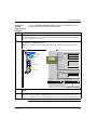
1
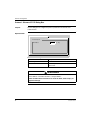
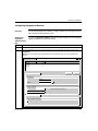
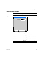
Telemecanique
Siemens PPI Protocol
XBT N/R
33003992.00
09/2007
www.telemecanique.com
2
Table of Contents
Safety Information . . . . . . . . . . . . . . . . . . . . . . . . . . . . . . . . . . . . 5
About the Book . . . . . . . . . . . . . . . . . . . . . . . . . . . . . . . . . . . . . . . 7
Chapter 1
Operating Principle. . . . . . . . . . . . . . . . . . . . . . . . . . . . . . . . . . . . 9
At a Glance . . . . . . . . . . . . . . . . . . . . . . . . . . . . . . . . . . . . . . . . . . . . . . . . . . . . . . 9
General Information on Bus Communications. . . . . . . . . . . . . . . . . . . . . . . . . . . 10
Operating Principle . . . . . . . . . . . . . . . . . . . . . . . . . . . . . . . . . . . . . . . . . . . . . . . 11
Chapter 2
Software Configuration . . . . . . . . . . . . . . . . . . . . . . . . . . . . . . . 13
At a Glance . . . . . . . . . . . . . . . . . . . . . . . . . . . . . . . . . . . . . . . . . . . . . . . . . . . . .
Vijeo-Designer Lite . . . . . . . . . . . . . . . . . . . . . . . . . . . . . . . . . . . . . . . . . . . . . . .
Protocol - Siemens S7 PPI Dialog Box . . . . . . . . . . . . . . . . . . . . . . . . . . . . . . . .
Configuring Equipment Addresses . . . . . . . . . . . . . . . . . . . . . . . . . . . . . . . . . . .
Equipment Address Dialog Box. . . . . . . . . . . . . . . . . . . . . . . . . . . . . . . . . . . . . .
Chapter 3
13
14
16
17
19
Variable Types Supported . . . . . . . . . . . . . . . . . . . . . . . . . . . . . 21
Variable Types Supported. . . . . . . . . . . . . . . . . . . . . . . . . . . . . . . . . . . . . . . . . . 21
Chapter 4
Cables and Connectors . . . . . . . . . . . . . . . . . . . . . . . . . . . . . . . 23
At a Glance . . . . . . . . . . . . . . . . . . . . . . . . . . . . . . . . . . . . . . . . . . . . . . . . . . . . . 23
Cables . . . . . . . . . . . . . . . . . . . . . . . . . . . . . . . . . . . . . . . . . . . . . . . . . . . . . . . . . 24
SUB-D25 Pin Connections . . . . . . . . . . . . . . . . . . . . . . . . . . . . . . . . . . . . . . . . . 25
Chapter 5
Diagnostics . . . . . . . . . . . . . . . . . . . . . . . . . . . . . . . . . . . . . . . . . 27
XBT Error Indication . . . . . . . . . . . . . . . . . . . . . . . . . . . . . . . . . . . . . . . . . . . . . . 27
3
Appendices
. . . . . . . . . . . . . . . . . . . . . . . . . . . . . . . . . . . . . . . . . . . . . . . 31
At a Glance . . . . . . . . . . . . . . . . . . . . . . . . . . . . . . . . . . . . . . . . . . . . . . . . . . . . . 31
Appendix A
RS485 Recommendations. . . . . . . . . . . . . . . . . . . . . . . . . . . . . 33
RS485 Recommendations . . . . . . . . . . . . . . . . . . . . . . . . . . . . . . . . . . . . . . . . . . 33
4
Glossary
. . . . . . . . . . . . . . . . . . . . . . . . . . . . . . . . . . . . . . . . . . . . . . . 35
Index
. . . . . . . . . . . . . . . . . . . . . . . . . . . . . . . . . . . . . . . . . . . . . . . 37
Safety Information
§
Important Information
NOTICE
Read these instructions carefully, and look at the equipment to become familiar with
the device before trying to install, operate, or maintain it. The following special
messages may appear throughout this documentation or on the equipment to warn
of potential hazards or to call attention to information that clarifies or simplifies a
procedure.
The addition of this symbol to a Danger or Warning safety label indicates
that an electrical hazard exists, which will result in personal injury if the
instructions are not followed.
This is the safety alert symbol. It is used to alert you to potential personal
injury hazards. Obey all safety messages that follow this symbol to avoid
possible injury or death.
DANGER
DANGER indicates an imminently hazardous situation, which, if not avoided, will
result in death or serious injury.
WARNING
WARNING indicates a potentially hazardous situation, which, if not avoided, can result
in death, serious injury, or equipment damage.
CAUTION
CAUTION indicates a potentially hazardous situation, which, if not avoided, can result
in injury or equipment damage.
33003992 09/2007
5
Safety Information
PLEASE NOTE
Electrical equipment should be installed, operated, serviced, and maintained only by
qualified personnel. No responsibility is assumed by Schneider Electric for any
consequences arising out of the use of this material.
© 2007 Schneider Electric. All Rights Reserved.
6
33003992 09/2007
About the Book
At a Glance
Document Scope
This document describes the connection to and the communication with the
Siemens PPI protocol for the XBT N/R product range.
Validity Note
The data and illustrations found in this document are not binding. We reserve the
right to modify our products in line with our policy of continuous product
development. The information in this document is subject to change without notice
and should not be construed as a commitment by Schneider Electric.
Related
Documents
33003992 09/2007
Title of Documentation
Reference Number
XBT N/R/RT Instruction sheet
W916810140111 A07
XBT N/R/RT User Manual
33003962
Vijeo-Designer Lite
Online help
7
About the Book
Product Related
Warnings
Schneider Electric assumes no responsibility for any errors that may appear in this
document. If you have any suggestions for improvement or amendments or have
found errors in this publication, please notify us.
No part of this document may be reproduced in any form or by means, electronic or
mechanical, including photocopying, without express written permission of
Schneider Electric.
All pertinent state, regional and local safety regulations must be observed when
installing and using this product. For reasons of safety and to ensure compliance
with documented system data, only the manufacturer should perform repairs to
components.
Since the XBT N/R terminals are not designed to pilot safety critical processes, no
specific instructions apply in this context.
User Comments
8
We welcome your comments about this document. You can reach us by e-mail at
[email protected]
33003992 09/2007
Operating Principle
1
At a Glance
Overview
This chapter describes the operating principle of XBT terminals in applications using
the Siemens PPI protocol.
What's in this
Chapter?
This chapter contains the following topics:
33003992 09/2007
Topic
Page
General Information on Bus Communications
10
Operating Principle
11
9
Operating Principle
General Information on Bus Communications
Overview
The XBT terminals can be connected to PLCs using different protocols. This
document describes the communication using the Siemens PPI protocol with the
XBT terminal acting as client.
Tasks of XBT
Terminals
The terminals are usually connected to a communication equipment (PLC or other)
via a field bus. The XBT and the PLCs work autonomously of each other.
XBT terminals perform the following functions:
z monitoring function: XBT terminals visualize the processes that are active in the
PLCs and indicate alarm states
z command function: XBT terminals send information to the PLC upon user request
Tasks of Buses
A bus system provides the possibility to connect different devices via a unique
cabling.
Tasks of
Protocols
The protocol defines the language that is spoken by all the equipment connected to
the bus.
10
33003992 09/2007
Operating Principle
Operating Principle
Overview
The PPI protocol is one of the console link protocols for Siemens Simatic S7 and
S7-S200.
This protocol is compatible with XBT N/R terminals.
Communications between a process controller's (or a computer's) processor and
the XBT terminal using the PPI protocol are performed by exchanging messages in
the directions point-to-point by means of an asynchronous serial link coupler.
The dialog between the higher processing levels and the XBT terminal is of the
question/reply type. The requester (client station) transmits the messages to be
executed to the server.
Note: The maximum number of bytes for an exchange is 218 (109 words). With the
PPI protocol, the terminal communicates in RTU (Remote Terminal Unit) mode.
Example: operation with an XBT N401
Question
Reply
Client
Server
The XBT has the status of client.
WARNING
UNINTENDEND EQUIPMENT OPERATION
The protocol must be installed and used by authorized and properly trained
peronnel.
Failure to follow these instructions can result in death, serious injury, or
equipment damage.
33003992 09/2007
11
Operating Principle
A server’s memory zone is accessed by means of the server’s address.
Example: operation with an XBT N401
Server 1
Server 2
S7-200
Client
12
33003992 09/2007
Software Configuration
2
At a Glance
Overview
This chapter contains the protocol parameters you must configure in the
Vijeo-Designer Lite software for operating XBT terminals in Siemens PPI protocol
applications.
What's in this
Chapter?
This chapter contains the following topics:
33003992 09/2007
Topic
Page
Vijeo-Designer Lite
14
Protocol - Siemens S7 PPI Dialog Box
16
Configuring Equipment Addresses
17
Equipment Address Dialog Box
19
13
Software Configuration
Vijeo-Designer Lite
Overview
Use the Vijeo-Designer Lite software to configure your XBT terminal for Siemens
PPI protocol applications.
WARNING
INCOMPATIBLE SOFTWARE
Use only Schneider Electric manufactured or approved software to program
hardware.
Failure to follow these instructions can result in death, serious injury, or
equipment damage.
14
33003992 09/2007
Software Configuration
Opening the
Protocol Siemens S7 PPI
Dialog Box
Step
To open the Protocol - Siemens S7 PPI dialog box in Vijeo-Designer Lite for
setting the protocol parameters, proceed as follows:
Action
1
Start Vijeo-Designer Lite.
To create a new application, continue with step 2, if you have already created a Siemens PPI application,
skip steps 2 and 3 and execute step 4.
2
From the application browser on the left-hand side of the Vijeo-Designer Lite window select the item
Configuration → Terminal & Protocol.
Result: The following dialog box will be displayed on the right-hand side of the Vijeo-Designer Lite
window.
Configuration
APPLI1
Configuration
Terminal & Protocol
Hardware
Resolution
2 Lines 20 Columns
Screen Color
Black and White
Peripherals
Back-light Color
1 Color
Languages
Peripherals
Terminal-XBT-N410
Protocol-S7 PPI
A
Equipments
Communication Table
Security
Touch Screen
Alarms
No
Static Function Keys
Software
Design
Scrolling
No
Alarm
No
Terminal Type
Terminal Protocol
XBT-N410
Siemens S7 PPI
Apply
Cancel
3
From the Terminal Protocol list in the lower right corner select the item Siemens S7 PPI and click
Apply.
4
Select from the application browser the item Protocol - Siemens S7 PPI.
Result: The dialog box Protocol - Siemens S7 PPI will be displayed on the right-hand side of the VijeoDesigner Lite window where you can configure the protocol parameters for Siemens PPI communication.
33003992 09/2007
15
Software Configuration
Protocol - Siemens S7 PPI Dialog Box
Purpose
Use this dialog box to configure the protocol parameters for Siemens PPI
communication.
Representation
Protocol-Siemens S7 PPI
Protocol Specific
XBT Address
1
[1...126]
Elements of the dialog box
Element
Description
Protocol Specific
XBT Address
Enter a unique address between 0 and 126 for the
XBT terminal.
WARNING
UNINTENDED EQUIPMENT OPERATION
Set the address of the XBT terminal to a unique address.
Failure to follow these instructions can result in death, serious injury, or
equipment damage.
16
33003992 09/2007
Software Configuration
Configuring Equipment Addresses
Overview
Use the Vijeo-Designer Lite software to configure addresses for the equipment your
XBT terminal should communicate with.
Opening the
Equipment
Address Dialog
Box
To open the Equipment Address dialog box in Vijeo-Designer Lite for configuring
equipment addresses, proceed as follows:
Step
Action
1
Start Vijeo-Designer Lite.
2
From the application browser on the left-hand side of the Vijeo-Designer Lite window select the item
Equipments.
Result: The following dialog box will be displayed on the right-hand side of the Vijeo-Designer Lite
window.
Equipments
Name
Address
PLC_01
PLC_02
PLC_03
15
1
12
Add
Delete
Equipment Settings
Identification
Name
PLC_01
Address
15
...
Symbol Variables
Attach Symbol Variable File
Symbol Variable File Attached:
Detach Symbol Variable File
Common Settings
Protocol Advanced Settings
IEC61131
33003992 09/2007
17
Software Configuration
Step
18
Action
3
In the Equipments dialog box select a device from the list.
4
In the Equipment Settings → Identification box below click the ... button right to the Address text box.
Result: The dialog box Equipment Address will be displayed where you can configure an address for
the selected equipment.
33003992 09/2007
Software Configuration
Equipment Address Dialog Box
Purpose
Use this dialog box to configure equipment addresses for your individual devices.
Representation
PPI equipment address
Equipment Address
Address
CPU Number:
OK
2
Cancel
Help
Elements of the dialog
33003992 09/2007
Element
Description
CPU Number
Enter the CPU number (between 0 and 126) for the
selected equipment.
OK button
Click the OK button to assign the entered address to
the selected equipment.
Cancel button
Click the Cancel button to discard the changes and to
close the dialog box.
Help button
Click the Help button to open the Vijeo-Designer Lite
online help.
19
Software Configuration
20
33003992 09/2007
Variable Types Supported
3
Variable Types Supported
Table of Variable
Types Supported
by the XBT
The following table lists all Siemens PPI variables XBT terminals can access:
Variable Type Supported
PPI Syntax
Identifiers
Bit
%Vi.j
z i: (0...131070)
z j: (0...15)
String
%VBi
i: (0...131070)
Word
%VWi
i: (0...131070)
Double Word
%VDi
i: (0...131070)
Floating Point
%VDi
i: (0...131070)
Note: The objects’ addresses must belong to accessible memory zones which are
specific to each type of process controller. The i indexes, which are always even,
correspond to byte addresses in conformity with the Siemens MicroWin operating
software convention.
33003992 09/2007
21
Variable Types Supported
22
33003992 09/2007
Cables and Connectors
4
At a Glance
Overview
This chapter specifies the cables and connectors required for XBT terminals in
Siemens PPI applications.
What's in this
Chapter?
This chapter contains the following topics:
33003992 09/2007
Topic
Page
Cables
24
SUB-D25 Pin Connections
25
23
Cables and Connectors
Cables
Technical Data
The following table lists the cables required to connect XBT terminals to
Siemens S7 PG PLCs.
XBT Terminal
Connected Device
Physical Link
Cable Reference
Length
z XBT N401/N410
Siemens S7 PG
RS485
XBTZ972
(SUBD25 <--> SUBD9)
2.5 m
(8.2 ft.)
z XBT R410/R411
24
33003992 09/2007
Cables and Connectors
SUB-D25 Pin Connections
Overview
The following XBT terminals provide a SUB-D25 connector on their rear panels:
z
z
z
z
z
z
XBT N401
XBT N411
XBT NU400
XBT N410
XBT R410
XBT R411
The SUB-D25 connector supports RS232 as well as RS485 lines. The pin
assignment is shown in the following figure.
1
2
TXD
3
RXD
4
0
5
1
6
1
2
3
4
5
6
7
8
9
10
11
12
13
7
0V iso
14
8
COM
15
9
16
10
17
18
11
12
REG
20
13
CONF
21
14
B0
22
15
B1
23
16
B2
24
17
B3
19
25
18
19
B4
20
21
22
0V iso
23
24
PAR
25
33003992 09/2007
25
Cables and Connectors
Technical Data
The illustration below shows the cabling for RS485 equipment.
RS485 link example
Control system
Ex
Rx
(0V)
XBT terminal
PG
(1)
PG
SG
RXD-
RXD+
TXD-
TXD+
(2)
1
Line termination
(0V) S G
TXD-
22
D0
4
(2)
Ct
Rx
TXD+
D1
5
Rt
+5V
RXD-
Ex
Rp
Rp
RXD+
0V
8
12
Legend
(1)
Connection of the shielding at both ends depends on any electrical restrictions
affecting the installation.
(2)
Rt: Line impedance resistor (typically 110 Ω). It is recommended to install the line
impedance resistor with a RC circuit (R = 120 Ω/0.25 W and C = 1 nF/10 V min).
Make sure that only one line impedance resistor is installed.
Note: RP resistors are integrated into the XBT and feature 4.7 kΩ for XBT N and
100 kΩ for XBT R.
26
33003992 09/2007
Diagnostics
5
XBT Error Indication
Overview
XBT terminals indicate errors in different ways
z
z
z
z
z
by displaying question marks ?????? on alphanumerical fields
by displaying crosses for graphic objects
by displaying hash characters in alphanumerical fields
by blinking alphanumerical fields
by issuing error messages
The following paragraphs list these three errors and their possible reasons.
Question Marks
and Crosses
When question marks ?????? and crosses XXXXXX are displayed on the display
of your XBT terminal, a transmission error has occurred. To fix this error, check the
following:
If...
Then ...
question marks are displayed
verify that all cables are correctly connected.
question marks are displayed
the XBT terminal may have received no response from the
PLC.
Hash Characters
Hash characters displayed in alphanumerical fields on your XBT terminal indicate
that the value to be displayed is too long for this alphanumerical field and cannot
completely be displayed. The value 100 can, for example, not be displayed in a 2digit alphanumerical field. To fix this problem, enter a shorter value or adapt the size
of the alphanumerical field so that it can display any of the possible values of the
PLC variable.
Blinking
Alphanumerical
Fields
Blinking alphanumerical fields on your XBT terminal indicate that the value of this
field has exceeded or fallen below a user-defined threshold.
33003992 09/2007
27
Diagnostics
Error Messages
A variety of error messages is by default configured for the terminals. All these
standard system messages are assigned a panel number 200+x. A distinction is
made between error messages indicating communication errors and error and
status messages provoked by inputs at the terminal.
These 2 error message types differ by the numbers they are assigned and by the
way they are displayed at the terminal as shown in the list below:
Error Message
Caused by:
Error Messages
Caused by
Communication
Errors
28
Error Message Numbers Display Mode
Communication Errors 201– 204
To indicate that a communication error
has occurred, the error message is
displayed in a popup dialog box every
10 seconds.
Input at Terminal
The error or status message is
displayed as a response to user input at
the terminal.
241 – 258
Errors 201 to 204 are error messages issued by the terminal to indicate that a
communication error has occurred. They are displayed in a popup dialog every
10 seconds.
If...
Then ...
error message 201: DIALOG TABLE
AUTHORIZATION INCORRECT is
displayed
the authorization word in the dialog table does not
have the expected value. (Refer to the VijeoDesigner Lite online help for information on how
this word is working.) To solve this problem verify
that:
z you are connected to the right PLC
z the memory of your PLC is not corrupted
z the correct value is saved on the PLC
error message 202: DIALOG TABLE
WRITING IMPOSSIBLE is displayed
the write cycle to the dialog table of the PLC could
not be ended. This error may have the following
causes:
z too much load on the communication bus
z EMC disturbances on the communication bus
error message 203: DIALOG TABLE
READING IMPOSSIBLE is displayed
the read cycle from the dialog table of the PLC
could not be ended. This error may have the
following causes:
z too much load on the communication bus
z EMC disturbances on the communication bus
33003992 09/2007
Diagnostics
Error Messages
Caused by Input
at the Terminal
Errors 242 to 254 are error messages issued by the XBT terminal as a response to
user input at the terminal. These messages are displayed directly after the operator
has sent an incorrect command to the terminal and will persist until the user has
corrected the entered command or value. Messages 255 to 258 are status
messages displayed after the user has initiated an operation at the terminal to
indicate that it has (or has not) been accepted and is in progress.
If...
Then ...
error message 241: IMPOSSIBLE TO
READ VARIABLE is displayed
the terminal has attempted to read a variable and could not get its value.
This error may have the following causes:
z too much load on the communication bus
z EMC disturbances on the communication bus
error message 242: IMPOSSIBLE TO
WRITE VARIABLE is displayed
the terminal has attempted to write in a memory area of the equipment and
has received a negative acknowledgement or no acknowledgement at all.
This error may have the following causes:
z too much load on the communication bus
z EMC disturbances on the communication bus
error messages 243 to 249 are
displayed
correct the value or command you have entered as indicated by the error
message.
error message 250: LANGUAGE
IMPOSED BY PLC is displayed
the PLC forces the terminal to use a language. This language cannot be
changed by the operator. For more information see the Vijeo-Designer Lite
online help, functions of the dialog table.
error messages 251 or 252 are
displayed
correct the value or command you have entered as indicated by the error
message.
error message 253: PASSWORD
IMPOSED BY PLC is displayed
you cannot change the password at the terminal because it is forced by the
PLC. For more information see the Vijeo-Designer Lite online help,
functions of the dialog table.
error message 254: PROTECTED
ACCESS PAGE is displayed
you are trying to access a page that is password protected but you do not
have the required authorization level.
error messages 255 to 258 are
displayed
the commands you entered at the terminal are executed or not executed,
as indicated in these status messages.
Diagnosis
Counters
3 diagnosis counters can be displayed on the protocol’s system panel (line
parameters):
Counter
Meaning
1
number of responses received without any FCS error
2
number of responses received with an FCS error
3
number of requests that have not been answered
Note: The counters no. 4...8 are not used.
33003992 09/2007
29
Diagnostics
30
33003992 09/2007
Appendices
At a Glance
Overview
This chapter contains some RS485 recommendations.
What's in this
Appendix?
The appendix contains the following chapters:
Chapter
A
33003992 09/2007
Chapter Name
RS485 Recommendations
Page
33
31
Appendices
32
33003992 09/2007
RS485 Recommendations
A
RS485 Recommendations
Diagrams for
RS485 Link
RS485 link
Distance
1,200m
(3,937 ft.)
Speed
1K
z
z
100 K
10 M
(bit/s)
Maximum length for the link is 1,200 m (3,937 ft.).
Wiring = 2 shielded twisted wires with a minimum cross-section of 0.6 mm2
(AWG22) and one 0 V wire
Note: The maximum length including the RS485 link is 1,200 m (3,937 ft.),
provided that the equipment connected to the XBT terminal is not subject to more
stringent restrictions (refer to connected devices instruction sheet) and for
XBT N200, XBT N400, XBT R400 and XBT RT500 provided that the length of the
cable is below 10 m (32.8 ft.) (because power is also supplied by this cable).
33003992 09/2007
33
RS485 Recommendations
34
33003992 09/2007
Glossary
A
AWG
American wire gauge (wire diameter)
F
FCS
frame check sequence
M
Magelis
Generic commercial name of the range of Schneider HMI terminals.
P
PLC
33003992 09/2007
programmable logic controller
35
Glossary
R
RS485
recommended standard for connecting serial devices = EIA/TIA 485
V
Vijeo-Designer
Lite
Configuration software for the low end Magelis range. It replaces the XBT-L1000
software.
X
XBT
36
Any HMI terminal (when it is not necessary to make a distinction).
33003992 09/2007
B
AC
Index
A
P
address
configuring equipment address, 17
parameters, 13
pin connections
SUB-D25, 25
PPI protocol
cables, 24
data types, 21
diagnostics, 27
operating principle, 11
protocol configuration, 16
C
cables
PPI protocol, 24
configuration
PPI protocol, 16
software parameters, 13
D
data types
PPI protocol, 21
diagnostics
PPI protocol, 27
R
RS485
recommendations, 33
S
equipment address, 17
Siemens PPI protocol
operating principles, 10
SUB-D25
pin connections, 25
O
V
objects
PPI protocol, 21
operating principle
PPI protocol, 11
operating principles
Siemens PPI protocol, 10
variable types
PPI protocol, 21
Vijeo-Designer Lite, 14
E
33003992 09/2007
37
Index
38
33003992 09/2007