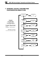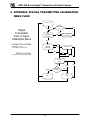
1
AMC-400
Series
Digital Transmitter
with Smart Sensor
USER MANUAL
IMPORTANT:
Please read the installation and operating instructions completely and
carefully before starting.
Filename: 3242405A.doc
Copyright ©, March 4, 2011, AMC
The Armstrong Monitoring Corporation
215 Colonnade Road South, Ottawa, Ontario, Canada K2E 7K3
Tel: (613) 225-9531 • Fax: (613) 225-6965 • Canada & U.S. Toll Free: 1-800-465-5777
E-mail: [email protected] • Internet: www.armstrongmonitoring.com
AMC-400 Series Digital Transmitter with Smart Sensor
ii
AMC-400 Series Digital Transmitter with Smart Sensor
TABLE OF CONTENTS
Section Title
Page
1
GENERAL INFORMATION ...................................................................................... 1
1.1 WARRANTY....................................................................................................... 1
1.2 LIABILITY........................................................................................................... 1
1.3 PRODUCT RETURN ......................................................................................... 1
1.4 CONTACT INFORMATION................................................................................ 2
1.5 MODIFICATIONS AND SUBSTITUTIONS......................................................... 2
1.6 ORGANIZATION OF THE MANUAL.................................................................. 2
1.7 GLOSSARY ....................................................................................................... 3
2 PRODUCT INFORMATION...................................................................................... 4
2.1.1
2.1.2
TRANSMITTER MODULE SPECIFICATION ........................................................ 4
SENSOR MODULE(S) SPECIFICATION.............................................................. 4
3
PRODUCT DESCRIPTION ...................................................................................... 6
3.1 OVERVIEW........................................................................................................ 6
3.2 FRONT LID OVERVIEW .................................................................................... 7
3.3 REAR LID OVERVIEW ...................................................................................... 9
3.4 SMART SENSOR 2 OVERVIEW ..................................................................... 11
4 INSTALLATION ..................................................................................................... 13
4.1 LOCATION AND MOUNTING.......................................................................... 13
4.1.1
4.2
CONDUIT MOUNTING ........................................................................................14
WIRING............................................................................................................ 14
4.2.1.1
4.2.1.2
5
POWER SUPPLY .........................................................................................16
COMMUNICATION.......................................................................................16
OPERATION AND CALIBRATION ........................................................................ 18
5.1 OPERATION .................................................................................................... 18
5.1.1
5.1.2
5.1.3
5.1.4
5.1.5
5.2
5.3
TRANSMITTER JUMPER....................................................................................18
TRANSMITTER AND SMART SENSOR 2...........................................................18
TRANSMITTER STATUS LED ............................................................................21
TROUBLESHOOTING MODBUS USING THE TRANSMITTER STATUS LED ...22
SENSOR STATUS LED.......................................................................................23
INITIAL CONFIGURATION.............................................................................. 24
CALIBRATION ................................................................................................. 26
5.3.1
5.3.2
5.3.3
5.3.4
REQUIRED EQUIPMENT; EXCHANGE PROGRAM...........................................27
REQUIRED EQUIPMENT; ON-SITE CALIBRATION ...........................................27
CALIBRATION PROCEDURE .............................................................................27
GAS TEST AND SERVICE MODES ....................................................................29
6
MAINTENANCE ..................................................................................................... 31
6.1 GENERAL ........................................................................................................ 31
6.2 SCHEDULED CALIBRATION .......................................................................... 31
6.3 SENSOR/TRANSMITTER REPLACEMENT.................................................... 31
7 APPENDIX: DIGITAL TRANSMITTER CONFIGURATION MENU FLOW ............ 32
8 APPENDIX: DIGITAL TRANSMITTER CALIBRATION MENU FLOW.................. 33
9 APPENDIX: USER SUPPORTED MENU GUIDE .................................................. 34
10
APPENDIX: MODBUS REGISTER MAP............................................................ 39
iii
AMC-400 Series Digital Transmitter with Smart Sensor
LIST OF FIGURES
Figure Title
Page
Figure 3-1 Front Lid View........................................................................................................... 7
Figure 3-2 Rear Lid View ........................................................................................................... 9
Figure 3-3 Smart Sensor 2 View ...............................................................................................11
Figure 4-1 Conduit Mounting.....................................................................................................14
Figure 4-2 Example of Electrical Wiring of Digital Transmitter(s) ...............................................15
Figure 4-3 Example of Connections to a AMC-1DAX Monitor ...................................................16
Figure 5-1 Front Panel User Interface .......................................................................................20
iv
AMC-400 Series Digital Transmitter with Smart Sensor
1 GENERAL INFORMATION
1.1 WARRANTY
The AMC-400 Digital Transmitter is warranted against defects in material and
workmanship for a period of two years from date of delivery. Maintenance items are not
warranted. During the warranty period, The Armstrong Monitoring Corporation will repair
or replace components that prove to be defective in the opinion of AMC. Any equipment
deemed to be defective by the user should be returned to The Armstrong Monitoring
Corporation for evaluation (see product return below). Site visits by Armstrong
personnel, to evaluate/repair equipment, are not covered by this warranty unless covered
under site contract. AMC is not liable for auxiliary interfaced equipment, nor for
consequential damage. This warranty shall not apply to any product, which has been
modified in any way, which has been repaired by any other party other than a qualified
technician or authorized AMC representative, or when failure is due to misuse or
conditions of use.
Note: extended warranty mail in calibration programs is available (please call 1-800-4655777) or through contacts at www.armstrongmonitoring.com
1.2 LIABILITY
All AMC products must be installed and maintained according to instructions.
qualified personnel should install and maintain the equipment.
Only
AMC shall have no liability arising from auxiliary interfaced equipment, for consequential
damage, or the installation and operation of this equipment. AMC shall have no liability
for labor or freight costs, or any other costs or charges in excess of the amount of the
invoice for the products.
THIS WARRANTY IS IN LIEU OF ALL OTHER WARRANTIES, EXPRESSED OR IMPLIED,
AND SPECIFICALLY THE WARRANTIES OF MERCHANTABILITY AND FITNESS FOR A
PARTICULAR PURPOSE. THERE ARE NO WARRANTIES THAT EXTEND BEYOND THE
DESCRIPTION ON THE FACE THEREOF.
WARNING
CHECK TO ASSURE THE WORKING AREA IS FREE FROM HAZARDS DURING
INSTALLATION OR WHEN PERFORMING MAINTENANCE, AND USE PROPER
PRECAUTIONS.
1.3 PRODUCT RETURN
All products returned for warranty or service should be shipped by prepaid freight and
will be accepted only with RMA or repair number issued by AMC. All products returned
to the client will be shipped by freight collect.
1
AMC-400 Series Digital Transmitter with Smart Sensor
1.4 CONTACT INFORMATION
For information please call 1-800-465-5777 or through contacts at
www.armstrongmonitoring.com or through email directly at
[email protected].
1.5 MODIFICATIONS AND SUBSTITUTIONS
Due to an ongoing development program, AMC reserves the right to substitute
components and change specifications at any time without incurring any obligations
1.6 ORGANIZATION OF THE MANUAL
This manual provides the following major sections:
1. PRODUCT DESCRIPTION - This section illustrates the product features with a brief
description.
2. INSTALLATION – This section illustrates the installation of the product, describing the
mounting, wiring for power and communication.
3. OPERATION AND CALIBRATION – This section discusses in detail the operation and
procedure for operating and calibrating this product.
4. MAINTENANCE – This section list the maintenance schedule and options associated with
this product.
2
AMC-400 Series Digital Transmitter with Smart Sensor
1.7 GLOSSARY
Alarm
Calibration
Calibration Gas
DT
Gas Concentration
PPM
Percent by volume
RS-485
Span
SS2
T90
T99
Zero Buffering
Zero Gas
Alarm is an audible, visual, or physical
presentation designed to warn the instrument
user that a specific level of a dangerous
gas/vapor concentration has been reached or
exceeded.
Calibration is the procedure used to adjust the
instrument for proper response.
Calibration Gas is a gas of known
concentration(s) used to set the instrument
span or alarm level(s).
Digital Transmitter
Gas Concentration is measured:
• PPM
Parts Per Million (1% volume = 10,000PPM)
Concentration of gas in a mixture expressed as
a percentage of total volume.
Superseded with EIA-485 or TIA-485
Full range of a sensor i.e. a CO sensor with a
full scale of 0-100 PPM has a 100 PPM span.
Smart Sensor 2
Response Time in seconds to achieve 90% gas
concentration reading. This a typical
calibration point that allows for sensor aging,
but tends to be less accurate than a T99
calibration,
Response Time in seconds to achieve 99% gas
concentration reading. This is a more accurate
calibration point.
Zero buffering is transmitter function which
forces the gas concentration reading to zero
when sensor is exposed to low concentration of
a gas. The zero buffers is provided in the
sensor specification.
Zero gas is gas with no concentration. Clean
air is an excellent source for zero calibration.
A known gas concentration can be entered
during zero calibration.
3
AMC-400 Series Digital Transmitter with Smart Sensor
2 PRODUCT INFORMATION
The AMC-400 Series Digital Transmitter with Smart Sensor is a two part assembly;
Transmitter and Smart Sensor module. Both modules have Microcontroller (MCUs) to
manage and communicate the information in a digital formal. The Transmitter
communicates with a monitor (i.e. AMC-1DAX) and carries a Smart Sensor module. The
monitor and transmitter communicate to each other over RS-485 using MODBUS/RTU.
The smart sensor acquires data from an electrochemical gas sensor and communicates
its gas concentration to the transmitter. The smart sensor module is designed for
modular Exchange Program for calibration purpose.
Note:
All Armstrong Monitoring systems must be installed and maintained according to
instructions to assure proper operation. Only qualified personnel should install and
maintain the equipment. For exchange, re-calibration or extended warranty programs
information please call 1-800-465-5777 or through contacts at
www.armstrongmonitoring.com
2.1.1 TRANSMITTER MODULE SPECIFICATION
Transmitter Order Number…………...
………...
Power Supply
Requirement……………………..
Two Wire optional Shield
12 to 24 VDC/AC
Warranty…………………………………
2 Years
Operating
…………………………
Operating
……………………………..
Relative
………………………………..
AMC-400A
Temperature
-20° to 50° C
Pressure
0.9 to 1.1 atm
Humidity
15 to 90% RH, non-condensing
Two Wire with Shield
Modbus RTU over RS-485
9600 Baud, 8bit Even Parity.
Signaling…………………………………...
2.1.2 SENSOR MODULE(S) SPECIFICATION
Gas
Type………………………………….….…...
CARBON MONOXIDE (CO)
Sensor Order Number…………………….……
AMC-91A0F
Sensor Height Above Finished Floor
4-6 Feet
4
AMC-400 Series Digital Transmitter with Smart Sensor
Sensor Life…….…………………………………
6 Years
Sensor
Warranty…………………………………
3 Years
Span Gas …………………………...……………
0-100ppm
Zero Buffering of Display
Calibration
Adapter
Number………………
<8ppm
Part
AMC-C1-FK1
Gas Flow Rate
.5L/min.
Gas
Type………………………………….….…...
NITROGEN DIOXIDE (NO2)
Sensor Order Number…………………….……
AMC-98AHC
Sensor Height Above Finished Floor
4-6 Feet
Sensor Life…….…………………………………
2 Years
Sensor
Warranty…………………………………
1 Years
Span Gas …………………………...……………
0-10.0ppm
Zero Buffering of Display
Calibration
Adapter
Number………………
<0.8ppm
Part
AMC-C1-FK2
Gas Flow Rate
.5L/min.
5
AMC-400 Series Digital Transmitter with Smart Sensor
3 PRODUCT DESCRIPTION
The AMC-400 Digital Transmitter is designed to provide continuous, reliable monitoring
of ambient air for the target gas listed in the SENSOR MODULE(S) SPECIFICATION. This
unit is hot pluggable and powered by either AC or DC power source and provides digital
representation of the gas concentration detected. A digital gas concentration display is
provided, which may be configured to remain blank. Each sensor/transmitter unit is
factory calibrated, and is ready for field installation and operation.
Each sensor module features alarm indicators and connection terminal blocks, as listed
and described below.
3.1 OVERVIEW
The AMC-400 Digital Transmitter consists of three main components;
•
•
•
PVC Enclosure,
Lid Assembly,
Smart Sensor 2 Assembly.
The following three drawings are provided to briefly describe these components.
6
AMC-400 Series Digital Transmitter with Smart Sensor
3.2 FRONT LID OVERVIEW
Display
2
4
Smart Sensor 2
status LED
5
Modbus Address
3
Transmitter status
LED
6
Sensor & Vent
7
Push button
1
Enclosure
Figure 3-1 Front Lid View
7
AMC-400 Series Digital Transmitter with Smart Sensor
1. Enclosure:
2. Digital Display:
3. Transmitter Status LED:
4. Smart Sensor 2 Status LED:
5. MODBUS Address
6. Sensor & Vent
7. Pushbutton:
Enclosure and Lid Assembly, PVC 4”x4” Wall mount
with mount points. Enclosure Lid attaches with four
screws.
Displays gas concentration & Status information, 3 Digit
User Interface for configuration
Red/Green LED
Indicates status of Transmitter.
Red/Green LED
Indicates status of integral Smart Sensor.
This is a write on area matching the MODBUS node ID
(Address). The indication here may be factory set and
can be changed as needed.
This vent allows target gas to flow into the sensor. The
vent is also used for gas calibration.
Momentary On/Off Pushbutton
User Interface for Configuration.
8
AMC-400 Series Digital Transmitter with Smart Sensor
3.3 REAR LID OVERVIEW
14
Modbus Termination
13
Smart Sensor 2 Termination
12
SS2 female connector
15
SS2 mounting hole
Transmitter board
Sensor
SS2 Board mounted
Mounting Standoffs
RS485 A
RS485 B
CGND
SIG GND
AC 1
AC 2
GND VDD V+
SS2 board
11
10
9
8
V+ test point
VDD test point
GND test point
Power and communication
connector
Figure 3-2 Rear Lid View
Note:
When mounting the Smart Sensor module, it is possible for its male header pins to
miss the receptacle of the Digital transmitter completely.
Warning:
Care must be taken when connecting services to Power and Communication
Connector. Avoid using SIG GND for powering. Cable shield(s) are to be connected to
CGND. Mixing power and communication connections can cause permanent damage.
Consistent polarity of RS-485 wire is required throughout network for proper system
operation.
9
AMC-400 Series Digital Transmitter with Smart Sensor
8. Power and Communication
Connector:
This 6 pin male plug connector contains both power
and communication network connection points. The
power is normally 24VDC and the communication
network is MODBUS over RS-485.
9. GND Test Point:
This GND Test Point is to be used by service
technicians only with appropriate instrumentation such
as a voltmeter. It is the signal reference point for the
digital transmitter control logic.
10. VDD Test Point:
This VDD Test Point is to be used by service
technicians only. It is the digital transmitter control
logic supply voltage and must be 5+-5% Volts DC.
11. V+ Test Point:
This V+ Test Point is to be used by service technicians
only. It is the digital transmitter rectified unregulated
power input and must be 8-35 Volts DC.
12. SS2 Female Connector:
This 7 pin connector mates with the Smart Sensor 2
Assembly male connector. This connector carries the
power and communication for Smart Sensor 2.
13. Smart Sensor 2
Termination:
Default position: AC Termination (Pins 1-2). This
termination allows AC or DC Termination for the Smart
Sensor II RS-485 signaling.
14. MODBUS Termination:
Default position: No Termination (Pin 2). This
termination allows AC or DC Termination for the
MODBUS RS-485 signaling. Use AC Termination (Pin 12) when transmitter is an end point on bus.
15. SS2 Mounting Hole:
This mounting hole contains two standoffs to support
the Smart Sensor II Assembly. One standoff is a stud
the other is nylon press-fit.
10
AMC-400 Series Digital Transmitter with Smart Sensor
3.4 SMART SENSOR 2 OVERVIEW
Smart Sensor 2 Board
16
SS2 male connector
SIG
Front
Back
22
21
3
4
5
7
8
9
0
VER
2
6
REV
1
1
2
3
4
5
6
7
8
9
0
CTR
VREF test point
19
SNS1
SIG
CTR
VREF
20
Sensor Location
GND
SNS4
VDD
SNS2
SNS3
18
VDD test point
17
GND test point
Figure 3-3 Smart Sensor 2 View
16. SS2 Male Connector:
This 7 pin connector mates with the Digital Transmitter
Assembly female connector. This connector carries the
power and communication.
17. GND Test Point:
This GND Test Point is to be used by service
technicians only with appropriate instrumentation such
as a voltmeter. It is the signal reference point for the
smart sensor 2 control logic.
18. VDD Test Point:
This VDD Test Point is to be used by service
technicians only. It is the smart sensor 2 control logic
supply voltage and must be 3.42 to 3.78 Volts DC.
11
AMC-400 Series Digital Transmitter with Smart Sensor
19. VREF Test Point:
This VREF Test Point is to be used by service
technicians only. It is the potentiostat sensor reference
and must be 1.8 Volts DC.
20. Sensor:
This component may be a variety of 2 or 3 pin
electrochemical sensors. This component is securely
fastened with glue to Smart Sensor 2 Assembly.
21. CTR Test Point:
This CTR Test Point is to be used by service
technicians only with appropriate instrumentation such
as a voltmeter. It is the potentiostat counter output used
by a 3 pin electrochemical sensor. Under ideal
operation zero gas situation it is normally 1.8 Volts DC
VREF.
22. SIG Test Point:
This Sig Test Point is to be used by service technicians
only with appropriate instrumentation such as a
voltmeter. It is the potentiostat sensor output used.
Under normal operation zero gas situation it tracks the
1.8 Volts DC VREF. When CO gas is applied this SIG
Test Point increases toward 3.6 Volts DC. When NO2
gas is applied this SIG Test Point decreases towards 0
Volts DC.
12
AMC-400 Series Digital Transmitter with Smart Sensor
4 INSTALLATION
The installation of the AMC-400 Digital Transmitter is very important as the operational
quality is a direct result of the quality of the installation. The following sections provide
guidelines for installation; location and mounting, wiring, and cable selection.
4.1 LOCATION AND MOUNTING
Mount the AMC-400 Digital Transmitter sensor/transmitter on a solid, non-vibrating
surface or structure in an area where the ambient concentration of gas is not directly
affected by the presence of clean air supply, ventilation systems, or blockage by
surrounding articles and sources of interference gases. Please, refer to local codes for
sensor/transmitter installation information. The installer is required to provide any
mounting hardware that may be required. The AMC-400 Digital Transmitter
sensor/transmitter circuit board(s) with sensor is removable from the enclosure for ease
of installation. The recommended mounting height is specified in the SENSOR
MODULE(S) SPECIFICATION. The conduit entry is from bottom of box to avoid moisture
flow into box through conduit.
Notes:
Mount enclosure with the sensor located as shown is Figure 4-1. This will ensure
correct orientation.
Warning:
It is possible to damage both the Smart Sensor 2 and Digital Transmitter assemblies if
Smart Sensor 2 is plugged or unplugged under power. This product does not support
hot powering of the Smart Sensor 2 unit. Please completely disconnect power from
Digital Transmitter before replacing Smart Sensor 2 assembly.
Installing conduit from top of box will allow moisture from condensation to drip down
into circuit assembly. Damage caused by this type of installation will void warranty.
Caution:
Conduit entry is from the bottom of enclosure to avoid damage to electronic
components from condensation build-up in the conduit.
13
AMC-400 Series Digital Transmitter with Smart Sensor
4.1.1 CONDUIT MOUNTING
4.600
Mounting screws
(4 places)
Ø0.200
2.100
2.470
(4Plcs)
23
Mounting holes
Wiring Conduit
Wiring
Figure 4-1 Conduit Mounting
23. Mounting Holes:
Wall mounts with 4 holes.
4.2 WIRING
The AMC-400 Digital Transmitter employs a four wire system which has two main wiring
systems: the monitor communication (two wires) and power supply wiring (two wires).
A two conductor, shielded cable is used to connect the RS-485 signals from the AMC-400
Digital Transmitter to the monitor.
A two conductor, shielded cable is recommended to connect the power from the AMC400 Digital Transmitter to the power supply. Shielded cable is optional for power supply
wiring.
For best signal transmission and maximum noise rejection, it is recommended to
connect the cable shields to chassis ground at the monitor.
Below are example electrical wiring diagrams for an application where monitor supplies
both power and communication.
14
AMC-400 Series Digital Transmitter with Smart Sensor
Warning:
Installing monitor communication without shield will produce unreliable system wide
failure. Armstrong Monitoring Corporation will not support this type of installation.
To Monitor
AC2
AC1
CGND
RS 485 B RS 485 A
Unit 1
Unit 2
RS 485 A
RS 485 A
RS 485 B
RS 485 B
CGND
CGND
SIGGND
SIGGND
AC1
AC1
AC2
AC2
Figure 4-2 Example of Electrical Wiring of Digital Transmitter(s)
MONITOR
AC modbus termination on last unit
Unit 1
R1
R2
R3
R4
STATUS
DISPLAY
1
2
3
CAL
4
5
6
CONTROL
7
SETUP
8
0
1 2+
3 4+
5 6+
7 8 +
9 24 VDC PWR
10 +
11 12 + NETWORK
Unit 2
IN
9
ENTER
CHASSIS GND POINTS
RS 485 A
RS 485 B
CGND
SIG GND
AC 1
AC 2
GND VDD V+
GND VDD V+
CONNECTOR
Note
1. There is always AC modus termination on the last transmitter connected in the system
2. More than 2 transmitters can be connected to a single monitor
3. Power shielded cabling is optional
15
1
2
3
4
5
6
7
8
9
10
11
12
24 VDC PWR IN
NETWORK
AMC-400 Series Digital Transmitter with Smart Sensor
Figure 4-3 Example of Connections to a AMC-1DAX Monitor
Warning:
Care must be taken when connecting services to Power and Communication
Connector. Avoid using SIG GND for powering. Cable shield(s) are to be connected to
CGND. Mixing power and communication connections can cause permanent damage.
Consistent polarity of RS-485 wire is required throughout network for proper system
operation.
4.2.1.1 POWER SUPPLY
The AMC-400 Digital Transmitter assembly is to be powered by the AMC-1DAX monitor
Power Supply. An AMC-400 Digital Transmitter is powered through a cable on AC1 and
AC2 connections as shown in the REAR LID OVERVIEW; item 8 Power and
Communication Connector:.
The rectified unregulated V+ Test Point: voltage must be between 8 and 42 Volts DC. The
shield of the cable should be connected to chassis ground on CGND at the monitor
power supply and the AMC-400 Digital Transmitter.
Caution:
Care must be taken when installing to ensure that all Digital Transmitters are
connected with the same power supply polarity across the network. Digital
Transmitter AC2 should be connected to + power terminal and Digital Transmitter AC2
should be connected to – power terminal. Using SIG GND for powering should be
avoided.
The recommend power cable should be a two wire conductor plus shield cable with #18
AWG. The cable length must not exceed a distance that prevents the Digital Transmitter
from obtaining a minimum voltage of 8 Volts DC at V+ Test Point.
4.2.1.2 COMMUNICATION
The AMC-400 Digital Transmitter assembly is to be controlled by the AMC-1DAX monitor
or other MODBUS masters. The AMC-1DAC has the possibility of managing 80 nodes on
the network. All nodes are connected to same two communication signals; RS485A and
RS485B. The AMC-400 Digital Transmitter communicates through a cable connection on
RS485A and RS485B as shown in the REAR LID OVERVIEW; item 8 Power and
Communication Connector:
Caution:
Care must be taken when installing to ensure that all Digital Transmitters are
connected with the same MODBUS polarity across the network. Digital Transmitter
RS485A should be connected to + network terminal and Digital Transmitter RS485B
should be connected to – network terminal. Using SIG GND for powering should be
avoided.
The recommend cable should be a two wire twisted pair conductor plus shield cable and
has a characteristic impedance of 120ohms.
16
AMC-400 Series Digital Transmitter with Smart Sensor
The total cable length for the entire network should not exceed 1000 M. Please refer to
MODBUS OVER SERIAL LINE SPECIFICATION AND IMPLEMENTATION GUIDE
V1.0 27/44
This cable should be a two wire twisted pair conductor shielded cable. The shield of the
cable should be connected to chassis ground on CGND at the monitor and the AMC-400
Digital Transmitter.
MODBUS AC termination is required for last unit of bus; please refer to REAR LID
OVERVIEW MODBUS Termination; item #14 for details.
17
AMC-400 Series Digital Transmitter with Smart Sensor
5 OPERATION AND CALIBRATION
This section describes how the functionalities of the AMC-400 Digital Transmitter are
operated and performed. Please consult the operation and initial configuration chapters
below before attempting to operated the AMC-400 Digital Transmitter.
Warning:
It is possible to damage both the Smart Sensor 2 and Digital Transmitter assemblies if
Smart Sensor 2 is plugged or unplugged under power. This product does not support
hot powering of the Smart Sensor 2 unit. Please completely disconnect power from
Digital Transmitter before replacing Smart Sensor 2 assembly.
5.1 OPERATION
5.1.1 TRANSMITTER JUMPER
The Digital Transmitter has two straps; Smart Sensor 2 Termination and MODBUS
Termination. Please refer to REAR LID OVERVIEW for details.
5.1.2 TRANSMITTER AND SMART SENSOR 2
The AMC-400 Digital Transmitter sensor/transmitter is factory calibrated for the gas listed
in the Product Information (Section 2) at the beginning of this manual.
The
sensor/transmitter should not require re-calibration when first installed and powered up,
but a test for correct sequence of operation is recommended after a stabilization period
of five minutes. Activity on the LED(s) indicates that the board is powered on.
At power up, the display runs through the following sequence:
1. Indicates the software/Hardware versions and performs a self test
2. Display sensor stabilization status
3. Displays the gas type
4. Displays the detected level
Note:
The transmitter will experience a reboot and repeat the above sequence if no MODBUS
traffic is detected for a period of five minutes. Additionally a failed transmitter will
reboot after one to two minutes.
Additionally the AMC-400 Digital Transmitter can insert other sensor status between gas
type and gas concentration. This following sensor status is available:
18
AMC-400 Series Digital Transmitter with Smart Sensor
Sensor Status
“PUP”
Definition
Sensor in stabilization Power Up Period
“CAL”
Sensor needs CALibration
“OFL”
Sensor in Over Flow out of range state.
Gas concentration is exceeding full span
range of sensor.
“EOL”
Sensor has reached End Of Life
Action
Wait up to 5 minutes for
sensor to stabilize.
Consult CALIBRATION
and MAINTENANCE
sections in this manual.
Consult AMC for
appropriate Smart Sensor
type and use. It is not
recommended to operate
Smart Sensor outside
specified operating limits.
Gas concentration is this
mode may be at
hazardous levels.
Contact AMC for
replacement. Sensor
operated beyond EOL
may provide erroneous
readings.
In near zero gas and after the stabilization period, the transmitter will send accurate gas
concentration MODBUS packets to the monitor or controller. Although the
electrochemical sensors are very selective, there are some interference gases which can
cause a response from the sensor. In the case of a large response, please check
background gas potential or the possibility of an interference gas being present.
Caution:
When the gas concentration exceeds the full scale range, the display will alternate
between the reading value and the letters “OFL” for overflow. Refer to 2.1.2 SENSOR
MODULE(S) SPECIFICATION for SPAN, consult AMC for alternative Smart Sensor 2
types. It is not recommended to operate Smart Sensor outside specified operating
SPAN. Gas concentration is this mode may be at hazardous levels.
The front panel view below shows the four areas of user interface; Pushbutton, Display,
TX Status, and Sensor Status. These user interfaces are briefly described below and
referenced in more detail under the initial configuration and calibration sub-sections.
19
AMC-400 Series Digital Transmitter with Smart Sensor
Figure 5-1 Front Panel User Interface
Note:
The Pushbutton (reference point 1) is positioned behind the front panel and requires a
small TOOL SCREWDRVR SLOT ESD 1.5MM, Wiha 27215 to access it through a small hole.
The Pushbutton allows a user to navigate through configuration menu. The pushbutton
has two states; short and long button press. Short press is less than two seconds while
long press is greater than two seconds. Feedback of the pushbutton state is provided on
the display. A short press will display both decimal points, while a long press will display
“SEL”. As an example the pushbutton must be pressed and held for at least 2 seconds to
enter configuration. The display will indicate “SEL” when user has held the pushbutton
long enough to enter the configuration menu.
The Display has 3 character positions with two decimal points, each character has 7
segments. The LCD can display numbers and various alphabetic characters. Some
alphabetic characters are upper case while others are lower case. In normal operation
the display will cycle between the gas concentration and gas type, in configuration the
display is used to indicate configuration titles and items. By default the Gas
concentration is displayed in PPM and may or may not have a decimal point. The Gas
type is displayed in alphanumerical characters as an example “co” indicates Carbon
Monoxide and “no2” indicates Nitrogen Dioxide.
The TX Status is a green and red LED to indicate activity of the MODBUS link and
transmitter health and state. As an example a slow blinking green TX status indicates
20
AMC-400 Series Digital Transmitter with Smart Sensor
healthy MODBUS activity detected, while a period of fast blinking red TX status can
indicate a momentary MODBUS fault. Please refer to TRANSMITTER STATUS LED for
further details.
The Sensor Status is a green and red LED to indicate activity of the Smart Sensor link
and Smart Sensor health and state. As an example a slow blinking green Sensor status
indicate healthy activity detected, while a period of fast blinking red Sensor status can
indicate a momentary sensor bus fault. Please refer to SENSOR STATUS LED for further
details.
Note:
AMC-400 Digital Transmitter LED will appear to blink slow green even though it is not
being accessed by a monitor. This is the case when MODBUS address is not properly
configured. Use 5.3.4 GAS TEST AND SERVICE MODES to verify proper configuration
this will allow gas concentration to be observed at the monitor or controller.
5.1.3 TRANSMITTER STATUS LED
The Transmitter Status LED under normal operation should be slow blinking green
indication. Slow blinking green indicates MODBUS communication detected and no
transmitter faults. Numerous transmitter faults can occur under various situations and is
indicated with momentary fast blinking red indication. A fast blinking green indicated no
MODBUS communication present and no transmitter faults.
Note:
AMC-400 Digital Transmitter Status LED will momentarily fast blink red under a minor
transmitter fault situation, such as erroneous MODBUS packet. Consult AMC for
service if minor transmitter fault persists.
21
AMC-400 Series Digital Transmitter with Smart Sensor
Below is the possible Transmitter Status LED:
Transmitter LED State
Definition
Slow Blinking Red
Transmitter initializing.
Slow Blinking Green
Transmitter is healthy.
Fast Blinking Green
Transmitter is healthy,
but no MODBUS
communication
detected.
Slow Blinking
Transmitter is in
Green/Red
configuration mode.
Fast Blinking
Transmitter is in
Green/Red
gassing state of
calibration.
Fast Blinking Red
Transmitter has
experienced a minor
fault in the last 10
seconds of operation.
Solid or long period
Red, Green or Orange
LED Extinguished
Transmitter has
experienced a severe
fault.
Transmitter is powered
off.
Action
Wait for initialization to complete.
No action required.
Check if monitor is MODBUS
connected and not in setup.
Complete configuration and exit.
Complete calibration and exit.
Check if transmitter and/or other
system components have valid
operating limits (i.e. connections,
power supply, temperature, and
MODBUS addressing). Consult
AMC for service if status persists.
Wait one to two minutes for unit to
enter normal mode. Consult AMC
for service if status persists.
Check transmitter wiring or power
supply state. Consult AMC for
service if status persists.
5.1.4 TROUBLESHOOTING MODBUS USING THE TRANSMITTER STATUS LED
The Transmitter Status LED indirectly provides a MODBUS monitor function. Using this
LED in conjunction with other transmitters can help in diagnostic of MODBUS faults.
Here is a list of troubleshooting guidelines of the Transmitter Status LED:
A. If all transmitters blink fast green and the monitor is in operation mode then the
MODBUS wiring is likely disconnected at the monitor.
B. If one or more transmitter(s) in a chain are blinking fast green and a unit closer to
the monitor is blinking slow green then a MODBUS disconnection point begins
after the slow blinking green unit.
C. If a transmitter is blinking fast red and other transmitter units are blinking slow
green then check that the MODBUS connections are not reversed on the flashing
red unit.
D. If a transmitter blinks slow green, but the monitor indicates “na” for that unit then
the transmitter unit needs its MODBUS address to be assigned.
E. If two transmitter units blink slow green, but all other transmitter units indicate
fast blinking red, then the two slow blinking green transmitter units have the
same MODBUS address.
F. If the monitor appears to be operating well with one or more transmitters, but
transmitter unit(s) have fast blinking red from time to time, then MODBUS signal
degradation is present. Check that the both MODBUS signals wires and shield are
properly connected.
22
AMC-400 Series Digital Transmitter with Smart Sensor
5.1.5 SENSOR STATUS LED
The Sensor LED Status under normal operation has a slow blinking green indication.
Slow blinking green indicates good Smart Sensor communication detected and no
sensor faults. Numerous sensor faults can occur under various situations and is
indicated with momentary fast blinking red indication.
Caution:
Sensor LED status will momentarily fast blink red under a minor sensor fault situation,
such as a packet error. Consult AMC for service if minor sensor fault persists.
Below is the possible Sensor LED Status:
Sensor LED State
Definition
Slow Blinking Red
Smart Sensor
initializing.
Slow Blinking Green
Smart Sensor is healthy.
Fast Blinking Green
Smart Sensor is healthy,
but no communication
detected.
Slow Blinking
Smart Sensor is in
Green/Red
configuration mode.
Fast Blinking
Smart Sensor is in
Green/Red
gassing state of
calibration.
Blinking Red for
Smart Sensor requires
10seconds every
services either
minute of Slow
calibration or has
Blinking Green
reached end of life. DT
display will complement
this with “CAL” or “EOL”
indication.
Fast Blinking Red
Smart Sensor has
experienced a minor
fault in the last 10
seconds of operation.
Solid or long period
Red, Green or Orange
LED Extinguished
Smart Sensor has
experienced a severe
fault.
Smart Sensor is
powered off.
Action
Wait for initialization to complete.
No action required.
Check if Smart Sensor is properly
connected to TX.
Complete configuration and exit.
Complete calibration and exit.
Consult calibration section in this
manual or contact AMC. It is not
recommended to operate Smart
Sensor after end of life or when
calibration is needed. Sensor
operated beyond CAL or EOL may
provide erroneous readings.
Check if Smart Sensor has valid
operating limits (i.e. power supply,
temperature, and Smart Sensor
addressing). Consult AMC for
service if status persists.
Wait one to two minutes for unit to
enter normal mode. Consult AMC
for service if status persists.
Check Smart Sensor wiring or
power supply state. Consult AMC
for service if status persists.
Note:
The Smart Sensor will experience a reboot and enter initialization state (slow blinking
RED Sensor Status LED) if no transmitter requests are detected for a period of five
minutes. Additionally a failed Smart Sensor will reboot after one to two minutes.
23
AMC-400 Series Digital Transmitter with Smart Sensor
5.2 INITIAL CONFIGURATION
Initial installation requires a unique MODBUS address to be configured. The current
MODBUS address may be pre-configure and labeled on the front panel in small box (see
front panel view item 5). User can change the MODBUS address by entering
configuration. MODBUS addresses must be in the range of 1-247. Please refer to
Appendix for menu flow diagrams and guide.
Caution:
An invalid MODBUS address may cause other devices to malfunction. It is important
to carefully map out MODBUS addresses.
Note:
AMC-400 Digital Transmitter will automatically exit current level of configuration after 1
minute of inactivity without change. This can be useful when user is lost or unsure of
current modification.
The AMC-400 Digital Transmitter configuration is divided into 6 areas;
•
•
•
•
•
•
MODBUS Configuration
Smart Sensor Configuration
Digital Transmitter Configuration
Zero Calibration
Span Calibration
Service Modes
1. To enter configuration press and hold the pushbutton for 2 seconds or more until the
display shows “SEL”. When the pushbutton is released the Configuration Menu title
“-CF” will be displayed.
2. The possible items in configuration are:
“-CF” Configuration Title and Exit Point
“A01” MODBUS Configuration
“A02” Smart Sensor Configuration
“A03” Digital Transmitter Configuration
“A04” Zero Calibration
“A05” Span Calibration
“A06” Service Modes
3. At this point the user can immediately exit configuration by push and holding the
pushbutton for >2 seconds and releasing. Alternatively the user can scroll through
the above 6 choices by short pressing the pushbutton (<2seconds). The list is
circular in nature.
Note:
Configuration titles with a negative sign are exit points. Just press and hold the
24
AMC-400 Series Digital Transmitter with Smart Sensor
pushbutton for >2seconds and release to get to the previous level. Scrolling with quick
button presses will normally cycle you to an exit point without change.
4. To enter MODBUS Configuration the user must press and hold the pushbutton for >2
seconds and release at the item A01. The MODBUS title “-FB” will be displayed.
5. To configure the MODBUS address short press to the item “F01” and press and hold
for >2seconds and release to enter sub-item. At this point the current MODBUS
address will be displayed; a short press returns you back to “F01” which can lead
you to an exit point.
6. To modify the MODBUS address press and hold for >2seconds and release to edit the
first digit of the address. The least significant digit can now be changed, scroll
quickly with short presses and cycle through the number choices from the current
number to 9 and then back to 0. Press and hold >2seconds and release to move to
next most significant digit position. Repeat sequence for second digit and third digit.
When the MODBUS address is displayed use a short press to return to “F01”.
7. Use short presses to scroll to item “-FB” and push and hold the pushbutton for >2
seconds and release to return to A01. Use short presses to scroll to item A03.
8. To enter Digital Transmitter Configuration the user must push and hold for
>2seconds and release at item A03. The title “-du” will be displayed. Scroll through
to d01, push and hold for >2seconds and release to enable LCD blanking. LCD will
blank after 1 minute of pushbutton inactivity, pressing the pushbutton restores
display. Alternatively scroll to d02, push and hold for >2seconds and release to
disable LCD blanking. Or scroll to d03, push and hold for >2seconds and release to
enter Digital Transmitter location label. Location labeling allows a unique 3 character
string to be assigned to Digital Transmitter. This procedure is similar to entering the
MODBUS address, but the choices are alphanumeric.
Note:
Currently location label is not required by a monitor or controller and can be used as
needed to store and retain user information.
9. Items A04 to A06 can be skipped for initial configuration.
25
AMC-400 Series Digital Transmitter with Smart Sensor
5.3 CALIBRATION
This calibration procedure is applicable for all versions of the AMC-400 Digital
Transmitter.
Every AMC-400 Digital Transmitter sensor/transmitter is factory calibrated, so each unit
is to be ready for operation after installation and a 5 minute stabilization time.
The AMC-400 Digital Transmitter and Smart Sensors are equipped with Calibration and
End of Life indicators. When calibration or sensor End of Life has occurred the display
will interleave “CAL” or “EOL” respectively during normal gas concentration updates.
Subsequent calibration is required as a part of regular maintenance, and when replacing
the sensor. See the Maintenance section of this manual for the recommended calibration
schedule.
Note:
When the gas sensor needs calibration or has reached end of life the display will
alternate between the reading value and the letters “CAL” or “EOL”.
Warning:
When performing calibration the results are not saved in Smart Sensor until successful
Span procedure has been completed. Powering off unit after Zero procedure and
before completing a successful Span procedure will result in calibration information
being lost. Also failed Span procedure due to user abort or procedure limit checking
leaves the unit with unstable calibration information. It is important to complete a
successful SPAN procedure for unit to function properly.
Caution:
- Only qualified personnel should perform the actual calibration.
- Users new to gas calibration are advised to consult with Armstrong Monitoring
The Armstrong Monitoring Corporation offers the following calibration plans:
1. Factory pre-calibrated exchange replacement smart sensor units
2. On site installation by Armstrong Monitoring
3. On site calibration by Armstrong Monitoring
4. Training by Armstrong Monitoring for end users
For additional details please refer to CONTACT INFORMATION.
26
AMC-400 Series Digital Transmitter with Smart Sensor
5.3.1 REQUIRED EQUIPMENT; EXCHANGE PROGRAM
For qualified personnel, the following is a recommended list of equipment required.
•
•
5/16 Nut driver and Philips and Roberson screw driver set
TOOL SCREWDRVR SLOT ESD 1.5MM, Wiha 27215.
To replace Smart Sensor 2 with pre-calibrated unit, first completely remove power from Digital
Transmitter by unplugging Power and Communication Connector as shown in. Use a Nut driver to
remove nut that is holding Smart Sensor 2 assembly to Digital Transmitter. Carefully remove and
replace Smart Sensor 2 assembly attached to SS2 Female Connector. Replace nut holding Smart
Sensor2 to Digital Transmitter with Nut driver.
Warning:
It is possible to improperly insert SS2 Male Pins into SS2 Female connector.
5.3.2 REQUIRED EQUIPMENT; ON-SITE CALIBRATION
For qualified personnel, the following is a recommended list of calibration equipment
required.
•
•
TOOL SCREWDRVR SLOT ESD 1.5MM, Wiha 27215
Calibration kit, please refer to SENSOR MODULE(S) SPECIFICATION.
5.3.3 CALIBRATION PROCEDURE
The AMC-400 Digital Transmitter is equipped with a calibration feature allowing for oneman calibration at the transmitter location. In most cases it is only Zero and Span
adjustments that are made in field calibrations. All Calibration procedures will
automatically exit to normal operation without change if left inactive for several minutes.
Please refer to Appendix for menu flow diagrams and guide.
Note:
During calibration new gas concentration is not updated to monitor and last gas
concentration value will be reported.
Refer to Figure 5-1 Front Panel User Interface to perform the following calibration
procedure:
1) Cover the sides of sensor with a clean cloth or similar to prevent a draft on the
sensor. The zero calibration can also be used with a gas concentration for a 2
point calibration procedure (as example 5ppm CO gas could use instead of
0ppm). Perform gassing with a calibration adapter that is firmly inserted into
front panel of AMC-400 Digital Transmitter; please refer to 2.1.2 SENSOR
MODULE(S) SPECIFICATION for adapter P/N and gas flow rate.
27
AMC-400 Series Digital Transmitter with Smart Sensor
2) Enter Configuration from normal operation mode by push and holding
pushbutton for >2seconds and then releasing. The configuration title “-CF”
will be displayed. Scroll through to the “A04” item with short presses. To begin
zero calibration enter the “A04” item with a push and hold >2seconds and
release. The zero calibration title “-0C” will be displayed.
3) At this point short press pushbutton to display the Zero Gas Concentration. If
the zero gas concentration is to be modified then push and hold for >2seconds
and release. The gas concentration can be modified one digit at a time similar
to MODBUS address modification in INITIAL CONFIGURATION. Once all digits
have been modified another short press will advance procedure to the gassing
phase. The AMC-400 Digital transmitter may ignore modifications if the gas
concentration entered is not acceptable.
4) At the beginning of zero calibration the AMC-400 Digital Transmitter will
display “GaS” “On”. Begin gassing at this point to perform a T99 type
calibration. The qualified personnel can begin gassing after this point to
perform a T90 type calibration by advancing the procedure to measurement
phase with a press of the pushbutton.
5) During zero gassing measurement the display will indicate either “Inc” or
“dEc
dEc” depending of signal level from sensor increasing or decreasing
respectively. Also the LCD will display the sensor voltage when the gas
concentration is not changing. The measurement phase contains a minimum
and maximum gassing period and will automatically complete after gas
measurement is stable. Proceed to calibration complete by pressing the
pushbutton.
6) During zero calibration complete the AMC-400 Digital Transmitter will display
“GaS” “OFF”. At this point the qualified personnel must accept or reject this
calibration by a push and hold >2seconds or short press respectively. If the
accept is given the AMC-400 Digital Transmitter will check the limits of the
result and accept or reject it by displaying “Acc” or “bAd” respectively. If
result has been rejected the LCD will indicate “bAd”.
7) The zero calibration title “-0C” will be re-displayed for retry or exit. Push and
hold and release to exit. Scroll through to the “A05” item with short presses.
To begin span calibration enter the “A05” item with a push and hold
>2seconds and release. The span calibration title “-SC” will be displayed.
8) At this point short press pushbutton to display the Span Gas Concentration. If
the span gas concentration is to be modified then push and hold for
>2seconds and release. The gas concentration can be modified one digit at a
time similar to MODBUS address modification in INITIAL CONFIGURATION.
Once all digits have been modified another short press will advance procedure
to the gassing phase. AMC-400 Digital transmitter may ignore modification if
the gas concentration entered is not acceptable.
28
AMC-400 Series Digital Transmitter with Smart Sensor
9) At the beginning of span calibration the AMC-400 Digital Transmitter will
display “GaS” “On”. Begin gassing at this point to perform a T99 type
calibration. The qualified personnel can begin gassing after this point to
perform a T90 type calibration by advancing the procedure to measurement
phase with a press of the pushbutton.
10) During span gassing measurement the display will indicate either “Inc” or
“dEc
dEc” depending of signal level from sensor increasing or decreasing
respectively. Also the LCD will display the sensor voltage when the gas
concentration is not changing. The measurement phase contains a minimum
and maximum gassing period and will automatically complete after gas
measurement is stable. The qualified personnel can proceed to calibration
complete by pressing the pushbutton.
11) During span calibration complete the AMC-400 Digital Transmitter will display
“GaS” “OFF”. At this point the qualified personnel must accept or reject this
calibration by a push and hold >2seconds or short press respectively. If the
accept is given the AMC-400 Digital Transmitter will check the limits of the
result and accept or reject it by displaying “Acc” or “bAd” respectively. If
result has been rejected the LCD will indicate “bAd”.
12) At this point the span calibration title “-SC” will be re-displayed for retry or
exit. Push and hold >2seconds and release to exit. Scroll through to the “-CF”
CF
exit point with short presses. Push and hold >2seconds and release to exit
configuration back into normal operation.
5.3.4 GAS TEST AND SERVICE MODES
The AMC-400 Digital Transmitter should be bump tested after calibration to ensure
proper sequence of operation. Gas testing under normal operation provides verification
of full path operation from sensor, to monitor, to interlock. Gas testing under normal
mode requires the re-application of span gas concentration as performed in gassing
phase of calibration. Please refer to Appendix for menu flow diagrams and guide.
Note:
When the gas testing with low concentration gasses the AMC-400 digital transmitter
may display gas concentration of 0. Consult 2.1.2 SENSOR MODULE(S)
SPECIFICATION for Zero buffer gas concentration value.
The AMC-400 Digital Transmitter is equipped with two service modes:
1) Service Mode 1: Gas testing without reporting gas concentration to monitor. This
mode allows sensor sensitivity to be tested locally without alarming the rest of the
building or building automation system. The gas concentration reported to
monitor during this mode will be the last known level.
2) Service Mode 2: Forces gas concentration to monitor without actual gas testing.
This mode allows the monitor alarms or building automation system to be tested
without using gas.
29
AMC-400 Series Digital Transmitter with Smart Sensor
Note:
All service mode procedures will automatically exit to normal operation without
change if left inactive for 10 minutes.
Service Mode 1:
A. To enter Service Mode 1; enter Configuration from normal operation mode by
push and holding pushbutton for >2seconds and then releasing. The
configuration title “-CF” will be displayed. Scroll through to the “A06” item with
short presses. To begin service mode choice enter the “A06” item with a push and
hold >2seconds and release. The service mode title “-SE”
SE will be displayed.
B. Short press pushbutton to scroll to the “SE1” choice. Push and hold >2seconds
and release to enter service mode. The Service Modes will enter a routine;
displaying the gas type and concentration. With Service Mode 1 the qualified
personnel can begin gassing without changing the gas concentration to monitor.
The monitor will continue to receive last known gas concentration. To exit service
modes wait for gas concentration to return to background levels, then push and
hold >2seconds and release.
C. Short press pushbutton to scroll through items to return to “-SE” exit point. Push
and hold >2seconds and release to return to “A06” item. Again short press
pushbutton to scroll through items to return to “-CF” exit point. Push and hold
>2seconds and release to return to normal operation.
Service Mode 2:
A. To enter Service Mode 2; enter Configuration from normal operation mode by
push and holding pushbutton for >2seconds and then releasing. The
configuration title “-CF” will be displayed. Scroll through to the “A06” item with
short presses. To begin service mode choice enter the “A06” item with a push and
hold >2seconds and release. The service mode title “-SE” will be displayed.
B. Short press pushbutton to scroll to the “SE2” choice. Push and hold >2seconds
and release to enter service mode. In Service Mode 2 the qualified personnel must
enter a gas concentration to be forced to the monitor. Once entered the Service
Modes will continuously transmit gas concentration and type to the monitor. This
entry is similar to MODBUS address modification in INITIAL CONFIGURATION. To
exit service modes push and hold >2seconds and release.
C. Short press pushbutton to scroll through items to return to “-SE” exit point. Push
and hold >2seconds and release to return to “A06” item. Again short press
pushbutton to scroll through items to return to “-CF” exit point. Push and hold
>2seconds and release to return to normal operation.
30
AMC-400 Series Digital Transmitter with Smart Sensor
6 MAINTENANCE
Maintenance is a very important activity that should be done at the proper time intervals,
which are discussed below.
6.1 GENERAL
The AMC-400 Digital Transmitter should be brushed or wiped as required, depending on
the rate of accumulation of any dust or dirt.
To avoid sensor damage, the unit MUST NOT be submerged in any liquids. Hosing or
splashing of the unit with any liquids must also be avoided.
6.2 SCHEDULED CALIBRATION
Scheduled calibration
sensor/transmitters.
is
critical
in
maintaining
proper
function
of
gas
It is recommended that the AMC-400 Digital Transmitter be calibrated a minimum of twice
a year or more often for demanding work place applications.
As mentioned, Armstrong Monitoring Corporation offers a number of different
maintenance plans to suit your requirements. Please see CONTACT INFORMATION
section.
6.3 SENSOR/TRANSMITTER REPLACEMENT
When its sensor signal is greatly reduced or unstable, the sensor/transmitter
replacement is required; see section 2.1.2 for replacement sensor P/N.
Please note that the sensor itself is not replaceable. The Smart Sensor 2 and sensor are
replaced as one assembly; please refer to 5.3.1 REQUIRED EQUIPMENT; EXCHANGE
PROGRAM for instructions.
Note:
5 minutes is required for a new sensor to stabilize before calibration.
Warning:
It is possible to damage both the Smart Sensor 2 and Digital Transmitter assemblies if
Smart Sensor 2 is plugged or unplugged under power. This product does not support
hot powering of the Smart Sensor 2 unit. Please completely disconnect power from
Digital Transmitter before replacing Smart Sensor 2 assembly.
31
AMC-400 Series Digital Transmitter with Smart Sensor
7 APPENDIX: DIGITAL TRANSMITTER
CONFIGURATION MENU FLOW
Configuration
“-CF”
>=2s
EXIT
<2s
Digital
Transmitter
Configuration
PUSHBUTTON ACTIONS
<2 SECOND – INCREMENT OR NEXT
CHOICE
>=2 SECOND – ENTER OR SELECT
“A01” ENTER
MODBUS
SETUP
>=2s
Do Modbus Setup
“-Fb”
>=2s
Do Smbus Setup
“-bb”
<2s
“A02” ENTER
SMBUS
SETUP
<2s
DEFAULT ACTION
1 minute in any state defaults Exit Menu.
“A03” ENTER
DT SETUP
>=2s
Do DT Setup
“-du”
>=2s
Do Zero
Calibration
“-0C”
>=2s
Do Span
Calibration
“-SC”
<2s
“A04” ENTER
ZERO
CALIBRATION
<2s
“A05” ENTER
SPAN
CALIBRATION
<2s
“A06” ENTER
SPAN
CALIBRATION
<2s
32
>=2s
Do Service Setup
“-SE”
AMC-400 Series Digital Transmitter with Smart Sensor
8 APPENDIX: DIGITAL TRANSMITTER CALIBRATION
MENU FLOW
“-0C” Or “-SC”
Digital
Transmitter
Zero or Span
Calibration Menu
PUSHBUTTON ACTIONS
<2 SECOND = NEXT
>=2 SECOND = SEL (SELECT)
Limit Check
Entry
NEXT GOOD
Last
Successful gas
Concentration
SEL
BAD
SEL
Enter New Gas
Concentration
NEXT
60s
“Gas On”
ENTER
Calibration
SEL
Calibration
NEXT
SEL
DEFAULT ACTION
NEXT
Min. 25s
1 minute in any state defaults Exit Menu.
“Gas Off”
EXIT
SEL
GOOD
“Acc”
33
Result is
checked
NEXT
BAD
“bad”
60s
AMC-400 Series Digital Transmitter with Smart Sensor
9 APPENDIX: USER SUPPORTED MENU GUIDE
Below is the configuration menu that describes the USER supported portion
of the Digital Transmitter.
< is Pushbutton input; PB is pressed, SEL is selected.
> is LCD output; ___ is a Static Display, while ___ is Blinking Display
User Interface Action
Description
Comment
>410
Digital Series
2seconds
>S0D
Software Version Revision
Display (Version 0 Rev D)
2seconds
>.19
Software Dot Revision
Display (Dot 19)
2seconds
>H1B
Hardware Version Revision
Display (Version 1 Rev B)
2seconds
> ___
Hardware Dot Revision
Display (___)
2seconds
>co or no2 >PUP
>0.00
Scrolling Gas Concentration
Display;
Running Display
Displays Sensor Unit if >1
unit present, Sensor gas,
Sensor Gas Concentration.
<SEL >Co or n02 >PUP
>0.00
Exit Scrolling Gas
Concentration Display
Select Configuration
Menus
< PB >-CF
Configuration Title
Scroll to Choices
<SEL >A01
Front Bus Setup Choice
Select Front Bus
Configuration
< PB >-Fb
Front Bus Title
Scroll to Choices
<SEL >F01
MODBUS Address Choice
Select MODBUS
Address Configuration
Default or Last MODBUS
Address
Select to edit 1st
position address
<SEL >063
<SEL >_ 3
Select 2nd position
<PB >
Change 2nd position
6_
Change 2nd position
<PB > 073
34
AMC-400 Series Digital Transmitter with Smart Sensor
<PB >
083_
Change 2nd position
<PB > 093
Change 2nd position
<PB > 003
Change 2nd position
<SEL >003
Select 3rd position
<SEL >003
Select finish display
<PB >003
Enter MODBUS
Address
<PB >F01
MODBUS Address Setup
Choice
Scroll to Choice
<SEL >-Fb
Front Bus Title
Exit Front Bus Menu
<PB >A01
Scroll to next Choice
<SEL >A02
Back Bus Setup Choice
Select Back Bus
Configuration
< PB >-bb
Back Bus Title
Scroll to Choices
<SEL >b01
SMBUS Address Choice
Select SMBUS Address
Configuration
Default or Last SMBUS
Address
Select to edit 1st
position address
<SEL >001
<SEL >_ 1
Select 2nd position
<SEL > 0
Select 3rd position
<SEL >0__
Select finish display
<PB >001
Enter SMBUS Address
<PB >b01
SMBUS Address Choice
Scroll to Next Choice
<SEL >-bb
Back Bus Title
Exit Back Bus Menu
<PB >A02
Back Bus Setup Choice
Scroll to next Choice
<SEL >A03
DT Setup Choice
Select DT
Configuration
< PB >-du
DT Title
Scroll to Choices
<PB >d01
LCD Off Mode Choice
Scroll to next Choice
<PB >d02
LCD On Mode Choice
Scroll to next Choice
<SEL >d03
Location Label Choice
Select Location Label
Configuration
Default or Last Label
Select to Change Label
< SEL >LO1
35
AMC-400 Series Digital Transmitter with Smart Sensor
<PB >__1
Modify 1st position
<PB >LO2
Modify 1st position
<SEL >LO2
Select 2nd position
<SEL >_O_
Select 3rd position
<SEL >L__
Select to finish display
<SEL >LO2
New Location Label
Scroll Label Change
<PB >d03
Location Label Choice
Scroll to Next Choice
<SEL >-du
DT Title
Exit Digital
Transmitter Menu
<PB >A03
DT Setup Choice
Scroll to next Choice
<SEL >A04
ZERO Calibration Choice
Select ZERO
Calibration
<PB >-OC
ZERO Calibration Title
Scroll to Enter Gas
Concentration
<SEL >00.0
Default or Last Gas
Concentration
Select to edit 1st
position Gas
<SEL >_ .0
Select 2nd position
<PB >
Change 2nd position
0._
<SEL >01.0
Select 3rd position
<SEL >0_._
Select finish display
<PB >01.0
Enter Gasing
>GAS>ON
Gas On Instruction
Maximum 60seconds
PB or SEL to continue
>_uP
Increasing Concentration
PB or SEL to end
>dn_
Decreasing Concentration
PB or SEL to end
>1.80
Stable Concentration
(signal voltage)
Monitors for 10
consecutive stable
samples.
Minimum 25 seconds.
PB or SEL to end
>GAS >OFF
Gas Off Instruction
SEL to Accept
PB or idle (Maximum
60) seconds to discard
(bad)
36
AMC-400 Series Digital Transmitter with Smart Sensor
>Acc or bad
Confirmation
1second
<SEL >-OCA
ZERO Calibration Title
Exit to Zero Gas Menu
<PB >A04
ZERO Calibration Choice
Scroll to next Choice
<SEL >A05
SPAN Calibration Choice
Select SPAN
Calibration
<PB >-SC
SPAN Calibration Title
Scroll to Enter Gas
Concentration
<SEL >100
Default or Last Gas
Concentration
Select to edit 1st
position Gas
<SEL >_ 0
Select 2nd position
<SEL >_00
Select 2nd position
<PB > 110
Change 2nd position
<PB > 120
Change 2nd position
<PB > 130
Change 2nd position
<PB > 140
Change 2nd position
<PB > 150
Change 2nd position
<SEL >150
Select 3rd position
<PB > 150
Change 3rd position
<PB > 250
Change 3rd position
<PB > 350
Change 3rd position
<PB > 450
Change 3rd position
<PB > 550
Change 3rd position
<PB > 650
Change 3rd position
<PB > 750
Change 3rd position
<PB > 850
Change 3rd position
<PB > 950
Change 3rd position
<PB > 050
Change 3rd position
<SEL >050
Select finish display
<PB >050
Enter Gasing
>GAS>ON
Gas On Instruction
Maximum 60seconds
PB or SEL to continue
>_uP
Increasing Concentration
37
PB or SEL to end
AMC-400 Series Digital Transmitter with Smart Sensor
>dn_
Decreasing Concentration
PB or SEL to end
>2.00
Stable Concentration
(signal voltage)
Monitors for 10
consecutive stable
samples.
Minimum 25seconds.
PB or SEL to end
>GAS >OFF
Gas Off Instruction
SEL to Accept
PB or idle (Maximum
60) seconds to discard
(bad)
>Acc or bad
Confirmation
1second
<SEL >-SC
SPAN Calibration Title
Exit to Span Gas Menu
<PB >A05
SPAN Calibration Choice
Scroll to next Choice
<SEL >A06
SERVICE Setup Choice
Select SERVICE Option
< PB >-SE
SERVICE Title
Scroll to Choices
<SEL >SE1
Service Mode1 Choice
Select Service Mode2
Setup
>co or no2
>000
Scrolling Gas Concentration
Display;
Running Display. Unit
can be bump tested
without gas
concentration
reflected to monitor.
Displays Sensor Unit if >1
unit present, Sensor gas,
Sensor Gas Concentration.
<PB or <SEL> or
10minutes
Exit Service Mode1
Exit Service Mode
<PB >SE1
Service Mode1 Choice
Scroll to next Choice
<SEL >SE2
Service Mode2 Choice
Select Service Mode2
Setup
Default or Last Forced Gas
Concentration
Select to edit 1st
position address
<SEL >100
<SEL >_ 0
Select 2nd position
<SEL > 0
Select 3rd position
<SEL >1__
Select finish display
>co or no2
>100
Scrolling Gas Concentration
Display;
Displays Sensor Unit if >1
unit present, Sensor gas,
Sensor Gas Concentration.
38
Running Display. Unit
will force gas
concentration to
monitor without
gassing.
AMC-400 Series Digital Transmitter with Smart Sensor
<PB or <SEL> or
10minutes
Exit Service Mode2
Exit Service Mode
<PB >SE2
Service Mode2 Choice
Scroll to next Choice
<SEL >-CF
Configuration Title
Exit to Configuration
Menu
Scrolling Gas Concentration
Display
Running Display
>co or no2 >PUP >0.00
10APPENDIX: MODBUS REGISTER MAP
A developer of a monitor can use the below MODBUS register map to query gas type and
gas concentration from an AMC-400 series digital transmitter. A minimalistic monitor
need only poll a couple of MODBUS registers to achieve the gas concentration.
•
Setup polling MODBUS address with MODBUS protocol at 9600Baud, Even Parity
on EIA/TIA-485 link. Please see the FRONT LID OVERVIEW for MODBUS address.
The MODBUS address can be configured from the transmitter with the user
interface. Please see INITIAL CONFIGURATION for details.
•
Poll Transmitter Status (Register 2)
o A hex value not equal to 00xx indicate not available or not ready.
o A value of 0x008F indicates transmitter is okay at 9600baud with no analog
output.
•
Read Gas Number/Node Address (Register 3)
o A hex Gas Number of 00xx or 01xx represents CO or NO2 respectively.
•
Read Sensor Unit 32 bit Registers r28-r29
o Swap 16bit values to create 32bit IEEE754 float value in PPM.
Notes:
*1 Read. These registers can be read or written, write operation is not currently
supported and will produce unpredictable results.
*2 Not Supported. The transmitter will provide default or unspecified value.
*3 Float. These registers are a IEEE754 decimal 32 format floating point representation
when low and high 16bit registers are swapped (I.e. IEEE 754 Sensor Unit float =
r29[31:16] and r28[15:0]).
39
AMC-400 Series Digital Transmitter with Smart Sensor
Data Register
MODBUS
Register
Index
Monitor
Serial Number; a 16bit number between 1-65535
exclusive to a specific AMC-400 model.
0
*1 Read
Hardware Rev / Software Rev; a 16bit number
made up of four bit fields:
1
*1 Read
2
*1 Read
Access
5 bit hardware version [15:11] (1-32 versions)
3 bit hardware revision [10:8] (A-H revisions)
5 bit software version [7:3] (1-32 versions)
3 bit software revision [2:0] (A-H revisions).
These fields are displayed on the LCD during
power up.
Transmitter Status / Mode; a 16bit number made
up of two 8 bit fields representing transmitter
status and modes.
Instrument Status Bits[15:8]:
Transmitter Okay
=0x00
Transmitter Error
=0xFF
Instrument Mode Bits[7:0]: (Default 0x9F)
Reserved Self Test
Bit7
0=No Self Test, 1=Self
Test
Reserved Calibration Type
Bit6
0=Single Point, 1=Dual
Point
Reserved Output Enable
Bit5
0=Off, 1=On
Reserved Output Type
Bit4
Not defined
Reserved Baud Rate
Bit3
0=Not Defined, 1=9600
Reserved bit
Bit2
Not Defined
Reserved bit
Bit1
Not Defined
Reserved bit
Bit0
Not Defined
40
AMC-400 Series Digital Transmitter with Smart Sensor
3
*1 Read
Slope; a reserved 32bit float number representing
the slope of the Smart Sensor 2 gas updated from
Smart Sensor 2 at registration. Slope is reserved
for a monitor based calibration procedure. *2 Not
Supported.
4-5
*1 Read
Offset; a reserved 32bit float number representing
the offset of the Smart Sensor 2 gas updated from
Smart Sensor 2 at registration. Offset is reserved
for a monitor based calibration procedure. *2 Not
Supported.
6-7
*1 Read
Calibration Data1; a reserved 32bit float number
for a monitor based procedure. *2 Not Supported.
8-9
*1 Read
Calibration Data2; a reserved 32bit float number
for a monitor based procedure. *2 Not Supported.
10-11
*1 Read
Calibration Data3; a reserved 32bit float number
for a monitor based procedure. *2 Not Supported.
12-13
*1 Read
Calibration Data4; a reserved 32bit float number
for a monitor based procedure. *2 Not Supported.
14-15
*1 Read
Output Trim Slope; a reserved 32bit float number
for calibrating output slope. *2 Not Supported.
16-17
*1 Read
Output Trim Offset; a reserved 32bit float number
for calibrating output offset. *2 Not Supported.
18-19
*1 Read
High Alarm; a reserved 32bit float number for
Transmitter high alarm set point. *2 Not
Supported.
20-21
*1 Read
Low Alarm; a reserved 32bit float number
Transmitter low alarm set point. *2 Not
Supported.
22-23
*1 Read
Output Span; a reserved 32bit float number for
Transmitter output span. *2 Not Supported.
24-25
*1 Read
Output Value; a reserved 32bit float number for
Transmitter output value. *2 Not Supported.
26-27
*1 Read
Gas Number / Node Address; a 16bit number
made up of two 8 bit fields of Smart Sensor 2 gas
number and Transmitter MODBUS address. Gas
number is updated from Smart Sensor 2 upon
registration.
Gas Number [15:8]:
CO
=0
NO2
=1
MODBUS Address [7:0]: 1-247
41
*3 Float
*3 Float
*3 Float
*3 Float
*3 Float
*3 Float
*3 Float
*3 Float
*3 Float
*3 Float
*3 Float
*3 Float
AMC-400 Series Digital Transmitter with Smart Sensor
Sensor Unit; a 32bit float number for Smart Sensor
2 Gas Concentration. Currently in PPM.
28-29
*1 Read
Sensor Output; a 32bit float number for zero
based Smart Sensor 2 sensor signal voltage.
30-31
*1 Read
Location Label; a 1-4 character (byte) string
embedded into a 32bit number used to describe
the location of the transmitter. The first character
of string is the most significant byte bits [31:24].
A character position value of 0x00 will terminate
the string.
32-35
*1 Read
LED/MCU Status Control; a 16bit wide fault field of
current transmitter state.
36
*1 Read
37
*1 Read
Enumeration Name
Field
Enumeration
INIT_MODE
=0x0000
RUN_WITHOUT_MODBUS_MODE
=0x0001
RUN_WITH_MODBUS_MODE
=0x0002
HARD_FAULT_MODE
=0x0004
SOFT_FAULT_MODE
=0x0008
CONFIGURATION_MODE
=0x0010
TEST_MODE
=0x0020
DT Fault; a 16bit wide fault field recorded of all
high level transmitter faults. Fault bit(s) are set
under fault condition along with appropriate fault
register. See appropriated fault register bits for
details.
Enumeration
Name
Field Enumeration
DT_NO_FAULT
=0x0000
SST_FAULT
=0x0001
A2D_FAULT
=0x0002
I2C_FAULT
=0x0004
SMB_FAULT
=0x0008
MOD_FAULT
=0x0010
LCD_FAULT
=0x0020
LED_FAULT
=0x0040
PB_FAULT
=0x0080
TIM_FAULT
=0x0100
SS2_FAULT
=0x0200
REG_FAULT
=0x0400
42
*3 Float
*3 Float
AMC-400 Series Digital Transmitter with Smart Sensor
SST Fault (System Self Test); a 16bit wide fault
field of transmitter’s system self testing. Fault
bit(s) are set under fault condition during power
up and runtime operation.
Enumeration Name
38
*1 Read
39
*1 Read
40
*1 Read
Field
Enumeration
SST_NO_FAULT
=0x0000
SST_BROWN_OUT
=0x0001
SST_WATCHDOG
=0x0002
SST_LOW_VOLT
=0x0004
SST_ILL_CODE
=0x0008
SST_PIN_RESET
=0x0010
SST_TEST_REBOOT
=0x0020
SST_MOD_LOCKUP_REBOOT
=0x0040
SST_SMB_LOCKUP_REBOOT
=0x0080
A2D Fault (Analog To Digital Subsystem); a 16bit
wide fault field of transmitter’s A2D subsystem,
internal temperature device and DC input voltage
monitoring.
Enumeration Name
Field
Enumeration
A2D_NO_FAULT
=0x0000
A2D_TIMEOUT_FAULT
=0x0001
A2D_HIGH_TEMPERATURE_FAULT
=0x0002
A2D_LOW_TEMPERATURE_FAULT
=0x0004
A2D_HIGH_VOLTAGE_FAULT
=0x0008
A2D_LOW_VOLTAGE_FAULT
=0x0010
I2C Fault (Inter-Intergrated Circuit Subsystem); a
16bit wide fault field of transmitter’s I2C
subsystem and attached EEPROM device.
Enumeration Name
Field Enumeration
I2C_NO_FAULT
=0x0000
I2C_TIMEOUT_FAULT
=0x0001
I2C_HARD_FAULT
=0x0002
I2C_RXAK_FAULT
=0x0004
I2C_OPEN_WRITE
=0x0008
I2C_BAD_UPGRADE
=0x0010
I2C_NEW_FIRMWARE
=0x0020
43
AMC-400 Series Digital Transmitter with Smart Sensor
SMB Fault (SS2 Communication Bus); a 16bit wide
fault field of transmitter’s SMB subsystem.
Enumeration Name
Field Enumeration
SMB_NO_FAULT
=0x0000
SMB_CE_FAULT
=0x0001
SMB_OVRR_FAULT
=0x0002
SMB_MSG_FAULT
=0x0004
SMB_CRC_FAULT
=0x0008
SMB_SCI1_FAULT
=0x0010
SMB_RETRY_FAULT
=0x0020
SMB_TOO_MANY_IDS
=0x0040
SMB_NO_SMB_ONLINE
=0x0080
SMB_OVRF_FAULT
=0x0100
SMB_RMSG_FAULT
=0x0200
SMB_PMSG_FAULT
=0x0400
SMB_IDMSG_FAULT
=0x0800
SMB_DMSG_FAULT
=0x1000
MODBUS Fault (MODBUS Subsystem); a 16bit wide
fault field of transmitter’s MODBUS subsystem.
Enumeration Name
Field Enumeration
MOD_NO_FAULT
=0x0000
MOD_CE_FAULT
=0x0001
MOD_OVRR_FAULT
=0x0002
MOD_MSG_FAULT
=0x0004
MOD_CRC_FAULT
=0x0008
MOD_SCI2_FAULT
=0x0010
MOD_DECODE_FAULT
=0x0020
LCD Fault (LCD Subsystem a 16bit wide fault field
of transmitter’s LCD subsystem.
Enumeration Name
Field Enumeration
LCD_NO_FAULT
=0x0000
LED Fault (LED Subsystem); a 16bit wide fault
field of transmitter’s LED subsystem.
Enumeration Name
Field Enumeration
LED_NO_FAULT
=0x0000
PB Fault (PushButton Subsystem); a 16bit wide
fault field of transmitter’s Pushbutton subsystem.
Enumeration Name
Field Enumeration
PB_NO_FAULT
=0x0000
44
41
*1 Read
42
*1 Read
43
*1 Read
44
*1 Read
45
*1 Read
AMC-400 Series Digital Transmitter with Smart Sensor
46
*1 Read
47
*1 Read
48
*1 Read
Peak_MODBUS_Flag; a 16bit number representing
the measured peak MODBUS traffic in characters
per seconds.
49
*1 Read
Peak_SMBUS_Flag; a 16bit number representing
the measured peak SMBUS traffic in characters per
seconds.
50
*1 Read
Systicks; a 32bit number representing the number
10msec system ticks that has elapsed on the
current powered up day.
51-52
*1 Read
Days; a 16bit number of the days powered up.
53
DT_Vin_A2D; a 14bit A2D number from 0x00x3FFF representing the DC input voltage of 055volts.
54
*1 Read
*1 Read
DT_10x_Vin; a 32bit float number representing
the 10 times DC input voltage.
55-56
*1 Read
DT_Temperatue_A2D; a 14bit A2D number of the
internal processor thermometer peripheral.
57
*1 Read
DT_10x_Temperature; a 32bit float number
representing the 10 times transmitter’s
temperature in Celsius.
58-59
*1 Read
TIM Fault (Timer Subsystem); a 16bit wide fault
field of transmitter’s Timer subsystem.
Enumeration Name
Field Enumeration
TIM_NO_FAULT
=0x0000
TIM_LATENCY_FAULT
=0x0001
SS2 Fault (Smart Sensor 2 Subsystem); a 16bit
wide fault field of transmitter’s Smart Sensor 2
subsystem.
Enumeration Name
Field
Enumeration
SS2_NO_FAULT
=0x0000
SS2_CONV_OVRF_FAULT
=0x0001
SS2_SPAN_GAS_FAULT
=0x0002
SS2_RAW_A2D_CAL_FAULT
=0x0004
SS2_SENSOR_UNSTABLE_FAULT
=0x0008
SS2_ZERO_CAL_FAULT
=0x0010
SS2_USER_CAL_ABORT
=0x0020
Reg Fault (Register Map Subsystem); a 16bit wide
fault field of transmitter’s Register Map
subsystem.
Enumeration Name
REG_NO_FAULT
Field Enumeration
=0x0000
45
*3 Float
*3 Float
AMC-400 Series Digital Transmitter with Smart Sensor
DT_BandGap A2D; a 14bit A2D number from the
internal processor bandgap device. The bandgap
device is used to measure the processor’s internal
A2D voltage rail.
60
*1 Read
DT_10x_VDD; a 32bit float number representing
the 10 times transmitter’s processor internal A2D
voltage rail.
61-62
*1 Read
DT_Cfg_type; a 16bit field indicating transmitter’s
configuration for items like; MODBUS Baud Rate,
MODBUS Parity, LCD blanking, access and normal
powered day period.
63
*1 Read
MODBUS Baud Rate bits[3:0]:
Enumeration Name
Field Enumeration
MODB9600
=0 (Default)
MODB19200
=1 (Not Supported)
MODB38400
=2 (Not Supported)
MODB115200
=3 (Not Supported)
MODBUS Parity mutually exclusive bit[5:4]:
Enumeration Name
Field Enumeration
MODNOPARITY
=0 (Not Supported)
MODODDPARITY
=1 (Not Supported)
MODEVENPARITY
=2 (Default)
LCD Blanking bit[6]:
Enumeration Name
Field Enumeration
DTLCDOFF
=0 (LCD will blank)
DTLCDON
=1 (Default)
Access Bit[7]:
Enumeration Name
Field Enumeration
DTACCOFF
=0 (Not Supported)
DTACCON
=1 (Default)
Normal Power Day Period Bit[8]:
Enumeration Name
Field Enumeration
DTNORMDAYOFF
=0 (Fast Day) days
advance every 14.40
minutes.
DTNORMDAYON
=1 (Default) days
advance every 1440
minutes.
46
*3 Float
AMC-400 Series Digital Transmitter with Smart Sensor
47