1
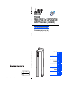
A800
INVERTER
FR-A800
FR-A806 (IP55/UL Type 12 SPECIFICATIONS)
INSTRUCTION MANUAL (HARDWARE)
High functionality and high performance
FR-A846-00023(0.4K) to 03610(132K)
INVERTER
FR-A806 INSTRUCTION MANUAL (HARDWARE)
HEAD OFFICE: TOKYO BUILDING 2-7-3, MARUNOUCHI, CHIYODA-KU, TOKYO 100-8310, JAPAN
IB(NA)-0600531ENG-D(1412)MEE Printed in Japan
MODEL
FR-A806
INSTRUCTION MANUAL (HARDWARE)
MODEL
CODE
1A2-P56
Specifications subject to change without notice.
D
INTRODUCTION
1
INSTALLATION AND WIRING
2
PRECAUTIONS FOR USE OF
THE INVERTER
3
PROTECTIVE FUNCTIONS
4
PRECAUTIONS FOR
MAINTENANCE AND
INSPECTION
SPECIFICATIONS
5
6
Thank you for choosing this Mitsubishi inverter.
This Instruction Manual describes handling and cautions about the hardware, such as installation and wiring, for the FR-A806(IP55/
UL Type12 specification product) that are different from the FR-A800.
Information about the software, such as basic operations and parameters, is described in the FR-A800 Instruction Manual (Detailed)
in the CD-ROM enclosed with the product.
In addition to this manual, please read the manuals in the enclosed CD-ROM carefully. Do not use this product until you have a full
knowledge of the equipment, safety information and instructions.
Please forward this Instruction Manual to the end user.
Electric Shock Prevention
Safety Instructions
Warning
Do not attempt to install, operate, maintain or inspect the
product until you have read through this Instruction Manual
While the inverter power is ON, do not open the front cover
(Detailed) and appended documents carefully and can use the
or the wiring cover. Do not run the inverter with the front
equipment correctly. Do not use this product until you have a
cover or the wiring cover removed. Otherwise you may
full knowledge of the equipment, safety information and
access the exposed high voltage terminals or the charging
instructions.
part of the circuitry and get an electric shock.
Installation, operation, maintenance and inspection must be
Even if power is OFF, do not remove the front cover except
performed by qualified personnel. Here, an expert means a
for wiring or periodic inspection. You may accidentally
person who meets all the conditions below.
touch the charged inverter circuits and get an electric
• A person who took a proper engineering training.
shock.
Such training may be available at your local Mitsubishi
Before wiring or inspection, LED indication of the operation
Electric office. Contact your local sales office for schedules
panel must be switched OFF. Any person who is involved in
and locations.
wiring or inspection shall wait for at least 10 minutes after
• A person who can access operating manuals for the
the power supply has been switched OFF and check that
protective devices (e.g. light curtain) connected to the safety
there are no residual voltage using a tester or the like. The
control system. A person who has read and familiarized
capacitor is charged with high voltage for some time after
power OFF, and it is dangerous.
himself/herself with the manuals.
This inverter must be earthed (grounded). Earthing
(grounding) must conform to the requirements of national
In this Instruction Manual (Detailed), the safety instruction
and local safety regulations and electrical code (NEC
levels are classified into "Warning" and "Caution"
section 250, IEC 536 class 1 and other applicable
Incorrect handling may cause hazardous
standards). A neutral-point earthed (grounded) power
Warning conditions, resulting in death or severe
supply in compliance with EN standard must be used.
injury.
Any person who is involved in wiring or inspection of this
equipment shall be fully competent to do the work.
Incorrect handling may cause hazardous
The inverter must be installed before wiring. Otherwise you
Caution conditions, resulting in medium or slight
may get an electric shock or be injured.
injury, or may cause only material
Setting dial and key operations must be performed with dry
damage.
hands to prevent an electric shock. Otherwise you may get
an electric shock.
The
Caution level may even lead to a serious
Do not subject the cables to scratches, excessive
consequence according to conditions. Both instruction levels
stress,heavy loads or pinching. Otherwise you may get an
electric shock.
must be followed because these are important to personal
Do not change the cooling fan while power is ON. It is
safety.
dangerous to change the cooling fan while power is ON.
Do not touch the printed circuit board or handle the cables
with wet hands. Otherwise you may get an electric shock.
When measuring the main circuit capacitor capacity, the DC
voltage is applied to the motor for 1s at powering OFF.
Never touch the motor terminal, etc. right after powering
OFF to prevent an electric shock.
An PM motor is a synchronous motor with highperformance magnets embedded in the rotor. Motor
terminals holds high-voltage while the motor is running
even after the inverter power is turned OFF. Before wiring
or inspection, the motor must be confirmed to be stopped.
In an application, such as fan and blower, where the motor
is driven by the load, a low-voltage manual motor starter
must be connected at the inverter's output side, and wiring
and inspection must be performed while the motor starter is
open. Otherwise you may get an electric shock.
Fire Prevention
Caution
Inverter must be installed on a nonflammable wall without
holes (so that nobody touches the inverter heatsink on the
rear side, etc.). Mounting it to or near flammable material
may cause a fire.
If the inverter has become faulty, the inverter power must be
switched OFF. A continuous flow of large current may cause
a fire.
Resistors cannot be used. Do not connect a resistor directly
to the DC terminals P/+ and N/-. Doing so could cause a fire.
Be sure to perform daily and periodic inspections as
specified in the Instruction Manual. If a product is used
without any inspection, a burst, breakage, or a fire may
occur.
Injury Prevention
Caution
The voltage applied to each terminal must be the ones
specified in the Instruction Manual. Otherwise burst,
damage, etc. may occur.
The cables must be connected to the correct terminals.
Otherwise burst, damage, etc. may occur.
The polarity (+ and -) must be correct. Otherwise burst,
damage, etc. may occur.
While power is ON or for some time after power-OFF, do not
touch the inverter as it will be extremely hot. Touching
these devices may cause a burn.
Safety Instructions
1
Additional Instructions
The following instructions must be also followed. If the product
is handled incorrectly, it may cause unexpected fault, an injury,
or an electric shock.
Caution
Transportation and Mounting
Any person who is opening a package using a sharp object,
such as a knife and cutter, must wear gloves to prevent
injuries caused by the edge of the sharp object.
The product must be transported in correct method that
corresponds to the weight. Failure to do so may lead to
injuries.
Do not stand or rest heavy objects on the product.
Do not stack the boxes containing inverters higher than the
number recommended.
When carrying the inverter, do not hold it by the front cover;
it may fall off or fail.
During installation, caution must be taken not to drop the
inverter as doing so may cause injuries.
The product must be installed on the surface that
withstands the weight of the inverter.
Do not install the product on a hot surface.
The mounting orientation of the inverter must be correct.
The inverter must be installed on a strong surface securely
with screws so that it will not drop.
Do not install or operate the inverter if it is damaged or has
parts missing.
Foreign conductive objects must be prevented from
entering the inverter. That includes screws and metal
fragments or other flammable substance such as oil.
As the inverter is a precision instrument, do not drop or
subject it to impact.
The ambient temperature must be between -10 and +40°C
(non-freezing). Otherwise the inverter may be damaged.
The ambient humidity must be 95%RH or less (noncondensing). Otherwise the inverter may be damaged.
(Refer to page 18 for details.)
The storage temperature (applicable for a short time, e.g.
during transit) must be between -20 and +65°C. Otherwise
the inverter may be damaged.
The inverter must be used indoors (without corrosive gas,
flammable gas, oil mist, dust and dirt etc.) Otherwise the
inverter may be damaged.
The inverter must be used at an altitude of 2500 m or less
above sea level, with vibration at 5.9 m/s2 or less, 10 to 55
Hz (directions of X, Y, Z axes). Otherwise the inverter may
be damaged. (Refer to page 18 for details.)
If halogen-based materials (fluorine, chlorine, bromine,
iodine, etc.) infiltrate into a Mitsubishi product, the product
will be damaged. Halogen-based materials are often
included in fumigant, which is used to sterilize or disinfest
wooden packages. When packaging, prevent residual
fumigant components from being infiltrated into Mitsubishi
products, or use an alternative sterilization or disinfection
method (heat disinfection, etc.) for packaging. Sterilization
of disinfection of wooden package should also be
performed before packaging the product.
Wiring
Do not install a power factor correction capacitor or surge
suppressor/capacitor type filter on the inverter output side.
These devices on the inverter output side may be
overheated or burn out.
The output side terminals (terminals U, V, and W) must be
connected correctly. Otherwise the motor will rotate
inversely.
PM motor terminals (U, V, W) hold high-voltage while the PM
motor is running even after the power is turned OFF. Before
wiring, the PM motor must be confirmed to be stopped.
Otherwise you may get an electric shock.
Never connect an PM motor to the commercial power
supply.
Applying the commercial power supply to input terminals
(U,V, W) of an PM motor will burn the PM motor. The PM
motor must be connected with the output terminals (U, V, W)
of the inverter.
Trial run
Before starting operation, each parameter must be
confirmed and adjusted. A failure to do so may cause some
machines to make unexpected motions.
2
2.9 m/s2 or less for the FR-A846-01800(55K) or higher.
Safety Instructions
Warning
Usage
Everyone must stay away from the equipment when the
retry function is set as it will restart suddenly after a trip.
Since pressing a key may not stop output depending
on the function setting status, separate circuit and switch
that make an emergency stop (power OFF, mechanical
brake operation for emergency stop, etc.) must be provided.
OFF status of the start signal must be confirmed before
resetting the inverter fault. Resetting inverter fault with the
start signal ON restarts the motor suddenly.
Do not use an PM motor for an application where the PM
motor is driven by its load and runs at a speed higher than
the maximum motor speed.
Use this inverter only with three-phase induction motors or
with an PM motor. Connection of any other electrical
equipment to the inverter output may damage the
equipment.
Performing pre-excitation (LX signal and X13 signal) under
torque control (Real sensorless vector control) may start
the motor running at a low speed even when the start
command (STF or STR) is not input The motor may run also
at a low speed when the speed limit value = 0 with a start
command input. It must be confirmed that the motor
running will not cause any safety problem before
performing pre-excitation.
Do not modify the equipment.
Do not perform parts removal which is not instructed in this
manual. Doing so may lead to fault or damage of the
product.
Caution
Usage
The electronic thermal relay function does not guarantee
protection of the motor from overheating. It is
recommended to install both an external thermal and PTC
thermistor for overheat protection.
Do not use a magnetic contactor on the inverter input for
frequent starting/stopping of the inverter. Otherwise the life
of the inverter decreases.
The effect of electromagnetic interference must be reduced
by using a noise filter or by other means. Otherwise nearby
electronic equipment may be affected.
Appropriate measures must be taken to suppress
harmonics. Otherwise power supply harmonics from the
inverter may heat/damage the power factor correction
capacitor and generator.
When driving a 400V class motor by the inverter, the motor
must be an insulation-enhanced motor or measures must
be taken to suppress surge voltage. Surge voltage
attributable to the wiring constants may occur at the motor
terminals, deteriorating the insulation of the motor.
When parameter clear or all parameter clear is performed,
the required parameters must be set again before starting
operations. because all parameters return to their initial
values.
The inverter can be easily set for high-speed operation.
Before changing its setting, the performances of the motor
and machine must be fully examined.
Stop status cannot be hold by the inverter's brake function.
In addition to the inverter’s brake function, a holding device
must be installed to ensure safety.
Before running an inverter which had been stored for a long
period, inspection and test operation must be performed.
Static electricity in your body must be discharged
beforeyou touch the product.
Only one PM motor can be connected to an inverter.
An PM motor must be used under PM sensorless vector
control. Do not use a synchronous motor, induction motor,
or synchronous induction motor.
Do not connect an PM motor in the induction motor control
settings (initial settings). Do not use an induction motor in
the PM sensorless vector control settings. It will cause a
failure.
In the system with an PM motor, the inverter power must be
turned ON before closing the contacts of the contactor at
the output side.
Emergency stop
A safety backup such as an emergency brake must be
provided to prevent hazardous conditions to the machine
and equipment in case of inverter failure.
When the breaker on the inverter input side trips, thewiring
must be checked for fault (short circuit), and internalparts of
the drive unit for a damage, etc. The cause of the trip must
be identified and removed before turning ON the power of
the breaker.
When a protective function activates, take an appropriate
corrective action, then reset the inverter, and resume the
operation.
Maintenance, inspection and parts replacement
Do not carry out a megger (insulation resistance) test on the
control circuit of the inverter. It will cause a failure.
Disposal
The inverter must be treated as industrial waste.
General instruction
Many of the diagrams and drawings in the Instruction
Manual show the product without a cover or partially open
for explanation. Never operate the product in this manner.
The cover must be always reinstalled and the instruction in
the Instruction Manual must be followed when operating the
product. For more details on the PM motor, refer to the
Instruction Manual of the PM motor.
Caution
Waterproof and dustproof performances
The inverter is rated with an IPX5 waterproof rating and an
IP5X dustproof rating when the operation panel (FR-DU0801), the front cover, the wiring cover, and the cable glands
are securely fixed with screws.
The items enclosed with the inverter such as the Instruction
Manual or CD are not rated with the IPX5 waterproof or IP5X
dustproof ratings.
Although the inverter is rated with the IPX5 waterproof and
IP5X dustproof ratings, it is not intended for use in water.
Also, the ratings do not guarantee protection of the inverter
from needless submersion in water or being washed under
strong running water such as a shower.
Do not pour or apply the following liquids over the inverter:
water containing soap, detergent, or bath additives; sea
water; swimming pool water; warm water; boiling water; etc.
The inverter is intended for indoor installation and not for
outdoor installation. Avoid places where the inverter is
subjected to direct sunlight, rain, sleet, snow, or freezing
temperatures.
If the operation panel (FR-DU08-01) is not installed, if the
screws of the operation panel are not tightened, or if the
operation panel is damaged or deformed, the IPX5
waterproof performance and the IP5X dustproof
performance are impaired. If any abnormalities are found on
the operation panel, ask for an inspection and repair.
If the screws of the front cover or the wiring cover are not
tightened, if any foreign matter (hair, sand grain, fiber, etc.)
is stuck between the inverter and the gasket, if the gasket is
damaged, or if the front cover or the wiring cover is
damaged or deformed, the IPX5 waterproof performance
and the IP5X dustproof performance are impaired. If any
abnormalities are found on the front cover, wiring cover, or
the gasket of the inverter, ask for an inspection and repair.
Cable glands are important components to maintain the
waterproof and dustproof performances. Be sure to use
cable glands of the recommended size and shape or
equivalent. The standard protective bushes cannot
sufficiently maintain the IPX5 waterproof performance and
the IP5X dustproof performance.
If a cable gland is damaged or deformed, the IPX5
waterproof performance and the IP5X dustproof
performance are impaired. If any abnormalities are found on
the cable glands, ask the manufacturer of the cable glands
for an inspection and repair.
To maintain the waterproof and dustproof performances of
the inverter, daily and periodic inspections are
recommended regardless of the presence or absence of
abnormalities.
IPX5 refers to protection of the inverter functions against water jets from
any direction when about 12.5-liter water is injected from a nozzle with
an inside diameter of 6.3 mm from the distance of about 3 m for at least 3
minutes.
IP5X refers to protection of the inverter functions and maintenance of
safety when the inverter is put into a stirring device containing dust of 75
µm or smaller in diameter, stirred for 8 hours, and then removed from the
device.
Water here refers to fresh water at room temperature (5 to 35°C).
Indoor here refers to the environments that are not affected by climate
conditions.
Safety Instructions
3
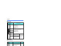
CONTENTS
1
INTRODUCTION
1.1
Product checking and accessories
8
1.2
Component names
9
1.3
About the related manuals
2
INSTALLATION AND WIRING
2.1
Peripheral devices
2.1.1
2.1.2
10
11
12
Inverter and peripheral devices ...................................................................................................................... 12
Peripheral devices.......................................................................................................................................... 14
2.2
Removal and reinstallation of the front cover
15
2.3
Installation of the inverter
18
2.3.1
2.3.2
Inverter installation environment .................................................................................................................... 18
Inverter installation ......................................................................................................................................... 20
2.4
Terminal connection diagrams
21
2.5
Main circuit terminals
25
2.5.1
2.5.2
2.5.3
2.5.4
2.5.5
2.6
2.7
2.9
47
PU connector.................................................................................................................................................. 47
USB connector ............................................................................................................................................... 48
RS-485 terminal block .................................................................................................................................... 50
Connection of motor with encoder (vector control)
2.10 Connection of stand-alone option units
2.10.1
2.10.2
2.10.3
2.10.4
44
Differences with the FR-DU08........................................................................................................................ 44
Components of the operation panel (FR-DU08-01) ....................................................................................... 45
Basic operation of the operation panel........................................................................................................... 46
Communication connectors and terminals
2.8.1
2.8.2
2.8.3
31
Details on the control circuit terminals............................................................................................................ 31
Control logic (sink/source) change ................................................................................................................. 35
Wiring of control circuit ................................................................................................................................... 37
Wiring precautions.......................................................................................................................................... 39
When supplying 24 V external power to the control circuit............................................................................. 40
Safety stop function........................................................................................................................................ 42
Operation panel (FR-DU08-01)
2.7.1
2.7.2
2.7.3
2.8
Details on the main circuit terminals............................................................................................................... 25
Terminal layout of the main circuit terminals, wiring of power supply and the motor ..................................... 25
Wiring method ................................................................................................................................................ 26
Applicable cables and the wiring length ......................................................................................................... 28
Earthing (grounding) precautions ................................................................................................................... 30
Control circuit
2.6.1
2.6.2
2.6.3
2.6.4
2.6.5
2.6.6
4
7
51
59
Connection of the brake unit (FR-BU2) .......................................................................................................... 59
Connection of the brake unit (FR-BU) ............................................................................................................ 61
Connection of the brake unit (BU type) .......................................................................................................... 62
Connection of the high power factor converter (FR-HC2) .............................................................................. 63
CONTENTS
2.10.5
2.10.6
3
Connection of the power regeneration common converter (FR-CV) ..............................................................64
Connection of the power regeneration converter (MT-RC).............................................................................65
PRECAUTIONS FOR USE OF THE INVERTER
3.1
Electro-magnetic interference (EMI) and leakage currents
3.1.1
3.1.2
3.1.3
3.2
68
Leakage currents and countermeasures ........................................................................................................68
Countermeasures against inverter-generated EMI.........................................................................................70
Built-in EMC filter ............................................................................................................................................72
Power supply harmonics
3.2.1
3.2.2
67
74
Power supply harmonics.................................................................................................................................74
Harmonic suppression guidelines in Japan ....................................................................................................75
3.3
Installation of a reactor
77
3.4
Power-OFF and magnetic contactor (MC)
78
3.5
Countermeasures against deterioration of the 400 V class motor insulation
79
3.6
Checklist before starting operation
80
3.7
Failsafe system which uses the inverter
82
4
PROTECTIVE FUNCTIONS
85
4.1
Inverter fault and alarm indications
86
4.2
Reset method for the protective functions
86
4.3
Faults history and the list of fault displays
87
5
PRECAUTIONS FOR MAINTENANCE AND
INSPECTION
5.1
Inspection item
5.1.1
5.1.2
5.1.3
5.1.4
5.1.5
5.1.6
5.1.7
5.2
89
90
Daily inspection...............................................................................................................................................90
Periodic inspection..........................................................................................................................................90
Daily and periodic inspection ..........................................................................................................................91
Checking the inverter and converter modules ................................................................................................93
Cleaning..........................................................................................................................................................93
Replacement of parts......................................................................................................................................94
Inverter replacement.....................................................................................................................................113
Measurement of main circuit voltages, currents and powers
5.2.1
5.2.2
5.2.3
5.2.4
5.2.5
5.2.6
114
Measurement of powers ...............................................................................................................................116
Measurement of voltages and use of PT ......................................................................................................116
Measurement of currents..............................................................................................................................117
Use of CT and transducer.............................................................................................................................117
Measurement of inverter input power factor .................................................................................................117
Measurement of converter output voltage (across terminals P and N).........................................................117
CONTENTS
5
5.2.7
5.2.8
5.2.9
6
Measurement of inverter output frequency................................................................................................... 118
Insulation resistance test using megger ....................................................................................................... 118
Pressure test ................................................................................................................................................ 118
SPECIFICATIONS
119
6.1
Inverter rating
120
6.2
Common specifications
121
6.3
Inverter outline dimension drawings
123
APPENDIX
127
Appendix 1 Differences and compatibility with the FR-A840 ....................................................................... 128
Appendix 2 Instructions for compliance with the EU Directives................................................................... 129
Appendix 3 Instructions for UL and cUL ...................................................................................................... 132
6
CONTENTS
1
INTRODUCTION
This contents described in this chapter must be read before using this
product.
Always read the instructions before using the equipment.
1.1
1.2
1.3
Product checking and accessories.........................................8
Component names....................................................................9
About the related manuals.......................................................10
<Abbreviations>
Operation panel .............................. Operation panel (FR-DU08-01) and LCD operation panel (FR-LU08-01)
Parameter unit ................................ Parameter unit (FR-PU07)
DU .................................................. Operation panel (FR-DU08-01)
PU .................................................. Operation panel (FR-DU08-01) and parameter unit (FR-PU07)
Inverter ........................................... Mitsubishi inverter FR-A800 series (IP55 compatible model)
Pr. .................................................. Parameter number (Number assigned to function)
PU operation .................................. Operation using the PU (operation panel / parameter unit)
External operation .......................... Operation using the control circuit signals
Combined operation ...................... Combined operation using the PU (operation panel / parameter unit) and
External operation
Mitsubishi standard motor .............. SF-JR
Mitsubishi constant-torque motor ... SF-HRCA
Vector control dedicated motor ...... SF-V5RU
Mitsubishi IPM motor ..................... MM-CF
1
<Trademarks>
• Company and product names herein are the trademarks and registered trademarks of their respective owners.
<Notes on descriptions in this Instruction Manual>
• Connection diagrams in this Instruction Manual suppose that the control logic of the input terminal is the sink
logic, unless otherwise specified. (For the control logic, refer to page 35.)
Harmonic Suppression Guidelines
All the models of the inverters used by specific consumers are covered by "the Harmonic Suppression
Guidelines for Consumers Who Receive High Voltage or Special High Voltage". (For details, refer to page 75.)
INTRODUCTION
7
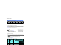
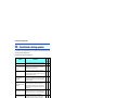
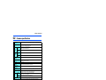
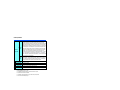
Product checking and accessories
1.1
Product checking and accessories
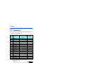
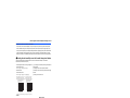
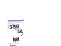
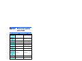
Unpack the product and check the rating plate and the capacity plate of the inverter to ensure that the model agrees with the
order and the product is intact.
Inverter model
Symbol
4
Voltage class
400V class
Symbol Structure, functionality
IP55 compatible model
6
Symbol
00023 to 03610
0.4K to 132K
Description
Symbol Type∗1
Rated inverter current
-1
FM
(SLD rated current of the
CA
-2
A800 standard model) (A)
ND rated inverter capacity (kW)
F R - A 8 4 6 - 00250 -1 -60 C3
Circuit board coating
Plated conductor
(conforming to IEC60721-3-3 3C2/3S2)
With
Not used
With
With
Symbol
-60
-06
Symbol
EMC filter
Built-in C2 filter
C2
Built-in C3 filter
C3
Rating plate
Inverter model
Input rating
Output rating
SERIAL
Manufactured
year and month
Specification differs by the type. Major differences are shown in the table below.
Type
Monitor output
Built-in EMC filter
Initial setting
Control
Rated
Pr.19 Base
logic
frequency frequency voltage
FM
(terminal FM
equipped model)
Terminal FM (pulse train output)
Terminal AM (analog voltage output
(0 to ±10 VDC))
Built-in C2 filter: ON,
Built-in C3 filter: OFF
Sink logic
60 Hz
9999 (same as the
power supply voltage)
CA
(terminal CA
equipped model)
Terminal CA (analog current output
(0 to 20 mADC))
Terminal AM (analog voltage output
(0 to ±10 VDC))
ON
Source logic
50 Hz
8888 (95% of the
power supply voltage)
NOTE
• Hereinafter, the inverter model name consists of the applicable motor capacity and the rated current value (SLD rated current
value of the A800 standard model).
(Example) FR-A846-00250(7.5K)
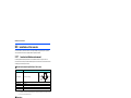
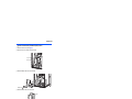
How to read the SERIAL number
Rating plate example
Symbol Year
The SERIAL consists of one symbol, two characters indicating the production
year and month, and six characters indicating the control number. The last digit
Month
Control number
of the production year is indicated as the Year, and the Month is indicated by 1
SERIAL
8
INTRODUCTION
to 9, X (October), Y (November), or Z (December.)
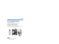
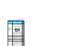
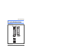
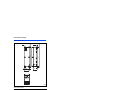
Component names
1.2
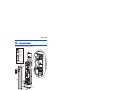
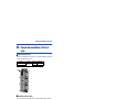
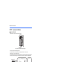
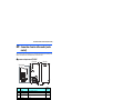
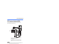
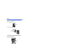
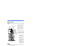
Component names
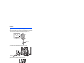
Component names are shown below. (Example: FR-A846-00250(7.5K))
Front cover for
control circuit
inspection
(q)
Front cover for
main circuit
inspection
(r)
(d)
(g)
(b)
(c)
(a)
(f)
Front cover of the
FR-A846-01800(55K) or higher
(e)
(h)
(k)
(j)
(i)
(l)
(p)
(o)
(u)
(t)
(s)
(m)
(n)
Symbol
Name
(a)
PU connector
(b)
(c)
(d)
(e)
(f)
(g)
USB A connector
USB mini B connector
RS-485 terminals
Plug-in option connector1
Plug-in option connector2
Plug-in option connector3
Refer to
page
Description
Connects the operation panel or the parameter unit. This connector also enables
the RS-485 communication.
Connects a USB memory device.
Connects a personal computer and enables communication with FR Configurator 2.
Enables RS-485, Modbus-RTU communication.
Connects a plug-in option or a communication option.
47
48
48
50
Instruction
Manual of
the option
(h)
Voltage/current input switch
Selects between voltage and current for the terminal 2 and 4 inputs.
(i)
(j)
(k)
Control circuit terminal block
EMC filter ON/OFF connector
Charge lamp
Metal fitting for earthing
(grounding)
Main circuit terminal block
Connects cables for the control circuit.
Turns ON/OFF the EMC filter.
Stays ON while the power is supplied to the main circuit.
31
72
25
Earths (grounds) the shielded wires of the encoder cable, etc.
56
(l)
(m)
(n)
(o)
(p)
(q)
(r)
(s)
(t)
(u)
Connects cables for the main circuit.
Remove the protective bushes to connect cables. (FR-A846-00470(18.5K) or
Wiring cover
lower)
Remove this cover for the installation of the product, installation of a plug-in
(communication) option, RS-485 terminal wiring, switching of the voltage/current
input switch, etc. For the FR-A846-01800(55K) or higher, the front cover for the
Front cover
control circuit inspection and the front cover for the main circuit inspection can be
individually removed.
Operation panel (FR-DU08-01) Operates and monitors the inverter.
Remove this cover for replacement of the cooling fan. (FR-A846-00250(7.5K) or
Fan cover
higher)
Cooling fan
Cools the inverter. (FR-A846-00250(7.5K) or higher)
Internal fan
Cools the inverter.
Bracket
Fixes the internal fan.
Protects the fan to avoid contacting the wiring. (FR-A846-00250(7.5K) to
Protective cover
00470(18.5K))
1
25
15
15
45
95
95
101
101
102
Refer to the FR-A800 Instruction Manual (Detailed)
INTRODUCTION
9
About the related manuals
1.3
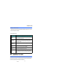
About the related manuals
The manuals related to FR-A806 are shown below.
Related manuals
Manual name
FR-A800 Instruction Manual (Detailed)
Manual number
IB-0600503ENG
FR Configurator 2 Instruction Manual
IB-0600516ENG
PLC function programming manual
IB-0600492ENG
Safety stop function instruction manual
BCN-A23228-001
10
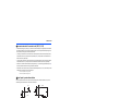
INTRODUCTION
2
INSTALLATION AND
WIRING
This chapter explains the "INSTALLATION" and the "WIRING" of this
product.
Always read the instructions before using the equipment.
2.1
2.2
2.3
2.4
2.5
2.6
2.7
2.8
2.9
2.10
Peripheral devices ....................................................................12
Removal and reinstallation of the front cover........................15
Installation of the inverter ........................................................18
Terminal connection diagrams ................................................21
Main circuit terminals ...............................................................25
Control circuit ...........................................................................31
Operation panel (FR-DU08-01).................................................44
Communication connectors and terminals ............................47
Connection of motor with encoder (vector control) ..............51
Connection of stand-alone option units .................................59
2
INSTALLATION AND WIRING
11
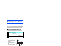
Peripheral devices
2.1
Peripheral devices
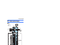
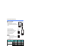
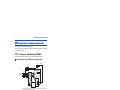
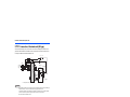
2.1.1
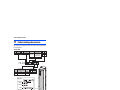
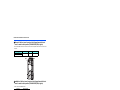
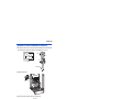
Inverter and peripheral devices
(a) Inverter
∗1
(b) Three-phase AC power supply
(k) USB connector
USB host
(A connector)
Communication
status indicator
(LED)(USB host)
(c) Moulded case circuit breaker
(MCCB) or earth leakage current
breaker (ELB), fuse
USB
USB device
(Mini B connector)
Personal computer
(FR Configurator 2)
(d) Magnetic contactor (MC)
IM connection
PM connection
U VW
U VW
R/L1 S/L2 T/L3
P/+ N/-
(e) AC reactor(FR-HAL)
Earth
(Ground)
(l) EMC filter
(ferrite core)
(FR-BSF01,
FR-BLF)
(n) Contactor
Example)
No-fuse
switch
(DSN type)
(i) Brake unit
(FR-BU2, FR-BU)
(m) Induction motor
Earth (Ground)
P/+ PR
(o) PM motor
(MM-CF)
P/+
PR
(f) High power factor
converter
(FR-HC2)
(g) Power regeneration
common converter
(FR-CV)
(h) Power regeneration
converter (MT-RC)
(j) Resistor unit
(FR-BR, MT-BR5)
Earth (Ground)
: Install these options as required.
The figure shows the area when the front cover is removed.
NOTE
• To prevent an electric shock, always earth (ground) the motor and inverter.
• Do not install a power factor correction capacitor or surge suppressor or capacitor type filter on the inverter's output side.
Doing so will cause the inverter to trip or the capacitor and surge suppressor to be damaged. If any of the above devices is
connected, immediately remove it. When installing a molded case circuit breaker on the output side of the inverter, contact
the manufacturer of the molded case circuit breaker.
• Electromagnetic wave interference
The input/output (main circuit) of the inverter includes high frequency components, which may interfere with the
communication devices (such as AM radios) used near the inverter. In this case, activating the EMC filter may minimize
interference. (Refer to page 72.)
• For details of options and peripheral devices, refer to the respective Instruction Manual.
• A PM motor cannot be driven by the commercial power supply.
• A PM motor is a motor with permanent magnets embedded inside. High voltage is generated at the motor terminals while the
motor is running. Before closing the contactor at the output side, make sure that the inverter power is ON and the motor is
stopped.
12
INSTALLATION AND WIRING
Peripheral devices
Symbol
Name
Overview
Refer
to page
(a)
Inverter (FR-A806)
The life of the inverter is influenced by the ambient temperature.
The ambient temperature should be as low as possible within the
permissible range.
Incorrect wiring may lead to damage of the inverter. The control signal
lines must be kept fully away from the main circuit lines to protect them
from noise.
The built-in EMC filter can reduce the noise.
In this inverter, a DC reactor and common mode choke are built in to
suppress harmonics and to improve the power factor.
(b)
Three-phase AC power supply
Must be within the permissible power supply specifications of the inverter.
120
(c)
Molded case circuit breaker (MCCB),
earth leakage circuit breaker (ELB), or
fuse
Must be selected carefully since an inrush current flows in the inverter at
power ON.
14
(d)
Magnetic contactor (MC)
Install this to ensure safety.
Do not use this to start and stop the inverter. Doing so will shorten the life
of the inverter.
78
(e)
AC reactor (FR-HAL)
Install this to suppress harmonics and to improve the power factor.
An AC reactor (FR-HAL) (option) is required when installing the inverter
near a large power supply system (1000 kVA or more). Under such
condition, the inverter may be damaged if you do not use a reactor.
Select a reactor according to the applied motor capacity.
77
(f)
High power factor converter (FR-HC2)
Suppresses the power supply harmonics significantly. Install this as
required.
63
(g)
Power regeneration common converter
(FR-CV)
(h)
Power regeneration converter
(MT-RC)
(i)
Brake unit (FR-BU2, FR-BU, BU)
(j)
Resistor unit (FR-BR, MT-BR5)
(k)
18
21
72
64
Provides a large braking capability. Install this as required.
65
Allows the inverter to provide the optimal regenerative braking capability.
Install this as required.
59
USB connection
A USB (Ver. 1.1) cable connects the inverter with a personal computer.
A USB memory device enables parameter copies and the trace function.
48
(l)
Noise filter
(FR-BSF01, FR-BLF)
Install this to reduce the electromagnetic noise generated from the
inverter. The noise filter is effective in the range from about 0.5 MHz to 5
MHz.
A wire should be wound four turns at maximum.
70
(m)
Induction motor
Connect a squirrel-cage induction motor.
―
(n)
Contactor
Example) No-fuse switch (DSN type)
Connect this for an application where a PM motor is driven by the load
even while the inverter power is OFF. Do not open or close the contactor
while the inverter is running (outputting).
―
(o)
PM motor
When PM sensorless vector control is selected, a PM motor can be
driven.
―
Compatible with the FR-A846-01800(55K) or lower.
Compatible with the FR-A846-02160(75K) or higher.
2
INSTALLATION AND WIRING
13
Peripheral devices
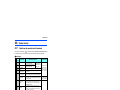
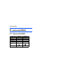
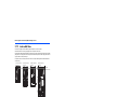
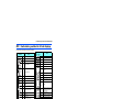
2.1.2
Peripheral devices
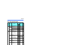
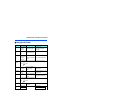
Check the model of the inverter you purchased. Appropriate peripheral devices must be selected according to the capacity.
Refer to the table below to prepare appropriate peripheral devices.
Motor output
(kW)
Applicable inverter model
Molded case circuit breaker (MCCB)
or earth leakage circuit breaker (ELB)
(NF, NV type)
Input-side magnetic
contactor
0.4
FR-A846-00023(0.4K)
5A
S-T10
0.75
FR-A846-00038(0.75K)
5A
S-T10
1.5
FR-A846-00052(1.5K)
10A
S-T10
2.2
FR-A846-00083(2.2K)
10A
S-T10
3.7
FR-A846-00126(3.7K)
15A
S-T10
5.5
FR-A846-00170(5.5K)
20A
S-T12
7.5
FR-A846-00250(7.5K)
30A
S-T21
11
FR-A846-00310(11K)
40A
S-T21
15
FR-A846-00380(15K)
50A
S-T21
18.5
FR-A846-00470(18.5K)
60A
S-N25
22
FR-A846-00620(22K)
75A
S-N25
30
FR-A846-00770(30K)
100A
S-N50
37
FR-A846-00930(37K)
125A
S-N50
45
FR-A846-01160(45K)
150A
S-N65
55
FR-A846-01800(55K)
175A
S-N80
75
FR-A846-02160(75K)
225A
S-N95
90
FR-A846-02600(90K)
225A
S-N150
110
FR-A846-03250(110K)
225A
S-N180
132
FR-A846-03610(132K)
400A
S-N220
Assumes the use of a Mitsubishi 4-pole standard motor with the power supply voltage of 400 VAC 50 Hz.
Select an MCCB according to the power supply capacity.
Install one MCCB per inverter.
For the use in the United States or Canada, provide the appropriate UL and cUL listed fuse or UL489
molded case
circuit breaker (MCCB) that is suitable for branch circuit protection. (Refer to page 132.)
MCCB
INV
M
MCCB
INV
M
Magnetic contactor is selected based on the AC-1 class. The electrical durability of magnetic contactor is 500,000 times. When the magnetic
contactor is used for emergency stops during motor driving, the electrical durability is 25 times.
If using an MC for emergency stop during motor driving, select an MC regarding the drive unit input side current as JEM1038-AC-3 class
rated current. When providing an MC on the inverter output side for switching to commercial power supply during general-purpose motor
operation, select an MC regarding the rated motor current as JEM1038-AC-3 class rated current.
NOTE
• When the inverter capacity is larger than the motor capacity, select an MCCB and a magnetic contactor according to the
inverter model, and select cables and reactors according to the motor output.
• When the breaker on the inverter's input side trips, check for the wiring fault (short circuit), damage to internal parts of the
inverter etc. The cause of the trip must be identified and removed before turning ON the power of the breaker.
14
INSTALLATION AND WIRING
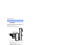
Removal and reinstallation of the front cover
2.2
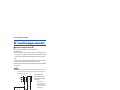
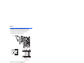
Removal and reinstallation of the front
cover
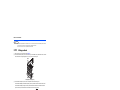
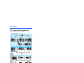
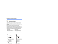
Removal of the front cover
• Remove the front cover installation screws to remove the front cover. (For the FR-A846-00620(22K) to 01160(45K), remove
the operation panel before removing the front cover.)
Inverter
Screw type
FR-A846-00470(18.5K) or lower
FR-A846-00620(22K) or higher
Screw size
Hexalobular screw
Loosen
Screwdriver size
M4
T20
M5
T25
Loosen
Reinstallation of the front cover
• Fix the front cover with the front cover installation screws. (For the FR-A846-00620(22K) to 01160(45K), install the front
cover while the operation panel is removed.)
Inverter
Tightening torque
FR-A846-00470(18.5K) or lower
1.4 to 1.9 N·m
FR-A846-00620(22K) or higher
2.8 to 3.6 N·m
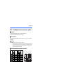
Tighten the front cover installation screws in the numerical order in the figure shown below.
FR-A846-00023(0.4K) to 00170(5.5K),
FR-A846-00250(7.5K) to 00470(18.5K)
FR-A846-00620(22K) to 01160(45K)
Tighten
(1)
Tighten
(3)
(1)
Tighten
Tighten
(1)
(3)
Tighten
Tighten
(5)
(5)
(3)
FR-A846-01800(55K) to 03610(132K)
(8)
(5)
(8)
(6)
(9)
(7)
(6)
(4)
(2)
(10)
(7)
(6)
(4)
(2)
(4)
(2)
INSTALLATION AND WIRING
15
2
Removal and reinstallation of the front cover
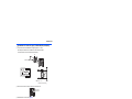
Removal of the front cover for control circuit inspection and the front
cover for main circuit inspection (FR-A846-01800(55K) or higher)
• Remove the installation screws to remove the front cover for control circuit inspection and/or the front cover for main circuit
inspection.
Front cover
For control circuit inspection
For main circuit inspection
Screw type
Screw size
Hexalobular screw
M5
Screwdriver size
T25
Loosen
Loosen
Installation of the front cover for control circuit inspection and the front
cover for main circuit inspection (FR-A846-01800(55K) or higher)
• Fix the covers with the installation screws.
Front cover
For control circuit inspection
For main circuit inspection
Tightening torque
2.8 to 3.6 N·m
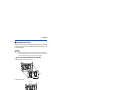
To install the front cover for control circuit inspection and/or the front cover for main circuit inspection, tighten the installation
screws in the numerical order in the figure shown below.
Tighten
(1)
(4)
Tighten
16
INSTALLATION AND WIRING
(1)
(3)
Tighten
(2)
(3)
(5)
(6)
(4)
(2)
Tighten
Removal and reinstallation of the front cover
NOTE
• When installing the front cover for the FR-A846-00470(18.5K) or lower, fit the connector of the operation panel securely along
the guides of the PU connector. Otherwise, the operation panel connection connector or the PU connector may be damaged.
• For the FR-A846-00620(22K) to 03610(132K), before removing/installing the front cover, always remove the operation panel.
Otherwise, the operation panel connection connector or the PU connector may be damaged.
• When removing/installing the front cover of the FR-A846-00620(22K) to 01160(45K), always hold the front cover at the flange
sections. Otherwise, the front cover may fall off, resulting in damage or injuries.
Flange
• Before installing the front cover, check the waterproof gasket to make sure that it is not damaged. If it is damaged, contact the
nearest Mitsubishi FA center.
• Securely install the front cover to fit the waterproof gasket closely. Do not let the waterproof gasket get stuck between the
front cover edge and the inverter. Otherwise, water may get into the inverter. Also, do not let any foreign matter get stuck
between the waterproof gasket and the front cover.
• Keep the waterproof gasket of the inverter clean. Otherwise, water may get into the inverter. If there is any dirt on the gasket,
make sure to remove it.
• Fully make sure that the front cover is installed securely. Always tighten the mounting screws of the front cover.
2
INSTALLATION AND WIRING
17
Installation of the inverter
2.3
Installation of the inverter
An inverter unit uses many semiconductor devices. To ensure higher reliability and long period of operation, operate the
inverter in the ambient environment that completely satisfies the equipment specifications.
2.3.1
Inverter installation environment
The following table lists the standard specifications of the inverter installation environment. Using the inverter in an
environment that does not satisfy the conditions deteriorates the performance, shortens the life, and causes a failure. Refer to
the following points, and take adequate measures.
Standard environmental specifications of the inverter
Item
Description
Measurement
position
Ambient temperature
-10 to +40°C (non-freezing)
5cm
(1.97inches)
Inverter
Measurement
position
Ambient humidity
5cm
(1.97inches)
5cm
(1.97inches)
95% RH or less (non-condensing)
Storage temperature
-20 to +65°C
Atmosphere
Indoors (free from corrosive gas, flammable gas, oil mist, dust and dirt)
Altitude
Maximum 1,000 m above sea level.
Vibration
5.9 m/s2 or less at 10 to 55 Hz (directions of X, Y, Z axes)
Temperature applicable for a short time, e.g. in transit.
For the installation at an altitude above 1,000 m (3280.80 feet) up to 2,500 m (8202 feet), derate the rated current 3% per 500 m (1640.40 feet).
2.9 m/s2 or less for the FR-A846-01800(55K) or higher.
Temperature
The permissible ambient temperature of the inverter is between -10°C and +40°C. Always operate the inverter within this
temperature range. Operation outside this range will considerably shorten the service lives of the semiconductors, parts,
capacitors and others. Take the following measures to keep the ambient temperature of the inverter within the specified range.
(a) Measures against high temperature
• Ventilate the room.
• Install the inverter in an air-conditioned electric chamber.
• Block direct sunlight.
• Provide a shield or similar plate to avoid direct exposure to the radiated heat and wind of a heat source.
• Ventilate the area around the inverter well.
(b) Measures against low temperature
• Provide a heater around the inverter.
• Do not power OFF the inverter. (Keep the start signal of the inverter OFF.)
(c) Sudden temperature changes
• Select an installation place where temperature does not change suddenly.
• Avoid installing the inverter near the air outlet of an air conditioner.
• If temperature changes are caused by opening/closing of a door, install the inverter away from the door.
18
INSTALLATION AND WIRING
Installation of the inverter
Humidity
Operate the inverter within the ambient air humidity of usually 45 to 90%. Too high humidity will pose problems of reduced
insulation and metal corrosion. On the other hand, too low humidity may cause a spatial electrical breakdown.
The insulation distance defined in JEM1103 "Control Equipment Insulator" is humidity of 45 to 85%.
(a) Measures against high humidity
• Provide dry air into the room from outside.
• Use a dehumidifier.
(b) Measures against low humidity
Air with proper humidity can be blown into the room from outside. Also when installing or inspecting the unit, discharge your
body (static electricity) beforehand, and keep your body away from the parts and patterns.
(c) Measures against condensation
Condensation may occur if frequent operation stops change the in-room temperature suddenly or if the outside air
temperature changes suddenly.
Condensation causes such faults as reduced insulation and corrosion.
• Take the measures against high humidity in (a).
• Do not power OFF the inverter. (Keep the start signal of the inverter OFF.)
Dust, dirt, oil mist
Dust and dirt will cause faults such as poor contacts, reduction in insulation and cooling effect due to accumulation of
moisture-absorbed dust and dirt, and equipment internal temperature rise due to a clogged ventilation filter in the room where
the equipment is installed. In an atmosphere where conductive powder floats, dust and dirt will cause such faults as
malfunction, deteriorated insulation and short circuit in a short time.
Since oil mist will cause similar conditions, it is necessary to take adequate measures.
Countermeasure
• Purge air.
Pump clean air from outside to make the in-enclosure air pressure higher than the outside air pressure.
Corrosive gas, salt damage
If the inverter is exposed to corrosive gas or to salt near a beach, the printed board patterns and parts will corrode or the
relays and switches will result in poor contact.
In such a place, take the countermeasures described in "Dust, dirt, oil mist" above.
Explosive, flammable gases
As the inverter is non-explosion proof, it must be contained in an explosion-proof enclosure. In places where explosion may
be caused by explosive gas, dust or dirt, an enclosure cannot be used unless it structurally complies with the guidelines and
has passed the specified tests. This makes the enclosure itself expensive (including the test charges). The best way is to
2
avoid installation in such places and install the inverter in a non-hazardous place.
High altitude
Use the inverter at an altitude of within 1000 m. For the installation at an altitude above 1,000 m (3280.80 feet) up to 2,500 m
(8202 feet), derate the rated current 3% per 500 m (1640.40 feet).
If it is used at a higher place, it is likely that thin air will reduce the cooling effect and low air pressure will deteriorate dielectric
strength.
Vibration, impact
The vibration resistance of the inverter is up to 5.9 m/s2 (2.9 m/s2 or less for the FR-A846-01800(55K) or higher) at 10 to 55
Hz frequency and 1 mm amplitude for the directions of X, Y, Z axes. Applying vibration and impacts for a long time may loosen
the structures and cause poor contacts of connectors, even if those vibration and impacts are within the specified values.
Especially when impacts are applied repeatedly, caution must be taken because such impacts may break the installation feet.
Countermeasure
• Strengthen the structure to prevent the installation surface from resonance.
• Install the inverter away from the sources of the vibration.
INSTALLATION AND WIRING
19
Installation of the inverter
2.3.2
Inverter installation
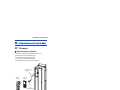
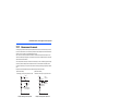
Inverter placement
• Install the inverter on a strong flat surface securely with screws.
Fix six positions for the FR-A846-01800(55K) or higher.
• Leave enough clearances and take cooling measures.
• Avoid places where the inverter is subjected to direct sunlight, high temperature and high humidity.
• Install the inverter on a nonflammable wall surface.
• For heat dissipation and maintenance, keep clearance between the inverter and the other devices. The clearance below
the inverter is required as a wiring space, and the clearance above the inverter is required as a heat dissipation space.
Clearances (side)
Clearances (front)
FR-A846-01800(55K) or lower
FR-A846-02160(75K) or higher
20cm
(7.88inches)
or more
10cm
(3.94inches)
or more
Vertical
5cm
(1.97
inches)
or more
5cm
(1.97
inches)
or more
10cm
(3.94
inches)
or more
10cm
(3.94
inches)
or more
5cm
(1.97
inches)
or more Inverter
Allow clearance.
10cm
(3.94inches)
or more
20cm
(7.88inches)
or more
For the FR-A846-00126(3.7K) or lower, allow 1 cm (0.39 inches) or more clearance.
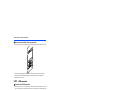
Installation orientation of the inverter
Install the inverter on a wall as specified. Do not mount it horizontally or in any other way.
Above the inverter
Heat is blown up from inside the inverter by the small fan built in the unit. Any equipment placed above the inverter should be
heat resistant.
20
INSTALLATION AND WIRING
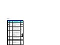
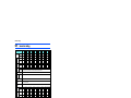
Terminal connection diagrams
2.4
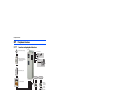
Terminal connection diagrams
FM type
Sink logic
Main circuit terminal
Brake unit
(Option)
Control circuit terminal
Jumper
P1
MCCB
P/+
R/L1
S/L2
T/L3
Three-phase
AC power
supply
ON
EMC filter
ON/OFF
connecter ∗9
Earth (Ground)
Control circuit
Control input signals
(No voltage input allowed)∗1
Forward rotation start
Reverse rotation start
Start self-holding selection
Multi-speed Middle speed
selection
Low speed
Relay output∗5
STF
C1
STR
B1
STP(STOP)
A1
RH
C2
RM
B2
High speed
JOG ∗2
SU
MRS
IPF
RES
OL
AU
FU
CS
SD
24VDC power supply
(Common for external power supply transistor)
24V external power
supply input
Common terminal
2
1
DC0 to ±10V Initial value
1 DC0 to ±5V selectable
∗3
Auxiliary (+)
(-)
input
Terminal 4 input (+)
(Current input) (-)
4
Connector for plug-in option connection
DC4 to 20mA Initial value
DC0 to 5V selectable ∗3
DC0 to 10V
connector 1 connector 2
connector 3
Shorting
wire
Open collector output∗6
Up to frequency
Instantaneous
power failure
Overload
Open collector output common
Sink/source common
24V
∗3 Voltage/current
input switch
10E(+10V) ON
OFF
10(+5V)
2 4
DC0 to 5V Initial value
2 DC0 to 10V selectable
∗3
DC0 to 20mA
5
(Analog common)
3
Running
PC
+24
SD
Frequency setting signals (Analog)
Relay output 2
Frequency detection
SE
SINK
Reset
Terminal 4 input selection
(Current input selection)
Selection of automatic restart
after instantaneous
power failure
Contact input common
SOURCE
Output stop
RUN
RT
Second function selection
Relay output 1
(Fault output)
A2
RL
Jog operation
PU
connector
F/C
USB A
(FM)
connector ∗7
SD
USB
mini B
AM
connector
5
PC
Safety stop input (Channel 1)
Safety stop input (Channel 2)
S2
SIC
TXDRXD+
RXDGND
(SG)
SD
Terminating
VCC
resistor
Output shutoff
circuit
+
-
Calibration
resistor ∗8
(+)
(-)
So
SOC
Indicator
(Frequency meter, etc.)
Moving-coil type
1mA full-scale
2
Analog signal output
(0 to ±10VDC)
RS-485 terminals
TXD+
24V
S1
Safety stop input common
M
Main circuit
Earth
(Ground)
Safety stop signal
Motor
U
V
W
Inrush current
limit circuit
OFF
Frequency setting
potentiometer
1/2W1kΩ∗4
N/-
Reactor
MC
Data
transmission
Data
reception
GND
5V
(Permissible load current 100mA)
Safety monitor output
Safety monitor output common
INSTALLATION AND WIRING
21
Terminal connection diagrams
The function of these terminals can be changed with the input terminal assignment (Pr.178 to Pr.189). (Refer to the FR-A800 Instruction Manual
(Detailed).)
Terminal JOG is also used as a pulse train input terminal. Use Pr.291 to choose JOG or pulse.
Terminal input specifications can be changed by analog input specification switchover (Pr.73, Pr.267). To input a voltage, set the voltage/current
input switch OFF. To input a current, set the voltage/current input switch ON. Terminals 10 and 2 are also used as a PTC input terminal. (Pr.561)
(Refer to the FR-A800 Instruction Manual (Detailed).)
It is recommended to use 2 W 1 k when the frequency setting signal is changed frequently.
The function of these terminals can be changed with the output terminal assignment (Pr.195, Pr.196). (Refer to the FR-A800 Instruction Manual
(Detailed).)
The function of these terminals can be changed with the output terminal assignment (Pr.190 to Pr.194). (Refer to the FR-A800 Instruction
Manual (Detailed).)
The terminal FM can be used to output pulse trains as open collector output by setting Pr.291.
Not required when calibrating the scale with the operation panel.
Do not change the initially set ON (enabled) position of the EMC filter ON/OFF connector in the case of the inverter with a built-in C2 filter. The
Class C2 compatibility condition is not satisfied with the EMC filter OFF. The FR-A846-00250(7.5K)-C2 to FR-A846-00470(18.5K)-C2 are not
provided with the EMC filter ON/OFF connector. The EMC filter is always ON.
NOTE
• To prevent a malfunction due to noise, keep the signal cables 10 cm (3.94 inches) or more away from the power cables. Also,
separate the main circuit cables at the input side from the main circuit cables at the output side.
• After wiring, wire offcuts must not be left in the inverter.
Wire offcuts can cause an alarm, failure or malfunction. Always keep the inverter clean.
When drilling mounting holes in a wall or the side of the enclosure etc., take caution not to allow chips and other foreign
matters to enter the inverter.
• Set the voltage/current input switch correctly. Incorrect setting may cause a fault, failure or malfunction.
22
INSTALLATION AND WIRING
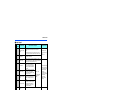
Terminal connection diagrams
CA type
Source logic
Main circuit terminal
Brake unit
(Option)
Control circuit terminal
Jumper
P1
MC
MCCB
P/+
N/-
Reactor
R/L1
S/L2
T/L3
Three-phase
AC power
supply
ON
OFF
Earth (Ground)
Control circuit
Control input signals
(No voltage input allowed)∗1
Forward rotation start
Reverse rotation start
Start self-holding selection
Multi-speed Middle speed
selection
Low speed
Relay output∗5
STF
C1
STR
B1
STP(STOP)
A1
RH
C2
RM
B2
High speed
JOG ∗2
RUN
SU
MRS
IPF
RES
OL
Terminal 4 input selection
(Current input selection)
AU
FU
Selection of automatic restart
after instantaneous power failure
CS
Common for external power
supply transistor
SD
Contact input common
24VDC power supply
PC
24V external power
supply input
Common terminal
+24
Reset
∗3 Voltage/current
input switch
10E(+10V) ON
OFF
10(+5V)
2 4
DC0 to 5V Initial value
2 DC0 to 10V selectable
∗3
DC0 to 20mA
5
(Analog common)
3
2
1
DC0 to ±10V Initial value
1 DC0 to ±5V selectable
∗3
Auxiliary (+)
(-)
input
Terminal 4 input (+)
(Current input) (-)
4
Connector for plug-in option connection
DC4 to 20mA Initial value
DC0 to 5V selectable ∗3
DC0 to 10V
connector 1 connector 2
connector 3
Shorting
wire
PC
Safety stop input (Channel 1)
Safety stop input (Channel 2)
S2
Safety stop input common
SIC
SD
Open collector output∗6
Up to frequency
Instantaneous
power failure
Overload
Open collector output common
Sink/source common
PU
connector
F/C
(CA)
USB A
connector
USB
mini B
connector
AM
5
(+)
(-)
Analog current output
(0 to 20mADC)
Analog signal output
(DC0 to ±10V)
TXDRXD+
RXDGND
(SG)
So
SOC
2
RS-485 terminals
TXD+
Terminating
VCC
resistor
Output shutoff
circuit
(+)
(-)
24V
S1
Running
24V
SD
Frequency setting signals (Analog)
Relay output 2
Frequency detection
SE
SINK
Output stop
SOURCE
RT
Second function selection
Relay output 1
(Fault output)
A2
RL
Jog operation
Safety stop signal
M
EMC filter
ON/OFF
connecter ∗7
Main circuit
Earth
(Ground)
Frequency setting
potentiometer
1/2W1kΩ∗4
Motor
U
V
W
Inrush current
limit circuit
Data
transmission
Data
reception
GND
5V
(Permissible load current 100mA)
Safety monitor output
Safety monitor output common
INSTALLATION AND WIRING
23
Terminal connection diagrams
The function of these terminals can be changed with the input terminal assignment (Pr.178 to Pr.189). (Refer to the FR-A800 Instruction Manual
(Detailed).)
Terminal JOG is also used as a pulse train input terminal. Use Pr.291 to choose JOG or pulse.
Terminal input specifications can be changed by analog input specification switchover (Pr.73, Pr.267). To input a voltage, set the voltage/current
input switch OFF. To input a current, set the voltage/current input switch ON. Terminals 10 and 2 are also used as a PTC input terminal. (Pr.561)
(Refer to the FR-A800 Instruction Manual (Detailed).)
It is recommended to use 2 W 1 k when the frequency setting signal is changed frequently.
The function of these terminals can be changed with the output terminal assignment (Pr.195, Pr.196). (Refer to the FR-A800 Instruction Manual
(Detailed).)
The function of these terminals can be changed with the output terminal assignment (Pr.190 to Pr.194). (Refer to the FR-A800 Instruction
Manual (Detailed).)
Do not change the initially set ON (enabled) position of the EMC filter ON/OFF connector in the case of the inverter with a built-in C2 filter. The
Class C2 compatibility condition is not satisfied with the EMC filter OFF. The FR-A846-00250(7.5K)-C2 to FR-A846-00470(18.5K)-C2 are not
provided with the EMC filter ON/OFF connector. The EMC filter is always ON.
NOTE
• To prevent a malfunction due to noise, keep the signal cables 10 cm (3.94 inches) or more away from the power cables. Also,
separate the main circuit cables at the input side from the main circuit cables at the output side.
• After wiring, wire offcuts must not be left in the inverter.
Wire offcuts can cause an alarm, failure or malfunction. Always keep the inverter clean.
When drilling mounting holes in a wall or the side of the enclosure etc., take caution not to allow chips and other foreign
matters to enter the inverter.
• Set the voltage/current input switch correctly. Incorrect setting may cause a fault, failure or malfunction.
24
INSTALLATION AND WIRING
Main circuit terminals
2.5
Main circuit terminals
2.5.1
Details on the main circuit terminals
Terminal
symbol
Terminal name
R/L1,
S/L2,
T/L3
AC power input
U, V, W
Refer to
page
Terminal function description
Connect these terminals to the commercial power supply.
Do not connect anything to these terminals when using the high power factor
converter (FR-HC2) or the power regeneration common converter (FR-CV).
—
Inverter output
Connect these terminals to a three-phase squirrel cage motor or a PM motor.
—
P/+, N/-
Brake unit connection
Connect the brake unit (FR-BU2, FR-BU, BU), power regeneration common
converter (FR-CV), power regeneration converter (MT-RC), high power factor
converter (FR-HC2), or DC power supply (under DC feeding mode).
59
P/+, P1
—
The jumper across terminals P/+ and P1 should not be removed.
—
Earth (ground)
For earthing (grounding) the inverter chassis. This must be earthed (grounded).
30
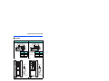
2.5.2
Terminal layout of the main circuit terminals,
wiring of power supply and the motor
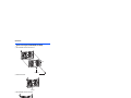
FR-A846-00023(0.4K) to FR-A846-00170(5.5K)
FR-A846-00250(7.5K) to FR-A846-00470(18.5K)
Charge lamp
Charge lamp
Jumper
P/+
N/-
Jumper
R/L1 S/L2 T/L3
R/L1 S/L2 T/L3 N/P/+
M
Power supply
Motor
M
Power supply
FR-A846-00620(22K) to FR-A846-01160(45K)
Motor
FR-A846-01800(55K) to FR-A846-03610(132K)
2
Charge lamp
Charge lamp
Jumper
R/L1 S/L2 T/L3
R/L1 S/L2 T/L3 N/P/+
P/+
N/-
M
Power supply
Motor
M
Power supply
Motor
Jumper
INSTALLATION AND WIRING
25
Main circuit terminals
NOTE
• Make sure the power cables are connected to the R/L1, S/L2, and T/L3. (Phase need not be matched.) Never connect the
power cable to the U, V, and W of the inverter. Doing so will damage the inverter.
• Connect the motor to U, V, and W. The phase need to be matched.
2.5.3
Wiring method
(1) Remove the front cover of the inverter. (Refer to page 15)
(2) For the FR-A846-00470(18.5K) or lower, remove the wiring cover installation screws (hexalobular screws, screw size:
M5, screwdriver size: T20, tightening torque: 2.8 to 3.7 N·m) to remove the wiring cover.
Loosen
Loosen
Example of the FR-A846-00250(7.5K)
(3) For the FR-A846-00470(18.5K) or lower, remove the protective bushes from the wiring cover.
For the FR-A846-00620(22K) to FR-A846-01160(45K), remove the protective bushes from the bottom of the inverter.
For the FR-A846-01800(55K) or higher, remove the protective bushes from the bottom and the side of the inverter.
(Do not remove the protective bushes from the holes that are not used for wiring of cables.)
FR-A846-00023(0.4K) to FR-A846-00470(18.5K)
FR-A846-00620(22K) to FR-A846-01160(45K)
FR-A846-01800(55K) to FR-A846-03610(132K)
NOTE
• For the FR-A846-01800(55K) or higher, do not remove the screws on the bottom of the inverter. The IPX5 waterproof
performance may be impaired.
26
INSTALLATION AND WIRING
Main circuit terminals
(4) Fix the cables using a cable gland and a nut, according to the diameter of the holes.
For the details such as hole diameters and recommended cable glands, refer to the following table.
FR-A846-00023(0.4K) to 00170(5.5K)
(a)
(a)
FR-A846-00250(7.5K) to 00470(18.5K)
(a)
(a)
(a)
(a)
FR-A846-00620(22K) to 01160(45K)
(a)
(a)
(c)
(a)
(b)
(b)
(c)
(b)
(d)
(a)
(c)
(a)
(a)
(d)
(d)
FR-A846-01800(55K) to 03610(132K)
(a)
(a)
(a)
(a)
(b)
(c)
(d)
Inverter capacity
FR-A846-00023(0.4K) to
00170(5.5K)
FR-A846-00250(7.5K) to
00470(18.5K)
FR-A846-00620(22K) to
01160(45K)
FR-A846-01800(55K) to
03610(132K)
Symbol
Recommended
layout example
(a)
Control circuit wiring
(b)
AC power input wiring
(c)
Brake unit connection wiring
(d)
Inverter output wiring
(a)
Control circuit wiring
(b)
AC power input wiring
(c)
Brake unit connection wiring
(d)
Inverter output wiring
(a)
Control circuit wiring
(b)
AC power input wiring
(c)
Brake unit connection wiring
(d)
Inverter output wiring
(a)
Control circuit wiring
(b)
AC power input wiring
(c)
Brake unit connection wiring
(d)
Inverter output wiring
Hole
diameter
(mm)
Recommended
cable gland
SKINTOP MS-SC-M
(Manufactured by
LAPP KABEL)
Recommended
nut
SKINDICHT SM-M
(Manufactured by
LAPP KABEL)
20.3
53112630
52103020
32.3
53112677
52103040
20.3
53112630
52103020
40.4
53112660
52103050
20.2
53112630
52103020
63
53112680
52103070
20.2
53112020
52103020
63
53112681
52103070
2
(5) For the FR-A846-00470(18.5K) or lower, install the wiring cover.
(6) Connect cables to the terminals of the inverter.
(7) Install the front cover to the inverter. (Refer to page 15)
CAUTION
Always use a waterproof cable gland (IP55 or higher) for the hole from which the protective bush is
removed because water may get into the inverter.
INSTALLATION AND WIRING
27
Main circuit terminals
2.5.4
Applicable cables and the wiring length
Select a recommended cable size to ensure that the voltage drop will be 2% or less.
If the wiring distance is long between the inverter and motor, the voltage drop in the main circuit wires will cause the motor
torque to decrease especially at a low speed.
The following table indicates a selection example for the wiring length of 20 m.
• 400 V class (440 V input power supply (with 150% rated current for one minute))
Cable gauge
Crimping
Applicable
2
Terminal Tightening terminal
AWG/MCM PVC cables, etc. (mm2)
HIV cables, etc. (mm )
inverter
screw
torque R/L1,
R/L1,
Earthing R/L1,
R/L1,
Earthing
model
U, V,
U, V, P/+,
U, V,
U, V,
size
N·m
S/L2,
S/L2,
(grounding)
S/L2,
S/L2,
(grounding)
FR-A846-[ ]
W
W
P1
W
W
T/L3
T/L3
cable
T/L3
T/L3
cable
00023(0.4K) to
M4
00126(3.7K)
1.5
2-4
2-4
2
2
2
2
14
14
2.5
2.5
2.5
00170(5.5K)
M4
1.5
2-4
2-4
2
2
3.5
3.5
12
14
2.5
2.5
4
00250(7.5K)
M6
4.4
5.5-6
5.5-6
3.5
3.5
3.5
3.5
12
12
4
4
4
00310(11K)
M6
4.4
5.5-6
5.5-6
5.5
5.5
5.5
5.5
10
10
6
6
10
00380(15K)
M6
4.4
8-6
8-6
8
8
8
5.5
8
8
10
10
10
00470(18.5K) M6
4.4
14-6
8-6
14
8
14
8
6
8
16
10
16
00620(22K)
M6
4.4
14-6
14-6
14
14
22
14
6
6
16
16
16
00770(30K)
M6
4.4
22-6
22-6
22
22
22
14
4
4
25
25
16
00930(37K)
M8
7.8
22-8
22-8
22
22
22
14
4
4
25
25
16
01160(45K)
M8
7.8
38-8
38-8
38
38
38
22
1
2
50
50
25
01800(55K)
M10
14.7
60-10 60-10 60
60
60
22
1/0
1/0
50
50
25
02160(75K)
M10
14.7
60-10 60-10 60
60
60
22
1/0
1/0
50
50
25
02600(90K)
M10
14.7
60-10 60-10 60
80
80
22
3/0
3/0
50
50
25
03250(110K)
M10
14.7
80-10 80-10 80
60
80
38
3/0
3/0
70
70
35
M10
14.7
100-10 100-10 100
100
100
38
4/0
4/0
95
95
50
03610(132K)
For the FR-A846-01800(55K) or lower, it is the gauge of a cable with the continuous maximum permissible temperature of 75°C (HIV cable (600
V grade heat-resistant PVC insulated wire), etc.). It assumes a surrounding air temperature of 50°C or lower and the wiring distance of 20 m or
shorter.
For the FR-A846-02160(75K) or higher, it is the gauge of the cable with the continuous maximum permissible temperature of 90°C or higher.
(LMFC (heat resistant flexible cross-linked polyethylene insulated cable), etc.). It assumes a surrounding air temperature of 50°C or lower.
For the FR-A846-01160(45K) or lower, it is the gauge of a cable with the continuous maximum permissible temperature of 75°C (THHW cable).
It assumes a surrounding air temperature of 40°C or lower and the wiring distance of 20 m or shorter.
For the FR-A846-01800(55K) or higher, it is the gauge of a cable with the continuous maximum permissible temperature of 90°C (THHN cable).
It assumes a surrounding air temperature of 40°C or lower. (Selection example for use mainly in the United States.)
For the FR-A846-01160(45K) or lower, it is the gauge of a cable with the continuous maximum permissible temperature of 70°C (PVC cable). It
assumes a surrounding air temperature of 40°C or lower and the wiring distance of 20 m or shorter.
For the FR-A846-01800(55K) or higher, it is the gauge of a cable with the continuous maximum permissible temperature of 90°C (XLPE cable).
It assumes a surrounding air temperature of 40°C or lower. (Selection example for use mainly in Europe.)
The terminal screw size indicates the size of terminal screw for R/L1, S/L2, T/L3, U, V, W, P/+, N/-, P1, and a screw for earthing (grounding).
The line voltage drop can be calculated by the following formula:
Line voltage drop [V]=
× wire resistance[mΩ/m] × wiring distance[m] × current[A]
1000
Use a larger diameter cable when the wiring distance is long or when it is desired to decrease the voltage drop (torque
reduction) in the low speed range.
NOTE
• Tighten the terminal screw to the specified torque.
A screw that has been tightened too loosely can cause a short circuit or malfunction.
A screw that has been tightened too tightly can cause a short circuit or malfunction due to the unit breakage.
• Use crimping terminals with insulation sleeves to wire the power supply and motor.
28
INSTALLATION AND WIRING
Main circuit terminals
Total wiring length
With induction motor
Connect one or more general-purpose motors within the total wiring length shown in the following table. (The wiring length
should be 100 m or less under vector control.)
Pr.72 setting
(carrier frequency)
FR-A846-00023(0.4K)
FR-A846-00038(0.75K)
FR-A846-00052(1.5K) or higher
2 (2 kHz) or lower
300 m
500 m
500 m
3 (3 kHz) or higher
200 m
300 m
500 m
Total wiring length (FR-A846-00052(1.5K) or higher)
300 m
500 m or less
300 m
300 m+300 m=600 m
When driving a 400 V class motor by the inverter, surge voltages attributable to the wiring constants may occur at the
motor terminals, deteriorating the insulation of the motor. In this case, take one of the following measures.
• Use a "400 V class inverter-driven insulation-enhanced motor" and set Pr.72 PWM frequency selection according to
the wiring length.
Wiring length 50 m or shorter
15 (14.5 kHz) or lower
Wiring length 50 m to 100 m
9 (9 kHz) or lower
Wiring length longer than 100 m
4 (4 kHz) or lower
• For the FR-A846-01800(55K) or lower, connect a surge voltage suppression filter (FR-ASF-H/FR-BMF-H) at the output
side of the inverter. For the FR-A846-02160(75K) or higher, connect a sine wave filter (MT-BSL/BSC) at the output side
of the inverter.
With PM motor
The wiring length should be 100 m or shorter when connecting a PM motor.
Use one PM motor for one inverter. Multiple PM motors cannot be connected to an inverter.
When the wiring length exceeds 50 m for a 400 V class motor driven by an inverter under PM sensorless vector control,
set "9" (6 kHz) or less in Pr.72 PWM frequency selection.
NOTE
• Especially for long-distance wiring or wiring with shielded cables, the inverter may be affected by a charging current caused
by stray capacitances of the wiring, leading to an activation of the overcurrent protection, malfunction of the fast-response
current limit operation, or even to an inverter failure. It may also cause a malfunction or fault of the equipment connected ON
the inverter output side. Stray capacitances of the wiring differ by the installation condition, use the total wiring length in the
table above as reference values. If the fast-response current limit function malfunctions, disable this function. (Refer to Pr.156
Stall prevention operation selection on the FR-A800 Instruction Manual (Detailed).)
• A surge voltage suppression filter (FR-ASF-H/FR-BMF-H) can be used under V/F control and Advanced magnetic flux vector
control. A sine wave filter (MT-BSL/BSC) can be used under V/F control. Do not use the filters under different control
methods.
• For the details of Pr.72 PWM frequency selection, refer to the FR-A800 Instruction Manual (Detailed).
• Refer to page 79 to drive a 400 V class motor by an inverter.
• The carrier frequency is limited during PM sensorless vector control. (Refer to the FR-A800 Instruction Manual (Detailed).)
INSTALLATION AND WIRING
29
2
Main circuit terminals
2.5.5
Earthing (grounding) precautions
Always earth (ground) the motor and inverter.
Purpose of earthing (grounding)
Generally, an electrical apparatus has an earth (ground) terminal, which must be connected to the ground before use.
An electrical circuit is usually insulated by an insulating material and encased. However, it is impossible to manufacture an
insulating material that can shut off a leakage current completely, and actually, a slight current flows into the case. The
purpose of earthing (grounding) the case of an electrical apparatus is to prevent operators from getting an electric shock from
this leakage current when touching it.
To avoid the influence of external noises, this earthing (grounding) is important to audio equipment, sensors, computers and
other apparatuses that handle low-level signals or operate very fast.
Earthing (grounding) methods and earthing (grounding) work
As described previously, earthing (grounding) is roughly classified into an electrical shock prevention type and a noiseinfluenced malfunction prevention type. Therefore, these two types should be clearly distinguished, and the following work
must be done to prevent the leakage current having the inverter's high frequency components from entering the malfunction
prevention type earthing (grounding):
• Whenever possible, use the independent earthing (grounding) for the inverter.
If independent earthing (grounding) (I) is not available, use (II) common earthing (grounding) in the figure below where the
inverter is connected with the other equipment at an earthing (grounding) point. Do not use the other equipment's earthing
(grounding) cable to earth (ground) the inverter as shown in (III).
A leakage current containing many high frequency components flows into the earthing (grounding) cables of the inverter
and peripheral devices. Because of this, the inverter must be earthed (grounded) separately from EMI-sensitive devices.
In a high building, it may be effective to use the EMI prevention type earthing (grounding) connecting to an iron structure
frame, and electric shock prevention type earthing (grounding) with the independent earthing (grounding) together.
• This inverter must be earthed (grounded). Earthing (Grounding) must conform to the requirements of national and local
safety regulations and electrical codes. (NEC section 250, IEC 536 class 1 and other applicable standards).
A neutral-point earthed (grounded) power supply in compliance with EN standard must be used.
• Use the thickest possible earthing (grounding) cable. The earthing (grounding) cable should be the size indicated in the
table on page 28.
• The earthing (grounding) point should be as close as possible to the inverter, and the earth (ground) wire length should be
as short as possible.
• Run the earthing (grounding) cable as far away as possible from the I/O wiring of equipment sensitive to noises and run
them in parallel in the minimum distance.
Inverter
Other
equipment
(I) Independent earthing (grounding).......Good
Inverter
Other
equipment
(II) Common earthing (grounding).......Good
Inverter
(III) Common earthing (grounding) cable.......Not allowed
To be compliant with the EU Directive (Low Voltage Directive), refer to page 129.
30
INSTALLATION AND WIRING
Other
equipment
Control circuit
2.6
2.6.1
Control circuit
Details on the control circuit terminals
Input signal function of the terminals in
can be selected by setting Pr.178 to Pr.196 (I/O terminal function selection).
For the details of the control circuit terminal function selection, refer to the FR-A800 Instruction Manual (Detailed).
Type
Input signal
Terminal
Symbol
Terminal name
STF
Forward rotation start
Turn ON the STF signal to start forward
rotation and turn it OFF to stop.
STR
Reverse rotation start
Turn ON the STR signal to start reverse
rotation and turn it OFF to stop.
STP
(STOP)
Start self-holding
selection
Turn ON the STP (STOP) signal to self-hold the start signal.
RH, RM,
RL
Multi-speed selection
Multi-speed can be selected according to the combination of RH,
RM and RL signals.
Jog mode selection
Turn ON the JOG signal to enable JOG operation (initial setting)
and turn ON the start signal (STF or STR) to start JOG operation.
Pulse train input
Terminal JOG is also used as a pulse train input terminal. To use as
a pulse train input terminal, change the Pr.291 setting. (maximum
input pulse: 100k pulses/s)
Second function
selection
Turn ON the RT signal to enable the second function.
When the second function such as "second torque boost" and
"second V/F (base frequency)" is set, turning ON the RT signal
enables the selected function.
Output stop
Turn ON the MRS signal (20ms or more) to stop the inverter
output.
Use this signal to shut off the inverter output when stopping the
motor with an electromagnetic brake.
RES
Reset
Use this signal to reset a fault output provided when a protective
function is activated. Turn ON the RES signal for 0.1 s or longer,
then turn it OFF.
In the initial setting, reset is set always-enabled. By setting Pr.75,
reset can be set enabled only at fault occurrence. The inverter
recovers about 1 s after the reset is released.
AU
Terminal 4 input
selection
The terminal 4 function is available only when the AU signal is
turned ON.
Turning the AU signal ON makes terminal 2 invalid.
CS
Selection of automatic
restart after
instantaneous power
failure
When the CS signal is left ON, the inverter restarts automatically at
power restoration. Note that restart setting is necessary for this
operation. In the initial setting, a restart is disabled.
Contact input common
(sink)
Common terminal for the contact input terminal (sink logic),
terminal FM.
External transistor
common (source)
Connect this terminal to the power supply common terminal of a
transistor output (open collector output) device, such as a
programmable controller, in the source logic to avoid malfunction
by undesirable current.
24 VDC power supply
common
Common terminal for the 24 VDC power supply (terminal PC,
terminal +24)
Isolated from terminals 5 and SE.
External transistor
common (sink)
Connect this terminal to the power supply common terminal of a
transistor output (open collector output) device, such as a
programmable controller, in the sink logic to avoid malfunction by
undesirable currents. (Refer to page 36.)
Contact input common
(source)
Common terminal for contact input terminal (source logic).
(Refer to page 36.)
24 VDC power supply
Can be used as a 24 VDC 0.1 A power supply.
JOG
RT
MRS
Contact input
Terminal function description
SD
PC
When the STF and STR
signals are turned ON
simultaneously, the stop
command is given.
Rated specification
Input resistance 4.7 k
Voltage when contacts
are open: 21 to 27 VDC
When contacts are shortcircuited: 4 to 6 mADC
Input resistance 2 k
When contacts are shortcircuited: 8 to 13 mADC
Input resistance 4.7 k
Voltage when contacts
are open: 21 to 27 VDC
When contacts are shortcircuited: 4 to 6 mADC
2
—
Power supply voltage
range 19.2 to 28.8 VDC
Permissible load current
100 mA
INSTALLATION AND WIRING
31
Type
Control circuit
Terminal
Symbol
Terminal name
10E
Frequency setting
power supply
When connecting the frequency setting potentiometer at an initial
status, connect it to the terminal 10.
Change the input specifications of the terminal 2 using Pr.73 when
connecting it to the terminal 10E.
Frequency setting
(voltage)
Inputting 0 to 5 VDC (or 0 to 10 V, 0 to 20 mA) provides the
maximum output frequency at 5 V (10 V, 20 mA) and makes input
and output proportional. Use Pr.73 to switch among input 0 to 5
VDC (initial setting), 0 to 10 VDC, and 0 to 20 mA. Set the voltage/
current input switch in the ON position to select current input (0 to
20 mA).
Frequency setting
(current)
Inputting 4 to 20 mADC (or 0 to 5 V, 0 to 10 V) provides the
maximum output frequency at 20 mA and makes input and output
proportional. This input signal is valid only when the AU signal is
ON (terminal 2 input is invalid). Use Pr.267 to switch among input 4
to 20 mA (initial setting), 0 to 5 VDC, and 0 to 10 VDC. Set the
voltage/current input switch in the OFF position to select voltage
input (0 to 5 V/0 to 10 V).
Use Pr.858 to switch terminal functions.
10
External Power
supply input
Thermistor
Frequency setting
2
4
Rated specification
10 VDC 0.4 V
Permissible load current
10 mA
5 VDC 0.5 V
Permissible load current
10 mA
When voltage is input:
Input resistance 10 k1
k
Maximum permissible
voltage 20 VDC
When current is input:
Input resistance 245 5
Permissible maximum
current 30 mA
Voltage/current
input switch
switch2
switch1
2
4
1
Frequency setting
auxiliary
Inputting 0 to ±5 VDC or 0 to ±10 VDC adds this signal to terminal
2 or 4 frequency setting signal. Use Pr.73 to switch between input 0
to ±5 VDC and 0 to ±10 VDC (initial setting). Use Pr.868 to switch
terminal functions.
Input resistance 10 k 1
k
Permissible maximum
voltage 20 VDC
5
Frequency setting
common
Common terminal for frequency setting signal (terminal 2, 1 or 4)
and analog output terminal AM, CA. Do not earth (ground).
—
10
2
PTC thermistor input
For receiving PTC thermistor outputs.
When PTC thermistor is valid (Pr.561 "9999"), the terminal 2 is
not available for frequency setting.
Applicable PTC
thermistor specification
Overheat detection
resistance:
0.5 to 30 k
(Set by Pr.561)
+24
24 V external power
supply input
For connecting a 24 V external power supply.
If a 24 V external power supply is connected, power is supplied to
the control circuit while the main power circuit is OFF.
(Refer to page 40.)
Input voltage 23 to 25.5
VDC
Input current 1.4 A or less
32
Terminal function description
Set Pr.73, Pr.267, and the voltage/current input switch correctly, then input an analog signal in accordance with the setting.
Applying a voltage with the voltage/current input switch ON (current input is selected) or a current with the switch OFF (voltage input is selected)
could cause component damage of the inverter or analog circuits of output devices. (For the details, refer to the FR-A800 Instruction Manual
(Detailed).)
Sink logic is initially set for the FM-type inverter.
Source logic is initially set for the CA-type inverter.
INSTALLATION AND WIRING
Control circuit
Relay
Type
Output signal
Terminal
Symbol
Terminal function description
A1,
B1,
C1
Relay output 1 (fault
output)
1 changeover contact output that indicates that an inverter's
protective function has been activated and the outputs are
stopped.
Fault: discontinuity across B and C (continuity across A and C),
Normal: continuity across Band C (discontinuity across A and C)
A2,
B2,
C2
Relay output 2
1 changeover contact output
RUN
Inverter running
Switched to LOW when the inverter output frequency is equal to or
higher than the starting frequency (initial value 0.5 Hz). Switched to
HIGH during stop or DC injection brake operation.
Up to frequency
Switched to LOW when the output
frequency is within the set frequency
range 10% (initial value). Switched to
HIGH during acceleration/deceleration
and at a stop.
OL
Overload warning
Switched to LOW when stall prevention
is activated by the stall prevention
function. Switched to HIGH when stall
prevention is canceled.
IPF
Instantaneous power
failure
Switched to LOW when an
instantaneous power failure occurs or
when the undervoltage protection is
activated.
FU
Frequency detection
Switched to LOW when the inverter
output frequency is equal to or higher
than the preset detection frequency,
and to HIGH when it is less than the
preset detection frequency.
SE
Open collector output
common
Common terminal for terminals RUN, SU, OL, IPF, FU
SU
Open collector
Terminal name
Pulse
For meter
FM
NPN open
collector output
Analog voltage output
Analog
AM
CA
Outputs a selected monitored item
(such as output frequency) among
several monitored items. The signal is
not output during an inverter reset.
The output signal is proportional to the
magnitude of the corresponding
monitoring item.
Use Pr.55, Pr.56, and Pr.866 to set full
scales for the monitored output
frequency, output current, and torque.
(Refer to the FR-A800 Instruction
Manual (Detailed).)
Analog current output
Fault code (4 bits)
output.
(Refer to the FR-A800
Instruction Manual
(Detailed).)
Rated specification
Contact capacity 230
VAC 0.3 A (power factor
= 0.4)
30 VDC 0.3 A
Permissible load 24 VDC
(maximum 27 VDC) 0.1 A
(The voltage drop is 2.8 V
at maximum while the
signal is ON.)
LOW is when the open
collector output transistor
is ON (conducted).
HIGH is when the
transistor is OFF (not
conducted).
—
Output item:
Output frequency (initial
setting)
Permissible load current
2 mA
For full scale
1440 pulses/s
This terminal can be
used for open collector
outputs by setting
Pr.291.
Maximum output pulse
50k pulses/s
Permissible load current
80 mA
Output item:
Output frequency (initial
setting)
Output signal 0 to 10
VDC, Permissible load
current 1 mA
(load impedance 10 k or
more) Resolution 8 bits
Load impedance 200 to
450
Output signal 0 to 20
mADC
Terminal FM is provided in the FM-type inverter.
Terminal CA is provided in the CA-type inverter.
INSTALLATION AND WIRING
33
2
Control circuit
Type
Communication
Terminal
Symbol
USB
Terminal function description
With the PU connector, communication can be made through RS-485. (For
connection on a 1:1 basis only)
Conforming standard: EIA-485 (RS-485)
Transmission format: Multidrop link
Communication speed: 4800 to 115200 bps
Wiring length: 500 m
PU connector
TXD+
RS-485 terminals
RS-485
—
Terminal name
TXDRXD+
RXDGND
(SG)
Inverter transmission terminal
Inverter reception terminal
Earthing (grounding)
The RS-485 terminals enables the communication by RS-485.
Conforming standard: EIA-485 (RS-485)
Transmission format: Multidrop link
Communication speed: 300 to 115200 bps
Overall length: 500 m
USB A connector
A connector (receptacle)
A USB memory device enables parameter copies
and the trace function.
USB B connector
Mini B connector (receptacle)
Connected to a personal computer via USB to
enable setting, monitoring, test operations of the
inverter by FR Configurator 2.
—
Interface: Conforms to USB1.1
(USB2.0 full-speed compatible)
Transmission speed: 12 Mbps
(Refer to page 48.)
Safety stop signal
For the safety stop function, refer to page 42.
Terminal
Symbol
S1
Terminal name
Safety stop input (Channel 1)
Terminal function description
Rated specification
The terminals S1 and S2 are used for the safety stop input
signal for the safety relay module. The terminals S1 and S2 are
used at the same time (dual channel).
Inverter output is shutoff by shortening/opening between
terminals S1 and SIC, or between S2 and SIC.
In the initial status, terminals S1 and S2 are shorted with the
terminal PC by shorting wires. The terminal SIC is shorted with
the terminal SD. Remove the shorting wires and connect the
safety relay module when using the safety stop function.
Input resistance 4.7 k
Input current 4 to 6
mADC (with 24 VDC
input)
S2
Safety stop input (Channel 2)
SIC
Safety stop input terminal
common
Common terminal for terminals S1 and S2.
—
SO
Safety monitor output (open
collector output)
Indicates the safety stop input signal status.
Switched to LOW when the status is other than the internal
safety circuit failure. Switched to HIGH during the internal safety
circuit failure status.
(LOW is when the open collector output transistor is ON
(conducted). HIGH is when the transistor is OFF (not
conducted).)
Refer to the Safety stop function instruction manual (BCNA23228-001) when the signal is switched to HIGH while both
terminals S1 and S2 are open. (Please contact your sales
representative for the manual.)
Permissible load
24 VDC
(27 VDC at maximum)
0.1 A
(The voltage drop is 3.4
V at maximum while the
signal is ON.)
SOC
Safety monitor output terminal
common
Common terminal for terminal SO.
—
34
INSTALLATION AND WIRING
Control circuit
2.6.2
Control logic (sink/source) change
Change the control logic of input signals as necessary.
To change the control logic, change the jumper connector position on the control circuit board.
Connect the jumper connector to the connector pin of the desired control logic.
The control logic of input signals is initially set to the sink logic (SINK) for the FM type.
The control logic of input signals is initially set to the source logic (SOURCE) for the CA type.
(The output signals may be used in either the sink or source logic independently of the jumper connector position.)
Jumper connector
SOURCE
SINK
For sink logic
NOTE
• Make sure that the jumper connector is installed correctly.
• Never change the control logic while power is ON.
2
INSTALLATION AND WIRING
35
Control circuit
Sink logic and source logic
• In the sink logic, a signal switches ON when a current flows from the corresponding signal input terminal.
Terminal SD is common to the contact input signals. Terminal SE is common to the open collector output signals.
• In the source logic, a signal switches ON when a current flows into the corresponding signal input terminal.
Terminal PC is common to the contact input signals. Terminal SE is common to the open collector output signals.
Current flow concerning the input/output signal
when source logic is selected
Current flow concerning the input/output signal
when sink logic is selected
Source logic
Sink logic
PC
Current
STF
STR
Sink
connector
R
Current
STF
R
STR
Source
connector
R
R
SD
Inverter
Inverter
DC input (sink type)
<Example: QX40>
RUN
TB1
DC input (source type)
<Example: QX80>
TB1
RUN
R
R
R
SE
-
R
+ TB17
SE
- TB18
+
24VDC
24VDC
Current flow
Current flow
• When using an external power supply for transistor output
Sink logic
Source logic
Use the terminal PC as a common terminal, and perform
Use the terminal SD as a common terminal, and perform
wiring as shown below. (Do not connect terminal SD of the
wiring as shown below. (Do not connect terminal PC of the
inverter with the terminal 0 V of the external power supply.
inverter with the terminal +24 V of the external power supply.
When using terminals PC-SD as a 24 VDC power supply, do
When using terminals PC-SD as a 24 VDC power supply, do
not install an external power supply in parallel with the
not install an external power supply in parallel with the
inverter. Doing so may cause a malfunction in the inverter
inverter. Doing so may cause a malfunction in the inverter
due to undesirable currents.)
due to undesirable currents.)
Inverter
QY40P type transistor
output unit
TB1 STF
PC
24VDC
(SD)
TB17
PC
TB18
24VDC SD
Current flow
36
INSTALLATION AND WIRING
Constant
voltage
circuit
Fuse
TB1
STF
TB2
STR
TB17
TB18
24VDC
TB2 STR
Constant
voltage
circuit
Inverter
QY80 type transistor
output unit
SD
Current flow
24VDC
(SD)
Control circuit
2.6.3
Wiring of control circuit
Control circuit terminal layout
• Recommended cable gauge: 0.3 to 0.75 mm2
2
5
4
∗1
1 F/C +24 SD So SOC SD SIC S1 S2 PC
AM 5 10E 10 SE SE RUN SU IPF OL FU
A1
B1
C1
A2
B2
C2
PC RL RM RH RT AU STP MRS RES SD SD STF STR JOG CS
This terminal operates as the terminal FM for the FM type, and as the terminal CA for the CA type.
Wiring method
• Power supply connection
For the control circuit wiring, strip off the sheath of a cable, and use it with a blade terminal. For a single wire, strip off the
sheath of the wire and apply directly.
Insert the blade terminal or the single wire into a socket of the terminal.
(1) Strip off the sheath for the below length. If the length of the sheath peeled is too long, a short circuit may occur with
neighboring wires. If the length is too short, wires might come off.
Wire the stripped cable after twisting it to prevent it from becoming loose. In addition, do not solder it.
Cable stripping size
10 mm
(2) Crimp the blade terminal.
Insert wires to a blade terminal, and check that the wires come out for about 0 to 0.5 mm from a sleeve.
Check the condition of the blade terminal after crimping. Do not use a blade terminal of which the crimping is
inappropriate, or the face is damaged.
Unstranded
wires
ire
W
ve
ee
Sl
o
0t
mm
0.5
h)
inc
02
(0.
Damaged
Crumpled tip
2
Wires are not inserted
into the sleeve
• Blade terminals commercially available (as of February 2012)
Phoenix Contact Co., Ltd.
Cable gauge
(mm2)
With insulation
sleeve
Ferrule terminal model
Without insulation
sleeve
For UL wire
0.3
AI 0,5-10WH
—
0.5
AI 0,5-10WH
—
AI 0,5-10WH-GB
0.75
AI 0,75-10GY
A 0,75-10
AI 0,75-10GY-GB
1
AI 1-10RD
A 1-10
AI 1-10RD/1000GB
1.25, 1.5
AI 1,5-10BK
A 1,5-10
AI 1,5-10BK/1000GB
0.75 (for two wires)
AI-TWIN 2 0,75-10GY
—
—
Crimping tool model
—
CRIMPFOX 6
A ferrule terminal with an insulation sleeve compatible with the MTW wire which has a thick wire insulation.
Applicable for the terminal A1, B1, C1, A2, B2, C2.
INSTALLATION AND WIRING
37
Control circuit
NICHIFU Co.,Ltd.
Cable gauge
(mm2)
0.3 to 0.75
Blade terminal
product number
BT 0.75-11
Insulation product
number
VC 0.75
(3) Insert the wires into a socket.
Crimping tool
product number
NH 69
When using a single wire or stranded wires without a blade terminal, push the
open/close button all the way down with a flathead screwdriver, and insert the
wire.
Open/close button
Flathead screwdrive
NOTE
• When using stranded wires without a blade terminal, twist enough to avoid short circuit with a nearby terminals or wires.
• Lead the wires through the holes for wiring. (For the details of the holes for wiring, refer to page 26.)
• Place the flathead screwdriver vertical to the open/close button. In case the blade tip slips, it may cause an inverter damage
or injury.
• Wire removal
Pull the wire while pushing the open/close button all
the way down firmly with a flathead screwdriver.
Open/close button
NOTE
• Pulling out the wire forcefully without pushing the open/close
button all the way down may damage the terminal block.
• Use a small flathead screwdriver (tip thickness: 0.4 mm/tip
width: 2.5 mm).
Flathead screwdrive
If a flathead screwdriver with a narrow tip is used, terminal block
may be damaged.
Commercially available products (as of February 2012)
Name
Driver
Model
SZF
0- 0,4 2,5
Manufacturer
Phoenix Contact Co., Ltd.
• Place the flathead screwdriver vertical to the open/close button.
In case the blade tip slips, it may cause an inverter damage or
injury.
38
INSTALLATION AND WIRING
Control circuit
Common terminals of the control circuit (SD, PC, 5, SE)
• Terminals SD (sink logic), PC (source logic), 5, and SE are common terminals (0V) for I/O signals. (All common terminals
are isolated from each other.) Do not earth (ground) these terminals. Avoid connecting the terminal SD (sink logic) with 5,
the terminal PC (source logic) with 5, and the terminal SE with 5.
• In the sink logic, terminal SD is a common terminal for the contact input terminals (STF, STR, STP (STOP), RH, RM, RL,
JOG, RT, MRS, RES, AU, CS) and the pulse train output terminal (FM). The open collector circuit is isolated from the
internal control circuit by photocoupler.
• In the source logic, terminal PC is a common terminal for the contact input terminals (STF, STR, STP (STOP), RH, RM, RL,
JOG, RT, MRS, RES, AU, CS). The open collector circuit is isolated from the internal control circuit by photocoupler.
• Terminal 5 is a common terminal for the frequency setting terminals (2, 1 or 4) and the analog output terminals (AM, CA).
It should be protected from external noise using a shielded or twisted cable.
• Terminal SE is a common terminal for the open collector output terminals (RUN, SU, OL, IPF, FU). The contact input circuit
is isolated from the internal control circuit by photocoupler.
Terminal FM is provided in the FM-type inverter.
Terminal CA is provided in the CA-type inverter.
Signal inputs by contactless switches
The contact input terminals of the inverter (STF, STR, STP (STOP), RH, RM, RL, JOG, RT, MRS, RES, AU, CS) can be
controlled using a transistor instead of a contact switch as shown below.
Inverter
+24V
PC
+24V
STF, etc
Inverter
SD
External signal input using transistor
(sink logic)
2.6.4
STF, etc
R
External signal input using transistor
(source logic)
Wiring precautions
• It is recommended to use a cable of 0.3 to 0.75 mm2 for the connection to the control circuit terminals.
• The wiring length should be 30 m (200 m for the terminal FM) at the maximum.
• Use two or more parallel micro-signal contacts or twin contacts to prevent contact
faults when using contact inputs since the control circuit input signals are micro-
2
currents.
• To suppress EMI, use shielded or twisted cables for the control circuit terminals
Micro signal contacts
Twin contacts
and run them away from the main and power circuits (including the 200 V relay
sequence circuit). For the cables connected to the control circuit terminals, connect their shields to the common terminal of
the connected control circuit terminal. When connecting an external power supply to the terminal PC, however, connect the
shield of the power supply cable to the negative side of the external power supply. Do not directly earth (ground) the shield
to the enclosure, etc.
• Always apply a voltage to the fault output terminals (A1, B1, C1, A2, B2, C2) via a relay coil, lamp, etc.
INSTALLATION AND WIRING
39
Control circuit
2.6.5
When supplying 24 V external power to the
control circuit
Connect a 24 V external power supply across terminals +24 and SD. Connecting a 24 V external power supply enables I/O
terminal ON/OFF operation, operation panel displays, control functions, and communication during communication operation
even at power-OFF of inverter's main circuit power supply. When the main circuit power supply is turned ON, the power
supply source changes from the 24 V external power supply to the main circuit power supply.
Specification of the applicable 24 V external power supply
Item
Rated specification
Input voltage
23 to 25.5 VDC
Input current
1.4 A or less
Commercially available products (as of October 2013)
Model
Manufacturer
S8JX-N05024C
Specifications: Capacity 50 W, output voltage (DC) 24 V, output current 2.1 A
Installation method: Front installation with cover
Or
OMRON Corporation
S8VS-06024
Specifications: Capacity 60 W, output voltage (DC) 24 V, output current 2.5 A
Installation method: DIN rail installation
For the latest information about OMRON power supply, contact OMRON corporation.
Starting and stopping the 24 V external power supply operation
• Supplying 24 V external power while the main circuit power is OFF starts the 24 V external power supply operation.
Likewise, turning OFF the main circuit power while supplying 24 V external power starts the 24 V external power supply
operation.
• Turning ON the main circuit power stops the 24 V external power supply operation and enables the normal operation.
NOTE
• When the 24 V external power is supplied while the main circuit power supply is OFF, the inverter operation is disabled.
• In the initial setting, when the main power supply is turned ON during the 24 V external power supply operation, a reset is
performed in the inverter, then the power supply changes to the main circuit power supply. (The reset can be disabled using
Pr.30. (For the details of Pr.30, refer to the FR-A800 Instruction Manual (Detailed).))
Confirming the 24 V external power supply input
• During the 24 V external power supply operation, "EV" flickers on the operation panel.
Flickering
• During the 24 V external power supply operation, the 24 V external power supply operation signal (EV) is output. To use the
EV signal, set "68 (positive logic) or 168 (negative logic)" in one of Pr.190 to Pr.196 (output terminal function selection)
to assign function to an output terminal.
40
INSTALLATION AND WIRING
Control circuit
Operation while the 24 V external power is supplied
• Faults history and parameters can be read and parameters can be written (when the parameter write from the operation
panel is enabled) using the operation panel keys.
• The safety stop function is invalid during the 24 V external power supply operation.
• During the 24 V external power supply operation, monitored items and signals related to inputs to main circuit power supply,
such as output current, converter output voltage, and IPF signal, are invalid.
• The faults, which have occurred when the main circuit power supply is ON, continue to be output after the power supply is
changed to the 24 V external power supply. Perform the inverter reset or turn OFF then ON the power to reset the faults.
• The retry function is invalid for all faults during the 24 V external power supply.
• If the power supply changes from the main circuit power supply to the 24 V external power supply while measuring the main
circuit capacitor's life, the measurement completes after the power supply changes back to the main circuit power supply
(Pr.259 = "3").
• The output data is retained when "1 or 11" is set in Pr.495 Remote output selection.
NOTE
• Inrush current equal to or higher than the 24 V external power supply specification may flow at power-ON. Confirm that the
power supply and other devices are not affected by the inrush current and the voltage drop caused by it. Depending on the
power supply, the inrush current protection may be activated and disable the power supply. Select the power supply and
capacity carefully.
• When the wiring length between the external power supply and the inverter is long, the voltage often drops. Select the
appropriate wiring size and length to keep the voltage in the rated input voltage range.
• In a serial connection of several inverters, the current increases when it flows through the inverter wiring near the power
supply. The increase of the current causes voltage to drop further. When connecting different inverters to different power
supplies, use the inverters after confirming that the input voltage of each inverter is within the rated input voltage range.
Depending on the power supply, the over current protection may be activated and disable the power supply. Select the power
supply and capacity carefully.
• "E.SAF or E.P24" may appear when the start-up time of the 24 V power supply is too long (less than 1.5 V/s) in the 24 V
external power supply operation.
• "E.P24" may appear when the 24 V external power supply input voltage is low. Check the external power supply input.
• Do not touch the control circuit terminal block (circuit board) during the 24 V power supply operation (when conducted).
Otherwise you may get an electric shock or burn.
2
INSTALLATION AND WIRING
41
Control circuit
2.6.6
Safety stop function
Function description
The terminals related to the safety stop function are shown below.
Terminal
symbol
Terminal function description
Between S1 and SIC, S2 and SIC
Open: In safety stop mode
Short: Other than the safety stop mode.
S1
For input of the safety stop channel 1.
S2
For input of the safety stop channel 2.
SIC
Common terminal for S1 and S2.
SO
Outputs when an alarm or failure is detected.
The signal is output when no internal safety circuit failure exists.
SOC
Open collector output (terminal SO) common
OFF:Internal safety circuit failure
ON:No internal safety circuit failure
In the initial status, terminals S1 and PC, S2 and PC, and SIC and SD are respectively shorted with shorting wires. To use the safety stop
function, remove all the shortening wires, and then connect to the safety relay module as shown in the following connection diagram.
At an internal safety circuit failure, the operation panel displays one of the faults shown on the next page.
NOTE
• Use the terminal SO to output a fault and to prevent restarting of the inverter. The signal cannot be used as safety stop input
terminal to other devices.
Connection diagram
To prevent automatic restart after a fault occurrence, connect the reset button of a safety relay module or a safety
programmable controller across the terminals SO and SOC. The reset button acts as the feedback input for the safety relay
module or the safety programmable controller.
Inverter
SO
R/L1 S/L2 T/L3
Logic
SOC
IGBTs
+24V
PC
Fuse
CPU
RESET
ASIC
Gate
Driver
Gate
Driver
24VDC
S2
G
G
S1
Emergency
stop button
SIC
SD
Safety relay module
/ Safety programmable controller
U V W
M
42
INSTALLATION AND WIRING
Control circuit
Safety stop function operation
Input
power
Internal safety
circuit status
OFF
ON
Input terminal ,
S1
S2
Output
terminal
Operation panel
indication
Inverter running status
SO
E.SAF
SA
Not displayed
Not displayed
―
―
―
OFF
Output shutoff (Safe state)
Normal
ON
ON
ON
Drive enabled
Not displayed
Not displayed
Normal
ON
OFF
OFF
Output shutoff (Safe state)
Displayed
Displayed
Normal
OFF
ON
OFF
Output shutoff (Safe state)
Displayed
Displayed
Normal
OFF
OFF
ON
Output shutoff (Safe state)
Not displayed
Displayed
Fault
ON
ON
OFF
Output shutoff (Safe state)
Displayed
Fault
ON
OFF
OFF
Output shutoff (Safe state)
Displayed
Fault
OFF
ON
OFF
Output shutoff (Safe state)
Displayed
Displayed
Fault
OFF
OFF
OFF
Output shutoff (Safe state)
Displayed
Displayed
Operation panel
indication
Fault record
Operation panel
indication
Option fault
E.OPT
Overspeed occurrence
Communication option fault
E.OP1
Speed deviation excess detection
E.OSD
Parameter storage device fault
E.PE
Signal loss detection
E.ECT
Retry count excess
E.RET
Excessive position fault
E.OD
Parameter storage device fault
E.PE2
Brake sequence fault
E.MB1 to E.MB7
Operation panel power supply
short circuit/RS-485 terminals
power supply short circuit
E.CTE
24 VDC power fault
E.P24
Safety circuit fault
E.SAF
Displayed
ON: The transistor is conducted. OFF: The transistor is not conducted.
When not using the safety stop function, short across terminals S1 and PC, S2 and PC, and SIC and SD to use the inverter. (In the initial status,
terminals S1 and PC, S2 and PC, and SIC and SD are respectively shorted with shorting wires.)
If any of the protective functions shown in the following table is activated, the terminal SO turns OFF.
Fault record
Not displayed
Encoder phase fault
CPU fault
Internal circuit fault
E.OS
E.EP
E.CPU
E.5 to E.7
E.13
If the internal safety circuit is operated normally, the terminal SO remains ON until E.SAF is displayed, and the terminal SO turns OFF when
E.SAF is displayed.
SA is displayed when the terminals S1 and S2 are identified as OFF due to the internal safety circuit failure.
If another fault occurs at the same time as E.SAF, the other fault can be displayed.
If another warning occurs at the same time as SA, the other warning can be displayed.
For more details, refer to the Safety stop function instruction manual. (Find a PDF copy of this manual in the CD-ROM
enclosed with the product.
2
INSTALLATION AND WIRING
43
Operation panel (FR-DU08-01)
2.7
Operation panel (FR-DU08-01)
2.7.1
Differences with the FR-DU08
Item
Applicable model
FR-DU08
FR-DU08-01
FR-A800
FR-A806
Protective structure
IP40 (except for the PU connector)
IP55 (except for the PU connector)
Outline dimension (WHD [mm])
7278.517
809619
Number of fixing screws
2
4
Operation mode indicator
PU/EXT
HAND/AUTO
PU/EXT key
HAND/AUTO key
Available
Not available
Operation key
Installation on the enclosure
44
INSTALLATION AND WIRING
Operation panel (FR-DU08-01)
2.7.2
Components of the operation panel (FR-DU08-01)
The operation panel (FR-DU08-01) is an IP55 compatible model that
(a)
(b)
(c)
can only be mounted to the FR-A806 series.
(It cannot be mounted on the standard model of FR-A800 series.)
(d)
(e)
(f)
(g)
(j)
(k)
(l)
(m)
No.
Component
Name
(h)
(i)
Description
(a)
Operation mode
indicator
HAND: Lit to indicate the PU operation mode.
AUTO: Lit to indicate the External operation mode. (Lit at power-ON in the initial setting.)
NET: Lit to indicate the Network operation mode.
HAND and AUTO: Lit to indicate the External/PU combined operation mode 1 or 2.
(b)
Operation panel status
indicator
MON: Lit to indicate the monitoring mode. The indicator quickly flickers twice to indicate
activation of the protective function.
The indicator slowly flickers before the indication disappears.
PRM: Lit to indicate the parameter setting mode.
(c)
Control motor indicator
IM: Lit to indicate the induction motor control.
PM: Lit to indicate the PM sensorless vector control.
The indicator flickers when test operation is selected.
(d)
Frequency unit
indicator
(e)
Monitor (5-digit LED)
Shows the frequency, parameter number, etc.
(Using Pr.52, Pr.774 to Pr.776, the monitored item can be changed.)
(f)
PLC function indicator
Lit to indicate that the sequence program can be executed.
(g)
FWD key, REV key
FWD key: Starts forward rotation. The LED is lit during forward operation.
REV key: Starts reverse rotation. The LED is lit during reverse operation.
The LED flickers under the following conditions.
• When the frequency command is not given even if the forward/reverse command is given.
• When the frequency command is the starting frequency or lower.
• When the MRS signal is being input.
(h)
STOP/RESET key
Stops the operation commands.
Resets the inverter when the protection function is activated.
Setting dial
The setting dial of the Mitsubishi inverters. The setting dial is used to change the frequency
and parameter settings.
Press the setting dial to perform the following operations:
• To display a set frequency in the monitoring mode (the setting can be changed using
Pr.992.)
• To display the present setting during calibration
• To display a fault history number in the faults history mode
(i)
Lit to indicate frequency. (Flickers when the set frequency is displayed in the monitor.)
Switches to different modes.
(j)
MODE key
Switches to the easy setting mode by pressing simultaneously with
.
Holding this key for 2 seconds locks the operation. The key lock is invalid when Pr.161="0
(initial setting)". (Refer to the FR-A800 Instruction Manual (Detailed).)
(k)
SET key
Enters each setting.
When the initial setting is set
Output current
If pressed during operation, the monitored item Output frequency
changes.
(Using Pr.52 and Pr.774 to Pr.776, the monitored item can be changed.)
(l)
ESC key
Goes back to the previous display.
Holding this key for a longer time changes the mode back to the monitor mode.
Output voltage
Switches between the PU operation mode, the PUJOG operation mode, and the External
operation mode.
(m)
HAND/AUTO key
Switches to the easy setting mode by pressing simultaneously with
.
Cancels the PU stop also.
INSTALLATION AND WIRING
45
2
Operation panel (FR-DU08-01)
2.7.3
Basic operation of the operation panel
For the details of each function, refer to the FR-A800 Instruction Manual (Detailed).
Operation mode switchover/Frequency setting
External operation mode (At power-ON)
PU Jog operation mode
PU operation mode
(Example)
Frequency setting has been
written and completed!!
Value change
Monitor
Flicker
Output current monitor
Output voltage monitor
Parameter setting
Parameter setting mode(At power-ON)
Display the present
setting
Parameter setting mode
(Example)
Flicker
Parameter write is completed!!
Value change
∗1
All parameter clear
Faults history clear
Parameter copy
Group parameter setting
Automatic parameter setting
IPM parameter initialization
Initial value change list
Function
Parameter clear
Trace function
Function mode
(Example)
Faults history
Flickering
(Example)
(Example)
Flickering
Faults history 1
Faults history 2
[Operation for displaying faults history]
Past eight faults can be displayed.
(The latest fault is ended by ".".)
When no fault history exists,
is displayed.
Long press
46
The USB memory mode will appear if a USB memory device is connected. (Refer to page 48.)
INSTALLATION AND WIRING
Flickering
Faults history 8
Communication connectors and terminals
2.8
Communication connectors and terminals
2.8.1
PU connector
Mounting the operation panel or parameter unit
• With a connection cable, the operation panel or the parameter unit can be connected to the inverter.
Use the option FR-CB2[ ], or connectors and cables available on the market.
(To mount the operation panel, the optional connector (FR-ADP) is required.)
Securely insert one end of the connection cable until the stoppers are fixed.
• If the operation panel is removed from the inverter, the inverter does not conform to IP55.
Operation panel connection cable
(FR-CB2[ ]) (option)
Parameter unit
(FR-PU07) (option)
Operation panel
(FR-DU08-01)
STF FWD PU
Operation panel connection connector
(FR-ADP) (option)
Operation panel
(FR-LU08-01) (option)
NOTE
• Refer to the following table when fabricating the cable on the user side. Keep the total cable length within 20 m.
2
• Commercially available products (as of November 2013)
Name
Model
Manufacturer
Communication cable
SGLPEV-T (Cat5e/300 m)
24AWG 4P
Mitsubishi Cable Industries, Ltd.
RJ-45 connector
5-554720-3
Tyco Electronics
Communication operation
• Using the PU connector enables communication operation from a personal computer, etc. When the PU connector is
connected with a personal, FA or other computer by a communication cable, a user program can run to monitor the inverter
or read and write parameters.
Communication can be performed with the Mitsubishi inverter protocol (computer link operation).
For the details, refer to the FR-A800 Instruction Manual (Detailed).
• If the operation panel is removed from the inverter, the inverter does not conform to IP55.
INSTALLATION AND WIRING
47
Communication connectors and terminals
Removal and reinstallation of the operation panel
• Loosen the four fixing screws on the operation panel and pull out the operation panel. (These screws cannot be removed.)
• To reinstall the operation panel, align its connector on the back with the PU connector of the inverter, and insert the
operation panel. After confirming that the operation panel is fit securely, tighten the screws in the diagonal order.
(Tightening torque: 0.39 to 0.49 N·m)
2.8.2
USB connector
Connection to the USB connectors
(1) Before removing a front cover, check to make sure that the indication of the inverter operation panel is OFF, wait for at
least 10 minutes after the power supply has been switched OFF, and check that there is no residual voltage using a
tester or the like.
(2) Connect a USB memory device to the USB A connector, and a USB cable to the USB mini B connector.
Refer to the following for the clearance required for the USB memory device and USB cable. They must fit in the space
between each connector and the front cover.
Front cover
Refer to the table below.
USB memory device
USB A connector
USB mini B connector
USB cable
USB host
(A connector)
Refer to the table below.
USB
Communication status
indicator (LED)
USB device
(Mini B connector)
Personal computer
(FR Configurator2)
48
INSTALLATION AND WIRING
Inverter
Space between
the connector and
the front cover
USB A
USB mini B
connector connector
FR-A846-00023(0.4K) to
00170(5.5K)
66 mm
75 mm
FR-A846-00250(7.5K) to
00470(18.5K)
28 mm
38 mm
FR-A846-00620(22K) to 01160(45K)
55 mm
64 mm
FR-A846-01800(55K) to 02600(90K)
41 mm
50 mm
FR-A846-03250(110K), 03610(132K)
36 mm
45 mm
Communication connectors and terminals
USB host communication
Interface
Transmission speed
Wiring length
Connector
Format
Compatible
Capacity
USB memory
Encryption function
Conforms to USB1.1
12 Mbps
Maximum 5 m
USB A connector (receptacle)
FAT32
1 GB or more (used in the recorder mode of the trace function)
Not available
• Different inverter data can be saved in a USB memory device.
The USB host communication enables the following functions.
Function
Description
Parameter copy
• Copies the parameter setting from the inverter to the USB memory device. A maximum of 99 parameter setting
files can be saved in a USB memory device.
• The parameter setting data copied in the USB memory device can be copied to other inverters. This function is
useful in backing up the parameter setting or for sharing the parameter setting among multiple inverters.
• The parameter setting file can be copied onto a personal computer from the USB memory device and edited
using FR Configurator 2.
Trace
• The monitored data and output status of the signals can be saved in a USB memory device.
• The saved data can be imported to FR Configurator 2 to diagnose the operating status of the inverter.
PLC function data
copy
• This function copies the PLC function project data to a USB memory device when the PLC function is used.
• The PLC function project data copied in the USB memory device can be copied to other inverters.
• This function is useful in backing up the parameter setting and for allowing multiple inverters to operate by the
same sequence programs.
• When the inverter recognizes the USB memory device without any problem,
is briefly displayed on the
operation panel.
• When the USB memory device is removed,
is briefly displayed on the operation panel.
• The operating status of the USB host can be checked on the LED display of the inverter.
LED display status
Operating status
OFF
No USB connection.
ON
The communication is established between the inverter and the USB device.
Flickering rapidly
The USB memory device is being accessed. (Do not remove the USB memory device.)
Flickering slowly
Error in the USB connection.
• When a device such as a USB battery charger is connected to the USB connector and an excessive current (500 mA or
more) flows, USB host error
(UF warning) is displayed on the operation panel.
• When the UF warning appears, the USB error can be canceled by removing the USB device and setting Pr.1049 = "1". (The
UF warning can also be canceled by resetting the inverter power or resetting with the RES signal.)
NOTE
• Do not connect devices other than a USB memory device to the inverter.
• If a USB device is connected to the inverter via a USB hub, the inverter cannot recognize the USB memory device properly.
• For the details of the usage of the USB connector, refer to the FR-A800 Instruction Manual (Detailed).
USB device communication
The inverter can be connected to a personal computer with a USB (Ver. 1.1) cable.
Parameter setting and monitoring can be performed by FR Configurator 2.
Interface
Transmission speed
Wiring length
Connector
Power supply
Conforms to USB1.1
12 Mbps
Maximum 5 m
USB mini B connector (receptacle)
Self-powered
NOTE
• For the details of FR Configurator 2, refer to the Instruction Manual of FR Configurator 2.
INSTALLATION AND WIRING
49
2
Communication connectors and terminals
WARNING
While power is ON or when the inverter is running, do not open the front cover. Otherwise you may
get an electric shock.
2.8.3
RS-485 terminal block
Communication operation
Conforming standard
Transmission format
Communication speed
Overall length
Connection cable
EIA-485 (RS-485)
Multidrop link
maximum 115200 bps
500 m
Twisted pair cable (4 pairs)
The RS-485 terminals enable communication operation from a personal computer, etc. When the PU connector is connected
with a personal, FA or other computer by a communication cable, a user program can run to monitor the inverter or read and
write parameters.
Communication can be performed with the Mitsubishi inverter protocol (computer link operation) and Modbus-RTU protocol.
For the details, refer to the FR-A800 Instruction Manual (Detailed).
Terminating resistor switch
Initially-set to "OPEN".
Set only the terminating resistor switch of
the remotest inverter to the "100Ω" position.
P5S
OPEN
100Ω
SG
SDA1 SDB1 RDA1 RDB1
(VCC)
(GND) (TXD1+)
VCC
GND
+ TXD -
+ RXD -
VCC
GND
+ TXD -
+ RXD -
P5S
(VCC)
SG
(GND)
(TXD1-) (RXD1+) (RXD1-)
SDA2 SDB2 RDA2 RDB2
(TXD2+) (TXD2-) (RXD2+) (RXD2-)
NOTE
• To avoid malfunction, keep the RS-485 terminal wires away from the control circuit board.
• When is used with a plug-in option, lead the wires on the left side of the plug-in option for wiring of the RS-485 terminals.
50
INSTALLATION AND WIRING
Connection of motor with encoder (vector control)
2.9
Connection of motor with encoder (vector
control)
Using an encoder-equipped motor together with the plug-in option FR-A8AP enables speed, torque, and positioning control
operations under orientation control, encoder feedback control, and full-scale vector control.
Appearance and parts name of FR-A8AP
(h)
Front view
Rear view
(a)
(a)
Terminal layout
(a)
(d)
(f)
1
2
O
N
PA1
PB1
PZ1
PG
PG
PIN
SW2
(c)
(e)
1
2
3
4
O
N
SW3
SW1
PA2
PB2
PZ2
SD
SD
PO
PIN and PO
are not used.
(a)
(a)
(b)
Symbol
Name
(a)
Refer to
page
Description
a
Mounting hole
Used for installation to the inverter.
―
b
Terminal block
Connected with the encoder.
54
c
Encoder type selection switch
(SW3)
Switches the encoder type (differential line driver/complementary).
52
d
CON2 connector
Not used.
―
e
Terminating resistor selection
switch (SW1)
Switches ON or OFF the internal terminating resistor.
52
f
Switch for manufacturer
setting (SW2)
g
Connector
Connected to the option connector of the inverter.
9
h
LED for manufacturer check
Not used.
―
Do not change from the initially-set status. (Switches 1 and 2 are
OFF
1
2
O
N
.)
―
Terminals of the FR-A8AP
Terminal
symbol
PA1
Terminal name
Encoder A-phase signal input terminal
PA2
Encoder A-phase inverse signal input terminal
PB1
Encoder B-phase signal input terminal
PB2
Encoder B-phase inverse signal input terminal
PZ1
Encoder Z-phase signal input terminal
PZ2
Encoder Z-phase inverse signal input terminal
PG
Encoder power supply (positive side) input
terminal
SD
Encoder power supply ground terminal
PIN
PO
Description
2
A-, B- and Z-phase signals are input from the encoder.
Input terminal for the encoder power supply.
Connect the external power supply (5 V, 12 V, 15 V, 24 V) and the encoder
power cable. When the encoder output is the differential line driver type, only
5 V can be input. Make the voltage of the external power supply same as the
encoder output voltage. (Check the encoder specification.)
Not used.
NOTE
• When the encoder's output voltage differs from its input power supply voltage, the signal loss detection (E.ECT) may occur.
• Incorrect wiring or faulty setting to the encoder will cause a fault such as an overcurrent (E.OC[ ]) and an inverter overload
(E.THT).
Correctly perform the encoder wiring and setting.
INSTALLATION AND WIRING
51
Connection of motor with encoder (vector control)
Switches of the FR-A8AP
Differential line
driver (initial status)
• Encoder type selection switch (SW3)
Selects either the differential line driver or complementary setting.
1
2
O
N
SW2
It is initially set to the differential line driver. Switch its position according to the
SW3
SW1
1
2
3
4
O
N
output circuit.
• Terminating resistor selection switch (SW1)
Complementary
Internal terminating
resistor-ON
(initial status)
Selects ON/OFF of the internal terminating resistor.
Set the switch to ON (initial status) when an encoder output type is
differential line driver, and set to OFF when complementary.
1
2
O
N
SW2
ON: with internal terminating resistor (initial status)
O
N
SW3
SW1
1
2
3
4
OFF: without internal terminating resistor
Internal terminating
resistor-OFF
NOTE
• Set all switches to the same setting (ON/OFF).
• Set the switch "OFF" when sharing an encoder with another unit (NC
(computerized numerical controller), etc.) having a terminating resistor
under the differential line driver setting.
• Motor and switch setting
Encoder type selection
switch (SW3)
Motor
Mitsubishi standard motor with encoder
Mitsubishi high-efficiency motor with
encoder
Mitsubishi constant-torque motor with
encoder
Vector control dedicated motor
Differential
ON
5V
SF-HR
Differential
ON
5V
Other
SF-JRCA
Differential
ON
5V
SF-HRCA
Differential
ON
5V
Other
SF-V5RU
Complementary
OFF
12 V
Set according to the motor (encoder).
Prepare an encoder's power supply (5 V/12 V/15 V/24 V) according to the encoder's output voltage.
When the encoder output is the differential line driver type, only 5 V can be input.
NOTE
• The SW2 switch is for manufacturer setting. Do not change the setting.
• Encoder specification
Item
Resolution
Encoder for SF-JR
1024 pulses/rev
Encoder for SF-V5RU
2048 pulses/rev
Power supply voltage
5 VDC ±10%
12 VDC ±10%
Current consumption
150 mA
150 mA
Output signal form
A, B phases (90° phase shift)
Z phase: 1 pulse/rev
A, B phases (90° phase shift)
Z phase: 1 pulse/rev
Output circuit
Differential line driver 74LS113 equivalent
Complementary
Output voltage
H level: 2.4 V or more
L level: 0.5 V or less
H level: (Power supply for encoder-3 V) or more
L level: 3 V or less
52
Power supply
specification
SF-JR
Other manufacturer's motor with encoder
Terminating resistor
selection switch (SW1)
INSTALLATION AND WIRING
Connection of motor with encoder (vector control)
Encoder cable
SF-JR/HR/JRCA/HRCA with encoder
SF-V5RU, SF-THY
F-DPEVSB 12P 0.2 mm2
Approx. 140 mm
2
Earth cable
Earth cable
60mm
60mm
L
D/MS3106B20-29S
Model
• A P clip for earthing
Length L (m)
Model
Length L (m)
5
(grounding) a shielded
FR-V7CBL5
5
FR-JCBL15
15
cable is provided.
FR-V7CBL15
15
FR-JCBL30
30
FR-V7CBL30
30
FR-A800
(FR-A8AP)
PLG
PA1
PA2
PB1
PB2
PZ1
PZ2
C
R
A
N
B
P
PG
SD
H
K
2
D/MS3106B20-29S
L
FR-JCBL5
FR-A800
(FR-A8AP)
D/MS3057-12A
11mm
11mm
F-DPEVSB 12P 0.2mm
D/MS3057-12A
Approx. 140 mm
Positioning keyway
M A B
N
C
L
P D
T
K
E
S
R
J
F
H G
PLG
PA1
PA2
PB1
PB2
PZ1
PZ2
A
B
C
D
F
G
PG
SD
S
R
D/MS3106B20-29S
(As viewed from wiring side)
mm2
Positioning keyway
M A B
N
C
L
P D
T
K
E
S
R
J
F
H G
D/MS3106B20-29S
(As viewed from wiring side)
2 mm2
As the terminal block of the FR-A8AP is an insertion type, cables need to be treated. (Refer to the following description.)
• When using an encoder cable (FR-JCBL, FR-V5CBL, etc.) dedicated to the conventional motor, cut the crimping terminal of
the encoder cable and strip its sheath to make its cable wires loose.
Also, treat the shielding wires of the shielded twisted pair cable to ensure that they will not contact conductive areas.
Wire the stripped cable after twisting it to prevent it from becoming loose. In addition, do not solder it.
Cable stripping size
5mm (0.2 inches)
NOTE
• Information on blade terminals
2
Commercially available products (as of February 2012)
Phoenix Contact Co., Ltd.
Terminal screw
size
M2
Cable gauge
(mm2)
0.3, 0.5
Ferrule terminal model
With insulation sleeve
AI 0,5-6WH
Without insulation sleeve
A 0,5-6
Crimping tool
name
CRIMPFOX 6
NICHIFU Co.,Ltd.
Terminal screw
size
M2
Cable gauge
(mm2)
0.3 to 0.75
Blade terminal product
number
BT 0.75-7
Insulation product
number
VC 0.75
Crimping tool
product number
NH 69
• When using a blade terminal (without insulation sleeve),
take caution that the twisted wires do not come out.
INSTALLATION AND WIRING
53
Connection of motor with encoder (vector control)
• Connection terminal compatibility table
Motor
Encoder cable
FR-A8AP terminal
SF-V5RU, SF-THY
FR-V7CBL
SF-JR/HR/JRCA/HRCA (with encoder)
FR-JCBL
PA1
PA
PA2
Do not connect anything to this.
PA
PAR
PB1
PB
PB
PB2
Do not connect anything to this.
PBR
PZ1
PZ
PZ
PZ2
Do not connect anything to this.
PZR
PG
PG
5E
SD
SD
AG2
Wiring example
• Speed control
Standard motor with encoder (SF-JR), 5 V differential line driver
MCCB
MC
Three-phase
AC power
supply
Forward rotation start
Reverse rotation start
Inverter
R/L1
S/L2
T/L3
U
V
W
STF
FR-A8AP
STR
PA1
10
Frequency command 3
2
Frequency setting
potentiometer
1/2W1kΩ 1
Differential
2
5
A
PB2
N
Complementary
H
PG
SD
SD
∗6
OFF
∗4
∗3
(+)
(-) 5VDC power supply
Thermal
protector
G1
G2
B
PB1
C
PB2
D
Differential PZ1
F
PZ2
G
Complementary
PG
S
Terminating
resistor
ON
SD
R
PG
*6
IM
Earth
(Ground)
2W1kΩ
A
*4
OFF
FAN
U
V
W
E
SD
∗5
SF-V5RU, SF-THY
A
B
C
PA2
K
PG
1
OCR
FR-A8AP
PA1
∗2
P
MC
U
V
W
Inverter
PLG
B
PZ1
PZ2
MCCB
*7
Three-phase
AC power
supply
PC
External
thermal RH(OH)
relay input *8
SD
R
PB1
Terminating
resistor ON
Torque limit
(+)
command (-)
(±10V)
Earth
(Ground)
C ∗1
PA2
SD
Contact input common
SF-JR motor
with encoder
U
V
IM
W
E
Vector control dedicated motor
(SF-V5RU, SF-THY), 12 V complementary
*1
PLG
*2
*3
(+)
12VDC power
(-) supply
*5
• Torque control
Standard motor with encoder (SF-JR), 5 V differential line driver
MCCB
Three-phase
AC power
supply
Forward rotation start
Reverse rotation start
Contact input common
Speed limit command 3
2
Frequency setting
potentiometer
1/2W1kΩ 1
Torque command (+)
(±10V) (-)
MC
Inverter
R/L1
S/L2
T/L3
STF
FR-A8AP
STR
PA1
Earth
(Ground)
C
PA2
R
SD
10
PB1
A
PB2
N
Differential
2
5
1
Complementary
Terminating
resistor ON
PZ1
PZ2
B
PG
H
P
SD
∗6
INSTALLATION AND WIRING
*7
MCCB
∗5
PB1
C
PB2
D
Differential PZ1
F
PZ2
G
Complementary
PG
S
Terminating
resistor
ON
SD
R
PG
SD
*6
*3
(+)
Thermal
protector
G1
G2
2W1kΩ
B
*4
OFF
IM
Earth
(Ground)
A
∗2
FAN
U
V
W
E
PA2
PLG
(-) 5VDC power supply
SF-V5RU, SF-THY
A
B
C
FR-A8AP
PA1
K
(+)
OCR
U
V
W
Inverter
PC
External
thermal RH(OH)
relay input *8
SD
∗3
MC
Three-phase
AC power
supply
∗1
PG
SD
OFF
∗4
54
SF-JR motor
with encoder
U
V
IM
W
E
U
V
W
Vector control dedicated motor
(SF-V5RU, SF-THY), 12 V complementary
*1
PLG
12VDC power
(-) supply
*5
*2
Connection of motor with encoder (vector control)
• Position control
Vector control dedicated motor (SF-V5RU, SF-THY), 12 V complementary
MCCB
MC
OCR
SF-V5RU, SF-THY
A
B
C
∗7
Positioning unit
MELSEC-Q QD75P[ ]N/QD75P[ ]
MELSEC-L LD75P[ ]
Three-phase
AC power
supply
FLS
RLS
Three-phase
AC power supply
MCCB
MC
R/L1
S/L2
T/L3
DOG
STOP
Forward stroke end
Reverse stroke end
Pre-excitation/servo on
Clear signal
Pulse train
PULSE F
PA2
B
CLR ∗9
PB1
C
PB2
D
PZ1
PZ2
F
CLRCOM
PC
PULSE COM
SE
A
G
Complementary
PG
S
Terminating
resistor
ON
SD
R
RDYCOM
COM
RDY ∗11
5
∗1
PLG
∗2
PG
SD
∗4
Thermal
protector
G1
G2
2W1kΩ
LX ∗9
Differential
line driver
IM
Earth
(ground)
SD
FR-A8AP
PA1
NP ∗9
Preparation ready signal
U
V
W
E
STF
STR
JOG ∗10
Sign signal
24VDC power supply
PULSE R
READY
U
V
W
Inverter
External thermal protector PC
relay input ∗8
RH(OH)
CLEAR
FAN
∗6
∗3
(+)
12VDC
(-) power supply ∗5
OFF
Torque limit command (+)
(±10V) (-)
1
The pin number differs according to the encoder used.
Speed, control, torque control, and position control by pulse train input are available with or without the Z-phase being connected.
Connect the encoder so that there is no looseness between the motor and motor shaft. Speed ratio must be 1:1.
Earth (ground) the shield of the encoder cable to the enclosure using a tool such as a P-clip. (Refer to page 56.)
For the complementary, set the terminating resistor selection switch to OFF position. (Refer to page 52.)
A separate power supply of 5 V/12 V/15 V/24 V is necessary according to the encoder power specification.
When the encoder output is the differential line driver type, only 5 V can be input.
Make the voltage of the external power supply the same as the encoder output voltage, and connect the external power supply across PG and
SD.
For terminal compatibility of the FR-JCBL, FR-V7CBL, and FR-A8AP, refer to page 54.
For the fan of the 7.5 kW or lower dedicated motor, the power supply is single phase. (200 V/50 Hz, 200 to 230 V/60 Hz)
Connect the recommended 2W1k resistor between the terminal PC and OH. (Recommended product: MOS2C102J 2W1k by KOA
Corporation)
Insert the input line and the resistor to a 2-wire blade terminal, and connect the blade terminal to the terminal OH. (For the recommended 2-wire
blade terminals, refer to page 37.)
Insulate the lead wire of the resistor, for example by applying a contraction tube, and shape the wires so that the resistor and its lead wire will not
touch other cables. Caulk the lead wire securely together with the thermal protector input line using a 2-wire blade terminal. (Do not subject the
lead wire's bottom area to an excessive pressure.)
To use a terminal as the terminal OH, assign the OH (external thermal O/L relay input) signal to an input terminal. (Set "7" in any of Pr.178 to
Pr.189. For details, refer to the FR-A800 Instruction Manual (Detailed).)
When OH signal is assigned to terminal RH
(Pr.182 = “7”)
PC
RH (OH)
2-wire blade terminal
Insulate
To thermal protector
Resistor (2 W1kΩ)
Insulate
Assign the function using Pr.178 to Pr.184, Pr.187 to Pr.189 (input terminal function selection).
When position control is selected, terminal JOG function is invalid and simple position pulse train input terminal becomes valid.
Assign the function using Pr.190 to Pr.194 (output terminal function selection).
INSTALLATION AND WIRING
55
2
Connection of motor with encoder (vector control)
Instructions for encoder cable wiring
• Use shielded twisted pair cables (0.2 mm2 or larger) to connect the FR-A8AP. For the wiring to the terminals PG and SD,
use several cables in parallel or use a thick cable, according to the wiring length.
To protect the cables from noise, run them away from any source of noise (such as the main circuit and power supply
voltage).
Example of parallel connection
with two cables
(with complementary encoder output)
FR-A800
(FR-A8AP)
PLG
PA1
PA2
FB1
FB2
PZ1
PZ2
A
B
C
D
F
G
PG
SD
S
R
2 mm2
Wiring length
Within 10 m
Parallel connection
Larger-size cable
0.4 mm2 or larger
At least two cables in parallel
Within 20 m
At least four cables in parallel
Within 100 m
At least six cables in parallel
Cable gauge 0.2 mm
2
0.75 mm2 or larger
1.25 mm2 or larger
When differential line driver is set and a wiring length is 30 m or more.
The wiring length can be extended to 100 m by increasing the 5 V power supply (approximately to 5.5 V) while using six or more 0.2 mm2 gauge
cables in parallel or a 1.25 mm2 or larger gauge cable. The voltage applied must be within power supply specifications of encoder.
• To reduce noise of the encoder cable, earth (ground) the encoder's shielded cable to the metal fitting for earthing
(grounding) with a metal P-clip or U-clip. Refer to the following figure.
Earthing (grounding) example using a P-clip
Encoder cable
Shield
P-clip
Shield
Metal fitting for earthing (grounding)
• When one encoder is shared between FR-A8AP and CNC (computerized numerical controller), its output signal should be
connected as shown below. In this case, the wiring length between FR-A8AP and CNC should be as short as possible,
within 5 m.
Inverter
(FR-A8AP)
Position detector
Encoder
CNC
Maximum 5 m
(two parallel cables)
NOTE
• For the details of the optional encoder dedicated cable (FR-JCBL/FR-V7CBL), refer to page 53.
• The FR-V7CBL is provided with a P-clip for earthing (grounding) shielded cables.
56
INSTALLATION AND WIRING
Connection of motor with encoder (vector control)
Parameter for the encoder (Pr.359, Pr.369)
Pr.
Initial
value
Name
Setting
range
0
Description
Set when using a motor for which forward rotation
(encoder) is clockwise (CW) viewed from the shaft
359
C141
Encoder rotation
direction
1
1
Set when using a motor for which forward rotation
(encoder) is counterclockwise (CCW) viewed from the
shaft
101
369
C140
Number of
encoder pulses
1024
0 to 4096
Set for the operation at
a frequency higher
than 120 Hz.
CW
100
Set for the operation at
120 Hz or less.
CCW
Set for the operation at
120 Hz or less.
Set for the operation at
a frequency higher
than 120 Hz.
Set the number of encoder pulses output.
Set the number of pulses before it is multiplied by 4.
The above parameters can be set when the FR-A8AP (option) is mounted.
Parameter settings for the motor under vector control
• Values in
indicate initial values.
Motor name
Pr.9
Electronic
thermal O/L
relay
Pr.71
Applied
motor
Pr.80
Motor
capacity
Pr.81
Number
of motor
poles
Pr.359
Encoder
rotation
direction
Pr.369
Number of
encoder
pulses
SF-JR
Rated motor
current
0
Motor
capacity
Number of
motor poles
1
1024
SF-JR 4P 1.5 kW or
lower
Rated motor
current
20
Motor
capacity
4
1
1024
SF-HR
Rated motor
current
40
Motor
capacity
Number of
motor poles
1
1024
Others
Rated motor
current
0(3)
Motor
capacity
Number of
motor poles
SF-JRCA 4P
Rated motor
current
1
Motor
capacity
4
1
1024
SF-HRCA
Rated motor
current
50
Motor
capacity
Number of
motor poles
1
1024
Others
Rated motor
current
1(13)
Motor
capacity
Number of
motor poles
SF-V5RU
(1500 r/min series)
0
30
Motor
capacity
4
1
2048
SF-V5RU
(except for 1500 r/min
series)
0
1(13)
Motor
capacity
4
1
2048
SF-THY
0
30(33)
Motor
capacity
4
1
2048
Other
manufacturer's
standard motor
―
Rated motor
current
0(3)
Motor
capacity
Number of
motor poles
Other
manufacturer's
constant-torque
motor
―
Rated motor
current
1(13)
Motor
capacity
Number of
motor poles
Mitsubishi
standard motor
Mitsubishi
constant-torque
motor
Vector control
dedicated
motor
2
Offline auto tuning is required (Refer to the FR-A800 Instruction Manual (Detailed).)
Set this parameter according to the motor.
Use the thermal protector input provided with the motor.
INSTALLATION AND WIRING
57
Connection of motor with encoder (vector control)
• When using the inverter with the SF-V5RU (1500 r/min series), refer to the table below to set Pr.83 Rated motor voltage
and Pr.84 Rated motor frequency.
Motor
capacity
SF-V5RU
Pr.83 (V) Pr.84 (Hz)
Motor
capacity
SF-V5RU
Pr.83 (V) Pr.84 (Hz)
1.5 kW
345
52
18.5 kW
346
51
2.2 kW
360
52
22 kW
336
51
3.7 kW
363
52
30 kW
328
51
5.5 kW
322
51
37 kW
332
51
7.5 kW
331
51
45 kW
342
51
11 kW
320
51
55 kW
317
51
15 kW
330
51
• When using the inverter with the SF-V5RU1, SF-V5RU3, or SF-V5RU4, refer to the table below to set Pr.83 Rated motor
voltage and Pr.84 Rated motor frequency.
Motor model
Pr.83 setting
SF-V5RU1-30kW or lower
Pr.84 setting
320 V
SF-V5RU1-37kW
340 V
SF-V5RU3-22kW or lower
320 V
SF-V5RU3-30kW
340 V
SF-V5RU4-3.7kW and 7.5kW
300 V
SF-V5RU4 and motors other than
described above
320 V
33.33 Hz
16.67 Hz
Combination with the vector control dedicated motor
When using the inverter with a vector control dedicated motor, refer to the table below.
• Combination with the SF-V5RU and SF-THY (ND rating)
Voltage
Rated speed
Base frequency
Maximum speed
Motor capacity
400 V class
1500 r/min
50 Hz
3000 r/min
Motor frame
number
Motor model
Inverter model
FR-A846-[]
1.5 kW
90L
SF-V5RUH1K
00083(2.2K)
2.2 kW
100L
SF-V5RUH2K
00083(2.2K)
3.7 kW
112M
SF-V5RUH3K
00126(3.7K)
5.5 kW
132S
SF-V5RUH5K
00250(7.5K)
7.5 kW
132M
SF-V5RUH7K
00310(11K)
11 kW
160M
SF-V5RUH11K
00380(15K)
15 kW
160L
SF-V5RUH15K
00470(18.5K)
18.5 kW
180M
SF-V5RUH18K
00620(22K)
22 kW
180M
SF-V5RUH22K
00770(30K)
30 kW
200L
SF-V5RUH30K
00930(37K)
37 kW
200L
SF-V5RUH37K
01160(45K)
45 kW
200L
SF-V5RUH45K
01800(55K)
55 kW
225S
SF-V5RUH55K
02160(75K)
75 kW
250MD
SF-THY
02600(90K)
90 kW
250MD
SF-THY
03250(110K)
110 kW
280MD
SF-THY
03610(132K)
The maximum speed is 2400 r/min.
80% output in the high-speed range. (The output is reduced when the speed is 2400 r/min or faster.)
NOTE
• The SF-V5RU1 (speed ratio 1:1), SF-V5RU3 (speed ratio 1:3), and SF-V5RU4 (speed ratio 1:4) will be manufactured per
order.
58
INSTALLATION AND WIRING
Connection of stand-alone option units
2.10 Connection of stand-alone option units
The inverter accepts a variety of stand-alone option units as required.
Incorrect connection will cause inverter damage or accident. Connect and operate the option unit carefully in accordance with
the corresponding option unit manual.
2.10.1
Connection of the brake unit (FR-BU2)
Connect the brake unit (FR-BU2(H)) as shown below to improve the braking capability during deceleration.
Connection example with the GRZG type discharging resistor
OCR
OFF contact
ON
T
∗2
MC
MC
MCCB
OCR
MC
Motor External thermal
M relay ∗4
U
V
W
R/L1
S/L2
T/L3
Three-phase AC
power supply
Inverter
∗1
GRZG type ∗5
discharging
resistor
R
R
FR-BU2
PR
A
P/+
B
∗1
N/C
BUE
SD
∗3
P/+
N/∗3
10m or less
When wiring, make sure to match the terminal symbol (P/+, N/-) at the inverter side and at the brake unit (FR-BU2) side.
(Incorrect connection will damage the inverter and brake unit.)
Install a stepdown transformer.
The wiring distance between the inverter and brake unit (FR-BU2), and between the brake unit (FR-BU2) and
discharging resistor must be within 5 m. Even when the wires are twisted, the cable length must be within 10 m.
It is recommended to install an external thermal relay to prevent overheat of the discharging resistor.
For the connection method of the discharging resistor, refer to the Instruction Manual of the FR-BU2.
• Recommended external thermal relay
Brake unit
Discharging resistor
Recommended
external thermal relay
FR-BU2-H7.5K
GRZG 200-10Ω
(six in series)
TH-N20CXHZ 3.6A
FR-BU2-H15K
GRZG 300-5Ω
(eight in series)
TH-N20CXHZ 6.6A
FR-BU2-H30K
GRZG 400-2Ω
(twelve in series)
TH-N20CXHZ 11A
1/L1
5/L3
TH-N20
2/T1
To the brake
unit terminal P/+
6/T3
2
To a resistor
NOTE
• Set "1" in Pr.0 Brake mode selection of the FR-BU2 to use a GRZG type discharging resistor.
• Do not remove the jumper across terminals P/+ and P1.
INSTALLATION AND WIRING
59
Connection of stand-alone option units
Connection example with the FR-BR-(H) resistor unit
ON
OFF
T ∗2
MC
MC
FR-BR
MCCB
MC
Motor
U
V
W
R/L1
S/L2
T/L3
Three phase AC
power supply
P
TH1
PR
TH2
M
∗3
FR-BU2
PR
A
P/+
B
N/C
BUE
SD
Inverter
P/+
N/-
∗1
∗3
∗4
10m or less
When wiring, make sure to match the terminal symbol (P/+, N/-) at the inverter side and at the brake unit
(FR-BU2) side. (Incorrect connection will damage the inverter and brake unit.)
Install a stepdown transformer.
The wiring distance between the inverter and brake unit (FR-BU2), and between the brake unit (FR-BU2)
and resistor unit (FR-BR) must be within 5 m. Even when the wires are twisted, the cable length must be
within 10 m.
The contact between TH1 and TH2 is closed in the normal status and is open at a fault.
NOTE
• Do not remove the jumper across terminals P/+ and P1.
Connection example with the MT-BR5 type resistor unit
After wiring securely, set Pr.30 Regenerative function selection = "1" and Pr.70 Special regenerative brake duty = "0
(initial value)".
Set Pr.0 Brake mode selection = "2" in the brake unit FR-BU2.
T ∗2
Three phase
AC power
supply
MCCB
ON
MC
R/L1 U
S/L2 V
T/L3 W
P/+
N/-
M
∗1
∗3
∗5
MC
MC
10m or
less
P
N
BUE
SD
Inverter
OFF CR1
Motor
P
PR
Brake unit
FR-BU2
∗3
∗4
P
PR
CR1
TH1
TH2
Resistor unit
MT-BR5
When wiring, make sure to match the terminal symbol (P/+, N/-) at the inverter side and at the brake unit
(FR-BU2) side. (Incorrect connection will damage the inverter and brake unit.)
Install a stepdown transformer.
The wiring distance between the inverter and brake unit (FR-BU2), and between the brake unit (FR-BU2)
and resistor unit (MT-BR5) must be within 5 m. Even when the wire is twisted, the cable length must be
within 10 m.
The contact between TH1 and TH2 is open in the normal status and is closed at a fault.
The CN8 connector used with the MT-BU5 type brake unit is not used.
NOTE
• The stall prevention (overvoltage), oL, does not occur while Pr.30 Regenerative function selection = "1" and Pr.70 Special
regenerative brake duty = "0% (initial value)". (Refer to the FR-A800 Instruction Manual (Detailed).)
60
INSTALLATION AND WIRING
Connection of stand-alone option units
2.10.2
Connection of the brake unit (FR-BU)
Connect the brake unit (FR-BU(H)) as shown below to improve the braking capability during deceleration.
The FR-BU is compatible with the FR-A846-01800(55K) or lower.
ON
OFF
T ∗2
MC
MC
FR-BR
MCCB
Three-phase AC
power supply
MC
R/L1
U
Motor
S/L2
V
M
T/L3
W
P
TH2
Inverter
P/+
N/-
TH1
PR
FR-BU
PR
∗1
HA
P/+
HB
N/-
HC
∗3
10m or less
When wiring, make sure to match the terminal symbol (P/+, N/-) at the inverter side and at the brake unit
(FR-BU(H)) side. (Incorrect connection will damage the inverter.)
Install a stepdown transformer.
The wiring distance between the inverter and brake unit (FR-BU), and between the brake unit (FR-BU)
and resistor unit (FR-BR) must be within 5 m. Even when the cable is twisted, the wiring length must be
within 10 m.
NOTE
• If the transistors in the brake unit should becomes faulty, the resistor will overheat. Install a magnetic contactor on the
inverter's input side and configure a circuit that shut off the current in case of a fault.
• Do not remove the jumper across terminals P/+ and P1.
2
INSTALLATION AND WIRING
61
Connection of stand-alone option units
2.10.3
Connection of the brake unit (BU type)
Connect the brake unit (BU type) correctly as shown below. Incorrect connection will damage the inverter. Remove the
jumpers across terminals HB and PC and terminals TB and HC of the brake unit and fit one across terminals PC and TB.
The BU type is compatible with the FR-A846-01800(55K) or lower.
ON
OFF
T ∗1
MC
MCCB
MC
Three-phase
AC power
supply
Inverter
U
Motor
R/L1
V
M
S/L2
W
MC
Brake unit
(BU type)
T/L3
Remove the
jumper
TB
N/-
N
P/+
OCR HC
HB
HA
Discharging
resistor
OCR
PC
PR
Fit a jumper
P
Install a stepdown transformer.
NOTE
• The wiring distance between the inverter and brake unit (BU type), and between the brake unit (BU type) and discharging
resistor must be within 2 m. Even when the cable is twisted, the wiring length must be within 5 m.
• If the transistors in the brake unit should becomes faulty, the resistor will overheat and result in a fire. Install a magnetic
contactor on the inverter's input side and configure a circuit that shut off the current in case of a fault.
• Remove the jumper across terminals P/+ and P1.
62
INSTALLATION AND WIRING
Connection of stand-alone option units
2.10.4
Connection of the high power factor converter
(FR-HC2)
When connecting the high power factor converter (FR-HC2) to suppress power harmonics, perform wiring securely as shown
below. Incorrect connection will damage the high power factor converter and the inverter.
After making sure that the wiring is correct, set "rated motor voltage" in Pr.19 Base frequency voltage (under V/F control) or
Pr.83 Rated motor voltage (under other that V/F control) and "2" in Pr.30 Regenerative function selection.
MCCB
MC
∗8
Three-phase
AC power
supply
Outside box
(FR-HCB2)
Reactor1
(FR-HCL21)
R/
L1
S/
L2
R2/
L12
S2/
L22
T2/
L32
T/
L3
∗8
R2/
L12
S2/
L22
R3/
L13
S3/
L23
T2/
L32
T3/
L33
Reactor2
(FR-HCL22)
∗8
R3/
L13
S3/
L23
T3/
L33
R4/
L14
S4/
L24
T4/
L34
∗8
High power
factor converter
(FR-HC2)
R4/L14
S4/L24
T4/L34
ROH1
ROH2
88R
88S
∗9
∗10
Fuse
∗9
∗9
Inverter
R/L1
S/L2
T/L3
P/+
N/-
ROH
SD
RDY
88R
88S ∗5 IPF
R/L1 RSO
S/L2 ∗7
SE
T/L3
R1/L11
S1/L21 ∗9
∗6
∗2
P1
P/+
N/-
∗1
Motor
U
V
W
M
Earth
(ground)
∗3
X10 ∗4
X11 ∗4
RES
SD
∗9
Do not connect anything to power input terminals (R/L1, S/L2, T/L3). Incorrect connection will damage the inverter. (E.OPT (option fault) will
occur.)
Remove the jumper across terminals P/+ and P1.
Do not install an MCCB across the terminals P/+ and N/- (across terminals P and P/+ or across N and N/-). Connecting the opposite polarity
of terminals N/- and P/+ will damage the inverter.
Use Pr.178 to Pr.189 (input terminal function selection) to assign the terminals used for the X10 (X11) signal.
For RS-485 or any other communication where the start command is only transmitted once, use the X11 signal to save the operation mode
at the time of an instantaneous power failure.
Assign the IPF signal to an FR-HC2 terminal. (Refer to the Instruction Manual of FR-HC2.)
Always connect the FR-HC2 terminal RDY to a terminal where the X10 signal or MRS signal is assigned in the inverter. Always connect the
FR-HC2 terminal SE to the inverter terminal SD. Not connecting these terminals may damage the FR-HC2.
Always connect the R/L1, S/L2, and T/L3 terminals of FR-HC2 to the power supply. Operating the inverter without connecting them will
damage the FR-HC2.
Do not install an MCCB or MC between the reactor 1 terminals (R/L1, S/L2, T/L3) and the FR-HC2 terminals (R4/L14, S4/L24, T4/L34). It
will not operate properly.
Securely perform grounding (earthing) by using the grounding (earthing) terminal.
Installation of a fuse is recommended. (Refer to the Instruction Manual of FR-HC2.)
NOTE
• The voltage phases of terminals R/L1, S/L2, and T/L3 and the voltage phases of terminals R4/L14, S4/L24, and T4/L34 must
be matched.
• The control logic (sink logic/source logic) of the high power factor converter and the inverter must be matched. (Refer to page
35.)
• For the parameter details, refer to the FR-A800 Instruction Manual (Detailed).
INSTALLATION AND WIRING
63
2
Connection of stand-alone option units
2.10.5
Connection of the power regeneration common
converter (FR-CV)
When connecting the power regeneration common converter (FR-CV), connect the inverter terminals (P/+, N/-) and the power
regeneration common converter (FR-CV) terminals as shown below so that their symbols match with each other.
The FR-CV is applicable to FR-A846-01800(55K) or lower.
After making sure that the wiring is correct, set "2" in Pr.30 Regenerative function selection.
R/L1
S/L2
T/L3
U
∗1
V
M
W
MCCB
MC1
Dedicated stand-alone FR-CV type
Power regeneration
reactor (FR-CVL)
common converter
R/L11
S/L21
T/L31
Three-phase
AC power
supply
R2/L12
S2/L22
T2/L32
R2/L1
S2/L2
T2/L3
R/L11
S/L21 ∗5
T/MC1
P/L+
N/LP24
SD
RDYA
RDYB
RSO
SE
Inverter
∗2
P1
P/+
N/-
∗3
PC
SD
∗6
X10 ∗4
RES
Do not connect anything to power input terminals (R/L1, S/L2, T/L3). Incorrect connection will damage the inverter. (E.OPT (option fault)
will occur.
Remove the jumper across terminals P/+ and P1.
Do not insert an MCCB between terminals P/+ and N/- (between terminals P/L+ and P/+ or between N/L- and N/-). Connecting the
opposite polarity of terminals N/- and P/+ will damage the inverter.
Use Pr.178 to Pr.189 (input terminal function selection) to assign the terminals used for the X10 signal.
Be sure to connect the power supply and terminals R/L11, S/L21, and T/MC1. Operating the inverter without connecting them will
damage the power regeneration common converter.
Always connect terminal RDYB of the FR-CV to the inverter terminal where the X10 signal or the MRS signal is assigned to. Always
connect terminal SE of the FR-CV to the inverter terminal SD. Not connecting these terminals may damage the FR-CV.
NOTE
• The voltage phases of terminals R/L11, S/L21, and T/MC1 and the voltage phases of terminals R2/L1, S2/L2, and T2/L3 must
be matched.
• Use the sink logic (initial setting for the FM type) when the FR-CV is connected. It cannot be connected when the source logic
is selected.
• For the parameter details, refer to the FR-A800 Instruction Manual (Detailed).
64
INSTALLATION AND WIRING
Connection of stand-alone option units
2.10.6
Connection of the power regeneration converter
(MT-RC)
When connecting the power regeneration converter (MT-RC), perform wiring securely as shown below. Incorrect connection
will damage the power regeneration converter and the inverter. The MT-RC is applicable to FR-A846-02160(75K) or higher.
After making sure that the wiring is correct, set "1" in Pr.30 Regenerative function selection and "0" in Pr.70 Special
regenerative brake duty.
MCCB
Inverter
MC2
MC1
Three-phase
AC power
supply
R/L1
U
S/L2
V
T/L3
W
M
R1/L11
S1/L21
P/+
N/-
MT-RCL
R
R2
S
S2
T
T2
R2
P
S2
N RES
STF
SD
T2
C
B
A
R
Reset signal
Alarm signal
S
RDY
T
R1
Ready signal
SE
S1
MT-RC
NOTE
• When using the inverter with the MT-RC, install a magnetic contactor (MC) at
the input side of the inverter so that power is supplied to the inverter after 1 s or
more has elapsed after powering ON the MT-RC. When power is supplied to
Inverter input power
supply (MC2)
ON
the inverter prior to the MT-RC, the inverter and the MT-RC may be damaged
or the MCCB may trip or be damaged.
• When connecting the power coordination reactor and others, refer to
MT-RC power
supply (MC1)
ON
1s or more
Instruction Manual of the MT-RC for precautions.
2
INSTALLATION AND WIRING
65
MEMO
66
3
PRECAUTIONS FOR
USE OF THE
INVERTER
This chapter explains the precautions for use of this product.
Always read the instructions before using the equipment.
3.1
3.2
3.3
3.4
3.5
Electro-magnetic interference (EMI) and leakage currents ..68
Power supply harmonics .........................................................74
Installation of a reactor ............................................................77
Power-OFF and magnetic contactor (MC) ..............................78
Countermeasures against deterioration of the 400 V class
3.6
3.7
motor insulation........................................................................ 79
Checklist before starting operation ........................................80
Failsafe system which uses the inverter ................................82
3
PRECAUTIONS FOR USE OF THE INVERTER
67
Electro-magnetic interference (EMI) and leakage currents
3.1
Electro-magnetic interference (EMI) and
leakage currents
3.1.1
Leakage currents and countermeasures
Capacitances exist between the inverter I/O cables, other cables and earth and in the motor, through which a leakage current
flows. Since its value depends on the static capacitances, carrier frequency, etc., low acoustic noise operation at the
increased carrier frequency of the inverter will increase the leakage current. Therefore, take the following countermeasures.
Select the earth leakage current breaker according to its rated sensitivity current, independently of the carrier frequency
setting.
To-earth (ground) leakage currents
Leakage currents may flow not only into the inverter's own line but also into the other lines through the earthing (grounding)
cable, etc. These leakage currents may operate earth leakage circuit breakers and earth leakage relays unnecessarily.
Suppression technique
• If the carrier frequency setting is high, decrease the Pr.72 PWM frequency selection setting.
Note that motor noise increases. Selecting Pr.240 Soft-PWM operation selection makes the sound inoffensive.
• By using earth leakage circuit breakers designed for harmonic and surge suppression in the inverter's own line and other
line, operation can be performed with the carrier frequency kept high (with low noise).
To-earth (ground) leakage currents
• Take caution as long wiring will increase the leakage current. Decreasing the carrier frequency of the inverter reduces the
leakage current.
• Increasing the motor capacity increases the leakage current.
Line-to-line leakage currents
Harmonics of leakage currents flowing in static capacitances between the inverter output cables may operate the external
thermal relay unnecessarily. When the wiring length is long (50 m or more) for small-capacity models (FR-A846-00250(7.5K)
or lower), the external thermal relay is likely to operate unnecessarily because the ratio of the leakage current to the rated
motor current increases.
Line-to-line leakage current example
Leakage current (mA)
Wiring length 50 m
Wiring length 100 m
Motor
capacity (kW)
Rated motor
current (A)
0.4
1.8
620
1000
0.75
3.2
680
1060
1.5
5.8
740
1120
2.2
8.1
800
1180
3.7
12.8
880
1260
5.5
19.4
980
1360
7.5
25.6
1070
1450
MCCB
Power
supply
MC
Thermal relay
• Motor: SF-JR 4P
• Carrier frequency: 14.5 kHz
• Cable: 2 mm2, 4 cores
• Cabtyre cable
Motor
Inverter
M
Line-to-line static
capacitances
Line-to-line leakage currents path
Countermeasures
• Use Pr.9 Electronic thermal O/L relay.
• If the carrier frequency setting is high, decrease the Pr.72 PWM frequency selection setting.
Note that motor noise increases. Selecting Pr.240 Soft-PWM operation selection makes the sound inoffensive.
To ensure that the motor is protected against line-to-line leakage currents, it is recommended to use a temperature sensor
to directly detect motor temperature.
68
PRECAUTIONS FOR USE OF THE INVERTER
Electro-magnetic interference (EMI) and leakage currents
Installation and selection of the molded case circuit breaker
Install a molded case circuit breaker (MCCB) on the power receiving side to protect the wiring at the inverter input side.
Select an MCCB according to the inverter input side power factor, which depends on the power supply voltage, output
frequency and load. Especially for a completely electromagnetic MCCB, a slightly large capacity must be selected since its
operation characteristic varies with harmonic currents. (Check it in the data of the corresponding breaker.) As an earth
leakage current breaker, use the Mitsubishi earth leakage current breaker designed for harmonics and surge suppression.
Selecting the rated sensitivity current for the earth leakage circuit breaker
When using an earth leakage circuit breaker with the inverter circuit, select its rated sensitivity current as follows,
independently of the PWM carrier frequency.
• Breaker designed for harmonic and surge suppression
Ig1, Ig2: Leakage currents in wire path during commercial power
Rated sensitivity current
supply operation
In ≥ 10 (Ig1 + Ign + Igi + Ig2 + Igm)
Ign: Leakage current of inverter input side noise filter
Igm: Leakage current of motor during commercial power supply
• Standard breaker
Rated sensitivity current
operation
In ≥ 10 {Ig1 + Ign + Igi + 3 (Ig2 + Igm)}
Igi: Leakage current of inverter unit
(Three-phase three-wire delta
connection 400V60Hz)
(Totally-enclosed fan-cooled
type motor 400V60Hz)
leakage currents (mA)
Leakage current example of threephase induction motor during the
commercial power supply operation
leakage currents (mA)
Example of leakage current per 1km during
the commercial power supply operation
when the CV cable is routed in metal conduit
120
100
80
60
40
20
0
2 3.5 8 142238 80150
5.5
30 60 100
2. 0
1. 0
0. 7
0. 5
0. 3
0. 2
0. 1
Cable size (mm2)
1. 5 3. 7 7. 5 15223755
2. 2 5.5 1118. 53045
Motor capacity (kW)
For " " connection, the amount of leakage current is appox.1/3 of the above value.
<Example>
Breaker designed
for harmonic and
surge suppression
Item
1
Leakage current Ig1 (mA)
5.5mm
ELB
2
5m
Noise
filter
Ig1
5.5mm
2
60m
3φ
M 400V
2.2kW
Drive
unit
Ign
Ig2
Igm
Igi
3
66
Standard breaker
5m
1000 m
= 0.11
Leakage current Ign (mA)
0 (without noise filter)
Leakage current Igi (mA)
1 (without EMC filter)
For the leakage current of the inverter, refer to
the following table.
1
Leakage current Ig2 (mA)
Motor leakage current Igm (mA)
3
66
60 m
1000 m
= 1.32
0.36
Total leakage current (mA)
2.79
6.15
Rated sensitivity current (mA) (≥ Ig 10)
30
100
• Inverter leakage current (with and without EMC filter)
3
Input power conditions (400 V class: 440 V/60 Hz, power supply unbalance within 3%)
Voltage
(V)
Phase
earthing
(grounding)
Earthed-neutral
system
EMC filter (C3)
ON (mA) OFF (mA)
EMC filter (C2)
ON (mA)
400
35
2
―
400
2
1
2
Do not change the initially set ON (enabled) position of the EMC filter ON/OFF connector in the case of the inverter with a built-in C2 filter. The
Class C2 compatibility condition is not satisfied with the EMC filter OFF. The FR-A846-00250(7.5K)-C2 to FR-A846-00470(18.5K)-C2 are not
provided with the EMC filter ON/OFF connector. The EMC filter is always ON.
The inverter with a built-in C2 filter must be used in the earthed-neutral system.
PRECAUTIONS FOR USE OF THE INVERTER
69
Electro-magnetic interference (EMI) and leakage currents
NOTE
• Install the earth leakage circuit breaker (ELB) on the input side of the inverter.
• In the
connection earthed-neutral system, the sensitivity current is blunt against a ground fault in the inverter output side.
Earthing (Grounding) must conform to the requirements of national and local safety regulations and electrical codes. (NEC
section 250, IEC 536 class 1 and other applicable standards)
• When the breaker is installed on the output side of the inverter, it may be unnecessarily operated by harmonics even if the
effective value is within the rating.
In this case, do not install the breaker since the eddy current and hysteresis loss will increase, leading to temperature rise.
• The following models are standard breakers: BV-C1, BC-V, NVB, NV-L, NV-G2N, NV-G3NA, NV-2F, earth leakage relay
(except NV-ZHA), and NV with AA neutral wire open-phase protection. The other models are designed for harmonic and
surge suppression: NV-C/NV-S/MN series, NV30-FA, NV50-FA, BV-C2, earth leakage alarm breaker (NF-Z), NV-ZHA, and
NV-H.
3.1.2
Countermeasures against inverter-generated
EMI
Some electromagnetic noises enter the inverter to cause the inverter malfunction, and others are radiated by the inverter to
cause the peripheral devices to malfunction. Though the inverter is designed to have high immunity performance, it handles
low-level signals, so it requires the following basic techniques. Also, since the inverter chops outputs at high carrier frequency,
that could generate electromagnetic noises. If these electromagnetic noises cause peripheral devices to malfunction, EMI
countermeasures should be taken to suppress noises. These techniques differ slightly depending on EMI paths.
• Basic techniques
- Do not run the power cables (I/O cables) and signal cables of the inverter in parallel with each other and do not bundle
them.
- Use shielded twisted pair cables for the detector connecting and control signal cables and connect the sheathes of the
shielded cables to terminal SD.
- Ground (Earth) the inverter, motor, etc. at one point.
• Techniques to reduce electromagnetic noises that enter and cause a malfunction of the inverter (EMI countermeasures)
When devices that generate many electromagnetic noises (which use magnetic contactors, electromagnetic brakes, many
relays, for example) are installed near the inverter and the inverter may malfunction due to electromagnetic noises, the
following countermeasures must be taken:
- Provide surge suppressors fordevices that generate many electromagnetic noises to suppress electromagnetic noises.
- Install data line filters (page 71) to signal cables.
- Ground (Earth) the shields of the detector connection and control signal cables with cable clamp metal.
• Techniques to reduce electromagnetic noises that are radiated by the inverter to cause the peripheral devices to
malfunction (EMI countermeasures)
Inverter-generated noises are largely classified into those radiated by the cables connected to the inverter and inverter
main circuits (I/O), those electromagnetically and electrostatically induced to the signal cables of the peripheral devices
close to the main circuit power supply, and those transmitted through the power supply cables.
Inverter generated
electromagnetic
noise
Air propagated
noise
Noise directly
radiated from inverter
Path (a)
Noise radiated from
power supply cable
Path (b)
Noise radiated from
motor connection cable
Path (c)
(e)
(g)
Electromagnetic
induction noise
Path (d), (e)
Electrostatic
induction noise
Path (f)
Electrical path
propagated noise
70
Telephone
(g)
(b)
(a)
Instrument
Noise propagated through
power supply cable
Path (g)
Noise from earthing
(grounding) cable due to
leakage current
Path (h)
PRECAUTIONS FOR USE OF THE INVERTER
Receiver
Sensor
power supply
(c) Inverter
(d)
Motor
M
(f)
(a)
(c) Sensor
(f)
Electro-magnetic interference (EMI) and leakage currents
Noise
propagation
path
Countermeasure
When devices that handle low-level signals and are liable to malfunction due to electromagnetic noises, e.g. instruments,
receivers and sensors, are near the inverter or when the signal cables are run near the inverter, the devices may
malfunction due to by air-propagated electromagnetic noises. The following countermeasures must be taken:
• Install easily affected devices as far away as possible from the inverter.
• Run easily affected signal cables as far away as possible from the inverter and its I/O cables.
• Do not run the signal cables and power cables (inverter I/O cables) in parallel with each other and do not bundle them.
• Set the EMC filter ON/OFF connector of the inverter to the ON position. (Refer to page 72.)
• Inserting a line noise filter into the output suppresses the radiated noise from the cables.
• Use shielded cables as signal cables and power cables and run them in individual metal conduits to produce further
effects.
When the signal cables are run in parallel with or bundled with the power cables, magnetic and static induction noises
may be propagated to the signal cables to cause malfunction of the devices and the following countermeasures must be
taken:
• Install easily affected devices as far away as possible from the inverter.
• Run easily affected signal cables as far away as possible from the inverter and its I/O cables.
• Do not run the signal cables and power cables (inverter I/O cables) in parallel with each other and do not bundle them.
• Use shielded cables as signal cables and power cables and run them in individual metal conduits to produce further
effects.
When the power supplies of the peripheral devices are connected to the power supply of the inverter in the same line,
inverter-generated noises may flow back through the power supply cables to cause malfunction of the devices and the
following countermeasures must be taken:
• Set the EMC filter ON/OFF connector of the inverter to the ON position. (Refer to page 72.)
• Install the line noise filter (FR-BLF, FR-BSF01) to the power cables (output cables) of the inverter.
When a closed loop circuit is formed by connecting the peripheral device wiring to the inverter, leakage currents may flow
through the earthing (grounding) cable of the inverter to cause the device to malfunction. In that case, disconnecting the
earthing (grounding) cable from the device may stop the malfunction of the device.
(a)(b)(c)
(d)(e)(f)
(g)
(h)
Data line filter
Data line filter is effective as an EMI countermeasure. Provide a data line filter for the detector cable, etc.
<Example> Data line filter : ZCAT3035-1330 (by TDK)
: ESD-SR-250 (by NEC TOKIN)
Impedance (ZCAT3035-1330)
[Unit: mm]
39 1
10 to 100 MHz
100 to 500 MHz
80
150
Cable fixing band
mount
34 1
13 1
Impedance (Ω)
30 1
The impedance values above are reference values,
and not guaranteed values.
TDK
Product name
OUTLINE DIMENSION DRAWINGS (ZCAT3035-1330)
EMI countermeasure example
Enclosure
Inverter
power
supply
Decrease carrier frequency
EMC
filter
Separate inverter and
power line by more than
30cm (at least 10cm)
from sensor circuit.
Lot number
Inverter
Install filter (FR-BLF,
FR-BSF01) on
inverter output side.
FRBLF
3
M Motor
Use 4-core cable for motor
power cable and use one cable
as earth (ground) cable.
Use a twisted pair shielded cable
Sensor
Control
Power
supply for
power
sensor
supply
Do not earth (ground) shield but
Do not earth (ground) the
connect it to signal common cable.
enclosure directly.
Do not earth (ground) control cable.
NOTE
• For compliance with the EU EMC Directive, refer to page 129.
PRECAUTIONS FOR USE OF THE INVERTER
71
Electro-magnetic interference (EMI) and leakage currents
3.1.3
Built-in EMC filter
This inverter is equipped with a built-in EMC filter (capacitive filter) and a common mode choke.
These filters are effective in reducing air-propagated noise on the input side of the inverter.
To enable the EMC filter, fit the EMC filter ON/OFF connector to the ON position. The EMC filter is initially set to the "disabled"
(OFF) position for the FM type (with a built-in C3 filter). The EMC filter is initially set to the "enabled" (ON) position for the FM
type (with a built-in C2 filter) and the CA type.
The input side common mode choke, which is built in the inverter, is always enabled regardless of the EMC filter ON/OFF
connector setting.
FR-A846-00023(0.4K) to
00170(5.5K)
FR-A846-00250(7.5K) to
00470(18.5K)
FR-A846-00620(22K) to
01160(45K)
FR-A846-01800(55K) to
03610(132K)
EMC filter
ON/OFF connector
OFF ON
OFF ON
EMC filter OFF
EMC filter ON
PRECAUTIONS FOR USE OF THE INVERTER
FILTER
OFF
OFF
ON
ON
EMC filter ON
FR-A846-01800(55K) to 03610(132K)
FILTER
72
FILTER
FILTER FILTER
FILTER FILTER
EMC filter OFF
FR-A846-00250(7.5K) to 01160(45K)
FILTER
FR-A846-00023(0.4K) to 00170(5.5K)
ON OFF
EMC filter OFF
ON OFF
EMC filter ON
Electro-magnetic interference (EMI) and leakage currents
• Switching ON/OFF the filter
(1) Before removing a front cover, check to make sure that the indication of the inverter operation panel is OFF, wait for at
least 10 minutes after the power supply has been switched OFF, and check that there is no residual voltage using a
tester or the like.
(2) When disconnecting the connector, push the fixing tab and pull the connector straight without pulling the cable or forcibly
pulling the connector with the tab fixed.
When installing the connector, also engage the fixing tab securely.
(If it is difficult to disconnect the connector, use a pair of needle-nose pliers, etc.)
EMC filter
ON/OFF connector
(Side view)
Disengage connector fixing tab
With tab disengaged,
pull up the connector straight.
NOTE
• Do not change the initially set ON (enabled) position of the EMC filter ON/OFF connector when a built-in C2 filter is used. The
Class C2 compatibility condition is not satisfied with the EMC filter OFF.
• The FR-A846-00250(7.5K)-C2 to FR-A846-00470(18.5K)-C2 are not provided with the EMC filter ON/OFF connector. The
EMC filter is always ON.
• Fit the connector to either ON or OFF position.
• Enabling (turning ON) the EMC filter increases leakage current. (Refer to page 69.)
WARNING
While power is ON or when the inverter is running, do not open the front cover. Otherwise you may
get an electric shock.
3
PRECAUTIONS FOR USE OF THE INVERTER
73
Power supply harmonics
3.2
Power supply harmonics
3.2.1
Power supply harmonics
The inverter may generate power supply harmonics from its converter circuit to affect the power generator, power factor
correction capacitor etc. Power supply harmonics are different from noise and leakage currents in source, frequency band and
transmission path. Take the following countermeasure suppression techniques.
• The differences between harmonics and noises
Item
Harmonics
Frequency
Normally 40th to 50th degrees or less (3
kHz or less).
Location
Noise
High frequency (several 10 kHz to 1 GHz order).
To-electric channel, power impedance.
To-space, distance, wiring path
Theoretical calculation possible.
Random occurrence, quantitative grasping difficult.
Generated amount
Nearly proportional to the load capacity.
Changes with the current variation ratio. (Gets larger as
switching speed increases.)
Affected equipment immunity
Specified by standards per equipment.
Different depending on maker's equipment specifications.
Provide an AC reactor.
Increase distance.
Quantitative understanding
Countermeasure
• Countermeasures
The harmonic current generated from the inverter to the input side differs according to various conditions such as the wiring
impedance, whether a reactor is used or not, and output frequency and output current on the load side. (A DC reactor is built
in to the FR-A806.)
For the output frequency and output current, we understand that this should be calculated in the conditions under the rated
Power supply
load at the maximum operating frequency.
MCCB
MC
R
X
S
Y
T
Z
AC reactor
(FR-HAL)
R/L1
U
S/L2
V
T/L3
W
Inverter
M
Do not insert power
factor improving capacitor.
NOTE
• The power factor improving capacitor and surge suppressor on the inverter output side may be overheated or damaged by
the harmonic components of the inverter output. Also, since an excessive current flows in the inverter to activate overcurrent
protection, do not provide a capacitor and surge suppressor on the inverter output side when the motor is driven by the
inverter. For power factor improvement, install a reactor on the inverter input side.
74
PRECAUTIONS FOR USE OF THE INVERTER
Power supply harmonics
3.2.2
Harmonic suppression guidelines in Japan
Harmonic currents flow from the inverter to a power receiving point via a power transformer. The Harmonic Suppression
Guidelines was established to protect other consumers from these outgoing harmonic currents.
The three-phase 200 V input specifications 3.7 kW or lower were previously covered by "the Harmonic Suppression
Guidelines for Household Appliances and General-purpose Products" and other models were covered by "the Harmonic
Suppression Guidelines for Consumers Who Receive High Voltage or Special High Voltage". However, the transistorized
inverter has been excluded from the target products covered by "the Harmonic Suppression Guidelines for Household
Appliances and General-purpose Products" in January 2004 and "the Harmonic Suppression Guideline for Household
Appliances and General-purpose Products" was repealed on September 6, 2004.
All capacity and all models of general-purpose inverter used by specific consumers are now covered by "the Harmonic
Suppression Guidelines for Consumers Who Receive High Voltage or Special High Voltage" (hereinafter referred to as "the
Specific Consumer Guidelines").
• "Specific Consumer Guidelines"
This guideline sets forth the maximum harmonic currents outgoing from a high-voltage or especially high-voltage receiving
consumer who will install, add or renew harmonic generating equipment. If any of the maximum values is exceeded, this
guideline requires that consumer to take certain suppression measures.
• Maximum Values of Outgoing Harmonic Currents per 1 kW Contract Power
Received power voltage
5th
7th
11th
13th
17th
19th
23rd
Over 23rd
6.6 kV
3.5
2.5
1.6
1.3
1.0
0.9
0.76
0.70
22 kV
1.8
1.3
0.82
0.69
0.53
0.47
0.39
0.36
33 kV
1.2
0.86
0.55
0.46
0.35
0.32
0.26
0.24
Application of the specific consumer guidelines
Install, add or renew
equipment
Calculation of equivalent
capacity total
Equal to or less
than reference
capacity
Equivalent
capacity total
Above reference
capacity
Calculation of outgoing
harmonic current
Not more than
harmonic current upper
limit?
More than upper limit
Equal to or less
than upper limit
Harmonic suppression
measures necessary
Harmonic suppression
measures unnecessary
3
• Conversion factors
Classification
Circuit type
Conversion coefficient Ki
3
Three-phase bridge
(Capacitor smoothing)
With reactor (DC side)
K33 = 1.8
With reactors (AC, DC sides)
K34 = 1.4
5
Self-excitation three-phase bridge
When a high power factor converter is used
K5 = 0
• Equivalent Capacity Limits
Received power voltage
Reference capacity
6.6 kV
50 kVA
22/33 kV
300 kVA
66 kV or more
2000 kVA
PRECAUTIONS FOR USE OF THE INVERTER
75
Power supply harmonics
• Harmonic content (Values of the fundamental current is 100%)
Reactor
5th
7th
11th
13th
17th
19th
23rd
25th
Used (DC side)
30
13
8.4
5.0
4.7
3.2
3.0
2.2
Used (AC, DC sides)
28
9.1
7.2
4.1
3.2
2.4
1.6
1.4
• Calculation of equivalent capacity P0 of harmonic generating equipment
"Equivalent capacity" is the capacity of a 6-pulse converter converted from the capacity of consumer's harmonic generating
equipment and is calculated by the following equation: If the sum of equivalent capacities is higher than the limit (Refer to
page 75), harmonics must be calculated with the following procedure:
P0 = ∑ (Ki Pi) [kVA]
Ki: Conversion coefficient (Refer to page 75)
Pi: Rated capacity of harmonic generating equipment [kVA]
i: Number indicating the conversion circuit type
Rated capacity: Determined by the capacity of the
applied motor and found in Table 5. The rated
capacity used here is used to calculate the generated
harmonic amount and is different from the power
supply capacity required for actual inverter drive.
• Calculation of outgoing harmonic current
Outgoing harmonic current = fundamental wave current (value converted from received power voltage) operation ratio
harmonic content
• Operation ratio: Operation ratio = actual load factor operation time ratio during 30 minutes
• Harmonic content: Refer to page 76.
• Rated capacities and outgoing harmonic currents of inverter-driven motors
Applicable
motor (kW)
Rated
current (A)
400 V
Fundamental
wave current
converted
from 6.6 kV
(mA)
Rated
capacity
(kVA)
Outgoing harmonic current converted from 6.6 kV (mA)
(With a DC reactor, 100% operation ratio)
5th
7th
11th
13th
17th
19th
23rd
25th
0.4
0.81
49
0.57
14.7
6.37
4.116
2.45
2.303
1.568
1.47
1.078
0.75
1.37
83
0.97
24.9
10.79
6.972
4.15
3.901
2.656
2.49
1.826
1.5
2.75
167
1.95
50.1
21.71
14.03
8.35
7.849
5.344
5.01
3.674
2.2
3.96
240
2.81
72
31.20
20.16
12
11.28
7.68
7.2
5.28
3.7
6.50
394
4.61
118.2
51.22
33.10
19.7
18.52
12.61
11.82
8.67
5.5
9.55
579
6.77
173.7
75.27
48.64
28.95
27.21
18.53
17.37
12.74
7.5
12.8
776
9.07
232.8
100.9
65.18
38.8
36.47
24.83
23.28
17.07
11
18.5
1121
13.1
336.3
145.7
94.16
56.05
52.69
35.87
33.63
24.66
33.2
15
24.9
1509
17.6
452.7
196.2
126.8
75.45
70.92
48.29
45.27
18.5
30.7
1860
21.8
558
241.8
156.2
93
87.42
59.52
55.8
40.92
22
36.6
2220
25.9
666
288.6
186.5
111
104.3
71.04
66.6
48.84
30
49.0
2970
34.7
891
386.1
249.5
148.5
139.6
95.04
89.1
65.34
37
60.4
3660
42.8
1098
475.8
307.4
183
172
117.1
109.8
80.52
45
73.5
4450
52.1
1335
578.5
373.8
222.5
209.2
142.4
133.5
97.9
55
89.9
5450
63.7
1635
708.5
457.8
272.5
256.2
174.4
163.5
119.9
75
123
7455
87.2
2237
969.2
626.2
372.8
350.4
238.6
223.7
164
90
147
8909
104
2673
1158
748.4
445.5
418.7
285.1
267.3
196
110
179
10848
127
3254
1410
911.2
542.5
509.9
347.1
325.4
238.7
132
216
13091
153
3927
1702
1100
654.6
615.3
418.9
392.7
288
160
258
15636
183
4691
2033
1313
781.8
734.9
500.4
469.1
344
220
355
21515
252
6455
2797
1807
1076
1011
688.5
645.5
473.3
250
403
24424
286
7327
3175
2052
1221
1148
781.6
732.7
537.3
280
450
27273
319
8182
3545
2291
1364
1282
872.7
818.2
600
315
506
30667
359
9200
3987
2576
1533
1441
981.3
920
674.7
355
571
34606
405
10382
4499
2907
1730
1627
1107
1038
761.3
400
643
38970
456
11691
5066
3273
1949
1832
1247
1169
857.3
450
723
43818
512
13145
5696
3681
2191
2059
1402
1315
964
500
804
48727
570
14618
6335
4093
2436
2290
1559
1462
1072
560
900
54545
638
16363
7091
4582
2727
2564
1745
1636
1200
630
1013
61394
718
18418
7981
5157
3070
2886
1965
1842
1351
76
PRECAUTIONS FOR USE OF THE INVERTER
Installation of a reactor
• Determining if a countermeasure is required
A countermeasure for harmonics is required if the following condition is satisfied: outgoing harmonic current > maximum
value per 1 kW contract power contract power
• Harmonic suppression techniques
No.
Item
Description
1
Reactor installation
(FR-HAL)
Because a DC reactor is built in on the DC side of this product, outgoing harmonic current can be
suppressed. By installing an AC reactor (FR-HAL) on the AC side of the inverter, the outgoing harmonic
current suppression performance can be improved.
2
High power factor
converter (FR-HC2)
This converter trims the current waveform to be a sine waveform by switching the rectifier circuit
(converter module) with transistors. Doing so suppresses the generated harmonic amount significantly.
Connect it to the DC area of an inverter. Use the high power factor converter (FR-HC2) with the
accessories that come as standard.
3
Installation of power
factor improving
capacitor
When used with a reactor connected in series, the power factor improving correction capacitor can
absorb harmonic currents.
4
Transformer multi-phase
operation
Use two transformers with a phase angle difference of 30˚ as in -∆ and ∆-∆ combinations to provide an
effect corresponding to 12 pulses, reducing low-degree harmonic currents.
5
Passive filter
(AC filter)
A capacitor and a reactor are used together to reduce impedances at specific frequencies. Harmonic
currents are expected to be absorbed greatly by using this technique.
6
Active filter
This filter detects the current in a circuit generating a harmonic current and generates a harmonic current
equivalent to a difference between that current and a fundamental wave current to suppress the
harmonic current at the detection point. Harmonic currents are expected to be absorbed greatly by using
this technique.
3.3
Installation of a reactor
When the inverter is connected near a large-capacity power transformer (1000 kVA or more) or when a power factor
correction capacitor is to be switched over, an excessive peak current may flow in the power input circuit, damaging the
MCCB
Power
supply
MC
AC reactor
(FR-HAL)
X
R
S
Y
T
Z
Inverter
R/L1 U
S/L2 V
T/L3 W
M
Power supply system
capacity
converter circuit. To prevent this, always install an optional AC reactor (FR-HAL).
(kVA)
5300
5000 Capacities requiring
4000 installation of
AC reactor
3000
2000
1000
110165 247 330 420
Inverter capacity
550 kVA
3
PRECAUTIONS FOR USE OF THE INVERTER
77
Power-OFF and magnetic contactor (MC)
3.4
Power-OFF and magnetic contactor (MC)
Inverter input side magnetic contactor (MC)
On the inverter input side, it is recommended to provide an MC for the following purposes:
(Refer to page 14 for selection.)
• To disconnect the inverter from the power supply at activation of a protective function or at malfunctioning of the driving
system (emergency stop, etc.). For example, an MC prevents overheat or burnout of the brake resistor when heat capacity
of the resistor is insufficient or brake regenerative transistor is damaged with short while connecting an optional brake
resistor.
• To prevent any accident due to an automatic restart at power restoration after an inverter stop made by a power failure.
• To separate the inverter from the power supply to ensure safe maintenance and inspection work.
If using an MC for emergency stop during motor driving, select an MC regarding the drive unit input side current as JEM1038AC-3 class rated current.
NOTE
• Since repeated inrush currents at power ON will shorten the life of the converter circuit (switching life is about 1,000,000
times), frequent starts and stops of the magnetic contactor must be avoided. Turn ON/OFF the inverter start controlling
terminals (STF, STR) to run/stop the inverter.
MCCB
• Inverter start/stop circuit example
MC
Power
supply
R/L1
U
S/L2
V
T/L3
W
To the
motor
As shown on the left, always use the start
signal (ON or OFF of STF(STR) signal) to
make a start or stop.
T ∗1
Inverter
Operation preparation
OFF
ON
MC
MC
Stop
+24 ∗2
C1
SD
B1
A1
MC
Start/Stop
Start
24V
External
power
supply
Install a stepdown transformer.
To hold an alarm signal when the inverter's
protection circuit is activated, input a 24 V
external power supply across terminals +24
and SD. (Refer to page 40.)
RA
STF/STR
SD
RA
RA
Handling of the magnetic contactor on the inverter's output side
Switch the magnetic contactor between the inverter and motor only when both the inverter and motor are at a stop. When the
magnetic contactor is turned ON while the inverter is operating, overcurrent protection of the inverter and such will activate.
When an MC is provided to switch to a commercial power supply, for example, it is recommended to use the commercial
power supply-inverter switchover function Pr.135 to Pr.139 (Refer to the FR-A800 Instruction Manual (Detailed)). (The
commercial power supply operation is not available with vector control dedicated motors (SF-V5RU, SF-THY) nor with PM
motors.)
Handling of the manual contactor on the inverter's output side
A PM motor is a synchronous motor with high-performance magnets embedded inside. High-voltage is generated at the motor
terminals while the motor is running even after the inverter power is turned OFF. In an application where the PM motor is
driven by the load even after the inverter is powered OFF, a low-voltage manual contactor must be connected at the inverter's
output side.
NOTE
• Before wiring or inspection for a PM motor, confirm that the PM motor is stopped. In an application, such as fan and blower,
where the motor is driven by the load, a low-voltage manual contactor must be connected at the inverter's output side, and
wiring and inspection must be performed while the contactor is open. Otherwise you may get an electric shock.
• Do not open or close the contactor while the inverter is running (outputting).
78
PRECAUTIONS FOR USE OF THE INVERTER
Countermeasures against deterioration of the 400 V class motor insulation
3.5
Countermeasures against deterioration of
the 400 V class motor insulation
In the PWM type inverter, a surge voltage attributable to wiring constants is generated at the motor terminals. Especially in a
400 V class motor, the surge voltage may deteriorate the insulation. When the 400 V class motor is driven by the inverter,
consider the following countermeasures:
Countermeasures for induction motors
It is recommended to take one of the following countermeasures:
Rectifying the motor insulation and limiting the PWM carrier frequency according
to the wiring length
For the 400 V class motor, use an insulation-enhanced motor.
Specifically,
• Order a "400 V class inverter-driven insulation-enhanced motor".
• For the dedicated motor such as the constant-torque motor and low-vibration motor, use an "inverter-driven dedicated
motor".
• Set Pr.72 PWM frequency selection as indicated below according to the wiring length.
Wiring length
50 m to 100 m
50 m or shorter
Pr.72 PWM frequency selection
15 (14.5 kHz) or lower
9 (9 kHz) or lower
Longer than 100 m
4 (4 kHz) or lower
Suppressing the surge voltage on the inverter side
• For the FR-A846-01800(55K) or lower, connect the surge voltage suppression filter (FR-ASF-H/FR-BMF-H) to the
output side.
• For the FR-A846-02160(75K) or higher, connect the sine wave filter (MT-BSL/BSC) to the output side.
Countermeasures for PM motors
• When the wiring length exceeds 50 m, set "9" (6 kHz) or less in Pr.72 PWM frequency selection.
NOTE
• For the details of Pr.72 PWM frequency selection, refer to the FR-A800 Instruction Manual (Detailed).
• For the details of the surge voltage suppression filter (FR-ASF-H/FR-BMF-H), refer to the Instruction Manual of each option.
• A surge voltage suppression filter (FR-ASF-H/FR-BMF-H) can be used under V/F control and Advanced magnetic flux vector
control.
A sine wave filter (MT-BSL/BSC) can be used under V/F control. Do not use the filters under different control modes.
• The carrier frequency is limited during PM sensorless vector control. (Refer to the FR-A800 Instruction Manual (Detailed).)
PRECAUTIONS FOR USE OF THE INVERTER
79
3
Checklist before starting operation
3.6
Checklist before starting operation
The FR-A800 series inverter is a highly reliable product, but incorrect peripheral circuit making or operation/handling method
may shorten the product life or damage the product.
Before starting operation, always recheck the following points.
Checkpoint
Countermeasure
Refer
to
page
Crimping terminals are insulated.
Use crimping terminals with insulation sleeves to wire the power supply and
the motor.
-
The wiring between the power supply
(R/L1, S/L2, T/L3) and the motor (U, V,
W) is correct.
Application of power to the output terminals (U, V, W) of the inverter will
damage the inverter. Never perform such wiring.
25
No wire offcuts are left from the time of
wiring.
Wire offcuts can cause an alarm, failure or malfunction. Always keep the
inverter clean.
When drilling mounting holes in a wall etc., take caution not to allow chips and
other foreign matters to enter the inverter.
-
The main circuit cable gauge is
correctly selected.
Use an appropriate cable gauge to suppress the voltage drop to 2% or less.
If the wiring distance is long between the inverter and motor, the voltage drop
in the main circuit will cause the motor torque to decrease especially during
the output of a low frequency.
28
The total wiring length is within the
specified length.
Keep the total wiring length within the specified length.
In long distance wiring, charging currents due to stray capacitance in the
wiring may degrade the fast-response current limit operation or cause the
equipment on the inverter's output side to malfunction. Pay attention to the
total wiring length.
28
Countermeasures are taken against
EMI.
The input/output (main circuit) of the inverter includes high frequency
components, which may interfere with the communication devices (such as
AM radios) used near the inverter. In such case, activate the EMC filter (turn
ON the EMC filter ON/OFF connector) to minimize interference.
72
On the inverter's output side, there is
no power factor correction capacitor,
surge suppressor, or radio noise filter
installed.
Such installation will cause the inverter to trip or the capacitor and surge
suppressor to be damaged. If any of the above devices is connected,
immediately remove it.
-
When performing an inspection or
rewiring on the product that has been
energized, the operator has waited
long enough after shutting off the
power supply.
For some time after the power-OFF, a high voltage remains in the smoothing
capacitor, and it is dangerous.
Before performing an inspection or rewiring, wait 10 minutes or longer after the
power supply turns OFF, then confirm that the voltage across the main circuit
terminals P/+ and N/- of the inverter is low enough using a tester, etc.
-
The inverter's output side has no short
circuit or ground fault occurring.
A short circuit or ground fault on the inverter's output side may damage the
inverter module.
Fully check the insulation resistance of the circuit prior to inverter operation
since repeated short circuits caused by peripheral circuit inadequacy or a
ground fault caused by wiring inadequacy or reduced motor insulation
resistance may damage the inverter module.
Fully check the to-earth (ground) insulation and phase-to-phase insulation of
the inverter's output side before power-ON. Especially for an old motor or use
in hostile atmosphere, make sure to check the motor insulation resistance, etc.
-
The circuit is not configured to use the
inverter's input-side magnetic
contactor to start/stop the inverter
frequently.
Since repeated inrush currents at power ON will shorten the life of the
converter circuit, frequent starts and stops of the magnetic contactor must be
avoided. Turn ON/OFF the inverter's start signals (STF, STR) to run/stop the
inverter.
78
The voltage applied to the inverter I/O
signal circuits is within the
specifications.
Application of a voltage higher than the permissible voltage to the inverter I/O
signal circuits or opposite polarity may damage the I/O devices. Especially
check the wiring to prevent the speed setting potentiometer from being
connected incorrectly to short circuit the terminals 10E and 5.
31
80
PRECAUTIONS FOR USE OF THE INVERTER
Check
by
user
Checklist before starting operation
Checkpoint
Refer
to
page
Countermeasure
Check
by
user
When using a switching circuit as shown below, chattering due to misconfigured sequence or arc generated at switching may allow undesirable
current to flow in and damage the inverter. Mis-wiring may also damage the
inverter.
(The commercial power supply operation is not available with vector control
dedicated motors (SF-V5RU, SF-THY) nor with PM motors.)
When using the electronic bypass
operation, electrical and mechanical
interlocks are provided between the
electronic bypass contactors MC1 and
MC2.
MC1
Interlock
Power
supply
R/L1
S/L2
T/L3
U
V
W
IM
-
MC2
Undesirable current
Inverter
If switching to the commercial power supply operation while a failure such as
an output short circuit has occurred between the magnetic contactor MC2 and
the motor, the damage may further spread. If a failure has occurred between
the MC2 and the motor, a protection circuit such as using the OH signal input
must be provided.
A countermeasure is provided for
power restoration after a power failure.
If the machine must not be restarted when power is restored after a power
failure, provide an MC in the inverter's input side and also make up a
sequence which will not switch ON the start signal. If the start signal (start
switch) remains ON after a power failure, the inverter will automatically restart
as soon as the power is restored.
-
When using vector control, the
encoder is properly installed.
The encoder must be directly connected to a motor shaft without any
backlash. (Real sensorless vector control, PM sensorless vector control do not
require an encoder.)
51
A magnetic contactor (MC) is installed
on the inverter's input side.
On the inverter's input side, connect an MC for the following purposes:
• To disconnect the inverter from the power supply at activation of a protective
function or at malfunctioning of the driving system (emergency stop, etc.).
• To prevent any accident due to an automatic restart at power restoration after
an inverter stop made by a power failure.
• To separate the inverter from the power supply to ensure safe maintenance
and inspection work.
If using an MC for emergency stop during motor driving, select an MC
regarding the drive unit input side current as JEM1038-AC-3 class rated
current.
78
The magnetic contactor on the
inverter's output side is properly
handled.
Switch the magnetic contactor between the inverter and motor only when both
the inverter and motor are at a stop.
78
When using a PM motor, a low-voltage
manual contactor is installed on the
inverter's output side.
When a failure occurs between the MC2 and motor, make sure to provide a
protection circuit, such as using the OH signal input.
In an application, such as fan and blower, where the motor is driven by the
load, a low-voltage manual contactor must be connected at the inverter's
output side, and wiring and inspection must be performed while the contactor
is open. Otherwise you may get an electric shock.
78
An EMI countermeasure is provided
for the frequency setting signals.
If electromagnetic noise generated from the inverter causes frequency setting
signal to fluctuate and the motor rotation speed to be unstable when changing
the motor speed with analog signals, the following countermeasures are
effective:
• Do not run the signal cables and power cables (inverter I/O cables) in parallel
with each other and do not bundle them.
• Run signal cables as far away as possible from power cables (inverter I/O
cables).
• Use shielded cables.
• Install a ferrite core on the signal cable (Example: ZCAT3035-1330 by TDK).
70
A countermeasure is provided for an
overload operation.
When performing frequent starts/stops by the inverter, rise/fall in the
temperature of the transistor element of the inverter will repeat due to a
repeated flow of large current, shortening the life from thermal fatigue. Since
thermal fatigue is related to the amount of current, the life can be increased by
reducing current at locked condition, starting current, etc. Reducing current
may extend the service life but may also cause torque shortage, which leads
to a start failure. Adding a margin to the current can eliminate such a condition.
For an induction motor, use an inverter of a higher capacity (up to two ranks).
For a PM motor, use an inverter and PM motor of higher capacities.
-
The specifications and rating match
the system requirements.
Make sure that the specifications and rating match the system requirements.
120
PRECAUTIONS FOR USE OF THE INVERTER
3
81
Failsafe system which uses the inverter
3.7
Failsafe system which uses the inverter
When a fault is detected by the protective function, the protective function activates and outputs a fault signal. However, a
fault signal may not be output at an inverter's fault occurrence when the detection circuit or output circuit fails, etc. Although
Mitsubishi assures the best quality products, provide an interlock which uses inverter status output signals to prevent
accidents such as damage to the machine when the inverter fails for some reason. Also at the same time consider the system
configuration where a failsafe from outside the inverter, without using the inverter, is enabled even if the inverter fails.
Interlock method which uses the inverter status output signals
By combining the inverter output signals to provide an interlock as shown below, an inverter failure can be detected.
No.
Interlock method
Check method
Used signals
a
Inverter protective function
operation
Operation check of an alarm contact.
Circuit error detection by negative logic.
Fault output signal (ALM signal)
b
Inverter operating status
Operation ready signal check.
Operation ready signal (RY signal)
c
Inverter running status
Logic check of the start signal and running signal.
Start signal (STF signal, STR signal)
Running signal (RUN signal)
d
Inverter running status
Logic check of the start signal and output current.
Start signal (STF signal, STR signal)
Output current detection signal (Y12 signal)
Output frequency
(a) Checking by the output of the inverter fault signal
When the inverter's protective function activates and
the inverter trips, the fault output signal (ALM signal)
is output. (ALM signal is assigned to terminal A1B1C1
in the initial setting).
With this signal, check that the inverter operates
properly.
In addition, negative logic can be set. (ON when the
inverter is normal, OFF when the fault occurs.)
Inverter fault occurrence
(trip)
Time
ALM
(when output
at NC contact)
RES
ON OFF
ON OFF
Reset processing
(about 1s)
Reset ON
(b) Checking the inverter operating status by the inverter
operation ready completion signal
Power
ON
Operation ready signal (RY signal) is output when the supply
STF
operative. Check if the RY signal is output after
RH
powering ON the inverter.
(c) Checking the inverter operating status by the start
signal input to the inverter and inverter running signal
The inverter running signal (RUN signal) is output
Output frequency
inverter power is ON and the inverter becomes
to terminal RUN in the initial setting.)
start signal to the inverter. (STF signal is a forward
RY
RUN
rotation signal, and STR is a reverse rotation signal.)
Even after the start signal is turned OFF, the RUN
signal is kept output until the inverter makes the motor
to decelerate and to stop. For the logic check,
configure a sequence considering the inverter's
deceleration time.
82
ON
OFF
ON
DC injection brake
operation point
DC injection
brake operation
Pr. 13 Starting
frequency
Reset
processing
when the inverter is running. (RUN signal is assigned
Check if RUN signal is being output while inputting a
OFF
PRECAUTIONS FOR USE OF THE INVERTER
Time
ON
OFF
ON
OFF
Failsafe system which uses the inverter
(d) Checking the motor operating status by the start signal input to the inverter and inverter output current detection signal
The output current detection signal (Y12 signal) is output when the inverter operates and currents flows into the motor.
Check if Y12 signal is being output while inputting a start signal to the inverter. (STF signal is a forward rotation signal,
and STR is a reverse rotation signal.) The Y12 signal is initially set to be output at 150% rated inverter current. Adjust
the level to around 20% using no load current of the motor as reference with Pr.150 Output current detection level.
Like the inverter running signal (RUN signal), even after the start signal is turned OFF, the Y12 signal is kept output
until the inverter stops the output to a decelerating motor. For the logic check, configure a sequence considering the
inverter's deceleration time.
• When using various signals, assign the functions to Pr.190 and
Pr.190 to Pr.196 setting
Positive logic Positive logic
Output
signal
ALM
99
199
RY
11
111
RUN
0
100
Y12
12
112
Pr.196 (output terminal function selection) referring to the
table on the left.
NOTE
• Changing the terminal assignment using Pr.190 and Pr.196 (output terminal function selection) may affect the other
functions. Set parameters after confirming the function of each terminal.
• For the details of the parameters and signals, refer to the FR-A800 Instruction Manual (Detailed).
Backup method outside the inverter
Even if the interlock is provided by the inverter status signal, enough failsafe is not ensured depending on the failure status of
the inverter itself. For example, if an inverter CPU fails in a system interlocked with the inverter's fault, start, and RUN signals,
no fault signal will be output and the RUN signal will be kept ON because the inverter CPU is down.
Provide a speed detector to detect the motor speed and current detector to detect the motor current and consider the backup
system such as performing a check as below according to the level of importance of the system.
(a) Start signal and actual operation check
Check the motor running and motor current while the start signal is input to the inverter by comparing the start signal to
the inverter and detected speed of the speed detector or detected current of the current detector. Note that the current
is flowing through the motor while the motor coasts to stop, even after the inverter's start signal is turned OFF. For the
logic check, configure a sequence considering the inverter's deceleration time. In addition, it is recommended to check
the three-phase current when using the current detector.
(b) Command speed and actual operation check
Check for a gap between the actual speed and commanded speed by comparing the inverter's speed command and
the speed detected by the speed detector.
Controller
3
System failure
Inverter
Sensor
(speed, temperature,
air volume, etc.)
To the alarm detection sensor
PRECAUTIONS FOR USE OF THE INVERTER
83
MEMO
84
4
PROTECTIVE
FUNCTIONS
This chapter explains the "PROTECTIVE FUNCTIONS" that operates in
this product.
Always read the instructions before using the equipment.
4.1
4.2
4.3
Inverter fault and alarm indications ........................................86
Reset method for the protective functions.............................86
Faults history and the list of fault displays ............................87
4
PROTECTIVE FUNCTIONS
85
Inverter fault and alarm indications
4.1
Inverter fault and alarm indications
• When the inverter detects a fault, depending on the nature of the fault, the operation panel displays an error message or
warning, or a protective function activates to trip the inverter.
• When any fault occurs, take an appropriate corrective action, then reset the inverter, and resume the operation.
Restarting the operation without a reset may break or damage the inverter.
• When a protective function activates, note the following points.
Item
Description
Fault output signal
Opening the magnetic contactor (MC) provided on the input side of the inverter at a fault occurrence
shuts off the control power to the inverter, therefore, the fault output will not be retained.
Fault or alarm indication
When a protective function activates, the operation panel displays a fault indication.
Operation restart method
While a protective function is activated, the inverter output is kept shutoff. Reset the inverter to restart
the operation.
• Inverter fault or alarm indications are categorized as below.
Displayed item
Description
Error message
A message regarding an operational fault and setting fault by the operation panel and the parameter
unit. The inverter does not trip.
Warning
The inverter does not trip even when a warning. However, failure to take appropriate measures will
lead to a fault.
Alarm
The inverter does not trip. An Alarm (LF) signal can be output with a parameter setting.
Fault
A protective function activates to trip the inverter and output a Fault (ALM) signal.
NOTE
• For the details of fault displays and other malfunctions, also refer to the FR-A800 Instruction Manual (Detailed).
• The past eight faults can be displayed using the setting dial. (Refer to page 46)
4.2
Reset method for the protective functions
Reset the inverter by performing any of the following operations. Note that the accumulated heat value of the electronic
thermal relay function and the number of retries are cleared (erased) by resetting the inverter.
The inverter recovers about 1 s after the reset is released.
• On the operation panel, press
to reset the inverter.
(This may only be performed when a fault occurs.)
• Switch the power OFF once, then switch it ON again.
ON
OFF
• Turn ON the reset signal (RES) for 0.1 s or more. (If the RES signal is kept ON,
"Err" appears (flickers) to indicate that the inverter is in a reset status.)
Inverter
RES
SD
NOTE
• OFF status of the start signal must be confirmed before resetting the inverter fault. Resetting an inverter fault with the start
signal ON restarts the motor suddenly.
86
PROTECTIVE FUNCTIONS
Faults history and the list of fault displays
4.3
Faults history and the list of fault displays
For details, refer to the FR-A800 Instruction Manual (Detailed).
to
to
to
Alarm
Warning
to
E----
Faults history
HOLD
Operation panel lock
LOCD
Password locked
Er1 to
Er4
Er8
Name
E. SOT Loss of synchronism detection
Parameter write error
E.LF
Output phase loss
E.OHT
External thermal relay operation
E.PTC
PTC thermistor operation
E.OPT
Option fault
E.OP1
Communication option fault
to E. 1 to
E. 3
rE1 to
rE4
rE6 to
rE8
Copy operation error
Err.
Error
E.RET
Retry count excess
OL
Stall prevention (overcurrent)
E.PE2
Parameter storage device fault
oL
Stall prevention (overvoltage)
TH
Electronic thermal relay function
pre-alarm
CPU fault
PS
PU stop
E. 5 to
E. 7
E.CPU
MT1 to
MT3
Maintenance signal output
E.CTE
Operation panel power supply short
circuit/RS-485 terminals power
supply short circuit
SL
Speed limit indication
E.P24
24 VDC power fault
Abnormal output current detection
to
Option fault
E.PE
Parameter storage device fault
E.PUE
PU disconnection
Safety stop
E.CDO
UF
USB host error
E.IOH
Inrush current limit circuit fault
EV
24 V external power supply
operation
E.SER
Communication fault (inverter)
E.AIE
Analog input fault
E.OS
Overspeed occurrence
E.OSD
Speed deviation excess detection
E.ECT
Signal loss detection
E.OD
Excessive position fault
SA
HP1
Home position return setting error
HP2
Home position return uncompleted
HP3
Home position return parameter
setting error
FN
Fan alarm
FN2
Internal-circulation fan alarm
E.OC1
Overcurrent trip during acceleration
E.OC2
E.OC3
E.OV1
E.OV2
E.OV3
Fault
Operation panel
indication
Name
E.THT
E.THM
E.FIN
Fault
Error message
Operation panel
indication
to E.MB1
to
E.MB7
Overcurrent trip during constant
speed
Overcurrent trip during deceleration
or stop
Regenerative overvoltage trip
during acceleration
Regenerative overvoltage trip
during constant speed
Regenerative overvoltage trip
during deceleration or stop
Inverter overload trip (electronic
thermal relay function)
Motor overload trip (electronic
thermal relay function)
Heatsink overheat
E.IPF
Instantaneous power failure
E.UVT
Undervoltage
Brake sequence fault
E.EP
Encoder phase fault
E.BE
Brake transistor alarm detection
E.USB
USB communication fault
E.11
Opposite rotation deceleration fault
E.13
E.PBT
Internal circuit fault
E.SAF
Safety circuit fault
E.IAH
Abnormal internal temperature
E.LCI
4 mA input fault
E.PCH
Pre-charge fault
E.PID
PID signal fault
to E.16 to
E.20
4
User definition error by the PLC
function
E.ILF
Input phase loss
E.OLT
Stall prevention stop
If faults other than the above appear, contact your sales
E.GF
Output side earth (ground) fault
overcurrent
representative.
PROTECTIVE FUNCTIONS
87
MEMO
88
5
PRECAUTIONS FOR
MAINTENANCE AND
INSPECTION
This chapter explains the "PRECAUTIONS FOR MAINTENANCE AND
INSPECTION" for this product.
Always read the instructions before using the equipment.
5.1
5.2
Inspection item..........................................................................90
Measurement of main circuit voltages, currents and powers...114
5
PRECAUTIONS FOR MAINTENANCE AND INSPECTION
89
Inspection item
The inverter is a static unit mainly consisting of semiconductor devices. Daily inspection must be performed to prevent any
fault from occurring due to the adverse effects of the operating environment, such as temperature, humidity, dust, dirt and
vibration, changes in the parts with time, service life, and other factors.
Precautions for maintenance and inspection
When accessing the inverter for inspection, wait for at least 10 minutes after the power supply has been switched OFF, and
then make sure that the voltage across the main circuit terminals P/+ and N/- of the inverter is not more than 30 VDC using a
tester, etc.
5.1
Inspection item
5.1.1
Daily inspection
Basically, check for the following faults during operation.
• Motor operation fault
• Improper installation environment
• Cooling system fault
• Abnormal vibration, abnormal noise
• Abnormal overheat, discoloration
5.1.2
Periodic inspection
Check the areas inaccessible during operation and requiring periodic inspection.
Consult us for periodic inspection.
• Check and clean the cooling system ................ Clean the air filter, etc.
• Check the tightening and retighten ................... The screws and bolts may become loose due to vibration, temperature
changes, etc. Check and tighten them.
Tighten them according to the specified tightening torque. (Refer to page
28.)
• Check the conductors and insulating materials for corrosion and damage
• Measure the insulation resistance
• Check and change the cooling fan, internal fan and relay
• Check for condensation .................................... A sudden temperature change may cause water droplets (condensation) to
form inside the inverter. Using the inverter with condensation inside may
cause a failure.
• Check for ingress of water or dust .................... If the waterproof or dustproof performance is impaired, water or dust may
get into the inverter. Using the inverter with water or dust remaining inside
may cause a failure.
• Inspection and replacement of the gasket ........ Changes such as in temperature may cause aging degradation of the
gasket rubber material, which may impair the waterproof and dustproof
performances.
NOTE
• When using the safety stop function, periodic inspection is required to confirm that safety function of the safety system
operates correctly.
For more details, refer to the Safety stop function instruction manual (BCN-A23228-001).
90
PRECAUTIONS FOR MAINTENANCE AND INSPECTION
Inspection item
5.1.3
Area of
inspection
Daily and periodic inspection
Inspection
item
Description
Inspection
interval
Periodic
Daily
Surrounding
environment
General
Overall unit
Power supply
voltage
General
Conductors,
cables
Main
circuit
Check the ambient temperature, humidity, dirt,
corrosive gas, oil mist, etc.
Improve the
environment.
Check for unusual vibration and noise.
Check fault location
and retighten.
Check for dirt, oil, and other foreign material.
Clean.
Check that the main circuit voltages and control
voltages are normal.
Inspect the power
supply.
(1)Check with megger (across main circuit
terminals and earth (ground) terminal).
Contact the
manufacturer.
(2)Check for loose screws and bolts.
Retighten.
(3)Check for overheat traces on the parts.
Contact the
manufacturer.
(4)Check for stain.
Clean.
(1)Check conductors for distortion.
Contact the
manufacturer.
(2)Check cable sheaths for breakage and
deterioration (crack, discoloration, etc.).
Contact the
manufacturer.
Check for unusual odor and abnormal increase of
whining sound.
Terminal block
Check for a damage.
Stop the equipment
and contact the
manufacturer.
(1)Check for liquid leakage.
Contact the
manufacturer.
(2)Check for safety valve projection and bulge.
Contact the
manufacturer.
(3)Visual check and judge by the life check of the
main circuit capacitor. (Refer to page 94.)
Check that the operation is normal and no
chattering sound is heard.
Contact the
manufacturer.
(1)Check for crack in resistor insulation.
Contact the
manufacturer.
(2)Check for a break in the cable.
Contact the
manufacturer.
(1)Check that the output voltages across phases
are balanced while operating the inverter
alone.
Contact the
manufacturer.
(2)Check that no fault is found in protective and
display circuits in a sequence protective
operation test.
Contact the
manufacturer.
(1)Check for unusual odor and discoloration.
Stop the equipment
and contact the
manufacturer.
(2)Check for serious rust development.
Contact the
manufacturer.
(1)Check for liquid leakage in a capacitor and
deformation trace.
Contact the
manufacturer.
(2)Visual check and judge by the life check of the
control circuit capacitor. (Refer to page 94.)
Relay/
contactor
Resistor
Components check
Operation
check
Overall
Aluminum
electrolytic
capacitor
(1)Check for unusual vibration and noise.
Cooling
system
Cooling fan
Internal fan
Heatsink
Check
by the
user
Stop the equipment
and contact the
manufacturer.
Transformer/
reactor
Smoothing
aluminum
electrolytic
capacitor
Control
circuit,
protective
circuit
Corrective action
at fault
occurrence
Replace the fan.
(2)Check for loose screws and bolts.
Check fault location
and retighten.
(3)Check for stain.
Clean.
(1)Check for clogging.
Clean.
(2)Check for stain.
Clean.
PRECAUTIONS FOR MAINTENANCE AND INSPECTION
5
91
Inspection item
Area of
inspection
Inspection
item
Description
Inspection
interval
Periodic
Daily
Indication
(1)Check that display is normal.
Load
motor
Stop the equipment
and contact the
manufacturer.
Operation
check
Check for vibration and abnormal increase in
operation noise.
Stop the equipment
and contact the
manufacturer.
(1)Check that it is installed.
Install it securely.
(Refer to page 48)
(2)Check for deformation or fracture.
Stop the equipment
and contact the
manufacturer.
(3)Check for loose fixing screws.
Retighten.
Front cover
and wiring
cover
Install it securely.
(Refer to page 15, 26)
(2)Check for deformation or fracture.
Stop the equipment
and contact the
manufacturer.
(3)Check for loose fixing screws.
Retighten.
(1)Check for stain.
Clean.
(2)Check for damage.
Stop the equipment
and contact the
manufacturer.
(3)Check for degradation (crack, discoloration, or
deformation).
Stop the equipment
and contact the
manufacturer.
(1)Check for condensation.
Wipe off the
condensation.
(2)Check for ingress of water or dust.
Stop the equipment
and contact the
manufacturer.
Gasket
Inside the
inverter
Clean.
Check that reading is normal.
(1)Check that it is installed.
Waterproof
performance,
dustproof
performance
Meter
Operation
panel
Check
by the
user
Contact the
manufacturer.
(2)Check for stain.
Display
Corrective action
at fault
occurrence
Oil component of the heat dissipation grease used inside the inverter may leak out. The oil component, however, is not flammable, corrosive, nor
conductive and is not harmful to humans. Wipe off such oil component.
It is recommended to install a voltage monitoring device for checking the voltage of the power supplied to the inverter.
One to two years of periodic inspection cycle is recommended. However, it differs according to the installation environment.
Consult us for periodic inspection.
NOTE
• Continuous use of a leaked, deformed, or degraded smoothing aluminum electrolytic capacitor (as shown in the table above)
may lead to a burst, breakage or fire. Replace such a capacitor without delay.
92
PRECAUTIONS FOR MAINTENANCE AND INSPECTION
Inspection item
5.1.4
Checking the inverter and converter modules
Preparation
• Disconnect the external power supply cables (R/L1, S/L2, T/L3) and motor cables (U, V, W).
• Prepare a tester. (For the resistance measurement, use the 100 Ω range.)
Checking method
Change the polarity of the tester alternately at the inverter terminals R/L1, S/L2, T/L3, U, V, W, P/+, and N/- and check the
electric continuity.
NOTE
• Before measurement, check that the smoothing capacitor is discharged.
• At the time of electric discontinuity, the measured value is almost. When there is an instantaneous electric continuity, due to
the smoothing capacitor, the tester may not indicate . At the time of electric continuity, the measured value is several Ω to
several tens of Ω. If all measured values are almost the same, although these values are not constant depending on the
module type and tester type, the modules are without fault.
Module device numbers and terminals to be checked
Inverter module
Converter module
Tester
polarity
D1
D2
D3
TR1
TR3
TR5
Tester
polarity
Result
R/L1
P/+
Discontinuity
P/+
R/L1
Continuity
S/L2
P/+
Discontinuity
P/+
S/L2
Continuity
T/L3
P/+
Discontinuity
P/+
T/L3
Continuity
U
P/+
Discontinuity
P/+
U
Continuity
V
P/+
Discontinuity
P/+
V
Continuity
W
P/+
Discontinuity
P/+
W
Continuity
D4
D5
D6
TR4
TR6
TR2
Result
R/L1
N/-
Continuity
Discontinuity
N/-
R/L1
S/L2
N/-
Continuity
N/-
S/L2
Discontinuity
T/L3
N/-
Continuity
N/-
T/L3
Discontinuity
U
N/-
Continuity
N/-
U
Discontinuity
V
N/-
Continuity
N/-
V
Discontinuity
W
N/-
Continuity
N/-
W
Discontinuity
Converter module
P/+
Inverter module
TR1
D1
D2
TR3
TR5
D3
R/L1
U
C
S/L2
V
T/L3
W
D4
D5
D6
TR4
TR6
TR2
N/−
(Assumes the use of an analog meter.)
5.1.5
Cleaning
Always run the inverter in a clean status.
When cleaning the inverter, gently wipe dirty areas with a soft cloth immersed in neutral detergent or ethanol.
NOTE
• Do not use solvent, such as acetone, benzene, toluene and alcohol, as these will cause the inverter surface paint to peel off.
• The display, etc. of the operation panel is vulnerable to detergent and alcohol. Therefore, avoid using them for cleaning.
5
PRECAUTIONS FOR MAINTENANCE AND INSPECTION
93
Inspection item
5.1.6
Replacement of parts
The inverter consists of many electronic parts such as semiconductor devices.
The following parts may deteriorate with age because of their structures or physical characteristics, leading to reduced
performance or fault of the inverter. For preventive maintenance, the parts must be replaced periodically.
Use the life check function as a guidance of parts replacement.
Part name
Estimated lifespan
Description
Cooling fan, internal fan
10 years
Replace (as required)
Main circuit smoothing capacitor
10 years
Replace (as required)
On-board smoothing capacitor
10 years
Replace the board (as required)
Relays
―
As required
Gasket
2 years
Replace (as required)
Estimated lifespan for when the yearly average ambient temperature is 35°C.
(without corrosive gas, flammable gas, oil mist, dust and dirt etc.)
Output current: 80% of the inverter rating
The estimated lifespan is only a guide. To maintain the waterproof and dustproof performances of the inverter, daily and periodic inspections are
recommended.
NOTE
• For parts replacement, contact the nearest Mitsubishi FA center.
Displaying the life of the inverter parts
The inverter diagnoses the main circuit capacitor, control circuit capacitor, cooling fan, internal fan, and inrush current limit
circuit by itself and estimates their lives.
The self-diagnostic warning is output when the life span of each part is near its end. It gives an indication of replacement time.
The life warning output can be used as a guideline for life judgment.
Parts
Judgment level
Main circuit capacitor
85% of the initial capacity
Control circuit capacitor
Estimated remaining life 10%
Inrush current limit circuit
Estimated remaining life 10% (Power ON: 100,000 times left)
Cooling fan
Less than 50% of the specified speed.
NOTE
• Refer to the FR-A800 Instruction Manual (Detailed) to perform the life check of the inverter parts.
94
PRECAUTIONS FOR MAINTENANCE AND INSPECTION
Inspection item
Replacement procedure of the fan
The replacement interval of the cooling fan used for cooling the parts generating heat such as the main circuit semiconductor
is greatly affected by the ambient temperature. When unusual noise and/or vibration are noticed during inspection, the cooling
fan must be replaced immediately.
NOTE
• Switch the power OFF before replacing fans. Even after the power supply is shut off, the inverter is charged and can cause
an electric shock. Before replacing the fan, make sure to check that the voltage across inverter main circuit terminals P/+ and
N/- has been dropped enough using a tester after 10 minutes or more after the power supply shutoff.
Removal of the cooling fan (FR-A846-00250(7.5K) to 00470(18.5K))
(1) Remove the installation screws, and then remove the fan cover.
Fan cover
Installation screw
(2) Disconnect the fan connectors.
Fan connector
(3) Remove the installation screws, and then remove the fan.
Installation screw
5
PRECAUTIONS FOR MAINTENANCE AND INSPECTION
95
Inspection item
Removal of the cooling fan (FR-A846-00620(22K) to 01160(45K))
(1) Remove the installation screws, and then remove the fan cover.
Fan cover
Installation screw
(2) Disconnect the fan connectors.
Fan connector
(3) Remove the installation screws, and then remove the fan.
Installation screw
96
PRECAUTIONS FOR MAINTENANCE AND INSPECTION
Inspection item
Removal of the cooling fan (FR-A846-01800(55K) to 03610(132K))
(1) Remove the installation screws, and then remove the fan cover.
Fan cover
Installation screw
(2) Disconnect the fan connectors.
Fan connector
(3) Remove the installation screws, and then remove the fan.
Installation screw
5
PRECAUTIONS FOR MAINTENANCE AND INSPECTION
97
Inspection item
Reinstallation of the cooling fan (FR-A846-00250(7.5K) to 00470(18.5K))
(1) After confirming the orientation of the fan, reinstall the fan so that the "AIR FLOW" faces up. Then, fix the fan with the
installation screws. (tightening torque 1.4 to 1.9 N•m)
AIR FLOW
<Fan side>
Installation screw
(2) Route the fan lead through the clamp, and then reconnect the fan connectors.
Fan connector
(3) Attach the fan cover with the installation screws. (tightening torque 1.4 to 1.9 N•m)
Fan cover
Installation screw
NOTE
• Installing the fan in the opposite direction of air flow can cause the inverter life to be shorter.
• Prevent the cable from being caught when installing a fan.
98
PRECAUTIONS FOR MAINTENANCE AND INSPECTION
Inspection item
Reinstallation of the cooling fan (FR-A846-00620(22K) to 01160(45K))
(1) After confirming the orientation of the fan, reinstall the fan so that the "AIR FLOW" faces up. Then, fix the fan with the
installation screws. (tightening torque 1.4 to 1.9 N•m)
AIR FLOW
<Fan side>
Installation screw
(2) Route the fan lead through the clamp, and then reconnect the fan connectors.
Fan connector
(3) Attach the fan cover with the installation screws. (tightening torque 1.4 to 1.9 N•m)
Fan cover
Installation screw
NOTE
• Installing the fan in the opposite direction of air flow can cause the inverter life to be shorter.
• Prevent the cable from being caught when installing a fan.
5
PRECAUTIONS FOR MAINTENANCE AND INSPECTION
99
Inspection item
Reinstallation of the cooling fan (FR-A846-01800(55K) to 03610(132K))
(1) After confirming the orientation of the fan, reinstall the fan so that the "AIR FLOW" faces up. Then, fix the fan with the
installation screws. (tightening torque 1.4 to 1.9 N•m)
AIR FLOW
<Fan side>
Installation screw
(2) Reconnect the fan connectors.
Fan connector
(3) Attach the fan cover with the installation screws. (tightening torque 1.4 to 1.9 N•m)
Fan cover
Installation screw
NOTE
• Installing the fan in the opposite direction of air flow can cause the inverter life to be shorter.
• Prevent the cable from being caught when installing a fan.
100
PRECAUTIONS FOR MAINTENANCE AND INSPECTION
Inspection item
Removal of the internal fan (FR-A846-00170(5.5K) or lower)
(1) Remove the inverter front cover. (Refer to page 15)
(2) Move the fan connector case, and then remove the fan connector.
Fan connector
Connector case
(3) Remove the installation screws, and then remove the bracket.
Bracket
Installation screw
(4) Remove the installation screws, and then remove the fan.
Bracket
Fan
Installation screw
5
PRECAUTIONS FOR MAINTENANCE AND INSPECTION
101
Inspection item
Removal of the internal fan (FR-A846-00250(7.5K) to 00470(18.5K))
(1) Remove the inverter front cover. (Refer to page 15)
(2) Remove the installation screws, and then remove the protective cover.
Protective cover
Installation screw
(3) Move the fan connector case, and then remove the fan connector.
Fan connector
Connector case
(4) Remove the bracket.
Bracket
(5) Remove the installation screws, and then remove the fan.
Bracket
Fan
Installation screw
102
PRECAUTIONS FOR MAINTENANCE AND INSPECTION
Inspection item
Removal of the internal fan (FR-A846-00620(22K) to 01160(45K))
(1) Remove the inverter front cover. (Refer to page 15)
(2) Move the fan connector case, and then remove the fan connector.
Fan connector
Connector case
(3) Remove the installation screws and the bracket, and then remove the fan.
Installation screw
Bracket
Fan
5
PRECAUTIONS FOR MAINTENANCE AND INSPECTION
103
Inspection item
Removal of the internal fan (upper) (FR-A846-01800(55K) to 02600(90K))
(1) Remove the inverter front cover. (Refer to page 15)
(2) Move the fan connector case, and then remove the fan connector.
Fan connector
Connector case
(3) Remove the installation screws, and then remove the fan.
Fan
Installation screw
Removal of the internal fan (lower) (FR-A846-01800(55K) to 02600(90K))
(1) Remove the inverter front cover. (Refer to page 15)
(2) Move the fan connector case, and then remove the fan connector.
Fan connector
Connector case
(3) Remove the installation screws, and then remove the bracket.
Bracket
Installation screw
(4) Remove the installation screws, and then remove the fan.
Bracket
Fan
Installation screw
104
PRECAUTIONS FOR MAINTENANCE AND INSPECTION
Inspection item
Removal of the internal fan (upper) (FR-A846-03250(110K) or higher)
(1) Remove the inverter front cover. (Refer to page 15)
(2) Move the fan connector case, and then remove the fan connector.
Connector case
Fan connector
(3) Remove the installation screws, and then remove the bracket.
Installation screw
Bracket
(4) Remove the installation screws, and then remove the fan.
Fan
Bracket
Installation screw
Removal of the internal fan (lower) (FR-A846-03250(110K) or higher)
(1) Remove the inverter front cover. (Refer to page 15)
(2) Move the fan connector case, and then remove the fan connector.
Connector case
Fan connector
(3) Remove the installation screws, and then remove the bracket.
Installation screw
Bracket
(4) Remove the installation screws, and then remove the fan.
5
Fan
Bracket
Installation screw
PRECAUTIONS FOR MAINTENANCE AND INSPECTION
105
Inspection item
Reinstallation of the internal fan (FR-A846-00170(5.5K) or lower)
(1) After confirming the orientation of the fan, fix the fan to the bracket with the installation screws so that the "AIR FLOW"
arrow on the fan side faces up when the fan is installed to the inverter. (tightening torque 1.4 to 1.9 N•m)
Bracket
AIR FLOW
Fan
<Fan side>
Installation screw
(2) Fix the bracket to the inverter with the installation screws. (tightening torque 1.4 to 1.9 N•m)
Bracket
Installation screw
(3) Reconnect the fan connector, and then place the connector case from the above.
Fan connector
Connector case
(4) Reinstall the inverter front cover. (Refer to page 15.)
NOTE
• Installing the fan in the opposite direction of air flow can cause the inverter life to be shorter.
• Prevent the cable from being caught when installing a fan.
106
PRECAUTIONS FOR MAINTENANCE AND INSPECTION
Inspection item
Reinstallation of the internal fan (FR-A846-00250(7.5K) to 00470(18.5K))
(1) After confirming the orientation of the fan, fix the fan to the bracket with the installation screws so that the "AIR FLOW"
arrow on the fan side faces up when the fan is installed to the inverter. (tightening torque 1.4 to 1.9 N•m)
Bracket
AIR FLOW
Fan
<Fan side>
Installation screw
(2) Attach the bracket to the inverter.
Bracket
(3) Reconnect the fan connector, and then place the connector case from the above.
Fan connector
Connector case
(4) Fix the protective cover with the installation screws. (tightening torque 1.4 to 1.9 N•m)
Protective cover
Installation screw
(5) Reinstall the inverter front cover. (Refer to page 15.)
5
NOTE
• Installing the fan in the opposite direction of air flow can cause the inverter life to be shorter.
• Prevent the cable from being caught when installing a fan.
• The wiring may contact the fan and be damaged. Always insert the protective cover.
PRECAUTIONS FOR MAINTENANCE AND INSPECTION
107
Inspection item
Reinstallation of the internal fan (FR-A846-00620(22K) to 01160(45K))
(1) Fix the fan to the inverter with the bracket and the installation screws. (tightening torque 1.4 to 1.9 N•m)
After confirming the orientation of the fan, reinstall the fan so that air flows as shown below.
(The "AIR FLOW" arrow on the fan side indicates the air flow direction.)
Fan
Installation screw
Bracket
AIR FLOW
Air flow
direction
<Fan side>
Installation screw
Bracket
Fan
View of fan side and surrounding
(2) Reconnect the fan connector, and then place the connector case from the above.
Fan connector
Connector case
(3) Reinstall the inverter front cover. (Refer to page 15.)
NOTE
• Installing the fan in the opposite direction of air flow can cause the inverter life to be shorter.
• Prevent the cable from being caught when installing a fan.
108
PRECAUTIONS FOR MAINTENANCE AND INSPECTION
Inverter
Inspection item
Reinstallation of the internal fan (upper) (FR-A846-01800(55K) to 02600(90K))
(1) Fix the fan to the inverter with the installation screws. (tightening torque 1.4 to 1.9 N•m)
After confirming the orientation of the fan, reinstall the fan so that air flows as shown below.
(The "AIR FLOW" arrow on the fan side indicates the air flow direction.)
Fan
Installation screw
AIR FLOW
Air flow
direction
<Fan side>
Installation screw
Fan
Inverter
View of fan side and surrounding
(2) Reconnect the fan connector, and then place the connector case from the above.
Fan connector
Connector case
(3) Reinstall the inverter front cover. (Refer to page 15.)
NOTE
• Installing the fan in the opposite direction of air flow can cause the inverter life to be shorter.
• Prevent the cable from being caught when installing a fan.
5
PRECAUTIONS FOR MAINTENANCE AND INSPECTION
109
Inspection item
Reinstallation of the internal fan (lower) (FR-A846-01800(55K) to 02600(90K))
(1) Fix the fan to the bracket with the installation screws. (tightening torque 1.4 to 1.9 N•m)
After confirming the orientation of the fan, reinstall the fan so that air flows as shown below.
(The "AIR FLOW" arrow on the fan side indicates the air flow direction.)
Bracket
Fan
Installation screw
AIR FLOW
Air flow
direction
<Fan side>
Bracket
Fan
Installation screw
View of fan side and surrounding
(2) Attach the bracket to the inverter.
Bracket
Installation screw
(3) Reconnect the fan connector, and then place the connector case from the above.
Fan connector
Connector case
(4) Reinstall the inverter front cover. (Refer to page 15.)
NOTE
• Installing the fan in the opposite direction of air flow can cause the inverter life to be shorter.
• Prevent the cable from being caught when installing a fan.
110
PRECAUTIONS FOR MAINTENANCE AND INSPECTION
Inspection item
Reinstallation of the internal fan (upper) (FR-A846-03250(110K) or higher)
(1) Fix the fan to the bracket with the installation screws. (tightening torque 1.4 to 1.9 N•m)
After confirming the orientation of the fan, reinstall the fan so that air flows as shown below.
(The "AIR FLOW" arrow on the fan side indicates the air flow direction.)
Fan
Bracket
Installation screw
AIR FLOW
Air flow
direction
<Fan side>
Installation screw
Fan
Bracket
View of fan side and surrounding
(2) Attach the bracket to the inverter.
Installation screw
Bracket
(3) Reconnect the fan connector, and then place the connector case from the above.
Connector case
Fan connector
(4) Reinstall the inverter front cover. (Refer to page 15.)
NOTE
• Installing the fan in the opposite direction of air flow can cause the inverter life to be shorter.
• Prevent the cable from being caught when installing a fan.
5
PRECAUTIONS FOR MAINTENANCE AND INSPECTION
111
Inspection item
Reinstallation of the internal fan (lower) (FR-A846-03250(110K) or higher)
(1) Fix the fan to the bracket with the installation screws. (tightening torque 1.4 to 1.9 N•m)
After confirming the orientation of the fan, reinstall the fan so that air flows as shown below.
(The "AIR FLOW" arrow on the fan side indicates the air flow direction.)
Fan
Bracket
Installation screw
AIR FLOW
Air flow
direction
<Fan side>
Fan
Bracket
Installation screw
View of fan side and surrounding
(2) Attach the bracket to the inverter.
Installation screw
Bracket
(3) Reconnect the fan connector, and then place the connector case from the above.
Connector case
Fan connector
(4) Reinstall the inverter front cover. (Refer to page 15.)
NOTE
• Installing the fan in the opposite direction of air flow can cause the inverter life to be shorter.
• Prevent the cable from being caught when installing a fan.
112
PRECAUTIONS FOR MAINTENANCE AND INSPECTION
Inspection item
Smoothing capacitors
A large-capacity aluminum electrolytic capacitor is used for smoothing in the main circuit DC section, and an aluminum
electrolytic capacitor is used for stabilizing the control power in the control circuit. Their characteristics are deteriorated by the
adverse effects of ripple currents, etc. The replacement intervals greatly vary with the ambient temperature and operating
conditions. When the inverter is operated in air-conditioned, normal environment conditions, replace the capacitors about
every 10 years.
The appearance criteria for inspection are as follows:
• Case: Check the side and bottom faces for expansion.
• Sealing plate: Check for remarkable warp and extreme crack.
• heck for external crack, discoloration, liquid leakage, etc. Judge that the capacitor has reached its life when the measured
capacitance of the capacitor reduced below 80% of the rating.
NOTE
• The inverter diagnoses the main circuit capacitor and control circuit capacitor by itself and can judge their lives. (Refer to the
FR-A800 Instruction manual (Detailed).)
Relays
To prevent a contact fault, etc., relays must be replaced according to the cumulative number of switching times (switching life).
5.1.7
Inverter replacement
The inverter can be replaced with the control circuit wiring kept connected. Before replacement, remove the wiring cover of
the inverter.
(1) Loosen the two installation screws at the both side of the control circuit terminal block. (These screws cannot be
removed.) Slide down the control circuit terminal block to remove it.
Loosen the
screws
(2) Be careful not to bend the pins of the inverter's control circuit connector, reinstall the control circuit terminal block and fix
it with the installation screws.
Fix it with
the screws
NOTE
• Before starting inverter replacement, switch power OFF, wait for at least 10 minutes, and then check the voltage with a tester
and such to ensure safety.
PRECAUTIONS FOR MAINTENANCE AND INSPECTION
113
5
Measurement of main circuit voltages, currents and powers
5.2
Measurement of main circuit voltages,
currents and powers
Since the voltages and currents on the inverter power supply and output sides include harmonics, measurement data
depends on the instruments used and circuits measured.
When instruments for commercial frequency are used for measurement, measure the following circuits with the instruments
given on the next page.
NOTE
• When installing meters etc. on the inverter output side
When the inverter-to-motor wiring length is large, especially small-capacity models, the meters and CTs may generate heat
due to line-to-line leakage current. Therefore, choose the equipment which has enough allowance for the current rating.
To measure and display the output voltage and output current of the inverter, it is recommended to use the terminal AM and
FM/CA output functions of the inverter.
Examples of measuring points and instruments
Output voltage
Input voltage
Input current
Output current
Inverter
Ar
Three-phase
power supply
W11
R/L1 U
Au
As
W12
S/L2 V
To the motor
Av
Vv
Vs
At
W21
Vu
Vr
W13
T/L3 W
Vt
Aw
W22
Vw
N/-
P/+
: Electrodynamometer type
V
+
-
Instrument
types
114
: Moving-iron type
PRECAUTIONS FOR MAINTENANCE AND INSPECTION
: Moving-coil type
: Rectifier type
Measurement of main circuit voltages, currents and powers
Measuring points and instruments
Item
Measuring point
Measuring instrument
Across R/L1 and S/L2,
Power supply voltage
S/L2 and T/L3,
Moving-iron type AC voltmeter
V1
T/L3 and R/L1
Power supply side
current
I1
R/L1, S/L2, T/L3 line
current
Power supply side
power
P1
R/L1, S/L2, T/L3 and
Digital power meter (for inverter) or
Across R/L1 and S/L2,
electrodynamic type single-phase
S/L2 and T/L3,
wattmeter
T/L3 and R/L1
Power supply side
power factor
Pf1
Remarks (reference measured value)
Commercial power supply
Within permissible AC voltage fluctuation
(Refer to page 120.)
Moving-iron type AC ammeter
P1 = W11 + W12 + W13 (3-wattmeter method)
Calculate after measuring power supply voltage, power supply side current and power supply side power.
P1
Pf 1 = ------------------------ 100 %
3V 1 I 1
Output side voltage
V2
Across U and V, V and
W, and W and U
Rectifier type AC voltage meter
(moving-iron type cannot
measure.)
Difference between the phases is within 1% of the
maximum output voltage.
Output side current
I2
U, V and W line
currents
Moving-iron type AC ammeter
Difference between the phases is 10% or lower of
the rated inverter current.
Output side power
P2
U, V, W and
across U and V, V and
W
Digital power meter (for inverter) or
electrodynamic type single-phase
wattmeter
P2 = W21 + W22
2-wattmeter method (or 3-wattmeter method)
Output side power
factor
Pf2
Calculate in similar manner to power supply side power factor.
P2
Pf 2 = ------------------------ 100 %
3V 2 I 2
Moving-coil type
(such as tester)
Inverter LED is lit. 1.35 V1
Converter output
Across P/+ and N/-
Frequency setting
signal
Across 2, 4(+) and 5
0 to 10 VDC, 4 to 20 mA
Across 1(+) and 5
0 to ±5 VDC and 0 to ±10 VDC
Frequency setting
power supply
Across 10(+) and 5
5.2 VDC
Across 10E(+) and 5
10 VDC
Across AM(+) and 5
Approximately 10 VDC at maximum
frequency
(without frequency meter)
Across CA(+) and 5
Approximately 20 mADC at maximum
frequency
Moving-coil type
(tester and such may be used.)
(internal resistance 50 kΩ or more)
Frequency meter
signal
Across FM(+) and SD
"5" is .
common
Approximately 5 VDC at maximum
frequency
(without frequency meter)
T1
8VDC
T2
Pulse width T1: Adjust with C0 (Pr.900).
Pulse cycle T2: Set with Pr.55.
(frequency monitor only)
Start signal
Select signal
Reset signal
Output stop signal
Across STF, STR, RH,
RM, RL, JOG, RT, AU,
STOP, CS, RES,
MRS(+) and SD (for
sink logic)
Fault signal
Across A1 and C1
Across B1 and C1
"SD" is
common
When open
20 to 30 VDC
ON voltage: 1 V or less
Continuity check
Moving-coil type
(such as tester)
[Normal]
Across A1 and C1 Discontinuity
Across B1 and C1 Continuity
[Fault]
Continuity
Discontinuity
Use an FFT to measure the output voltage accurately. A tester or general measuring instrument cannot measure accurately.
When the carrier frequency exceeds 5 kHz, do not use this instrument since using it may increase eddy current losses produced in metal parts
inside the instrument, leading to burnout. In this case, use an approximate-effective value type.
When the setting of Pr.195 ABC1 terminal function selection is the positive logic
A digital power meter (designed for inverter) can also be used to measure.
PRECAUTIONS FOR MAINTENANCE AND INSPECTION
115
5
Measurement of main circuit voltages, currents and powers
5.2.1
Measurement of powers
Use digital power meters (for inverter) for the both of inverter input and output side. Alternatively, measure using
electrodynamic type single-phase wattmeters for the both of inverter input and output side in two-wattmeter or threewattmeter method. As the current is liable to be imbalanced especially in the input side, it is recommended to use the threewattmeter method.
Examples of measured value differences produced by different measuring meters are shown below.
An error will be produced by difference between measuring instruments, e.g. power calculation type and two- or threewattmeter type three-phase wattmeter. When a CT is used in the current measuring side or when the meter contains a PT on
the voltage measurement side, an error will also be produced due to the frequency characteristics of the CT and PT.
[Measurement conditions]
[Measurement conditions]
Constant output of 60 Hz or more frequency with a
Constant output of 60 Hz or more frequency with a
constant-torque (100%). The value obtained by the 3-
constant-torque (100%). The value obtained by the 3-
wattmeter method with a 4-pole 3.7 kW induction motor is
wattmeter method with a 4-pole 3.7 kW induction motor is
assumed to be 100%.
assumed to be 100%.
%
120
%
120
100
100
3-wattmeter method (Electro-dynamometer type)
2-wattmeter method (Electro-dynamometer type)
Clip AC power meter
(For balanced three-phase load)
Clamp-on wattmeter
(Hall device power arithmetic type)
80
60
0
20
40
60
80 100 120Hz
Example of measuring inverter input power
5.2.2
3-wattmeter method (Electro-dynamometer type)
2-wattmeter method (Electro-dynamometer type)
Clip AC power meter
(For balanced three-phase load)
Clamp-on wattmeter
(Hall device power arithmetic type)
80
60
0
20
40
60
80 100 120Hz
Example of measuring inverter output power
Measurement of voltages and use of PT
Inverter input side
As the input side voltage has a sine wave and it is extremely small in distortion, accurate measurement can be made with an
ordinary AC meter.
Inverter output side
Since the output side voltage has a PWM-controlled rectangular wave, always use a rectifier type voltmeter. A needle type
tester cannot be used to measure the output side voltage as it indicates a value much greater than the actual value. A movingiron type meter indicates an effective value which includes harmonics and therefore the value is larger than that of the
fundamental wave. The value monitored on the operation panel is the inverter-controlled voltage itself. Hence, that value is
accurate and it is recommended to monitor values (analog output) using the operation panel.
PT
No PT can be used in the output side of the inverter. Use a direct-reading meter. (A PT can be used in the input side of the
inverter.)
116
PRECAUTIONS FOR MAINTENANCE AND INSPECTION
Measurement of main circuit voltages, currents and powers
5.2.3
Measurement of currents
Use moving-iron type meters on both the input and output sides of the inverter. However, if the carrier frequency exceeds 5
kHz, do not use that meter since an overcurrent losses produced in the internal metal parts of the meter will increase and the
meter may burn out. In this case, use an approximate-effective value type.
Since current on the inverter input side tends to be unbalanced, measurement of three phases is recommended. Correct
value cannot be obtained by measuring only one or two phases. On the other hand, the unbalanced ratio of each phase of the
output side current should be within 10%.
When a clamp ammeter is used, always use an effective value detection type. A mean value detection type produces a large
error and may indicate an extremely smaller value than the actual value. The value monitored on the operation panel is
accurate if the output frequency varies, and it is recommended to monitor values (provide analog output) using the operation
panel.
Examples of measured value differences produced by different measuring meters are shown below.
[Measurement conditions]
[Measurement conditions]
Indicated value of the moving-iron type ammeter is 100%.
Indicated value of the moving-iron type ammeter is 100%.
%
120
100
Moving-iron
type
%
120
Clip AC
power meter
80
Clamp-on wattmeter
current measurement
20
40
60Hz
Example of measuring inverter input current
Clamp meter
60
Clamp meter Clamp-on wattmeter
current measurement
0
5.2.4
Moving-iron type
100
80
60
Clip AC
power meter
0
20
40
60Hz
Example of measuring inverter output current
Use of CT and transducer
A CT may be used in both the input and output sides of the inverter. Use the one with the largest possible VA ability because
an error will increase if the frequency gets lower.
When using a transducer, use the effective value calculation type which is immune to harmonics.
5.2.5
Measurement of inverter input power factor
Calculate using effective power and apparent power. A power-factor meter cannot indicate an exact value.
Total power factor of the inverter
=
=
5.2.6
Effective power
Apparent power
Three-phase input power found by the 3-wattmeter method
√3 V (power supply voltage) I (input current effective value)
Measurement of converter output voltage
(across terminals P and N)
The output voltage of the converter is output across terminals P and N and can be measured with a moving-coil type meter
(tester). Although the voltage varies according to the power supply voltage, approximately 540 VDC to 600 VDC is output
when no load is connected and voltage decreases during driving load operation.
When energy is regenerated from the motor during deceleration, for example, the converter output voltage rises to nearly 800
VDC to 900 VDC maximum.
PRECAUTIONS FOR MAINTENANCE AND INSPECTION
117
5
Measurement of main circuit voltages, currents and powers
5.2.7
Measurement of inverter output frequency
In the initial setting of the FM-type inverter, a pulse train proportional to the output frequency is output across the pulse train
output terminals FM and SD of the inverter. This pulse train output can be counted by a frequency counter, or a meter
(moving-coil type voltmeter) can be used to read the mean value of the pulse train output voltage. When a meter is used to
measure the output frequency, approximately 5 VDC is indicated at the maximum frequency.
For detailed specifications of the pulse train output terminal FM, refer to the FR-A800 Instruction Manual (Detailed).
In the initial setting of the CA-type inverter, a pulse train proportional to the output frequency is output across the analog
current output terminals CA and 5 of the inverter. Measure the current using an ammeter or tester.
For detailed specifications of the analog current output terminal CA, refer to the FR-A800 Instruction Manual (Detailed).
5.2.8
Insulation resistance test using megger
For the inverter, conduct the insulation resistance test on the main circuit only as shown below and do not perform the test on
the control circuit. (Use a 500 VDC megger.)
NOTE
• Before performing the insulation resistance test on the external circuit, disconnect the cables from all terminals of the inverter
so that the test voltage is not applied to the inverter.
• For the continuity test of the control circuit, use a tester (high resistance range) and do not use the megger or buzzer.
Power
supply
R/L1 Inverter
S/L2
T/L3
Motor
U
V
W
500VDC
megger
5.2.9
Pressure test
Do not conduct a pressure test. Deterioration may occur.
118
PRECAUTIONS FOR MAINTENANCE AND INSPECTION
IM
6
SPECIFICATIONS
This chapter explains the "SPECIFICATIONS" of this product.
Always read the instructions before using the equipment.
6.1
6.2
6.3
Inverter rating............................................................................120
Common specifications ...........................................................121
Inverter outline dimension drawings ......................................123
6
SPECIFICATIONS
119
Inverter rating
6.1
Inverter rating
Model FR-A846-[]
00023 00038 00052 00083 00126 00170 00250 00310 00380 00470 00620 00770 00930 01160 01800 02160 02600 03250 03610
(0.4K) (0.75K) (1.5K) (2.2K) (3.7K) (5.5K) (7.5K) (11K) (15K) (18.5K) (22K) (30K) (37K) (45K) (55K) (75K) (90K) (110K) (132K)
LD
0.75 1.5 2.2
Applicable
motor capacity ND
0.4 0.75 1.5
(kW)
(initial setting)
Output
Rated
current (A)
Overload
current
rating
5.5
7.5
11
15
18.5 22
30
37
45
55
75
90
110
132 160
2.2
3.7
5.5
7.5
11
15
18.5 22
30
37
45
55
75
90
110
132
1.6
2.7
3.7
5.8
8.8
12
18
22
27
33
43
53
65
81
110
137 165 198 248
ND
1.1
(initial setting)
1.9
3
4.6
6.9
9.1
13
18
24
29
34
43
54
66
84
110
2.1
3.5
4.8
7.6
11.5 16
23
29
35
43
57
70
85
106 144 180 216 260 325
ND
1.5
(initial setting)
2.5
4
6
9
17
23
31
38
44
57
71
86
LD
Rated
capacity
(kVA)
3.7
LD
LD
12
110
137 165 198
144 180 216 260
120% 60s, 150% 3s (inverse-time characteristics) at ambient temperature 40°C
ND
150% 60s, 200% 3s (inverse-time characteristics) at ambient temperature 40°C
(initial setting)
Rated voltage
Three-phase 380 to 500V
Maximum
Regenerative
brake torque 10% torque/continuous
braking
Power supply
Rated input
AC voltage/frequency
Three-phase 380 to 500V 50Hz/60Hz
Permissible AC voltage
fluctuation
323 to 550V 50Hz/60Hz
Permissible frequency
fluctuation
±5%
LD
2.1
Rated input
ND
current (A)
1.5
(initial setting)
Power
supply
capacity
(kVA)
3.5
4.8
7.6
11.5 16
23
29
35
43
57
70
85
106 144 180 216 260 325
2.5
4
6
9
12
17
23
31
38
44
57
71
86
110
144 180 216 260
1.6
2.7
3.7
5.8
9
12
18
22
27
33
43
53
65
81
110
137 165 198 248
ND
1.1
(initial setting)
1.9
3
4.6
6.9
9
13
18
24
29
34
43
54
66
102 110
63
64
147 150 153 189 193
LD
Protective
structure
IEC 60529
Dust- and water-proof type (IP55)
UL50
UL Type12
Cooling system
Self cooling + internal fan
Approx. mass (kg)
15
15
15
15
16
137 165 198
Forced-air-cooling + internal fan
17
26
26
27
27
59
60
The applicable motor capacity indicated is the maximum capacity applicable for use of the Mitsubishi 4-pole standard motor.
The rated output capacity indicated assumes that the output voltage is 440 V.
The % value of the overload current rating indicated is the ratio of the overload current to the inverter's rated output current. For repeated duty,
allow time for the inverter and motor to return to or below the temperatures under 100% load.
The maximum output voltage does not exceed the power supply voltage. The maximum output voltage can be changed within the setting range.
However, the maximum point of the voltage waveform at the inverter output side is the power supply voltage multiplied by about .
Value for the ND rating.
The rated input current indicates a value at a rated output voltage. The impedance at the power supply side (including those of the input reactor
and cables) affects the rated input current.
The power supply capacity is the value when at the rated output current. It varies by the impedance at the power supply side (including those of
the input reactor and cables).
For the power voltage exceeding 480 V, set Pr.977 Input voltage mode selection. (For the details, refer to the FR-A800 Instruction Manual
(Detailed).)
UL Type 12 Enclosure-Suitable for Installation in a Compartment Handling Conditioned Air (Plenum)
For compliance with IP55, remove the protective bushes and install the recommended cable glands.
120
SPECIFICATIONS
Common specifications
6.2
Common specifications
Control method
Soft-PWM control, high carrier frequency PWM control (selectable among V/F control, Advanced magnetic flux vector
control, Real sensorless vector control), Optimum excitation control, vector control, and PM sensorless vector control
Output frequency range
0.2 to 590 Hz (The upper-limit frequency is 400 Hz under Advanced magnetic flux vector control, Real sensorless vector
control, vector control, and PM sensorless vector control.)
Control specifications
Frequency
setting
resolution
Frequency
accuracy
0.015 Hz/60 Hz (0 to 10 V/12 bits for terminals 2 and 4)
0.03 Hz/60 Hz (0 to 5 V/11 bits or 0 to 20 mA/approx. 11 bits for terminals 2 and 4, 0 to ±10 V/12 bits for terminal 1)
0.06 Hz/60 Hz (0 to ±5 V/11 bits for terminal 1)
Digital
input
0.01 Hz
Analog
input
Within ±0.2% of the max. output frequency (25°C ± 10°C)
Digital
input
Within 0.01% of the set output frequency
Voltage/frequency
characteristics
Base frequency can be set from 0 to 590 Hz. Constant-torque/variable-torque pattern or adjustable 5 points V/F can be
selected.
Starting torque
LD rating: 150% 0.3 Hz, ND rating: 200% 0.3 Hz
(Real sensorless vector control, vector control)
Torque boost
Manual torque boost
Acceleration/deceleration
time setting
0 to 3600 s (acceleration and deceleration can be set individually), linear or S-pattern acceleration/deceleration mode,
backlash countermeasures acceleration/deceleration can be selected.
DC injection brake
(induction motor)
Operation frequency (0 to 120 Hz), operation time (0 to 10 s), operation voltage (0 to 30%) variable
Stall prevention
operation level
Activation range of stall prevention operation (LD rating: 0 to 150%, ND rating: 0 to 220%). Whether to use the stall
prevention or not can be selected (V/F control, Advanced magnetic flux vector control)
Torque limit level
Torque limit value can be set (0 to 400% variable).
(Real sensorless vector control, vector control, PM sensorless vector control)
Frequency
setting
signal
Operation specifications
Analog
input
Analog
input
Terminals 2 and 4: 0 to 10 V, 0 to 5 V, 4 to 20 mA (0 to 20 mA) are available.
Terminal 1: -10 to +10 V, -5 to +5 V are available.
Digital
input
Input using the setting dial of the operation panel or parameter unit
Four-digit BCD or 16-bit binary (when used with option FR-A8AX)
Start signal
Forward and reverse rotation or start signal automatic self-holding input (3-wire input) can be selected.
Input signals
(twelve terminals)
Low-speed operation command, Middle-speed operation command, High-speed operation command,
Second function selection, Terminal 4 input selection, Jog operation selection, Electronic bypass function, Output stop,
Start self-holding selection, Forward rotation command, Reverse rotation command, Inverter reset
Pulse train input
Operational functions
Maximum and minimum frequency settings, multi-speed operation, acceleration/deceleration pattern, thermal
protection, DC injection brake, starting frequency, JOG operation, output stop (MRS), stall prevention, regeneration
avoidance, increased magnetic excitation deceleration, DC feeding, frequency jump, rotation display, automatic restart
after instantaneous power failure, electronic bypass sequence, remote setting, automatic acceleration/deceleration,
intelligent mode, retry function, carrier frequency selection, fast-response current limit, forward/reverse rotation
prevention, operation mode selection, slip compensation, droop control, load torque high-speed frequency control,
speed smoothing control, traverse, auto tuning, applied motor selection, gain tuning, machine analyzer, RS-485
communication, PID control, PID pre-charge function, easy dancer control, cooling fan operation selection, stop
selection (deceleration stop/coasting), power-failure deceleration stop function, stop-on-contact control, PLC function,
life diagnosis, maintenance timer, current average monitor, multiple rating, orientation control, speed control, torque
control, position control, pre-excitation, torque limit, test run, 24 V power supply input for control circuit, safety stop
function
Output signal
Open collector output (five
terminals)
Relay output
(two terminals)
Inverter running, Up to frequency, Instantaneous power failure/undervoltage, Overload warning,
Output frequency detection, Fault
Fault codes of the inverter can be output (4 bits) from the open collector.
Pulse train output
Indication
100 kpps
For meter
Max. 2.4 kHz: one terminal (output frequency)
The monitored item can be changed using Pr.54 FM/CA terminal function selection.
Current
output
(CA type)
Max. 20 mADC: one terminal (output current)
The monitored item can be changed using Pr.54 FM/CA terminal function selection.
Voltage
output
Operation
panel
50 kpps
Pulse train
output
(FM type)
Operating
status
Fault
record
Max. 10 VDC: one terminal (output voltage)
The monitored item can be changed using Pr.158 AM terminal function selection.
Output frequency, Output current, Output voltage, Frequency setting value
The monitored item can be changed using Pr.52 Operation panel main monitor selection.
6
Fault record is displayed when a fault occurs. Past 8 fault records (output voltage/current/frequency/
cumulative energization time immediately before the fault occurs) are stored.
SPECIFICATIONS
121
Common specifications
Protective
function
Overcurrent trip during acceleration, Overcurrent trip during constant speed, Overcurrent trip during deceleration or
stop, Regenerative overvoltage trip during acceleration, Regenerative overvoltage trip during constant speed,
Regenerative overvoltage trip during deceleration or stop, Inverter overload trip, Motor overload trip, Heatsink overheat,
Instantaneous power failure, Undervoltage, Input phase loss, Stall prevention stop, Loss of synchronism detection,
Brake transistor alarm detection, Output side earth (ground) fault overcurrent, Output short circuit, Output phase loss,
External thermal relay operation, PTC thermistor operation, Option fault, Communication option fault, Parameter
storage device fault, PU disconnection, Retry count excess, Parameter storage device fault, CPU fault, Operation
panel power supply short circuit/RS-485 terminals power supply short circuit, 24 VDC power fault, Abnormal output
current detection, Inrush current limit circuit fault, Communication fault (inverter), Analog input fault, USB
communication fault, Safety circuit fault, Overspeed occurrence, Speed deviation excess detection, Signal loss
detection, Excessive position fault, Brake sequence fault, Encoder phase fault, 4 mA input fault, Precharge fault, PID signal fault, Option fault, Opposite rotation deceleration fault, Internal circuit fault, User definition
error by the PLC function, Abnormal internal temperature
Warning
function
Fan alarm, Stall prevention (overcurrent), Stall prevention (overvoltage), Electronic thermal relay function pre-alarm, PU
stop, Speed limit indication, Safety stop, Maintenance signal output, USB host error, Home position return setting
error, Home position return uncompleted, Home position return parameter setting error, Operation panel lock,
Password locked, Parameter write error, Copy operation error, Internal-circulation fan alarm
Environment
Protective/
warning function
122
Ambient temperature
Surrounding air humidity
Storage temperature
Atmosphere
Altitude/vibration
-10°C to +40°C (non-freezing)
95% RH or less (non-condensing),
-20°C to +65°C
Indoors (without corrosive gas, flammable gas, oil mist, dust and dirt, etc.)
Maximum 1000 m above sea level, 5.9 m/s2 or less at 10 to 55 Hz (directions of X, Y, Z axes)
Available when the option (FR-A8AP) is mounted.
Temperature applicable for a short time, e.g. in transit.
For the installation at an altitude above 1,000 m up to 2,500 m, derate the rated current 3% per 500 m.
This protective function is not available in the initial status.
In the initial setting for the the FR-A846-00170(5.5K) or higher, it is limited to 150% by the torque limit level.
2.9 m/s2 or less for the FR-A846-01800(55K) or higher.
SPECIFICATIONS
Inverter outline dimension drawings
6.3
Inverter outline dimension drawings
FR-A846-00023(0.4K) to 00170(5.5K)
508
520
(7)
2-8 hole
18.5
2.3
5
8
201
238
(18.5)
271
(Unit: mm)
(9)
2-φ10 hole
4-φ20 hole
23
(20)
FR-A846-00250(7.5K) to 00470(18.5K)
201
238
610
20
10
18.5
650
8.5
632.5
FAN
(18.5)
2.3
285
(Unit: mm)
SPECIFICATIONS
123
6
Inverter outline dimension drawings
4-φ25 hole
(10)
2-φ12 hole
24
(18)
FR-A846-00620(22K) to 01160(45K)
754
10
12
22.5
300
18
770
790
FAN
2.3
(22.5)
357
345
(Unit: mm)
FR-A846-01800(55K) to 03610(132K)
24
4-φ25 hole
(23)
(H2)
3-φ15 hole
15
175
175
420
(35)
2.3
23
35
10
H1
H
H3
FAN
456.6
H
H1
FR-A846-01800(55K) to 02600(90K)
Inverter Model
1360
1334
16
H2
1314
H3
FR-A846-03250(110K), 03610(132K)
1510
1482
18
1464
(Unit: mm)
124
SPECIFICATIONS
Inverter outline dimension drawings
80±0.5
68±0.5
5±0.3
19
15
0
3 -0.5
89.5±0.3
96.5±0.5
3.5±0.3
Operation panel (FR-DU08-01)
(Unit: mm)
NOTE
• For the outline dimensions of the dedicated motors, refer to the FR-A800 Instruction Manual (Detailed).
6
SPECIFICATIONS
125
MEMO
126
APPENDIX
APPENDIX provides the reference information for use of this product.
Refer to APPENDIX as required.
Appendix 1 Differences and compatibility with the FR-A840 .......128
Appendix 2 Instructions for compliance with the EU Directives..129
Appendix 3 Instructions for UL and cUL ........................................132
APPENDIX
127
Appendix 1
Differences and compatibility
with the FR-A840
Item
FR-A840
Protective structure
Enclose type (IP20): FR-A840-00620(22K) or
lower
Open type (IP00): FR-A840-00770(30K) or higher
Dust- and water-proof type (IP55): all capacities
SLD, LD, ND (initial setting), HD rating
(Setting range “0 to 3”)
LD, ND rating (initial setting)
(Setting range “1, 2”)
Built in for FR-A820-00046(0.4K) to 01250(22K)
Built in for FR-A840-00023(0.4K) to 03160(55K)
None (the use of brake resistor is unavailable)
None
Provided
―
Internal-circulation fan alarm (FN2), Abnormal
internal temperature (E.IAH) provided
Setting range “0 to 2, 10, 11, 20, 21, 100, 101, 110,
111, 120, 121”
Setting range “0, 2, 10, 20, 100, 110, 120”
Provided
None
Provided (setting available)
None (setting unavailable)
Option
Built-in
FR-DU08: IP40 (except for the PU connector
section)
FR-DU08-01: IP55 (except for the PU connector
section)
Multiple rating
(Pr.570 Multiple rating
setting)
Brake transistor
(brake resistor usable)
Internal fan
Protective function
Pr.30 Regenerative
function selection
Pr.70 Special regenerative
brake duty
Regenerative brake duty
(setting value "9" in Pr.52,
Pr.54, Pr.158, Pr.774 to
Pr.776, Pr.992, Pr.1027 to
Pr.1034)
DC reactor
Operation panel
128
APPENDIX
FR-A846
Appendix 2
Instructions for compliance with
the EU Directives
The EU Directives are issued to standardize different national regulations of the EU Member States and to facilitate free
movement of the equipment, whose safety is ensured, in the EU territory.
Since 1996, compliance with the EMC Directive that is one of the EU Directives has been legally required. Since 1997,
compliance with the Low Voltage Directive, another EU Directive, has been also legally required. When a manufacturer
confirms its equipment to be compliant with the EMC Directive and the Low Voltage Directive, the manufacturer must declare
the conformity and affix the CE marking.
• The authorized representative in the EU
The authorized representative in the EU is shown below.
Name: Mitsubishi Electric Europe B.V.
Address: Gothaer Strasse 8, 40880 Ratingen, Germany
• Note
We declare that this inverter conforms with the EMC Directive in industrial environments and affix the CE marking on the
inverter. When using the inverter in a residential area, take appropriate measures and ensure the conformity of the inverter
used in the residential area.
EMC Directive
We declare that this inverter conforms with the EMC Directive and affix the CE marking on the inverter.
• EMC Directive: 2004/108/EC
• Standard(s): EN61800-3:2004 (First environment / PDS Category "C2", Second environment / PDS Category "C3")
The applicable standard depends on the built-in EMC filter.
• This inverter is not intended to be used on a low-voltage public network which supplies domestic premises.
• Radio frequency interference is expected if used on such a network.
• The installer shall provide a guide for installation and use, including recommended mitigation devices.
Note:
First environment
Environment including residential buildings. Includes buildings directly connected without a transformer to the low voltage
power supply network which supplies power to residential buildings.
Second environment
Environment including all buildings except buildings directly connected without a transformer to the low voltage power supply
network which supplies power to residential buildings.
APPENDIX
129
Note
Set the EMC filter valid and install the inverter and perform wiring according to the following instructions.
This inverter is equipped with an EMC filter. Enable the EMC filter. (For details, refer to page 72.)
Connect the inverter to an earthed power supply.
Install a motor and a control cable written in the EMC Installation Manual (BCN-A21041-204) and Technical News (MF-S-119) according to the
instruction.
Confirm that the inverter conforms with the EMC Directive as the industrial drives application for final installation.
If the equipment with a built-in Class C2 EMC filter has an input current of 16 A or less, limits for harmonic current emissions of EN/IEC61000-32 shall apply. However, for professional equipment with a total rated power of 1 kW or higher, the limits for harmonic current emissions of EN/
IEC61000-3-2 shall not apply. If the equipment input current is more than 16 A and does not exceed 75 A, the equipment complies with EN/
IEC61000-3-12 provided that the short-circuit power Ssc is greater than or equal to the value provided in the table below at the interface point
between the user's supply and the public system. It is the responsibility of the installer or user of the equipment to ensure, by consultation with
the distribution network operator if necessary, that the equipment is connected only to a supply with a short-circuit power Ssc greater than or
equal to the value mentioned in the table below. If the equipment input current is more than 75 A and the power supply capacity is 100 kVA or
more, limits for the harmonic current emissions of IEC61000-3-4 shall apply. However, the equipment complies with IEC61000-3-4 provided that
the short-circuit ratio Rsce is greater than or equal to the value provided in the table below.
Inverter model
FR-A846-00023(0.4K)
Standard
EN/IEC61000-3-2
FR-A846-00250(7.5K)
Ssc
―
2261kVA
FR-A846-00310(11K)
3059kVA
FR-A846-00380(15K)
4124kVA
FR-A846-00470(18.5K)
FR-A846-00620(22K)
5055kVA
EN/IEC61000-3-12
FR-A846-00770(30K)
5853kVA
9445kVA
FR-A846-01160(45K)
11440kVA
FR-A846-01800(55K)
14632kVA
FR-A846-02160(75K)
―
FR-A846-03250(110K)
IEC61000-3-4
FR-A846-03610(132K)
120
7582kVA
FR-A846-00930(37K)
FR-A846-02600(90K)
Rsce
―
―
―
350
―
Limitations of voltage variations, voltage fluctuations, and flickering for the low-voltage power supply systems are specified as shown below.
Inverter model
Standard
Remarks
FR-A846-00023(0.4K)
FR-A846-00038(0.75K)
FR-A846-00052(1.5K)
FR-A846-00083(2.2K)
FR-A846-00126(3.7K)
FR-A846-00170(5.5K)
EN/IEC61000-3-3
FR-A846-00250(7.5K)
FR-A846-00310(11K)
FR-A846-00380(15K)
FR-A846-00470(18.5K)
FR-A846-00620(22K)
FR-A846-00770(30K)
EN/IEC61000-3-11
FR-A846-00930(37K)
FR-A846-01160(45K)
―
FR-A846-01800(55K)
―
FR-A846-02160(75K)
―
FR-A846-02600(90K)
―
FR-A846-03250(110K)
―
FR-A846-03610(132K)
―
130
APPENDIX
The equipment is intended for use
only in premises having a supply
current capacity 100 A per phase.
Low Voltage Directive
We have self-confirmed our inverters as products compliant to the Low Voltage Directive (Conforming standard EN 61800-51) and affix the CE marking on the inverters.
Outline of instructions
Do not use an earth leakage current breaker as an electric shock protector without connecting the equipment to the earth. Connect the
equipment to the earth securely.
Wire the earth terminal independently. (Do not connect two or more cables to one terminal.)
Use the cable sizes on page 28 under the following conditions.
• Ambient temperature: 40°C (104°F) maximum
If conditions are different from above, select appropriate wire according to EN60204 Appendix C TABLE 5.
Use a tinned (plating should not include zinc) crimping terminal to connect the earth (ground) cable. When tightening the screw, be careful not to
damage the threads.
For use as a product compliant with the Low Voltage Directive, use PVC cable whose size is indicated on page 28.
Use the moulded case circuit breaker and magnetic contactor which conform to the EN or IEC Standard.
DC current may flow from the inverter to a protective earth (ground) conductor. When using a residual current device (RDC) or residual current
monitor (RDM), connect a type B RCD or RCM to the power supply side.
Use the inverter under the conditions of overvoltage category II (usable regardless of the earth (ground) condition of the power supply),
overvoltage category III (usable with the earthed-neutral system power supply, 400 V class only) and pollution degree 2 or lower specified in
IEC60664.
On the input and output of the inverter, use cables of the type and size set forth in EN60204 Appendix C.
The operating capacity of the relay outputs (terminal symbols A1, B1, C1, A2, B2, C2) should be 30VDC, 0.3A. (Relay output has basic isolation
from the inverter internal circuit.)
Control circuit terminals on page 21 are safely isolated from the main circuit.
Environment (For the detail, refer to page 18.)
During Operation
In Storage
During Transportation
Ambient temperature
-10 to +40°C (14 to 104°F)
-20 to +65°C (-4 to +149°F)
-20 to +65°C (-4 to +149°F)
Ambient humidity
95% RH or less
95% RH or less
95% RH or less
Maximum altitude
2500m (8202 feet)
2500m (8202 feet)
10000m (32808 feet)
Install the inverter at a place where ultraviolet radiation is not applied directly.
Wiring protection
Class T, Class J, Class CC fuse, or UL 489 Molded Case Circuit Breaker (MCCB) must be provided.T or UL 489 Molded
Case Circuit Breaker (MCCB) must be provided.
FR-A846-[]
Rated fuse voltage (V)
Fuse Maximum allowable rating (A)
Molded case circuit breaker (MCCB)
Maximum allowable rating (A)
FR-A846-[]
Rated fuse voltage (V)
Fuse Maximum allowable rating (A)
Molded case circuit breaker (MCCB)
Maximum allowable rating (A)
00023
(0.4K)
00038
(0.75K)
00052
(1.5K)
00083
(2.2K)
00126
(3.7K)
00170
(5.5K)
00250
(7.5K)
00310
(11K)
00380
(15K)
00470
(18.5K)
500 V or more
6
10
10
15
25
35
60
70
90
100
15
15
15
20
30
40
60
70
90
100
00620
(22K)
00770
(30K)
00930
(37K)
01160
(45K)
01800
(55K)
02160
(75K)
02600
(90K)
03250 03610
(110K) (132K)
500 V or more
125
150
175
200
250
300
350
400
500
150
175
225
250
450
450
500
―
―
Maximum allowable rating by US National Electrical Code. Exact size must be chosen for each installation.
Short circuit ratings
• 400 V class
Suitable For Use in A Circuit Capable of Delivering Not More Than 100 kA rms Symmetrical Amperes, 550 V or 600 V
Maximum.
APPENDIX
131
Appendix 3
Instructions for UL and cUL
(Standard to comply with: UL 508C, CSA C22.2 No.14)
General precaution
CAUTION - Risk of Electric Shock The bus capacitor discharge time is 10 minutes. Before starting wiring or inspection, switch power off, wait for more than 10
minutes.
ATTENTION - Risque de choc électrique La durée de décharge du condensateur de bus est de 10 minutes. Avant de commencer le câblage ou l’inspection, mettez
l’appareil hors tension et attendez plus de 10 minutes.
Installation
The below types of inverter have been approved as products for a UL type12 enclosure that is suitable for Installation in a
Compartment Handling Conditioned Air (Plenum).
Install the inverter so that the ambient temperature, humidity and ambience of the inverter will satisfy the specifications. (Refer
to page 18.)
The drive must be installed in clean air according to enclosure classification.
Cooling air must be clean, free from corrosive materials and electrically conductive dust regarding the UL Type 12 enclosure.
This enclosure provides protection from airborne dust and light sprays or splashing water from all directions.
Wiring protection
For installation in the United States, Class T, Class J, or Class CC fuse, or UL 489 Molded Case Circuit Breaker (MCCB)
must be provided, in accordance with the National Electrical Code and any applicable local codes.
For installation in Canada, Class T, Class J, or Class CC fuse, or UL 489 Molded Case Circuit Breaker (MCCB) must be
provided, in accordance with the Canadian Electrical Code and any applicable local codes.
FR-A846-[]
Rated fuse voltage (V)
Fuse Maximum allowable rating (A)
Molded case circuit breaker (MCCB)
Maximum allowable rating (A)
FR-A846-[]
Rated fuse voltage (V)
Fuse Maximum allowable rating (A)
Molded case circuit breaker (MCCB)
Maximum allowable rating (A)
00023
(0.4K)
00038
(0.75K)
00052
(1.5K)
00083
(2.2K)
00126
(3.7K)
00170
(5.5K)
00250
(7.5K)
00310
(11K)
00380
(15K)
00470
(18.5K)
500 V or more
6
10
10
15
25
35
60
70
90
100
15
15
15
20
30
40
60
70
90
100
00620
(22K)
00770
(30K)
00930
(37K)
01160
(45K)
01800
(55K)
02160
(75K)
02600
(90K)
03250 03610
(110K) (132K)
500 V or more
125
150
175
200
250
300
350
400
500
150
175
225
250
450
450
500
―
―
Maximum allowable rating by the US National Electrical Code. Exact size must be chosen for each installation.
Wiring to the power supply and the motor
For wiring the input (R/L1, S/L2, T/L3) and output (U, V, W) terminals of the inverter, use the UL listed copper, stranded wires
(rated at 75°C) and round crimping terminals. Crimp the crimping terminals with the crimping tool recommended by the
terminal maker.
Short circuit ratings
• 400 V class
Suitable For Use in A Circuit Capable of Delivering Not More Than 100 kA rms Symmetrical Amperes, 550 V or 600 V
Maximum.
132
APPENDIX
Motor overload protection
When using the electronic thermal relay function as motor overload protection, set the rated motor current in Pr.9 Electronic
thermal O/L relay.
This function detects the overload (overheat) of
Operation characteristics of electronic thermal relay function
Operation time (min)
70
60
Pr. 9 = 100% setting
of inverter rating*1.2
20Hz
• When using the Mitsubishi constant-torque
Operation range
Range on the right of
characteristic curve
Non-operation range
Range on the left of
characteristic curve
10Hz
20Hz
10Hz
6Hz
6Hz
0.5Hz
50 0.5Hz
output transistor, and stops the output. (The
operation characteristic is shown on the left.)
30Hz or more*3
30Hz
or more*3
Characteristic when electronic thermal
relay function for motor protection is
turned off (When Pr. 9 setting is 0(A))
240
Operation time (s)
(s) unit display in this range
(min) unit display in
this range
Pr. 9 = 50% setting of
inverter rating*1.2
the motor, stops the operation of the inverter's
motor
(1) Set one of "1", "13" to "16", "50", "53", "54" in
Pr.71. (This provides a 100% continuous
torque characteristic in the low-speed range.)
(2) Set the rated current of the motor in Pr.9.
180
Range for
transistaor
protection*4
120
60
52.5%
105%
100
50
150
Inverter output current (%)
(% to the rated output current)
230
When a value 50% of the inverter rated output
current (current value) is set in Pr.9
The % value denotes the percentage to the
rated inverter current. It is not the percentage to
the rated motor current.
When you set the electronic thermal relay
function dedicated to the Mitsubishi constanttorque motor, this characteristic curve applies to
operation at 6 Hz or higher.
Transistor protection is activated depending on
the temperature of the heatsink. The protection
may be activated even with less than 150%
depending on the operating conditions.
NOTE
• The internal accumulated heat value of the electronic thermal relay function is reset by inverter power reset and reset signal
input. Avoid unnecessary reset and power-OFF.
• When multiple motors are driven with a single inverter or when a multi-pole motor or a special motor is driven, install an
external thermal relay (OCR) between the inverter and motors. Note that the current indicated on the motor rating plate is
affected by the line-to-line leakage current (refer to page 68) when selecting the setting for an external thermal relay.
• The cooling effect of the motor drops during low-speed operation. Use a thermal protector or a motor with built-in thermistor.
• When the difference between the inverter and motor capacities is large and the setting is small, the protective characteristics
of the electronic thermal relay function will be deteriorated. In this case, use an external thermal relay.
• A special motor cannot be protected by the electronic thermal relay function. Use an external thermal relay.
• Set Pr.9 = "0" for vector-control-dedicated motors (SF-V5RU) because they are equipped with thermal protectors.
• Motor over temperature sensing is not provided by the drive.
APPENDIX
133
About the enclosed CD-ROM
The enclosed CD-ROM contains PDF copies of the manuals related to this product.
Before using the enclosed CD-ROM
• The copyright and other rights of the enclosed CD-ROM all belong to Mitsubishi Electric Corporation.
• No part of the enclosed CD-ROM may be copied or reproduced without the permission of Mitsubishi Electric Corporation.
• Specifications of the enclosed CD-ROM are subject to change for modification without notice.
• We are not responsible for any damages and lost earnings, etc. from use of the enclosed CD-ROM.
• Microsoft, Windows, Microsoft WindowsNT, Internet Explorer are registered trademarks of Microsoft Corporation in the
United States and/or other countries.
Adobe and Adobe Reader are registered trademarks of Adobe Systems Incorporated.
Pentium is a registered trademark of Intel Corporation of the United States and/or other countries.
Other company and product names herein are the trademarks and registered trademarks of their respective owners.
• Warranty
We do not provide a warranty against defects in the enclosed CD-ROM and related documents.
NOTE
• This is a personal computer dedicated CD-ROM. Do not attempt to play it on ordinary audio devices. The loud volume may
damage hearing and speakers.
When playing the enclosed CD-ROM on Windows OS
Operating environment
• The following system is required to read instruction manuals contained in the enclosed CD-ROM.
Item
Specifications
OS
Microsoft Windows XP Professional or Home Edition,
Windows XP Tablet PC Edition, Windows vista, Windows 7, Windows 8
CPU
Intel Pentium or better processor
Memory
128MB of RAM
Hard disk
90MB of available hard-disk space
CD-ROM drive
Double speed or more (more than quadruple speed is recommended)
Monitor
800x600 dot or more
Application
Adobe Reader 7.0 or more
Internet Explorer 6.0 or more
Operating method of the enclosed CD-ROM
• How to read instruction manuals
Step 1. Start Windows and place the enclosed CD-ROM in the CD-ROM drive.
Step 2. The main window automatically opens by the web browser.
Step 3. Choose your language by a language choice menu of the page left edge.
Step 4. Click a manual you want to read in the "INSTRUCTION MANUAL" list.
Step 5. PDF manual you clicked opens.
• Manual opening of the enclosed CD-ROM
Step 1. Start Windows and place the enclosed CD-ROM in the CD-ROM drive.
Step 2. Select a CD-ROM drive (example: D drive) of "My computer" and click the right mouse button. Then, click "open"
in the context menu.
Step 3. Open "index.html" in the opened folder.
Step 4. The main window opens by the web browser. Operates according to the steps from "Step 3" of "How to read
instruction manuals"
• PDF data of the instruction manual are stored in "MANUAL" folder on the enclosed CD-ROM.
134
WARRANTY
When using this product, make sure to understand the warranty described below.
1. Warranty period and coverage
We will repair any failure or defect (hereinafter referred to as "failure") in our FA equipment (hereinafter referred to as the "Product") arisen during warranty
period at no charge due to causes for which we are responsible through the distributor from which you purchased the Product or our service provider.
However, we will charge the actual cost of dispatching our engineer for an on-site repair work on request by customer in Japan or overseas countries. We are
not responsible for any on-site readjustment and/or trial run that may be required after a defective unit are repaired or replaced.
[Term]
The term of warranty for Product is twelve months after your purchase or delivery of the Product to a place designated by you or eighteen months from the
date of manufacture whichever comes first ("Warranty Period"). Warranty period for repaired Product cannot exceed beyond the original warranty period
before any repair work.
[Limitations]
(1)
(2)
(3)
You are requested to conduct an initial failure diagnosis by yourself, as a general rule. It can also be carried out by us or our service company upon your
request and the actual cost will be charged.
However, it will not be charged if we are responsible for the cause of the failure.
This limited warranty applies only when the condition, method, environment, etc. of use are in compliance with the terms and conditions and instructions
that are set forth in the instruction manual and user manual for the Product and the caution label affixed to the Product.
Even during the term of warranty, the repair cost will be charged on you in the following cases;
• a failure caused by your improper storing or handling, carelessness or negligence, etc., and a failure caused by your hardware or software problem
• a failure caused by any alteration, etc. to the Product made on your side without our approval
• a failure which may be regarded as avoidable, if your equipment in which the Product is incorporated is equipped with a safety device required by
applicable laws and has any function or structure considered to be indispensable according to a common sense in the industry
• a failure which may be regarded as avoidable if consumable parts designated in the instruction manual, etc. are duly maintained and replaced
• any replacement of consumable parts (condenser, cooling fan, etc.)
• a failure caused by external factors such as inevitable accidents, including without limitation fire and abnormal fluctuation of voltage, and acts of
God, including without limitation earthquake, lightning and natural disasters
• a failure generated by an unforeseeable cause with a scientific technology that was not available at the time of the shipment of the Product from our
company
• any other failures which we are not responsible for or which you acknowledge we are not responsible for
2. Term of warranty after the stop of production
(1)
(2)
We may accept the repair at charge for another seven (7) years after the production of the product is discontinued. The announcement of the stop of
production for each model can be seen in our Sales and Service, etc.
Please note that the Product (including its spare parts) cannot be ordered after its stop of production.
3. Service in overseas
Our regional FA Center in overseas countries will accept the repair work of the Product; however, the terms and conditions of the repair work may differ
depending on each FA Center. Please ask your local FA center for details.
4. Exclusion of responsibility for compensation against loss of opportunity, secondary loss, etc.
Whether under or after the term of warranty, we assume no responsibility for any damages arisen from causes for which we are not responsible, any losses
of opportunity and/or profit incurred by you due to a failure of the Product, any damages, secondary damages or compensation for accidents arisen under a
specific circumstance that are foreseen or unforeseen by our company, any damages to products other than the Product, and also compensation for any
replacement work, readjustment, start-up test run of local machines and the Product and any other operations conducted by you.
5. Change of Product specifications
Specifications listed in our catalogs, manuals or technical documents may be changed without notice.
6. Application and use of the Product
(1) For the use of our product, its applications should be those that may not result in a serious damage even if any failure or
malfunction occurs in product, and a backup or fail-safe function should operate on an external system to product when any failure
or malfunction occurs.
(2) Our product is designed and manufactured as a general purpose product for use at general industries.
Therefore, applications substantially influential on the public interest for such as atomic power plants and other power plants of
electric power companies, and also which require a special quality assurance system, including applications for railway companies
and government or public offices are not recommended, and we assume no responsibility for any failure caused by these
applications when used.
In addition, applications which may be substantially influential to human lives or properties for such as airlines, medical treatments,
railway service, incineration and fuel systems, man-operated material handling equipment, entertainment machines, safety
machines, etc. are not recommended, and we assume no responsibility for any failure caused by these applications when used.
We will review the acceptability of the abovementioned applications, if you agree not to require a specific quality for a specific
application. Please contact us for consultation.
135
REVISIONS
*The manual number is given on the bottom left of the back cover.
Print Date
*Manual Number
Feb. 2014
Apr. 2014
IB(NA)-0600531ENG-A
IB(NA)-0600531ENG-B
Oct. 2014
IB(NA)-0600531ENG-C
Dec. 2014
IB(NA)-0600531ENG-D
136
IB(NA)-0600531ENG-D
Revision
First edition
Addition
• FR-A846-00023(0.4K) to 00170(5.5K)
Addition
• FR-A846-00620(22K) to 01160(45K)
Addition
• FR-A846-01800(55K) to 03610(132K)
A800
INVERTER
FR-A800
FR-A806 (IP55/UL Type 12 SPECIFICATIONS)
INSTRUCTION MANUAL (HARDWARE)
High functionality and high performance
FR-A846-00023(0.4K) to 03610(132K)
INVERTER
FR-A806 INSTRUCTION MANUAL (HARDWARE)
HEAD OFFICE: TOKYO BUILDING 2-7-3, MARUNOUCHI, CHIYODA-KU, TOKYO 100-8310, JAPAN
IB(NA)-0600531ENG-D(1412)MEE Printed in Japan
MODEL
FR-A806
INSTRUCTION MANUAL (HARDWARE)
MODEL
CODE
1A2-P56
Specifications subject to change without notice.
D
INTRODUCTION
1
INSTALLATION AND WIRING
2
PRECAUTIONS FOR USE OF
THE INVERTER
3
PROTECTIVE FUNCTIONS
4
PRECAUTIONS FOR
MAINTENANCE AND
INSPECTION
SPECIFICATIONS
5
6