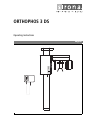
1
loqelmelp=P=ap
=
léÉê~íáåÖ=fåëíêìÅíáçåë=====
båÖäáëÜ
Sirona Dental Systems GmbH
Dear Customer
Thank you for purchasing your new ORTHOPHOS 3 DS
X-ray unit for panorama planigraphy.
For this unit we have provided you with a set of technical literature: Operating Instructions, Installation
Instructions, Installation Report / Warranty Passport,
Wiring References, Pre-Installation, Dimensions, Technical Data. Keep this literature for quick and easy reference.
In order to protect your warranty rights, please fill out the
“Installation Report / Warranty Passport” provided
together with the technician immediately after installation of the unit.
Read the Operating Instructions to familiarize yourself
with the unit before taking radiographs on the patient.
Please observe the Radiation Protection Regulations
and Warning and Safety Notes.
These Operating Instructions assume a thorough familiarity with the SIDEXIS software.
Your
ORTHOPHOS Team
Maintenance
To ensure the safety of the patient, the operators and
third parties, equipment inspections and maintenance
work must be carried out at specified intervals in order to
guarantee the operational safety and functional reliability
of your product.
It is the responsibility of the operator to ensure that the
inspections and maintenance work are carried out.
In the event that the operator fails to fulfil the obligation
to carry out inspections and maintenance work or
ignores error messages, Sirona Dental Systems GmbH
or their contracted dealer cannot assume liability for any
damage attributable to this.
2
60 86 867 D 3285
D 3285.201.06.05.02
Sirona Dental Systems GmbH
List of Contents
1
Warning and Safety Notes ........................................................................................................ 5
2
Technical Description ............................................................................................................... 8
2.1
Operating Controls and Displays........................................................................................... 12
3.1
3.2
4
Accessories ............................................................................................................................. 14
4.1
4.2
4.3
5
P1 Program..................................................................................................... 15
P11 Program................................................................................................... 15
P6.1 / P6.2 Program ....................................................................................... 16
Operation.................................................................................................................................. 17
6.1
6.2
6.3
6.4
7
Rests and supports......................................................................................... 14
Hygienic Protective Covers............................................................................. 14
Service Tool.................................................................................................... 14
Exposure Programs ................................................................................................................ 15
5.1
5.2
5.3
6
Unit ................................................................................................................. 12
Multitimer ........................................................................................................ 13
Preparing the Exposure ..................................................................................
Positioning the Patient ....................................................................................
Selecting Data at the Multitimer......................................................................
Releasing the Exposure..................................................................................
17
20
25
26
Programming ........................................................................................................................... 29
7.1
7.2
Programming Procedure................................................................................. 29
Adjustment of the Exposure............................................................................ 29
8
List of Help Messages H3/H4.................................................................................................. 30
9
Program Values ....................................................................................................................... 31
9.1
9.2
9.3
Program Values world-wide (except USA and Asia) ...................................... 31
Program Values USA...................................................................................... 32
Program Values Asia ...................................................................................... 33
10 Care the surfaces .................................................................................................................... 34
11 Error Messages........................................................................................................................ 35
12 Inspection and maintenance .................................................................................................. 36
60 86 867 D 3285
D 3285.201.06.05.02
3
båÖäáëÜ
3
Technical Data.................................................................................................. 8
Sirona Dental Systems GmbH
4
60 86 867 D 3285
D 3285.201.06.05.02
Sirona Dental Systems GmbH
1
1 Warning and Safety Notes
Warning and Safety Notes
Labeling of warning and safety information
In order to prevent injury to persons and damage to the
equipment you must also read the warning and safety
notes given in these Operating Instructions. These are
emphasized with ATTENTION and CAUTION.
Intended use
This unit has been designed for use in creating panorama radiographic exposures.
General safety information
As manufacturers of electro-medical products, we can
assume responsibility for safety-related performance of
the equipment only if maintenance, repair and modifications are carried out only by us or agencies we have
authorized for this purpose, and if components affecting
safe operation of the unit that may be needed are
replaced with original parts.
We suggest that you request a certificate showing the
nature and extent of the work performed, from those who
carry out such work, and specify that the certificate show
any changes in rated parameters or working ranges, as
well as the date, the name of the firm, and a signature.
For reasons of product safety, only original Sirona
accessories approved for this product, or accessories
from third parties which have been released by Sirona
may be used. It is the user's risk when using nonreleased accessories.
Exposures of patients may only be taken if the unit functions fault-free.
Never leave the patient unattended in the unit.
Instructions for avoiding, recognizing and correcting
unintended electromagnetic effects:
The ORTHOPHOS 3 DS X-ray System is a unit of class
A (classification according to CISPR 11, EN 60601-1-2:
1993 based off IEC 60601-1-2). This unit may be operated in a residential area, provided it is used under the
responsibility of a trained medical operator.
Safety measures during switch-on
Following extreme temperature fluctuations, condensate
formation may occur; therefore please do not switch on
the device until normal room temperature has been
reached (see chapter "Technical Description").
When switching on the unit, there must not be a patient
positioned in the unit.
If a fault occurs which requires switching the unit off and
then back on again, the patient must be taken out of the
unit at the latest before switching it on again!
60 86 867 D 3285
D 3285.201.06.05.02
5
båÖäáëÜ
This unit must not be used in areas where there is a risk
of explosion.
1 Warning and Safety Notes
Sirona Dental Systems GmbH
Interference with electromedical devices by radio
telephones
To guarantee the operational safety of electromedical
devices, it is recommended that the operation of mobile
radio telephones in the medical practice or hospital is
prohibited.
Malfunction of electronic units/devices which are
worn on the patient's body.
In order to prevent failure of electronic units and data
storage devices, e.g. radio-controlled watch and telephone card, etc., it is essential that these be removed
prior to X-ray exposure.
Radiation Protection
Observe the applicable health physics regulations.The
radiation protection facilities should be used.
The operator should remain as far away from the X-ray
tube as the cable of the release button permits.
With the exception of the patient, no other persons
may remain in the room while the exposure is being
made.
Under exceptional circumstances a third person, however not belonging to the dental practice, may then
assist. Maintain visual contact with the patient and the
unit during the exposure.
In case of faulty operation, discontinue the exposure by
releasing the exposure button.
Disassembly and reinstallation
For disassembly and reinstallation of the unit proceed as
described in the installation instructions for new installation to ensure perfect function of the unit and its stability.
Disposal
It generally applies that any disposal of this product must
comply with the relevant national regulations. Please
observe the regulations applicable in your country.
Within the European Economic Community, Council
Directive 2002/96/EU (WEEE) requires environmentally
sound recycling/disposal of electrical and electronic
devices.
Your product is marked with the adjacent symbol. Disposal of your product with domestic
refuse is not compatible with the objectives of environmentally sound recycling/disposal.
The black bar underneath the "garbage can" symbol
means that it was put into circulation after Aug. 13, 2005.
(see EN 50419:2005)
Please note that this product is subject to Council Directive 2002/96/EU (WEEE) and the applicable national law
of your country and must be recycled or disposed of in
an environmentally sound manner.
The X-ray tube assembly of this product contains a
tube with a potential implosion hazard, a small amount
of beryllium, a lead lining and mineral oil.
Please contact your dealer if final disposal of your product is required.
6
60 86 867 D 3285
D 3285.201.06.05.02
Sirona Dental Systems GmbH
Laser light localizers used
1 Warning and Safety Notes
This product incorporates a laser of class 1.
The light localizers serve for the correct positioning of
the patient.
They must not be used for other purposes. A minimum
distance of 100mm must be maintained between the eye
and the laser. Do not look into the beam. Safety operation is described in Section 6.2.
båÖäáëÜ
The light localizers may be switched on only if they function fault-free. Repair work may be carried out only by
authorized personnel.
60 86 867 D 3285
D 3285.201.06.05.02
7
2 Technical Description
2.1 Technical Data
2
Sirona Dental Systems GmbH
Technical Description
2.1 Technical Data
Nominal line voltage:
208V / 230V - 240V~
Permissible line voltage fluctuation:
±10%
Nominal current:
9.7A
Nominal frequency:
50/60Hz
Power line resistance:
max. 0.8 Ohm
Fuse at the distribution panel:
20A slow blow
Rating:
2.1kW
Tube voltage:
60 – 80 kV
Tube current:
6 – 11mA
Curve form of high voltage:
high frequency
multipulse Residual ripple ≤ 4kV
Rotation time:
see page 31
Exposure time:
see page 31
Reproduction scale:
With P1 program, medium mandibular arch (plane center) ca.
1:1,19. The image at the image receiver is approximately 19%
larger than the real proportions.
Focus size, according to IEC 336,
measured in central ray:
0,5mm
Focus marking:
Automatic exposure blockage (see page 27):
The duration of the exposure blockage (cool-off period) depends on
the kV/mA step set and the actually triggered radiation time.
Depending on the tube load, pause times up to 200s are set automatically.
Example: For P1 program with exposure data 74kV/10mA and a
radiation time of 11.3s a pause of 200s results.
8
Equipment of protective class I
Protection against electric shock:
Type B equipment
Protection against penetration of water:
Ordinary equipment (without protection)
Mode of operation:
Continuous operation
Long time power rating:
64W
Target material:
Tungsten
Loading factors concerning leakage radiation:
1.1mA / 80 kV
Leakage radiation:
≤ 1mGy/h
60 86 867 D 3285
D 3285.201.06.05.02
Sirona Dental Systems GmbH
2 Technical Description
2.1 Technical Data
Source - Image receptor distance:
497mm
Transport and storing temperature:
-40°C – +70°C (-40°F – 158°F)
Relative humidity:
10% – 95%
Permissible operating temperature:
According to IEC 601-1 between +10°C and +40°C (50°F – 104°F)
Type:
Digital CCD-technology line sensor,
can be plugged to Panorama position.
External dimensions:
280mm x 120mm x 35mm
Active sensor surface:
Panorama: 138 mm x 5.9 mm
Resulting image format:
Panorama: depends on selected program,
max. 138 x 288mm
Detail recognition:
Panorama: 0.09mm pixel size
båÖäáëÜ
Sensor (image receptor):
Minimum requirements for the PC systems:
Hard disk:
> 2 GByte / database
> 50 MByte / SIDEXIS installation
RAM:
at least 64 MB
Drives:
CD-ROM
3.5" diskette (one per system / network)
MOD drive min. 640 MByte (one per system / network)
Operating system:
Windows 98
Windows NT 4.0 / Service Pack > 5
Graphics system:
Resolution at least 1024 x 768 pixels,
color depth at least 8 bit
Network:
10 / 100 MBit Ethernet
Communication connection:
RJ45 for LAN cable
Laser light localizer
Magnitude:
300mm long, 5mm wide
Max. radiant power:
350J/m2
Pulse duration:
100s
ORTHOPHOS 3 DS has been inspected by the VDE Testing and Certification Institute for compliance with EN 606011, EN 60601-2-28 and EN 60601-1-3 and has been found to comply with these regulations.
Original language: german
This product is provided with a CE marking in accordance with the regulations stated in the Directive 93/42/
EEC of June 14, 1993 concerning medical products.
0123
Reg. No.: China
SFDA (I) 20053301583
60 86 867 D 3285
D 3285.201.06.05.02
9
2 Technical Description
2.1 Technical Data
Sirona Dental Systems GmbH
Cooling curve for the tube housing:
HUx104 1HU = 1,35 Joule
130
120
110
100
90
80
70
60
50
40
30
20
10
t
0
20
40
60
80
100
120
140
480
160
180
200
220
240
min
Anode cooling caracteristic:
HUx103 1HU = 1,35 Joule
20
15
10
5
t
0
1
2
3
4
5
6 min
Heating curve for tube housing:
HUx103 1HU = 1,35 Joule
1000
t
0
1
2
3
4
5
6
h
Reference axis:
Reference axis
Anode angle
7°
10°
10
60 86 867 D 3285
D 3285.201.06.05.02
Sirona Dental Systems GmbH
2 Technical Description
2.1 Technical Data
Radiation fields of the laser light localizers:
60°
5°
60°
båÖäáëÜ
32°
60 86 867 D 3285
D 3285.201.06.05.02
11
3 Operating Controls and Displays
3.1 Unit
3
Sirona Dental Systems GmbH
Operating Controls and Displays
3.1 Unit
4
9
3
2
10
1.
Main switch
2.
Patient positioning mirror
3.
Head holder with adjusting knob for temple supports
4.
Image receiver
5.
Diaphragm
6.
Diaphragm wheel
7.
Height adjustment buttons
Additional function: key ↑ switches light localizer on
8.
Knob for image receiver removal or insertion
9.
Height adjustment
Light localizer horizontal light beam FH
1
10. Light localizer central light beam
11. Multitimer
11
12
7 8
5 6
60 86 867 D 3285
D 3285.201.06.05.02
Sirona Dental Systems GmbH
3 Operating Controls and Displays
3.2 Multitimer
3.2 Multitimer
”Unit ON” LED
Radiation present indicator
Exposure key
P I
I I.3
66
I0
Digital display for exposure program /
exposure time
with – + keys for exposure programs.
Digital display for kV/mA paired values
båÖäáëÜ
P I
66
I0
with – + keys for overriding kV values.
Patient symbol keys
with programmed kV/mA values
Memory program key
kV/mA matched values
Key with service function
Rotation test key T
without radiation
Return key R
The LED blinks when the system is not ready.
60 86 867 D 3285
D 3285.201.06.05.02
13
4 Accessories
4.1 Rests and supports
4
Sirona Dental Systems GmbH
Accessories
4.1 Rests and supports
*
B*
135°C
275°F
With* marked accessories can be sterilized.
Sterilize only in an autoclave at 135°C, 2.1bar
(275°F).
For reorders:
A* Yellow bite block
(5 pcs)
Order No. 89 21 843
B* Yellow contact segment
for patient without front teeth
(5 pcs)
Order No. 89 31 545
A*
C
C
Head positioner complete,
incl. 4x D
Order No. 18 88 770
D* Ear fixation
(10 pcs)
F
Order No. 18 88 838
Contact spacer
Order No. 33 10 336
D*
F
4.2 Hygienic Protective Covers
(disposable)
Before each exposure, the hygienic protective covers
should be attached.
For better illustration of the components, the following
figures are shown without the hygienic protective covers.
For orders:
G
G
For temple supports and handles
(500 pcs)
Order No. 33 14 098
Dimensions: 210 (140)mm x 57mm
H
For bite block and contact segment
(500 pcs)
Order No. 33 14 080
Dimensions: 80mm x 40mm
H
4.3 Service Tool
Needle phantom
Order No. 33 11 235
14
60 86 867 D 3285
D 3285.201.06.05.02
Sirona Dental Systems GmbH
5
5 Exposure Programs
5.1 P1 Program
Exposure Programs
5.1 P1 Program
Complete standard exposure
Yellow bite block or contact segment.
båÖäáëÜ
•
5.2 P11 Program
with constant 1.25-fold magnification
e.g. for implantology
•
60 86 867 D 3285
D 3285.201.06.05.02
Yellow bite block or contact segment.
15
5 Exposure Programs
5.3 P6.1 / P6.2 Program
Sirona Dental Systems GmbH
5.3 P6.1 / P6.2 Program
Lateral exposures of the temporoman-dibular joints
with closed and open mouth.
(4 exposures on one image)
•
P6.1
P6.2
P6.2
P6.1
P6.1 Outer Image:
Closed mouth
•
Head positioner
Insert head positioner (see page 17).
Actuate P6.1
After P6.1 is completed, the unit automatically returns to the initial position.
P6.2 Inner Image:
Open mouth
•
Have the patient open his mouth and actuate P6.2.
P6.1
P6.2
16
60 86 867 D 3285
D 3285.201.06.05.02
Sirona Dental Systems GmbH
6
6 Operation
6.1 Preparing the Exposure
Operation
6.1 Preparing the Exposure
Insert Contact Spacer F
F
Application: For all exposure programs.
Always place the contact spacer where, as a result of
anatomical features, with correct head positioning there
is no contact with the forehead (no 3-point fixing).
After positioning the head, press the contact spacer
onto the tube and push it down to the forehead contact.
båÖäáëÜ
3
Insert Head Positioner C
Z
C
A
Insert Bite Block A
B
60 86 867 D 3285
D 3285.201.06.05.02
Application: Exposure program P6.
Open temple supports with knob (3). remove rubber
inserts Z and insert head positioner up to stop.
or contact segment B.
Application: Exposure programs P1 and P11.
17
6 Operation
6.1 Preparing the Exposure
Sirona Dental Systems GmbH
Switching ON the Unit
ATTENTION
Following extreme temperature fluctuations, condensate
formation may occur; therefore please do not switch on
the device until normal room temperature has been
reached (see chapter "Technical Description").
•
Depress the main switch (1) into the ”I” position and
allow one minute warm up time.
•
The LED in the upper left corner of the Multitimer will
light up.
•
The unit adjusts itself automatically:
•
The rotating unit moves a little to the right and left.
1
ATTENTION
When switching on the unit, there must not be a patient
positioned in the unit.
If a fault occurs which requires switching the unit off and
then back on again, the patient must be taken out of the
unit at the latest before switching it on again!
Switching ON the PC
•
18
Prepare SIDEXIS program on PC for ORTHOPHOS (XP) exposure stand-by
(see SIDEXIS User’s Manual).
60 86 867 D 3285
D 3285.201.06.05.02
Sirona Dental Systems GmbH
6 Operation
6.1 Preparing the Exposure
At the Multitimer
Exposure key
the program and exposure parameters employed with
the last patient appear.
P
B
I
62
8
shows you the exposure program sequentially and
the respective maximum exposure time.
B
gives you the kV/mA matched value pair. The LED
over the respective patient symbol lights up.
C
LED over the return key R blinks.
Move the rotating unit into place for patient positioning
by tapping one of the return keys R.
i
NOTE
You can release a test rotation without radiation via
the exposure button after having pressed the T button.
The LED over the R key at the Multitimer switches off to
let you know that the unit is ready for the exposure.
C
Help Message
Should the LED over the R key go on blinking, call up the
help message H3/H4 to look for the reason.
List of Help Messages see page 30.
Image receiver
•
8
The image receiver 7 must be pushed all the way to
the stop (turn the rotary knob 8 to the left).
i
NOTE
To remove the image receiver, turn the rotary knob 8 to
the right and pull the image receiver out.
7
ATTENTION
Do not drop it!
60 86 867 D 3285
D 3285.201.06.05.02
19
båÖäáëÜ
A
A
6 Operation
6.2 Positioning the Patient
Sirona Dental Systems GmbH
6.2 Positioning the Patient
•
Have the patient remove all metallic objects, such
as glasses and jewelry, from the head and neck regions. Have him take out removable dentures.
•
Physical constitution, clothing, bandages etc. must
not interfere with the functioning of the unit! Perform
a test run with the T button, (see page 19)
•
Insert bite block / contact segment or head positioner, see page 17
For selection see chapter ”Exposure Programs”.
Standard Exposure Program P1 and P11…
•
Have the patient stand in front of the mirror.
Pressing the height adjustment key ↑ automatically
switches on the light localizer for 1minute.
i
NOTE
Please make sure that the light beam strikes the eyes of
the patient only very briefly.
20
60 86 867 D 3285
D 3285.201.06.05.02
Sirona Dental Systems GmbH
6 Operation
6.2 Positioning the Patient
•
Using the ↑ and ↓ buttons, adjust unit height so that
the bite block and the anterior teeth match up.
•
Have the patient grip the handles.
•
Have the patient bite the bite block at the indentation.
The upper anterior teeth should be directly in the indentation, and the lower anterior teeth should be
moved forward up to the stop.
… with Contact Segment
For patients without anterior teeth.
•
Adjust the unit height so that contact segment and
subnasals match up.
•
The contact segment should be just under the patient's nose.
•
Ensure that the upper and lower jaws are lined
up with each other.
This is facilitated by a cotton roll.
i
NOTE
The height adjustment motor starts up slowly and then
picks up speed. Motoric movement is accompanied by
an acoustic signal.
60 86 867 D 3285
D 3285.201.06.05.02
21
båÖäáëÜ
… with Bite Block
6 Operation
6.2 Positioning the Patient
Sirona Dental Systems GmbH
•
Make certain the spine is tilted slightly as shown.
This moves the patient's cervical vertebrae into a more
stretched out position.
The cervical vertebrae ”stretched out” ensures that the
area of the anterior teeth is not over exposed.
In special cases, it is also possible to position for sitting
patients.
CORRECT
INCORRECT
22
60 86 867 D 3285
D 3285.201.06.05.02
Sirona Dental Systems GmbH
6 Operation
6.2 Positioning the Patient
•
Swing out the mirror by pressing on A.
•
Position the patient's head so that the bite plane is
tilted slightly forward.
•
Switch the light localizer on by pressing briefly on
the height adjustment key ↑ .
The light localizer serve for the correct positioning of
the patient.
9
i
NOTE
Please make sure that the light beam strikes the eyes of
the patient only very briefly.
i
A
NOTE
The horizontal light beam FH
should go through the lower margins of the orbits and the
upper margin of the external auditory orifices (Frankfurt
Horizontal).
FH
•
For this reason the FH localizer (9) can be adjusted
manually upwards and downwards.
•
Finely adjust the head inclination for the FH line adjustment by tapping the buttons ↑ or ↓ for vertical
unit movement.
The central light beam
•
should be directed onto the center of the anterior
teeth or the middle of the face.
•
Align the center of the anterior teeth or the middle of
the face to the central light line.
•
Close the temple supports with knob (3).
•
Insert contact spacer F (see page 17) and slide
down until it makes contact with the front.
•
Swing back the mirror.
•
Have the patient take a small step toward the column.
•
Recheck the FH position.
F
3
60 86 867 D 3285
D 3285.201.06.05.02
23
båÖäáëÜ
The light localizer switches off automatically after about 1
minute.
6 Operation
6.2 Positioning the Patient
Sirona Dental Systems GmbH
Exposure of the Temporo-mandibular Joint.
P6 Program with Head Positioner
•
For these exposures insert the head positioner (see
page 17).
•
Remove bite block.
•
Using the ↑ and ↓ buttos, adjust unit height so that
ear fixations and external auditory canals match up.
•
Position the patient's head in the head positioner.
Close the temple supports so that the ear fixations
are inserted in the external auditory canals.
•
Swing out the mirror.
•
To set the correct position, switch on the light localizer by pressing the height adjsutment key ↑ .
The horizontal light beam FH should go through
the lower margins of the orbits and the upper margins of the external auditory orifices (Frankfurt Horizontal plane FH).
For this reason the FH localizer (9) can be adjusted manually upwards and downwards.
•
Ensure that the spine is slightly tilted as described
before.
(Have the patient take a small step toward the column).
•
Close temple supports (3) with knob.
•
Insert contact spacer F (see page 17) and slide
down until it makes contact with the front.
•
Swing back the mirror.
F
3
24
60 86 867 D 3285
D 3285.201.06.05.02
Sirona Dental Systems GmbH
6 Operation
6.3 Selecting Data at the Multitimer
6.3 Selecting Data at the Multitimer
Select the Exposure Program
•
c
s
P I
66
I0
The exposure program selected, e.g. P1, and the corresponding maximum exposure time are alternatively
shown on the digital display.
c
s
Manuall
i
NOTE
When, with preselection of the exposure program, “O 1”
appears on the display instead of, for example, “P 1”, you
have erroneously selected a mode provided for servicing. You can leave this mode by pressing the ”Memory”
button and then ”Program +” or by switching to another
exposure program.
båÖäáëÜ
I I.3
Select the Exposure Program by pressing the – +
keys.
Select Exposure Data
by tapping one of the four patient symbol keys.
The LED above the key will then light up, and the respective kV/mA matched pair will appear on the digital display.
Manually, the exposure data can be modified with the
– + keys.
The LED over the patient symbol key is then no
longer illuminated.
The mA value is the same for all kV values. (See chapter
”Program Values”).
The kV/mA matched values for the patient symbol keys
are factory programmed. Should you need to modify
these values, see the chapter entitled ”Programming”.
60 86 867 D 3285
D 3285.201.06.05.02
25
6 Operation
6.4 Releasing the Exposure
Sirona Dental Systems GmbH
6.4 Releasing the Exposure
ATTENTION
Operator: Observe the radiation protection guidelines
explained, see page 6.
Before releasing the exposure always check display for
proper exposure data for the patient beeing radiographed.
•
The exposure is released by keeping the exposure key pressed.
The rotation movement runs automatically in accordance with the exposure program selected.
P I
74
I0
c
s
For P6 program only
The rotation unit returns back into the start position after
having completed the program part P6.1. Then have the
patient open his mouth wide and release the second program part P6.2 .
During radiation
the X-ray radiation indicator lights up. The radiation
duration is additionally accompanied by an acoustic
signal.
•
The exposure ends when the LED over the R key
flashes. Rotation and radiation automatically
switch off.
Open the temple supports and have the patient step out
Interrupting the Exposure
Automatic Exposure Blockage and Error Message
see next page.
The program number (e. g. P1) is indicated at the Multitimer.
After the end of the exposure
the exposure time actually required for the exposure
lights up and the exposure is displayed on the PC.
i
NOTE
In case of disturbances of the data transmission to the
PC, the unit changes automatically into a safe mode,
which saves the acquired image until the image has
been transmitted by a service program (SiRescue). The
safe mode is indicated by the help message H4 20.
ATTENTION
In this condition the unit or the PC may not be switched
off, in order to prevent the saved image from being deleted.
For operating the SiRescue service program please
observe the corresponding software description in the
SIDEXIS User Manual.
26
60 86 867 D 3285
D 3285.201.06.05.02
Sirona Dental Systems GmbH
6 Operation
6.4 Releasing the Exposure
The help message H4 20 is no longer displayed after the
image has been transmitted by the SiRescue service
program.
i
NOTE
Only then may the units be switched off or put into the
ready for exposure state.
After the exposure
Acknowledge awareness of the exposure time actually
required for the exposure by pressing the return key R.
Then bring the rotary unit in to the starting position by
pressing the return key R once again.
Interrupting the Exposure
If the exposure key is prematurely released, the exposure is interrupted and terminated.
9.8
74
I0
The kV/mA value and the LED over key R blink at the
Multitimer.
The exposure time passed until the interruption is
shown.
Press the R key on the Multitimer twice.
Check patient positioning and repeat the exposure.
Automatic Exposure Blockage
(Protection of X-ray tube)
I09
The automatic exposure blockage prevents premature
triggering of a new exposure.
After the exposure key has been actuated, the automatic
cool-off pause is indicated.
The LED over key R continues flashing until the cool-off
time has elapsed.
The exposure cannot be triggered until the LED over key
R has gone out.
Example see page 8
60 86 867 D 3285
D 3285.201.06.05.02
27
båÖäáëÜ
After return travel to the start position the unit is
automatically ready for another exposure.
See chapter 'Positioning the Patient'.
6 Operation
6.4 Releasing the Exposure
Sirona Dental Systems GmbH
Error Message E ...
E2
0I
Messages such as E2/01 in the kV/mA field indicate
errors.
The LED over the R key blinks.
All unit functions are blocked.
•
Press the key R on the Multitimer to reset display
(poss. more than once).
•
If the error message E continues to light up, switch
the unit off and back on, if for an exposure the X-ray
image is displayed on the PC.
ATTENTION
The turn-off time must be at least 60s; otherwise the unit
will not function correctly.
If error message has disappeared, all unit functions are
normal again.
For List of Error Messages with remedy discription see
page 35.
28
60 86 867 D 3285
D 3285.201.06.05.02
Sirona Dental Systems GmbH
7
7 Programming
7.1 Programming Procedure
Programming
7.1 Programming Procedure
I
In the factory kV/mA values have been assigned to the
four program buttons.
For free programming the buttons can be programmed
with different values.
See chapter 'Program Values'.
1.
1.
Push buttons – + to select program number P1 ... to
be changed.
2.
Push – + buttons to set desired kV value on the digital display.
3.
Push memory button. The LED over the memory
button blinks.
4.
Push the patient symbol button to be reprogrammed. The LED above this button lights up.
2.
4.
3.
båÖäáëÜ
P I
66
I0
The LED above the memory button is switched off.
The new values are now stored.
Programming is complete.
Please enter the new value in the 'Freely programmed
values' table.
7.2 Adjustment of the Exposure
The adjustment of the exposure is set to 03 at the factory.
If the degree of exposure is to be changed, use the supplied screwdriver as shown in the illustration.
During adjustment the corresponding switch position is
briefly displayed
(example 04).
Step switch set to– = lower dose,
noisy exposures
Step switch set to+ =higher dose,
low-noise exposures
04
i
NOTE
Changing the adjustment of the exposure automatically
alters the programmed kV/mA values.
Chapter 'Program Values'., see page 31.
+
–
60 86 867 D 3285
D 3285.201.06.05.02
29
8 List of Help Messages H3/H4
8
Sirona Dental Systems GmbH
List of Help Messages H3/H4
You want to release an exposure but the Ready-LED on
Multitimer above the R key is still blinking:
ATTENTION
In case of unit failure the test key T on the Multitimer must
be pressed first (radiation protection measure!).
H3
0I
•
Press the X-ray exposure key on Multitimer. H3/H4
help message appears on the kV/mA display.
•
Read on the following list what is to be done to get
the unit ready for the exposure.
•
Before carrying out the corresponding indication,
press return key R on the Multitimer to acknowledge
the help message.
Help Message H3
H3 01 Press one of the R buttons to return the rotation
unit to the start position.
H3 20Press R key on Multitimer to confirm exposure
data.
Help Message H4
H4 01Slide in the image receiver up to stop.
H4 03Set SIDEXIS operational on the PC.
H4 10Image receptor not suitable for the set exposure.
H4 20Transfer exposure by SiRescue service program
to the PC, see SIDEXIS User Manual.
CAUTION Do not switch off the unit until the help message goes out.
30
60 86 867 D 3285
D 3285.201.06.05.02
Sirona Dental Systems GmbH
9
9 Program Values
9.1 Program Values world-wide (except USA and Asia)
Program Values
9.1 Program Values world-wide (except USA and Asia)
Kennziffer 30
Program
duration
approx.
Exposure
time
Factory-programmed values
with an adjustment of the
exposure of 03
P1
21s
11.3s
66/10
70/10
74/10
78/10
P6.1 + P6.2
21s + 21s
7.8s
68/10
72/10
76/10
80/10
P11
18s
11,3s
66/10
70/10
74/10
78/10
Freely programmed values or
values with other adjustment of
the exposure: ....
– please enter here –
båÖäáëÜ
Program
These values serve only as user reference times.
Possible kV/mA combinations – can be selected manually
60
62
64
66
68
70
72
74
76
78
80
kV
10
10
10
10
10
10
10
10
10
10
10
mA
60 86 867 D 3285
D 3285.201.06.05.02
31
9 Program Values
9.2 Program Values USA
Sirona Dental Systems GmbH
9.2 Program Values USA
Index 2A
Program
Program
duration
approx.
Factory-programmed values
with an adjustment of the
exposure of 03
Exposure
time
P1
21s
11.3s
66/10
70/10
74/10
78/10
P6.1 + P6.2
21s + 21s
7.8s
68/10
72/10
76/10
80/10
P11
18s
11,3s
66/10
70/10
74/10
78/10
Freely programmed values or
values with other adjustment of
the exposure: ....
– please enter here –
These values serve only as user reference times.
By actuating one of the two smaller or one of the two larger patient symbols, you can change between the two kv/mA pair
groups. By actuating the kV/mA + - keys, you can select the individual values of the kV/mA groups.
Possible kV/mA value pairs – manually selectable with the two smaller patient symbols
60
60
60
62
64
66
68
70
72
74
76
kV
6
7
10
10
10
10
10
10
10
10
10
mA
Possible kV/mA value pairs – manually selectable with the two larger patient symbols
60
62
64
66
68
70
72
74
76
78
80
kV
10
10
10
10
10
10
10
10
10
10
10
mA
32
60 86 867 D 3285
D 3285.201.06.05.02
Sirona Dental Systems GmbH
9 Program Values
9.3 Program Values Asia
9.3 Program Values Asia
Index 1A
Program
duration
approx.
Factory-programmed values
with an adjustment of the
exposure of 03
Exposure
time
P1
21s
11.3s
68/10
72/10
76/11
78/11
P6.1 + P6.2
21s + 21s
7.8s
70/10
74/10
78/11
80/11
P11
18s
11,3s
68/10
72/10
76/11
78/11
Freely programmed values or
values with other adjustment of
the exposure: ....
– please enter here –
båÖäáëÜ
Program
These values serve only as user reference times.
By actuating one of the two smaller or one of the two larger patient symbols, you can change between the two kv/mA pair
groups. By actuating the kV/mA + - keys, you can select the individual values of the kV/mA groups.
Possible kV/mA value pairs – manually selectable with the two smaller patient symbols
60
62
64
66
68
70
72
74
76
78
80
kV
10
10
10
10
10
10
10
10
10
10
10
mA
Possible kV/mA value pairs – manually selectable with the two larger patient symbols
60
62
64
66
68
70
72
74
76
78
80
kV
11
11
11
11
11
11
11
11
11
11
11
mA
60 86 867 D 3285
D 3285.201.06.05.02
33
10 Care the surfaces
10
Sirona Dental Systems GmbH
Care the surfaces
Cleaning
Remove dirt and disinfectant residues regularly with a
normal commercial cleaning medium.
Do not allow any liquid to enter the ventilating slots!
To avoid permanent staining, quickly clean away any
medicament that spills on the surface.
Do not clean the lens of the laser with alcohol.
Disinfecting
Disinfecting is possible by wiping with surface disinfectant. Observe the directions of the manufacturer when
using! Use only tested and approved media!
Do not use agents containing the components phenol,
peracetic acid, peroxide and other agents splitting up
oxygen, sodium hypochlroite and agents splitting off
iodine.
34
60 86 867 D 3285
D 3285.201.06.05.02
Sirona Dental Systems GmbH
Error Messages
E... error messages
Remedy
E1 01
One of the keys on the Multitimer was pressed
during start-up of the unit.
Press R key on Multitimer to reset display.
E1 03
Faulty communication with the unit.
Press R key on Multitimer to reset display.
E2 01
Appears after pressing exposure key.
X-ray head overheated.
Cool-down periods ignored.
Press R key on Multitimer to reset display.
E2 03
Faulty communication with the Multitimer.
Press R key on Multitimer to reset display.
E2 04
Zero-Power was re-initialized.
Press R key on Multitimer to reset display. Freely programmed values (see page 31) are canceled, sorry. Please
reprogram (see page 29).
E2 10
Max. radiation time of program exceeded
Press R key on Multitimer to reset display.
E2 20
Appears after pressing the exposure key,
Close x-ray room door.
Press R key on Multitimer to reset display.
If error re-appears, poss. break in cable.
e.g. if x-ray room door contact not closed.
Exposure lead in Multitimer cable damaged.
E2 35
Invalid data in data memory.
Press R key on Multitimer to reset display.
E3 09
Movement of height adjustment obstructed.
Check that height adjustment can move freely.
Press R key on Multitimer to reset display.
båÖäáëÜ
11
11 Error Messages
WARNING!
If this fault message occurs repeatedly during the motordriven up and down movement of the rotary unit, especially
when no patient is positioned, switch off the unit immediately
and inform your service engineer without delay.
E4 01
Exposure interrupted by SIDEXIS.
Press R key on Multitimer to reset display.
Check PC for readiness.
For error messages which are not contained in this list, switch the unit off and back on if for an exposure the X-ray image is
displayed on the PC.
ATTENTION
If an error is displayed again after switching the unit off
and then on again, please contact your service technician.
ATTENTION
The turn-off time must be at least 60s; otherwise the unit
will not function correctly.
60 86 867 D 3285
D 3285.201.06.05.02
35
12 Inspection and maintenance
12
Sirona Dental Systems GmbH
Inspection and maintenance
Inspection and maintenance work must be performed at
regular intervals to protect the safety and health of
patients, users and third parties.
Annual inspection performed by the operator or
other authorized personnel
As the operator, you should ensure the safety and reliability of your system by performing maintenance on it at
regular intervals (at least once annually) or having this
work performed by your dental dealership.
Maintenance performed by the service
technician
In addition to the scheduled annual inspection by the
user or persons contracted to perform this, a maintenance inspection must be performed after 4, 7 10 and
then every two years.
Checking image quality
At regular intervals, however at least once a year, the
user must evaluate the image quality.
For digital image receptors, the increasing number of
repeated image processing operations to be made with
the brightness or contrast control in the image processing software (e.g. SIDEXIS) is used as evaluation criterion.
If this evaluation criterion is considered to be satisfied
irrespective of the patient’s anatomy or possible error
sources such as patient positioning, a technician should
be consulted immediately for elimination of possible system defects.
In addition it is necessary to observe country-specific
requirements.
Furthermore, we would like to call your attention to our
Quality Image Service. For this, please contact your
dental dealer or the manufacturer directly.
36
60 86 867 D 3285
D 3285.201.06.05.02
tÉ=êÉëÉêîÉ=íÜÉ=êáÖÜí=íç=ã~âÉ=~åó=~äíÉê~íáçåë=ïÜáÅÜ=ã~ó=ÄÉ=ÇìÉ=íç=íÉÅÜåáÅ~ä=áãéêçîÉãÉåíëK
«=páêçå~=aÉåí~ä=póëíÉãë=dãÄe=OMMN
a=POURKOMNKMSKMRKMO===MPKOMMT
péê~ÅÜÉW=ÉåÖäáëÅÜ=
ûKJkêKW= NMU=ROP
páêçå~=aÉåí~ä=póëíÉãë=dãÄe
áå=íÜÉ=rp^W
áå=`~å~Ç~W
c~Äêáâëíê~≈É=PN
SQSOR=_ÉåëÜÉáã
dÉêã~åó
ïïïKëáêçå~KÅçã
páêçå~=aÉåí~ä=póëíÉãë=ii`
QUPR=páêçå~=aêáîÉI=pìáíÉ=NMM
`Ü~êäçííÉI=k`=OUOTP
rp^
páêçå~=`~å~Ç~
PORM=oáÇÖÉï~ó=aêáîÉ=J=råáí=R
jáëëáëë~ìÖ~I=låí~êáç=iRi=RvS
`~å~Ç~
mêáåíÉÇ=áå=dÉêã~åó
fãéêáã¨=Éå=^ääÉã~ÖåÉ
lêÇÉê=kç
SM=US=UST=a=POUR