1
Allen-Bradley
9/Series CNC
AMP
Reference
Manual
Important User Information
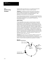
Because of the variety of uses for the products described in this
publication, those responsible for the application and use of this control
equipment must satisfy themselves that all necessary steps have been taken
to assure that each application and use meets all performance and safety
requirements, including any applicable laws, regulations, codes and
standards.
The illustrations, charts, sample programs and layout examples shown in
this guide are intended solely for purposes of example. Since there are
many variables and requirements associated with any particular
installation, Allen-Bradley does not assume responsibility or liability
(to include intellectual property liability) for actual use based upon the
examples shown in this publication.
Allen-Bradley publication SGI-1.1, Safety Guidelines for the Application,
Installation, and Maintenance of Solid State Control (available from your
local Allen-Bradley office), describes some important differences between
solid-state equipment and electromechanical devices that should be taken
into consideration when applying products such as those described in this
publication.
Reproduction of the contents of this copyrighted publication, in whole or
in part, without written permission of Allen-Bradley Company, Inc., is
prohibited.
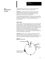
Throughout this manual we use notes to make you aware of safety
considerations:
ATTENTION: Identifies information about practices or
circumstances that can lead to personal injury or death, property
damage or economic loss.
Attention statements help you to:
identify a hazard
avoid the hazard
recognize the consequences
Important: Identifies information that is critical for successful application
and understanding of the product.
Summary of Changes
9/Series AMP Reference Manual
October 2000
Summary of Changes
Summary of Changes
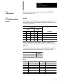
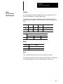
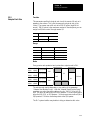
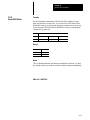
The following is a list of the larger changes made to this manual since its
last printing. Other, less significant changes, were also made throughout.
Homing sequence
Homing sequence using distance--coded markers (DCMs)
Shunt resistor configuration
Reserved custom parameters
Integrating a linear feedback device
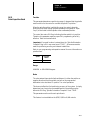
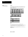
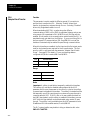
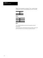
Revision Bars
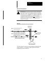
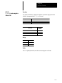
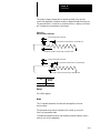
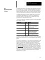
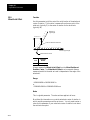
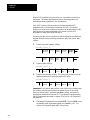
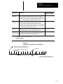
We use revision bars to call your attention to new or revised information.
A revision bar appears as a thick black line on the outside edge of the page,
as indicated here.
Preface
P-2
Table of Contents
9/Series CNC AMP Reference Manual
Chapter 1
Using This Manual
1.0
1.1
1.2
1.3
1.4
Manual Objective . . . . . . . . . . . . . . . . . . . . . . . . . . . . . . . . . . . . . . . . . . . . . . . . . . . . . . . . . . . . . . . . . . . .
An Overview of AMP . . . . . . . . . . . . . . . . . . . . . . . . . . . . . . . . . . . . . . . . . . . . . . . . . . . . . . . . . . . . . . . . . .
Terms and Conventions . . . . . . . . . . . . . . . . . . . . . . . . . . . . . . . . . . . . . . . . . . . . . . . . . . . . . . . . . . . . . . . .
Attentions and Important Information . . . . . . . . . . . . . . . . . . . . . . . . . . . . . . . . . . . . . . . . . . . . . . . . . . . . . .
Related Publications . . . . . . . . . . . . . . . . . . . . . . . . . . . . . . . . . . . . . . . . . . . . . . . . . . . . . . . . . . . . . . . . . .
Chapter 2
Using AMP Applications and ODS Utilities
2.0
2.1
2.2
2.3
Chapter Overview . . . . . . . . . . . . . . . . . . . . . . . . . . . . . . . . . . . . . . . . . . . . . . . . . . . . . . . . . . . . . . . . . . . .
Selecting the AMP Application . . . . . . . . . . . . . . . . . . . . . . . . . . . . . . . . . . . . . . . . . . . . . . . . . . . . . . . . . . .
AMP Editor Utility . . . . . . . . . . . . . . . . . . . . . . . . . . . . . . . . . . . . . . . . . . . . . . . . . . . . . . . . . . . . . . . . . . .
Selecting AMP Files . . . . . . . . . . . . . . . . . . . . . . . . . . . . . . . . . . . . . . . . . . . . . . . . . . . . . . . . . . . . . . . . . .
2.3.1 Creating a New AMP File . . . . . . . . . . . . . . . . . . . . . . . . . . . . . . . . . . . . . . . . . . . . . . . . . . . . . . . . .
2.3.2 Opening an Existing AMP File . . . . . . . . . . . . . . . . . . . . . . . . . . . . . . . . . . . . . . . . . . . . . . . . . . . . . .
2.3.3 Copying an AMP File from the Current Project . . . . . . . . . . . . . . . . . . . . . . . . . . . . . . . . . . . . . . . . . .
2.3.4 Renaming an AMP File . . . . . . . . . . . . . . . . . . . . . . . . . . . . . . . . . . . . . . . . . . . . . . . . . . . . . . . . . . .
2.4 Deleting an AMP File . . . . . . . . . . . . . . . . . . . . . . . . . . . . . . . . . . . . . . . . . . . . . . . . . . . . . . . . . . . . . . . . .
2.5 Copying an AMP File from Another Project . . . . . . . . . . . . . . . . . . . . . . . . . . . . . . . . . . . . . . . . . . . . . . . . . .
2.6 Selecting a Parameter Group . . . . . . . . . . . . . . . . . . . . . . . . . . . . . . . . . . . . . . . . . . . . . . . . . . . . . . . . . . . .
2.7 Setting Parameter Values . . . . . . . . . . . . . . . . . . . . . . . . . . . . . . . . . . . . . . . . . . . . . . . . . . . . . . . . . . . . . .
2.8 Quick Edit . . . . . . . . . . . . . . . . . . . . . . . . . . . . . . . . . . . . . . . . . . . . . . . . . . . . . . . . . . . . . . . . . . . . . . . . .
2.9 Saving AMP Files . . . . . . . . . . . . . . . . . . . . . . . . . . . . . . . . . . . . . . . . . . . . . . . . . . . . . . . . . . . . . . . . . . . .
2.9.1 Save Option . . . . . . . . . . . . . . . . . . . . . . . . . . . . . . . . . . . . . . . . . . . . . . . . . . . . . . . . . . . . . . . . . . .
2.9.2 Save As Option . . . . . . . . . . . . . . . . . . . . . . . . . . . . . . . . . . . . . . . . . . . . . . . . . . . . . . . . . . . . . . . .
2.10 Recover Backup File . . . . . . . . . . . . . . . . . . . . . . . . . . . . . . . . . . . . . . . . . . . . . . . . . . . . . . . . . . . . . . . . .
2.11 Exiting the AMP Editor . . . . . . . . . . . . . . . . . . . . . . . . . . . . . . . . . . . . . . . . . . . . . . . . . . . . . . . . . . . . . . .
2.12 Downloading AMP Files . . . . . . . . . . . . . . . . . . . . . . . . . . . . . . . . . . . . . . . . . . . . . . . . . . . . . . . . . . . . . .
2.12.1 Downloading an AMP File from the Workstation to the Control . . . . . . . . . . . . . . . . . . . . . . . . . . . . . .
2.12.2 Downloading an AMP File to a Storage Device, then to the Control . . . . . . . . . . . . . . . . . . . . . . . . . . .
2.13 Uploading AMP Files . . . . . . . . . . . . . . . . . . . . . . . . . . . . . . . . . . . . . . . . . . . . . . . . . . . . . . . . . . . . . . . .
2.13.1 Uploading an AMP File from the Control to the Workstation . . . . . . . . . . . . . . . . . . . . . . . . . . . . . . . .
2.13.2 Uploading an AMP File from a Control to a Storage Device, and then to a Workstation . . . . . . . . . . . . .
2.14 Enabling DH+ Pass Through . . . . . . . . . . . . . . . . . . . . . . . . . . . . . . . . . . . . . . . . . . . . . . . . . . . . . . . . . . .
2.15 Documenting AMP Files . . . . . . . . . . . . . . . . . . . . . . . . . . . . . . . . . . . . . . . . . . . . . . . . . . . . . . . . . . . . . .
2.15.1 Creating a Document File . . . . . . . . . . . . . . . . . . . . . . . . . . . . . . . . . . . . . . . . . . . . . . . . . . . . . . . .
2.15.2 Printing or Displaying an AMP Document File . . . . . . . . . . . . . . . . . . . . . . . . . . . . . . . . . . . . . . . . . .
Chapter 3
Configuring Axes
3.0 Chapter Overview . . . . . . . . . . . . . . . . . . . . . . . . . . . . . . . . . . . . . . . . . . . . . . . . . . . . . . . . . . . . . . . . . . . .
3.1 Selecting an Axis . . . . . . . . . . . . . . . . . . . . . . . . . . . . . . . . . . . . . . . . . . . . . . . . . . . . . . . . . . . . . . . . . . . .
3.2 Specifying Axis Names . . . . . . . . . . . . . . . . . . . . . . . . . . . . . . . . . . . . . . . . . . . . . . . . . . . . . . . . . . . . . . . .
3.3 Specifying Axis Types . . . . . . . . . . . . . . . . . . . . . . . . . . . . . . . . . . . . . . . . . . . . . . . . . . . . . . . . . . . . . . . . .
3.4 Deleting an Axis . . . . . . . . . . . . . . . . . . . . . . . . . . . . . . . . . . . . . . . . . . . . . . . . . . . . . . . . . . . . . . . . . . . . .
3.5 Copying an Axis . . . . . . . . . . . . . . . . . . . . . . . . . . . . . . . . . . . . . . . . . . . . . . . . . . . . . . . . . . . . . . . . . . . . .
1--1
1--1
1--3
1--5
1--5
2-1
2-3
2-4
2-5
2-5
2-6
2-7
2-8
2-8
2-8
2-10
2-11
2-12
2-13
2-13
2-13
2-14
2-14
2-16
2-16
2-20
2-24
2-24
2-29
2-32
2-34
2-34
2-37
3-1
3-2
3-3
3-5
3-8
3-9
T--i
Table of Contents
9/Series CNC AMP Reference Manual
3.6
3.7
3.8
3.9
Configuring a Servo . . . . . . . . . . . . . . . . . . . . . . . . . . . . . . . . . . . . . . . . . . . . . . . . . . . . . . . . . . . . . . . . . .
Selecting Units . . . . . . . . . . . . . . . . . . . . . . . . . . . . . . . . . . . . . . . . . . . . . . . . . . . . . . . . . . . . . . . . . . . . .
Selecting Control Type . . . . . . . . . . . . . . . . . . . . . . . . . . . . . . . . . . . . . . . . . . . . . . . . . . . . . . . . . . . . . . . .
Working with Dual Processes . . . . . . . . . . . . . . . . . . . . . . . . . . . . . . . . . . . . . . . . . . . . . . . . . . . . . . . . . . .
3.9.1 Changing Processes . . . . . . . . . . . . . . . . . . . . . . . . . . . . . . . . . . . . . . . . . . . . . . . . . . . . . . . . . . . . .
3.9.2 Select Process . . . . . . . . . . . . . . . . . . . . . . . . . . . . . . . . . . . . . . . . . . . . . . . . . . . . . . . . . . . . . . . . .
3.9.3 Copy Process . . . . . . . . . . . . . . . . . . . . . . . . . . . . . . . . . . . . . . . . . . . . . . . . . . . . . . . . . . . . . . . . . .
3.9.4 Name Process . . . . . . . . . . . . . . . . . . . . . . . . . . . . . . . . . . . . . . . . . . . . . . . . . . . . . . . . . . . . . . . . .
3.9.5 Configure Process . . . . . . . . . . . . . . . . . . . . . . . . . . . . . . . . . . . . . . . . . . . . . . . . . . . . . . . . . . . . . .
3.9.6 Set Process Priority . . . . . . . . . . . . . . . . . . . . . . . . . . . . . . . . . . . . . . . . . . . . . . . . . . . . . . . . . . . . .
3-11
3-12
3-13
3-14
3-15
3-15
3-16
3-17
3-18
3-19
Chapter 4
Axis Parameters
4.0
4.1
4.2
4.3
4.4
4.5
4.6
4.7
4.8
4.9
Chapter Overview . . . . . . . . . . . . . . . . . . . . . . . . . . . . . . . . . . . . . . . . . . . . . . . . . . . . . . . . . . . . . . . . . . . .
Axis Name . . . . . . . . . . . . . . . . . . . . . . . . . . . . . . . . . . . . . . . . . . . . . . . . . . . . . . . . . . . . . . . . . . . . . . . . .
Axis Process . . . . . . . . . . . . . . . . . . . . . . . . . . . . . . . . . . . . . . . . . . . . . . . . . . . . . . . . . . . . . . . . . . . . . . .
Process Spindles . . . . . . . . . . . . . . . . . . . . . . . . . . . . . . . . . . . . . . . . . . . . . . . . . . . . . . . . . . . . . . . . . . . .
Axis Integrand Name . . . . . . . . . . . . . . . . . . . . . . . . . . . . . . . . . . . . . . . . . . . . . . . . . . . . . . . . . . . . . . . . .
Axis Incremental Name . . . . . . . . . . . . . . . . . . . . . . . . . . . . . . . . . . . . . . . . . . . . . . . . . . . . . . . . . . . . . . . .
Diameter Axis Name . . . . . . . . . . . . . . . . . . . . . . . . . . . . . . . . . . . . . . . . . . . . . . . . . . . . . . . . . . . . . . . . . .
Diameter Axis__ . . . . . . . . . . . . . . . . . . . . . . . . . . . . . . . . . . . . . . . . . . . . . . . . . . . . . . . . . . . . . . . . . . . . .
Rollover Value . . . . . . . . . . . . . . . . . . . . . . . . . . . . . . . . . . . . . . . . . . . . . . . . . . . . . . . . . . . . . . . . . . . . . .
Axis Sharable . . . . . . . . . . . . . . . . . . . . . . . . . . . . . . . . . . . . . . . . . . . . . . . . . . . . . . . . . . . . . . . . . . . . . . .
Chapter 5
Home Parameters
5.0 Chapter Overview . . . . . . . . . . . . . . . . . . . . . . . . . . . . . . . . . . . . . . . . . . . . . . . . . . . . . . . . . . . . . . . . . . . .
5.1 Homing Concepts . . . . . . . . . . . . . . . . . . . . . . . . . . . . . . . . . . . . . . . . . . . . . . . . . . . . . . . . . . . . . . . . . . . .
5.1.1 Manual Homing Using a Home Switch . . . . . . . . . . . . . . . . . . . . . . . . . . . . . . . . . . . . . . . . . . . . . . . .
5.1.2 Homing Linear Scales with Distance Coded Markers . . . . . . . . . . . . . . . . . . . . . . . . . . . . . . . . . . . . . .
5.1.3 Dir to Move Off Limit Switch . . . . . . . . . . . . . . . . . . . . . . . . . . . . . . . . . . . . . . . . . . . . . . . . . . . . . . .
5.1.4 Home Calibration . . . . . . . . . . . . . . . . . . . . . . . . . . . . . . . . . . . . . . . . . . . . . . . . . . . . . . . . . . . . . . .
5.1.5 Axis Position after Homing . . . . . . . . . . . . . . . . . . . . . . . . . . . . . . . . . . . . . . . . . . . . . . . . . . . . . . . .
5.1.6 Home Speed from Limit Switch . . . . . . . . . . . . . . . . . . . . . . . . . . . . . . . . . . . . . . . . . . . . . . . . . . . . .
5.2 Automatic Homing Parameters . . . . . . . . . . . . . . . . . . . . . . . . . . . . . . . . . . . . . . . . . . . . . . . . . . . . . . . . . .
5.2.1 G28 Direction to Home . . . . . . . . . . . . . . . . . . . . . . . . . . . . . . . . . . . . . . . . . . . . . . . . . . . . . . . . . . .
5.2.2 G28 Home Speed . . . . . . . . . . . . . . . . . . . . . . . . . . . . . . . . . . . . . . . . . . . . . . . . . . . . . . . . . . . . . . .
5.2.3 G30 Secondary Home Position . . . . . . . . . . . . . . . . . . . . . . . . . . . . . . . . . . . . . . . . . . . . . . . . . . . . .
5.2.4 G30 3rd Home Position . . . . . . . . . . . . . . . . . . . . . . . . . . . . . . . . . . . . . . . . . . . . . . . . . . . . . . . . . . .
5.2.5 G30 4th Home Position . . . . . . . . . . . . . . . . . . . . . . . . . . . . . . . . . . . . . . . . . . . . . . . . . . . . . . . . . . .
5.3 Machine Position at DCM Scale 0 . . . . . . . . . . . . . . . . . . . . . . . . . . . . . . . . . . . . . . . . . . . . . . . . . . . . . . . .
T--ii
4-1
4-5
4-6
4-7
4-8
4-10
4-10
4-11
4-13
4-14
5-1
5-2
5-2
5-8
5-10
5-11
5-12
5-14
5-15
5-17
5-18
5-20
5-21
5-22
5-23
Table of Contents
9/Series CNC AMP Reference Manual
Chapter 6
Zone/Overtravel Parameters
6.0 Chapter Overview . . . . . . . . . . . . . . . . . . . . . . . . . . . . . . . . . . . . . . . . . . . . . . . . . . . . . . . . . . . . . . . . . . . .
6.1 Zones . . . . . . . . . . . . . . . . . . . . . . . . . . . . . . . . . . . . . . . . . . . . . . . . . . . . . . . . . . . . . . . . . . . . . . . . . . . .
6.1.1 Programmable Zone Group Axis . . . . . . . . . . . . . . . . . . . . . . . . . . . . . . . . . . . . . . . . . . . . .
6.1.2 Number of Limit 2, 3 Groups . . . . . . . . . . . . . . . . . . . . . . . . . . . . . . . . . . . . . . . . . . . . . . . .
6.1.3 Limit 2 Max Value . . . . . . . . . . . . . . . . . . . . . . . . . . . . . . . . . . . . . . . . . . . . . . . . . . . . . . . .
6.1.4 Limit 2 Min Value . . . . . . . . . . . . . . . . . . . . . . . . . . . . . . . . . . . . . . . . . . . . . . . . . . . . . . . .
6.1.5 Limit 3 Max Value . . . . . . . . . . . . . . . . . . . . . . . . . . . . . . . . . . . . . . . . . . . . . . . . . . . . . . . .
6.1.6 Limit 3 Min Value . . . . . . . . . . . . . . . . . . . . . . . . . . . . . . . . . . . . . . . . . . . . . . . . . . . . . . . .
6.2 Software Overtravel Parameters . . . . . . . . . . . . . . . . . . . . . . . . . . . . . . . . . . . . . . . . . . . . . . . . . . . . . . . . .
6.2.1 Software Overtravel Used . . . . . . . . . . . . . . . . . . . . . . . . . . . . . . . . . . . . . . . . . . . . . . . . . . . . . . . . .
6.2.2 Positive Software Overtravel . . . . . . . . . . . . . . . . . . . . . . . . . . . . . . . . . . . . . . . . . . . . . . . . . . . . . . .
6.2.3 Negative Software Overtravel . . . . . . . . . . . . . . . . . . . . . . . . . . . . . . . . . . . . . . . . . . . . . . . . . . . . . .
6.3 Axis Interference Checking . . . . . . . . . . . . . . . . . . . . . . . . . . . . . . . . . . . . . . . . . . . . . . . . . . . . . . . . . . . . .
6.3.1 First Interference Check Axis . . . . . . . . . . . . . . . . . . . . . . . . . . . . . . . . . . . . . . . . . . . . . . . . . . . . . . .
6.3.2 Second Interference Check Axis . . . . . . . . . . . . . . . . . . . . . . . . . . . . . . . . . . . . . . . . . . . . . . . . . . . .
6.3.3 Interference Axis Orientation . . . . . . . . . . . . . . . . . . . . . . . . . . . . . . . . . . . . . . . . . . . . . . . . . . . . . . .
6.3.4 Maximum Interference Check Zones . . . . . . . . . . . . . . . . . . . . . . . . . . . . . . . . . . . . . . . . . . . . . . . . .
6-1
6-3
6-5
6-8
6-9
6-10
6-11
6-12
6-13
6-13
6-14
6-15
6-16
6-16
6-17
6-18
6-19
Chapter 7
Servo Parameters
7.0 Chapter Overview . . . . . . . . . . . . . . . . . . . . . . . . . . . . . . . . . . . . . . . . . . . . . . . . . . . . . . . . . . . . . . . . . . . .
7.1 General Servo Parameters . . . . . . . . . . . . . . . . . . . . . . . . . . . . . . . . . . . . . . . . . . . . . . . . . . . . . . . . . . . . .
7.1.1 Number of Motors on 1st Board . . . . . . . . . . . . . . . . . . . . . . . . . . . . . . . . . . . . . . . . . . . . . . . . . . . . .
7.1.2 Num Motors 2nd Brd (9/260 - 290) . . . . . . . . . . . . . . . . . . . . . . . . . . . . . . . . . . . . . . . . . . . . . . . . . .
7.1.3 Standard Motor Table Values . . . . . . . . . . . . . . . . . . . . . . . . . . . . . . . . . . . . . . . . . . . . . . . . . . . . . . .
7.1.4 Servo Hardware Type . . . . . . . . . . . . . . . . . . . . . . . . . . . . . . . . . . . . . . . . . . . . . . . . . . . . . . . . . . . .
7.1.5 Servo Loop Type . . . . . . . . . . . . . . . . . . . . . . . . . . . . . . . . . . . . . . . . . . . . . . . . . . . . . . . . . . . . . . .
7.1.6 Output Port Number . . . . . . . . . . . . . . . . . . . . . . . . . . . . . . . . . . . . . . . . . . . . . . . . . . . . . . . . . . . . .
7.1.7 22KW Shunt Resistor Pack . . . . . . . . . . . . . . . . . . . . . . . . . . . . . . . . . . . . . . . . . . . . . . . . . . . . . . . .
7.1.8 5KW & 10KW Shunt Resistor Pack . . . . . . . . . . . . . . . . . . . . . . . . . . . . . . . . . . . . . . . . . . . . . . . . . .
7.2 Position Loop Parameters . . . . . . . . . . . . . . . . . . . . . . . . . . . . . . . . . . . . . . . . . . . . . . . . . . . . . . . . . . . . . .
7.2.1 Servo Position Loop Type . . . . . . . . . . . . . . . . . . . . . . . . . . . . . . . . . . . . . . . . . . . . . . . . . .
7.2.2 Lead Screw Thread Pitch . . . . . . . . . . . . . . . . . . . . . . . . . . . . . . . . . . . . . . . . . . . . . . . . . .
7.2.3 Reversal Error Compensation . . . . . . . . . . . . . . . . . . . . . . . . . . . . . . . . . . . . . . . . . . . . . . .
7.2.4 Excess Error . . . . . . . . . . . . . . . . . . . . . . . . . . . . . . . . . . . . . . . . . . . . . . . . . . . . . . . . . . . .
7.2.5 Feedrate Suppression Point . . . . . . . . . . . . . . . . . . . . . . . . . . . . . . . . . . . . . . . . . . . . . . . . .
7.2.6 Gain Break Point . . . . . . . . . . . . . . . . . . . . . . . . . . . . . . . . . . . . . . . . . . . . . . . . . . . . . . . .
7.2.7 Inposition Band . . . . . . . . . . . . . . . . . . . . . . . . . . . . . . . . . . . . . . . . . . . . . . . . . . . . . . . . .
7.2.8 Initial Gain of Position Loop . . . . . . . . . . . . . . . . . . . . . . . . . . . . . . . . . . . . . . . . . . . . . . . . .
7.2.9 Position Loop Gain Break Ratio . . . . . . . . . . . . . . . . . . . . . . . . . . . . . . . . . . . . . . . . . . . . . .
7.2.10 Feed Forward Percent . . . . . . . . . . . . . . . . . . . . . . . . . . . . . . . . . . . . . . . . . . . . . . . . . . . .
7.2.11 Position Loop Feedback Port . . . . . . . . . . . . . . . . . . . . . . . . . . . . . . . . . . . . . . . . . . . . . . .
7.2.12 Position Feedback Type . . . . . . . . . . . . . . . . . . . . . . . . . . . . . . . . . . . . . . . . . . . . . . . . . .
7.2.13 Position Feedback Counts/Cycle . . . . . . . . . . . . . . . . . . . . . . . . . . . . . . . . . . . . . . . . . . . .
7.2.14 Sign of Position Feedback . . . . . . . . . . . . . . . . . . . . . . . . . . . . . . . . . . . . . . . . . . . . . . . . .
7-1
7-5
7-5
7-11
7-12
7-14
7-15
7-18
7-23
7-24
7-24
7-24
7-28
7-29
7-31
7-32
7-32
7-34
7-35
7-38
7-39
7-40
7-47
7-51
7-53
T--iii
Table of Contents
9/Series CNC AMP Reference Manual
7.3
7.4
7.5
7.6
7.2.15 Teeth on Gear for Position Feedback . . . . . . . . . . . . . . . . . . . . . . . . . . . . . . . . . . . . . . . . .
7.2.16 Teeth on Lead Screw for Position Feedback . . . . . . . . . . . . . . . . . . . . . . . . . . . . . . . . . . . .
7.2.17 Analog Servo Pos. Voltage . . . . . . . . . . . . . . . . . . . . . . . . . . . . . . . . . . . . . . . . . . . . . . . .
7.2.18 Analog Servo Neg. Voltage . . . . . . . . . . . . . . . . . . . . . . . . . . . . . . . . . . . . . . . . . . . . . . . .
Velocity Loop Parameters . . . . . . . . . . . . . . . . . . . . . . . . . . . . . . . . . . . . . . . . . . . . . . . . . . . . . . . . . . . . . .
7.3.1 Velocity Loop Feedback Port . . . . . . . . . . . . . . . . . . . . . . . . . . . . . . . . . . . . . . . . . . . . . . . . . . . . . . .
7.3.2 Velocity Feedback Type . . . . . . . . . . . . . . . . . . . . . . . . . . . . . . . . . . . . . . . . . . . . . . . . . . . . . . . . . . .
7.3.3 Velocity Feedback Counts/Cycle . . . . . . . . . . . . . . . . . . . . . . . . . . . . . . . . . . . . . . . . . . . . . . . . . . . .
7.3.4 Sign of Velocity Feedback . . . . . . . . . . . . . . . . . . . . . . . . . . . . . . . . . . . . . . . . . . . . . . . . . . . . . . . . .
7.3.5 Teeth on Motor Gear for Velocity Feedback . . . . . . . . . . . . . . . . . . . . . . . . . . . . . . . . . . . . . . . . . . . . .
7.3.6 Teeth on Lead Screw for Velocity Feedback . . . . . . . . . . . . . . . . . . . . . . . . . . . . . . . . . . . . . . . . . . . .
7.3.7 Velocity Proportional Gain . . . . . . . . . . . . . . . . . . . . . . . . . . . . . . . . . . . . . . . . . . . . . . . . . . . . . . . . .
7.3.8 Velocity Integral Gain . . . . . . . . . . . . . . . . . . . . . . . . . . . . . . . . . . . . . . . . . . . . . . . . . . . . . . . . . . . .
7.3.9 VE Integrator Discharge Rate . . . . . . . . . . . . . . . . . . . . . . . . . . . . . . . . . . . . . . . . . . . . . . . . . . . . . .
7.3.10 Peak Current as a % of RMS . . . . . . . . . . . . . . . . . . . . . . . . . . . . . . . . . . . . . . . . . . . . . . . . . . . . . .
7.3.11 Maximum % Rated Torque (--) . . . . . . . . . . . . . . . . . . . . . . . . . . . . . . . . . . . . . . . . . . . . . . . . . . . . .
7.3.12 Maximum Percent Rated Torque (+) . . . . . . . . . . . . . . . . . . . . . . . . . . . . . . . . . . . . . . . . . . . . . . . . .
7.3.13 Torque Offset Percentage . . . . . . . . . . . . . . . . . . . . . . . . . . . . . . . . . . . . . . . . . . . . . . . . . . . . . . . .
7.3.14 Torque Offset Direction . . . . . . . . . . . . . . . . . . . . . . . . . . . . . . . . . . . . . . . . . . . . . . . . . . . . . . . . . .
7.3.15 Hard Stop Detection Torque . . . . . . . . . . . . . . . . . . . . . . . . . . . . . . . . . . . . . . . . . . . . . . . . . . . . . . .
7.3.16 Hard Stop Holding Torque . . . . . . . . . . . . . . . . . . . . . . . . . . . . . . . . . . . . . . . . . . . . . . . . . . . . . . . .
7.3.17 Maximum Servo Acceleration . . . . . . . . . . . . . . . . . . . . . . . . . . . . . . . . . . . . . . . . . . . . . . . . . . . . . .
7.3.18 Torque Filter Cutoff Frequency . . . . . . . . . . . . . . . . . . . . . . . . . . . . . . . . . . . . . . . . . . . . . . . . . . . . .
Digital Servo Parameters . . . . . . . . . . . . . . . . . . . . . . . . . . . . . . . . . . . . . . . . . . . . . . . . . . . . . . . . . . . . . . .
7.4.1 Load Inertia Ratio . . . . . . . . . . . . . . . . . . . . . . . . . . . . . . . . . . . . . . . . . . . . . . . . . . . . . . . . . . . . . . .
7.4.2 Motor Type . . . . . . . . . . . . . . . . . . . . . . . . . . . . . . . . . . . . . . . . . . . . . . . . . . . . . . . . . . . . . . . . . . . .
7.4.3 Number of Poles on Motor . . . . . . . . . . . . . . . . . . . . . . . . . . . . . . . . . . . . . . . . . . . . . . . . . . . . . . . . .
7.4.4 Maximum Motor Speed . . . . . . . . . . . . . . . . . . . . . . . . . . . . . . . . . . . . . . . . . . . . . . . . . . . . . . . . . . .
7.4.5 Motor Rated Current . . . . . . . . . . . . . . . . . . . . . . . . . . . . . . . . . . . . . . . . . . . . . . . . . . . . . . . . . . . . .
7.4.6 ID of Amplifier Rack . . . . . . . . . . . . . . . . . . . . . . . . . . . . . . . . . . . . . . . . . . . . . . . . . . . . . . . . . . . . .
7.4.7 Amplifier Slot Number . . . . . . . . . . . . . . . . . . . . . . . . . . . . . . . . . . . . . . . . . . . . . . . . . . . . . . . . . . . .
7.4.8 Servo Amplifier Type . . . . . . . . . . . . . . . . . . . . . . . . . . . . . . . . . . . . . . . . . . . . . . . . . . . . . . . . . . . . .
7.4.9 Current Proportional Gain . . . . . . . . . . . . . . . . . . . . . . . . . . . . . . . . . . . . . . . . . . . . . . . . . . . . . . . . .
7.4.10 Current Integral Gain . . . . . . . . . . . . . . . . . . . . . . . . . . . . . . . . . . . . . . . . . . . . . . . . . . . . . . . . . . . .
Spindle Parameters . . . . . . . . . . . . . . . . . . . . . . . . . . . . . . . . . . . . . . . . . . . . . . . . . . . . . . . . . . . . . . . . . .
7.5.1 Spindle Type for Axis . . . . . . . . . . . . . . . . . . . . . . . . . . . . . . . . . . . . . . . . . . . . . . . . . . . . . . . . . . . .
7.5.2 Spindle Servo Board for Axis . . . . . . . . . . . . . . . . . . . . . . . . . . . . . . . . . . . . . . . . . . . . . . . . . . . . . .
7.5.3 No of Teeth on Motor Gear . . . . . . . . . . . . . . . . . . . . . . . . . . . . . . . . . . . . . . . . . . . . . . . . . . . . . . . .
7.5.4 No of Teeth on Spindle Shaft . . . . . . . . . . . . . . . . . . . . . . . . . . . . . . . . . . . . . . . . . . . . . . . . . . . . . . .
Friction Parameters . . . . . . . . . . . . . . . . . . . . . . . . . . . . . . . . . . . . . . . . . . . . . . . . . . . . . . . . . . . . . . . . . .
7.6.1 Threshold for Friction Comp . . . . . . . . . . . . . . . . . . . . . . . . . . . . . . . . . . . . . . . . . . . . . . . . . . . . . . .
7.6.2 Stiction Comp Torque Percent . . . . . . . . . . . . . . . . . . . . . . . . . . . . . . . . . . . . . . . . . . . . . . . . . . . . . .
7.6.3 Positive Friction Comp Percent . . . . . . . . . . . . . . . . . . . . . . . . . . . . . . . . . . . . . . . . . . . . . . . . . . . . .
7.6.4 Negative Friction Comp Percent . . . . . . . . . . . . . . . . . . . . . . . . . . . . . . . . . . . . . . . . . . . . . . . . . . . . .
T--iv
7-54
7-56
7-58
7-59
7-60
7-61
7-62
7-65
7-66
7-68
7-69
7-70
7-72
7-75
7-77
7-78
7-79
7-80
7-81
7-82
7-83
7-84
7-86
7-87
7-87
7-88
7-90
7-91
7-92
7-93
7-94
7-95
7-97
7-98
7-100
7-103
7-104
7-105
7-106
7-107
7-108
7-109
7-110
7-111
Table of Contents
9/Series CNC AMP Reference Manual
Chapter 8
Jog Parameters
8.0 Chapter Overview . . . . . . . . . . . . . . . . . . . . . . . . . . . . . . . . . . . . . . . . . . . . . . . . . . . . . . . . . . . . . . . . . . . .
8.1 Pulse Count Multipliers . . . . . . . . . . . . . . . . . . . . . . . . . . . . . . . . . . . . . . . . . . . . . . . . . . . . . . . . . . . . . . . .
8.1.1 Pulse Count Multiplier-Low . . . . . . . . . . . . . . . . . . . . . . . . . . . . . . . . . . . . . . . . . . . . . . . . . . . . . . . .
8.1.2 Pulse Count Multiplier-Med . . . . . . . . . . . . . . . . . . . . . . . . . . . . . . . . . . . . . . . . . . . . . . . . . . . . . . . .
8.1.3 Pulse Count Multiplier-High . . . . . . . . . . . . . . . . . . . . . . . . . . . . . . . . . . . . . . . . . . . . . . . . . . . . . . . .
8.2 Arbitrary Joggable Axis . . . . . . . . . . . . . . . . . . . . . . . . . . . . . . . . . . . . . . . . . . . . . . . . . . . . . . . . . . . . . . . .
8.3 Jog Speeds . . . . . . . . . . . . . . . . . . . . . . . . . . . . . . . . . . . . . . . . . . . . . . . . . . . . . . . . . . . . . . . . . . . . . . . .
8.3.1 Lowest Jog Speed . . . . . . . . . . . . . . . . . . . . . . . . . . . . . . . . . . . . . . . . . . . . . . . . . . . . . . . . . . . . . .
8.3.2 Second Jog Speed . . . . . . . . . . . . . . . . . . . . . . . . . . . . . . . . . . . . . . . . . . . . . . . . . . . . . . . . . . . . . .
8.3.3 Third Jog Speed . . . . . . . . . . . . . . . . . . . . . . . . . . . . . . . . . . . . . . . . . . . . . . . . . . . . . . . . . . . . . . . .
8.3.4 Fourth Jog Speed . . . . . . . . . . . . . . . . . . . . . . . . . . . . . . . . . . . . . . . . . . . . . . . . . . . . . . . . . . . . . . .
8.3.5 Highest Jog Speed . . . . . . . . . . . . . . . . . . . . . . . . . . . . . . . . . . . . . . . . . . . . . . . . . . . . . . . . . . . . . .
8.4 Jog Increments . . . . . . . . . . . . . . . . . . . . . . . . . . . . . . . . . . . . . . . . . . . . . . . . . . . . . . . . . . . . . . . . . . . . . .
8.4.1 Smallest Jog Increment . . . . . . . . . . . . . . . . . . . . . . . . . . . . . . . . . . . . . . . . . . . . . . . . . . . . . . . . . . .
8.4.2 Second Jog Increment . . . . . . . . . . . . . . . . . . . . . . . . . . . . . . . . . . . . . . . . . . . . . . . . . . . . . . . . . . .
8.4.3 Third Jog Increment . . . . . . . . . . . . . . . . . . . . . . . . . . . . . . . . . . . . . . . . . . . . . . . . . . . . . . . . . . . . .
8.4.4 Fourth Jog Increment . . . . . . . . . . . . . . . . . . . . . . . . . . . . . . . . . . . . . . . . . . . . . . . . . . . . . . . . . . . .
8.4.5 Largest Jog Increment . . . . . . . . . . . . . . . . . . . . . . . . . . . . . . . . . . . . . . . . . . . . . . . . . . . . . . . . . . . .
8.5 Jog Retract . . . . . . . . . . . . . . . . . . . . . . . . . . . . . . . . . . . . . . . . . . . . . . . . . . . . . . . . . . . . . . . . . . . . . . . .
8.5.1 Jog Retract Velocity . . . . . . . . . . . . . . . . . . . . . . . . . . . . . . . . . . . . . . . . . . . . . . . . . . . . . . . . . . . . .
8.5.2 Max Jogs In Retracts . . . . . . . . . . . . . . . . . . . . . . . . . . . . . . . . . . . . . . . . . . . . . . . . . . . . . . . . . . . .
8.6 Traverse Jog Speed . . . . . . . . . . . . . . . . . . . . . . . . . . . . . . . . . . . . . . . . . . . . . . . . . . . . . . . . . . . . . . . . . .
Chapter 9
Feedrate Parameters
9.0 Chapter Overview . . . . . . . . . . . . . . . . . . . . . . . . . . . . . . . . . . . . . . . . . . . . . . . . . . . . . . . . . . . . . . . . . . . .
9.1 Standard Motion Feedrate Parameters . . . . . . . . . . . . . . . . . . . . . . . . . . . . . . . . . . . . . . . . . . . . . . . . . . . . .
9.1.1 Rapid Feedrate for Positioning . . . . . . . . . . . . . . . . . . . . . . . . . . . . . . . . . . . . . . . . . . . . . . . . . . . . . .
9.1.2 Maximum Cutting Feedrate . . . . . . . . . . . . . . . . . . . . . . . . . . . . . . . . . . . . . . . . . . . . . . . . . . . . . . . .
9.2 Feedrate Override Parameters . . . . . . . . . . . . . . . . . . . . . . . . . . . . . . . . . . . . . . . . . . . . . . . . . . . . . . . . . . .
9.2.1 Rapid Override in Dry Run . . . . . . . . . . . . . . . . . . . . . . . . . . . . . . . . . . . . . . . . . . . . . . . . . . . . . . . . .
9.2.2 ”F1” Rapid Override Percent . . . . . . . . . . . . . . . . . . . . . . . . . . . . . . . . . . . . . . . . . . . . . . . . . . . . . . .
9.2.3 External Decel Speed (Cutting) . . . . . . . . . . . . . . . . . . . . . . . . . . . . . . . . . . . . . . . . . . . . . . . . . . . . .
9.2.4 External Decel Speed (Posit.) . . . . . . . . . . . . . . . . . . . . . . . . . . . . . . . . . . . . . . . . . . . . . . . . . . . . . .
9.3 Feedrate for (F1 - F9) . . . . . . . . . . . . . . . . . . . . . . . . . . . . . . . . . . . . . . . . . . . . . . . . . . . . . . . . . . . . . . . . .
9.4 Skip Cycle Feedrate Parameters . . . . . . . . . . . . . . . . . . . . . . . . . . . . . . . . . . . . . . . . . . . . . . . . . . . . . . . . .
9.4.1 Use AMP Skip Feedrate . . . . . . . . . . . . . . . . . . . . . . . . . . . . . . . . . . . . . . . . . . . . . . . . . . . . . . . . . .
9.4.2 Skip Feedrate For G31/G37 . . . . . . . . . . . . . . . . . . . . . . . . . . . . . . . . . . . . . . . . . . . . . . . . . . . . . . . .
9.5 Circular Error Tolerance Limit . . . . . . . . . . . . . . . . . . . . . . . . . . . . . . . . . . . . . . . . . . . . . . . . . . . . . . . . . . . .
8-1
8-2
8-3
8-4
8-5
8-6
8-7
8-8
8-9
8-10
8-11
8-12
8-13
8-14
8-15
8-16
8-17
8-18
8-19
8-21
8-22
8-23
9-1
9-2
9-2
9-3
9-4
9-5
9-6
9-7
9-8
9-9
9-10
9-11
9-12
9-13
T--v
Table of Contents
9/Series CNC AMP Reference Manual
Chapter 10
Acc/Dec Parameters
10.0 Chapter Overview . . . . . . . . . . . . . . . . . . . . . . . . . . . . . . . . . . . . . . . . . . . . . . . . . . . . . . . . . . . . . . . . . . .
10.1 Acceleration and Deceleration . . . . . . . . . . . . . . . . . . . . . . . . . . . . . . . . . . . . . . . . . . . . . . . . . . . . . . . . . .
10.2 Positioning ACC/DEC Mode . . . . . . . . . . . . . . . . . . . . . . . . . . . . . . . . . . . . . . . . . . . . . . . . . . . . . . . . . . .
10.3 Velocity Step for ACC/DEC . . . . . . . . . . . . . . . . . . . . . . . . . . . . . . . . . . . . . . . . . . . . . . . . . . . . . . . . . . . .
10.4 Linear Acceleration Ramp . . . . . . . . . . . . . . . . . . . . . . . . . . . . . . . . . . . . . . . . . . . . . . . . . . . . . . . . . . . . .
10.5 Linear Deceleration Ramp . . . . . . . . . . . . . . . . . . . . . . . . . . . . . . . . . . . . . . . . . . . . . . . . . . . . . . . . . . . . .
10.6 S--Curve Acceleration Ramp . . . . . . . . . . . . . . . . . . . . . . . . . . . . . . . . . . . . . . . . . . . . . . . . . . . . . . . . . . .
10.7 S--Curve Deceleration Ramp . . . . . . . . . . . . . . . . . . . . . . . . . . . . . . . . . . . . . . . . . . . . . . . . . . . . . . . . . . .
10.8 Manual Delay Constant . . . . . . . . . . . . . . . . . . . . . . . . . . . . . . . . . . . . . . . . . . . . . . . . . . . . . . . . . . . . . . .
10.9 Programmed Delay Constant . . . . . . . . . . . . . . . . . . . . . . . . . . . . . . . . . . . . . . . . . . . . . . . . . . . . . . . . . . .
10.10 Manual Acc/Dec Mode . . . . . . . . . . . . . . . . . . . . . . . . . . . . . . . . . . . . . . . . . . . . . . . . . . . . . . . . . . . . . .
10.11 Axis Jerk . . . . . . . . . . . . . . . . . . . . . . . . . . . . . . . . . . . . . . . . . . . . . . . . . . . . . . . . . . . . . . . . . . . . . . . .
10.12 Minimum Programmable Jerk . . . . . . . . . . . . . . . . . . . . . . . . . . . . . . . . . . . . . . . . . . . . . . . . . . . . . . . . . .
10-1
10-2
10-3
10-7
10-8
10-9
10-11
10-13
10-14
10-17
10-19
10-21
10-23
Chapter 11
Constant Surface Speed
11.0
11.1
11.2
11.3
11.4
11.5
11.6
Chapter Overview . . . . . . . . . . . . . . . . . . . . . . . . . . . . . . . . . . . . . . . . . . . . . . . . . . . . . . . . . . . . . . . . . . .
CSS Parameters . . . . . . . . . . . . . . . . . . . . . . . . . . . . . . . . . . . . . . . . . . . . . . . . . . . . . . . . . . . . . . . . . . . .
Default CSS Axis Name . . . . . . . . . . . . . . . . . . . . . . . . . . . . . . . . . . . . . . . . . . . . . . . . . . . . . . . . . . . . . .
P1-P9 Constant Surface Speed Axis Name . . . . . . . . . . . . . . . . . . . . . . . . . . . . . . . . . . . . . . . . . . . . . . . . .
CSS Radius During G00 Rapid . . . . . . . . . . . . . . . . . . . . . . . . . . . . . . . . . . . . . . . . . . . . . . . . . . . . . . . . .
Per Minute -or- Per Second . . . . . . . . . . . . . . . . . . . . . . . . . . . . . . . . . . . . . . . . . . . . . . . . . . . . . . . . . . . .
Using Synchronized Spindles with CSS . . . . . . . . . . . . . . . . . . . . . . . . . . . . . . . . . . . . . . . . . . . . . . . . . . .
11-1
11-2
11-3
11-4
11-5
11-6
11-6
Chapter 12
Spindle 1 Parameters
12.0 Chapter Overview . . . . . . . . . . . . . . . . . . . . . . . . . . . . . . . . . . . . . . . . . . . . . . . . . . . . . . . . . . . . . . . . . . .
12.1 DAC Voltage and Spindle Gear Parameters . . . . . . . . . . . . . . . . . . . . . . . . . . . . . . . . . . . . . . . . . . . . . . . .
12.2 Spindle DAC Output Ramping . . . . . . . . . . . . . . . . . . . . . . . . . . . . . . . . . . . . . . . . . . . . . . . . . . . . . . . . . .
12.3 Voltage at Max for Gears 1 - 8 . . . . . . . . . . . . . . . . . . . . . . . . . . . . . . . . . . . . . . . . . . . . . . . . . . . . . . . . . .
12.4 Spindle Deviation Tolerance . . . . . . . . . . . . . . . . . . . . . . . . . . . . . . . . . . . . . . . . . . . . . . . . . . . . . . . . . . . .
12.5 Number of Gears Used . . . . . . . . . . . . . . . . . . . . . . . . . . . . . . . . . . . . . . . . . . . . . . . . . . . . . . . . . . . . . . .
12.6 Minimum and Maximum Spindle Speeds . . . . . . . . . . . . . . . . . . . . . . . . . . . . . . . . . . . . . . . . . . . . . . . . . .
12.7 Dev. Detection Filter Time . . . . . . . . . . . . . . . . . . . . . . . . . . . . . . . . . . . . . . . . . . . . . . . . . . . . . . . . . . . . .
12.8 Spindle Orienting Parameters . . . . . . . . . . . . . . . . . . . . . . . . . . . . . . . . . . . . . . . . . . . . . . . . . . . . . . . . . .
12.9 Spindle Marker Calibration . . . . . . . . . . . . . . . . . . . . . . . . . . . . . . . . . . . . . . . . . . . . . . . . . . . . . . . . . . . . .
12.10 Orient Speed . . . . . . . . . . . . . . . . . . . . . . . . . . . . . . . . . . . . . . . . . . . . . . . . . . . . . . . . . . . . . . . . . . . . .
12.11 Default Orient Direction . . . . . . . . . . . . . . . . . . . . . . . . . . . . . . . . . . . . . . . . . . . . . . . . . . . . . . . . . . . . . .
12.12 Default Orient Angle . . . . . . . . . . . . . . . . . . . . . . . . . . . . . . . . . . . . . . . . . . . . . . . . . . . . . . . . . . . . . . . .
12.13 Orient Inposition Band . . . . . . . . . . . . . . . . . . . . . . . . . . . . . . . . . . . . . . . . . . . . . . . . . . . . . . . . . . . . . . .
12.14 Gain for Spindle 1 . . . . . . . . . . . . . . . . . . . . . . . . . . . . . . . . . . . . . . . . . . . . . . . . . . . . . . . . . . . . . . . . . .
T--vi
12-1
12-3
12-4
12-6
12-7
12-9
12-9
12-10
12-12
12-13
12-14
12-15
12-16
12-17
12-18
Table of Contents
9/Series CNC AMP Reference Manual
Chapter 13
Spindle 2 Parameters
13.0 Chapter Overview . . . . . . . . . . . . . . . . . . . . . . . . . . . . . . . . . . . . . . . . . . . . . . . . . . . . . . . . . . . . . . . . . . .
13.1 DAC Voltage and Spindle Gear Parameters . . . . . . . . . . . . . . . . . . . . . . . . . . . . . . . . . . . . . . . . . . . . . . . .
13.2 Spindle DAC Output Ramping . . . . . . . . . . . . . . . . . . . . . . . . . . . . . . . . . . . . . . . . . . . . . . . . . . . . . . . . . .
13.3 Voltage at Max for Gears 1 - 8 . . . . . . . . . . . . . . . . . . . . . . . . . . . . . . . . . . . . . . . . . . . . . . . . . . . . . . . . . .
13.4 Spindle Deviation Tolerance . . . . . . . . . . . . . . . . . . . . . . . . . . . . . . . . . . . . . . . . . . . . . . . . . . . . . . . . . . . .
13.5 Number of Gears Used . . . . . . . . . . . . . . . . . . . . . . . . . . . . . . . . . . . . . . . . . . . . . . . . . . . . . . . . . . . . . . .
13.6 Minimum and Maximum Spindle Speeds . . . . . . . . . . . . . . . . . . . . . . . . . . . . . . . . . . . . . . . . . . . . . . . . . .
13.7 Dev. Detection Filter Time . . . . . . . . . . . . . . . . . . . . . . . . . . . . . . . . . . . . . . . . . . . . . . . . . . . . . . . . . . . . .
13.8 Spindle Orienting Parameters . . . . . . . . . . . . . . . . . . . . . . . . . . . . . . . . . . . . . . . . . . . . . . . . . . . . . . . . . .
13.9 Spindle Marker Calibration . . . . . . . . . . . . . . . . . . . . . . . . . . . . . . . . . . . . . . . . . . . . . . . . . . . . . . . . . . . . .
13.10 Orient Speed . . . . . . . . . . . . . . . . . . . . . . . . . . . . . . . . . . . . . . . . . . . . . . . . . . . . . . . . . . . . . . . . . . . . .
13.11 Default Orient Direction . . . . . . . . . . . . . . . . . . . . . . . . . . . . . . . . . . . . . . . . . . . . . . . . . . . . . . . . . . . . . .
13.12 Default Orient Angle . . . . . . . . . . . . . . . . . . . . . . . . . . . . . . . . . . . . . . . . . . . . . . . . . . . . . . . . . . . . . . . .
13.13 Orient Inposition Band . . . . . . . . . . . . . . . . . . . . . . . . . . . . . . . . . . . . . . . . . . . . . . . . . . . . . . . . . . . . . . .
13.14 Gain for Spindle 2 . . . . . . . . . . . . . . . . . . . . . . . . . . . . . . . . . . . . . . . . . . . . . . . . . . . . . . . . . . . . . . . . . .
Chapter 14
Spindle 3 Parameters
14.0 Chapter Overview . . . . . . . . . . . . . . . . . . . . . . . . . . . . . . . . . . . . . . . . . . . . . . . . . . . . . . . . . . . . . . . . . . .
14.1 DAC Voltage and Spindle Gear Parameters . . . . . . . . . . . . . . . . . . . . . . . . . . . . . . . . . . . . . . . . . . . . . . . .
14.2 Spindle DAC Output Ramping . . . . . . . . . . . . . . . . . . . . . . . . . . . . . . . . . . . . . . . . . . . . . . . . . . . . . . . . . .
14.3 Voltage at Max for Gears 1 - 8 . . . . . . . . . . . . . . . . . . . . . . . . . . . . . . . . . . . . . . . . . . . . . . . . . . . . . . . . . .
14.4 Spindle Deviation Tolerance . . . . . . . . . . . . . . . . . . . . . . . . . . . . . . . . . . . . . . . . . . . . . . . . . . . . . . . . . . . .
14.5 Number of Gears Used . . . . . . . . . . . . . . . . . . . . . . . . . . . . . . . . . . . . . . . . . . . . . . . . . . . . . . . . . . . . . . .
14.6 Minimum and Maximum Spindle Speeds . . . . . . . . . . . . . . . . . . . . . . . . . . . . . . . . . . . . . . . . . . . . . . . . . .
14.7 Dev. Detection Filter Time . . . . . . . . . . . . . . . . . . . . . . . . . . . . . . . . . . . . . . . . . . . . . . . . . . . . . . . . . . . . .
14.8 Spindle Orienting Parameters . . . . . . . . . . . . . . . . . . . . . . . . . . . . . . . . . . . . . . . . . . . . . . . . . . . . . . . . . .
14.9 Spindle Marker Calibration . . . . . . . . . . . . . . . . . . . . . . . . . . . . . . . . . . . . . . . . . . . . . . . . . . . . . . . . . . . . .
14.10 Orient Speed . . . . . . . . . . . . . . . . . . . . . . . . . . . . . . . . . . . . . . . . . . . . . . . . . . . . . . . . . . . . . . . . . . . . .
14.11 Default Orient Direction . . . . . . . . . . . . . . . . . . . . . . . . . . . . . . . . . . . . . . . . . . . . . . . . . . . . . . . . . . . . . .
14.12 Default Orient Angle . . . . . . . . . . . . . . . . . . . . . . . . . . . . . . . . . . . . . . . . . . . . . . . . . . . . . . . . . . . . . . . .
14.13 Orient Inposition Band . . . . . . . . . . . . . . . . . . . . . . . . . . . . . . . . . . . . . . . . . . . . . . . . . . . . . . . . . . . . . . .
14.14 Gain for Spindle 3 . . . . . . . . . . . . . . . . . . . . . . . . . . . . . . . . . . . . . . . . . . . . . . . . . . . . . . . . . . . . . . . . . .
Chapter 15
Spindle Synchronization
15.0
15.1
15.2
15.3
15.4
15.5
15.6
15.7
15.8
Chapter Overview . . . . . . . . . . . . . . . . . . . . . . . . . . . . . . . . . . . . . . . . . . . . . . . . . . . . . . . . . . . . . . . . . . .
Controlling Spindle . . . . . . . . . . . . . . . . . . . . . . . . . . . . . . . . . . . . . . . . . . . . . . . . . . . . . . . . . . . . . . . . . .
Follower Spindle . . . . . . . . . . . . . . . . . . . . . . . . . . . . . . . . . . . . . . . . . . . . . . . . . . . . . . . . . . . . . . . . . . . .
Follower Orientation . . . . . . . . . . . . . . . . . . . . . . . . . . . . . . . . . . . . . . . . . . . . . . . . . . . . . . . . . . . . . . . . .
Synch Gain . . . . . . . . . . . . . . . . . . . . . . . . . . . . . . . . . . . . . . . . . . . . . . . . . . . . . . . . . . . . . . . . . . . . . . .
Default Position Offset . . . . . . . . . . . . . . . . . . . . . . . . . . . . . . . . . . . . . . . . . . . . . . . . . . . . . . . . . . . . . . .
Maximum Deviation . . . . . . . . . . . . . . . . . . . . . . . . . . . . . . . . . . . . . . . . . . . . . . . . . . . . . . . . . . . . . . . . .
Seek Tolerance . . . . . . . . . . . . . . . . . . . . . . . . . . . . . . . . . . . . . . . . . . . . . . . . . . . . . . . . . . . . . . . . . . . . .
Seek Timeout . . . . . . . . . . . . . . . . . . . . . . . . . . . . . . . . . . . . . . . . . . . . . . . . . . . . . . . . . . . . . . . . . . . . . .
13-1
13-3
13-4
13-6
13-7
13-9
13-10
13-12
13-13
13-14
13-15
13-15
13-16
13-17
13-18
14-1
14-3
14-4
14-6
14-7
14-9
14-10
14-12
14-13
14-14
14-15
14-15
14-16
14-17
14-18
15-1
15-2
15-3
15-5
15-6
15-7
15-8
15-8
15-9
T--vii
Table of Contents
9/Series CNC AMP Reference Manual
Chapter 16
Axis Program Format Parameters
16.0
16.1
16.2
16.3
16.4
16.5
Chapter Overview . . . . . . . . . . . . . . . . . . . . . . . . . . . . . . . . . . . . . . . . . . . . . . . . . . . . . . . . . . . . . . . . . . .
Axis 1-12 Word Format . . . . . . . . . . . . . . . . . . . . . . . . . . . . . . . . . . . . . . . . . . . . . . . . . . . . . . . . . . . . . . .
Zero Suppression and Error Modes . . . . . . . . . . . . . . . . . . . . . . . . . . . . . . . . . . . . . . . . . . . . . . . . . . . . . .
Leading Zero Suppression Mode . . . . . . . . . . . . . . . . . . . . . . . . . . . . . . . . . . . . . . . . . . . . . . . . . . . . . . . .
Trailing Zero Suppression Mode . . . . . . . . . . . . . . . . . . . . . . . . . . . . . . . . . . . . . . . . . . . . . . . . . . . . . . . . .
Error if Letter Numeric Missing . . . . . . . . . . . . . . . . . . . . . . . . . . . . . . . . . . . . . . . . . . . . . . . . . . . . . . . . . .
Chapter 17
Letter Format Parameters
17.0 Chapter Overview . . . . . . . . . . . . . . . . . . . . . . . . . . . . . . . . . . . . . . . . . . . . . . . . . . . . . . . . . . . . . . . . . . .
17.1 D-Integer and D-Word Formats . . . . . . . . . . . . . . . . . . . . . . . . . . . . . . . . . . . . . . . . . . . . . . . . . . . . . . . . .
17.2 D: Integer Format . . . . . . . . . . . . . . . . . . . . . . . . . . . . . . . . . . . . . . . . . . . . . . . . . . . . . . . . . . . . . . . . . .
17.3 D: Word Format . . . . . . . . . . . . . . . . . . . . . . . . . . . . . . . . . . . . . . . . . . . . . . . . . . . . . . . . . . . . . . . . . . . .
17.4 E-Word Format . . . . . . . . . . . . . . . . . . . . . . . . . . . . . . . . . . . . . . . . . . . . . . . . . . . . . . . . . . . . . . . . . . . . .
17.5 E: # THRDS/INCH Word Format . . . . . . . . . . . . . . . . . . . . . . . . . . . . . . . . . . . . . . . . . . . . . . . . . . . . . . . .
17.6 F-Word Formats . . . . . . . . . . . . . . . . . . . . . . . . . . . . . . . . . . . . . . . . . . . . . . . . . . . . . . . . . . . . . . . . . . . .
17.7 F: IPM/MMPM Word Format . . . . . . . . . . . . . . . . . . . . . . . . . . . . . . . . . . . . . . . . . . . . . . . . . . . . . . . . . . .
17.8 F: IPR/MMPR Word Format . . . . . . . . . . . . . . . . . . . . . . . . . . . . . . . . . . . . . . . . . . . . . . . . . . . . . . . . . . .
17.9 F: V/D Word Format . . . . . . . . . . . . . . . . . . . . . . . . . . . . . . . . . . . . . . . . . . . . . . . . . . . . . . . . . . . . . . . . .
17.10 H-Integer and H-Word Formats . . . . . . . . . . . . . . . . . . . . . . . . . . . . . . . . . . . . . . . . . . . . . . . . . . . . . . . .
17.11 H: Integer Format . . . . . . . . . . . . . . . . . . . . . . . . . . . . . . . . . . . . . . . . . . . . . . . . . . . . . . . . . . . . . . . . . .
17.12 H: Word Format . . . . . . . . . . . . . . . . . . . . . . . . . . . . . . . . . . . . . . . . . . . . . . . . . . . . . . . . . . . . . . . . . . .
17.13 Lead: Word Format . . . . . . . . . . . . . . . . . . . . . . . . . . . . . . . . . . . . . . . . . . . . . . . . . . . . . . . . . . . . . . . .
17.14 Lead: Word Format . . . . . . . . . . . . . . . . . . . . . . . . . . . . . . . . . . . . . . . . . . . . . . . . . . . . . . . . . . . . . . . .
17.15 P--Word Formats . . . . . . . . . . . . . . . . . . . . . . . . . . . . . . . . . . . . . . . . . . . . . . . . . . . . . . . . . . . . . . . . . . .
17.16 P Dwell Type: Integer/Decimal . . . . . . . . . . . . . . . . . . . . . . . . . . . . . . . . . . . . . . . . . . . . . . . . . . . . . . . .
17.17 P: Integer Format . . . . . . . . . . . . . . . . . . . . . . . . . . . . . . . . . . . . . . . . . . . . . . . . . . . . . . . . . . . . . . . . . .
17.18 Q-Word Formats . . . . . . . . . . . . . . . . . . . . . . . . . . . . . . . . . . . . . . . . . . . . . . . . . . . . . . . . . . . . . . . . . . .
17.19 Q: Integer Format . . . . . . . . . . . . . . . . . . . . . . . . . . . . . . . . . . . . . . . . . . . . . . . . . . . . . . . . . . . . . . . . .
17.20 Q: Word Format . . . . . . . . . . . . . . . . . . . . . . . . . . . . . . . . . . . . . . . . . . . . . . . . . . . . . . . . . . . . . . . . . . .
17.21 Q: Thread Marker Angle Shift . . . . . . . . . . . . . . . . . . . . . . . . . . . . . . . . . . . . . . . . . . . . . . . . . . . . . . . . .
17.22 R Words . . . . . . . . . . . . . . . . . . . . . . . . . . . . . . . . . . . . . . . . . . . . . . . . . . . . . . . . . . . . . . . . . . . . . . . . .
17.23 R: Word Format . . . . . . . . . . . . . . . . . . . . . . . . . . . . . . . . . . . . . . . . . . . . . . . . . . . . . . . . . . . . . . . . . . .
17.24 R: Angle Word Format . . . . . . . . . . . . . . . . . . . . . . . . . . . . . . . . . . . . . . . . . . . . . . . . . . . . . . . . . . . . . . .
17.25 S-Word Letter Formats . . . . . . . . . . . . . . . . . . . . . . . . . . . . . . . . . . . . . . . . . . . . . . . . . . . . . . . . . . . . . .
17.26 S: CSS Word Format . . . . . . . . . . . . . . . . . . . . . . . . . . . . . . . . . . . . . . . . . . . . . . . . . . . . . . . . . . . . . . .
17.27 S: Orient Angle Word Format . . . . . . . . . . . . . . . . . . . . . . . . . . . . . . . . . . . . . . . . . . . . . . . . . . . . . . . . .
17.28 S: Spindle RPM Word Format . . . . . . . . . . . . . . . . . . . . . . . . . . . . . . . . . . . . . . . . . . . . . . . . . . . . . . . . .
17.29 T-Word Formats . . . . . . . . . . . . . . . . . . . . . . . . . . . . . . . . . . . . . . . . . . . . . . . . . . . . . . . . . . . . . . . . . . .
17.30 T: Tool Number Integer Format . . . . . . . . . . . . . . . . . . . . . . . . . . . . . . . . . . . . . . . . . . . . . . . . . . . . . . . .
17.31 Chamfering/Corner-R Word Letter Formats . . . . . . . . . . . . . . . . . . . . . . . . . . . . . . . . . . . . . . . . . . . . . . . .
17.32 ,C/,R Word Format . . . . . . . . . . . . . . . . . . . . . . . . . . . . . . . . . . . . . . . . . . . . . . . . . . . . . . . . . . . . . . . . .
T--viii
16-1
16-2
16-3
16-3
16-4
16-5
17-1
17-3
17-3
17-4
17-5
17-5
17-6
17-6
17-7
17-8
17-9
17-9
17-10
17-11
17-11
17-12
17-12
17-13
17-14
17-14
17-15
17-16
17-17
17-17
17-18
17-19
17-19
17-20
17-21
17-22
17-22
17-23
17-23
Table of Contents
9/Series CNC AMP Reference Manual
Chapter 18
Plane Select Parameters
18.0
18.1
18.2
18.3
18.4
18.5
18.6
18.7
Chapter Overview . . . . . . . . . . . . . . . . . . . . . . . . . . . . . . . . . . . . . . . . . . . . . . . . . . . . . . . . . . . . . . . . . . .
Plane Select Parameters . . . . . . . . . . . . . . . . . . . . . . . . . . . . . . . . . . . . . . . . . . . . . . . . . . . . . . . . . . . . . .
(G17, G18, G19) Primary Axis 1 . . . . . . . . . . . . . . . . . . . . . . . . . . . . . . . . . . . . . . . . . . . . . . . . . . . . . . . . .
(G17, G18, G19) 1st Axis Parallel to 1 . . . . . . . . . . . . . . . . . . . . . . . . . . . . . . . . . . . . . . . . . . . . . . . . . . . .
(G17, G18, G19) 2nd Axis Parallel to 1 . . . . . . . . . . . . . . . . . . . . . . . . . . . . . . . . . . . . . . . . . . . . . . . . . . . .
(G17, G18, G19) Primary Axis 2 . . . . . . . . . . . . . . . . . . . . . . . . . . . . . . . . . . . . . . . . . . . . . . . . . . . . . . . . .
(G17, G18, G19) 1st Axis Parallel to 2 . . . . . . . . . . . . . . . . . . . . . . . . . . . . . . . . . . . . . . . . . . . . . . . . . . . .
(G17, G18, G19) 2nd Axis Parallel to 2 . . . . . . . . . . . . . . . . . . . . . . . . . . . . . . . . . . . . . . . . . . . . . . . . . . . .
Chapter 19
Power-up G-code Parameters
19.0 Chapter Overview . . . . . . . . . . . . . . . . . . . . . . . . . . . . . . . . . . . . . . . . . . . . . . . . . . . . . . . . . . . . . . . . . . .
19.1 PTO G--code . . . . . . . . . . . . . . . . . . . . . . . . . . . . . . . . . . . . . . . . . . . . . . . . . . . . . . . . . . . . . . . . . . . . . .
19.2 PTO G--code For Modal Group 5 . . . . . . . . . . . . . . . . . . . . . . . . . . . . . . . . . . . . . . . . . . . . . . . . . . . . . . . .
19.3 PTO G--code For Modal Group 6 . . . . . . . . . . . . . . . . . . . . . . . . . . . . . . . . . . . . . . . . . . . . . . . . . . . . . . . .
19.4 PTO G--code For Modal Group 1 . . . . . . . . . . . . . . . . . . . . . . . . . . . . . . . . . . . . . . . . . . . . . . . . . . . . . . . .
19.5 PTO Plane Select G-code . . . . . . . . . . . . . . . . . . . . . . . . . . . . . . . . . . . . . . . . . . . . . . . . . . . . . . . . . . . . .
19.6 PTO G-code For Modal Group 3 . . . . . . . . . . . . . . . . . . . . . . . . . . . . . . . . . . . . . . . . . . . . . . . . . . . . . . . .
19.7 PTO G-code For Modal Group 8 . . . . . . . . . . . . . . . . . . . . . . . . . . . . . . . . . . . . . . . . . . . . . . . . . . . . . . . .
19.8 PTO G-code For Modal Group 18 . . . . . . . . . . . . . . . . . . . . . . . . . . . . . . . . . . . . . . . . . . . . . . . . . . . . . . . .
19.9 PTO Work Coordinate . . . . . . . . . . . . . . . . . . . . . . . . . . . . . . . . . . . . . . . . . . . . . . . . . . . . . . . . . . . . . . . .
19.10 PTO G-code For Modal Group 4 . . . . . . . . . . . . . . . . . . . . . . . . . . . . . . . . . . . . . . . . . . . . . . . . . . . . . . . .
19.11 CSS (On/Off) . . . . . . . . . . . . . . . . . . . . . . . . . . . . . . . . . . . . . . . . . . . . . . . . . . . . . . . . . . . . . . . . . . . . .
19.12 PTO G-code for Modal Group 10 . . . . . . . . . . . . . . . . . . . . . . . . . . . . . . . . . . . . . . . . . . . . . . . . . . . . . . .
19.13 PTO G-code for Modal Group 13 . . . . . . . . . . . . . . . . . . . . . . . . . . . . . . . . . . . . . . . . . . . . . . . . . . . . . . .
19.14 PTO G-code for Modal Group 15 . . . . . . . . . . . . . . . . . . . . . . . . . . . . . . . . . . . . . . . . . . . . . . . . . . . . . . .
19.15 PTO G-code for Modal Group 20 . . . . . . . . . . . . . . . . . . . . . . . . . . . . . . . . . . . . . . . . . . . . . . . . . . . . . . .
19.16 PTO G-code for Modal Group 22 . . . . . . . . . . . . . . . . . . . . . . . . . . . . . . . . . . . . . . . . . . . . . . . . . . . . . . .
19.17 PTO ACC/DEC Mode . . . . . . . . . . . . . . . . . . . . . . . . . . . . . . . . . . . . . . . . . . . . . . . . . . . . . . . . . . . . . . .
Chapter 20
PAL Parameters
20.0
20.1
20.2
20.3
Chapter Overview . . . . . . . . . . . . . . . . . . . . . . . . . . . . . . . . . . . . . . . . . . . . . . . . . . . . . . . . . . . . . . . . . . .
PAL Background Interval . . . . . . . . . . . . . . . . . . . . . . . . . . . . . . . . . . . . . . . . . . . . . . . . . . . . . . . . . . . . . .
PAL Only Axis . . . . . . . . . . . . . . . . . . . . . . . . . . . . . . . . . . . . . . . . . . . . . . . . . . . . . . . . . . . . . . . . . . . . .
PAL Analog Output Port Control Parameters . . . . . . . . . . . . . . . . . . . . . . . . . . . . . . . . . . . . . . . . . . . . . . . .
Chapter 21
Paramacro Parameters
21.0 Chapter Overview . . . . . . . . . . . . . . . . . . . . . . . . . . . . . . . . . . . . . . . . . . . . . . . . . . . . . . . . . . . . . . . . . . .
21.1 Paramacro Output Parameters . . . . . . . . . . . . . . . . . . . . . . . . . . . . . . . . . . . . . . . . . . . . . . . . . . . . . . . . . .
21.1.1 Port # for Paramacro Externals . . . . . . . . . . . . . . . . . . . . . . . . . . . . . . . . . . . . . . . . . . . . . . . . . . . .
21.2 T--, S--, and B--code Paramacro Calls . . . . . . . . . . . . . . . . . . . . . . . . . . . . . . . . . . . . . . . . . . . . . . . . . . . . .
21.2.1 T--, S--, B--code may be a Macro Call . . . . . . . . . . . . . . . . . . . . . . . . . . . . . . . . . . . . . . . . . . . . . . . .
21.3 G-Code Paramacro Calls . . . . . . . . . . . . . . . . . . . . . . . . . . . . . . . . . . . . . . . . . . . . . . . . . . . . . . . . . . . . . .
18-1
18-2
18-4
18-5
18-6
18-7
18-8
18-9
19-1
19-2
19-3
19-4
19-5
19-6
19-7
19-8
19-9
19-10
19-11
19-12
19-13
19-14
19-15
19-16
19-17
19-18
20-1
20-1
20-2
20-3
21-1
21-3
21-3
21-4
21-5
21-6
T--ix
Table of Contents
9/Series CNC AMP Reference Manual
21.3.1 Modality of AMP G-codes . . . . . . . . . . . . . . . . . . . . . . . . . . . . . . . . . . . . . . . . . . . . . . . . . . . . . . . .
21.3.2 G-Code for Macro Call to #9010 to #9019 . . . . . . . . . . . . . . . . . . . . . . . . . . . . . . . . . . . . . . . . . . . . .
21.3.3 Type of Macro Call to #9010 to #9019 . . . . . . . . . . . . . . . . . . . . . . . . . . . . . . . . . . . . . . . . . . . . . . .
21.3.4 G-code for Macro Call 1 to 15 . . . . . . . . . . . . . . . . . . . . . . . . . . . . . . . . . . . . . . . . . . . . . . . . . . . . .
21.3.5 Type of Macro Call 1 to 15 . . . . . . . . . . . . . . . . . . . . . . . . . . . . . . . . . . . . . . . . . . . . . . . . . . . . . . . .
21.3.6 Program Numbers for Macro Call 1 to 15 . . . . . . . . . . . . . . . . . . . . . . . . . . . . . . . . . . . . . . . . . . . . .
21.4 M-code Paramacro Calls . . . . . . . . . . . . . . . . . . . . . . . . . . . . . . . . . . . . . . . . . . . . . . . . . . . . . . . . . . . . . .
21.4.1 M-code for Call to #9001 to #9009 or --1 . . . . . . . . . . . . . . . . . . . . . . . . . . . . . . . . . . . . . . . . . . . . . .
21.5 Calling AMP-defined G--, M--, S--, T--, or B--codes . . . . . . . . . . . . . . . . . . . . . . . . . . . . . . . . . . . . . . . . . . . .
21.5.1 Func of AMP-defined G/M in MDI . . . . . . . . . . . . . . . . . . . . . . . . . . . . . . . . . . . . . . . . . . . . . . . . . . .
21.5.2 Func of Called AMP Macro . . . . . . . . . . . . . . . . . . . . . . . . . . . . . . . . . . . . . . . . . . . . . . . . . . . . . . .
Chapter 22
Tool Offset Parameters
22.0 Chapter Overview . . . . . . . . . . . . . . . . . . . . . . . . . . . . . . . . . . . . . . . . . . . . . . . . . . . . . . . . . . . . . . . . . . .
22.1 Basic Tool Offset Setup Parameters . . . . . . . . . . . . . . . . . . . . . . . . . . . . . . . . . . . . . . . . . . . . . . . . . . . . . .
22.2 T-Code Format . . . . . . . . . . . . . . . . . . . . . . . . . . . . . . . . . . . . . . . . . . . . . . . . . . . . . . . . . . . . . . . . . . . . .
22.3 Tool Length Axis . . . . . . . . . . . . . . . . . . . . . . . . . . . . . . . . . . . . . . . . . . . . . . . . . . . . . . . . . . . . . . . . . . . .
22.4 Maximum Tool Offset Number . . . . . . . . . . . . . . . . . . . . . . . . . . . . . . . . . . . . . . . . . . . . . . . . . . . . . . . . . .
22.5 Tool Geometry Mode . . . . . . . . . . . . . . . . . . . . . . . . . . . . . . . . . . . . . . . . . . . . . . . . . . . . . . . . . . . . . . . . .
22.6 Tool Wear Mode . . . . . . . . . . . . . . . . . . . . . . . . . . . . . . . . . . . . . . . . . . . . . . . . . . . . . . . . . . . . . . . . . . . .
22.7 Tool Offset Cancel . . . . . . . . . . . . . . . . . . . . . . . . . . . . . . . . . . . . . . . . . . . . . . . . . . . . . . . . . . . . . . . . . .
22.8 G37 Tool Gauging Cycle Parameters . . . . . . . . . . . . . . . . . . . . . . . . . . . . . . . . . . . . . . . . . . . . . . . . . . . . .
22.9 Position Tolerance For Skip 1 - 4 . . . . . . . . . . . . . . . . . . . . . . . . . . . . . . . . . . . . . . . . . . . . . . . . . . . . . . . .
22.10 Add to Tool Offset for Skip 1 - 4 . . . . . . . . . . . . . . . . . . . . . . . . . . . . . . . . . . . . . . . . . . . . . . . . . . . . . . . .
22.11 Target Offset For Skip 01 - 04 . . . . . . . . . . . . . . . . . . . . . . . . . . . . . . . . . . . . . . . . . . . . . . . . . . . . . . . . . .
22.12 Tool Magazine/Turret Parameters . . . . . . . . . . . . . . . . . . . . . . . . . . . . . . . . . . . . . . . . . . . . . . . . . . . . . . .
22.13 Number of Tool Pockets . . . . . . . . . . . . . . . . . . . . . . . . . . . . . . . . . . . . . . . . . . . . . . . . . . . . . . . . . . . . . .
22.14 Tool Table Motion . . . . . . . . . . . . . . . . . . . . . . . . . . . . . . . . . . . . . . . . . . . . . . . . . . . . . . . . . . . . . . . . . .
22.15 Tool Life Monitor Parameters . . . . . . . . . . . . . . . . . . . . . . . . . . . . . . . . . . . . . . . . . . . . . . . . . . . . . . . . . .
22.16 Tool Number/Group Boundary . . . . . . . . . . . . . . . . . . . . . . . . . . . . . . . . . . . . . . . . . . . . . . . . . . . . . . . . .
22.17 T-word Programming Method . . . . . . . . . . . . . . . . . . . . . . . . . . . . . . . . . . . . . . . . . . . . . . . . . . . . . . . . . .
22.18 Tool Offset Range Verification Parameters . . . . . . . . . . . . . . . . . . . . . . . . . . . . . . . . . . . . . . . . . . . . . . . .
22.19 Maximum Wear Offset Change . . . . . . . . . . . . . . . . . . . . . . . . . . . . . . . . . . . . . . . . . . . . . . . . . . . . . . . .
22.20 Maximum Geometry Offset Change . . . . . . . . . . . . . . . . . . . . . . . . . . . . . . . . . . . . . . . . . . . . . . . . . . . . .
22.21 Maximum +/-- Wear Offset . . . . . . . . . . . . . . . . . . . . . . . . . . . . . . . . . . . . . . . . . . . . . . . . . . . . . . . . . . . .
22.22 Maximum +/-- Geometry Offset . . . . . . . . . . . . . . . . . . . . . . . . . . . . . . . . . . . . . . . . . . . . . . . . . . . . . . . .
22.23 Maximum +/-- Wear Radius . . . . . . . . . . . . . . . . . . . . . . . . . . . . . . . . . . . . . . . . . . . . . . . . . . . . . . . . . . .
22.24 Maximum +/-- Geometry Radius . . . . . . . . . . . . . . . . . . . . . . . . . . . . . . . . . . . . . . . . . . . . . . . . . . . . . . . .
22.25 Maximum Radius Offset Change . . . . . . . . . . . . . . . . . . . . . . . . . . . . . . . . . . . . . . . . . . . . . . . . . . . . . . .
22.26 Maximum +/-- Radius Offset . . . . . . . . . . . . . . . . . . . . . . . . . . . . . . . . . . . . . . . . . . . . . . . . . . . . . . . . . . .
T--x
21-7
21-8
21-9
21-10
21-11
21-13
21-14
21-14
21-15
21-15
21-16
22-1
22-3
22-3
22-4
22-5
22-6
22-8
22-9
22-10
22-11
22-12
22-13
22-14
22-15
22-16
22-17
22-17
22-18
22-19
22-19
22-20
22-22
22-23
22-24
22-25
22-26
22-27
Table of Contents
9/Series CNC AMP Reference Manual
Chapter 23
Cutter Comp/Tool Tip Radius
23.0 Chapter Overview . . . . . . . . . . . . . . . . . . . . . . . . . . . . . . . . . . . . . . . . . . . . . . . . . . . . . . . . . . . . . . . . . . .
23.1 Compensation Basic Setup . . . . . . . . . . . . . . . . . . . . . . . . . . . . . . . . . . . . . . . . . . . . . . . . . . . . . . . . . . . .
23.1.1 Cutter Compensation Type . . . . . . . . . . . . . . . . . . . . . . . . . . . . . . . . . . . . . . . . . . . . . . . . . . . . . . .
23.1.2 Define Offset as Diam. or Rad (Mill Only) . . . . . . . . . . . . . . . . . . . . . . . . . . . . . . . . . . . . . . . . . . . . .
23.1.3 Minimum Block Generation Length . . . . . . . . . . . . . . . . . . . . . . . . . . . . . . . . . . . . . . . . . . . . . . . . . .
23.1.4 Minimum Feed Reduction % . . . . . . . . . . . . . . . . . . . . . . . . . . . . . . . . . . . . . . . . . . . . . . . . . . . . . .
23.1.5 Maximum Number of Nonmotion Blks . . . . . . . . . . . . . . . . . . . . . . . . . . . . . . . . . . . . . . . . . . . . . . . .
23.2 Corner Override Parameters . . . . . . . . . . . . . . . . . . . . . . . . . . . . . . . . . . . . . . . . . . . . . . . . . . . . . . . . . . .
23.2.1 Corner Override Angle . . . . . . . . . . . . . . . . . . . . . . . . . . . . . . . . . . . . . . . . . . . . . . . . . . . . . . . . . . .
23.2.2 Corner Override Distance (DTC) . . . . . . . . . . . . . . . . . . . . . . . . . . . . . . . . . . . . . . . . . . . . . . . . . . .
23.2.3 Corner Override Distance (DFC) . . . . . . . . . . . . . . . . . . . . . . . . . . . . . . . . . . . . . . . . . . . . . . . . . . .
23.2.4 Corner Override % . . . . . . . . . . . . . . . . . . . . . . . . . . . . . . . . . . . . . . . . . . . . . . . . . . . . . . . . . . . . .
23.3 Compensation Error Detection . . . . . . . . . . . . . . . . . . . . . . . . . . . . . . . . . . . . . . . . . . . . . . . . . . . . . . . . . .
23.3.1 Interference Detection . . . . . . . . . . . . . . . . . . . . . . . . . . . . . . . . . . . . . . . . . . . . . . . . . . . . . . . . . . .
23.3.2 Reverse Compensated Motion Detection . . . . . . . . . . . . . . . . . . . . . . . . . . . . . . . . . . . . . . . . . . . . .
23.3.3 M--word to Disable Interference Detection . . . . . . . . . . . . . . . . . . . . . . . . . . . . . . . . . . . . . . . . . . . . .
23.3.4 M--word to Enable Interference Detection . . . . . . . . . . . . . . . . . . . . . . . . . . . . . . . . . . . . . . . . . . . . .
Chapter 24
QuickPath Plus Parameters
24.0
24.1
24.2
24.3
24.4
Chapter Overview . . . . . . . . . . . . . . . . . . . . . . . . . . . . . . . . . . . . . . . . . . . . . . . . . . . . . . . . . . . . . . . . . . .
QuickPath Plus Parameters . . . . . . . . . . . . . . . . . . . . . . . . . . . . . . . . . . . . . . . . . . . . . . . . . . . . . . . . . . . .
QPP Angle Word . . . . . . . . . . . . . . . . . . . . . . . . . . . . . . . . . . . . . . . . . . . . . . . . . . . . . . . . . . . . . . . . . . .
QPP Angle Word Format . . . . . . . . . . . . . . . . . . . . . . . . . . . . . . . . . . . . . . . . . . . . . . . . . . . . . . . . . . . . . .
L: Word Format . . . . . . . . . . . . . . . . . . . . . . . . . . . . . . . . . . . . . . . . . . . . . . . . . . . . . . . . . . . . . . . . . . . .
Chapter 25
Fixed Cycles
25.0
25.1
25.2
25.3
25.4
25.5
25.6
25.7
25.8
25.9
Chapter Overview . . . . . . . . . . . . . . . . . . . . . . . . . . . . . . . . . . . . . . . . . . . . . . . . . . . . . . . . . . . . . . . . . . .
Milling Fixed Cycle Parameters . . . . . . . . . . . . . . . . . . . . . . . . . . . . . . . . . . . . . . . . . . . . . . . . . . . . . . . . .
Retract Amount for Peck Drilling . . . . . . . . . . . . . . . . . . . . . . . . . . . . . . . . . . . . . . . . . . . . . . . . . . . . . . . .
Fine Boring Shift in Q-word . . . . . . . . . . . . . . . . . . . . . . . . . . . . . . . . . . . . . . . . . . . . . . . . . . . . . . . . . . . .
Fine Boring Shift Direction G17, G18, and G19 . . . . . . . . . . . . . . . . . . . . . . . . . . . . . . . . . . . . . . . . . . . . . .
Cycle Clearance Amount . . . . . . . . . . . . . . . . . . . . . . . . . . . . . . . . . . . . . . . . . . . . . . . . . . . . . . . . . . . . . .
Ignore Dwell in Tapping Cycles . . . . . . . . . . . . . . . . . . . . . . . . . . . . . . . . . . . . . . . . . . . . . . . . . . . . . . . . .
Rapid to Drilling Hole . . . . . . . . . . . . . . . . . . . . . . . . . . . . . . . . . . . . . . . . . . . . . . . . . . . . . . . . . . . . . . . .
Fixed Drilling Axis . . . . . . . . . . . . . . . . . . . . . . . . . . . . . . . . . . . . . . . . . . . . . . . . . . . . . . . . . . . . . . . . . . .
Threading Cycle Parameters . . . . . . . . . . . . . . . . . . . . . . . . . . . . . . . . . . . . . . . . . . . . . . . . . . . . . . . . . . .
25.9.1 Pullout Distance, Chamfered Thread . . . . . . . . . . . . . . . . . . . . . . . . . . . . . . . . . . . . . . . . . . . . . . . .
25.9.2 Pullout Angle, Chamfered Thrd . . . . . . . . . . . . . . . . . . . . . . . . . . . . . . . . . . . . . . . . . . . . . . . . . . . .
25.9.3 Min Infeed in Multi Threading . . . . . . . . . . . . . . . . . . . . . . . . . . . . . . . . . . . . . . . . . . . . . . . . . . . . . .
25.9.4 Finish Allow in Mult Threading . . . . . . . . . . . . . . . . . . . . . . . . . . . . . . . . . . . . . . . . . . . . . . . . . . . . .
25.10 Turning Cycle Parameters . . . . . . . . . . . . . . . . . . . . . . . . . . . . . . . . . . . . . . . . . . . . . . . . . . . . . . . . . . . .
25.10.1 Always Repeat Turning Cycles . . . . . . . . . . . . . . . . . . . . . . . . . . . . . . . . . . . . . . . . . . . . . . . . . . . .
25.10.2 Retract Amount in Grooving . . . . . . . . . . . . . . . . . . . . . . . . . . . . . . . . . . . . . . . . . . . . . . . . . . . . . .
23-1
23-2
23-2
23-4
23-5
23-6
23-8
23-8
23-9
23-10
23-11
23-12
23-13
23-13
23-14
23-15
23-16
24-1
24-1
24-2
24-3
24-4
25-1
25-3
25-3
25-4
25-5
25-6
25-7
25-8
25-9
25-10
25-10
25-12
25-14
25-15
25-16
25-16
25-17
T--xi
Table of Contents
9/Series CNC AMP Reference Manual
25.11 7300 Tape Compatibility Parameters . . . . . . . . . . . . . . . . . . . . . . . . . . . . . . . . . . . . . . . . . . . . . . . . . . . . .
25.11.1 Dwell Time for G82, G88 and G89 . . . . . . . . . . . . . . . . . . . . . . . . . . . . . . . . . . . . . . . . . . . . . . . . .
25.11.2 Dwell Time for G84 and G86 . . . . . . . . . . . . . . . . . . . . . . . . . . . . . . . . . . . . . . . . . . . . . . . . . . . . .
25.11.3 Forward Drill Time (T1) for G83 . . . . . . . . . . . . . . . . . . . . . . . . . . . . . . . . . . . . . . . . . . . . . . . . . . .
25.11.4 Retract Time (T2) for G83 . . . . . . . . . . . . . . . . . . . . . . . . . . . . . . . . . . . . . . . . . . . . . . . . . . . . . . .
Chapter 26
Interrupt Paramacros
26.0
26.1
26.2
26.3
26.4
26.5
26.6
26.7
26.8
26.9
Chapter Overview . . . . . . . . . . . . . . . . . . . . . . . . . . . . . . . . . . . . . . . . . . . . . . . . . . . . . . . . . . . . . . . . . . .
Interrupt Macro Parameters . . . . . . . . . . . . . . . . . . . . . . . . . . . . . . . . . . . . . . . . . . . . . . . . . . . . . . . . . . . .
Interrupt Enable M Code . . . . . . . . . . . . . . . . . . . . . . . . . . . . . . . . . . . . . . . . . . . . . . . . . . . . . . . . . . . . . .
Interrupt Disable M Code . . . . . . . . . . . . . . . . . . . . . . . . . . . . . . . . . . . . . . . . . . . . . . . . . . . . . . . . . . . . . .
Trigger Method for Interrupt 0 - 3 . . . . . . . . . . . . . . . . . . . . . . . . . . . . . . . . . . . . . . . . . . . . . . . . . . . . . . . .
Interrupt 0 - 3 Routine Call . . . . . . . . . . . . . . . . . . . . . . . . . . . . . . . . . . . . . . . . . . . . . . . . . . . . . . . . . . . . .
Interrupt 0 Service Action . . . . . . . . . . . . . . . . . . . . . . . . . . . . . . . . . . . . . . . . . . . . . . . . . . . . . . . . . . . . .
Dressing Interrupts . . . . . . . . . . . . . . . . . . . . . . . . . . . . . . . . . . . . . . . . . . . . . . . . . . . . . . . . . . . . . . . . . .
Dress Interrupt Trigger Method . . . . . . . . . . . . . . . . . . . . . . . . . . . . . . . . . . . . . . . . . . . . . . . . . . . . . . . . . .
Dress Interrupt Routine Call . . . . . . . . . . . . . . . . . . . . . . . . . . . . . . . . . . . . . . . . . . . . . . . . . . . . . . . . . . . .
25-18
25-18
25-19
25-20
25-21
26-1
26-2
26-2
26-3
26-3
26-4
26-5
26-6
26-6
26-7
Chapter 27
Setting In-process Dresser Parameters
27.0
27.1
27.2
27.3
27.4
27.5
27.6
Chapter Overview . . . . . . . . . . . . . . . . . . . . . . . . . . . . . . . . . . . . . . . . . . . . . . . . . . . . . . . . . . . . . . . . . . .
In-process Dresser Parameters . . . . . . . . . . . . . . . . . . . . . . . . . . . . . . . . . . . . . . . . . . . . . . . . . . . . . . . . .
Wheel Flange Protect Radius . . . . . . . . . . . . . . . . . . . . . . . . . . . . . . . . . . . . . . . . . . . . . . . . . . . . . . . . . .
In-process Dresser Axis Name . . . . . . . . . . . . . . . . . . . . . . . . . . . . . . . . . . . . . . . . . . . . . . . . . . . . . . . . . .
Horizontal Compensation Axis . . . . . . . . . . . . . . . . . . . . . . . . . . . . . . . . . . . . . . . . . . . . . . . . . . . . . . . . . .
Vertical Compensation Axis . . . . . . . . . . . . . . . . . . . . . . . . . . . . . . . . . . . . . . . . . . . . . . . . . . . . . . . . . . .
Shrinkage Direction . . . . . . . . . . . . . . . . . . . . . . . . . . . . . . . . . . . . . . . . . . . . . . . . . . . . . . . . . . . . . . . . . .
27-1
27-1
27-2
27-2
27-4
27-4
27-5
Chapter 28
Roughing Cycle Parameters
28.0
28.1
28.2
28.3
28.4
28.5
Chapter Overview . . . . . . . . . . . . . . . . . . . . . . . . . . . . . . . . . . . . . . . . . . . . . . . . . . . . . . . . . . . . . . . . . . .
Roughing Cycle Parameters . . . . . . . . . . . . . . . . . . . . . . . . . . . . . . . . . . . . . . . . . . . . . . . . . . . . . . . . . . .
Roughing Cycles Retract Amount . . . . . . . . . . . . . . . . . . . . . . . . . . . . . . . . . . . . . . . . . . . . . . . . . . . . . . . .
Percent of Cutting Depth . . . . . . . . . . . . . . . . . . . . . . . . . . . . . . . . . . . . . . . . . . . . . . . . . . . . . . . . . . . . . .
Perform a Rough-Finishing Cut . . . . . . . . . . . . . . . . . . . . . . . . . . . . . . . . . . . . . . . . . . . . . . . . . . . . . . . . .
Roughing Cycle Threshold Depth . . . . . . . . . . . . . . . . . . . . . . . . . . . . . . . . . . . . . . . . . . . . . . . . . . . . . . . .
28-1
28-1
28-2
28-2
28-3
28-4
Chapter 29
Solid ---tapping Parameters
29.0 Chapter Overview . . . . . . . . . . . . . . . . . . . . . . . . . . . . . . . . . . . . . . . . . . . . . . . . . . . . . . . . . . . . . . . . . . .
29.1 Acceleration Time . . . . . . . . . . . . . . . . . . . . . . . . . . . . . . . . . . . . . . . . . . . . . . . . . . . . . . . . . . . . . . . . . . .
29.2 Maximum Tapping Speed . . . . . . . . . . . . . . . . . . . . . . . . . . . . . . . . . . . . . . . . . . . . . . . . . . . . . . . . . . . . .
T--xii
29-1
29-2
29-3
Table of Contents
9/Series CNC AMP Reference Manual
Chapter 30
Cylindrical/Virtual C Parameters
30.0 Chapter Overview . . . . . . . . . . . . . . . . . . . . . . . . . . . . . . . . . . . . . . . . . . . . . . . . . . . . . . . . . . . . . . . . . . .
30.1 Mill Cylindrical Interpolation Parameters . . . . . . . . . . . . . . . . . . . . . . . . . . . . . . . . . . . . . . . . . . . . . . . . . . .
30.2 Cylindrical Feed Axis Name . . . . . . . . . . . . . . . . . . . . . . . . . . . . . . . . . . . . . . . . . . . . . . . . . . . . . . . . . . . .
30.3 Cylindrical Park Axis Name . . . . . . . . . . . . . . . . . . . . . . . . . . . . . . . . . . . . . . . . . . . . . . . . . . . . . . . . . . . .
30.4 Cylindrical Linear Axis Name . . . . . . . . . . . . . . . . . . . . . . . . . . . . . . . . . . . . . . . . . . . . . . . . . . . . . . . . . . .
30.5 Cylindrical Rotary Axis Name . . . . . . . . . . . . . . . . . . . . . . . . . . . . . . . . . . . . . . . . . . . . . . . . . . . . . . . . . . .
30.6 Rotary Center Feed Coordinate . . . . . . . . . . . . . . . . . . . . . . . . . . . . . . . . . . . . . . . . . . . . . . . . . . . . . . . . .
30.7 Rotary Center Park Coordinate . . . . . . . . . . . . . . . . . . . . . . . . . . . . . . . . . . . . . . . . . . . . . . . . . . . . . . . . .
30.8 Lathe Virtual C Parameters . . . . . . . . . . . . . . . . . . . . . . . . . . . . . . . . . . . . . . . . . . . . . . . . . . . . . . . . . . . .
30.9 Virtual C Rotary Axis . . . . . . . . . . . . . . . . . . . . . . . . . . . . . . . . . . . . . . . . . . . . . . . . . . . . . . . . . . . . . . . . .
30.10 End Face Milling Axis . . . . . . . . . . . . . . . . . . . . . . . . . . . . . . . . . . . . . . . . . . . . . . . . . . . . . . . . . . . . . . .
30.11 End Face Milling Incremental Axis . . . . . . . . . . . . . . . . . . . . . . . . . . . . . . . . . . . . . . . . . . . . . . . . . . . . . .
30.12 End Face Axis Integrand Name . . . . . . . . . . . . . . . . . . . . . . . . . . . . . . . . . . . . . . . . . . . . . . . . . . . . . . . .
30.13 Axis Along Center Line . . . . . . . . . . . . . . . . . . . . . . . . . . . . . . . . . . . . . . . . . . . . . . . . . . . . . . . . . . . . . .
30.14 Feed Axis Park Location . . . . . . . . . . . . . . . . . . . . . . . . . . . . . . . . . . . . . . . . . . . . . . . . . . . . . . . . . . . . .
30.15 Automatic Home on Virtual C Entry . . . . . . . . . . . . . . . . . . . . . . . . . . . . . . . . . . . . . . . . . . . . . . . . . . . . .
Chapter 31
Probing Parameters
31.0
31.1
31.2
31.3
31.4
31.5
31.6
31.7
31.8
Chapter Overview . . . . . . . . . . . . . . . . . . . . . . . . . . . . . . . . . . . . . . . . . . . . . . . . . . . . . . . . . . . . . . . . . . .
Probe Length Compensation . . . . . . . . . . . . . . . . . . . . . . . . . . . . . . . . . . . . . . . . . . . . . . . . . . . . . . . . . . .
Probe Radius Compensation . . . . . . . . . . . . . . . . . . . . . . . . . . . . . . . . . . . . . . . . . . . . . . . . . . . . . . . . . . .
Probe Transition . . . . . . . . . . . . . . . . . . . . . . . . . . . . . . . . . . . . . . . . . . . . . . . . . . . . . . . . . . . . . . . . . . . .
G38, G38.1 Probing Cycle Parameters . . . . . . . . . . . . . . . . . . . . . . . . . . . . . . . . . . . . . . . . . . . . . . . . . . . .
Approach Distance (R) . . . . . . . . . . . . . . . . . . . . . . . . . . . . . . . . . . . . . . . . . . . . . . . . . . . . . . . . . . . . . . .
Tolerance Band Distance (D) . . . . . . . . . . . . . . . . . . . . . . . . . . . . . . . . . . . . . . . . . . . . . . . . . . . . . . . . . . .
Approach Rate (E) . . . . . . . . . . . . . . . . . . . . . . . . . . . . . . . . . . . . . . . . . . . . . . . . . . . . . . . . . . . . . . . . . .
Probe Rate (F) . . . . . . . . . . . . . . . . . . . . . . . . . . . . . . . . . . . . . . . . . . . . . . . . . . . . . . . . . . . . . . . . . . . . .
30-1
30-2
30-2
30-3
30-4
30-5
30-6
30-7
30-8
30-8
30-9
30-10
30-11
30-12
30-13
30-13
31-1
31-2
31-2
31-3
31-4
31-5
31-6
31-7
31-8
Chapter 32
Adaptive Feed & Depth Parameters
32.0
32.1
32.2
32.3
32.4
Chapter Overview . . . . . . . . . . . . . . . . . . . . . . . . . . . . . . . . . . . . . . . . . . . . . . . . . . . . . . . . . . . . . . . . . . .
Feed Integral Torque Gain . . . . . . . . . . . . . . . . . . . . . . . . . . . . . . . . . . . . . . . . . . . . . . . . . . . . . . . . . . . .
Feed Proportional Torque Gain . . . . . . . . . . . . . . . . . . . . . . . . . . . . . . . . . . . . . . . . . . . . . . . . . . . . . . . . .
Feedrate Acc/Dec Enable . . . . . . . . . . . . . . . . . . . . . . . . . . . . . . . . . . . . . . . . . . . . . . . . . . . . . . . . . . . . .
Adaptive Depth AMP Overview . . . . . . . . . . . . . . . . . . . . . . . . . . . . . . . . . . . . . . . . . . . . . . . . . . . . . . . . .
32.4.1 Controlling Axis for Probe . . . . . . . . . . . . . . . . . . . . . . . . . . . . . . . . . . . . . . . . . . . . . . . . . . . . . . . .
32.4.2 Controlling Axis Trigger Dir . . . . . . . . . . . . . . . . . . . . . . . . . . . . . . . . . . . . . . . . . . . . . . . . . . . . . . .
32.4.3 Probe Trigger Tolerance . . . . . . . . . . . . . . . . . . . . . . . . . . . . . . . . . . . . . . . . . . . . . . . . . . . . . . . . .
32.4.4 Depth Sensor Travel Limit . . . . . . . . . . . . . . . . . . . . . . . . . . . . . . . . . . . . . . . . . . . . . . . . . . . . . . . .
32.4.5 Adaptive Depth Feedback Source . . . . . . . . . . . . . . . . . . . . . . . . . . . . . . . . . . . . . . . . . . . . . . . . . .
32-1
32-2
32-3
32-4
32-5
32-9
32-10
32-11
32-12
32-13
T--xiii
Table of Contents
9/Series CNC AMP Reference Manual
Chapter 33
Remote I/O Parameters
33.0
33.1
33.2
33.3
33.4
33.5
33.6
Chapter Overview . . . . . . . . . . . . . . . . . . . . . . . . . . . . . . . . . . . . . . . . . . . . . . . . . . . . . . . . . . . . . . . . . . .
Adapter Baud Rate . . . . . . . . . . . . . . . . . . . . . . . . . . . . . . . . . . . . . . . . . . . . . . . . . . . . . . . . . . . . . . . . . .
Adapter Rack Number . . . . . . . . . . . . . . . . . . . . . . . . . . . . . . . . . . . . . . . . . . . . . . . . . . . . . . . . . . . . . . . .
Adapter Rack Size . . . . . . . . . . . . . . . . . . . . . . . . . . . . . . . . . . . . . . . . . . . . . . . . . . . . . . . . . . . . . . . . . .
Adapter Start Module Group . . . . . . . . . . . . . . . . . . . . . . . . . . . . . . . . . . . . . . . . . . . . . . . . . . . . . . . . . . .
Adapter Last Rack Status . . . . . . . . . . . . . . . . . . . . . . . . . . . . . . . . . . . . . . . . . . . . . . . . . . . . . . . . . . . . .
Adapter Block Transfer . . . . . . . . . . . . . . . . . . . . . . . . . . . . . . . . . . . . . . . . . . . . . . . . . . . . . . . . . . . . . . .
Chapter 34
Dual Axis Parameters
34.0 Chapter Overview . . . . . . . . . . . . . . . . . . . . . . . . . . . . . . . . . . . . . . . . . . . . . . . . . . . . . . . . . . . . . . . . . . .
34.1 Dual Axis Group . . . . . . . . . . . . . . . . . . . . . . . . . . . . . . . . . . . . . . . . . . . . . . . . . . . . . . . . . . . . . . . . . . . .
Chapter 35
Angled-wheel Parameters
35.0 Chapter Overview . . . . . . . . . . . . . . . . . . . . . . . . . . . . . . . . . . . . . . . . . . . . . . . . . . . . . . . . . . . . . . . . . . .
35.1 Wheel Axial Axis Name . . . . . . . . . . . . . . . . . . . . . . . . . . . . . . . . . . . . . . . . . . . . . . . . . . . . . . . . . . . . . . .
35.2 Wheel Axis Name . . . . . . . . . . . . . . . . . . . . . . . . . . . . . . . . . . . . . . . . . . . . . . . . . . . . . . . . . . . . . . . . . . .
35.3 Wheel Virtual Axis Name . . . . . . . . . . . . . . . . . . . . . . . . . . . . . . . . . . . . . . . . . . . . . . . . . . . . . . . . . . . . . .
35.4 Wheel Angle Source . . . . . . . . . . . . . . . . . . . . . . . . . . . . . . . . . . . . . . . . . . . . . . . . . . . . . . . . . . . . . . . . .
35.5 Wheel Rotary Axis Name . . . . . . . . . . . . . . . . . . . . . . . . . . . . . . . . . . . . . . . . . . . . . . . . . . . . . . . . . . . . .
35.6 Fixed Wheel Angle . . . . . . . . . . . . . . . . . . . . . . . . . . . . . . . . . . . . . . . . . . . . . . . . . . . . . . . . . . . . . . . . . .
35.7 Microfeed Increment . . . . . . . . . . . . . . . . . . . . . . . . . . . . . . . . . . . . . . . . . . . . . . . . . . . . . . . . . . . . . . . . .
35.8 Wheel Pos. at Rotation Center . . . . . . . . . . . . . . . . . . . . . . . . . . . . . . . . . . . . . . . . . . . . . . . . . . . . . . . . . .
35.9 Wheel Axial Offset . . . . . . . . . . . . . . . . . . . . . . . . . . . . . . . . . . . . . . . . . . . . . . . . . . . . . . . . . . . . . . . . . .
35.10 Wheel Virtual Diameter Offset . . . . . . . . . . . . . . . . . . . . . . . . . . . . . . . . . . . . . . . . . . . . . . . . . . . . . . . . .
33-1
33-1
33-2
33-3
33-4
33-5
33-6
34-1
34-4
35-1
35-2
35-3
35-4
35-6
35-7
35-9
35-10
35-11
35-12
35-13
Chapter 36
Deskew Parameters for Split Axes
36.0
36.1
36.2
36.3
36.4
Chapter Overview . . . . . . . . . . . . . . . . . . . . . . . . . . . . . . . . . . . . . . . . . . . . . . . . . . . . . . . . . . . . . . . . . . .
Deskew Master Servo Name . . . . . . . . . . . . . . . . . . . . . . . . . . . . . . . . . . . . . . . . . . . . . . . . . . . . . . . . . . .
Deskew Slave Servo Name . . . . . . . . . . . . . . . . . . . . . . . . . . . . . . . . . . . . . . . . . . . . . . . . . . . . . . . . . . . .
Deskew Gain . . . . . . . . . . . . . . . . . . . . . . . . . . . . . . . . . . . . . . . . . . . . . . . . . . . . . . . . . . . . . . . . . . . . . .
Excess Skew Limit . . . . . . . . . . . . . . . . . . . . . . . . . . . . . . . . . . . . . . . . . . . . . . . . . . . . . . . . . . . . . . . . . .
36-1
36-6
36-9
36-11
36-13
Chapter 37
Miscellaneous Parameters
37.0
37.1
37.2
37.3
37.4
37.5
37.6
T--xiv
Chapter Overview . . . . . . . . . . . . . . . . . . . . . . . . . . . . . . . . . . . . . . . . . . . . . . . . . . . . . . . . . . . . . . . . . . .
General Control Operating Parameters . . . . . . . . . . . . . . . . . . . . . . . . . . . . . . . . . . . . . . . . . . . . . . . . . . . .
Lathe Type . . . . . . . . . . . . . . . . . . . . . . . . . . . . . . . . . . . . . . . . . . . . . . . . . . . . . . . . . . . . . . . . . . . . . . . .
Mill Type . . . . . . . . . . . . . . . . . . . . . . . . . . . . . . . . . . . . . . . . . . . . . . . . . . . . . . . . . . . . . . . . . . . . . . . . .
Control Reset on E-Stop Reset . . . . . . . . . . . . . . . . . . . . . . . . . . . . . . . . . . . . . . . . . . . . . . . . . . . . . . . . .
High--speed Input Trigger Point . . . . . . . . . . . . . . . . . . . . . . . . . . . . . . . . . . . . . . . . . . . . . . . . . . . . . . . . .
Dwell Type . . . . . . . . . . . . . . . . . . . . . . . . . . . . . . . . . . . . . . . . . . . . . . . . . . . . . . . . . . . . . . . . . . . . . . . .
37-1
37-2
37-2
37-3
37-4
37-5
37-5
Table of Contents
9/Series CNC AMP Reference Manual
37.7 Threading E Word Definition . . . . . . . . . . . . . . . . . . . . . . . . . . . . . . . . . . . . . . . . . . . . . . . . . . . . . . . . . . .
37.8 Secondary Auxiliary Function Word . . . . . . . . . . . . . . . . . . . . . . . . . . . . . . . . . . . . . . . . . . . . . . . . . . . . . .
37.9 Block Delete Type . . . . . . . . . . . . . . . . . . . . . . . . . . . . . . . . . . . . . . . . . . . . . . . . . . . . . . . . . . . . . . . . . . .
37.10 Reset M-- and G-Codes on M02/M30 . . . . . . . . . . . . . . . . . . . . . . . . . . . . . . . . . . . . . . . . . . . . . . . . . . . .
37.11 Reset Coord Offset on M02/M30 . . . . . . . . . . . . . . . . . . . . . . . . . . . . . . . . . . . . . . . . . . . . . . . . . . . . . . .
37.12 Cancel Tool Offsets on M02/M30 . . . . . . . . . . . . . . . . . . . . . . . . . . . . . . . . . . . . . . . . . . . . . . . . . . . . . . .
37.13 Block Retrace Limit . . . . . . . . . . . . . . . . . . . . . . . . . . . . . . . . . . . . . . . . . . . . . . . . . . . . . . . . . . . . . . . . .
37.14 Scaling Allowed . . . . . . . . . . . . . . . . . . . . . . . . . . . . . . . . . . . . . . . . . . . . . . . . . . . . . . . . . . . . . . . . . . .
37.15 Always Repeat Turning Cycles . . . . . . . . . . . . . . . . . . . . . . . . . . . . . . . . . . . . . . . . . . . . . . . . . . . . . . . . .
37.16 Password Parameters . . . . . . . . . . . . . . . . . . . . . . . . . . . . . . . . . . . . . . . . . . . . . . . . . . . . . . . . . . . . . . .
37.17 _ Character of the Password . . . . . . . . . . . . . . . . . . . . . . . . . . . . . . . . . . . . . . . . . . . . . . . . . . . . . . . . . .
37.18 7300 Tape Compatibility Parameters . . . . . . . . . . . . . . . . . . . . . . . . . . . . . . . . . . . . . . . . . . . . . . . . . . . .
37.19 Move Tool to 7300/M06 Position . . . . . . . . . . . . . . . . . . . . . . . . . . . . . . . . . . . . . . . . . . . . . . . . . . . . . . . .
37.20 7300/M06 Home Position . . . . . . . . . . . . . . . . . . . . . . . . . . . . . . . . . . . . . . . . . . . . . . . . . . . . . . . . . . . .
37.21 Battery Back-up Installed . . . . . . . . . . . . . . . . . . . . . . . . . . . . . . . . . . . . . . . . . . . . . . . . . . . . . . . . . . . . .
37.22 Type of Operator Panel . . . . . . . . . . . . . . . . . . . . . . . . . . . . . . . . . . . . . . . . . . . . . . . . . . . . . . . . . . . . . .
37.23 System Scan Time . . . . . . . . . . . . . . . . . . . . . . . . . . . . . . . . . . . . . . . . . . . . . . . . . . . . . . . . . . . . . . . . .
37.24 Reset G92 Offsets . . . . . . . . . . . . . . . . . . . . . . . . . . . . . . . . . . . . . . . . . . . . . . . . . . . . . . . . . . . . . . . . .
Chapter 38
Open Control Interface (OCI) Parameters
38.0
38.1
38.2
38.3
38.4
Chapter Overview . . . . . . . . . . . . . . . . . . . . . . . . . . . . . . . . . . . . . . . . . . . . . . . . . . . . . . . . . . . . . . . . . . .
Maximum Number of OCI Connections . . . . . . . . . . . . . . . . . . . . . . . . . . . . . . . . . . . . . . . . . . . . . . . . . . . .
CNC--OCI Data Transfer Rate . . . . . . . . . . . . . . . . . . . . . . . . . . . . . . . . . . . . . . . . . . . . . . . . . . . . . . . . . .
Monitor Frequency for Changes . . . . . . . . . . . . . . . . . . . . . . . . . . . . . . . . . . . . . . . . . . . . . . . . . . . . . . . . .
Watchlist Buffer Size . . . . . . . . . . . . . . . . . . . . . . . . . . . . . . . . . . . . . . . . . . . . . . . . . . . . . . . . . . . . . . . . .
38.4.1 OCI Foregrnd Data Buffer Size . . . . . . . . . . . . . . . . . . . . . . . . . . . . . . . . . . . . . . . . . . . . . . . . . . . .
38.4.2 OCI Backgrnd Data Buffer__Size . . . . . . . . . . . . . . . . . . . . . . . . . . . . . . . . . . . . . . . . . . . . . . . . . . .
Chapter 39
Reserved Custom Parameters
39.0 Reserved Custom Parameters . . . . . . . . . . . . . . . . . . . . . . . . . . . . . . . . . . . . . . . . . . . . . . . . . . . . . . . . . .
39.1 Reserved Custom Parameter # 14 . . . . . . . . . . . . . . . . . . . . . . . . . . . . . . . . . . . . . . . . . . . . . . . . . . . . . . .
39.2 Reserved Custom Parameter # 15 . . . . . . . . . . . . . . . . . . . . . . . . . . . . . . . . . . . . . . . . . . . . . . . . . . . . . . .
Chapter 40
Tuning AMP at the Machine
40.0 Chapter Overview . . . . . . . . . . . . . . . . . . . . . . . . . . . . . . . . . . . . . . . . . . . . . . . . . . . . . . . . . . . . . . . . . . .
40.1 Axis Parameters . . . . . . . . . . . . . . . . . . . . . . . . . . . . . . . . . . . . . . . . . . . . . . . . . . . . . . . . . . . . . . . . . . . .
40.2 Online Reversal Error Parameters . . . . . . . . . . . . . . . . . . . . . . . . . . . . . . . . . . . . . . . . . . . . . . . . . . . . . . .
40.3 Home Calibration Parameters . . . . . . . . . . . . . . . . . . . . . . . . . . . . . . . . . . . . . . . . . . . . . . . . . . . . . . . . . .
40.4 Online Axis Calibration Parameters . . . . . . . . . . . . . . . . . . . . . . . . . . . . . . . . . . . . . . . . . . . . . . . . . . . . . .
40.5 Online Servo Parameters . . . . . . . . . . . . . . . . . . . . . . . . . . . . . . . . . . . . . . . . . . . . . . . . . . . . . . . . . . . . .
40.6 Spindle Parameters . . . . . . . . . . . . . . . . . . . . . . . . . . . . . . . . . . . . . . . . . . . . . . . . . . . . . . . . . . . . . . . . .
40.7 Backup to Memory . . . . . . . . . . . . . . . . . . . . . . . . . . . . . . . . . . . . . . . . . . . . . . . . . . . . . . . . . . . . . . . . . .
40.8 Uploading and Downloading AMP . . . . . . . . . . . . . . . . . . . . . . . . . . . . . . . . . . . . . . . . . . . . . . . . . . . . . . .
40.9 Downloading AMP Files . . . . . . . . . . . . . . . . . . . . . . . . . . . . . . . . . . . . . . . . . . . . . . . . . . . . . . . . . . . . . .
40.10 Uploading AMP Files . . . . . . . . . . . . . . . . . . . . . . . . . . . . . . . . . . . . . . . . . . . . . . . . . . . . . . . . . . . . . . . .
40.11 Backup AMP . . . . . . . . . . . . . . . . . . . . . . . . . . . . . . . . . . . . . . . . . . . . . . . . . . . . . . . . . . . . . . . . . . . . . .
37-7
37-8
37-9
37-10
37-11
37-12
37-13
37-14
37-15
37-16
37-16
37-17
37-17
37-18
37-19
37-19
37-20
37-25
38-1
38-2
38-3
38-4
38-5
38-7
38-8
39-1
39-2
39-3
40-1
40-2
40-2
40-4
40-6
40-12
40-14
40-16
40-17
40-17
40-19
40-21
T--xv
Table of Contents
9/Series CNC AMP Reference Manual
Chapter 41
Patch AMP
41.0 Patch AMP . . . . . . . . . . . . . . . . . . . . . . . . . . . . . . . . . . . . . . . . . . . . . . . . . . . . . . . . . . . . . . . . . . . . . . . .
41.1 Accessing Patch AMP . . . . . . . . . . . . . . . . . . . . . . . . . . . . . . . . . . . . . . . . . . . . . . . . . . . . . . . . . . . . . . . .
41.2 Writing AMP to Flash . . . . . . . . . . . . . . . . . . . . . . . . . . . . . . . . . . . . . . . . . . . . . . . . . . . . . . . . . . . . . . . .
41-1
41-1
41-20
Appendix A
Tuning a Digital or Tachless Analog System
A.0
A.1
A.2
A.3
A.4
A.5
Overview . . . . . . . . . . . . . . . . . . . . . . . . . . . . . . . . . . . . . . . . . . . . . . . . . . . . . . . . . . . . . . . . . . . . . . . . . .
AMP for Tuning . . . . . . . . . . . . . . . . . . . . . . . . . . . . . . . . . . . . . . . . . . . . . . . . . . . . . . . . . . . . . . . . . . . . .
PAL Considerations . . . . . . . . . . . . . . . . . . . . . . . . . . . . . . . . . . . . . . . . . . . . . . . . . . . . . . . . . . . . . . . . . .
Connect the Strip Chart Recorder . . . . . . . . . . . . . . . . . . . . . . . . . . . . . . . . . . . . . . . . . . . . . . . . . . . . . . . .
Create your Tuning Part Program . . . . . . . . . . . . . . . . . . . . . . . . . . . . . . . . . . . . . . . . . . . . . . . . . . . . . . . .
Tuning the Drive . . . . . . . . . . . . . . . . . . . . . . . . . . . . . . . . . . . . . . . . . . . . . . . . . . . . . . . . . . . . . . . . . . . . .
A-1
A-5
A-5
A-6
A-10
A-11
Appendix B
Integrating a Linear Feedback Device
B.0
B.1
B.2
B.3
Overview . . . . . . . . . . . . . . . . . . . . . . . . . . . . . . . . . . . . . . . . . . . . . . . . . . . . . . . . . . . . . . . . . . . . . . . . . .
Linear Feedback Device Specifications . . . . . . . . . . . . . . . . . . . . . . . . . . . . . . . . . . . . . . . . . . . . . . . . . . . .
Configuring the Position Loop with Linear Feedback . . . . . . . . . . . . . . . . . . . . . . . . . . . . . . . . . . . . . . . . . . .
Configuring the Velocity Loop with Linear Feedback . . . . . . . . . . . . . . . . . . . . . . . . . . . . . . . . . . . . . . . . . . .
T--xvi
B-1
B-1
B-2
B-4
Chapter
1
Using This Manual
1.0
Manual Objective
This manual is designed to assist system installers in programming the
Adjustable Machine Parameters (AMP) for the Allen-Bradley
9/Series CNC.
Table 1.A briefly outlines how this manual’s structure and how to locate
certain information.
Table 1.A
What This Manual Contains
Chapter
1.1
An Overview of AMP
Content
2
· a description of the AMP Editor, which is an application program in the Offline
Development System software package (ODS)
· instructions on setting up and using ODS software on a personal computer
(which is referred to as the workstation throughout this manual) is explained in
the ODS User Manual, publication MCD-5.1
3
steps through the initial procedures required to configure axes
4 -- 39
a detailed description of the various AMP parameters so they can be programmed
to maximize machine performance
40 -- 41
· a description of the two ways of modifying the AMP parameters directly at the
machine tool: Online AMP and Patch AMP
· use these for fine tuning the system after AMP has been downloaded from ODS
Append.
A
· instructions for tuning digital or tachless analog servo systems
· use these systems with an A quad B feedback device as an alternative to
traditional drive systems, which generally use a drive amplifier
The Allen-Bradley 9/Series family of controls let you customize control
installation to nearly any type of mill, transfer line, lathe or grinder
configuration. This is made possible by using Adjustable Machine
Parameters (AMP).
AMP is one of the two software features that a system installer can use to
make the control “fit” the machine. AMP parameters define (in terms that
the control can understand) the physical details of the machine tool’s axes
and hardware elements and the special features that may be needed.
The other feature is Programmable Applications Logic (PAL). PAL is used
to handle the interface process between the control and the machine tool.
It is a ladder logic program that is continuously executed by the control to
1--1
Chapter 1
Using This Manual
monitor and command peripheral devices such as tool turrets, part clamps,
and coolant systems. Refer to your PAL reference manual for additional
information.
AMP lets you:
define basic parameters such as system resolution and axis types that
affect the overall operation of the control
These parameters are called global control parameters.
define individual axis parameters such as soft travel limits, position
tolerances, and feedback constants
These parameters are called control parameters.
define individual process parameters such as assign axes and spindles to
a process, name the process and set priority
set up an axis calibration table for each axis to adjust for mechanical
deficiencies in the machine (On-line AMP only)
Default parameters are present in the control’s memory, even if the
control’s AMP memory is accidentally erased. The default values provide
a base from which to set up the machine.
Important: We wrote this manual to include mills, transfer line stations,
lathes, and surface and cylindrical grinders. The majority of sample
screens show a Mill/Lathe application type and a mill or lathe control type.
The parameter groups differ depending on the selected application type and
the selected control type.
If, as an application type,
you selected:
these control types are
available:
and the default value is:
Mill/Lathe
lathe
lathe
mill
Grinder
surface
cylindrical
cylindrical
Dual--Processing Mill/Lathe
lathe
lathe
mill
Transfer line applications use the mill configuration type. The transfer line
option is selected using the Mill Type parameter found in the
Miscellaneous Parameter group.
1--2
Chapter 1
Using This Manual
1.2
Terms and Conventions
To make this manual easier to read and understand, full product names and
features are shortened where possible. Here are the shortened terms:
AMP — Adjustable Machine Parameters
CNC — Computer Numerical Control
CPU — Central Processing Unit (the computing part of your control)
CRT — Cathode Ray Tube (the control’s monitor screen)
the Control — the 9/230, 9/260, 9/290, and 9/440 Computerized
Numerical Control
E-Stop — Emergency Stop
Flash memory — non-volatile, programmable memory resident on the
9/230, 9/260, 9/290 and 9/440 control.
I/O — Input/Output
I/O CPU — one of two CPUs on the 9/290. It processes the machine
interface logic and I/O control.
Main CPU — one of two CPUs on the 9/290. It processes the CNC
functions, including system scans and block decode.
MDI — Manual Data Input
ODS — Offline Development System
PAL — Programmable Application Logic
RAM — Random Access Memory
Softkeys — the row of keys directly below the screen
System Installer — the company or contractor responsible for installing
this control on the machine
Workstation — personal computer on which the ODS software package
is installed
1--3
Chapter 1
Using This Manual
Using the Screen Examples
We show several different types of screens in this manual. Some of the
screens will not match what you see on your terminal. The screens are
offered as examples only. Figure 1.1 shows two example screens and
defines the terms that they use.
Figure 1.1
Terms You See in the Screen Examples
Indicates process and
process name. Appears
only for Dual--Processing
Mill/Lathes.
Application: AMP or PAL
Project name
Axis Name
and Type
Group Name
Proj:
AMPTEST
Appl:
F1-File
F2-Axis
F3-Options
Axis :
X - linear
P2 : TURR2
Util:
AMP
F4-Quick Edit!
File : TEST
Edit
F5-Process
Control Type : Lathe
- Zone/Overtravel Parameters Programmable Zone group axis (8)
: Belongs to no group
Number of Limit 2,3 groups
: 0
Limit 2 max value (8)
: 0.00000 mm
Limit 2 min value (8)
: 0.00000 mm
Software
Overtravel Used
(8): 8020
Limit 3 max value
(8)
: 0.00000
mm
Limit 3 min value (8)
: 0.00000 mm
True
(a)
Software Overtravel
Used (8)
: True
False
(b)
Positive Software Overtravel
(8)
: 0.00000
mm
Negative Software Overtravel (8)
: 0.00000 mm
First Interf. Check Axis <P2>
: X
Second Interf. Check Axis <P2>
: Z
Interference Axes Orientation
: First Opp., Second Same Dir.
Max Interference Check Zones <P2> : 8
Proj: AMPTEST
Appl:
Utility: Edit or Document (Print)
Allows you to select one of two
processes. Appears only for
Dual--Processing Mill/Lathe.
Type of software in the control:
Lathe, Mill, or
Surface (grinder), Cylindrical (grinder).
Parameter’s Default Value
Axis Number
Parameter Number
Util:
AMP
Edit
F3-Application
F4-Utility
F1-File F2-Project
F2-Axis
F3-Options
F4-Quick
Edit! F5-Configuration
F5-Process
Indicates the process that this
parameter specifies. Appears
only
for
Dual--Processing
Mill/Lathe
AXIS: X <P1>
Indicates process. Appears only
for Dual--Processing Mill/Lathe.
Indicates axis number
- Spindle
File :
TEST
Type : Lathe
- Spindle 2 Parameters Maximum Spindle Speed - Gear 8 <2> :
500.0 rpm
Dev. Detection Filter Time <2>
:
20 msec
Spindle Marker Calibration <2>
:
0.000000 degrees
Orient Speed <2>
:
10.0 rpm
Default Orient Direction <2>
:
Counter Clockwise
Default Orient Angle <2>
:
0.000000 degrees
Orient Inposition Band <2>
:
0.100000 degrees
Page 3 of 3
When you use ODS, some menus or parameters may not be accessible.
These menus or parameters are turned off so that they are less illuminated
than the rest of the text on the screen.
1--4
Chapter 1
Using This Manual
1.3
Attentions and
Important Information
Information that is especially important is indicated by the following:
ATTENTION: Indicates circumstances or practices that can
lead to personal injury as well as damage to the control, the
machine, or other equipment.
Important: Indicates information that is necessary for successful
application of the control.
1.4
Related Publications
Use this manual along with these:
Related Publications
Publication
Number
Document
Title
Catalog
Number
8520-4.5
9/Series CNC PAL Reference Manual
8520-PRM2
8520-4.5.1
9/Series CNC Mini-DNC Software User Manual
8520-MDNC
8520-5.1.1
9/Series CNC Lathe Operation and Programming Manual
8520-LUM
8520-5.1.3
9/Series CNC Mill Operation and Programming Manual
8520-MUM
8520-5.1.4
9/Series CNC Grinder Operation and Programming Manual
8520-GUM
8520-5.1.5
9/Series Data Highway Plus Communication Module User
Manual
8520-DHM
8520-5.1.6
9/Series MMS/Ethernet Communication Module User Manual
8520-ENETM
8520-6.2
9/Series CNC Integration and Maintenance Manual
8520-IMM
8520-6.5
9/Series CNC Transfer Line Quick Start Guide
Shipped with
T-Line-9 only
END OF CHAPTER
1--5
Chapter 1
Using This Manual
1--6
Chapter
2
Using AMP Applications and ODS Utilities
2.0
Chapter Overview
This chapter covers the AMP application and the related download and
upload applications of the Offline Development System (ODS). Use these
applications and their utilities to prepare an AMP file for use by the
control.
This chapter contains this information:
Topic:
Page:
Selecting the AMP Application
2-3
Selecting AMP Files
2-5
Setting Parameter Values
2-10
Saving AMP Files
2-13
Exiting the AMP Editor
2-14
Downloading AMP Files
2-16
Uploading AMP Files
2-24
Documenting AMP Files
2-34
This manual assumes that you have:
read the Offline Development User Manual, publication MCD-5.1
installed the ODS software in a workstation
Use the AMP editor of ODS to set the value for each parameter that
applies to the selected AMP file. This process creates an AMP file for a
specific control application.
Use the download application of ODS to download this file of AMP values
to the control. The file remains stored in the control. The control uses the
information in the file to execute its software according to the needs of the
application.
2-1
Chapter 2
Using AMP Applications and ODS Utilities
Figure 2.1 shows the process of creating an AMP file.
Figure 2.1
Process of Creating AMP for a Control
AMP
START ODS
Edit
Select axis
to configure
using F--2
option
Select first
parameter
group
Done
with all axes,
processes and
groups?
Configure axes
and servos
using F--2 axis
option
Open existing
file or create
new AMP file
no
Configure process
using F5--Process
option (for Dual
Controls only)
Select process to
configure using F--5
Process option (for
Dual Controls only)
Select next
parameter
group, process or
axis
Verify or assign
value for each
parameter in
that group
AMP
Edit
Correct AMP
parameters as
required
yes
Download
Save AMP file
AMP
Download to
control for
testing
no
AMP
OK ?
yes
Backup to the
control’s memory
Important: Throughout this chapter the term select means to do either of
the following:
type in the letter indicated on the pull-down menu that corresponds
to the desired selection
use the cursor keys to highlight the selected item on the pull-down
menu, then press [ENTER]
2-2
Chapter 2
Using AMP Applications and ODS Utilities
The AMP parameter file is developed using the Offline Development
System (ODS). The ODS software provides a full-featured AMP
development environment. All AMP parameters, except those dealing
with axis calibration and fine tuning the spindle and servos, can be entered
through ODS.
Important: Once AMP programming is completed, back up the project
following normal practices in personal computer usage.
The AMP file developed on ODS is downloaded to the control via a serial
communication port.
There are two ways to change AMP files after they have been downloaded
to the control:
Patch AMP
Patch AMP is restricted for use only by high-access users and
Allen-Bradley field service personnel. Patch AMP is explained in
chapter 37.
On-line AMP
On-line AMP is limited to parameters that typically require some “fine
tuning” after the control is powered up and the servos are energized.
2.1
Selecting the AMP
Application
Use this procedure to select the AMP application of the Offline
Development System.
1.
Select or create a project (refer to the Offline Development System
User’s Manual).
2.
Press [F3] to pull down the Applications menu.
2-3
Chapter 2
Using AMP Applications and ODS Utilities
The following screen appears:
Proj:
F1-File
TEST
Appl:
F2-Project F3-Application F4-Utility
AMP
PAL
I/O Assignments
Part Program
Upload
Download
3.
2.2
AMP Editor Utility
Util:
none
none
F5-Configuration
(A)
(P)
(I)
(R)
(U)
(D)
Press [A] to select the AMP application.
To select the AMP editor utility:
1.
Once you have selected the AMP application, press [F4] to pull
down the Utility menu.
The following screen appears:
Proj:
F1-File
TEST
Appl:
none
F2-Project F3-Application F4-Utility
Edit
Document
2.
2-4
Press [E] to select the Edit option.
Util:
none
F5-Configuration
(E)
(D)
Chapter 2
Using AMP Applications and ODS Utilities
The workstation displays a screen showing that it is loading the
selected utility, then displays this AMP editor menu screen:
Proj:
F1-File
TEST
Appl:
AMP
Util:
Edit
F2-Project
F2-Axis
F3-Options
F3-Application
F4-Quick
F4-Utility
Edit! F5-Configuration
F5-Process
AXIS :
Type :
The F5-Process option
appears only on a Dual
Process project
Your screens may differ slightly, depending on the application you use.
The F1-File option is the only option that is enabled.
2.3
Selecting AMP Files
Before specifying any parameter values, you must use one of these options
to select the desired AMP file:
Creating a New AMP File
Opening an Existing AMP File
Copying an AMP File from the Current Project
Copying an AMP File from Another Project
2.3.1
Creating a New AMP File
Use this procedure to create a new AMP file:
1.
Press [F1] to pull down the File menu.
2-5
Chapter 2
Using AMP Applications and ODS Utilities
The following screen appears:
Proj:
F1-File
Appl:
TEST
AMP
Util:
Edit
F2-Project
F2-Axis
F3-Options
F3-Application
F4-Quick
F4-Utility
Edit! F5-Configuration
F5-Process
Axis :
About
(?)
New...
Open...
(N)
(O)
Save
Save as...
(S)
(A)
Copy...
Rename...
Delete...
Copy From Project...
(C)
(R)
(D)
(F)
Type :
Recover Backup File... (B)
Quit
(Q)
2.
Press [N] to select the New option.
3.
Type in the name of the new AMP file; then press [ENTER].
A file name can contain up to 8 letters and/or numbers and
underscores (_).
When you press [ENTER], the workstation creates the new file and
opens it for editing.
2.3.2
Opening an Existing AMP
File
To open an existing AMP file:
1.
Press [F1] to pull down the F1-File menu.
2.
Press [O] to select the Open option.
A menu of existing files appears on the workstation screen.
3.
Select the desired file.
The workstation opens the selected file for editing.
2-6
Chapter 2
Using AMP Applications and ODS Utilities
2.3.3
Copying an AMP File from
the Current Project
To copy an AMP file from the current project:
1.
Press [F1] to pull down the F1-File menu.
2.
Press [C] to select the Copy option.
The following screen appears:
Proj:
F1-File
Appl:
AMPTEST
Util:
AMP
Edit
F2-Project
F2-Axis
F3-Options
F3-Application
F4-Quick
F4-Utility
Edit! F5-Configuration
F5-Process
AXIS: X
<P1> - linear
P1:
File :
TEST
Type : Lathe
Copy From File...
Use ARROW keys or type in name. Press ENTER when done or ESC to cancel.
AMP1
AMP2
AMP3
Your screens may differ slightly, depending on the application you use.
3.
Select the AMP file to copy.
4.
Type in the name for the new file; then press [ENTER].
A file name can contain up to 8 letters and/or numbers and
underscores (_).
The workstation copies the selected file and stores it under the
specified name.
5.
Open the file for editing.
2-7
Chapter 2
Using AMP Applications and ODS Utilities
2.3.4
Renaming an AMP File
Use the rename option to change the name of an AMP file in the active
project. To rename a file:
1.
Press [F1] to pull down the F1-File menu.
2.
Press [R] to rename a file.
3.
The workstation displays the directory of existing files and asks you
which file you want to rename. Cursor to the file (or type in the
name) and press [Enter].
4.
The workstation asks you for the new name. Type the new name for
the file and press [Enter].
The workstation renames the file if the new name does not conflict
with an existing AMP filename.
2.4
Deleting an AMP File
To delete an AMP file from the current file:
1.
Press [F1] to pull down the F1-File menu.
2.
Press [D] to select the Delete option.
3.
The workstation displays a directory of existing AMP files for the
active project. Cursor to the file (or type in the name) and press
[Enter].
4.
The workstation asks if it is OK to delete the file.
5.
Select Yes or No.
If you select Yes, the file is deleted and the AMP editor menu screen
reappears. If you select No, the workstation returns you to step 3.
2.5
Copying an AMP File from
Another Project
Important: When copying an AMP file from another project, the AMP
project types and revision levels of the projects must match. It is possible
to convert an older AMP revision, or one project type to another to a newer
revision through the F1-File menu on the ODS main menu level.
To copy an AMP file from a project other than the currently selected
project:
2-8
1.
Press [F1] to pull down the F1-File menu.
2.
Press [F] to select the Copy from Project option.
Chapter 2
Using AMP Applications and ODS Utilities
The following screen appears:
Proj:
F1-File
Appl:
AMPTEST
Util:
AMP
Edit
F2-Project
F2-Axis
F3-Options
F3-Application
F4-Quick
F4-Utility
Edit! F5-Configuration
F5-Process
AXIS: X
<P1> - linear
P1:
File :
TEST
Type : Lathe
Copy From Project...
Use ARROW keys or type in name. Press ENTER when done or ESC to cancel
PROJ1
PROJ2
PROJ3
3.
Select the project from which an AMP file is to be copied.
4.
Select the AMP file to be copied.
5.
Type in the name for the new file; then press [ENTER].
A file name can have up to 8 letters and/or numbers. It may not
include any of these characters:
.
”
/
\
[
]
:
;
,
|
<
>
+
=
The workstation copies the selected file and stores it in the current
project under its new name.
6.
Open the file for editing.
2-9
Chapter 2
Using AMP Applications and ODS Utilities
2.6
Selecting a Parameter
Group
Before setting AMP parameter values, open a file.
When you open a file, the following screen appears:
Proj:
F1-File
Appl:
AMPTEST
Util:
AMP
Edit
F2-Project
F2-Axis
F3-Options
F3-Application
F4-Quick
F4-Utility
Edit! F5-Configuration
F5-Process
AXIS: X
<P1:> - linear
P1:
File :
TEST
Type : Lathe
Axis Parameters
Home Parameters
Zone/Overtravel Parameters
Servo Parameters
Jog Parameters
Feedrate Parameters
Acc/Dec Parameters
CSS Parameters
Spindle 1 Parameters
Spindle 2 Parameters
Spindle 3 Parameters
Axis Program Format
Letter Format
Plane Select
Page 1 of 3
This screen shows page 1 of the AMP parameter groups.
Press the [PgDn] key to see page 2 and 3.
Proj:
F1-File
AMPTEST
Appl:
Util:
AMP
Edit
F2-Project
F2-Axis
F3-Options
F3-Application
F4-Quick
F4-Utility
Edit! F5-Configuration
F5-Process
AXIS: X
<P1:> - linear
P1:
File :
TEST
Type : Lathe
Power-up G Codes
PAL Parameters
Paramacro Parameters
Tool Offset Parameters
Proj: AMPTEST
Appl: AMP
Util: Edit
Cutter Comp/Tool Tip Radius
QPP Parameters
Fixed Cycle Parameters
F5-Process
F1-File
F2-Axis
F3-Options
F4-Quick Edit!
Interrupt Macro Parameters
Roughing Cycles Parameters
AXIS: X <P1:> - linear P1:
File : TEST
Type : Lathe
Solid Tapping Parameters
Cylindrical/Virtual C
Dual Axis Parameters
Probing Parameters
Deskew Parameters
Adaptive Feed & Depth Parmaeters
Miscellaneous Parameters
Remote I/O Parameters
Reserved Custom Parameters
Page 2 of 3
Page 3 of 3
2-10
Chapter 2
Using AMP Applications and ODS Utilities
To select an AMP parameter group:
1.
Move the cursor to the desired group, then press [ENTER].
When you have selected the Axis Parameters group, this screen is
displayed:
Proj:
F1-File
Appl:
AMPTEST
Util:
AMP
Edit
F2-Project
F2-Axis
F3-Options
F3-Application
F4-Quick
F4-Utility
Edit! F5-Configuration
F5-Process
AXIS: X <P1> - linear
P1:
File :
TEST
Type : Lathe
- Axis Parameters Axis
Axis
Axis
Axis
Axis
Axis
Axis
Axis
Axis
Axis
Axis
Axis
Axis
One’s Name
Two’s Name
Three’s Name
Four’s Name
Five’s Name
Six’s Name
Seven’s Name
Eight’s Name
Nine’s Name
Ten’s Name
Eleven’s Name
Twelve’s Name
Thirteen’s Name
:
:
:
:
:
:
:
:
:
:
:
:
:
X
Y
Z
U
V
W
C
A
B
$X
$Y
$Z
$B
Page 1 of 4
2.7
Setting Parameter Values
To set a parameter value:
1.
Select the parameter by cursoring to the parameter you want and
press [Enter].
There are two types of parameters:
Parameters that prompt for a numeric value; these require that the
numeric value be entered within a certain range. To specify a new
value, type in the new numeric value, then press [ENTER]
Parameters that give a choice of selections from a list of fixed
values displayed on the workstation; one of these choices must be
selected. To specify a new value, select the desired selection, then
press [ENTER]
Important: For additional information on a parameter, press and hold the
[Alt] key down and then press the [H] key to display a Help message for
each parameter.
2.
Select or enter a new value.
The workstation stores the new value and returns to the selected
parameter group menu.
3.
Press the [ESC] key to return to the group selection screen.
2-11
Chapter 2
Using AMP Applications and ODS Utilities
2.8
Quick Edit
The software refers to each AMP parameter by an identification number.
All AMP parameters have an identification number that allows for
Quick Editing.
To edit a parameter, follow these steps:
1.
Press [F4] to pull down the Quick Edit menu.
The following screen appears:
Proj:
F1-File
Appl:
AMPTEST
Util:
AMP
Edit
F2-Project
F2-Axis
F3-Options
F3-Application
F4-Quick
F4-Utility
Edit! F5-Configuration
F5-Process
AXIS: X <P1> - linear
P1:
File :
TEST
Type : Lathe
- Axis Parameters Axis
Axis
Axis
Axis
Axis
Axis
Axis
Axis
Axis
Axis
Axis
Axis
Axis
One’s Name
: X
Two’s Name
: Y
Three’s Name
: Z
Four’s Name
: U
Five’s Name
: V
Six’s Name
: W
QUICK
Seven’s Name
: EDIT
C
Eight’s Name
: A
Parameter
Number
Nine’s Name
: B :
Ten’s Name
: $X
Eleven’s Name
: $Y
Twelve’s Name
: $Z
Thirteen’s Name
: $B
[
]
Page 1 of 4
2.
Type in the number of the parameter to be edited; then press [ENTER].
The workstation displays the parameter name and number, and waits
for a new value to be entered.
3.
Select the new value.
The workstation stores the new value and returns to the current AMP
editor menu.
4.
2-12
To halt the Quick Edit process, press [ESC].
Chapter 2
Using AMP Applications and ODS Utilities
2.9
Saving AMP Files
After you have edited the open AMP file, it must be saved to store the new
parameter values. There are two ways to save the file:
Save — saves the edited file under its original name
Save As — saves the edited file under a new name, and retains the
original, unedited file under its original name
2.9.1
Save Option
To save an edited file under its original name:
1.
Press [F1] to pull down the F1-File menu.
2.
Select the Save option.
The workstation saves the edited file under the original name. The
original, unedited version of the file is made into the backup copy.
Important: Use the Save function periodically to update the AMP file
during a long editing session. This helps to guard against accidental loss of
data due to unforeseen faults, such as a power failure.
2.9.2
Save As Option
To save the original unedited file and the edited file:
1.
Press [F1] to pull down the F1-File menu.
2.
Select the Save As option; the workstation waits for you to enter the
new name for the edited file.
3.
Type in the name given to the edited file; then press [ENTER].
A file name can contain up to 8 letters and/or numbers and
underscores (_).
When you press [ENTER], the workstation saves the edited file under
the specified name. The original unedited file remains in memory
under its original name.
Exit the AMP editor after saving the open file.
2-13
Chapter 2
Using AMP Applications and ODS Utilities
2.10
Recover Backup File
When you save an AMP file, the original file is saved as a backup file, then
overwritten with the edited file. To recover the AMP file that was
overwritten during the most recent save operation, use the Recover Backup
File option:
1.
Press [F1] to pull down the F1-File menu.
2.
Press [B] to select the Recover Backup File option. The workstation
displays a directory of AMP backup files.
3.
Select the file you want to recover.
4.
The workstation renames the selected backup file to a source file. If
the source file already exists under the selected name, the workstation
asks you if it is OK to overwrite the existing file with the backup file.
5.
Select Yes or No.
If you select Yes, the workstation overwrites the existing file with the
backup file. If you select No, the workstation aborts the recover
operation.
The AMP editor menu screen reappears.
2.11
Exiting the AMP Editor
You can exit the AMP editor before or after the open AMP file has been
saved. If the open file has not been saved, the workstation displays a
screen that lists the options of saving or discarding the open file.
To exit the AMP editor:
1.
Press [F1] to pull down the File menu.
2.
Select the Quit option.
If the open file has not been edited, the workstation terminates the
edit session and clears the edit window from the screen. You can
select another utility.
2-14
Chapter 2
Using AMP Applications and ODS Utilities
If the open file has been edited, the workstation displays this screen:
Proj:
F1-File
AMPTEST
Appl:
Util:
AMP
Edit
F2-Project
F2-Axis
F3-Options
F3-Application
F4-Quick
F4-Utility
Edit! F5-Configuration
F5-Process
AXIS: X
<P1:> - linear
P1:
File :
TEST
Type : Lathe
Axis Parameters
Home Parameters
Zone/Overtravel Parameters
Servo Parameters
WARNING
Jog Parameters
Feedrate Parameters
Opened file has not been
Acc/Dec Parameters
saved.
CSS Parameters
Spindle 1 Parameters
Spindle 2 Parameters
Save
(S)
Spindle 3 Parameters
Save As
(A)
Axis Program Format
Discard
(D)
Letter Format
Plane Select
Page 1 of 3
3.
Select the desired option.
The Discard option quits the open file without saving any editing
changes.
If you
select the:
and the Verify option of the
F5-Configuration menu is:
Discard
option
OFF
·
·
·
·
ON
displays this screen:
Proj:
F1-File
AMPTEST
Appl:
the workstation:
discards any changes
closes the open file
exits the AMP editor
returns to the main menu line of ODS
Util:
AMP
Edit
F2-Project
F2-Axis
F3-Options
F3-Application
F4-Quick
F4-Utility
Edit! F5-Configuration
F5-Process
AXIS: X
<P1:> - linear
Axis Parameters
Home Parameters
Zone/Overtravel Parameters
Servo Parameters
Jog Parameters
Feedrate Parameters
Acc/Dec Parameters
CSS Parameters
Spindle 1 Parameters
Spindle 2 Parameters
Spindle 3 Parameters
Axis Program Format
Letter Format
Plane Select
File :
P1:
TEST
Type : Lathe
Are you sure?
Yes
No
(Y)
(N)
Page 1 of 3
2-15
Chapter 2
Using AMP Applications and ODS Utilities
4.
Refer to the table below.
If you want to:
2.12
Downloading AMP Files
select:
the workstation:
· discard any changes
· close the open file
[Y]
· exits the AMP editor
· returns to the main menu line of ODS
terminate the quit procedure
[N]
returns to the screen that was displayed
before the quit procedure started
After you have edited and saved the AMP file, download the file to the
control so that it becomes the currently active AMP file. Use the
download application of ODS to download AMP files in these ways:
from the workstation to the control
to a storage device, then from the storage device to the control
Important: If you are using a DH+ network to download AMP using the
pass through feature, see page 2-32 for details on enabling pass through.
2.12.1
Downloading an AMP File
from the Workstation to the
Control
When you download directly to the control, connect the workstation to the
control. Refer to your integration and maintenance manual for more
information.
When you use serial communications and download to a control with a
standard MTB panel, connect the interface cable to the serial
communication port on the front left side of the standard MTB panel. This
port is interfaced directly with port B on the processor.
Important: The 9/230 has only one serial port. It is labeled and configured
as Port B.
2-16
Chapter 2
Using AMP Applications and ODS Utilities
On the control, you must configure port B for serial communication. The
serial communication parameters of this port must correspond to those of
the workstation. To display the serial communication parameters of
port B:
1.
Press the {SYSTEM SUPORT} softkey on the operator panel.
2.
Press the {DEVICE SETUP} softkey.
3.
Use the right arrow key on the operator panel keyboard to change the
display to port B.
If the serial communication parameters of these ports do not correspond to
those of the workstation, refer to your programming and operation manual
for procedures on changing serial communication parameters.
After you connect the workstation to the control:
1.
Return to the main menu line of ODS.
2.
Press [F3] to pull down the Application menu.
The workstation displays this screen:
Proj:
F1-File
TEST
Appl:
F2-Project F3-Application F4-Utility
AMP
PAL
I/O Assignments
Part Program
Upload
Download
3.
Util:
none
none
F5-Configuration
(A)
(P)
(I)
(R)
(U)
(D)
Select the Download application.
2-17
Chapter 2
Using AMP Applications and ODS Utilities
4.
Press [F4] to pull down the Utility menu.
The workstation displays this screen:
Proj:
F1-File
TEST
Appl:
Util:
Download
F2-Project F3-Application F4-Utility
F5-Configuration
Send AMP params
Send PAL and I/O
Send Part Program
5.
none
(A)
(P)
(R)
Select the Send AMP params utility.
The workstation displays the Download Destination screen:
Proj:
F1-File
TEST
Appl:
Util: Send AMP params
Download
F2-Project F3-Application F4-Utility
F5-Configuration
Download Destination
Control
Storage Device
6.
(C)
(S)
Select the Control option.
The workstation displays the message:
Please place the control in ESTOP to download
2-18
Chapter 2
Using AMP Applications and ODS Utilities
When you press any key, the workstation displays this screen:
Proj:
F1-File
TEST
Appl:
Util: Send AMP params
Download
F2-Project F3-Application F4-Utility
F5-Configuration
Downloading...
Use ARROW keys or type in name. Press ENTER when done or ESC to cancel
AMP1
7.
AMP2
AMP3
Select or type in an AMP file name.
The workstation displays the message:
Waiting for response on the control
The control displays the message:
OKAY TO DOWNLOAD? [Y/N] :
You must respond by pressing [Y] or [N], and then by pressing the
[TRANSMIT] key on the controls operator panel keyboard.
If you are using a transfer line control type the control automatically
sends the ODS workstation the Y (okay to download) response
without prompting on the CRT. This transfer line feature allows
AMP and PAL to be updated without the need for an operator panel
being attached to the system. If you don’t have the transfer line
option, you can set PAL for automatic download with the $FDNLD
flag. Refer to your PAL reference manual for more information.
8.
Refer to the table below.
If you want to:
press:
the workstation:
abort the download procedure
[N]
aborts the download procedure
halt all control functions
[Y]
downloads the selected AMP file to the control
2-19
Chapter 2
Using AMP Applications and ODS Utilities
The workstation displays this screen:
Proj:
F1-File
TEST
Appl:
Download
Util: Send AMP params
F2-Project F3-Application F4-Utility
F5-Configuration
Download in progress
Percent transferred 50%
The workstation continuously updates and displays the percentage of
the file that has been transferred.
When the download process is complete, the workstation displays the
message:
DOWNLOAD COMPLETE
The control displays the message:
PLEASE POWER DOWN AND RESTART
9.
2.12.2
Downloading an AMP File
to a Storage Device,
then to the Control
2-20
After downloading AMP, you must turn off the control and then turn
it on again. The new AMP parameter values are then used for
software execution.
When you download an AMP file to a storage device, the workstation must
be connected to the storage device. In this procedure the specific storage
device is an Allen-Bradley 1770-SB cassette recorder.
To download an AMP file to a 1770-SB cassette recorder:
1.
Connect the cassette recorder to the workstation.
2.
Turn “ON” the cassette recorder.
3.
Load an AMP data cassette into the cassette recorder.
4.
Set the baud rate switch to “9600.”
5.
Set the track select switch to “Continuous.”
Chapter 2
Using AMP Applications and ODS Utilities
At the workstation:
1.
Return to the main menu line of ODS.
2.
Press [F3] to pull down the Applications menu.
3.
Select the Download application.
4.
Press [F4] to pull down the Utilities menu.
5.
Select the Send AMP params utility.
6.
Select the Storage Device option.
7.
Select the file to download.
The workstation displays the message:
Waiting for response from the 1770-SB
The workstation starts downloading the selected file to the storage
device. The percentage of the file that has been transferred is
continuously updated and displayed on the screen.
When the download process is complete, the workstation displays the
message:
DOWNLOAD COMPLETE
The storage device now holds an AMP file. To download this file to the
control, use this procedure:
At the storage device:
1.
Connect the storage device to the control. Refer to your integration
and maintenance manual for more information on connecting cables.
2.
Set the baud rate switch to “1200.”
3.
Set the track select switch to “Continuous.”
2-21
Chapter 2
Using AMP Applications and ODS Utilities
At the control:
1.
Press the {SYSTEM SUPPORT} softkey.
2.
Press the {AMP} softkey.
3.
Press the {UPLD/DWNLD} softkey.
The operator panel CRT displays this screen:
Figure 2.2
Upload/Download Parameter Screen
UPLD / DWNLD
AMP
PAL AND I/O
SELECT OPTION USING THE UP/DOWN ARROW
TO
FROM
TO
FROM
PORT A PORT A PORT B PORT B
4.
Use the up or down arrow keys to select the AMP option.
5.
Depending on which port the storage device is connected to, press the
{FROM PORT A} or {FROM PORT B} softkey.
Important: The 9/230 has only one serial port. It is labeled and configured
as Port B.
2-22
Chapter 2
Using AMP Applications and ODS Utilities
The operator panel CRT displays this screen:
Figure 2.3
Download Parameter Screen
COPY PARAMETERS
FROM:
TO:
DEVICE:
BAUD RATE:
PARITY:
STOP BITS:
DATA LENGTH:
YES
6.
PORT A (or PORT B)
AMP
ALLEN-BRADLEY 1770-SB
1200
NONE
1
8
NO
Refer to the table below.
If you want to:
Press this softkey:
download the stored AMP file from the
storage device to the control
{YES}
abort the download procedure
{NO}
2-23
Chapter 2
Using AMP Applications and ODS Utilities
2.13
Uploading AMP Files
The currently active AMP file in the control or an AMP file stored in a
storage device can be edited. These files must be uploaded to the
workstation before they can be edited. Use the upload application of ODS
to upload AMP files in these ways:
from the control to the workstation
from the control to a storage device, then from the storage device to the
workstation
Important: If you are using a DH+ network to upload AMP using the pass
through feature, see page 2-32 for details on enabling pass through.
2.13.1
Uploading an AMP File from
the Control to the
Workstation
To upload an AMP file to the workstation directly from the control:
1.
Connect the control to the workstation.
2.
Return to the main menu line of ODS.
3.
Press [F3] to pull down the Application menu.
The workstation displays this screen:
Proj:
F1-File
TEST
Appl:
F2-Project F3-Application F4-Utility
AMP
PAL
I/O Assignments
Part Program
Upload
Download
2-24
Util:
none
none
F5-Configuration
(A)
(P)
(I)
(R)
(U)
(D)
4.
Select the Upload application.
5.
Press [F4] to pull down the Utility menu.
Chapter 2
Using AMP Applications and ODS Utilities
The workstation displays this screen:
Proj:
F1-File
TEST
Appl:
Util: Get AMP params
Upload
F2-Project F3-Application F4-Utility
F5-Configuration
Get AMP params
Get PAL and I/O
Get Part Program
6.
(A)
(P)
(R)
Select the Get AMP params utility.
The workstation displays this screen:
Proj:
F1-File
TEST
Appl:
Util: Get AMP params
Upload
F2-Project F3-Application F4-Utility
F5-Configuration
Upload Origin
Control
Storage Device
(C)
(S)
2-25
Chapter 2
Using AMP Applications and ODS Utilities
7.
Select the Control option.
The workstation displays this screen:
Proj:
Appl:
TEST
F1-File
F2-Project F3-Application F4-Utility
Enter Name:
Type in name.
AMP1
8.
Util: Get AMP params
Upload
AMP2
[
]
F5-Configuration
Name of file to be uploaded
Press ENTER when done, or ESC to cancel.
AMP3
Type in a new file name for the file that will be uploaded, then press
[ENTER].
Important: You must assign a new name to the AMP file that is
uploaded.
The workstation displays this screen:
Proj:
F1-File
TEST
Appl:
Upload
Util: Get AMP params
F2-Project F3-Application F4-Utility
Upload in progress
Percent transferred 50%
2-26
F5-Configuration
Chapter 2
Using AMP Applications and ODS Utilities
9.
The workstation starts uploading a copy of the active AMP file to the
workstation. The workstation continuously updates and displays the
percentage of the file that has been transferred.
The workstation then displays this screen:
Proj:
F1-File
TEST
Appl:
Upload
Util: Get AMP params
F2-Project F3-Application F4-Utility
F5-Configuration
Recovering Control Image
The workstation recovers the AMP control image and creates an AMP file
that you can edit.
When the upload process is complete, the workstation displays the
message:
Upload complete
Press any key to return the workstation to the main menu line of ODS.
If you changed any parameter values while using Patch AMP or on-line
AMP and these values are out of range, the workstation will not be able to
recover the control image of the AMP file unless the parameters are
corrected.
2-27
Chapter 2
Using AMP Applications and ODS Utilities
The workstation displays this screen:
Proj:
F1-File
TEST
Appl:
Util: Get AMP params
Upload
F2-Project F3-Application F4-Utility
F5-Configuration
WARNING
Parameter Out of Range
Continue Checking
Edit Parameter
Quit Checking
(C)
(E)
(Q)
Correct the out of range error(s) so that the recover control image process
can be completed. If you do not correct the errors, the upload process
aborts.
2-28
If you select the:
the workstation:
and:
Continue Checking option
checks additional
parameters for out of
range errors
· if there are any others errors, the
workstation displays the previous screen
in response to each additional error
· if there are no other errors, the
workstation displays the previous screen
in response to the first error
Edit Parameter option
displays a screen listing
the legal range options for
the current parameter
Select one of the legal range options to
eliminate the out of range error, which
enables the workstation to continue
recovering the control image.
Quit Checking option
aborts the recover control
image process
· the upload process aborts
· the workstation returns to the main
menu line of ODS
Chapter 2
Using AMP Applications and ODS Utilities
2.13.2
Uploading an AMP File from
a Control to a Storage
Device, and then to a
Workstation
When you upload an AMP file from a storage device, the workstation must
be connected to the storage device. In this procedure the specific storage
device is an Allen-Bradley 1770-SB cassette recorder.
To upload a file from the control to a 1770-SB cassette recorder, use this
procedure:
At the cassette recorder:
1.
Connect the cassette recorder to the control. Refer to your integration
and maintenance manual for more information.
2.
Turn “ON” the cassette recorder.
3.
Load an AMP data cassette into the cassette recorder.
4.
Set the baud rate switch to ‘‘1200.”
5.
Set the track select switch to “Continuous.”
At the control:
1.
Press the {SYSTEM SUPPORT} softkey.
2.
Press the {AMP} softkey.
3.
Press the {UPLD/DWNLD} softkey.
2-29
Chapter 2
Using AMP Applications and ODS Utilities
The operator panel CRT displays this screen:
Figure 2.4
Upload/Download Parameter Screen
UPLD / DWNLD
AMP
PAL AND I/O
SELECT OPTION USING THE UP/DOWN ARROW
TO
FROM
TO
FROM
PORT A PORT A PORT B PORT B
2-30
4.
Use the up or down arrow keys to select the AMP option.
5.
Depending on which port the storage device is connected to, press the
{TO PORT A} or {TO PORT B} softkey.
Chapter 2
Using AMP Applications and ODS Utilities
The operator panel CRT displays this screen:
Figure 2.5
Upload Parameter Screen
COPY PARAMETERS
FROM:
TO:
DEVICE:
BAUD RATE:
PARITY:
STOP BITS:
DATA LENGTH:
YES
6.
AMP
PORT A (or PORT B)
ALLEN-BRADLEY 1770-SB
1200
NONE
1
8
NO
Refer to the table below.
If you want to:
Press this softkey:
upload the stored AMP file from the control to
the storage device
{YES}
abort the upload procedure
{NO}
To upload an AMP file to the workstation from a storage device:
At the storage device:
1.
Connect a storage device to the workstation’s input/output port.
2.
Load the AMP data cassette, which contains the selected AMP file, in
the storage device.
3.
Set the baud rate to “9600.”
4.
Set the track select switch to “Continuous.”
2-31
Chapter 2
Using AMP Applications and ODS Utilities
At the workstation:
1.
Return to the main menu line of ODS.
2.
Press [F3] to pull down the Applications menu.
3.
Select the Upload application.
4.
Press [F4] to pull down the utilities menu.
5.
Select the Get AMP params utility.
The workstation displays the Upload Origin screen.
6.
7.
Select the Storage Device option.
Type in a new file name for the file to be uploaded, then press
[ENTER].
Important: You must assign a new name to the AMP file that is
uploaded.
The workstation starts uploading the AMP file from the storage
device. The workstation continuously updates and displays the
percentage of the file that has been transferred.
When the upload process is complete, the workstation displays the
message:
UPLOAD COMPLETE
Press any key to return the workstation to the main menu line
of ODS.
2.14
Enabling DH+ Pass Through
When your current ODS project was created you were prompted to select a
communication type. If you selected and configured DH+ as the
communication mode you must also enable the 9/Series CNC to accept this
type of communication. The pass through feature sends AMP, PAL, or part
program configuration information out DH+ to a scanner device which in
turn passes that data on through remote I/O to the 9/Series. For this pass
through to work the 9/Series must have the pass through feature enabled.
There are three methods available to enable pass through:
AutoEnable -- If you system is equipped with the remote I/O hardware
and you do not enable the hardware for PAL use (using $RMON), DH+
pass through will automatically be enabled. AMP does not need to
enable block transfers for this method.
2-32
Chapter 2
Using AMP Applications and ODS Utilities
AMP setting -- The AMP parameter “Block Transfer Capability” when
set to enabled, also enables the pass through feature. Once downloaded
to the control, this setting remains until either AMP is lost or changed.
Softkey -- This method is discussed below. It uses a softkey to
temporarily enable block transfers and DH+ pass through. This setting
remains in effect only until the next time power is cycled or the softkey
is pressed again turning the feature off. The softkey is not available
when the AMP setting is enabled.
Use the softkey to enable DH+ pass through as follows:
1.
Press the {SYSTEM SUPORT} softkey.
(softkey level 1)
PRGRAM OFFSET MACRO
MANAGE
PARAM
2.
QUICK
CHECK
SYSTEM
SUPORT
Press the more {Ô} softkey.
The right most softkey will be the {PT ENABLE} softkey. This key
is only visible when the AMP parameter “Block Transfer Capability”
is set to disabled and PAL has enabled remote I/O using the $RMON
flag.
3.
Press the {PT ENABLE} softkey to toggle between pass through
enabled and disable. When the softkey is shown in reverse video
block transfers and pass through is enabled. When the softkey is not
in reverse video block transfers and pass through is disabled.
(softkey level 2)
PTO
SI/OEM
SYSTEM SCREEN
PT
TIMING SAVER ENABLE
Important: If you do not use block transfers and do use remote I/O single
transfers, keep in mind that when pass through is enabled the first word in
the remote I/O rack (both input and output) is not available to PAL. Refer
to the parameter “Adapter Start Module Group” for details. The warning
“CAUTION: 1ST DISCRETE RIO UNAVAIL TO PAL” is displayed
when pass through is enabled via softkey.
2-33
Chapter 2
Using AMP Applications and ODS Utilities
2.15
Documenting AMP Files
After you create a file by using the AMP editor, it can be documented
using the Document utility. This file can be printed or displayed on
the workstation.
2.15.1
Creating a Document File
To document an AMP file, use this procedure:
1.
Press [F3] to pull down the Application menu.
2.
Select AMP, then press [ENTER].
3.
Press [F4] to pull down the Utility menu.
The workstation displays this screen:
Proj:
F1-File
TEST
Appl:
Util:
AMP
F2-Project F3-Application F4-Utility
Edit
Document
2-34
Document
F5-Configuration
(E)
(D)
Chapter 2
Using AMP Applications and ODS Utilities
4.
Select the Document utility.
The workstation displays a screen showing that it is loading the
selected utility, then displays this screen:
Proj:
F1-File
TEST
Appl:
F2-Project F3-Application F4-Utility
A M P
Document
F5-Configuration
D O C U M E N T O R
Document File
Quit
5.
Util:
AMP
(D)
(Q)
Select the Document File option.
The workstation displays this screen:
Proj:
F1-File
TEST
Appl:
AMP
Util: Document
F2-Project F3-Application F4-Utility
F5-Configuration
Document File...
Use ARROW keys or type in name. Press ENTER when done or ESC to cancel
AMP1
AMP2
AMP3
2-35
Chapter 2
Using AMP Applications and ODS Utilities
6.
Select the file to be documented.
The workstation displays this screen:
Proj:
F1-File
TEST
Appl:
Util:
AMP
F2-Project F3-Application F4-Utility
A M P
Document
F5-Configuration
D O C U M E N T O R
Document parameters by :
Axis/Non-Axis Sort
Parameter Number Sort
Group Parameter Sort
Cancel
7.
(a)
(b)
(c)
<ESC>
Select (a), (b), (c), or press <ESC> to cancel.
a.
The Axis/Non-Axis Sort option creates a file of parameter
values sorted by axis parameter and non-axis parameters.
Process parameters will also be sorted if it is a Dual processing
project.
b.
The Parameter Number Sort option creates a file of parameter
values sorted by their identification numbers.
c.
The Group Parameter Sort option creates a file of parameter
values sorted by their groups.
The workstation creates the specified document file. When it is
finished, the workstation displays these messages:
DOCUMENTING COMPLETE
Press any key to continue.
2-36
Chapter 2
Using AMP Applications and ODS Utilities
Press any key to bring up this screen:
Proj:
F1-File
TEST
Appl:
F2-Project F3-Application F4-Utility
A M P
2.15.2
Printing or Displaying an
AMP Document File
Document
F5-Configuration
D O C U M E N T O R
Document File
Quit
8.
Util:
AMP
(D)
(Q)
Select another file to document or quit the AMP documenter.
To print or display a document file that was created with the document
utility, use this procedure:
1.
Press [F3] to pull down the Application menu.
2.
Select the AMP application.
3.
Press [F1] to pull down the File menu.
2-37
Chapter 2
Using AMP Applications and ODS Utilities
The workstation displays this screen:
Proj:
F1-File
Appl:
TEST
F2-Project F3-Application F4-Utility
About
(?)
Copy file...
Rename file...
Delete file...
Copy from proj...
(C)
(R)
(D)
(F)
Print
Print Cancel
(P)
(X)
Type...
(T)
Exit to DOS
(E)
Util:
Document
F5-Configuration
4.
Select the Print or Type option.
5.
The workstation displays a directory of AMP documents. Select the
file to be printed or typed.
If, in step 4,
you selected:
the workstation:
and:
Type option
displays the first part of the
selected file on the
workstation
· to view the next page of the file, press
[PgDn]
· to view the previous page of the file,
press [PgUp]
Print option
outputs the selected file to the
printer interfaced with the
workstation
END OF CHAPTER
2-38
AMP
Chapter
3
Configuring Axes
3.0
Chapter Overview
This chapter covers the procedures that must be performed to configure the
axes of the control. Before setting the axis parameter values, an axis name
and axis type must be specified for each axis.
This chapter contains this information:
Page:
Topic:
Selecting an Axis
3-2
Specifying Axis Names
3-3
Specifying Axis Types
3-5
Deleting an Axis
3-8
Copying Axis Parameters to Another Axis
3-9
Configuring a Servo
3-11
Selecting Inch or Metric Units
3-12
Selecting Control Type
3-13
Changing Processes
3-15
Important: Note that:
you can select any of the options shown above whenever the AMP
editor utility is active and an AMP file is open
additional general axes configuration parameters are discussed in
chapter 4 “Axis Parameters”
Important: The order in which you configure axes has a significant
impact on several features including:
Dual Axes -- order they are AMPed determines which axis is your
master axis
Shared Axes -- order they are AMPed determines order axes are
presented and paramacro variable assignment.
You should read the sections on configuring these features before you
continue with this chapter.
3-1
Chapter 3
Configuring Axes
3.1
Selecting an Axis
The axes of the control must be configured in AMP through their
corresponding AMP parameters. Some AMP parameters are global
parameters. The value assigned to these parameters apply to all axes of the
control. Other AMP parameters must be set independently for each axis.
The Select Axis option of the Axis menu is used to select an axis for AMP
configuration. The parameters listed for each axis will vary depending on
the selected axis type.
Use this procedure to select an axis:
1.
Press [F2] to pull down the Axis menu.
The workstation displays this screen:
Proj:
F1-File
TEST
Appl:
AMP
Util:
Edit
F2-Project
F2-Axis
F3-Options
F3-Application
F4-Quick
F4-Utility
Edit! F5-Configuration
Axis : Select
X - linear
File
Axis
(A):
Copy Axis
(C)
Delete Axis
(D)
Axis Parameters
Name
Axis
(N)
Home Parameters
Configure
Axis
(G)
Zone/Overtravel
Parameters
Configure Servo
(S)
Servo Parameters
Spindle 1 Parameters
Spindle 2 Parameters
Spindle 3 Parameters
Jog Parameters
Feedrate Parameters
Acc/Dec Parameters
CSS Parameters
Power-up G Codes
Cutter Comp/Tool Tip Radius
Paramacro Parameters
TEST
Control Type : Mill
Page 1 of 3
2.
Select the Select Axis option (A).
The workstation displays this screen:
Proj:
F1-File
TEST
Appl:
AMP
Util:
Edit
F2-Project
F2-Axis
F3-Options
F3-Application
F4-Quick
F4-Utility
Edit! F5-Configuration
Axis :
X - linear
File : TEST
Control Type : Mill
Select Axis:
---------------------------------------------------------------Axis
Parameters
Home
AxisParameters
[1] : X linear
3 Axis Digital (8520) - Position (1)
Axis [2] : Y Parameters
linear
9/230 Digital (1394) - Position (2)
Zone/Overtravel
Digital
Servo
Axis [3]
: ZParameters
linear
NONE
- NONE
(3)
Axis [4]
U unfitted
NONE
- NONE
(4)
Analog
Servo: Parameters
Spindle
Axis [5]
1 Parameters
: V unfitted
NONE
- NONE
(5)
Axis
[6] : W unfitted
NONE
- NONE
(6)
Jog
Parameters
Feedrate
Axis [7]Parameters
: C unfitted
NONE
- NONE
(7)
Axis [8]
: A unfitted
NONE
- NONE
(8)
Acc/Dec
Parameters
CSS
Axis
Parameters
[9] : B unfitted
NONE
- NONE
(9)
Axis [10]
: S unfitted
NONE
- NONE
(a)
Power-up
G Codes
Axis [11]
: S unfitted
NONE
- NONE
(b)
Cutter
Comp/Tool
Tip Radius Paramacro
Axis [12]Parameters
: S unfitted
NONE
- NONE
(c)
AxisProgram
[13] : Format
S unfitted
NONE
- NONE
(d)
Axis
Axis [14] : S unfitted
NONE
- NONE
(e)
Axis [15]Page
: S 1 unfitted
NONE
- NONE
(f)
of 2
3-2
Chapter 3
Configuring Axes
The screen displays each axis, and assigns it a letter or number that
you can use to select it.
Important: The three controls support the following number of servo
axes with feedback:
the 9/230 supports three axes
the 9/440 supports four axes
the 9/260 supports eight axes
the 9/290 supports twelve axes
On a 9/260 or a 9/290, one additional axis (usually a spindle) may be
configured for each installed servo module, as long as the axis
requires no feedback to the servo module. If you configure more axes
than your control can support, the AMP will not work when you
download it to the control.
3.
Select the axis to be configured.
The workstation displays the selected axis on the third status line of
the AMP screen.
3.2
Specifying Axis Names
Use the following procedure to specify the names of the axes on the
machine. The AMP editor utility must be active and an AMP file must be
open. Repeat the procedure for each axis on the machine.
Important: Note that axis names may also be altered using the parameter
group called “Axis Parameters” found in chapter 4.
1.
Press [F2] to pull down the Axis menu.
2.
Select the Name Axis option (N).
The workstation displays this screen:
Proj:
F1-File
TEST
Appl:
AMP
Util:
Edit
F2-Project
F2-Axis
F3-Options
F3-Application
F4-Quick
F4-Utility
Edit! F5-Configuration
Axis :
X - linear
File :
TEST
Control Type : Mill
Select Axis to Name:
Axis
Parameters
---------------------------------------------------------------Home
Parameters
Axis [1] : X linear
4 axis Digital (8520) -Digital
(1)
Zone/Overtravel
Axis [2] : Y Parameters
linear
4 axis Digital (8520) -Digital
(2)
Digital
Servo
Axis [3]
: ZParameters
linear
4 axis Digital (8520) -Digital
(3)
Analog
Servo
Parameters
Axis [4] : C rotary
3 axis Analog
-Position (4)
Spindle
1 Parameters
Axis [5]
: S spindle
3 axis Analog
-Position (5)
Jog
Parameters
Axis
[6] : U unfitted
NONE
- NONE
(6)
Feedrate
Axis [7]Parameters
: V unfitted
NONE
- NONE
(7)
Acc/Dec
Parameters
Axis [8]
: W unfitted
NONE
- NONE
(8)
CSS
Parameters
Axis
[9] : A unfitted
NONE
- NONE
(9)
Power-up
G
Codes
Axis [10] : B unfitted
NONE
- NONE
(a)
Cutter
Comp/Tool
Tip Radius Axis [11]
: S unfitted
NONE
- NONE
(b)
Paramacro
Axis [12]Parameters
: S unfitted
NONE
- NONE
(c)
Axis
Program
Format
Axis [13] : S unfitted
NONE
- NONE
(d)
Axis [14] : S unfitted
NONE
- NONE
(e)
of 2
Axis [15]Page
: S 1 unfitted
NONE
- NONE
(f)
3-3
Chapter 3
Configuring Axes
Important: The axes must be named in a consecutive series; fitted axes
cannot follow an unfitted axis. Any fitted axes that follow an unfitted axis
are ignored by the control. Any motor using the auxiliary outputs
(CN8/TB2 on 3-axis digital or analog servo modules, TB2 on 4-axis servo
modules) must be configured as the last axis (typically, a spindle axis) in
the consecutive series of named axes.
3.
Select the axis for which a name is to be specified.
4.
Select the new name for the axis, then press [ENTER].
Typical linear axis names for mills and surface grinders are:
X,
Y,
Z
Typical rotary axis names are:
A,
B,
C
where the axis of rotation for A, B, and C is X, Y, and Z respectively.
Typical parallel linear axis names for mills are:
U,
V,
W
where U, V, and W are parallel to X, Y, and Z respectively.
Typical linear axis names for lathes and cylindrical grinders are: X and Z
The typical rotary axis name for a lathe is: C
where the axis of rotation for C is Z.
Typical parallel linear axis names for lathes are:
U,
W
where U and W are parallel to X and Z respectively.
Typical auxiliary linear axis names are:
$X, $Y, and $Z
Typical auxiliary rotary axis names are:
$B and $C
Important: The axis name S is reserved as the name for spindle axes.
Do not use S for linear or rotary axes
3-4
Chapter 3
Configuring Axes
3.3
Specifying Axis Types
Use this procedure to specify the axis types of the axes on the machine.
Repeat the procedure for each axis on the machine.
Specifying Spindles
Follow these guidelines if you are using one or more spindles in your
system:
Spindles must be configured after you have configured all rotary and linear
axes. For example, if you have an application with 3 linear axes, one rotary
axis, and one spindle, your axis sequence appears in ODS as:
Axis
Axis
Axis
Axis
Axis
Axis
Axis
Axis
Axis
Axis
Axis
Axis
Axis
Axis
Axis
[1]
[2]
[3]
[4]
[5]
[6]
[7]
[8]
[9]
[10]
[11]
[12]
[13]
[14]
[15]
:
:
:
:
:
:
:
:
:
:
:
:
:
:
:
X
Y
Z
U
S
W
C
A
B
S
S
S
S
S
S
-
linear
linear
linear
rotary
spindle
unfitted
unfitted
unfitted
unfitted
unfitted
unfitted
unfitted
unfitted
unfitted
unfitted
-
4 Axis
4 Axis
4 Axis
4 Axis
4 Axis
NONE
NONE
NONE
NONE
NONE
NONE
NONE
NONE
NONE
NONE
Digital
Digital
Digital
Digital
Digital
(1394)
(1394)
(1394)
(1394)
(1394)
Digital
Digital
Digital
Digital
Position
- NONE
- NONE
- NONE
- NONE
- NONE
- NONE
- NONE
- NONE
- NONE
- NONE
(1)
(2)
(3)
(4)
(5)
(6)
(7)
(8)
(9)
(a)
(b)
(c)
(d)
(e)
(f)
Axes must be specified in a consecutive series. No fitted (linear or
rotary) axes can follow unfitted axes. All spindle axes must follow fitted
axes. Any axes that follow unfitted axes are ignored by the control.
Important: When you configure the axes, the axes that use a DAC motor
output (typically spindles) must be configured last. For spindles, select
“Position” as the servo loop type, even if you have no position feedback.
Set the parameter Position Feedback Type to “No Feedback” to configure
an open loop spindle with no feedback.
3-5
Chapter 3
Configuring Axes
Configuring Spindles
If you are using one or more spindles, refer to chapter 7 for information on
setting the parameters Spindle Type for Axis and Spindle Servo Board
for Axis.
You must configure the spindles in this order:
the first spindle axis is spindle 1
the spindle axis that follows the spindle 1 must be configured as
spindle 2
the spindle axis that follows spindle 2 must be configured as
spindle 3
Configuring Axes
1.
Press [F2] to pull down the Axis menu.
2.
Select the Configure Axis option (G).
The workstation displays this screen that shows the axes with their
currently assigned names:
Proj:
F1-File
TEST
Appl:
AMP
Util:
Edit
F2-Project
F2-Axis
F3-Options
F3-Application
F4-Quick
F4-Utility
Edit! F5-Configuration
Axis : X - linear
Control Type : Mill
File : TEST
Select Axis to Configure:
---------------------------------------------------------------Axis
Parameters
Axis
[1] : X linear
4 Axis Digital (8520) - Digital (1)
Home
Parameters
Axis [2] : Y Parameters
linear
4 Axis Digital (1394) - Digital (2)
Zone/Overtravel
Axis [3]
: Parameters
Z linear
NONE
- NONE
(3)
Digital
Servo
Axis Servo
[4] :Parameters
U unfitted
NONE
- NONE
(4)
Analog
Axis [5]
: V unfitted
NONE
- NONE
(5)
Spindle
1 Parameters
Axis
[6] : W unfitted
NONE
- NONE
(6)
Jog
Parameters
Axis [7]
: C unfitted
NONE
- NONE
(7)
Feedrate
Parameters
Axis
[8]
:
A
unfitted
NONE
NONE
(8)
Acc/Dec Parameters
Axis
[9] : B unfitted
NONE
- NONE
(9)
CSS
Parameters
Axis [10]
: S unfitted
NONE
- NONE
(a)
Power-up
G Codes
Axis
[11]
:
S
unfitted
NONE
NONE
(b)
Cutter Comp/Tool Tip Radius
Axis [12]
: S unfitted
NONE
- NONE
(c)
Paramacro
Parameters
Axis
[13] :Format
S unfitted
NONE
- NONE
(d)
Axis
Program
Axis [14] : S unfitted
NONE
- NONE
(e)
Axis [15]
: S1 of
unfitted
NONE
- NONE
(f)
Page
2
3-6
Chapter 3
Configuring Axes
3.
Select the axis to configure.
The workstation displays this screen:
Proj:
F1-File
AMPTEST
Appl:
Util:
AMP
Edit
F2-Project
F2-Axis
F3-Options
F3-Application
F4-Quick
F4-Utility
Edit! F5-Configuration
F5-Process
AXIS: X
<P1:> - linear
Axis Parameters
Home Parameters
Zone/Overtravel Parameters
Servo Parameters
Jog Parameters
Feedrate Parameters
Acc/Dec Parameters
CSS Parameters
Spindle 1 Parameters
Spindle 2 Parameters
Spindle 3 Parameters
Axis Program Format
Letter Format
Plane Select
P1:
File :
TEST
Type : Lathe
Axis One’s Type :360
linear
rotary
spindle
unfitted
(a)
(b)
(c)
(d)
Page 1 of 3
Possible axis types are:
linear -- specifies an axis that moves along a straight line
rotary -- specifies an axis that moves in a circle about a fixed center
spindle -- specifies a spindle that provides position and velocity
feedback
Important: When configuring axes, any motors using a DAC output
(typically the spindles) must be configured as the last axes.
unfitted -- specifies an axis that is not used in the current configuration
of the machine. An unfitted axis can not be moved
4.
Select the axis type.
The workstation assigns the selected type to the selected axis, then
returns to the main menu.
3-7
Chapter 3
Configuring Axes
Here is a list of axes with their corresponding AMP identification
numbers and default type values for both mill and lathe control types.
3.4
Deleting an Axis
Axis Number
Parameter Number
Axis Type
1
2
3
4
5
6
7
8
9
10
11
12
13
14
15
[360]
[361]
[362]
[363]
[364]
[365]
[366]
[367]
[368]
[369]
[370]
[371]
[372]
[373]
[374]
linear
linear
linear
unfitted
unfitted
unfitted
unfitted
unfitted
unfitted
unfitted
unfitted
unfitted
unfitted
unfitted
unfitted
If an unwanted axis is displayed in the axis configuration, it can be deleted
with this procedure:
To delete an axis from the open AMP file:
1.
Press [F2] to pull down the Axis menu.
2.
Select the Delete option.
The workstation displays this screen:
Proj:
F1-File
TEST
Appl:
AMP
Util:
Edit
F2-Project
F2-Axis
F3-Options
F3-Application
F4-Quick
F4-Utility
Edit! F5-Configuration
Axis :
X - linear
File :
TEST
Control Type : Mill
Select Axis to Name:
Axis
Parameters
---------------------------------------------------------------Home
Parameters
Axis [1] : X linear
4 axis Digital (8520) -Digital
(1)
Zone/Overtravel
Axis [2] : Y Parameters
linear
4 axis Digital (8520) -Digital
(2)
Digital
Servo
Axis [3]
: ZParameters
linear
4 axis Digital (8520) -Digital
(3)
Analog
Servo
Parameters
Axis [4] : C rotary
3 axis Analog
-Position (4)
Spindle
1 Parameters
Axis [5]
: S spindle
3 axis Analog
-Position (5)
Jog
Parameters
Axis
[6] : U unfitted
NONE
- NONE
(6)
Feedrate
Axis [7]Parameters
: V unfitted
NONE
- NONE
(7)
Acc/Dec
Parameters
Axis [8]
: W unfitted
NONE
- NONE
(8)
CSS
Parameters
Axis
[9] : A unfitted
NONE
- NONE
(9)
Power-up
G
Codes
Axis [10] : B unfitted
NONE
- NONE
(a)
Cutter
Comp/Tool
Tip Radius Axis [11]
: S unfitted
NONE
- NONE
(b)
Paramacro
Axis [12]Parameters
: S unfitted
NONE
- NONE
(c)
Axis
Program
Format
Axis [13] : S unfitted
NONE
- NONE
(d)
Axis [14] : S unfitted
NONE
- NONE
(e)
of 2
Axis [15]Page
: S 1 unfitted
NONE
- NONE
(f)
3-8
Chapter 3
Configuring Axes
3.
Type in the number of the axis to delete.
The workstation reclassifies the selected axis as “unfitted” and the
parameters change to their default values.
Important: The axes must be named in a consecutive series, no fitted axes
may follow an unfitted axis. All spindle axes must follow fitted axes. Any
fitted axes that follows an unfitted axis is ignored by the control.
3.5
Copying an Axis
The parameter values of an axis can be copied from one axis to another.
This is a convenient way to set the parameter values for an axis.
Important: When axis parameters are copied from one axis to the next, all
“per axis” parameters are copied from all parameter groups.
To copy an axis to another axis in the open AMP file:
1.
Press [F2] to pull down the axis menu.
2.
Select the Copy operation.
The workstation displays this screen:
Proj:
F1-File
TEST
Appl:
AMP
Util:
Edit
F2-Project
F2-Axis
F3-Options
F3-Application
F4-Quick
F4-Utility
Edit! F5-Configuration
Axis : X - linear
File : TEST
Control Type : Mill
Copy from Axis:
---------------------------------------------------------------Axis
: X linear
4 Axis Digital (8520) - Digital (1)
Axis[1]
Parameters
Axis
: Y linear
4 Axis Digital (1394) - Digital (2)
Home[2]
Parameters
Axis
[3] : Z linear
NONE
- NONE
(3)
Zone/Overtravel
Parameters
Axis
[4]
:
U
unfitted
NONE
- NONE
(4)
Digital Servo Parameters
Axis
[5] Servo
: V Parameters
unfitted
NONE
- NONE
(5)
Analog
Axis
[6] 1: Parameters
W unfitted
NONE
- NONE
(6)
Spindle
Axis
[7]
:
C
unfitted
NONE
NONE
(7)
Jog Parameters
Axis
[8] :Parameters
A unfitted
NONE
- NONE
(8)
Feedrate
Axis
[9] Parameters
: B unfitted
NONE
- NONE
(9)
Acc/Dec
Axis
: S unfitted
NONE
- NONE
(a)
CSS [10]
Parameters
Axis
[11] :G SCodes
unfitted
NONE
- NONE
(b)
Power-up
Axis
[12]Comp/Tool
: S unfitted
NONE
- NONE
(c)
Cutter
Tip Radius
Axis
[13] : Parameters
S unfitted
NONE
- NONE
(d)
Paramacro
Axis
: S Format
unfitted
NONE
- NONE
(e)
Axis[14]
Program
Axis [15] : S unfitted
NONE
- NONE
(f)
Page 1 of 2
3-9
Chapter 3
Configuring Axes
3.
Select the axis from which to copy.
The workstation displays this screen:
Proj:
F1-File
TEST
Appl:
AMP
Util:
Edit
F2-Project
F2-Axis
F3-Options
F3-Application
F4-Quick
F4-Utility
Edit! F5-Configuration
Axis : X - linear Copy from
FileAxis
: TEST
Control Type : Mill
1 to Axis...:
---------------------------------------------------------------Axis
[1]
: X linear
4 Axis Digital (8520) - Position (1)
Axis
Parameters
Axis
[2]
: Y linear
4 Axis Digital (1394) - Position (2)
Home
Parameters
Axis
[3] : Z linear
NONE
- NONE
(3)
Zone/Overtravel
Parameters
Axis
[4] Servo
: U unfitted
NONE
- NONE
(4)
Digital
Parameters Axis
[5]
:
V
unfitted
NONE
NONE
(5)
Analog Servo Parameters
Axis
[6] 1
: Parameters
W unfitted
NONE
- NONE
(6)
Spindle
Axis
: C unfitted
NONE
- NONE
(7)
Jog [7]
Parameters
Axis
[8]
:
A
unfitted
NONE
NONE
(8)
Feedrate Parameters
Axis
[9] Parameters
: B unfitted
NONE
- NONE
(9)
Acc/Dec
Axis
: S unfitted
NONE
- NONE
(a)
CSS [10]
Parameters
Axis
[11]
:
S
unfitted
NONE
NONE
(b)
Power-up G Codes
Axis
[12]Comp/Tool
: S unfitted
NONE
- NONE
(c)
Cutter
Tip Radius
Axis
[13] : Parameters
S unfitted
NONE
- NONE
(d)
Paramacro
Axis
[14]
:
S
unfitted
NONE
NONE
(e)
Axis Program Format
Axis [15] : S unfitted
NONE
- NONE
(f)
Page 1 of 2
4.
Select the axis that will receive the copy of the axis parameters.
The workstation copies the parameter values from the selected source
axis to the selected destination axis.
Important: The two axes must be of the same type. For example, a linear
axis can only be copied to another linear axis.
3-10
Chapter 3
Configuring Axes
3.6
Configuring a Servo
For each axis, the type of servo needs to be entered. To do this:
1.
Configure the axis type as described on page 3-6.
2.
Configure the servo by setting the:
Servo Hardware Type
Servo Loop Type
The full servo parameter selections will only become available when
both of these parameters are defined as a selection other than “None.”
a.
To set the servo hardware type, select “Configure Servo” under
the F2--Axis menu. You are prompted to select a servo type.
Choose between:
Select this Servo Type:
If you have this Servo Hardware:
Catalog #:
None
none
none
9/230 Digital (1394)
The 9/230 Digital CNC designed to be
connected to an Allen Bradley 1394
Digital Servo Amplifier.
8520-CSP
9/230 Digital (8520)
The 9/230 Digital CNC designed to be
connected to one of the Allen Bradley
8520 Digital Servo Amplifier.
8520-DSP
3 Axis Digital (8520)
A 9/260 or 9/290 CNC with one or more
three axis digital servo card(s).
8520-ENC3
4 Axis Digital (1394)
A 9/260 or 9/290 CNC with one or more
four axis servo card(s) designed to be
connected to an Allen Bradley 1394
Digital Servo Amplifier.
8520-SM41
4 Axis Digital (8520)
A 9/260 or 9/290 CNC with one or more
four axis servo card(s) designed to be
connected to an Allen Bradley 8520
Digital Servo Amplifier.
8520-ENC4
9/230 Analog
The 9/230 Analog CNC designed to be
connected to an Analog version of the
Allen Bradley 1394 drive or other Allen
Bradley Analog drives.
8520-SP or
8520-SPR
3 Axis Analog
A 9/260 or 9/290 CNC with one or more
three axis servo card(s) designed to be
connected to an analog version of the
Allen Bradley 1394 drive or other Allen
Bradley Analog drive.
8520-ASM3
4 Axis Analog
A 9/260 or 9/290 CNC with one or more
four axis servo card(s) designed to be
connected to an analog version of the
Allen Bradley 1394 drive or other Allen
Bradley Analog drive.
8520-SM41
9/440 Digital (1394)
The 9/440 CNC.
8520-xS5
1 The 8520-SM4 servo card can be configured to have both analog and 1394 Digital servos connected to
the same servo card for different axes.
3-11
Chapter 3
Configuring Axes
Once you have selected the servo hardware, you are prompted to select the
type of servo loop you will be using.
b.
Select a Servo Loop Type. This is the type of servo loop(s) you
expect the 9/SERIES control to close. Select between:
Servo Loop Type:
Results in:
None
This is the default setting that the control uses when no loop type has
been selected. The control stays in E-stop if an axis type has been
defined, and no loop type has been defined.
Position or Spindle
The control closes the position loop only. However, this selection is
also used for spindles (excluding digital spindles) and depth probes.
Position/Velocity
The control will close both the position loop and the velocity loop.
Separate devices or the same feedback device can be used to close
both the position and velocity loops.
Digital
The control will close both the position and the velocity loop.
Additionally, motor information necessary for proper commutation is
also provided for digital drive systems. This must be selected for all
digital drive systems (including 1394 systems as spindles)
Once you have selected the servo hardware type and servo loop type,
additional AMP parameters become available to you for configuration in
the Servo Parameters Group.
3.7
Selecting Units
The control can be configured for display and input in several different
types of units. To select units of the open AMP file:
1.
Press [F3] to pull down the Options menu.
The workstation displays this screen:
Proj:
F1-File
AMPTEST
Appl:
Util:
AMP
Feet P1:
<P1:> - linear
Ö Inches File :
Meters
Axis Parameters
Centimeters
Home Parameters
Millimeters
Zone/Overtravel Parameters
Servo Parameters
Ö Degrees
Jog Parameters
Revolutions
Feedrate Parameters
Acc/Dec Parameters
Seconds
CSS Parameters
Ö Minutes
Spindle 1 Parameters
Spindle 2 Parameters Control Type
Spindle 3 Parameters
Axis Program Format
Letter Format
Plane Select
AXIS: X
(a)
File :
TEST(b)
(c)
(d)
(e)
TEST
(f)
(g)
(h)
(i)
(j)
Page 1 of 3
The checked (Ö) units are current settings.
3-12
Edit
F2-Project
F2-Axis
F3-Options
F3-Application
F4-Quick
F4-Utility
Edit! F5-Configuration
F5-Process
Type : Lathe
Chapter 3
Configuring Axes
2.
Select the display and input units.
The workstation returns to the main menu.
3.8
Selecting Control Type
Your control type is based on the application type that you selected when
you created the project.
If, as an application type,
you selected:
these control types are
available:
and the default value is:
Mill/Lathe
lathe (A, B, or C)
lathe
mill (standard or transfer line)
Grinder
surface
cylindrical
cylindrical
Dual Processing Mill/Lathe
lathe (A, B, or C)
lathe
mill (standard or transfer line)
There are two parameter groups; the group you see depends on the selected
application type. The parameters listed under each group vary depending
on the selected control type. The control type parameter number is [350].
Important: Be aware that AMP files saved with a particular type can be
downloaded only to a control with that particular software. As an
example, if lathe or mill is the selected control type, that AMP file cannot
be downloaded to a control with grinder software.
Mill/Lathe or Surface/Cylindrical Grinder or Dual Processing Mill/Lathe
software for the CNC must be purchased from Allen-Bradley.
To select the control type of the open AMP file:
1.
Press [F3] to pull down the Options menu.
2.
Select the Control Type option.
3-13
Chapter 3
Configuring Axes
The workstation displays this screen:
Proj:
F1-File
AMPTEST
Appl:
Util:
AMP
Edit
F2-Project
F2-Axis
F3-Options
F3-Application
F4-Quick
F4-Utility
Edit! F5-Configuration
F5-Process
AXIS: X
<P1:> - linear
P1:
File :
Axis Parameters
Home Parameters
Zone/Overtravel Parameters
Servo Parameters
Jog Parameters
Control Type :
Feedrate Parameters
Acc/Dec Parameters
Lathe
CSS Parameters
Mill
Spindle 1 Parameters
Spindle 2 Parameters
Spindle 3 Parameters
Axis Program Format
Letter Format
Plane Select
TEST
Type : Lathe
350
(a)
(b)
Page 1 of 3
3.
Select either Lathe or Mill for Lathe/Mill applications. Select either
Surface Grinder or Cylindrical grinder for Grinder applications. You
may also want to change your lathe type (lathe A, B, or C) or your
mill type (standard mill, or transfer line mill). Refer to the chapter on
Miscellaneous parameters.
The workstation records the selected control type and returns to the
main menu.
3.9
Working with Dual
Processes
3-14
If you are using a Dual--Processing Control, you can control two processes.
Use the F5--Process key to select, and configure each process. Once you
select and configure each process, you can set the parameters for each
process. If the parameters for one process are similar to the other process,
you can copy the process and its parameters and configure it as the
second process.
Chapter 3
Configuring Axes
3.9.1
Changing Processes
If you are using a Dual-Processing Control, you can select between two
process applications. To change processes, press [F5].
The workstation displays this screen:
Proj:
F1-File
Appl:
AMPTEST
AXIS: X <P1> - linear
Axis
Axis
Axis
Axis
Axis
Axis
Axis
Axis
Axis
Axis
Axis
Axis
Axis
Util:
AMP
Edit
F2-Project
F2-Axis
F3-Options
F3-Application
F4-Quick
F4-Utility
Edit! F5-Configuration
F5-Process
F5-Process
File :
P1:
Axis
One’s Name
Two’s Name
Three’s Name
Four’s Name
Five’s Name
Six’s Name
Seven’s Name
Eight’s Name
Nine’s Name
Ten’s Name
Eleven’s Name
Twelve’s Name
Thirteen’s Name
Parameters
:
:
:
:
:
:
:
:
:
:
:
:
:
Select Process
(P)
TEST Process
Type : Lathe(C)
Copy
Name Process
(N)
Configure Process
(G)
Set Process Priority (S)
X
Y
Z
U
V
W
C
A
B
S
S
S
S
Page 1 of 4
3.9.2
Select Process
Use the Select Process option to specify the process that the AMP parameter
screens will display. To use the Select Process option, Press [P].
The workstation displays this screen:
Proj:
F1-File
Appl:
AMPTEST
Util:
AMP
Edit
F2-Project
F2-Axis
F3-Options
F3-Application
F4-Quick
F4-Utility
Edit! F5-Configuration
F5-Process
AXIS: X <P1> - linear
File :
P1:
TEST
Type : Lathe
-- Axis Parameters
-Select Process:
Axis
Axis
Axis
Axis
Axis
Axis
Axis
Axis
Axis
Axis
Axis
Axis
Axis
One’s Name
[1]:
Two’s Process
Name
Process
Three’s
Name [2]:
Four’s Name
Five’s Name
Six’s Name
Seven’s Name
Eight’s Name
Nine’s Name
Ten’s Name
Eleven’s Name
Twelve’s Name
Thriteen’s Name
:
:
:
:
:
:
:
:
:
:
:
:
:
X
- Active
- High
Y
- Inactive - High
Z
(1)
(2)
U
V
W
C
A
B
S
S
S
S
Page 1 of 4
To select a process, press either [1] or [2].
3-15
Chapter 3
Configuring Axes
3.9.3
Copy Process
Use the Copy Process option to copy the AMP parameters from one
process to another.
To copy a process:
1.
Press [F5] to pull down the F5--Process menu.
2.
Press [C] to select the Copy Process option.
The following screen appears:
Proj:
F1-File
Appl:
AMPTEST
Util:
AMP
F2-Project
F2-Axis
F3-Options
F3-Application
F4-Quick
F4-Utility
Edit! F5-Configuration
F5-Process
AXIS: X <P1> - linear
File :
P1:
-- AxisCopy
Parameters
-from Process
Axis
Axis
Axis
Axis
Axis
Axis
Axis
Axis
Axis
Axis
Axis
Axis
Axis
Edit
One’s Name
[1]:
Two’s Process
Name
Process
Three’s
Name [2]:
Four’s Name
Five’s Name
Six’s Name
Seven’s Name
Eight’s Name
Nine’s Name
Ten’s Name
Eleven’s Name
Twelve’s Name
Thirteen’s Name
:
:
:
:
:
:
:
:
:
:
:
:
:
TEST
Type : Lathe
:
X
- Active
- High
Y
- Inactive - High
Z
(1)
(2)
U
V
W
C
A
B
S
S
S
S
Page 1 of 4
3.
Press either [1] or [2] to select the process you want to copy from.
.
The following screen appears:
Proj:
F1-File
Appl:
AMPTEST
Util:
AMP
Edit
F2-Project
F2-Axis
F3-Options
F3-Application
F4-Quick
F4-Utility
Edit! F5-Configuration
F5-Process
AXIS: X <P1> - linear
File :
P1:
TEST
Type : Lathe
-- Axis
Parameters
Copy
from
process n--to Process...
Axis
Axis
Axis
Axis
Axis
Axis
Axis
Axis
Axis
Axis
Axis
Axis
Axis
One’s Name
[1]:
Two’s Process
Name
Process
Three’s
Name [2]:
Four’s Name
Five’s Name
Six’s Name
Seven’s Name
Eight’s Name
Nine’s Name
Ten’s Name
Eleven’s Name
Twelve’s Name
Thirteen’s Name
:
:
:
:
:
:
:
:
:
:
:
:
:
X
- Active
- High
Y
- Inactive - High
Z
U
V
W
C
A
B
S
S
S
S
(1)
(2)
Page 1 of 4
4.
3-16
Press either [1] or [2] to select the process you want to copy to.
Chapter 3
Configuring Axes
3.9.4
Name Process
Use the Name Process option to assign a name a maximum of 12
characters in length. The name is split into two halves of six
characters each.
You can use hex digits to create a name in double size characters
(Kanji, etc.). Each hex digit is entered as two characters.
To name a process:
1.
Press [F5] to pull down the F5-Process menu.
2.
Press[N]to select the Name Process option.
The following screen appears:
Proj:
F1-File
Appl:
AMPTEST
Util:
AMP
AXIS: X <P1> - linear
File :
P1:
-- Axis
Parameters
Select
Process --to
Axis
Axis
Axis
Axis
Axis
Axis
Axis
Axis
Axis
Axis
Axis
Axis
Axis
Edit
F2-Project
F2-Axis
F3-Options
F3-Application
F4-Quick
F4-Utility
Edit! F5-Configuration
F5-Process
One’s Name
[1]:
Two’s Process
Name
Process
Three’s
Name [2]:
Four’s Name
Five’s Name
Six’s Name
Seven’s Name
Eight’s Name
Nine’s Name
Ten’s Name
Eleven’s Name
Twelve’s Name
Thirteen’s Name
:
:
:
:
:
:
:
:
:
:
:
:
:
TEST
Type : Lathe
Name:
X
- Active
- High
Y
- Inactive - High
Z
(1)
(2)
U
V
W
C
A
B
S
S
S
S
Page 1 of 4
3.
Press either [1] or [2] to specify the process you want to name.
The following screen appears:
Proj:
F1-File
AMPTEST
Appl:
Util:
AMP
F2-Project
F2-Axis
F3-Options
F3-Application
F4-Quick
F4-Utility
Edit! F5-Configuration
F5-Process
AXIS: X <P1> - linear
P1:
File :
- Axis Parameters
Axis
Axis
Axis
Axis
Axis
Axis
Axis
Axis
Axis
Axis
Axis
Axis
Axis
Edit
TEST
Type : Lathe
-
One’s Name
: X
Two’s Name
: Y
Three’s Name
: Z
Process x Name - First Half
:xxx
Four’s Name
: U
Five’s Name
Enter New Value: [: V
]
Six’s Name
Current Value
:: W
Seven’s Range
Name : 0 to 6 characters
: C
(Use \ for hex)
Eight’s Name
: A
Nine’s Name
: B
Ten’s Name
: S
Eleven’s Name
: S
Twelve’s Name
: S
Thirteen’s Name
: S
Page 1 of 4
3-17
Chapter 3
Configuring Axes
4.
Enter the characters for the first half of the name and press [Enter].
Important: When you rename a process, you can leave the first half of
the name unchanged by pressing [Esc].
5.
The menu for the second half of the name appears. Enter the
characters for the second half of the name and press [Enter].
Important: When you rename a process, you can leave the second half of
the name unchanged by pressing [Esc].
3.9.5
Configure Process
Use the Configure Process to assign active or inactive status to a process.
To configure a process:
1.
Press [F5] to pull down the F5-Process menu.
2.
Press [G] to select the Configure Process option.
The following screen will appear:
Proj:
F1-File
Appl:
AMPTEST
Util:
AMP
F2-Project
F2-Axis
F3-Options
F3-Application
F4-Quick
F4-Utility
Edit! F5-Configuration
F5-Process
AXIS: X <P1> - linear
File :
P1:
-- Axis
Parameters
Select
Process --to
Axis
Axis
Axis
Axis
Axis
Axis
Axis
Axis
Axis
Axis
Axis
Axis
Axis
Edit
One’s Name
[1]:
Two’s Process
Name
Process
Three’s
Name [2]:
Four’s Name
Five’s Name
Six’s Name
Seven’s Name
Eight’s Name
Nine’s Name
Ten’s Name
Eleven’s Name
Twelve’s Name
Thirteen’s Name
:
:
:
:
:
:
:
:
:
:
:
:
:
TEST
Type : Lathe
Configure:
X
- Active
- High
Y
- Inactive - High
Z
(1)
(2)
U
V
W
C
A
B
S
S
S
S
Page 1 of 4
3.
3-18
Press either [1] or [2] to specify the process you want to configure.
Chapter 3
Configuring Axes
The following screen appears:
Proj:
F1-File
Appl:
AMPTEST
Util:
AMP
F2-Project
F2-Axis
F3-Options
F3-Application
F4-Quick
F4-Utility
Edit! F5-Configuration
F5-Process
AXIS: X <P1> - linear
File :
P1:
Process
x State
: xxx
-- Axis
Parameters
Axis
Axis
Axis
Axis
Axis
Axis
Axis
Axis
Axis
Axis
Axis
Axis
Axis
Edit
One’s NameActive
Two’s NameInactive
Three’s Name
Four’s Name
Five’s Name
Six’s Name
Seven’s Name
Eight’s Name
Nine’s Name
Ten’s Name
Eleven’s Name
Twelve’s Name
Thirteen’s Name
:
:
:
:
:
:
:
:
:
:
:
:
:
TEST
Type : Lathe
--
X(a)
Y(b)
Z
U
V
W
C
A
B
S
S
S
S
Page 1 of 4
4.
Press [a] to make the status active or [b] to make the status
inactive.
Important: An inactive process does not execute on the control, and all
parameters assigned to it in the AMP editor will be ignored.
3.9.6
Set Process Priority
Use the Set Process Priority to execute your processes according to the rate
you prefer. You have four levels of priority to choose from:
If you choose:
Then:
Unlimited
The process executes as if its the only process on the
machine. The other process may not execute until this
process is complete.
High
The process executes most often. This is the default
setting for both processes.
Medium
The process executes less often than high priority but
more often than a low priority process.
Low
The process executes least often of the two processes.
To Set Process Priority:
1.
Press [F5] to pull down the F5-Process menu.
2.
Press [S] to select the Set Process Priority option.
3-19
Chapter 3
Configuring Axes
The following screen appears:
Proj:
F1-File
Appl:
AMPTEST
Util:
AMP
F2-Project
F2-Axis
F3-Options
F3-Application
F4-Quick
F4-Utility
Edit! F5-Configuration
F5-Process
AXIS: X <P1> - linear
File :
P1:
-- Axis
-Set Parameters
Priority for
Axis
Axis
Axis
Axis
Axis
Axis
Axis
Axis
Axis
Axis
Axis
Axis
Axis
Edit
One’s Name
[1]:
Two’s Process
Name
Process
Three’s
Name [2]:
Four’s Name
Five’s Name
Six’s Name
Seven’s Name
Eight’s Name
Nine’s Name
Ten’s Name
Eleven’s Name
Twelve’s Name
Thirteen’s Name
:
:
:
:
:
:
:
:
:
:
:
:
:
TEST
Type : Lathe
Process:
X
- Active
- High
Y
- Inactive - High
Z
(1)
(2)
U
V
W
C
A
B
S
S
S
S
Page 1 of 4
3.
Press either [1] or [2] to specify the process you want to prioritize.
The following screen will appear:
Proj:
F1-File
AMPTEST
Appl:
Util:
AMP
F2-Project
F2-Axis
F3-Options
F3-Application
F4-Quick
F4-Utility
Edit! F5-Configuration
F5-Process
AXIS: X <P1> - linear
File :
P1:
Process --xAxis
Priority:
xxx
Parameters
Axis
Axis
Axis
Axis
Axis
Axis
Axis
Axis
Axis
Axis
Axis
Axis
Axis
Edit
One’s NameUnlimited
Two’s NameHigh
Medium
Three’s Name
Low
Four’s Name
Five’s Name
Six’s Name
Seven’s Name
Eight’s Name
Nine’s Name
Ten’s Name
Eleven’s Name
Twelve’s Name
Thirteen’s Name
:
:
:
:
:
:
:
:
:
:
:
:
:
X
Y
Z
U
V
W
C
A
B
S
S
S
S
TEST
Type : Lathe
--
(a)
(b)
(c)
(d)
Page 1 of 4
4.
Press:
[a]
for unlimited priority
[b]
for high priority
[c]
for medium priority
[d]
for low priority
END OF CHAPTER
3-20
Chapter
4
Axis Parameters
4.0
Chapter Overview
Proj:
F1-File
This chapter covers the parameters used to specify the various axis related
parameters. These parameters are accessed by selecting the Axis
Parameters group displayed on the main AMP menu screen. When you
select the “Axis Parameters” group, the workstation displays these screens:
Appl:
MULTI3
Util:
AMP
Edit
F2-Project
F2-Axis
F3-Options
F3-Application
F4-Quick
F4-Utility
Edit! F5-Configuration
F5-Process
AXIS: X <P1> - linear
P1:
Proj:
MULTI3
File :
Appl: AMP
Type : Lathe
TEST
Util:
Edit
F1-File F2-Project
F2-Axis
F3-Options
F3-Application
F4-Quick
F4-Utility
Edit! F5-Configuration
F5-Process
- Axis Parameters Axis
Axis
Axis
Axis
Axis
Axis
Axis
Axis
Axis
Axis
Axis
Axis
Axis
One’s Name
Two’s Name
Three’s Name
Four’s Name
Five’s Name
Six’s Name
Seven’s Name
Eight’s Name
Nine’s Name
Ten’s Name
Eleven’s Name
Twelve’s Name
Thirteen’s Name
AXIS: X <P1> - linear P1:
: X
: Y
: Z
: U
Axis :Fourteen’s
Name
V
Axis :Fifteen’s
Name
W
Axis :One’s
Process
C
Axis :Two’s
Process
A
Axis :Three’s
Process
B
Axis :Four’s
Process
S
Axis :Five’s
Process
S
Axis :Six’s
Process
S
Axis Seven’s Process
Axis Eight’s Process
Axis Nine’s Process
Axis Ten’s Process
Axis Eleven’s Process
File :
TEST
Type : Lathe
MULTI3
- AxisProj:
Parameters
-
Appl:
Util:
AMP
Edit
F1-File F2-Project
F2-Axis
F3-Options
F3-Application
F4-Quick
F4-Utility
Edit! F5-Configuration
F5-Process
: Process 1
AXIS: X <P1> - linear
P1:
File :
TEST
Type : Lathe
: Process 2
- Axis Parameters : Process 2
:
Process
1 Process
Axis
Twelve’s
: Process 2
:
Process
1
Process
1 Spindle(s)
: Spindle 1
Process
1
Process
21 Spindle(s)
: none
: :
Process
:
Axis
1 integrand
name
: I
Page
1Process
of
4 1
:
Process
1
Axis
2 integrand
name
: J
Axis 3 integrand name
: K
Axis 4 integrand name
: None
Axis 5 integrand name
: None
of None
4
Axis 6 integrand name Page 2 :
Axis 7 integrand name
: None
Axis 8 integrand name
: None
Axis 9 integrand name
: None
Axis 10 integrand name
: None
Page 3 of 5
Proj:
F1-File
Appl:
MULTI3
Util:
AMP
F2-Project
F2-Axis
F3-Options
F3-Application
F4-Quick
F4-Utility
Edit! F5-Configuration
F5-Process
- Axis Parameters AXIS: X <P1> - linear
P1:
File :
TEST
- Axis Parameters Axis
Axis
Axis
Axis
Axis
Axis
Axis
Axis
Axis
Axis
Axis
Axis
Axis
Edit
11 integrand name
12 integrand name
1 - Incremental name
2 - Incremental name
3 - Incremental name
4 - Incremental name
5 - Incremental name
6 - Incremental name
7 - Incremental name
8 - Incremental name
9 - Incremental name
10 - Incremental name
11 - Incremental name
:
:
:
:
:
:
:
:
:
:
:
:
:
None
None
U
V
None
None
None
None
None
None
None
None
None
Proj:
F1-File
Appl:
MULTI3
Util:
AMP
Edit
F2-Project
F2-Axis
F3-Options
F3-Application
F4-Quick
F4-Utility
Edit! F5-Configuration
F5-Process
Type
: Lathe
AXIS:
X <P1>
- linear
P1:
File :
TEST
Type : Lathe
- Axis Parameters Axis 12 - Incremental name
Diameter axis name <P1>
Axis Sharable (1)
:
:
:
None
X
No
Page 3 of 4
Page 4 of 5
Your screens may differ slightly, depending on your application type.
4-1
Chapter 4
Axis Parameters
This table shows you where each of the axis parameters is found:
Axis Parameter:
Page:
Axis Name
4-5
Axis Process
4-6
Process Spindles
4-7
Integrand Name
4-8
Incremental Name
4-10
Diameter Axis Name
4-11
Rollover value
4-13
Axis Sharable
4-14
All axes of the control must be assigned an axis name. The various axes of
a lathe, mill and dual-process lathe are shown in Figure 4.1.
Examples of a surface grinder and cylindrical grinder are shown in
Figure 4.2.
4-2
Chapter 4
Axis Parameters
Figure 4.1
Example of a Lathe, a Mill, and a Dual Process Lathe
+Z
+X
Lathe
+X
+Y
+Z
+X
Mill
+U
+Z
+W
Dual Process Lathe
4-3
Chapter 4
Axis Parameters
Figure 4.2
Example of a Surface Grinder and a Cylindrical Grinder
+
X
--+Z
Cylindrical Grinder
Y
+
S
-+
--
X
Z
-+
4-4
Surface Grinder
(Reciprocating)
Chapter 4
Axis Parameters
4.1
Axis Name
Function
These parameters specify the axis name for each axis of the control. Each
axis of a selected control type must be assigned an axis name. These
names are used in part programs to reference a specific axis.
Important: The Name Axis option, accessed by pressing the [F2] key, can
also be used to specify the axis name for a selected axis. Any time the
Name Axis option is used, it also changes the value of the parameter that
corresponds to the selected axis.
Parameter
Number
Parameter
Parameter
Parameter
Number
Axis One’s Name
[250]
Axis Nine’s Name
[258]
Axis Two’s Name
[251]
Axis Ten’s Name
[259]
Axis Three’s Name
[252]
Axis Eleven’s Name
[260]
Axis Four’s Name
[253]
Axis Twelve’s Name
[261]
Axis Five’s Name
[254]
Axis Thirteen’s Name
[262]
Axis Six’s Name
[255]
Axis Fourteen’s Name
[263]
Axis Seven’s Name
[256]
Axis Fifteen’s Name
[264]
Axis Eight’s Name
[257]
Range
Selection
Result
Selection
Result
Selection
Result
(a)
A
(f)
W
(k)
$B
(b)
B
(g)
X
(l)
$C
(c)
C
(h)
Y
(m)
$X
(d)
U
(i)
Z
(n)
$Y
(e)
V
(j)
S
(o)
$Z
Notes
Each of these parameters must be set independently for its corresponding axis.
Axis names preceded with a “$” cannot be used in on QuickView screens.
When one of these axes is selected for display on a QuickView screen only
the $ character is displayed for the axis name. We recommend using these
axis names only when the number of axes in your system or process
exceeds nine and all other axis names have been used.
4-5
Chapter 4
Axis Parameters
4.2
Axis Process
Function
These parameters are only available for dual process applications. Use
these parameters to specify the process that controls the axis. Each axis on
the control must be assigned a specific process. You can choose either
process 1 or process 2.
Important: You cannot use this parameter if the axis is a spindle. Refer to
the next section for information on process spindles.
Parameter
Number
Parameter
Axis One’s Process
[665]
Axis Two’s Process
[666]
Axis Three’s Process
[667]
Axis Four’s Process
[668]
Axis Five’s Process
[669]
Axis Six’s Process
[670]
Axis Seven’s Process
[671]
Axis Eight’s Process
[672]
Axis Nine’s Process
[673]
Axis Ten’s Process
[674]
Axis Eleven’s Process
[675]
Axis Twelve’s Process
[676]
Range
Selection
Result
(a)
Process 1
(b)
Process 2
Notes
Each of these parameters must be set independently for its corresponding axis.
4-6
Chapter 4
Axis Parameters
4.3
Process Spindles
Function
These parameters are only available in dual process applications. Use these
parameters to select the spindle(s) that process 1 or process 2 controls.
Each spindle you configure must be assigned to a process. You can select a
shared spindle that works for both processes. You can also select individual
spindles for each process for independent operation. You can use a fully
AMPed spindle or simulated spindle for either process. A simulated
spindle is set in AMP as being a detached servo with no feedback, and no
output.
Important: Only one spindle can be shared between processes.
If:
Then:
more than one process is
using the same spindle
assign the spindle number to all processes using the
spindle. This makes the spindle a shared spindle.
you have an independent
spindle never controlled
by another process
assign the spindle number only to the process that is to
control the spindle.
If you share a spindle between processes, that spindle can not be used for
exclusive-use features in both processes at the same time. Exclusive-use
features are those that equate spindle feedback to motion of an axis in a
specific process (such as threading, CSS, or IPR modes). When a shared
spindle is performing an exclusive-use function, the process performing the
function must complete its use of the function before the other process can
gain control of the spindle. If you must run exclusive use features in more
than one process simultaneously, you must have independent spindles
assigned to those processes.
Important: If you have configured a simulated spindle, you can not assign
any other spindles. Simulated spindles must also be assigned to both
processes as shared.
Multiple spindles relate to AMP in a physical order. For programming
purposes only, you may give them a different logical order.
For example:
If:
Then:
You configure Spindle 1 as Process 1
Spindle and Spindle 2 as Process 2
Spindle (not shared)
logically, Spindle 1 is the first spindle in Process 1 and Spindle 2 is
the first spindle in Process 2 (providing each spindle is
programmed per process as the first spindle in the process). The
first spindle in a process is the default controlling spindle. In this
case, you can use the same G and M codes for spindle 1 and
spindle 2. You can share programs that reference spindles
between both processes.
4-7
Chapter 4
Axis Parameters
Parameter
Parameter Number
Process 1 Spindle(s)
[351]
Process 2 Spindle(s)
[352]
Range
Selection
Result
(a)
none
(b)
Spindle 1
(c)
Spindle 2
(d)
Spindle 3
(e)
Spindles 1 & 2
(f)
Spindles 1 & 3
(g)
Spindles 2 & 3
(h)
Spindles 1, 2 & 3
Important: If you do not configure a spindle in AMP, the default is one
shared spindle which allows simulated spindle feedback to both processes
for any spindle related features. If your application requires real spindle
feedback, AMP the appropriate spindle parameters for the application.
4.4
Axis Integrand Name
4-8
Function
These parameters specify the axis integrand name for each axis of the
control. The numeric value programmed with the axis integrand name is
the integrand value for that axis. This value is used by the control to
reference a point on the axis used in calculating arc centers, fixed cycle
variables, and other similar functions.
Parameter
Parameter
Number
Parameter
Parameter
Number
Axis 1 Integrand name
[185]
Axis 7 Integrand name
[191]
Axis 2 Integrand name
[186]
Axis 8 Integrand name
[192]
Axis 3 Integrand name
[187]
Axis 9 Integrand name
[193]
Axis 4 Integrand name
[188]
Axis 10 Integrand name
[194]
Axis 5 Integrand name
[189]
Axis 11 Integrand name
[195]
Axis 6 Integrand name
[190]
Axis 12 Integrand name
[196]
Chapter 4
Axis Parameters
Range
Selection
Result
(a)
I
(b)
J
(c)
K
(d)
None
Notes
Each of these parameters must be set independently for its corresponding
axis.
The axis integrand name is a secondary programming word used to
program additional axis data when necessary. For example, the axis
integrand name can be used to specify:
arc center position
thread lead
Typically, axis integrand names are:
X axis: I
Y axis: J
Z axis: K
Assign integrand names for a dual axis on a dual processing control only
for the master axis and other axes you intend to decouple from the dual
group. When a dual group is decoupled, each slave can use integrand
planer functions (such as circular interpolation) only after the dual group is
decoupled and the slave axis name has been AMPed as a primary or
parallel axis name in the active plane definition. The master axis in the
dual group uses the dual groups integrand letter when decoupled.
Important: Axis integrand for parallel axes must be defined with the same
integrand word if they are to be used interchangeably for planer functions
(such as G02 or G03). For example if X and U are parallel and both are
used to define the G17 plane along with some other perpendicular axis,
both parallel axes must be defined here with the same integrand word.
Parallel axes that are not used in planer functions do not need to use the
same integrand.
Important: Non--Planar axes that are defined with the same integrand
letter as an axis used in one of the planes must be configured in AMP after
the planar axis. For example if G17 is defined as the XY plane and the X
integrand is I, an axis, $X for example, that uses the I integrand letter and
is not a planar axis must be configured in AMP as an axis following the X
axis.
4-9
Chapter 4
Axis Parameters
4.5
Axis Incremental Name
Function
Important: The axis incremental name parameter is used only for lathes
using G-code type A. It is not used for any other lathe types or mill
applications.
These parameters specify the incremental name for each axis of the
control. The numeric value programmed with these axis words generates
an incremental move along the programmed axis.
Parameter
Parameter
Number
Parameter
Parameter
Number
Axis 1 -- Incremental name
[170]
Axis 7 -- Incremental name
[176]
Axis 2 -- Incremental name
[171]
Axis 8 -- Incremental name
[177]
Axis 3 -- Incremental name
[172]
Axis 9 -- Incremental name
[178]
Axis 4 -- Incremental name
[173]
Axis 10 -- Incremental name
[179]
Axis 5 -- Incremental name
[174]
Axis 11 -- Incremental name
[180]
Axis 6 -- Incremental name
[175]
Axis 12 -- Incremental name
[181]
Range
Selection
Result
(a)
U
(b)
V
(c)
W
(d)
Deleted
Notes
Set each parameter independently for its corresponding axis.
4.6
Diameter Axis Name
Function
This parameter is used only in lathe applications (cylindrical grinder
applications should see page 4-11 Diameter Axis __). Use this parameter
to specify the diameter axis name. This is the axis that is perpendicular to
the spindle. Programming G07 or G08 changes programming between
radius and diameter mode for the diameter axis.
Axis
All
4-10
Parameter Number
Single Process
Process 1
Process 2
[442]
[20442]
[21442]
Chapter 4
Axis Parameters
Range
Selection
Result
Selection
Result
(a)
A
(h)
Y
(b)
B
(i)
Z
(c)
C
(j)
$B
(d)
U
(k)
$C
(e)
V
(l)
$X
(f)
W
(m)
$Y
(g)
X
(n)
$Z
Notes
This parameter is a global parameter. The value applies to all axes.
In the Dual Processing Lathe, this is a per process parameter. The value set
in the parameters applies to all of the axes assigned to that process.
4.7
Diameter Axis__
Function
This parameter is used only for cylindrical grinder applications. Typically
part dimensions for cylindrical grinder programs are radius values. An
axis that is selected as a diameter axis can be programmed as a radius
value, or as a diameter value as selected on the control by programming
G07 or G08. Use this parameter to specify if an axis is a diameter axis.
Typically a machine only has one diameter axis perpendicular to the
spindle centerline. This parameter is a per axis parameter and allows you
to configure any linear axis as a diameter axis. You can configure more
then one axis as a diameter axis.
Selecting true for this parameter selects the axis currently being configured
as radius/diameter sensitive. Selecting false for this parameter makes the
axis currently being configured radius only. Select the axis you are
configuring using the F2 option.
4-11
Chapter 4
Axis Parameters
Axis
Parameter
Number
Axis
Parameter
Number
1
[1205]
9
[9205]
2
[2205]
10
[10205]
3
[3205]
11
[11205]
4
[4205]
12
[12205]
5
[5205]
13
[13205]
6
[6205]
14
[14205]
7
[7205]
15
[15205]
8
[8205]
Range
Selection
Result
(a)
True
(b)
False
Notes
Most angled-wheel cylindrical grinder applications require the virtual axis
(typically X) to be configured as a diameter axis. Since the virtual axis is
not a real axis, it cannot be selected for configuration with the F2 option.
Configure the virtual axis as a diameter axis by selecting the wheel axis
(typically W) as a diameter axis. This forces both the virtual and the wheel
axes to be diameter axes.
Each of these parameters must be set independently for each linear axis.
4-12
Chapter 4
Axis Parameters
4.8
Rollover Value
Function
This parameter is available only when configuring a rotary axis (selected
with the F2 option). Typically, for rotary tables, this value represents full
rotation of the axis (normally 360 degrees).
Figure 4.3
Rotary Axis Rollover Value (configured to rollover at 360 degrees)
Starting at 270° and moving 180° clockwise
puts the axis in the 90° position, not the 450°
position. The rotary axis position rolls over to
zero at the rollover point.
0
270
Rollover point
90
180
Axis
Parameter
Number
Axis
Parameter
Number
1
[1207]
9
[9207]
2
[2207]
10
[10207]
3
[3207]
11
[11207]
4
[4207]
12
[12207]
5
[5207]
13
[13207]
6
[6207]
14
[14207]
7
[7207]
15
[15207]
8
[8207]
Range
0 to 9999 degrees
Notes
Assigning a rollover point of 0 degrees disables the rollover feature. When
rollover is disabled the rotary axis is no longer sign dependant in absolute
mode (programming --90 degrees and +90 degrees will position to the same
location since there is no rollover from which to calculate negative angles).
Each of these parameters must be set independently for each rotary axis.
4-13
Chapter 4
Axis Parameters
4.9
Axis Sharable
Function
This parameter is only available when configuring dual processing
systems. The Axis Sharable parameter is used to indicate that an axis is
available for programming by both control processes. Control over a
shared axis is switched from process to process through PAL.
Select the axis to configure using the F2 function key. A sharable axis can
be any real linear or rotary axis including axes in a dual axis group (virtual
axes can not be configured as shared). Setting this parameter to yes, makes
the axis currently configured a sharable axis. Setting this parameter to no,
makes the axis currently configured unswitchable between processes.
Axis
Parameter
Number
Axis
Parameter
Number
1
[1028]
9
[9028]
2
[2028]
10
[10028]
3
[3028]
11
[11028]
4
[4028]
12
[12028]
5
[5028]
13
[13028]
6
[6028]
14
[14028]
7
[7028]
15
[15028]
8
[8028]
Range
Selection
Result
(a)
Yes
(b)
No
Notes
Each of these parameters must be set independently for each linear or
rotary axis.
Default Process
All shared axes have a default process that they return control to at power
up or on request from PAL. The default process is the original process the
shared axis is AMPed into using the axis parameter Axis _s Process.
Axis Order
Many paramacro parameters reference specific axis data such as skip
signal position, active tool length offset, etc... If you intend to reference
any axis information via paramacros referencing per--process parameter
numbers, you must consider the order in which axes are configured for
each process in AMP. Also if you are concerned with the order in which
axes are displayed on the screen this discussion applies.
4-14
Chapter 4
Axis Parameters
Paramacro parameter numbers are assigned to an axis based on the order in
which it is AMPed. Lets use paramacro parameter #5021 to #5029
(Coordinates of Commanded Position) as examples. Assume the
following:
This Axis
AMPed Here
Coordinate of commanded
position is shown in this
paramacro parameter:
This Axis
AMPed Here
Coordinate of commanded
position is shown in this
paramacro parameter:
X
Axis 1 (process 1)
#5021
X
Axis 4
(process 2)
#5021
Y
Axis 2
(process1)
#5022
Y
Axis 5
(process 2)
#5022
Z
Axis 3
(process1)
#5023
Now assume the same configuration as above however this time the Z axis
is a shared axis. Paramacro variables would be assigned as follows:
This Axis
AMPed Here
Coordinate of commanded
position is shown in this
paramacro parameter:
This Axis
AMPed Here
Coordinate of commanded
position is shown in this
paramacro parameter:
X
Axis 1 (process 1)
#5021
Z
Axis 3
(shared but default
is process 1)
#5021
Y
Axis 2
(process1)
#5022
X
Axis 4
(process 2)
#5022
Z
(shared but default
is process 1)
Axis 3
(process1)
#5023 (in process 1)
Y
Axis 5
(process 2)
#5023
With the above configuration a programer could be easily confused. When
the Z axis is in process one, the programmer may wrongly assume that X is
the first axis in process 2 and assume macro variable #5021 for X. This
would be incorrect. Since the Z axis is shared it is assigned paramacro
variables for both process in the order that it was AMPed. Also a
programer could assume that since Z values are attained thru #5023 in
process one, the same value #5023 would be used in process two. This
would also be incorrect. To alleviate this problem you must change the
order in which you AMP axes as follows:
This Axis
AMPed Here
Coordinate of commanded
position is shown in this
paramacro parameter:
This Axis
AMPed Here
Coordinate of commanded
position is shown in this
paramacro parameter:
X
Axis 1 (process 1)
#5021
X
Axis 3
(process 2)
#5021
Y
Axis 2
(process1)
#5022
Y
Axis 4
(process 1)
#5022
Z
Axis 5
(shared but default
is process 1)
#5023
Z
Axis 5
(shared but default
is process 1)
#5023
4-15
Chapter 4
Axis Parameters
It is not always necessary to configure the shared axis as the last axes in
the system. In the above example similar results would have been
achieved by configuring the shared axis as the first axis (1) in the system.
In cases where a digital and analog servo card is used on the same system,
it is not always possible to change the order of the AMPed axes. The AMP
parameter Number of Motors on First Board assigns axes to boards in
the order they are AMPed. An example of when you can not reorder axes
is:
number of axes on first board is three
the shared axis is one of three analog axes on the first board
the remaining two axes are digital axes on the second board
In order to perform the above configuration you must name all three
analog axes as axis 1, 2, and 3. If you named one of the digital axes as axis
1, 2, or 3, the control would attempt to place it on the analog servo card
resulting in a servo configuration error. Correct this complication by
simply switching the order of the servo cards. In the above example attach
the digital servo card as the first servo card and the analog as the second.
This allows you to configure the two digital axes as axis 1 and 2, Number
of Motors on First Board as two, and the shared axis as axis 5.
Shared Axis names and Integrands
Each shared axis must use the same axis name and same axis integrand in
both processes. Machines with dual axes (two or more physical axes
positioned by one axis name) must decouple the dual axis group before a
shared axis, which is a member of the dual group, can change processes
(see your PAL Reference manual for details on decoupling dual axis
groups). Once a dual axis group is decoupled, each axis in the group gets
its own axis name.
Assign integrand names for a dual axis on a dual processing control only
for the master axis and other axes you intend to decouple from the dual
group. When a dual group is decoupled, each slave can use integrand
planer functions (such as circular interpolation) only after the dual group is
decoupled and the slave axis name has been AMPed as a primary or
parallel axis name in the active plane definition. The master axis in the
dual group uses the dual groups integrand letter when decoupled.
4-16
Chapter 4
Axis Parameters
Deskew Axes (Splits)
The split axis feature (which allows more than one servo to position one
physical axis) is available for dual processing systems. You can assign
only one split axes to each process. Additionally, if you choose to share a
split axis between processes, the system is restricted to having only one
split.
Important: On dual processing controls the slave servos must be the last
servos AMPed in it’s selected process. If the split axis is shared, the slave
servos must be the last servos AMPed on the system in both processes (last
axes on the system before spindles).
A split axis (single axis driven by two or more servos) can be configured
as a shared axis. If you are going to change processes for a split axis,
changing the process for the master servo (in PAL) changes the process for
all servos that make up the split axis. You must configure all servos of a
split axis as either shared or not shared, you cannot mix within the split
group. You can not change the process for individual servos of a split axis.
END OF CHAPTER
4-17
Chapter 4
Axis Parameters
4-18
Chapter
5
Home Parameters
5.0
Chapter Overview
Homing refers to the process of orienting a linear or rotary axis to a
specific, repeatable, mechanical position. This chapter covers the AMP
parameters that the control uses to home the axes.
If you have configured your axis as open loop, servo off, or servo
detached, you do not need to set the parameters in this chapter. Refer to
Chapters 7 and 8 for more information on Digital or Analog Servo
Parameters.
Access these parameters by selecting the “Home Parameters” group on the
AMP main menu screen.
Proj:
F1-File
Appl:
AMPTEST
Util:
AMP
Edit
F2-Project
F2-Axis
F3-Options
F3-Application
F4-Quick
F4-Utility
Edit! F5-Configuration
F5-Process
AXIS: X <P1> - linear
P1:
-
Home
File : TEST
Type : Lathe
Parameters
Dir. to Move Off Limit Switch (1)
Home Calibration (1)
Axis Position after Homing (1)
Home Speed from Limit Switch (1)
G28 Direction to Home (1)
G28 Home Speed (1)
G30 Secondary Home Position (1)
G30 3rd Home Position (1)
G30 4th Home Position (1)
Machine Pos. at DCM Scale 0 (1)
:
:
:
:
:
:
:
:
:
:
negative direction off switch
0.00000 mm
0.00000 mm
254.0004 mmpm
plus
254.0000 mmpm
0.00000 mm
0.00000 mm
0.00000 mm
0.00000 mm
An axis can be homed manually or automatically (G28) as described in
your programming and operation manuals. The basic homing process is
described later in this chapter:
Type of Homing:
Page:
manual
5-2
automatic
5-15
5-1
Chapter 5
Home Parameters
5.1
Homing Concepts
This chapter covers the AMP parameters that are used in homing the axes.
These parameters are significant for both manual and automatic
axis homing:
Parameter:
5.1.1
Manual Homing Using a
Home Switch
Page:
Dir. to Move Off Limit Switch
5-10
Home Calibration
5-11
Axis Position after Homing
5-12
Home Speed from Limit Switch
5-14
The following outlines how a typical homing operation functions for
incremental systems. Systems with absolute multiturn encoders (available
on some 1326 servo motors) that are compatible with 9/Series do not
require a homing sequence after initial integration. If you have a system
with a distance--coded marker (DCM) linear feedback device, refer to
page 5-8 for details.
The following procedure applies to revision software 13.x or greater.
Refer to page 5-4 if the software revision of your system is 12.x or
earlier:
1.
Set the Mode Select switch to “Manual,” and the Jog Select switch to
“Home” (assuming the Standard MTB Panel is being used).
2.
Press the appropriate Axis/Direction button to move the axis in the
direction of the home limit switch. Initial speed for this move can be
selected through the use of the jog speed and feedrate override
switches.
Once the homing sequence is initiated, the jog speed switch has no
effect on the speed of the axis. However, the feedrate override switch
still effects speed.
ATTENTION: Some mechanical switches will turn “OFF” at a
different location when approached from different directions.
In those cases, it is essential that the home limit switch be
approached from the same direction every time the axis is
homed. This can be assured by proper switch positioning, PAL
programming, AMP programming and/or operator instruction.
5-2
Chapter 5
Home Parameters
Important: If the speed selected here is too great, the axis may move
“through” the home switch before coming to a stop. If the switch changes
from “OFF” to “ON” and then back to “OFF” before the axis can stop, and
the Dir to Move off Limit Switch is the same as the direction moved to
the switch, the control will generate a homing error. This error is
“JOGGED HOME TOO FAST:” and includes the name of the
violating axis.
3.
The axis moves until it trips the home limit switch.
4.
The axis is commanded to stop and the control waits until the
following error is within the range defined by the AMP Inposition
Band parameter.
5.
The axis then proceeds in the direction entered for the parameter
Dir. to Move off Limit Switch at the speed entered for the parameter
Home Speed from Limit Switch. All feedrate overrides are disabled
throughout the rest of the homing sequence.
6.
The axis continues until it comes off the home limit switch, at which
time it is again commanded to stop.
7.
The control waits for the axis to stop, until the following error is
within the range defined by the AMP Inposition Band parameter.
8.
The control determines the distance to the nearest null (item
HM DIST displayed on the AXIS MONITOR screen). The control
then verifies if the distance to the nearest null is within tolerance.
Important: The value of the HM DIST item should be as close to 0 as
possible to avoid nuisance “HOME TOLERANCE EXCEEDED” error
messages trips. To reduce its value, adjust either the home limit switch or
the trip dog.
Important: The control does not verify whether the distance to the nearest
null is within tolerance when using A Quad B with One Marker devices.
Home Operation Is:
When Distance to Nearest Null is:
Within Tolerance
less than or equal to 3/8 of the distance of an electrical
cycle on either side of the null
Out of tolerance
greater than 3/8 of the distance of an electrical cycle on
either side of the null
Important: Encoder devices have one electrical cycle per turn, whereas
resolver devices typically have two electrical cycles per turn.
5-3
Chapter 5
Home Parameters
9.
If the distance to nearest null is out--of--tolerance, then the home
procedure is aborted and an error message is displayed in yellow
“axis names HOME TOLERANCE EXCEEDED”. Refer to
Figure 5.1 and Figure 5.2 for an example.
10. If the distance from the null is within tolerance, the distance to null is
added to the Home Calibration parameter to calculate the axis home
position.
11. The axis moves at Home Speed from Limit Switch to the calculated
home position (this can be in either direction, depending on the result
of the previous calculations).
12. The control defines this position as the home position for the axis,
and assigns it the coordinate value entered for the parameter
Axis Position after Homing.
A typical homing sequence is illustrated in Figure 5.1. This figure
assumes that the value entered for the AMP parameter Dir. to Move Off
Limit Switch is opposite the direction moved to the switch (opposite of
G28 Direction to Home for automatic homing). It also assumes that the
sum of the distance to the nearest marker and the Home Calibration
distance, result in a move in the same direction as Dir. to Move Off
Limit Switch.
The following procedure applies to revision 12.x or earlier. Refer to
page 5-2 if the software revision of your system is 13.x or greater:
1.
Set the Mode Select switch to “Manual,” and the Jog Select switch to
“Home” (assuming the Standard MTB Panel is being used).
2.
Press the appropriate Axis/Direction button to move the axis in the
direction of the home limit switch. Initial speed for this move can be
selected through the use of the jog speed and feedrate override
switches.
Once the homing sequence is initiated, the jog speed switch has no
effect on the speed of the axis. However, the feedrate override switch
still effects speed.
ATTENTION: Some mechanical switches will turn “OFF” at a
different location when approached from different directions.
In those cases, it is essential that the home limit switch be
approached from the same direction every time the axis is
homed. This can be assured by proper switch positioning, PAL
programming, AMP programming and/or operator instruction.
5-4
Chapter 5
Home Parameters
Important: If the speed selected here is too great, the axis may move
“through” the home switch before coming to a stop. If the switch changes
from “OFF” to “ON” and then back to “OFF” before the axis can stop, and
the Dir to Move off Limit Switch is the same as the direction moved to
the switch, the control will generate a homing error. This error is
“JOGGED HOME TOO FAST:” and includes the name of the
violating axis.
3.
The axis moves until it trips the home limit switch.
4.
The axis is commanded to stop and the control waits until the
following error is within the range defined by the AMP Inposition
Band parameter.
5.
The axis then proceeds in the direction entered for the parameter
Dir. to Move off Limit Switch at the speed entered for the parameter
Home Speed from Limit Switch. All feedrate overrides are disabled
throughout the rest of the homing sequence.
6.
The axis continues until it comes off the home limit switch, at which
time it is again commanded to stop.
7.
The control waits for the axis to stop, until the following error is
within the range defined by the AMP Inposition Band parameter.
8.
The control calculates the distance to the home position by summing
the distance to the nearest encoder marker plus the distance entered
for the Home Calibration parameter.
9.
The axis moves at Home Speed from Limit Switch to the calculated
home position (this can be in either direction, depending on the result
of the previous calculations).
10. The control defines this position as the home position for the axis,
and assigns it the coordinate value entered for the parameter
Axis Position after Homing.
A typical homing sequence is illustrated in Figure 5.1. This figure
assumes that the value entered for the AMP parameter Dir. to Move Off
Limit Switch is opposite the direction moved to the switch (opposite of
G28 Direction to Home for automatic homing). It also assumes that the
sum of the distance to the nearest marker and the Home Calibration
distance, result in a move in the same direction as Dir. to Move Off
Limit Switch.
5-5
Chapter 5
Home Parameters
Figure 5.1
Typical Homing Sequence
(1) (2)
Initial move to find home switch
(3) (4)
(9)
(8)
HOME
CALIBRATION
distance
(5)
(6)
Though not yet homed, the control picks up the encoder
marker and records feedback counts since last marker
(7)
Distance
to nearest
marker
Off
On
Encoder marker
Home limit switch
1/8
1/8
Home tolerance exceeded area
Single Turn Absolute Encoder Considerations
In controls that incorporate single turn absolute encoders (8500 series
digital servo motors), the absolute single turns register of these encoders
must be reset to zero after the initial manual homing sequence has taken
place. The single turn absolute encoders should not have to be reset again
unless the encoder’s battery backup fails. The zero position of each
encoder will then be assigned the coordinate value entered for the Axis
Position after Homing parameter of each axis.
5-6
Chapter 5
Home Parameters
Mechanical Considerations
ATTENTION: If the encoder marker is exactly 180 degrees
away from the point at which the home limit switch transitions
from “ON” to “OFF,” an undesirable condition is created that
could affect homing repeatability. To avoid this condition, we
recommend that the encoder or the home limit switch be
mounted so that the encoder marker is near or within that switch
transition range. Refer to Figure 5.2. This applies only to
revision 12.x or earlier.
Figure 5.2
Encoder/Home Limit Switch Positioning Considerations
will consistently select this
YES Control
as nearest encoder marker
NO
Home limit switch
“ON” to “OFF”
transition range
Control may pick either of these as nearest
encoder marker depending on home limit switch
transition. This may only occur with revision 12.x
or earlier. With revision 13.x or greater this
condition would generate a “HOME TOLERANCE
EXCEEDED” error message.
Correct by relocating home limit switch or
rotating encoder through axis drivetrain
Encoder marker
detected during
axis homing
Off
On
Home limit switch
The control allows for a variety of homing hardware configurations and
homing procedures. These variations require proper AMP and PAL
programming to perform effectively.
5-7
Chapter 5
Home Parameters
Here are some common variations that can be accommodated:
use a momentary contact home limit switch; if the axis passes the
switch, it reverts to the “OFF” state
hold a home limit switch in the “ON” state whenever the axis is on one
side of it; hold it in the “OFF” state when the axis is on the other side
after tripping the home limit switch, the axis can move in either
direction to the home position
add a positive or negative home calibration distance to the
home position
5.1.2
Homing Linear Scales with
Distance Coded Markers
Axes with linear scales that incorporate distance--coded markers (DCMs)
do not home to a limit switch. Instead, these systems find absolute
position when any three consecutive markers are passed on the scale.
Since all consecutive markers are a different distance apart, the control can
identify which three markers it just passed by identifying how many counts
are between these markers.
For manual homing, the operator selects the direction and speed at which
these markers are to be found, using the same procedure as the Manual
Homing Sequence Using Home Switch describes; however, no limit
switch is used. Homing is complete when three consecutive markers are
passed.
Automatic homing is also available. This allows AMP to select the
direction and speed of the G28 homing operation when using G28 Homing
of Linear Scales with DCMs.
The following parameters are needed to home linear scales using DCMs:
G28 Direction to Home (refer to page 5-17)
G28 Home Speed (refer to page 5-18)
Machine Pos. at DCM Scale 0 (refer to page 5-23)
5-8
Chapter 5
Home Parameters
Manual Homing Sequence in Home Mode
The following outlines a manual homing operation for systems with DCMs
when you set the Jog Select Switch to “Home”.
1.
Assuming you are using the standard MTB Panel, set the Mode Select
switch to “Manual”. Once the switch is set, set the Jog Select switch
to “Home”.
2.
Press the appropriate Axis/Direction button to move the DCM axis
across three consecutive markers. Initial speed for this move can be
selected through the use of the jog speed and feedrate override
switches.
Once the homing sequence is initiated, the jog speed switch has no
effect on the axis speed. However, the feedrate override switch still
effects speed.
After the axis passes three consecutive markers, the axis stops. Here,
the control waits until the following error is within the range
specified in the Inposition Band parameter (refer to page 7-35).
Once the axis is within inposition, the control recalculates the
absolute axis position, based on the position after the axis crosses the
three consecutive markers added to the value in Machine Pos. at
DCM Scale 0.
New Abs. Pos. = DCM Physical Abs. Pos. + Machine Pos. at DCM Scale 0
Important: Use Machine Pos. at DCM Scale 0 to determine the
coordinate value at the actual zero marker on your linear scale. This
parameter shifts the scale’s machine coordinate system so the value entered
becomes the actual value of the zero marker. For more information about
this parameter, refer to page 5-23.
Manual Homing Sequence in Continuous or Incremental Mode
The following outlines a manual homing operation for systems with DCMs
when you set the Jog Select Switch to “Continuous” or “Incremental”.
1.
Assuming you are using the standard MTB Panel, set the Mode Select
switch to “Manual”. Once the switch is set, set the Jog Select switch
to “Incremental” or “Continuous”. Speed for this move can be
selected through the use of the jog speed and feedrate override
switches.
2.
Press the appropriate Axis/Direction button to move the DCM axis
across three consecutive markers.
5-9
Chapter 5
Home Parameters
ATTENTION: The axis will only stop when the Axis/Direction
button is released.
After the axis passes three consecutive markers, the control automatically
recalculates the absolute axis position, based on the position after the axis
crosses the three consecutive markers added to the value in Machine Pos.
at DCM Scale 0.
New Abs. Pos. = DCM Physical Abs. Pos. + Machine Pos. at DCM Scale 0
Important: Use Machine Pos. at DCM Scale 0 to determine the
coordinate value at the actual zero marker on your linear scale. This
parameter shifts the scale’s machine coordinate system so the value entered
becomes the actual value of the zero marker. For more information about
this parameter, refer to page 5-23.
5.1.3
Dir to Move Off Limit Switch
Function
This parameter specifies the direction in which the axis moves after it has
tripped the home limit switch.
After the home limit switch is turned “ON,” the axis is commanded to stop.
It decelerates until it is within the range defined by the AMP Inposition
Band parameter.
The axis then proceeds in the direction entered for this parameter.
Axis
Parameter
Number
Axis
Parameter
Number
(1)
[1002]
(7)
[7002]
(2)
[2002]
(8)
[8002]
(3)
[3002]
(9)
[9002]
(4)
[4002]
(10)
[10002]
(5)
[5002]
(11)
[11002]
(6)
[6002]
(12)
[12002]
Range
5-10
Selection
Result
(a)
Negative direction off switch
(b)
Positive direction off switch
Chapter 5
Home Parameters
Notes
This parameter must be set independently for each axis.
This parameter is not used for axes that use distance coded marker linear
feedback devices.
5.1.4
Home Calibration
Function
This parameter specifies the distance from the encoder marker to the
desired home position. The control moves this distance plus the distance
to the encoder marker after the home limit switch changes from “ON”
to “OFF.”
Use this parameter to define a precise mechanical home position without
adjusting the home limit switch or encoder positions.
Axis
Parameter
Number
Axis
Parameter
Number
(1)
[1300]
(7)
[7300]
(2)
[2300]
(8)
[8300]
(3)
[3300]
(9)
[9300]
(4)
[4300]
(10)
[10300]
(5)
[5300]
(11)
[11300]
(6)
[6300]
(12)
[12300]
Range
--999999.99000 to 999999.99000 mm
or
--39370.07835 to 39370.07835 in.
Notes
Use this parameter to compensate for mechanical changes that otherwise
would have relocated the home position for an axis.
For example, it may be necessary to move the encoder or home limit
switch to avoid the undesirable condition mentioned in the Caution note on
page 5-7. Use the Home Calibration parameter to compensate for this
mechanical change.
5-11
Chapter 5
Home Parameters
As another example, the encoder orientation relative to the axis position
may change when repairing gears or gear belts. Consequently the distance
that the axis moves off the home limit switch during homing may be
different. That difference can be measured and entered as, or added to, the
Home Calibration value.
This parameter is not used for systems using distance coded marker linear
feedback devices. Refer to page 5-23 (Machine Pos. at DCM Scale 0) for
information correlating axis and scale position.
This parameter must be set independently for each axis.
5.1.5
Axis Position after Homing
Function
This parameter determines the coordinate value of the axis at its home
position.
The home position for an axis can have any legal coordinate value -positive, negative, or zero.
When assigning this value, give consideration to the axis position relative
to its range of travel immediately after being homed.
Figure 5.3 shows the results when the Axis Position after Homing is 4.0
for the Y axis and 6.0 for the X axis.
Figure 5.3
Defining the Coordinate of the Home Position
+Y
Machine home
point
4
2
+X
2
4
6
Machine coordinate system zero point
when AXIS POSITION AFTER HOMING
is defined to be X6. Y4.
5-12
Chapter 5
Home Parameters
Axis
Parameter
Number
Axis
Parameter
Number
(1)
[1310]
(7)
[7310]
(2)
[2310]
(8)
[8310]
(3)
[3310]
(9)
[9310]
(4)
[4310]
(10)
[10310]
(5)
[5310]
(11)
[11310]
(6)
[6310]
(12)
[12310]
Range
--2450000.00000 to 2450000.00000 mm
or
--100000.00000 to 100000.00000 in.
Notes
For example, the home position for the lathe axis that moves toward the
chuck (typically called the Z axis) is usually at the opposite end of travel
from the chuck. A high positive value entered here as the home position
coordinate would result in the chuck face having a coordinate value at or
near zero.
This parameter is not used for systems that use distance coded marker
linear feedback devices.
This parameter must be set independently for each axis.
5-13
Chapter 5
Home Parameters
5.1.6
Home Speed from Limit
Switch
Function
This parameter specifies the feedrate at which the axis moves to come off
the home limit switch.
This feedrate is used for manual and automatic homing. It is used in
coming off the switch and also in moving to the calculated home position.
When a homing operation is being executed, this feedrate cannot be altered
by any feedrate overrides.
Axis
Parameter
Number
Axis
Parameter
Number
(1)
[1350]
(7)
[7350]
(2)
[2350]
(8)
[8350]
(3)
[3350]
(9)
[9350]
(4)
[4350]
(10)
[10350]
(5)
[5350]
(11)
[11350]
(6)
[6350]
(12)
[12350]
Range
0.0060 to 10160.0000 mmpm
or
0.0002 to 400.0000 ipm
Notes
This parameter is not used for systems that use distance coded marker
linear feedback devices.
This parameter must be set independently for each axis.
5-14
Chapter 5
Home Parameters
5.2
Automatic Homing
Parameters
These parameters are related to automatic homing:
Parameter:
Page:
G28 Direction to Home
5-17
G28 Home Speed
5-18
G30 Secondary Home Position
5-20
G30 3rd Home Position
5-21
G30 4th Home Position
5-22
Automatic homing is similar to manual homing and is described below.
Automatic Homing Sequence
1.
To initiate an automatic homing operation, execute a G28 block,
either through the part program, or MDI. In this case, the direction
will be determined by the parameter G28 Direction to Home and the
speed will be determined by the parameter G28 Home Speed. If the
axis was previously homed, the speed will be determined by the rapid
feedrate. All feedrate overrides are disabled throughout an automatic
homing sequence.
2.
Once the home limit switch is tripped, homing follows the same
series of events as described in steps 3 through 10 of the Manual
Homing Sequence (refer to page 5-3).
A typical homing sequence is illustrated in Figure 5.1. This figure
assumes that the value entered for the AMP parameter Dir. to Move Off
Limit Switch is opposite of the direction moved to the switch (opposite of
G28 Direction to Home for automatic homing). It also assumes that the
sum of the distance to the nearest marker and the Home Calibration
distance, result in a move in the same direction as Dir. to Move Off
Limit Switch.
5-15
Chapter 5
Home Parameters
Automatic Homing Sequence (G28) with Distance-- coded Markers
The following outlines automatic machine homing (G28) for a DCM axis
that has not been homed previously. Only axes that have their axis words
programmed in the G28 block are homed. For more information, refer to
Automatic Machine Homing (G28).
1.
Execute a G28 block, either through the part program or MDI. The
axis moves at a direction and speed defined in AMP by
G28 Direction to Home and G28 Home Speed, respectively. All
feedrate overrides are disabled throughout an automatic homing
sequence.
The axis comes to a stop once the axis crosses three consecutive
markers on the DCM scale.
Important: To determine an absolute position using DCMs, you
must encounter at least three consecutive markers. Thus, if the axis
position will not accommodate this assumption, the axis must be
moved to another position before attempting a homing operation.
2.
Once the axis crosses three consecutive markers on the DCM scale,
the axis stops. Here, the control waits until the following error is
within the range specified in the Inposition Band parameter (refer to
page 7-35).
Once the axis is within the inposition band, the control recalculates
the absolute axis position, based on the position after the axis crosses
the three consecutive markers added to the value in Machine Pos. at
DCM Scale 0.
3.
5-16
The axis moves to the home position as defined by the parameter
Axis Position After Homing at a speed defined by the parameter
Home Speed from Limit Switch.
Chapter 5
Home Parameters
The following outlines automatic machine homing (G28) for a DCM axis
that has been previously homed:
1.
Execute a G28 block, either through the part program or MDI. The
axis moves at a direction determined by the parameter G28 Direction
to Home and a speed determined by the rapid feedrate. All feedrate
overrides are disabled throughout an automatic homing sequence.
Important: The axis does not repeat the homing routine of moving to the
limit switches and searching for the encoder marker.
2.
The axis moves to machine home via an intermediate point. The
control stores this intermediate point specified by the axis word in
memory to be used as the point of return for the automatic return
from machine home operation called out by G28.
The return operation generates two axis moves both executed at the
rapid feedrate: to the intermediate point and to the axis home
position.
Important: DCM axis homing must be performed manually or by
programming a G28. Attempting to program any motion command other
than a G28 will result in the decode error “MUST HOME AXIS”.
For more information regarding Automatic Return to Machine Home
(G28), refer to the Axis Motion chapter in your 9/Series CNC Operation
and Programming Manual.
5.2.1
G28 Direction to Home
Function
This parameter specifies the initial direction the axis moves while
searching for the home limit switch during an automatic homing
operation (G28).
If the axis has already been homed when the G28 is commanded, this value
is not used. Refer to your programming and operation manual for
more information.
Important: Special PAL programming or operator instruction may be
required to position the axis on the correct side of the home limit switch
when a G28 is executed.
5-17
Chapter 5
Home Parameters
Axis
Parameter
Number
Axis
Parameter
Number
(1)
[1010]
(7)
[7010]
(2)
[2010]
(8)
[8010]
(3)
[3010]
(9)
[9010]
(4)
[4010]
(10)
[10010]
(5)
[5010]
(11)
[11010]
(6)
[6010]
(12)
[12010]
Range
Selection
Result
(a)
plus
(b)
minus
Notes
This parameter must be set independently for each axis.
For axes using A quad B scale feedback with DCMs: Use G28 Direction
to Home to specify the initial direction your axis moves to cross three
consecutive markers during an automatic homing operation (G28). Refer
to page 5-8 for more information about Homing Linear Scales with
Distance Coded Markers.
5.2.2
G28 Home Speed
Function
This parameter specifies the feedrate for the axis while searching for the
home limit switch during an automatic homing operation (G28).
Once the switch is found the axis moves in the direction determined by the
AMP parameter Dir to Move Off Limit Switch at a feedrate determined
by the AMP parameter Home Speed from Limit Switch.
If the axis has already been homed when the G28 is commanded, this value
is not used. Refer to chapter 13 of your programming and
operation manual.
Important: If the speed selected here is too great, the axis may move
“through” the home switch before coming to a stop. If the switch changes
from “OFF” to “ON” and then back to “OFF” before the axis can stop, and
the Dir to Move off Limit Switch is the same as G28 Direction to Home,
the control generates a homing error. This error is “JOGGED HOME TOO
FAST: ” and includes the name of the violating axis.
5-18
Chapter 5
Home Parameters
Axis
Parameter
Number
Axis
Parameter
Number
(1)
[1011]
(7)
[7011]
(2)
[2011]
(8)
[8011]
(3)
[3011]
(9)
[9011]
(4)
[4011]
(10)
[10011]
(5)
[5011]
(11)
[11011]
(6)
[6011]
(12)
[12011]
Range
0.0000 to 10160.0000 mmpm
or
0.0000 to 400.0000 ipm
Notes
This parameter must be set independently for each axis.
For axes using A quad B scale feedback with DCMs: Use G28 Home
Speed to specify the initial feedrate your axis moves to cross three
consecutive markers during an automatic homing operation (G28). Refer
to page 5-8 for more information about Homing Linear Scales with
Distance Coded Markers.
5-19
Chapter 5
Home Parameters
5.2.3
G30 Secondary Home
Position
Function
This parameter determines the coordinate value to be assigned to a
secondary home position for the axis.
The G30 secondary home command provides an alternative home position,
often necessary if special attachments or different tool changer are to be
used. Refer to your programming and operation manual for
more information.
The secondary home position for an axis can have any legal coordinate
value; positive, negative, or zero.
Axis
Parameter
Number
Axis
Parameter
Number
(1)
[1004]
(7)
[7004]
(2)
[2004]
(8)
[8004]
(3)
[3004]
(9)
[9004]
(4)
[4004]
(10)
[10004]
(5)
[5004]
(11)
[11004]
(6)
[6004]
(12)
[12004]
Range
--2540000.00000 to 2540000.00000 mm
or
--100000.00000 to 100000.00000 in.
Notes
The axis moves to the position indicated by the coordinate value entered
here whenever a G30 is executed. If the value entered here is identical to
the valued entered for the AMP parameter Axis Position after Homing,
then the G30 functions as if a G28 were programmed after homing.
This parameter must be set independently for each axis.
5-20
Chapter 5
Home Parameters
5.2.4
G30 3rd Home Position
Function
This parameter determines the coordinate value to be assigned to a third
home position for the axis.
The G30 P3 third home command provides an alternative home position,
often necessary if special attachments or different tool changer are to be
used. Refer to programming and operation manual for more information.
The third home position for an axis can have any legal coordinate value;
positive, negative, or zero.
Axis
Parameter
Number
Axis
Parameter
Number
(1)
[1304]
(7)
[7304]
(2)
[2304]
(8)
[8304]
(3)
[3304]
(9)
[9304]
(4)
[4304]
(10)
[10304]
(5)
[5304]
(11)
[11304]
(6)
[6304]
(12)
[12304]
Range
--2540000.00000 to 2540000.00000 mm
or
--100000.00000 to 100000.00000 in.
Notes
The axis moves to the position indicated by the coordinate value entered
here whenever a G30 P3 is executed. If the value entered here is identical
to the valued entered for the AMP parameter Axis Position after Homing,
then the G30 P3 functions as if a G28 were programmed after homing.
This parameter must be set independently for each axis.
5-21
Chapter 5
Home Parameters
5.2.5
G30 4th Home Position
Function
This parameter determines the coordinate value to be assigned to a fourth
home position for the axis.
The G30 P4 fourth home command provides an alternative home position,
often necessary if special attachments or different tool changer are to be
used. Refer to chapter 13 of your programming and operation manual.
The fourth home position for an axis can have any legal coordinate value;
positive, negative, or zero.
Axis
Number
Axis
Number
(1)
[1404]
(7)
[7404]
(2)
[2404]
(8)
[8404]
(3)
[3404]
(9)
[9404]
(4)
[4404]
(10)
[10404]
(5)
[5404]
(11)
[11404]
(6)
[6404]
(12)
[12404]
Range
--2540000.00000 to 2540000.00000 mm
or
--100000.00000 to 100000.00000 in.
Notes
The axis moves to the position indicated by the coordinate value entered
here whenever a G30 P4 is executed. If the value entered here is identical
to the valued entered for the AMP parameter Axis Position after Homing,
then the G30 P4 functions as if a G28 were programmed after homing.
This parameter must be set independently for each axis.
5-22
Chapter 5
Home Parameters
5.3
Machine Position at DCM
Scale 0
Function
This parameter is only available for axes that use DCMs with a linear
scale. See Appendix B for details on integrating a DCM scale.
This parameter is similar to the homing parameter “Axis Position After
Homing”. The value entered here is used to define the axis’ coordinate
value at the the actual zero marker on a linear scale. Use this parameter to
shift the machine coordinate system on your scale. The value entered here
becomes the actual value of the zero marker.
For example, if you want the zero marker on your scale to be displayed and
used for programming as the position --5, enter --5 as the machine position
at DCM scale 0.
Actual zero marker of scale
Marker #1
Odd Markers
Smaller Period for DCM Scales (20.00)
--5
Larger Period for DCM Scales (20.02)
Even Markers
Coordinate value of the
axis at scale zero marker
Axis
Number
Axis
Number
(1)
[1502]
(7)
[7502]
(2)
[2502]
(8)
[8502]
(3)
[3502]
(9)
[9502]
(4)
[4502]
(10)
[10502]
(5)
[5502]
(11)
[11502]
(6)
[6502]
(12)
[12502]
Range
--2540000.00000 to 2540000.00000 mm
or
--100000.00000 to 100000.00000 in.
Notes
This parameter must be set independently for each axis.
END OF CHAPTER
5-23
Chapter 5
Home Parameters
5-24
Chapter
6
Zone/Overtravel Parameters
6.0
Chapter Overview
Zones and overtravels define areas that restrict the movable range of the
cutting tool. The control is equipped to establish two overtravel areas and
two programmable zones.
There are two types of overtravel:
Hardware overtravels ---- Established by mounting mechanical limit
switches on the movable range of the axes (see documentation prepared
by the system installer).
Software overtravels ---- Established in AMP by assigning coordinate
values in the machine coordinate system that the axes may not exceed.
There are two types of programmable zones:
Programmable Zone 2 ---- Is established either on the control or in AMP
by assigning coordinate values in the machine coordinate system that
define an area that the axes may not enter. Programmable zones may be
turned on and off in a part program.
Programmable Zone 3 ---- Is established either on the control or in AMP
by assigning coordinate values in the machine coordinate system that
define an area that the axes may not enter or the axis may not exit
(depending on the location of the axis when the zone is activated).
These values may also be assigned through programming.
Programmable zones may be turned on and off in a part program.
Zones are meant to be less permanent than overtravels and prohibit axis
movement into machine attachments. On a lathe, you might set up a zone
to protect the lathe chuck. Overtravels are usually used to prohibit axis
motion from exceeding the physical travel limits of the machine.
In Dual Process controls, interference checking parameters are used to
prevent axes from colliding with each other.
ATTENTION: The programmable zones and software
overtravels do not take into consideration the tool length or
radius of the tool that might currently be installed in the
machine. These zones respect only the axis position in the
machine coordinate system.
6-1
Chapter 6
Zone/Overtravel Parameters
Figure 6.1 shows a typical configuration of zones and overtravels.
Figure 6.1
Overtravels and Programmable Zones
Hardware
overtravel
Software
overtravel
Limit switch
Programmable
Zone 2
Z axis
travel
Programmable
Zone 3
Y axis travel
Limit switch
Limit switch
Limit switch
X axis travel
Refer to these areas:
Parameter:
6-2
Page:
programmable zones
6-3
software overtravels
6-13
interference checking
6-16
Chapter 6
Zone/Overtravel Parameters
When you select the “Zone/Overtravel Parameters” group from the main
menu in AMP, the workstation displays this screen:
Proj:
F1-File
Appl:
AMPTEST
Util:
AMP
Edit
F2-Project
F2-Axis
F3-Options
F3-Application
F4-Quick
F4-Utility
Edit! F5-Configuration
F5-Process
AXIS: X <P1> - linear
P1:
File :
TEST
Type : Lathe
- Zone/Overtravel Parameters Programmable Zone group axis (1)
Number of Limit 2,3 groups <P1>
Limit 2 max value (1)
Limit 2 min value (1)
Limit 3 max value (1)
Limit 3 min value (1)
Software Overtravel Used (1)
Positive Software Overtravel (1)
Negative Software Overtravel (1)
First Interf. Check Axis <P1>
Second Interf. Check Axis <P1>
Interference Axes Orientation
Max Interference Check Zones <P1>
:
:
:
:
:
:
:
:
:
:
:
:
:
Belongs to no group
0
0.00000 mm
0.00000 mm
0.00000 mm
0.00000 mm
True
0.00000 mm
0.00000 mm
X
Z
First Opp., Second Same Dir.
8
Your screens may differ slightly, depending on your application type.
6.1
Zones
The control can have two programmable zones into or out of which the
tool is not permitted to move. A typical configuration of zone 2 is shown
in Figure 6.2:
Figure 6.2
Programmable Zone 2
Z
Programmable Zone 2
as defined by minimum
and maximum axis values
Max Y
value
Min Y
value
Max Z
value
Y
Min Z
value
X
Machine
coordinate
zero
Min X
value
Max X
value
Zone 2 defines an exterior zone (tool must stay outside of the zone
boundaries). This zone is enabled or disabled by part program commands.
6-3
Chapter 6
Zone/Overtravel Parameters
The size and location of this zone are determined in AMP or on the
control.
Zone 3 defines either an interior zone (tool must stay within zone
boundaries) or an exterior zone (tool must stay outside of the zone
boundaries). This zone is enabled or disabled by part program commands.
The size and location of this zone is determined in AMP, on the control, or
through programming commands.
Programmable zones can check:
where:
each axis independently
the tool cannot move past the coordinate value
set for an axis
axes simultaneously
the coordinate values set for each axis define an
area that the tool may not move into or out of
These subsections offer a discussion on the parameters that are used for the
programmable zones.
Subsection:
Page:
Programmable Zone Group Axis
6-5
Number of Limit 2, 3 Groups
6-8
Limit 2 Max Value
6-9
Limit 2 Min Value
6-10
Limit 3 Max Value
6-11
Limit 3 Min Value
6-12
On dual processing controls that have a shared axis, zone values are per
axis, not per process. You can only enter one set of min and max values
for each zone for a shared axis. These values are used in the zone in both
processes.
On angled wheel grinders that have a virtual axis, the values you enter here
are applied to the real wheel axis. You can not enter values in AMP for the
virtual axis. When the control enters angled wheel mode (G16.3 or G16.4)
the control performs a calculation on the W axis values based on the
current angle of the wheel axis. This calculated value is applied to the
virtual X axis to create the zone in angled wheel mode. The calculation
performed to get the virtual axis values is:
X zone value = (COS A)(W zone value)
Where:
A = wheel axis angle
W = min or max W axis zone value
6-4
Chapter 6
Zone/Overtravel Parameters
6.1.1
Programmable Zone Group
Axis
Function
Use this parameter to assign each axis to a particular programmable zone
group. Programmable zones are checked in groups.
If 3 axes are assigned to a group, a cube shaped zone is formed. If only
two axes are assigned to that group, then the two sides of the cube that
would have been defined by that axis open up all the way to the positive
and negative software overtravels for that axis.
Figure 6.1 assumes that axes 1, 2, and 3 have all been assigned to the same
zone group.
Figure 6.3 illustrates the results of assigning the Z axis to one group by
itself, and the X and Y axes to another group. The result is two
3-dimensional rectangular areas that the tool cannot enter (or cannot exit
under zone 3 conditions).
Up to 3 programmable zone groups are available. By assigning an axis to
a group, that axis is checked simultaneously with any other axes in
that group.
For example, assume that only the Z axis (axis 3) is entered in group 1 and
its minimum and maximum values for zone 2 are set at +10 and +11. Axis
3 will not be allowed to reach any position with a coordinate value
between 10 and 11 on that axis regardless of the position of the other axes.
The other axes minimum and maximum values are determined by their
software overtravels.
Expanding on this example, assume that the X axis (axis 1) and Y axis
(axis 2) have both been assigned to group 2 and both have minimum and
maximum values for zone 2 set at +2 and +5. When zone 2 is active, the
tool may not enter the area that is enclosed by the coordinate values
defined by the X and Y axes regardless of the position of the Z axis. The
minimum and maximum Z axis values are determined by its software
overtravels.
6-5
Chapter 6
Zone/Overtravel Parameters
Figure 6.3 shows the zone resulting from the conditions described in
this example.
Figure 6.3
Zone 2 Programmable Zone Groups
X=5, Y=2
Z
Z=11
Z=10
X and Y motion
restricted only by
Software Overtravel
Machine Coordinate
zero point
X
Y
X=2, Y=5
Z motion restricted only
by Software Overtravel
All of the axes may be assigned to one group if it is desired. This results in
3-dimensional zones as shown in Figure 6.1.
Choose from these options for this parameter:
Belongs to no groups -- When this is selected, it indicates that zones 2 and
3 are not used for this axis.
Group 1 -- If this is selected for an axis, it indicates that its values for
programmable zones 2 and 3 are checked simultaneously with any other
axis in group 1.
Group 2 -- If this is selected for an axis, it indicates that its values for
programmable zones 2 and 3 are checked simultaneously with any other
axis in group 2.
6-6
Chapter 6
Zone/Overtravel Parameters
Group 3 -- If this is selected for an axis, it indicates that its values for
programmable zones 2 and 3 are checked simultaneously with any other
axis in group 3.
Axis
Parameter
Number
Axis
Parameter
Number
(1)
[1009]
(7)
[7009]
(2)
[2009]
(8)
[8009]
(3)
[3009]
(9)
[9009]
(4)
[4009]
(10)
[10009]
(5)
[5009]
(11)
[11009]
(6)
[6009]
(12)
[12009]
Range
Selection
Result
(a)
Belongs to no groups
(b)
Group 1
(c)
Group 2
(d)
Group 3
Notes
This parameter must be set independently for each axis.
6-7
Chapter 6
Zone/Overtravel Parameters
6.1.2
Number of Limit 2, 3 Groups
Function
There are 3 programmable zone groups for the programmable zones (see
the parameter Programmable Zone Group). By assigning an axis to a
group, that axis is checked simultaneously with any other axes in
that group.
This parameter tells the system how many zone groups that the machine
has to check. The axes are assigned to these groups by using the parameter
Programmable Zone Group.
If zero is selected for this parameter, it indicates to the control that there
are no programmable zone groups, and the programmable zone feature
is disabled.
Parameter Number
Axis
All
Single Process
Process 1
Process 2
[20]
[20020]
[21020]
Range
0 to 3
Notes
This parameter is global; the value set here applies to all axes.
On Dual Processing controls, this is a per process parameter. The value set
in the parameters applies to all of the axes assigned to that process. For
zones with shared axes (one axis in both processes), you need to configure
the group for each process that checks the shared axis in a zone.
6-8
Chapter 6
Zone/Overtravel Parameters
6.1.3
Limit 2 Max Value
Function
This parameter is used to enter the larger machine coordinate value that
determines the location of programmable zone 2. This value may be
altered on the control, if desired, by using the programmable zone table.
When programmable zone 2 is active, the axis is not permitted to exceed
this value.
Axis
Parameter
Number
Axis
Parameter
Number
(1)
[1005]
(7)
[7005]
(2)
[2005]
(8)
[8005]
(3)
[3005]
(9)
[9005]
(4)
[4005]
(10)
[10005]
(5)
[5005]
(11)
[11005]
(6)
[6005]
(12)
[12005]
Range
Limit 2 Min value to 999999.99000 mm
or
Limit 2 Min value to 39370.07835 inch
The range of this parameter is dependent on the value set for the parameter
“Limit 2 Min value.”
Notes
This parameter must be set independently for each axis.
6-9
Chapter 6
Zone/Overtravel Parameters
6.1.4
Limit 2 Min Value
Function
Use this parameter to enter the smaller machine coordinate value that
determines the location of programmable zone 2. This value may be
altered on the control, if desired, by using the programmable zone table.
When programmable zone 2 is active, the axis is not permitted to move to
a position that is smaller than this value.
Axis
Parameter
Number
Axis
Parameter
Number
(1)
[1006]
(7)
[7006]
(2)
[2006]
(8)
[8006]
(3)
[3006]
(9)
[9006]
(4)
[4006]
(10)
[10006]
(5)
[5006]
(11)
[11006]
(6)
[6006]
(12)
[12006]
Range
--999999.99000 mm to Limit 2 max value
or
--39370.07835 inch to Limit 2 max value
The range of this parameter is dependent on the value set for the parameter
“Limit 2 Max value.”
Notes
This parameter must be set independently for each axis.
6-10
Chapter 6
Zone/Overtravel Parameters
6.1.5
Limit 3 Max Value
Function
Use this parameter to enter the larger machine coordinate value that
determines the location of programmable zone 3. This value may be
altered on the control, if desired, by using the programmable zone table or
by the proper programming commands. The area defined as
programmable zone 3 limits axis motion according to the position of the
axis when the zone is activated.
Axis
Parameter
Number
Axis
Parameter
Number
(1)
[1007]
(7)
[7007]
(2)
[2007]
(8)
[8007]
(3)
[3007]
(9)
[9007]
(4)
[4007]
(10)
[10007]
(5)
[5007]
(11)
[11007]
(6)
[6007]
(12)
[12007]
Range
Limit 3 Min value to 999999.99000 mm
or
Limit 3 Min value to 39370.07835 inch
The range of this parameter is dependent on the value set for the parameter
“Limit 3 Min value.”
Notes
This parameter must be set independently for each axis.
6-11
Chapter 6
Zone/Overtravel Parameters
6.1.6
Limit 3 Min Value
Function
Use this parameter to enter the smaller machine coordinate value that
determines the location of programmable zone 3. This value may be
altered on the control, if desired, by using the programmable zone table or
by the proper programming commands. The area defined as
programmable zone 3 limits axis motion according to the position of the
axis when the zone is activated.
Axis
Parameter
Number
Axis
Parameter
Number
(1)
[1008]
(7)
[7008]
(2)
[2008]
(8)
[8008]
(3)
[3008]
(9)
[9008]
(4)
[4008]
(10)
[10008]
(5)
[5008]
(11)
[11008]
(6)
[6008]
(12)
[12008]
Range
--999999.99000 mm to Limit 3 max value
or
--39370.07835 inch to Limit 3 max value
The range of this parameter is dependent on the value set for the parameter
“Limit 3 Max value.”
Notes
This parameter must be set independently for each axis.
6-12
Chapter 6
Zone/Overtravel Parameters
6.2
Software Overtravel
Parameters
The software overtravel cannot be canceled on the control. AMP is the
only means available to activate, deactivate, and establish the range for the
software overtravel. These subsections offer a discussion of parameters
used to establish the software overtravel:
Subsection:
Page:
Software Overtravel Used
6-13
Positive Software Overtravel
6-14
Negative Software Overtravel
6-15
Important: Note that the software overtravel is only effective provided
that a homing operation has been conducted for that axis. If the axis has
not been homed, there is no machine coordinate system from which the
software overtravel can be referenced.
6.2.1
Software Overtravel Used
Function
This parameter is used to determine whether the software overtravel is
used for a specific machine application. Setting a value of “True” for this
parameter causes the software overtravel to be active for that axis. Setting
a value of “False” for this parameter disables the software overtravel for
that axis.
Axis
Parameter
Number
Axis
Parameter
Number
(1)
[1020]
(7)
[7020]
(2)
[2020]
(8)
[8020]
(3)
[3020]
(9)
[9020]
(4)
[4020]
(10)
[10020]
(5)
[5020]
(11)
[11020]
(6)
[6020]
(12)
[12020]
Range
Selection
Result
(a)
True
(b)
False
Notes
This parameter must be set independently for each axis.
6-13
Chapter 6
Zone/Overtravel Parameters
6.2.2
Positive Software Overtravel
Function
Use this parameter to enter the larger machine coordinate value that
determines the location of the software overtravel. Provided that software
overtravels are active, the axis is not permitted to exceed this value.
Axis
Parameter
Number
Axis
Parameter
Number
(1)
[1320]
(7)
[7320]
(2)
[2320]
(8)
[8320]
(3)
[3320]
(9)
[9320]
(4)
[4320]
(10)
[10320]
(5)
[5320]
(11)
[11320]
(6)
[6320]
(12)
[12320]
Range
Negative Software Overtravel to 2540000.00000 mm
or
Negative Software Overtravel to 100000.00000 inch
The range of this parameter is dependent on the value set for the parameter
“Negative Software Overtravel.”
Notes
This parameter must be set independently for each axis.
6-14
Chapter 6
Zone/Overtravel Parameters
6.2.3
Negative Software
Overtravel
Function
Use this parameter to enter the smaller machine coordinate value that
determines the location of the software overtravel. Provided that the
software overtravels are active, the axis is not permitted to move to a
position that is smaller than this value.
Axis
Parameter
Number
Axis
Parameter
Number
(1)
[1330]
(7)
[7330]
(2)
[2330]
(8)
[8330]
(3)
[3330]
(9)
[9330]
(4)
[4330]
(10)
[10330]
(5)
[5330]
(11)
[11330]
(6)
[6330]
(12)
[12330]
Range
--2540000.00000 mm to Positive Software Overtravel
or
--100000.00000 inch to Positive Software Overtravel
The range of this parameter is dependent on the value set for the parameter
“Positive Software Overtravel.”
Notes
This parameter must be set independently for each axis.
6-15
Chapter 6
Zone/Overtravel Parameters
6.3
Axis Interference Checking
Interference checking parameters help prevent different process axes from
colliding with each other. Interference axes decelerate to a stop when
position to a location where they will collide. Before using these
parameters, you must configure your machine coordinate values to have
the same machine zero points for both processes.
The following parameters are related to axis interference checking and
apply to the Dual Process controls only:
Page:
Subsection:
6.3.1
First Interference Check
Axis
First Interference Check Axis
6-16
Second Interference Check Axis
6-17
Interference Axes Orientation
6-18
Maximum Interference Check Zones
6-19
Function
Use this parameter to specify the first axis you will check for the current
process. The first axis is usually the infeed axis and must be parallel to the
first axis of the other process.
Axis
All
Parameter Number
Process 1
Process 2
[20220]
[21220]
Range
Selection
Result
Selection
Result
Selection
Result
(a)
A
(f)
W
(k)
$C
(b)
B
(g)
X
(l)
$X
(c)
C
(h)
Y
(m)
$Y
(d)
U
(i)
Z
(n)
$Z
(e)
V
(j)
$B
(o)
none
Notes
This is a per process parameter. The value set here applies to all axes
assigned to that process.
6-16
Chapter 6
Zone/Overtravel Parameters
6.3.2
Second Interference Check
Axis
Function
Use this parameter to specify the second axis you will check for the current
process. The second axis is usually the cross-slide axis and must be parallel
to the second axis of the other process.
Axis
All
Parameter Number
Process 1
Process 2
[20221]
[21221]
Range
Selection
Result
Selection
Result
Selection
Result
(a)
A
(f)
W
(k)
$C
(b)
B
(g)
X
(l)
$X
(c)
C
(h)
Y
(m)
$Y
(d)
U
(i)
Z
(n)
$Z
(e)
V
(j)
$B
(o)
none
Notes
This is a per process parameter. The value set here applies to all axes
assigned to that process.
6-17
Chapter 6
Zone/Overtravel Parameters
6.3.3
Interference Axis
Orientation
Function
Use this parameter to specify the orientation of the axes in each group. You
can define the positive directions of parallel axes to be opposite from each
other. Possible orientations are shown in Figure 6.4.
Figure 6.4
Four Types of Axes Orientation
X
X
X
X
Tool Process 1
Tool Process 1
X
Tool Process 1
Tool Process 2
Tool Process 1
Z+
Z
Tool Process 2
Tool Process 2
Z
Z
Z
Z
Z
Tool Process 2
Z
X
X
Both Axes
Same Direction
First Axes -- Opposite Direction
Second Axes -- Same Direction
First Axes -- Same Direction
Second Axes -- Opposite Direction
Both Axes
Opposite Direction
19578
Axis
Parameter
Number
All
[222]
Range
Selection
Result
(a)
Both Axes - Same Direction
(b)
First Axes - Same Direction
Second Axes - Opposite Direction
(c)
First Axes - Opposite Direction
Second Axes - Same Direction
(d)
Both Axes - Opposite Direction
Notes
This is a global parameter. The value set here applies to all axes.
6-18
Chapter 6
Zone/Overtravel Parameters
6.3.4
Maximum Interference
Check Zones
Function
Use this parameter to specify the number of interference checking zones
available. The number of zones available should be equal to the number of
tool stations available on the machine.
Axis
All
Parameter Number
Process 1
Process 2
[20223]
[21223]
Range
1 to 32
Notes
This is a per process parameter. The value set here applies to all axes
assigned to that process.
END OF CHAPTER
6-19
Chapter 6
Zone/Overtravel Parameters
6-20
Chapter
7
Servo Parameters
7.0
Chapter Overview
Use the servo parameter group to configure information about the servos
controlled by your 9/Series CNC. When you select the “Servo Parameters”
group, the following parameters are available to you:
Proj:
F1-File
AXIS :
Appl:
AMPTEST
F2-Axis
F3-Options
X - linear
Util:
AMP
F4-Quick Edit!
File :
TEST
Edit
F5-Process
Control: Mill
- Servo Parameters Number of Motors on 1st Board
: THREE
Num Motors 2nd Brd (9/260 - 290)
: NONE
Standard Motor Table Values
: yes
Servo Hardware Type (1)
: 9/440 Digital (1394)
Servo Loop Type (1)
: Digital or Digital Spindle
Output Port Number (1)
: No Output
Servo Position Loop Type (1)
: Open Loop
Position Loop Feedback Port (1)
: Optional Feedback Con J9 or CN14
Position Feedback
(1)
: Appl:
A QuadAMP
B With One Marker
Proj: Type
AMPTEST
Util: Edit
Position Feedback Counts/Cycle (1) : 24000
Sign of Position Feedback (1)
: Plus
F2-Axis
F3-Application
F4-Utility
Edit! F5-Configuration
F5-Process
Teeth on F1-File
gear for F2-Project
pos.
FB (1)F3-Options
: 1 F4-Quick
Teeth on lead screw for pos FB (1) : 1
AXIS : X - linear
File : TEST
Control:
Page Mill
1 of 4
- Servo Parameters Gain Break Point (1)
Inposition Band (1)
Initial Gain of Position Loop (1)
Position Loop Gain Break Ratio (1)
Feed Forward Percent (1)
Lead screw thread pitch (1)
Reversal Error Compensation (1)
Excess Error (1)
Feedrate Suppression Point (1)
Velocity Loop Feedback Port (1)
Velocity Feedback Type (1)
Velocity Feedback Counts/Cycle (1)
Sign of Velocity Feedback (1)
: 8.00000 in
: 0.00100 in
: 1.00000
: 1.00000
: 0 %
: 0.100 in
: 0.00000 in
: 8.00000 in
: 8.00000 in
: No Feedback
: INC Encoder U/V/W on Dig. Mod.
: 24000
: Plus
Page 2 of 4
7-1
Chapter 7
Servo Parameters
Proj:
F1-File
Appl:
AMPTEST
AMP
Util:
Edit
F2-Project
F2-Axis
F3-Options
F3-Application
F4-Quick
F4-Utility
Edit! F5-Configuration
F5-Process
AXIS :
X - linear
File :
TEST
Control: Mill
- Servo Parameters Teeth on motor gear for vel FB (1) : 1
Teeth on lead screw for vel FB (1) : 1
Velocity porportional gain (1)
: 17408
Velocity Integral Gain (1)
: 112
Ve Integrator Discharge Rate (1)
: 1
Max % rated torque (-) (1)
: 200 %
Max % rated torque (+) (1)
: 200 %
Torque Offset Percentage (1)
: 0 %
Torque Offset
Direction
(1)
:Appl:
MinusAMP
Proj: AMPTEST
Util: Edit
Torque Filter Cutoff Frequency (1) : 200 Hz
Load inertia rate (1)
: 1 : 0
F1-File
F2-Project
F2-Axis
F3-Options
F3-Application
F4-Quick
F4-Utility
Edit! F5-Configuration
F5-Process
Motor Type
(1)
: Nonstandard
Number of Poles on Motor (1)
: 8 Poles
AXIS : X - linear
File : TEST
Control:
Mill
Page 3 of
4
- Servo Parameters Maximum Motor Speed (1)
: 2000 rpm
Motor rated current (1)
: 3.000000
Servo Amplifer Type(1)
: No Servo Amplifier
Threshold for Friction Comp (1)
: 0.0 Pos FB Counts
Stiction Comp Torque Percent (1)
: 0.0 %
Positive Friction Comp Percent (1) : 0.0 %
Negative Friction Comp Percent (1) : 0.0 %
22KW Shunt Resistor Pack (1)
: 900W
5KW & 10KWProj:
Shunt AMPTEST
Resistor Pack (1)Appl:
: 200W
AMP
Util:
F1-File
F2-Project
F2-Axis
F3-Options
F3-Application
F4-Quick
F4-Utility
Edit!
AXIS :
X - linear
File :
TEST
Edit
F5-Process
Control:
Page 4 Mill
of 4
- Servo Parameters -
Additional servo parameters become available based on your choice of
“Servo Hardware Type” (none, digital, or analog), and the “Servo Loop
Type” (none, position, position/velocity, or digital). You need to configure
the “Servo Hardware Type” and “Servo Loop Type” parameters using the
F2 option as discussed in chapter 3 to reveal the parameters for your
system.
Once you selected the servo hardware type and servo loop type, additional
AMP parameters become available to you for configuration in the Servo
Parameters Group. The parameters that appear apply only to the servo
hardware and servo loop types that you selected with the F2 option.
Different parameters appear for servo configurations. All parameters are
discussed in these sections:
7-2
These Servo Parameters:
See page:
General Servo Parameters
7-5
Position Loop Parameters
7-24
Velocity Loop Parameters
7-60
Digital Parameters
7-87
Spindle Parameters
7-100
Friction Parameters
7-107
Chapter 7
Servo Parameters
Servo Feedback Options
Each servo system contains two loops:
velocity loop, used to control motor speed vs commanded motor speed
position loop, used to control axis position vs commanded axis position.
Hardware Type
How It Works
Feedback Method
Analog
uses a drive to close the velocity loop while the CNC closes only the
position loop. This configuration requires a motor--mounted tachometer
(for the velocity loop) and a encoder to return position data to the CNC.
Single Feedback
Digital
requires that both the velocity and positioning loop be closed at the CNC
Single or Optional Feedback
Tachless Analog
closes both the velocity and position loops using the CNC and position
data avoiding the cost of a tachometer for velocity feedback. This
configuration is not available on high--resolution feedback systems.
Single Feedback only with
3-axis modules; Single and
Optional Feedback with 4-axis
modules.
7-3
Chapter 7
Servo Parameters
The loop types supported include:
Servo Loop Type
Description
Position or Analog Spindle
Two feedback devices
This is the most common analog configuration. With this method, the velocity
feedback is generated by a motor--mounted tachometer and the velocity loop is
closed by the motor drive system. Position feedback is generated by an encoder
either mounted on the motor shaft or at some other point on the axis and the
position loop is closed by the CNC.
Position/Velocity
One feedback device
This is the most common digital configuration with standard AB digital motors,
though it can also be used for analog systems. Use this selection when the CNC is
to close the position loop and velocity loop (also motor commutation for digital
systems). With this method, the control derives position and velocity feedback
from the same feedback device. This is selected by assigning the same feedback
port for both position and velocity feedback. When this is done, all parameters to
configure velocity feedback must be identical to the parameters configuring
positioning feedback, i.e., Velocity Feedback Counts/Cycle, Velocity Feedback
Type, should be the same as Position Feedback Counts/Cycle, Position
Feedback Type, etc. This option may also be selected when using an
Allen--Bradley 1394 digital servo drive as a spindle.
Important: This selection is not applicable to the 9/440 high--resolution CNC.
Digital or Digital Spindle
Two feedback devices
With this method, the control derives positioning feedback from one feedback
device and velocity data from a second feedback device. This requires that the
velocity and positioning feedback return to different feedback ports. When this is
done, the positioning and velocity feedback parameters must be assigned
independently for the two different feedback devices. Velocity feedback must
come from the feedback device mounted on the servo motors.
An example of where a two-feedback device system might be used is an axis that
has a high-precision feedback device mounted directly on the ball screw or
machine bed, providing positioning feedback, and a separate encoder mounted on
the motor shaft, providing the velocity feedback. The positioning feedback would
provide increased positioning accuracy because it would be unaffected by
mechanical “slop” through the motor and drive train. Motor stability could be
managed by the control because the velocity feedback would be coming directly
from the motor shaft.
Important: Analog systems can not use a tachometer for velocity feedback to the
control. Only encoder signals can be used for feedback to the 9/Series CNC.
Both the velocity feedback and positioning feedback for an axis must be returned
to the same servo module as the servo’s output port.
7-4
Chapter 7
Servo Parameters
7.1
General Servo Parameters
The servo parameters in the sections that follow are general servo
parameters. General servo parameters are those servo parameters that must
be set regardless of the type of servo hardware and type of servo loop you
have selected.
7.1.1
Number of Motors on 1st
Board
Function
This parameter tells the control the number of motors that will be
connected to the first servo module board on your 9/260 or 9/290 or the
total number of motors connected to your 9/230 or 9/440 CNC. Include
any motor that uses the DAC Output (typically the spindle).
Axis
Parameter
Number
All
[130]
Range
Selection
Result
Selection
Result
(a)
ONE
(d)
FOUR
(b)
TWO
(e)
FIVE
(c)
THREE
(f)
SIX
Notes
This is not a “per axis” parameter. The value entered here affects all axes.
If your 9/260 or 9/290 CNC requires only one servo module, then the total
number of motors for the system should be entered here. Figure 7.3 shows
a typical configuration for a 9/230. Figure 7.5 shows a typical
configuration for a 9/260 or 9/290.
Important: This parameter sets the total number of motors connected to a
servo board. If you intend to use other connectors on that servo board to
return multiple feedbacks for any motor, you do not count these feedback
connectors as motors. For example if you have two motors connected to a
four axis servo card and two feedbacks for each motor (one
motor--mounted encoder for velocity feedback and one linear slide for
position feedback) you would set this parameter at two even though you
will be using all four connectors on the servo card.
Each servo used for a split axis counts as one motor. Each servo of a dual
axis group also counts as one separate motor.
7-5
Chapter 7
Servo Parameters
In general, any servo attached to the CNC counts as a motor (the exception
being a depth probe, which is also configured as an additional motor).
When using the adaptive depth feature, the depth probe is configured as an
axis with no output port but with feedback, and is counted as a motor on
the board. For instance, this parameter would be set to three for a system
that uses two motors and a probe for adaptive depth.
Figure 7.1
Typical Drive and Feedback Connections for a 9/440
Three-- axis Machine and Spindle with Feedback and Optional Feedback
Feedback
Devices
Spindle drive
J1
9/440 CNC
System Module
J2
Touch Probe
J3
J4
J9
J10
Axis
Module
J11
Axis 2
Position
feedback as
optional
feedback
Axis
Module
Axis
Module
Analog
Spindle
drive
Spindle
motor
Velocity feedback
Encoder
1
Axis 3
Spindle Encoder Position feedback
Encoder
2
Position feedback as
optional feedback
Axis 3
Resolver
Velocity
feedback
Motor 3
Axis 2
Resolver
Motor 2
Velocity
feedback
Axis 1
Resolver
Velocity/Position feedback
with a single feedback device
7-6
Motor 1
NUMBER OF MOTORS ON 1ST BOARD = Four
NUMBER OF MOTORS ON 2ND BOARD = None
Chapter 7
Servo Parameters
Figure 7.2
Typical Drive and Feedback Connections for a 9/440HR Analog
Three-- axis Machine and Spindle with Feedback and Optional Feedback
Feedback
Devices
Spindle drive
9/440 CNC
System Module
J1
J2
Touch Probe
J3
J4
J10 J11
J9
J12
Axis 1
Position
feedback as
optional
feedback
Axis
Module
1
Axis
Module
2
Axis
Module
3
Spindle
drive
Spindle
motor
Velocity feedback
A quad B
A quad B
Axis 3
Axis 2
Spindle Encoder Position feedback
A quad B
Position feedback as
optional feedback
Axis 3
HR
incr
Velocity
feedback
Velocity
feedback
Velocity/Position feedback
with a single feedback device
NUMBER OF MOTORS ON 1ST BOARD = Four
NUMBER OF MOTORS ON 2ND BOARD = None
Motor 3
Axis 2
HR
abs
Motor 2
Axis 1
HR
abs
Motor 1
7-7
Chapter 7
Servo Parameters
Figure 7.3
Typical Drive and Feedback Connections for a 9/230
Two-- axis Machine and Spindle with Feedback
Feedback
Devices
NUMBER OF MOTORS ON 1ST BOARD = Three
NUMBER OF MOTORS ON 2ND BOARD = None
Spindle
drive
9/230 Motherboard
Spindle
motor
J1
J2
Drive Signal
(Spindle)
J3
Velocity feedback
Position feedback
Encoder Power
(Axis 1)
Term Panel
(Axis 2)
Term Panel
(Axis 3)
Term Panel
Feedback
devices
Position feedback
Encoder Power
Position feedback
Encoder Power
Velocity Feedback
Drive Signal
(Axis 1)
Servo
Amplifier
(Axis 1)
Servo
Amplifier
(Axis 2)
Velocity Feedback
Drive Signal (Axis 2)
7-8
Servomotor
(Axis 1)
Servomotor
(Axis 2)
Chapter 7
Servo Parameters
Figure 7.4
Typical Drive and Feedback Connections for a 9/260 or 9/290
Two-- axis Machine and Spindle with Feedback
Feedback
Devices
NUMBER OF MOTORS ON 1ST BOARD = Three
NUMBER OF MOTORS ON 2ND BOARD = None
Spindle
drive
Analog Servo Module
Spindle
motor
J1
J2
J3
Drive Signal
(Spindle)
J4
Velocity feedback
Position feedback
Encoder Power
(Axis 3)
Term Panel
(Axis 2)
Term Panel
Feedback
devices
(Axis 1)
Term Panel
Position feedback (1)
Position feedback (2)
Encoder Power (1)
Encoder Power (2)
Velocity
Feedback
Drive Signal
(Axis 1)
Drive Signal
(Axis 2)
Servo
Amplifier
(Axis 1)
Velocity
Feedback
Servomotor
(Axis 1)
Servomotor
(Axis 2)
Servo
Amplifier
(Axis 2)
7-9
Chapter 7
Servo Parameters
Figure 7.5
Drive and Feedback Connections for a Two-- axis Machine, Spindle with
No Feedback, and Second Feedback for Axis 2
Velocity Feedback
Device
NUMBER OF MOTORS ON 1ST BOARD = Three
NUMBER OF MOTORS ON 2ND BOARD = None
Analog Servo Module
Spindle
drive
Spindle
motor
J1
J2
J3
Drive Signal
(Spindle)
J4
TB2
(Axis 3)
Term Panel
(Axis 2)
Term Panel
Velocity feedback
Position feedback
(axis 2)
(Axis 1)
Term Panel
Position feedback (1)
A quad B
Encoder Power (1)
Drive Signal
(Axis 1)
Drive Signal
(Axis 2)
Servo
Amplifier
(Axis 2)
Servo
Amplifier
(Axis 1)
Velocity
Feedback
Servomotor
(Axis 1)
Servomotor
(Axis 2)
Velocity
Feedback
Amplifier Output
In systems using two servo modules, the user must enter the Number of
Motors on 1st Board and Number of Motors on 2nd Board according to
the number of motors connected on each board.
Important: In systems that use three servo modules, the control subtracts
the number of motors entered in the parameters Number of Motors on 1st
Board and Number of Motors on 2nd Board from the total number of
motors (axes) that you have configured. The control assumes that the
remaining number of motors (axes) are on the third servo module.
Important: When configuring axes, any motor using the connector
TB2/TB3 or DAC out (typically the spindle) must be configured as the
last axis on each servo module. Refer to chapter 3 for more information.
A spindle is always counted as a motor on the servo board regardless of
whether that spindle is run with position feedback.
7-10
Chapter 7
Servo Parameters
7.1.2
Num Motors 2nd Brd
(9/260 - 290)
Function
This parameter tells the control the number of motors that are connected to
the second servo module board. Include any motor that uses the auxiliary
TB2/TB3 or DAC Output Port (typically the spindle). It is only valid
when configuring 9/260 or 9/290 systems.
Axis
All
Parameter Number
Mill/Lathe
Grinder
[134]
[138]
Range
If you are using a 9/230 or 9/440 CNC,
you must make this selection
Selection
Result
(a)
NONE
(b)
ONE
(c)
TWO
(d)
THREE
(e)
FOUR
(f)
FIVE
Notes
This is not a “per axis” parameter. The value entered here affects all axes.
Important: This parameter sets the total number of motors connected to a
servo board. If you intend to use other ports on that servo board to return
multiple feedbacks for any motor, you do not count these feedback ports as
motors. For example if you have two motors connected to a four axis
servo card and two feedbacks for each motor (one motor--mounted encoder
for velocity feedback and one linear slide for position feedback) you would
set this parameter at two even though you will be using all four ports on
the servo card.
Each servo used for a split axis counts as one motor. Each servo of a dual
axis group also counts as one separate motor.
When using the adaptive depth feature, the depth probe is configured as an
axis with no output port, and is counted as a motor on the board. For
instance, this parameter would be set to three for a system that uses two
motors and a probe for adaptive depth.
7-11
Chapter 7
Servo Parameters
7.1.3
Standard Motor Table
Values
Function
This parameter is only used for Allen--Bradley 8500 or 1394 digital
systems. Analog system users (including the 1394 drive with analog
interface) ignore this parameter. Use this parameter to get a starting point
for configuring and tuning 1326 and 8500 Series digital servo motors.
The control has internal tables that contain data for each of the standard
motors. Whenever the control is powered-up, these tables are read to
obtain certain values for the standard motors configured in AMP.
This parameter determines whether or not all of the values for the standard
motors configured in AMP are read on power-up.
If this parameter is set to “Yes,” and you are using one of the motors listed
in Table 7.B through Table 7.E (pages 7-71 and 7-73), then all motor
parameters are read from the internal tables at power-up .
If this parameter is set to “No,” then the parameters Motor Rated
Current, Velocity Proportional Gain, and Velocity Integral Gain are not
read from the internal tables. Instead, the last value entered for these
parameters (through either ODS AMP or Patch AMP) prior to turning
power off is the active value after power is turned on. Setting this
parameter to “No” allows for fine tuning of these key motor parameters for
a standard motor. For a procedure on fine tuning a motor, refer to
Appendix A of this manual.
Important: This parameter is intended to be used with standard motors only
at power up. Once you have powered up your system and confirmed wiring,
fine tuning of the servo gains is almost always required once the servo shaft is
coupled to a load. Using online AMP to adjust the velocity/position loop
gains will automatically reset this parameter to No at the control. Once you
finish tuning your servos we recommend uploading the AMP from the control
to store the new gain values and set this parameter to “No”.
Axis
Parameter
Number
All
[11]
Range
7-12
Selection
Result
(a)
Yes
(b)
No
Chapter 7
Servo Parameters
Notes
A typical application of this parameter would be as follows:
1.
When you finish setting AMP on the ODS workstation, and have
selected standard motors wherever they are to be used, enter all
appropriate data for the motors, except the parameters Motor Rated
Current, Velocity Proportional Gain, and Velocity Integral Gain.
2.
Set this parameter to “Yes.”
3.
Download AMP to the control and test each axis that uses a
standard motor.
4.
If axis performance is acceptable, leave this parameter set at “Yes”.
5.
If axis performance is not acceptable, upload AMP to the ODS
terminal to view the gain values that the control calculated
and entered.
6.
a.
Set this parameter to “No” and modify the gain values as
recommended in their parameter descriptions.
b.
Download AMP to the control and test each axis that uses a
standard motor.
c.
Turn the control off when instructed to do so after downloading
or changing AMP. When the control is turned back on, the
parameters modified in step 5 retain their modified value.
d.
Test the axis again, and continue modifying parameters as in
step 5.
When motor performance is optimized, upload and/or backup the
final AMP file (leaving the Standard Motor Table Values parameter
set to “No”).
If problems are encountered during fine tuning, the original table values
for that particular motor can always be restored by downloading AMP with
this parameter set to “yes.” When power is turned on again, the control’s
internal motor tables are read.
Important: You can use patch AMP to modify this parameter and other
gain parameters to simplify tuning. Online AMP screens are also available
that allow you to change gain values real time. Adjusting the gain values
using online AMP will force this parameter (Standard Motor Tables) to
“NO”.
This parameter is global; the value set here applies to all axes.
7-13
Chapter 7
Servo Parameters
7.1.4
Servo Hardware Type
Function
We recommend setting this parameter by using the [F2] function key as
described on page 3-11, and selecting the “Configure Servo” option. You
can however set this parameter directly from the servo parameter screen.
This parameter is used to indicate the type of hardware you have purchased
for your servo system.
Axis
Parameter
Number
Axis
Parameter
Number
(1)
[1030]
(9)
[9030]
(2)
[2030]
(10)
[10030]
(3)
[3030]
(11)
[11030]
(4)
[4030]
(12)
[12030]
(5)
[5030]
(13)
[13030]
(6)
[6030]
(14)
[14030]
(7)
[7030]
(15)
[15030]
(8)
[8030]
Range
Select this Servo
Type:
If you have this Servo Hardware:
Catalog #:
(a) None
This is the default value for this parameter. This value should be changed to correctly reflect the servo
hardware you have purchased.
None
(b) 4 Axis Digital (1394)
A 9/260 or 9/290 CNC with one or more four axis servo card(s) designed to be connected to an Allen
Bradley 1394 Digital Servo Amplifier.
8520-SM41
(c) 4 Axis Digital (8520)
A 9/260 or 9/290 CNC with one or more four axis servo card(s) designed to be connected to any Allen
Bradley 8520 Digital Servo Amplifier.
8520-ENC4
(d) 4 Axis Analog
A 9/260 or 9/290 CNC with one or more four axis servo card(s) designed to be connected to an analog
version of the Allen Bradley 1394 drive or other Allen Bradley Analog drive.
Important: You must use this selection for analog spindles used with 1394 digital axes.
8520-SM41
(e) 9/440 Digital (1394)
The 9/440 CNC.
8520-x5S
1 The 8520-SM4 servo card can be configured to have both analog and 1394 Digital servo’s connected to the same servo card for different axes.
Notes
This parameter must be set independently for each servo.
Once you have configured both the “Servo Hardware Type” and the “Servo
Loop Type” additional parameters to configure that specific servo system
become available.
7-14
Chapter 7
Servo Parameters
7.1.5
Servo Loop Type
Function
We recommend setting this parameter by using the [F2] function key as
described on page 3-11, and selecting the “Configure Servo” option.
However, you can set this parameter directly from the servo parameter screen.
This parameter is used to indicate the type of servo loop you intend to use
with your servo hardware (previously configured using Servo Hardware
Type).
Axis
Parameter
Number
Axis
Parameter
Number
(1)
[1031]
(9)
[9031]
(2)
[2031]
(10)
[10031]
(3)
[3031]
(11)
[11031]
(4)
[4031]
(12)
[12031]
(5)
[5031]
(13)
[13031]
(6)
[6031]
(14)
[14031]
(7)
[7031]
(15)
[15031]
(8)
[8031]
7-15
Chapter 7
Servo Parameters
Range
Servo Loop Type:
Results in:
CNC generates:
(a) None
Control behaves as if that servo is detached.
--
(b) Position or
Analog Spindle
Select this as the servo loop type for analog drive
systems that have an external tachometer mechanically
coupled to the motor shaft. Feedback from this
tachometer is typically returned to the servo amplifier to
close the velocity loop (see Figure 7.6). Can also be
used if the position loop is open or detached.
position command
(c) Position/Velocity
The control closes the velocity loop. Separate devices
or the same feedback device can be used to close both
the position and velocity loops. This is typical of
tachless analog servo systems (see page 7-17).
Important: This selection is not applicable on the
9/440 high--resolution CNC. Any attempt to use this
selection with a 9/440 high--resolution results in the
error, “VEL LOOP INVALID WITH DAC OUT”.
torque command
(d) Digital or Digital
Spindle
The control closes the position and velocity loop. Motor
information necessary for proper commutation is
provided for digital drive systems. Can be used for
8520drive/8500motor or 1394 drive/1326 motor
systems. Must be selected for all digital systems,
including the 9/440, 9/230 Digital, and 1394 systems
used as digital spindles.
Important: Analog systems can not use a tachometer
for velocity feedback to the control. Only encoder
signals can be used for feedback to the 9/Series CNC.
Both the velocity feedback and positioning feedback for
an axis must be returned to the same servo module as
the servo’s output port.
digital command
(current)
Important: For more detailed information regarding Servo Loop Type,
refer to page 7-4.
Notes
This parameter must be set independently for each servo.
Important: The servo loop type, “Position/Velocity” is not applicable to
the 9/440 high--resolution device. Any attempt to select this servo loop
type will result in the error, “VEL LOOP INVALID WITH DAC OUT.”
Once you have configured both the “Servo Hardware Type” and the “Servo
Loop Type” additional parameters to configure that specific servo system
become available.
7-16
Chapter 7
Servo Parameters
Figure 7.6
Tachometer vs. Tachless Velocity Loop
External Hardware Tach Loop
Servo Loop Type = (b) Position (Analog with Tach)
Tachless Software Velocity Loop
Servo Loop Type = (b) Position/Velocity (Tachless)
Servo Connection on Control
Servo Connection on Control
Position Command
Torque Command
Term Panel
Term Panel
Position feedback
Encoder power
Servo
Amplifier
Velocity
Feedback
Encoder
Position feedback
(also used for velocity loop)
Encoder power
Tachometer
Servomotor
Servo
Amplifier
Encoder
Servomotor
(set as Torque Mode)
Important: When a tachless analog systems detects an E-stop condition,
the control sets the torque output command to zero. You need to reduce the
motor speed to zero in a safe manner. This can be done through one of
these methods:
Torque Amplifier Dynamic Braking
Resistor Type Dynamic Braking
Setting a Motor Brake
User-defined braking
The customer-supplied torque-block amplifier is responsible for both short
and long term thermal protection of the amplifier and motor.
The torque command is limited at ±10 volts. You need to scale the peak
motor current to this limit.
The parameter ACC/DEC RAMP may need to be set to control the speed
torque envelope.
This block diagram illustrates tachless operation when the control is in
ZFE (zero following error) mode.
7-17
Chapter 7
Servo Parameters
Figure 7.7
Block Diagram Tachless Operation ( with ZFE)
Analog Servo Interface
Acceleration Feed Forward
d2
dt2
Final Velocity
d
dt
VFF %
Fine
interpolation
IPC
FE
K pos
VCDE
VE
d
dt
Kv
Kvint
PAC
Limit to
Max Acc.
AC
IAC
D/A
Position feedback
IPC . . .
FE . . . .
VCDE . .
VE . . . .
IAC . . .
PAC . . .
AC . . . .
Incremental Position Command
Following Error
Velocity Command Due to Error
Velocity Error
Integral Term for the Acceleration Command
Proportional Term of the Acceleration Command
Acceleration Command
7.1.6
Output Port Number
Encoder
Motor
Servo
Amplifier
Function
On 9/260 or 9/290 systems each servo module has 4 or 5 ports (depending
on the servo modules purchased) capable of sending a command voltage to
the axes or spindle. On 9/230 CNCs four ports are available. For Resolver
and HIPERFACE 9/440s:
If you have this of type of axis:
define your (1394) drive amplifier output ports
with this parameter:
open-loop analog spindle
Analog Output Connector TB2 or TB3
closed-loop analog servo
9/440 closed--loop digital servo or
digital spindle using 1394 axis
Axis Module 1, 2, 3, or 4
(to associate the axis to amplifier axis module)
If the axis being assigned an output port is to be connected to a second or
third servo module, the port numbers (and connector numbers) are the
same as for axes on the first servo module. The control determines
whether the axis is on the first, second, or third servo module based on the
AMP parameters Number of Motors on 1st Board and Number of
Motors on the Second Board.
7-18
Chapter 7
Servo Parameters
Important: On 9/260 and 9/290 systems all axes with feedback must use an
Output Port Number, a Position Loop Feedback Port, and a Velocity Loop
Feedback Port from the same servo module.
Axis
Parameter
Number
Axis
Parameter
Number
(1)
[1540]
(9)
[9540]
(2)
[2540]
(10)
[10540]
(3)
[3540]
(11)
[11540]
(4)
[4540]
(12)
[12540]
(5)
[5540]
(13)
[13540]
(6)
[6540]
(14)
[14540]
(7)
[7540]
(15)
[15540]
(8)
[8540]
Important: For 1394 Serial Drives, use Amplifier Slot Number and refer to
the following table to determine if this parameter is valid with your system type.
If you have this type of axis:
define your 1394 drive amplifier output ports
with this parameter:
Open--loop analog spindle
Not allowed via 1394 serial drives
Closed--loop analog servo
Not allowed via 1394 serial drives
Closed--loop digital servo or digital spindle
Axis module 1, 2, 3, or 4
(to associate the axis to axis module amplifier)
For more information on ID of Amplifier Rack and its association with
1394 Serial Drives, refer to page 7-93.
Range
Select this option for TB2 of the 3 or 4-axis
analog servo card, TB2 of the 4-axis digital
servo card, TB3 of the 9/230, or CN8 of the
3-axis digital servo card. Note CN8 is only
available for spindles.
If you are not configuring an analog spindle
(1326 digital spindle use this column)
If you are configuring a spindle
(excluding 1326 digital spindles)
(a) No Output
(a) No Output
(b) Output Connector J1/CN2/Ax Mod1 (9/440)
(b) Analog Output Connector J1
(c) Output Connector J2/CN3/Ax Mod2 (9/440)
(c) Analog Output Connector J2
(d) Output Connector J3/CN4/Ax Mod3 (9/440)
(d) Analog Output Connector J3
(e) Output Connector J4/Ax Mod4 (9/440)
(e) Analog Output Connector J4
(f) Analog Out Conn TB2 or TB3 (9/230)
(f) Analog Out Con TB2/TB3 (9/230)/CN8
(g) Analog Out Conn TB2 (9/440)
(g) Analog Out Conn TB2 (9/440)
(h) Analog Out Conn TB3 (9/440)
(h) Analog Out Conn TB3 (9/440)
7-19
Chapter 7
Servo Parameters
Figure 7.8
Connectors on the Three-- axis Analog Servo Module
FBFLT3
FBFLT2
FBFLT1
RUN\FLT
BAT/TP
RUN\FLT
FBFLT1
FBFLT2
FBFLT3
TB1
CN1
ANALOG
OUT
P2
TB2
AXIS
J1
J2
J3
Figure 7.9
Connectors on the Four-- axis 1394/Analog and Digital Servo Modules
TB2
TB1
P1
(CN1)
1
3
J3
P2
J3
J4
J4
J2
J1
J1
J2
P3
7-20
TOUCH PROBE
ANALOG OUT
FLT
2
4
TB1 = Analog Out
TB2 = Touch Probe
Chapter 7
Servo Parameters
Figure 7.10
Servo Connections on a Analog 9/230
Processor Board
INPUT
115/230V
8A/5.5A
47 - 63 Hz
TB2
TB3
Touch
Probe
Analog
Out
J3
J2
J1
Servo connectors
Figure 7.11
Connectors on the 9/260 and 9/290 Three-- axis Digital Servo Module
Servo Module
DAC Output (CN8)
Output Port 1 (CN2)
Output Port 2 (CN3)
Output Port 3 (CN4)
Feedback Port 1 (CN5)
Feedback Port 2 (CN6)
Feedback Port 3 (CN7)
Touch Probe Input (CN9)
7-21
Chapter 7
Servo Parameters
Figure 7.12
Connectors on the 9/230 Digital CNC
Touch Probe
DAC Output
J1
J2
J3
Figure 7.13
Connectors on the 9/440 CNC
System Module
Front View with Cover Removed
TB2 and TB3
Analog Outputs
AX Mod 1
AX Mod 2
AX Mod 3
AX Mod 4
Notes
This parameter must be set independently for each servo.
7-22
Chapter 7
Servo Parameters
7.1.7
22KW Shunt Resistor Pack
Function
Use this parameter to select the shunt resister value for your 22 kW system
module. This value must correspond to the hardware shunt module that it
is connected to.
Axis
Parameter
Number
Axis
Parameter
Number
(1)
[1220]
(9)
[9220]
(2)
[2220]
(10)
[10220]
(3)
[3220]
(11)
[11220]
(4)
[4220]
(12)
[12220]
(5)
[5220]
(13)
[13220]
(6)
[6220]
(14)
[14220]
(7)
[7220]
(15)
[15220]
(8)
[8220]
Range
Selection
Result
(a)
300 W
(b)
900 W
(c)
1800 W
(d)
3600 W
Notes
This parameter must be set independently for each servo.
7-23
Chapter 7
Servo Parameters
7.1.8
5KW & 10KW Shunt Resistor
Pack
Function
Use this parameter to select the shunt resister value for your 5 or 10 kW
system module. This value must correspond to the hardware shunt module
that it is connected to.
Axis
Parameter
Number
Axis
Parameter
Number
(1)
[1219]
(9)
[9219]
(2)
[2219]
(10)
[10219]
(3)
[3219]
(11)
[11219]
(4)
[4219]
(12)
[12219]
(5)
[5219]
(13)
[13219]
(6)
[6219]
(14)
[14219]
(7)
[7219]
(15)
[15219]
(8)
[8219]
Range
Selection
Result
(a)
200 W
(b)
1400 W
Notes
This parameter must be set independently for each servo.
7.2
Position Loop Parameters
7-24
The servo parameters in the sections that follow are available to configure
the position loop. These parameters are not available for servos that have
the servo loop type configured as “none”.
Chapter 7
Servo Parameters
7.2.1
Servo Position Loop Type
Function
There are five different position loop algorithms that you can choose from.
Open Loop
This is used for the spindle or for any motor that the control is not to
close the position loop. Typically these motors are connected through
the ANALOG OUT connector, or TB3 on the 9/230. Some open--loop
motors can be equipped with a position feedback device which provides
the control with position information (for features such as IPR or
threading) but is not used for closed--loop motion control. The control
determines if there is a position feedback device based on your setting
of the parameter Position Loop Feedback Port. Refer to Figure 7.14 and
Figure 7.15.
Important: Spindles are always configured as “Open Loop”. The loop
type will be changed by the software during a closed--loop orient, solid
tapping operation, or any other operation that requires closed--loop
spindle operation.
Figure 7.14
Open-- loop Block Diagram (no position feedback)
Analog Drive
Analog Servo Interface
Velocity
comparison
Amplifier
Velocity
command
Scaling
and
ramping
+
Digital to
analog
converter
Amplifier
Motor
--
Tacho-meter
Velocity feedback
Figure 7.15
Open-- loop with Position Feedback Block Diagram
Analog Servo Interface
Amplifier
Velocity
command
Actual
position
Analog Drive
Scaling
and
ramping
Digital to
analog
converter
Velocity
Comparison
+
Amplifier
--
Motor
Tacho-meter
Encoder
Velocity feedback
Position feedback
7-25
Chapter 7
Servo Parameters
Closed Loop
Use this for any axis that returns position feedback to the control for use
in closing the position loop. The axis must be equipped with a position
feedback device (e.g., encoder).
In closed loop, the velocity command sent to the servo drive is
proportional to the following error. Following error is the difference
between the commanded and the actual axis position. Refer to
Figure 7.16.
Important: A closed--loop axis requires homing. Refer to the homing
parameters of chapter 5.
Figure 7.16
Closed-- loop Block Diagram
Analog Servo Interface
Position
command
Position
feedback
Position
comparison
Fine
interpolation
Analog Drive
Amplifier
Digital to
analog
converter
DAC
Velocity
comparison
Amplifier
Motor
output
Velocity feedback
Position feedback
Tachometer
Encoder
ZFE Closed Loop
Use this for any axis that returns position feedback to the control for use
in closing the position loop. The axis must be equipped with a position
feedback device (encoder).
ZFE stands for Zero Following Error. Following error is the difference
between the commanded position and the actual axis position, and zero
following error refers to the control’s ability to minimize that difference
after reaching the commanded feedrate.
This is accomplished by allowing a percentage of the velocity command
from fine interpolation to be summed with the following error to
produce the velocity signal that is ultimately sent to the drives. This is
referred to as velocity feed-forward. Refer to Figure 7.17.
7-26
Chapter 7
Servo Parameters
Advantages to ZFE Closed Loop are
1) improved performance during high precision or high speed
applications;
2) faster part program execution because velocity transition times are
reduced.
Important: A closed--loop axis requires homing. Refer to the homing
parameters of chapter 5.
Figure 7.17
ZFE Closed-- loop Block Diagram
Analog Servo Interface
Interpolated
Velocity
d
dt
Position
command
Position
feedback
Position
comparison
Fine
interpolation
Analog Drive
Feed Forward
Percentage
Amplifier
Digital to
analog
converter
DAC
output
Velocity
comparison
Amplifier
Motor
Velocity feedback
Position feedback
Tachometer
Encoder
Servo Off -- The servo output has been disabled, but feedback can still
be monitored. This provides a valuable tool for diagnosing feedback
problems. With proper PAL programming, this can also be used to
“measure” tool or part position as in digitizing.
Servo Detached -- There is no servo connected to this axis. The servo
output and feedback are both disabled. The control will display a series
of dashes in the Axis Position screen to indicate a detached axis.
Depth Probe -- This output option tells the control that this device is an
adaptive depth probe. Refer to page 32-1 for additional AMP
configuration requirements for an adaptive depth probe. Don’t select
this option if you are using a 3-axis digital servo module. This selection
is available with 4-axis servo modules and the 9/440. This option is a
valid selection for mill control types only.
7-27
Chapter 7
Servo Parameters
Axis
Parameter
Number
Axis
Parameter
Number
(1)
[1510]
(9)
[9510]
(2)
[2510]
(10)
[10510]
(3)
[3510]
(11)
[11510]
(4)
[4510]
(12)
[12510]
(5)
[5510]
(13)
[13510]
(6)
[6510]
(14)
[14510]
(7)
[7510]
(15)
[15510]
(8)
[8510]
Range
Selection
Result if axis is linear or rotary
(a)
Open Loop
(b)
Closed Loop
(c)
ZFE Closed Loop
(d)
Servo Off
(e)
Servo Detached
(f)
Depth Probe
Notes
This parameter must be set independently for each servo.
The significance of most of the following axis servo parameters is directly
related to the selection made here.
7.2.2
Lead Screw Thread Pitch
Function
Enter the pitch of the lead screw for the axis being configured. Pitch refers
to the number of inches or millimeters between each thread.
For example, a common lead for machine tools in the U.S. is 5 threads per
inch. The lead screw thread pitch in this case would be:
1 inch
----------5 threads
=
.20 inch
Refer to figure 7.13 for an illustration of the mechanical configuration of a
typical axis.
7-28
Chapter 7
Servo Parameters
Axis
Parameter
Number
Axis
Parameter
Number
(1)
[1590]
(7)
[7590]
(2)
[2590]
(8)
[8590]
(3)
[3590]
(9)
[9590]
(4)
[4590]
(10)
[10590]
(5)
[5590]
(11)
[11590]
(6)
[6590]
(12)
[12590]
Range
0.000 to 254.000 mm
0.000 to 10.000 in.
Notes
This parameter must be set independently for each servo.
7.2.3
Reversal Error
Compensation
Function
When an axis is commanded to reverse direction, mechanical play in the
machine (through the gearing, ballscrew, etc.) may result in a small amount
of motor motion without axis motion. As a result, the feedback device
may indicate movement even though the axis has not moved.
The control uses the value entered for the Reversal Error Compensation
parameter to compensate for this motion. The value entered is added to the
beginning of the commanded axis motion.
Important: Verify that the reversal error value entered here is not greater
than the actual mechanical reversal error. If too large a value is entered, it
interferes with proper axis motion.
The sign included with this parameter value is used only to establish the
initial reversal error direction as described below.
If the value is
entered as:
then it is added to the first
move in this direction:
negative
positive
positive
negative
and, from that time on:
any time the axis reverses direction, the
Reversal Error Compensation distance is added
to the move distance
7-29
Chapter 7
Servo Parameters
Figure 7.18
Example of Reversal Error
When axis motion is commanded in the opposite
direction, the motor and attached encoder can move
this far without causing any axis motion
Reversal Error Compensation distance
Axis driven by gear
Gear driven
by servomotor
Encoder mounted on
back of servomotor
Axis
Parameter Number
Axis
Parameter Number
(1)
[1340]
(7)
[7340]
(2)
[2340]
(8)
[8340]
(3)
[3340]
(9)
[9340]
(4)
[4340]
(10)
[10340]
(5)
[5340]
(11)
[11340]
(6)
[6340]
(12)
[12340]
Range
--9.99999 to 9.99999 mm
or
--0.39366 to 0.39366 in.
Notes
This parameter must be set independently for each axis.
When activated, reversal error acts on all axis moves including manual
jogging and homing.
On systems using a 3--axis servo, the control commands the reversal error
to be taken out as a COMMAND. On systems using a 4--axis servo, the
control commands the reversal error to be taken out as a FOLLOWING
ERROR.
7-30
Chapter 7
Servo Parameters
7.2.4
Excess Error
Function
This parameter places an upper limit on following error for a servo. When
the magnitude of the following error exceeds the value entered here, the
control goes into E-Stop. The error message EXCESS FOLLOWING
ERROR appears on the message line of the control.
ATTENTION: This parameter plays a significant role in
machine safety, as it can prevent damage and injury resulting
from mechanical or electrical failure of a servo.
The smaller the value for this parameter, the sooner the control detects a
servo problem and goes into E-Stop. However, too small a value here
interferes with normal axis motion.
Important: To avoid a Warning: ”SERVO AMP FE LIMITS
CORRECTED”: Inposition Band < Gain Break Point < Feedrate
Suppression Point £ Excess Error
Axis
Parameter
Number
Axis
Parameter
Number
(1)
[1750]
(9)
[9750]
(2)
[2750]
(10)
[10750]
(3)
[3750]
(11)
[11750]
(4)
[4750]
(12)
[12750]
(5)
[5750]
(13)
[13750]
(6)
[6750]
(14)
[14750]
(7)
[7750]
(15)
[15750]
(8)
[8750]
Range
0 to 214.10000 mm or 0 to 8.42913 in. (linear axes)
0 to 1440.0000 degrees (closed--loop spindles)
0 to 214.00000 degrees (rotary axes)
Notes
This parameter must be set independently for each servo.
A typical value is 110% of the maximum following error expected during
operation of an axis. This can be determined by the following equation:
Min. Excess Error =
(maximum rapid speed) (1.1)
-----------------------------------------(Initial Gain) (1000) (Gain Break Ratio)
On closed--loop spindle applications, this parameter is only applied to the
servo while the spindle is orienting or tapping.
7-31
Chapter 7
Servo Parameters
7.2.5
Feedrate Suppression Point
Function
When the following error exceeds the value entered here, the control
automatically reduces the axis feedrate by 50%. Axis feedrates remain
reduced by 50% until the following error drops below the value entered
here. At that time, the control increases the feedrate to the originally
programmed speed.
Important: The value entered here must be less than or equal to the value
entered for Excess Error, or a Warning: ”SERVO AMP FE LIMITS
CORRECTED”occurs.
Axis
Parameter
Number
Axis
Parameter
Number
(1)
[1740]
(9)
[9740]
(2)
[2740]
(10)
[10740]
(3)
[3740]
(11)
[11740]
(4)
[4740]
(12)
[12740]
(5)
[5740]
(13)
[13740]
(6)
[6740]
(14)
[14740]
(7)
[7740]
(15)
[15740]
(8)
[8740]
Range
0 to 214.10000 mm
or
0 to 8.42913 in.
Notes
Typically the value entered here is at least 10% less than the value entered
for Excess Error. If desired, the Feedrate Suppression Point can be
disabled by entering a value equal to the value entered for the Excess
Error.
This parameter must be set independently for each axis.
7-32
Chapter 7
Servo Parameters
7.2.6
Gain Break Point
Function
Specifies the amount of following error at which gain is reduced from the
Initial Gain value.
Following error increases with servo speed. When the following error
exceeds the value entered for this parameter, the gain is reduced on the
basis of the Position Loop Gain Break Ratio.
Important: The value entered here must be less than the value entered for
Feedrate Suppression Point, or a Warning: ”SERVO AMP FE LIMITS
CORRECTED”occurs. This parameter is not used for a ZFE Closed--loop
axis, but still must be less than the value entered for Feedrate
Suppression Point.
Figure 7.19
Example of Interrelationship Between Gain Parameters
final gain
= (.41)(1.20) = .50
Commanded
servo speed
Position Loop
Gain Break
Ratio = .41
120
final gain
= (.67)(.75) = .50
78
Position Loop
Gain Break
Ratio = .67
Initial Gain of
Position Loop
= 1.20
Initial Gain
of Position
Loop = .75
Gain Break Point = .100
Following
error
Gain Break Point = .105
7-33
Chapter 7
Servo Parameters
Axis
Parameter
Number
Axis
Parameter
Number
(1)
[1730]
(9)
[9730]
(2)
[2730]
(10)
[10730]
(3)
[3730]
(11)
[11730]
(4)
[4730]
(12)
[12730]
(5)
[5730]
(13)
[13730]
(6)
[6730]
(14)
[14730]
(7)
[7730]
(15)
[15730]
(8)
[8730]
Range
0 to 214.10000 mm or 0 to 8.42913 in. (linear axes)
0 to 720.00000 degrees (closed--loop spindles)
0 to 214.00000 degrees (rotary axes)
Notes
Higher gain is necessary for contouring accuracy. Reduced gain at higher
feedrates helps reduce stress on the axis mechanism.
It is impossible to contour accurately above the gain break point, therefore,
it is necessary for the Gain Break to occur at a feedrate above the
maximum allowable cutting feedrate. A typical value for gain break point
(also the minimum value) can be calculated by:
Gain Break Point =
(maximum contouring speed) (.001)
-----------------------------------(Initial Gain of Position Loop)
If the gain break point is below the maximum contouring speed, contours
will be inaccurate.
On spindle applications, this parameter is only applied to the servo while
the spindle is orienting or tapping.
This parameter must be set independently for each servo.
7-34
Chapter 7
Servo Parameters
7.2.7
Inposition Band
Function
The value entered here sets the furthest distance the axis can be from its
commanded destination to be considered in position when the control is in
G00 (rapid mode), G09 (exact stop nonmodal), G61 (exact stop modal), or
when homing.
This does not affect the final positioning accuracy of the system. It simply
determines how close to the endpoint of a move the axis must be before the
next move can begin.
Important: The value entered here must be less than the value entered for
Gain Break Point or a Warning: “SERVO AMP FE LIMITS
CORRECTED” occurs. However, if the value entered here is too small,
inherent axis and feedback instability may prevent the axis from ever
reaching the commanded position (including home position).
Important: In the event that you have a split axis, both servos must be
within their inposition bands before the control determines the axis
inposition.
Figure 7.20
Axis In-Position Band
Commanded
axis position
INPOSITION BAND
Axis
Parameter
Number
Axis
Parameter
Number
(1)
[1735]
(7)
[7735]
(2)
[2735]
(8)
[8735]
(3)
[3735]
(9)
[9735]
(4)
[4735]
(10)
[10735]
(5)
[5735]
(11)
[11735]
(6)
[6735]
(12)
[12735]
Range
0 to 214.10000 mm
or
0 to 8.42913 in.
Notes
This parameter must be set independently for each servo.
7-35
Chapter 7
Servo Parameters
7.2.8
Initial Gain of Position Loop
Function
This parameter specifies the servo loop gain at speeds below the gain
break speed.
Gain is a function of the drives, servo motors, and machine. For example,
many machines are sized with drives and motors so that the axes can run at
a gain of 1 (0.001mm of following error for each 1 mmpm of feedrate) up
to the machine’s specified maximum cutting speed.
Typical values for the Initial Gain are between 0.5 and 2.0 (most CNC
machines use a value of 1).
Smaller values produce a “loose” system (characterized by large, heavy, or
underpowered axes). The benefits of smaller gains are improved control
over surface finish and reduced stress on the machine.
Larger values produce a “tight” system (characterized by small, light,
quick axes). The benefits of higher gains are faster response and increased
rigidity.
The relationship between following error and system gain is shown in the
following equation:
Gain
=
Feedrate (mmpm or ipm)
-------------------------------Following Error (0.001 mm or in)
Gain is sometimes discussed in units of inverse milliseconds. It is often
necessary to know the Initial Gain of Position Loop in units of inverse
milliseconds when making comparisons to other parameters in this section.
To represent the value entered here in inverse milliseconds:
gain (in inverse milliseconds) =
60
------------------------Initial Gain Position Loop
Table 7.A
Examples of Initial Gain Values and the Resulting Following Error
7-36
Initial Gain
Following Error per mmpm of Velocity
Initial Gain in inverse msec
0.25
0.0040 mm
240 invrs msec
0.50
0.0020 mm
120 invrs msec
1.00
0.0010 mm
60 invrs msec
2.00
0.0005 mm
30 invrs msec
Chapter 7
Servo Parameters
Axis
Parameter
Number
Axis
Parameter
Number
(1)
[1710]
(7)
[7710]
(2)
[2710]
(8)
[8710]
(3)
[3710]
(9)
[9710]
(4)
[4710]
(10)
[10710]
(5)
[5710]
(11)
[11710]
(6)
[6710]
(12)
[12710]
Range
0 to 30.00000
Notes
If the control is closing the velocity loop in addition to the position loop
(loop type selected as either position/velocity or digital), then the value of
this parameter affects the value you enter for the parameter Velocity
Proportional Gain. Refer to the parameter Velocity Proportional Gain
for details on how the Initial Gain of Position impacts the Velocity
Proportional Gain.
You cannot specify this parameter for spindles. Use gain/gear parameters
[777] through [800] instead.
This parameter must be set independently for each servo.
7-37
Chapter 7
Servo Parameters
7.2.9
Position Loop Gain Break
Ratio
Function
Specifies the ratio by which the control reduces position loop gain when
the following error reaches the value entered for the Gain Break Point
parameter. A value of one entered here results in no gain break.
A value of .5 reduces the gain by half at gain break.
This parameter is not used for a ZFE Closed--loop axis.
Axis
Parameter
Number
Axis
Parameter
Number
(1)
[1720]
(7)
[7720]
(2)
[2720]
(8)
[8720]
(3)
[3720]
(9)
[9720]
(4)
[4720]
(10)
[10720]
(5)
[5720]
(11)
[11720]
(6)
[6720]
(12)
[12720]
Range
0 to 1.000000
Notes
Refer to Figure 7.19 on page 7-33 for examples.
This parameter must be set independently for each servo.
7-38
Chapter 7
Servo Parameters
7.2.10
Feed Forward Percent
Function
This parameter is significant only if the Servo Position Loop Type is
ZFE Closed Loop. It specifies the percentage that the following error is
reduced as compared to simple Closed--loop operation.
For example, if 80% is entered here, axis following error (after reaching
the commanded feedrate) is approximately 20% of what it would have
been had Closed Loop been selected as the Servo Position Loop Type.
If you enter a value close to:
0%
then:
axis performance is nearly identical to that of a “Closed
Loop” axis instead of a “ZFE Closed Loop” axis
100%
the result is near zero following error when the axis is moving
at a constant velocity
Important: If high percentage values are entered here, careful
consideration must be given to the Gain and Acceleration / Deceleration
parameters to give the axis stability. Refer to chapter 10 for Acc/Dec
parameter information.
ATTENTION: High percentage values entered for this
parameter might impose greater stress on axis components.
Mechanical discontinuities in the machine may be exaggerated.
Life expectancy of some machines may be reduced.
Axis
Parameter Number
Axis
Parameter Number
(1)
[1680]
(7)
[7680]
(2)
[2680]
(8)
[8680]
(3)
[3680]
(9)
[9680]
(4)
[4680]
(10)
[10680]
(5)
[5680]
(11)
[11680]
(6)
[6680]
(12)
[12680]
Range
0 to 100
Notes
This parameter must be set independently for each axis.
7-39
Chapter 7
Servo Parameters
7.2.11
Position Loop Feedback
Port
Function
This parameter is used to configure which port will be receiving position
feedback.
You may choose to use optional feedback for position data. Optional
feedback can be used for:
a second feedback device to improve accuracy of a positioning axis
spindle feedback
analog servo feedback
9/230, 9/260, and 9/290 systems
With 9/230, 9/260 or 9/290 CNCs, typically this port should be selected as
the same port selected for the parameter Output Port Number.
Important: It is not a recommended configuration to use the analog out or
DAC output connector for servos that require feedback. This is due to the
increased amount of wiring necessary to return axis feedback to a different
connector (and is not available on CN8). It is typically much easier to
attach any axis including a spindle that has feedback to one of the normal
axis connectors and use that connector as the drive (Output Port
Number) and feedback connector (Position Loop Feedback Port).
If the axis being assigned a feedback port is to be connected to a second or
third servo module, the port numbers (and connector numbers) are the
same as for axes on the first servo module. The control determines
whether the axis is on the first or second module based on the AMP
parameters Number of Motors on 1st Board and Number of Motors on
the 2nd Board.
Important: All servo ports, Output Port Number, Position Loop
Feedback Port, and Velocity Loop Feedback Port, must be connectors
on the same servo module (1st, 2nd, or 3rd board).
Each servo module or 9/230 processor has three or four axis connectors
through which feedback data can be received.
Important: If using the three axis digital or analog servo card, port
assignments must be contiguous. For example, you cannot assign a
feedback device to J3 without having one assigned to J2.
7-40
Chapter 7
Servo Parameters
9/440 Systems
On a 9/440 resolver based system, there are seven feedback connectors, six
of which can be used at one time. On 9/440HR systems there are eight
feedback connectors, all of which can be used at one time. On both
systems the first four connectors (J1 to J4) are reserved for the
motor--mounted feedback devices. Motor--mounted feedback is required
for the velocity feedback loop. This same motor--mounted feedback device
may also be used for position feedback in which case both the position and
velocity loop feedback port will be the same (J1 to J4). If you have an
optional feedback device returning position feedback, it must be assigned
to one of the additional encoder ports on the system module (J9, J10, J11
on 9/440 resolver based systems, J9, J10, J11, or J12 on 9/440HR systems).
Axis
Parameter Number
Axis
Parameter Number
(1)
[1530]
(7)
[7530]
(2)
[2530]
(8)
[8530]
(3)
[3530]
(9)
[9530]
(4)
[4530]
(10)
[10530]
(5)
[5530]
(11)
[11530]
(6)
[6530]
(12)
[12530]
Range
Selection
Result
(a)
No Feedback
(b)
Feedback Connector J1 or CN5
(c)
Feedback Connector J2 or CN6
(d)
Feedback Connector J3 or CN7
(e)
Feedback Connector J4
(f)
Optional Feedback Conn J9 or CN14
(g)
Optional Feedback Conn J10 or CN15
(h)
Optional Feedback Conn J11 or CN16
(i)
Optional Feedback Conn J12
Important: Selections CN14, CN15, and CN16 are for use with 3 axis
digital servo modules equipped with optional feedback modules.
If you select (f), (g), or (h) for a system using an analog servo interface, an
error results upon powering up the control after downloading AMP.
7-41
Chapter 7
Servo Parameters
Notes
Feedback ports J3 and J11 on 9/440 resolver based systems can not be used
on the same system. Refer to your 9/Series integration and maintenance
manual for details on the six feedback device maximum restriction on the
9/440 resolver based systems.
This parameter must be set independently for each servo.
Figure 7.21
Connectors for Analog Drives on the 9/230
Processor Board
INPUT
115/230V
8A/5.5A
47 - 63 Hz
TB2
Touch
Probe
7-42
TB3
Analog
Out
J3
J2
J1
Servo connectors
Chapter 7
Servo Parameters
Figure 7.22
Connectors on Analog Servo Module for the 9/260 and 9/290
RUN\FLT
FBFLT1
FBFLT2
FBFLT3
FBFLT3
FBFLT2
FBFLT1
RUN\FLT
P2
ANALOG
OUT
CN1
BAT/TP
TB1
TB2
J2
AXIS
J1
J3
Figure 7.23
Connectors on 9/260 and 9/290 8520 3 Axis Digital Servo Module
Servo Module
DAC Output (CN8)
Output Port 1 (CN2)
Output Port 2 (CN3)
Output Port 3 (CN4)
Feedback Port 1 (CN5)
Feedback Port 2 (CN6)
Feedback Port 3 (CN7)
Touch Probe Input (CN9)
7-43
Chapter 7
Servo Parameters
Figure 7.24
Connectors on the 9/440 Resolver Based CNC
System Module
Front View
System Module
Bottom View
Front of System Module
Encoder 2
J10
not available on the single
axis and three axis 9/440.
Encoder 1
J9
Resolver 4
J4
Resolver 3
J3
not available on the single axis
9/440 or the 3 axis 9/440
not available on the single axis 9/440
Resolver 2
J2
Resolver 1
J1
Encoder 3
J11
Encoder 3 (J11) is only available if the third
resolver port (J3) is not used. J11 is not
available on the single axis 9/440.
1 Axis 9/440 (8520-- 1Sx)
3 Axis 9/440 (8520-- 3Sx)
4 Axis 9/440 (8520-- 4Sx)
1 Axis Module (max)
3 Axis Modules (max)
4 Axis Modules (max)
1 Resolver Feedback Port
3 Resolver Feedback Ports
4 Resolver Feedback Ports·
2 Analog Output
2 Analog Outputs
2 Analog Outputs
No Encoder Feedback Ports
1 Encoder Feedback Port
3 Encoder Feedback Ports·
A total of three feedback devices can be connected. If three resolvers are used, then
the encoder port (J11) is not available. If the encoder feedback port (J11) is used, then the third
resolver feedback (J3) is disabled.
· A total of six feedback devices can be connected. If four resolvers are used, then the last
encoder port (J11) is not available. If all three encoder feedback ports are used, the third
resolver feedback (J3) is disabled.
7-44
Chapter 7
Servo Parameters
Figure 7.25
Connectors on the 9/440HR Encoder Based CNC
System Module
Bottom View
J1
J2
J3
J4
Motor--mounted Feedback
Front of System Module
J10
J11
J12
Optional Feedback Ports
J9
The number and type of available feedback ports supported on your
9/440HR system is defined by options installed at the factory. Some ports
may not be enabled. The following table shows catalog numbers and the
feedback ports enabled by them:
8520-- A1
8520-- A2
8520-- A3
8520-- A4
8520-- 2Q
8520-- 4Q
HIgh--resolution
(absolute or incremental)
J1
J2
J3
J4
—
—
A quad B
(with single, periodic, or
distance--coded marker)
—
—
—
—
J9, J10
J11, J12
7-45
Chapter 7
Servo Parameters
Figure 7.26
Connectors on the 9/230 Digital CNC
Touch Probe
DAC Output
J1
J2
J3
Figure 7.27
Connectors on the 4 Axis Analog/1394 and Digital Servo Modules
TB2
TB1
P1
(CN1)
1
3
J3
P2
J3
J4
J4
J2
J1
J1
J2
P3
7-46
TOUCH PROBE
ANALOG OUT
FLT
2
4
TB1 = Analog Out
TB2 = Touch Probe
Chapter 7
Servo Parameters
Figure 7.28
Connectors on Optional Feedback Module
(available only on the 9/260 and 9/290 3 Axis Digital servo card)
CN14F
CN15F
CN16F
Important: Even though the optional feedback module provides additional
feedback ports, there is still a maximum of 6 axes that can be configured
with feedback on the 9/260 and a maximum of 9 axes with feedback on the
9/290 when using the three axis servo boards. The optional feedback
module is used for the 3 axis digital servo modules only. The optional
feedback module is not available on the 9/230 or 9/440 controls.
7.2.12
Position Feedback Type
Function
This parameter tells the control the type of position feedback device used
for the axis.
No Feedback -- The servo has no position feedback.
ABS Encoder on Dig. Mod. -- 8520 digital drives with 8500 digital
servos using an absolute encoder (not for 1326 servo systems).
If Allen-Bradley 8500 Series standard digital motors are used and they
have absolute encoders, this should typically be selected as the position
feedback type.
7-47
Chapter 7
Servo Parameters
Important: Absolute encoders are not not compatible with the analog
servo interface. You should not select this feedback type when
configuring an analog servo interface.
INC Encoder U/V/W on Dig. Mod. -- for 8520 digital and motors
using an incremental encoder.
U/V/W refers to the special feedback channels in this encoder necessary
for initial commutation of the motor. If Allen-Bradley standard digital
motors are used and they have incremental encoders, this should
typically be selected as the position feedback type.
Analog system can also use these encoders. However, the U, V, and W
channels cannot be connected. The A, B, and Z channels for the
encoder are handled the same way as a normal incremental encoder with
a narrow marker (Z < A).
INC Encoder A/B/Z (Z < A) -- for a narrow marker differential
incremental encoder (sometimes called a “gated” encoder). Z < A refers
to a narrow marker pulse. This means that there is only one period
during which the A, B and Z channels can simultaneously be high.
Select this feedback type if using Allen-Bradley bulletin 845H encoders.
Refer to Figure 7.29 for examples.
Digital systems only use this selection if using a position feedback
device other than the encoder attached to the digital servomotors.
INC Encoder A/B/Z (Z > A) -- for a wide marker differential
incremental encoder (sometimes called a “non-gated” encoder). Z > A
refers to a wide marker pulse. This means that there is more than one
period during which the A, B, and Z channels can simultaneously be
high. Refer to Figure 7.29 for examples.
Digital systems only use this selection if using a position feedback
device other than the encoder attached to the digital servomotors.
A Quad B No Marker — Use this if your feedback device has no
marker (typically a glass slide type device). Be aware that this type of
device cannot be homed and therefore cannot establish an absolute
position (relative positioning only).
A Quad B with One Marker — Use this if your linear feedback device
(typically a glass slide type device) has a marker located near your home
limit switch.
7-48
Chapter 7
Servo Parameters
1326 4--pole Converted Resolver — Use this for 1326 servos equipped
with resolvers attached to either the 9/440 or 1394 drive (CNC version).
This identifies to the CNC that the feedback is from a 1326 4--pole
resolver that has been converted to an incremental encoder U/V/W
signal.
HIPERFACE Absolute — Use this selection for 1326 motors attached
to a 9/440HR system with absolute high--resolution feedback devices.
HIPERFACE Incremental — Use this selection for 1326 motors
attached to a 9/440HR system with incremental high--resolution
feedback devices.
A Quad B with Distance--coded Marker — This selection is only
available for 9/440HR systems equipped for optional feedback on ports
J9 to J12. This feedback device is equipped with multiple markers at
progressively increasing distances apart along its length. This allows
the CNC to identify absolute axis position whenever two consecutive
markers are passed.
Important: Remember that for an axis to home using the encoder marker
channel (Z channel), there must be an encoder position in which all three
channels (A, B, and Z) are simultaneously high. For some encoders (such
as the Allen-Bradley Bulletin 845H Encoders) it may be necessary to swap
the B and the B-inverse channels to attain this.
Range
Use this selection for 9/440s and 1394 drives
being configured prior to release 10.0 of ODS
Use this selection for 9/440s and 1394 drives being
configured using release 10.0 or higher ODS
Axis
Number
(a)
No Feedback
(b)
ABS Encoder on Dig. Mod. (8500 digital systems only)
(c)
INC Encoder U/V/W on Dig. Mod. (8500 digital systems only)
(d)
INC Encoder - A/B/Z (Z < A)
(e)
INC Encoder - A/B/Z (Z > A)
(f)
A Quad B No Marker
(g)
A Quad B With One Marker
(h)
1326 4--pole Converted Resolver (1326 digital systems only)
7-49
Chapter 7
Servo Parameters
Axis
Parameter
Number
Axis
Parameter
Number
(1)
[1570]
(7)
[7570]
(2)
[2570]
(8)
[8570]
(3)
[3570]
(9)
[9570]
(4)
[4570]
(10)
[10570]
(5)
[5570]
(11)
[11570]
(6)
[6570]
(12)
[12570]
Notes
Important: An application note is available for integrating linear scales to
the control. Contact your local Allen-Bradley representative.
This parameter must be set independently for each servo.
Figure 7.29
Distinguishing a Z < A Encoder from a Z > A Encoder
Examples of Z < A (narrow marker) encoders
A channel
B channel
Z channel (Z < A)
Z channel (Z < A)
Z channel (Z < A)
Indicates period during which A, B, and Z channels are simultaneously high
Examples of Z > A (wide marker) encoders
A channel
B channel
Z channel (Z > A)
Z channel (Z > A)
7-50
Chapter 7
Servo Parameters
7.2.13
Position Feedback
Counts/Cycle
Function
Position Feedback Counts/Cycle specifies the number of counts that are
produced by the encoder for each electrical cycle. For encoders with one
marker, an electrical cycle is one revolution. For encoders with two
markers, an electrical cycle is one half revolution.
Important: For single and no marker linear scales, enter the number of
counts expected per lead screw revolution (pitch) to establish the proper
number of counts per unit of travel. Use the parameters Position
Feedback Counts/Cycle and Lead Screw Thread Pitch to enter the
number of counts returned by the device per revolution of the lead screw.
The ratio between Teeth on Gear for Position FB and the parameter
Teeth on Lead Screw for Position Feedback should be one to one. For
example if the linear device has 5000 lines per .5 inch enter 5000 as the
Position Feedback Counts/Cycle and .5 inch as the Lead Screw Thread
Pitch. Both Teeth on Gear for Position Feedback and Teeth on Lead
Screw for Position Feedback can then be set to one.
Important: Encoders on spindles must have one marker per revolution
and must rotate on a 1:1 ratio with the face of the spindle.
Encoders are generally labeled with the number of lines they have per
electrical cycle. Since encoders used with the control must have 2
feedback channels (A and B) positioned in quadrature, the number of
counts produced is actually 4 times the number of lines.
Position Feedback Counts/Cycle = 4 x lines/elec. cycle
Important: If configuring an adaptive depth probe see page 32-7.
Important: If your position loop is closed through the resolver of a 1326
motor connected through a 1394 drive or you are configuring a 9/440
resolver based system, you must set this parameter to either 32,768 or 8192
counts. Refer to your Integration and Maintenance Manual for details.
7-51
Chapter 7
Servo Parameters
Figure 7.30
Encoder Input to the Control
Number of counts
0
1
2
3
4
5
6
7
8
10
9
11
12
13
14
15
16
17
18
19
20
A channel
A channel
B channel
B channel
Number of lines
0
1
2
3
4
Z channel (Z < A)
Z channel (Z > A)
Axis
Parameter
Number
Axis
Parameter
Number
(1)
[1575]
(7)
[7575]
(2)
[2575]
(8)
[8575]
(3)
[3575]
(9)
[9575]
(4)
[4575]
(10)
[10575]
(5)
[5575]
(11)
[11575]
(6)
[6575]
(12)
[12575]
Range
4 to 4,194,304
7-52
9/440HR
System
cnts/cycle
Non-- 9/440HR
System
cnts/cycle
9/440HR
absolute
1,048,576
Resolver
8192 or 32,768
9/440HR
incremental
2,097,152
Encoder
up to 65,536
5
Chapter 7
Servo Parameters
Important: The 9/440HR incremental feedback device is capable of
achieving 2,097,152 cnts/mm (53,267,660.8 cnts/in.). Exceeding this
number of feedback counts for any feedback/axis pitch combination holds
your system in E--Stop, causing an error message to be displayed.
Notes
This parameter must be set independently for each servo.
Note higher resolution feedback devices can exceed the controls maximum
feedback frequency at higher speeds. Refer to your integration and
maintenance manual for more information.
7.2.14
Sign of Position Feedback
Function
This parameter allows the installer to reverse the polarity of the feedback
without rewiring the encoder.
When the encoder is installed, feedback should count up as the axis is
moved in the positive direction, and count down when the axis is moved in
the negative direction. This is all relative to axis direction assignment,
rotation direction changes through gearing and encoder phasing.
After encoder installation, if it is determined that the feedback is counting
up when it should be counting down, or counting down when it should be
counting up, it can be corrected simply by changing this parameter
to “Minus.”
ATTENTION: Axis runaway can result if this parameter is
incorrect. Refer to the notes in this section for integration
suggestions.
Axis
Parameter
Number
Axis
Parameter
Number
(1)
[1595]
(9)
[9595]
(2)
[2595]
(10)
[10595]
(3)
[3595]
(11)
[11595]
(4)
[4595]
(12)
[12595]
(5)
[5595]
(13)
[13595]
(6)
[6595]
(14)
[14595]
(7)
[7595]
(15)
[15595]
(8)
[8595]
7-53
Chapter 7
Servo Parameters
Range
Selection
Result
(a)
Plus
(b)
Minus
Notes
This parameter must be set independently for each servo.
After installing and wiring the feedback device, put the control in E-Stop,
and set the axis display to monitor feedback. Manually rotate the
feedback device, noting axis direction and whether the feedback is
counting negative or positive.
If the axis is moving in the
direction defined as:
positive
negative
7.2.15
Teeth on Gear for
Position Feedback
and if the feedback is
counting:
then, for the Sign of
Position Feedback, enter:
up
PLUS
down
MINUS
down
PLUS
up
MINUS
Function
If you are using the same physical device for both the velocity loop and
position loops, then the value entered for this parameter should be the same
as the value entered for the parameter Teeth on Lead Screw for Vel FB.
If you are using a nonmotor--mounted position feedback device (connected
to a separate feedback port than the velocity feedback), enter the number of
teeth on the gear or gearbelt pulley attached to the feedback device. This
number is used in conjunction with the parameter Teeth on Lead Screw
for Pos FB to calculate the gear ratio from the position feedback device to
the lead screw (number of lead screw revolutions that occur between
position feedback device revolutions). The control then uses this ratio
combined with the entered Lead Screw Thread Pitch and Position
Feedback Counts/Cycle to determine the number of feedback counts that
occur per revolution of the lead screw.
Important: If configuring a linear position feedback device (excluding
distance--coded marker systems) use the parameters Position Feedback
Counts/Cycle and Lead Screw Thread Pitch to enter the number of
counts returned by the device per revolution of the lead screw. The ratio
7-54
Chapter 7
Servo Parameters
between Teeth on Gear for Position Feedback and the parameter Teeth
on Lead Screw should be one to one. For example if the linear device has
5000 lines per 1/2 inch enter 5000 as the Position Feedback
Counts/Cycle and .5 inch as the Lead Screw Thread Pitch. Both Teeth
on Gear for Position Feedback and Teeth on Lead Screw for Position
Feedback can then be set to one.
In some cases, there may be a series of gears or gearbelt pulleys that make up a
final gear ratio for a servo. In this case, it is necessary to factor this gear ratio
into this parameter and the parameter Teeth on Lead Screw for Pos FB.
Important: The system automatically reduces the gear ratio to the lowest
common denominator. For example, a ratio of 44:40 will be reduced to
11:10 on an AMP upload.
Figure 7.31
Typical Nonmotor-- mounted Position Feedback Configuration
Teeth on lead screw
Axis
Encoder
(position
feedback)
Teeth on gear
Lead screw
thread pitch
Encoder
(velocity
feedback)
Servo
motor
7-55
Chapter 7
Servo Parameters
Axis
Parameter
Number
Axis
Parameter
Number
(1)
[1026]
(7)
[7026]
(2)
[2026]
(8)
[8026]
(3)
[3026]
(9)
[9026]
(4)
[4026]
(10)
[10026]
(5)
[5026]
(11)
[11026]
(6)
[6026]
(12)
[12026]
Range
1 to 32767
Notes
When configuring any closed--loop axis you must configure two gear ratios
for feedback; one for velocity feedback, the other for position feedback.
On axes with a single feedback device, the setup and gear ratios should be
identical for position and velocity feedback since the same device is being
used for both feedback types.
This parameter must be set independently for each axis.
7.2.16
Teeth on Lead Screw for
Position Feedback
Function
If you are using the same physical device for both the velocity loop and
position loops, then the value entered for this parameter should be the same
as the value entered for the parameter Teeth on Motor Gear For Vel FB .
If you are using a non--motor--mounted position feedback device
(connected to a different feedback port than the velocity feedback), enter
the number of teeth on the gear or gearbelt pulley attached to the lead
screw. This number is used in conjunction with the parameter Teeth on
Gear for Position FB to calculate the gear ratio from the position
feedback device to the lead screw (number of lead screw revolutions that
occur between position feedback device revolutions). The control then
uses this ratio combined with the entered Lead Screw Thread Pitch and
Position Feedback Counts/Cycle to determine the number of feedback
counts that occur per unit of axis travel.
7-56
Chapter 7
Servo Parameters
Important: If configuring a linear position feedback device (excluding
distance--coded marker systems) use the parameters Position Feedback
Counts/Cycle and Lead Screw Thread Pitch to enter the number of
counts returned by the device per revolution of the lead screw. The ratio
between Teeth on Gear for Position FB and the parameter Teeth on
Lead Screw for Position Feedback should be one to one. For example if
the linear device has 5000 lines per 1/2 inch enter 5000 as the Position
Feedback Counts/Cycle and .5 inch as the Lead Screw Thread Pitch.
Both Teeth on Gear for Position Feedback and Teeth on Lead Screw
for Position Feedback can then be set to one.
In some cases there may be a series of gears or gearbelt pulleys that make
up a final gear ratio for a servo. In this case, it is necessary to factor this
gear ratio into this parameter and the parameter Teeth on Gear for
Pos FB.
Important: The system automatically reduces the gear ratio to the lowest
common denominator. For example, a ratio of 44:40 will be reduced to
11:10 on an AMP upload.
Refer to Figure 7.31 for an illustration of typical gearing for position
feedback devices.
Axis
Parameter
Number
Axis
Parameter
Number
(1)
[1027]
(7)
[7027]
(2)
[2027]
(8)
[8027]
(3)
[3027]
(9)
[9027]
(4)
[4027]
(10)
[10027]
(5)
[5027]
(11)
[11027]
(6)
[6027]
(12)
[12027]
Range
1 to 32767
Notes
When configuring any closed--loop axis you must configure two gear ratios
for feedback; one for velocity feedback, the other for position feedback.
On axes with a single feedback device, the setup and gear ratios should be
identical for position and velocity feedback since the same device is being
used for both feedback types.
This parameter must be set independently for each servo.
7-57
Chapter 7
Servo Parameters
7.2.17
Analog Servo Pos. Voltage
Function
This parameter is only available for analog servo hardware.
This parameter is used to scale the signal sent from the analog servo
interface to the servo amplifier. This signal may range from --10.0000 to
+10.0000 volts. The lower portion of this range is set with the parameter
Analog Servo Neg Voltage. This value must be entered accurately. Use
values attained from drive specifications or testing. This value is used for
calculation of the servo motors continuous rated current which is used later
as a percent of this parameter. Note use the maximum servo acceleration
value if position/velocity loop is chosen as closed by the control (see table
below). If you feel you must limit the analog output voltage to protect
your machine, use the parameter Max Rated Torque.
If the servo loop type is
configured as:
enter the positive voltage that the servo module must send to the
amplifier to:
position loop
maintain rapid axis speed in the positive direction
The value entered for this parameter should be below 10 volts. If 10
volts is entered, the control is unable to compensate for any increase
in axis load that may occur at rapid speed.
position/velocity
attain maximum servo acceleration in the positive direction. Typically
this is the voltage that is sent to the drive to get the drive to output the
servo motors maximum (peak) rated current.
Axis
Parameter
Number
Axis
Parameter
Number
(1)
[1019]
(7)
[7019]
(2)
[2019]
(8)
[8019]
(3)
[3019]
(9)
[9019]
(4)
[4019]
(10)
[10019]
(5)
[5019]
(11)
[11019]
(6)
[6019]
(12)
[12019]
Range
--10.0000 to +10.0000 volts dc
7-58
Chapter 7
Servo Parameters
Notes
This parameter must be set independently for each servo.
Important: This parameter should have a value that is greater than that of
the parameter Analog Servo Neg. Voltage.
An example of this parameter would be if a 15 amp drive is combined with
a servo motor rated at 9 amps peak current, the servo card should probably
never exceed 6 volts to get the drive to output 9 amps to the motor. You
would set this parameter to 6 volts. The following equation is not valid
for servo systems that use the CNC to close the velocity loop.
10 V (maximum servo card output) x 9 A (maximum rated motor current)
15 A (Drive output at 10V)
7.2.18
Analog Servo Neg. Voltage
= 6 V (Analog Servo Positive Voltage)
Function
This parameter is only available for analog servo hardware.
Use this parameter to scale the signal sent from the analog servo interface
to the servo amplifier. This signal may range from --10.0000 to +10.0000
volts. The upper portion of this range is set with the parameter Analog
Servo Pos. Voltage. This value must be entered accurately. Use values
attained from drive specifications or testing. This value is used for
calculation of the servo motors continuous rated current which is used later
as a percent of this parameter. Note use the maximum servo acceleration
value if position/velocity loop is chosen as closed by the control (see table
below). If you feel you must limit the analog output voltage to protect
your machine, use the parameter Max Rated Torque.
If the servo loop type is
configured as:
enter the negative voltage that the servo module must
send to the amplifier to:
position loop
maintain rapid axis speed in the negative direction
This parameter should be above --10 volts. If --10 volts is
entered, the control is unable to compensate for any
incontinuities that may occur at rapid speed.
position/velocity
attain maximum servo acceleration in the negative
direction. Typically this is the voltage that is sent to the
drive to get the drive to output the servo motors maximum
(peak) rated current.
7-59
Chapter 7
Servo Parameters
Axis
Number
Axis
Number
(1)
[1024]
(7)
[7024]
(2)
[2024]
(8)
[8024]
(3)
[3024]
(9)
[9024]
(4)
[4024]
(10)
[10024]
(5)
[5024]
(11)
[11024]
(6)
[6024]
(12)
[12024]
Range
--10.0000 to +10.0000 volts dc
Notes
This parameter must be set independently for each servo.
Important: This parameter should have a value that is less than that of the
parameter Analog Servo Pos. Voltage.
An example of this parameter would be if a 15 amp drive is combined with
a servo motor rated at 9 amps peak current, the servo card should probably
never exceed --6 volts to get the drive to output 9 amps to the motor. You
would set this parameter to --6 volts. The following equation is not valid
for servo systems that use the CNC to close the velocity loop.
--10 V (maximum servo card output) x 9 A (maximum rated motor current)
15 A (Drive output at 10V)
7.3
Velocity Loop Parameters
= --6 V (Analog Servo Positive Voltage)
The servo parameters in the sections that follow are available to configure
the velocity loop. The velocity loop is only configured for digital systems,
and analog systems that use a “Position/Velocity loop type”. These
parameters become available when the servo loop type is configured as
either “digital” or “position/velocity”.
Important: Digital systems must use the motor--mounted feedback device
(that comes pre-installed on the 8520 and 1326 digital motors) for velocity
feedback. This motor--mounted feedback must not be removed from the
motor or uncoupled from the motor shaft. Precisely oriented
motor--mounted feedback is necessary for accurate motor commutation on
digital systems.
7-60
Chapter 7
Servo Parameters
7.3.1
Velocity Loop Feedback
Port
Function
Select the port and port connector number through which velocity
feedback is sent to the control, typically the same port used for Position
Loop Feedback Port.
The standard servo feedback configuration uses one feedback device for
both positioning and velocity data. If this is the case on your system, this
parameter must be set to the same value as the parameter Position Loop
Feedback Port. Refer to this chapter’s overview for an example of a
system that uses two feedback devices for the same axis and may require a
different port be selected for feedback.
Refer to pages 7-42 to 7-47 for connector locations.
9/260 and 9/290 CNCs
Each servo module has 3 or 4 input ports through which velocity feedback
data can be received.
The 3 axis analog servo card interface does not support a separate feedback
device for the velocity loop, so you must still configure these velocity loop
parameters including Velocity Loop Feedback Port, Velocity Loop
Feedback Type, Velocity Feedback Counts/Cycle, and Sign of Velocity
Feedback. These parameters must be set to the same values as their
positioning loop counterparts.
All servo ports, Output Port Number, Position Loop Feedback Port,
and Velocity Loop Feedback Port, must be connectors on the same servo
module (1st, 2nd, or 3rd board).
If using the three axis digital or analog servo card, port assignments must
be contiguous. For example, you cannot assign a feedback device to J3
without having one assigned to J2.
If the servo being assigned a velocity feedback port is to be connected to
the second (on a 9/260) or third (on a 9/290) servo module, the port
numbers (and connector numbers) are the same as for axes on the first
servo module. The control determines whether the motor is on the first or
second module based on the AMP parameter Number of Motors
on 1st Board and Number of Motors on 2nd Board.
9/440 Systems
9/440 resolver based and 9/440HR systems must use the motor--mounted
feedback device for velocity feedback (ports J1 to J4). This
motor--mounted feedback device can also be used for position feedback or
one of the additional optional feedback ports are available for position
feedback.
7-61
Chapter 7
Servo Parameters
Axis
Parameter
Number
Axis
Parameter
Number
(1)
[1520]
(7)
[7520]
(2)
[2520]
(8)
[8520]
(3)
[3520]
(9)
[9520]
(4)
[4520]
(10)
[10520]
(5)
[5520]
(11)
[11520]
(6)
[6520]
(12)
[12520]
Range
Selection
Result
(a)
No Feedback
(b)
Feedback Connector J1 or CN5
(c)
Feedback Connector J2 or CN6
(d)
Feedback Connector J3 or CN7
(e)
Feedback Connector J4
(f)
Feedback Connector J9
(g)
Feedback Connector J10
(h)
Feedback Connector J11
Notes
This parameter must be set independently for each servo.
7.3.2
Velocity Feedback Type
Function
The standard servo feedback configuration uses one feedback device for
both positioning and velocity data. If this is the case on your system, this
parameter must be set to the same value as the parameter Position
Feedback Type. Refer to this chapter’s overview for an example of a
system that uses two feedback devices for the same servo and may require
a different feedback type to be selected here.
Though the analog servo interface does not support a separate feedback
device for the velocity loop, you must still configure these velocity loop
parameters including Velocity Loop Feedback Port, Velocity Loop
Feedback Type, Velocity Feedback Counts/Cycle, and Sign of Velocity
Feedback. These parameters must be set to the same values as their
positioning loop counterparts.
7-62
Chapter 7
Servo Parameters
Digital systems must use the motor--mounted feedback device (that comes
preinstalled on the 8500 and 1326 digital motors) for velocity feedback.
This encoder/resolver can not be removed from the motor or realigned with
the motor shaft. This device is used for motor commutation.
This parameter tells the control the type of velocity feedback device used
for the axis (typically the same feedback device selected with the
parameter Position Feedback Type). These options are:
No Feedback -- only selected if the velocity loop is closed by an
external device (typically the drive for analog systems). This option is
not valid for digital systems. Digital motors must always close the
velocity loop through the CNC with the encoder/resolver device
attached directly to the motor shaft.
ABS Encoder on Dig. Mod. -- for axes using an absolute encoder for
velocity feedback. If Allen-Bradley 8500 Series standard digital motors
are used with absolute encoders, this setting must be selected as the
velocity feedback type.
Important: Absolute encoders are not compatible with the analog servo
interface or 9/440 resolver based systems. 9/440HR systems only
support the 1326 motor--mounted High--resolution Absolute encoders
option. You should not select the “ABS Encoder on Dig. Mod”
feedback type when configuring an analog servo interface or 9/440.
INC Encoder U/V/W on Dig. Mod. -- for axes using an incremental
encoder for velocity feedback.
U/V/W refers to the special feedback channels in this encoder necessary
for initial commutation of the motor. If Allen-Bradley standard 8520 or
1326 digital motors are used and they have incremental encoders, this
must be selected as the velocity feedback type. This selection is also
used when connecting to the 1394 CNC system module or the 9/440.
The 1394 system module and 9/440 convert the resolver signals from
the 1326 motors into encoder signals for commutation.
Analog system can also use these encoders. However, the U, V, and W
channels cannot be connected. The A, B, and Z channels for the
encoder are handled the same way as a normal incremental encoder with
a narrow marker (Z < A).
INC Encoder A/B/Z (Z < A) -- for axes that have a narrow marker
differential incremental encoder (sometimes called a “gated” encoder).
Z < A refers to a narrow marker pulse. This means that there is only
one period during which the A, B and Z channels can simultaneously be
high. Select this feedback type if using Allen-Bradley bulletin 845H
encoders. Refer to page 7-50 Figure 7.29 for examples.
Digital systems cannot use this selection.
7-63
Chapter 7
Servo Parameters
INC Encoder A/B/Z (Z > A) -- for axes that have a wide marker
differential incremental encoder (sometimes called a “non-gated”
encoder). Z > A refers to a wide marker pulse. This means that there is
more than one period during which the A, B, and Z channels can
simultaneously be high. Refer to page 7-50, Figure 7.29 for examples.
Digital systems cannot use this selection.
1326 4--pole Converted Resolver — for 1326 servos equipped with
resolvers attached to either the 9/440 (resolver version) or 1394 drive
(CNC version). This identifies to the CNC that the feedback is from a
1326 four pole resolver that has been converted to an incremental
encoder U/V/W signal.
Axis
Parameter
Number
Axis
Parameter
Number
(1)
[1560]
(7)
[7560]
(2)
[2560]
(8)
[8560]
(3)
[3560]
(9)
[9560]
(4)
[4560]
(10)
[10560]
(5)
[5560]
(11)
[11560]
(6)
[6560]
(12)
[12560]
Range
Use this selection for 9/440s and 1394 drives
being configured prior to release 10.0 of ODS
Use this selection for 9/440s and 1394 drives being
configured using release 10.0 or higher ODS
Selection
Result
(a)
No Feedback
(b)
ABS Encoder on Dig. Mod. (8500 digital systems only)
(c)
INC Encoder U/V/W on Dig. Mod. (8500 digital systems only)
(d)
INC Encoder - A/B/Z (Z < A)
(e)
INC Encoder - A/B/Z (Z > A)
(f)
1326 4--pole Converted Resolver (1326 digital systems only)
Notes
Important: Unless you are using optional feedback, these conditions apply:
if (b) ABS Encoder on Digital Module is selected for the AMP
parameter Position Loop Feedback Port then (b) must be selected for
this parameter.
if (c) INC Encoder U/V/W on Digital Module is selected for the AMP
parameter Position Loop Feedback Port then (c) must be selected for
this parameter.
7-64
Chapter 7
Servo Parameters
If not, an error will occur upon powering up the control after downloading
AMP.
This parameter must be set independently for each axis.
7.3.3
Velocity Feedback
Counts/Cycle
Function
Important: The standard servo feedback configuration uses one feedback
device for both positioning and velocity data. If this is the case on your
system, this parameter must be set to the same value as the parameter
Position Feedback Counts/Cycle. Refer to this chapter’s overview for an
example of a system that uses two feedback devices for the same axis and
may require a different value be selected here.
Important: Though the analog servo interface does not support a separate
feedback device for the velocity loop, you must still configure these
velocity loop parameters including Velocity Loop Feedback Port,
Velocity Loop Feedback Type, Velocity Feedback Counts/Cycle, and
Sign of Velocity Feedback. These parameters must be set to the same
values as their positioning loop counterparts.
Velocity Feedback Counts/Cycle specifies the number of counts that are
produced by the velocity encoder for each electrical cycle (usually the
same number of counts as set with the parameter Position Feedback
Counts/Cycle as they are typically the same encoder). For encoders with
one marker, an electrical cycle is one revolution. For encoders with two
markers, an electrical cycle is one half revolution.
Important: Spindle encoders must have only one marker per revolution.
Encoders are generally labeled with the number of lines they have per
electrical cycle. Since encoders used with the control must have two
feedback channels (A and B) positioned in quadrature, the number of
counts produced is actually 4 times the number of lines.
Velocity Feedback Counts/Cycle = counts/elec. cycle = 4 x lines/elec.
cycle
Axis
Parameter
Number
Axis
Parameter
Number
(1)
[1565]
(7)
[7565]
(2)
[2565]
(8)
[8565]
(3)
[3565]
(9)
[9565]
(4)
[4565]
(10)
[10565]
(5)
[5565]
(11)
[11565]
(6)
[6565]
(12)
[12565]
7-65
Chapter 7
Servo Parameters
Range
4 to 4,194,304
Important: The 9/440HR incremental feedback device is capable of
achieving 2,097,152 cnts/mm (53,267,660.8 cnts/in.). Exceeding this
number of feedback counts for any feedback/axis pitch combination forces
your system into E--Stop, causing an error message to be displayed.
Notes
This parameter must be set independently for each servo.
Important: If your velocity loop is closed through the resolver of a 1326
motor connected through a 1394 drive or you are configuring a 9/440
resolver based system, you must set this parameter to either 32768 or 8192
counts. Refer to your Integration and Maintenance Manual for details. For
systems with high--resolution feedback, set your HIPERFACE absolute
device to 1,048,576 counts/cycle. If you have a HIPERFACE incremental
device, set it to 2,097,152 counts/cycle. Resolution of this feedback is
controlled by a dip switch on the 1394 system module with a CNC
interface. 9/440 resolver--based systems make this setting through
software (no dip switch is necessary).
7.3.4
Sign of Velocity Feedback
Function
Important: The standard servo feedback configuration uses one feedback
device for both positioning and velocity data. If this is the case on your
system, this parameter must be set to the same value as the parameter Sign
of Position Feedback. Refer to this chapter’s overview for an example of
a system that uses two feedback devices for the same axis and may require
a different value be selected here.
This parameter allows the installer to reverse the polarity of the velocity
feedback without rewiring the encoder (usually this is the same sign as
selected with the parameter Sign of Position Feedback as it is typically
the same encoder).
If a separate feedback device (other than the encoder used for positioning
data) is used to derive velocity data, the sign of this parameter may be
different from the Sign of Position Feedback. When the encoder,
tachometer, or other feedback device is installed, the velocity feedback
may count up when it should count down. This is all relative to the desired
motor rotation direction as affected by gearing and encoder wiring.
7-66
Chapter 7
Servo Parameters
After installation of a separate velocity feedback device, it is determined
that this velocity feedback is counting up when it should be counting
down, or counting down when it should be counting up, it can be corrected
simply by changing this parameter to “Minus.” When the sign of this
parameter is incorrect the control may enter E--Stop when axis motion
takes place.
ATTENTION: Motor runaway can result if this parameter is
incorrect.
Axis
Parameter
Number
Axis
Parameter
Number
(1)
[1600]
(7)
[7600]
(2)
[2600]
(8)
[8600]
(3)
[3600]
(9)
[9600]
(4)
[4600]
(10)
[10600]
(5)
[5600]
(11)
[11600]
(6)
[6600]
(12)
[12600]
Range
Selection
Result
(a)
Plus
(b)
Minus
Notes
This parameter must be set independently for each servo.
When configuring any closed--loop axis you must configure two gear ratios
for feedback; one for velocity feedback, the other for position feedback.
On axes with a single feedback device, the setup and gear ratios should be
identical for position and velocity feedback since the same device is being
used for both feedback types.
7-67
Chapter 7
Servo Parameters
7.3.5
Teeth on Motor Gear for
Velocity Feedback
Function
Use this parameter and the parameter Teeth on Lead Screw for Velocity
FB to tell the control the gear ratio between the motor and velocity
feedback device. Typically the velocity feedback device is motor mounted.
Regardless of where the velocity feedback is mounted, use this parameter
in conjunction with Teeth on Lead Screw for Velocity Feedback to identify
the number of feedback device rotations that occur per revolution of the
ball screw. If the same feedback device is used for position feedback the
value entered here must be the same as the value entered for “Teeth on
Motor Gear for Position Feedback”.
In some cases, there may be a series of gears or gearbelt pulleys that make up a
final gear ratio for velocity feedback. In this case, it is necessary to factor this
gear ratio into this parameter and the parameter Teeth on Lead Screw for Vel
FB.
Figure 7.32
Mechanical Considerations for Teeth and Pitch Parameters
Teeth on
lead screw gear
Lead screw
thread pitch
Axis
Encoder for
Velocity Feedback
Teeth on
motor gear
Servo
motor
7-68
Axis
Parameter Number
Axis
Parameter Number
(1)
[1013]
(7)
[7013]
(2)
[2013]
(8)
[8013]
(3)
[3013]
(9)
[9013]
(4)
[4013]
(10)
[10013]
(5)
[5013]
(11)
[11013]
(6)
[6013]
(12)
[12013]
Chapter 7
Servo Parameters
Range
1 to 32767
Notes
This parameter must be set independently for each servo.
When configuring any closed--loop axis you must configure two gear ratios
for feedback; one for velocity feedback, the other for position feedback.
On axes with a single feedback device, the setup and gear ratios should be
identical for position and velocity feedback since the same device is being
used for both feedback types.
7.3.6
Teeth on Lead Screw
for Velocity Feedback
Function
Use this parameter and the parameter Teeth on Motor Gear for Vel FB to
tell the control the gear ratio between the motor and velocity feedback
device. Typically the velocity feedback device is motor mounted.
Regardless of where the velocity feedback is mounted, use this parameter
in conjunction with Teeth on Motor Gear for Velocity Feedback to identify
the number of feedback device rotations that occur per revolution of the
ball screw. If the same feedback device is used for position feedback the
value entered here must be the same as the value entered for “Teeth on
Lead Screw for Position Feedback”.
In some cases there may be a series of gears or gearbelt pulleys that make
up a final gear ratio. In this case, it is necessary to factor this gear ratio
into this parameter and the parameter Teeth on Motor Gear
for Vel FB.
Refer to Figure 7.32 for an illustration of the mechanical configuration of a
typical axis.
Axis
Parameter
Number
Axis
Parameter
Number
(1)
[1018]
(7)
[7018]
(2)
[2018]
(8)
[8018]
(3)
[3018]
(9)
[9018]
(4)
[4018]
(10)
[10018]
(5)
[5018]
(11)
[11018]
(6)
[6018]
(12)
[12018]
Range
1 to 32767
7-69
Chapter 7
Servo Parameters
Notes
This parameter must be set independently for each servo.
7.3.7
Velocity Proportional Gain
Function
This is also a scaling parameter used to create a portion of the acceleration
command for a particular servomotor.
In the control, Velocity Proportional Gain is multiplied by the velocity
error. Velocity Integral Gain is multiplied by the summation of velocity
error. These two products are added to form the acceleration command.
(Velocity error is the difference between the velocity command and the
actual velocity as derived from the feedback device.)
Generally, if set too high, the servo is underdampened and oscillation
results. If set too low, the servo is overdampened and requires too much
transition time between servo speeds.
For rapid positioning, with the Positioning Acc/Dec Mode as exponential,
these parameters may affect underdampening/overdampening so that the
Programmed Delay Constant will have to be adjusted to achieve proper
machine performance.
(Init. Gain Pos. Loop)(3277) < (Vel. Proportional Gain) < (Init. Gain Pos. Loop)(10923)
Important: On digital systems, if you use a standard motor, a value for
this parameter is entered automatically by the control when AMP is
downloaded or when the control is powered-up. When parameter
Standard Motor Table Values is set to Yes, then the control ignores the
value entered for this parameter and uses values as shown in Table 7.B and
Table 7.C.
Important: Once you have powered up your system and confirmed wiring,
fine tuning of the servo gains is almost always required once the servo shaft is
coupled to a load. Using online AMP to adjust the velocity/position loop
gains will automatically reset the Standard Motor Table Values parameter
to “No” at the control. Once you finish tuning your servos we recommend
uploading the AMP from the control to store the new gain values.
Important: The velocity integral gain can be adjusted online using online
AMP capabilities of the control. Once this is adjusted, online AMP sets
the Standard Motor Table Values parameter to “No”.
7-70
Chapter 7
Servo Parameters
The following tables are provided for reference only.
Table 7.B
Velocity Proportional Gain Values for Standard Motors with Incremental Feedback
MOTOR:LOAD
INERTIA
RATIO
8500 MOTOR TYPES
8500
A1C
8500
A2C
8500
B1C
8500
B2C
8500
B3C
8500
A1D
8500
A2D
8500
A3D
8500
B1D
8500
B2D
1:0
17408
15872
20480
20480
20480
17408
16384
16128
20480
20480
1:1
34816
31744
40960
40960
40960
34816
32768
32256
40960
40960
1:2
52224
47616
53248
53248
64512
52224
49152
48384
53248
53248
1:3
64512
64512
64512
64512
64512
64512
64512
64512
64512
64512
MOTOR:LOAD
INERTIA
RATIO
1326 MOTOR TYPES
1326AB
B410G
B410J
1326AB
B420E
B420H
1326AB
B430E
B430G
B740E
1326AB
B515E
B515G
1326AB
B520E
1326AB
B520F
1326AB
B530E
1326AB
B720E
1326AB
B730E
1:0
1000
2000
3000
7500
8738
6000
10000
3600
22000
1:1
2000
4000
6000
15000
17460
12000
20000
7200
44000
1:2
3000
6000
9000
22500
26214
18000
30000
10800
66000
1:3
4000
8000
12000
30000
34952
24000
40000
14400
88000
Table 7.C
Velocity Proportional Gain Values for Standard 8500 Motors with Absolute Encoders
MOTOR:LOAD
INERTIA
RATIO
8500 MOTOR TYPES
8500
A1C
8500
A2C
8500
B1C
8500
B2C
8500
B3C
8500
A1D
8500
A2D
8500
A3D
8500
B1D
8500
B2D
1:0
12750
11625
15000
15000
15000
12750
12000
11813
15000
15000
1:1
25500
23250
30000
30000
30000
25500
24000
23625
30000
30000
1:2
38250
34875
39000
39000
47250
38250
36000
35438
39000
39000
1:3
47250
47250
47250
47250
47250
47250
47250
47250
47250
47250
Generally, if set too high, the axis is underdampened and oscillation
results. If set too low, the axis is overdampened and requires too much
time to reach position.
7-71
Chapter 7
Servo Parameters
Axis
Parameter
Number
Axis
Parameter
Number
(1)
[1801]
(7)
[7801]
(2)
[2801]
(8)
[8801]
(3)
[3801]
(9)
[9801]
(4)
[4801]
(10)
[10801]
(5)
[5801]
(11)
[11801]
(6)
[6801]
(12)
[12801]
Range
0 to 65535
Notes
This parameter must be set independently for each servo.
For assistance on determining the optimal velocity proportional gain
amount refer to the tuning procedure in appendix A of this manual.
7.3.8
Velocity Integral Gain
Function
This is a scaling parameter used to create a portion of the acceleration
command for a particular servomotor.
In the control, Velocity Proportional Gain is multiplied by the velocity
error. Velocity Integral Gain is multiplied by the summation of velocity
error. These two products are added to form the acceleration command.
(Velocity error is the difference between the velocity command and the
actual velocity as derived from the feedback device.
Generally, if set too high, the servo is underdampened and oscillation
results. If set too low, the servo is overdampened and requires too much
time to reach speed.
Often the value of this parameter (in inverse milliseconds) is larger than
the Velocity Proportional Gain (in inverse milliseconds) and smaller than
the Initial Gain of Position Loop (in inverse milliseconds). It is unusual
that an application would require an inverse Velocity Integral Gain value
equal to or greater than the inverse Initial Gain of Position Loop. Note
the following equation has constants that convert the parameter values you
enter into units of inverse milliseconds.
0
7-72
<
(Vel. Integral Gain)
<
(Init. Gain Pos. Loop)(1092)
Chapter 7
Servo Parameters
Important: On digital systems, if you use a standard motor, the correct
value for this parameter is entered automatically by the control when AMP
is downloaded or when the control is powered-up. When parameter
Standard Motor Table Values is set to “Yes”, then the control ignores the
value entered for this parameter and uses values as shown in Table 7.D and
Table 7.E.
Important: The velocity integral gain can be adjusted online using online
AMP capability of the control. However, if the parameter Standard
Motor Table Values is set to “Yes”, then the velocity integral gain is
automatically overwritten by the control upon power-up and when AMP is
downloaded.
The following tables are provided for reference only.
Table 7.D
Velocity Integral Gain Values for Standard 8500 Motors with Incremental Feedback
MOTOR:LOAD
INERTIA
RATIO
8500 MOTOR TYPES
8500
A1C
8500
A2C
8500
B1C
8500
B2C
8500
B3C
8500
A1D
8500
A2D
8500
A3D
8500
B1D
8500
B2D
1:0
112
96
128
128
128
112
101
98
128
128
1:1
224
192
256
256
256
224
202
196
256
256
1:2
336
288
400
400
400
336
303
294
400
400
1:3
640
640
640
640
640
640
640
640
640
640
MOTOR:LOAD
INERTIA
RATIO
1326 MOTOR TYPES
1326AB
B410G
B410J
1326AB
B420E
B520H
B730E
1326AB
B430E
B430G
1326AB
B515E
B515G
1326AB
B520E
B520F
1326AB
B530E
1326AB
B720E
1326AB
B740E
1:0
70
100
150
300
400
500
30
20
1:1
140
200
300
600
800
1000
60
40
1:2
210
300
450
900
1200
1500
90
60
1:3
280
400
600
1200
1600
2000
120
80
7-73
Chapter 7
Servo Parameters
Table 7.E
Velocity Integral Gain Values for Standard Motors with Absolute Encoders
MOTOR:LOAD
INERTIA
RATIO
8500 MOTOR TYPES
8500
A1C
8500
A2C
8500
B1C
8500
B2C
8500
B3C
8500
A1D
8500
A2D
8500
A3D
8500
B1D
8500
B2D
1:0
82
70
94
94
94
82
74
72
94
94
1:1
164
141
188
188
188
164
148
144
188
188
1:2
246
211
293
293
293
246
222
215
293
293
1:3
469
469
469
469
469
469
469
469
469
469
If a nonstandard motor is to be used, the initial value for this parameter
must be determined through extensive motor testing. For assistance call
Allen-Bradley Commercial Engineering at (440) 646-5000.
Generally, if set too high, the axis is underdampened and oscillation
results. If set too low, the axis is overdampened and requires too much
time to reach speed.
Axis
Parameter
Number
Axis
Parameter
Number
(1)
[1800]
(7)
[7800]
(2)
[2800]
(8)
[8800]
(3)
[3800]
(9)
[9800]
(4)
[4800]
(10)
[10800]
(5)
[5800]
(11)
[11800]
(6)
[6800]
(12)
[12800]
Range
33 to 32768 (8500 digital systems)
0 to 65535 (other systems)
Notes
This parameter must be set independently for each servo.
For assistance on determining the optimal velocity proportional gain
amount refer to the tuning procedure in appendix A of this manual.
7-74
Chapter 7
Servo Parameters
7.3.9
VE Integrator Discharge
Rate
Function
This parameter is available on all digital systems version 12.xx and earlier,
except 9/260 or 9/290 systems that use the three axis 8520 Digital servo
cards. Analog systems only use this parameter when the loop type is
configured as position/velocity.
During steady state the VE (Velocity Error) integrator compensates for
external forces working on the motor (such as increase or decrease in
loads). The VE integrator also plays a role in Acceleration/Deceleration
compensating for any error during the velocity transition.
When the axis is accelerating or decelerating, the velocity error integrator
compensates for any non-linear response of the servo. Any lag or lead in
the servo response is accumulated by the VE integrator and returned in the
form of an increased (or decreased) acceleration command.
Typically this accumulated error is returned to the system towards the end
of the velocity ramp with little chance of positioning error. However, in
some cases, (such as when the servo is coming to a stop while under a
heavy load) the integrator may not discharge itself completely before the
end of the velocity transition. When this happens, the VE integrator forces
a velocity overshoot, and possibly a position overshoot. (This is even
more likely when the type of position loop is chosen as “ZFE
Closed Loop.”)
This parameter sets the rate at which the VE integrator discharges. A value
of 1 indicates that the integrator cancels the error at the same rate it is
accumulated. Setting this parameter to a value larger than 1 causes the
integrator to cancel the accumulated error faster than it was accumulated.
This can improve the performance of the integrator during velocity
transitions, though having little to no effect on steady state behavior.
Important: Before adjusting this parameter, both the Velocity
Proportional Gain and the Velocity Integral Gain should have been
adjusted to attain the best possible servo performance. This should be
done with the default value of one set for the VE integrator discharge
rate. Once the servo is running properly, test for improved performance
by adjusting this parameter.
To adjust this parameter, a small part program should be made using
a series of:
G01 moves making at least two noticeable velocity transitions
Note that the G01 moves should take place at cutting feedrates.
G00 moves making at least two noticeable velocity transitions
7-75
Chapter 7
Servo Parameters
When this program is executed with the position loop type set to “ZFE
Closed Loop” and feed forward set to 100%, changing the VE Integrator
Discharge Rate has noticeable results during the velocity transitions
(especially if a strip chart recorder is used). If the position loop type is set
to “Closed Loop,” the effects are more difficult to observe.
Continue increasing the value of the VE Integrator Discharge Rate,
executing this program after each change. The transitions and steady state
movements should remain smooth and stable. When the VE Integrator
Discharge Rate is set too high, velocity transitions are no longer smooth
(steady state conditions most likely are not affected).
Important: If the velocity transitions are not smooth with a value of one
set for the VE Integrator Discharge Rate, the initial settings for the
Velocity Proportional Gain and/or Velocity Integral Gain are most
likely incorrect.
Axis
Parameter
Number
Axis
Parameter
Number
(1)
[1023]
(7)
[7023]
(2)
[2023]
(8)
[8023]
(3)
[3023]
(9)
[9023]
(4)
[4023]
(10)
[10023]
(5)
[5023]
(11)
[11023]
(6)
[6023]
(12)
[12023]
Range
1 to 8
Notes
The use of a strip chart recorder when adjusting this parameter is almost
essential. The “DAC monitor” feature provides an easy method for using a
strip chart recorder. This feature outputs various servo values such as
velocity feedback, following error, etc., to connector TB2 of the servo
module, connector TB3 of the 9/230 or either connector TB2 or TB3 of the
9/440. Refer to Appendix A for more information.
This parameter must be set independently for each servo.
This parameter must always be entered as an integer value.
7-76
Chapter 7
Servo Parameters
7.3.10
Peak Current as a % of RMS
Function
Analog Systems
This parameter is used to specify the servo motors nominal rated current
for continuous duty. This parameter is entered as a percentage of the
parameter Analog Servo Pos. Voltage or Analog Servo Neg Voltage
(whichever is smaller). Calculate what servo card voltage will yield an
amplifier output equal to your motors rated continuous duty current as
follows:
(Continuous duty rated motor current
(Amplifier output current , A/V)
= (servo card voltage for continuous duty)
Use the servo card voltage calculated above and determine what
percentage it is of the servo card’s maximum voltage as set with the
parameter Analog Servo Pos. Voltage or Analog Servo Neg Voltage
(whichever is smaller).
(Servo Card Voltage for Max Current)
x 100 = (Value of Peak Current as a % of RMS)
(Servo Card Voltage for Continuous Duty)
8520 Digital Systems
Your Allen-Bradley 8520 digital amplifier has jumper settings used to
configure the drives peak current as a % of RMS. This AMP parameter is
used to tell the control how the amplifier is configured. You must set this
parameter to match your amplifier jumper setting in order for the control to
properly perform torque calculations. Refer to your 9/Series integration
and maintenance manual for details on the location and settings of this
jumper on your 8520 digital drive.
Important: We recommend that the default value of 200% be used for
9/230 8520 Digital CNCs.
1394 Drives
Your Allen-Bradley 1394 digital amplifier requires this parameter be set at
300%. Your system may never reach this 300% peak current as it is
ultimately limited by your selection of 1394 axis module(s) and 1326
motor(s). This includes 9/230 Digitals that use the 1394 drive.
7-77
Chapter 7
Servo Parameters
Axis
Parameter
Number
Axis
Parameter
Number
(1)
[1660]
(7)
[7660]
(2)
[2660]
(8)
[8660]
(3)
[3660]
(9)
[9660]
(4)
[4660]
(10)
[10660]
(5)
[5660]
(11)
[11660]
(6)
[6660]
(12)
[12660]
Range
Selection
Result
(a)
200%
(b)
300%
Notes
This parameter must be set independently for each axis.
7.3.11
Maximum % Rated Torque
(- )
Function
Enter the peak torque (as a percentage of the servo’s rated continuous
current) to be allowed for attaining and maintaining position in the
negative travel direction.
Since motor torque is proportional to motor current, the following equation
can be used to determine a value to be entered here:
Maximum desired motor current
------------------------------Motor’s maximum rated current
x 100%
Important: This parameter is only used if the velocity loop is closed in by
the CNC software.
7-78
Chapter 7
Servo Parameters
We recommend that the default value of 200% be left here if using a
standard 1326 motor paired with a 9/440 or 1394 drive (Standard Motor
Values is set to “Yes”). When using the standard motor table settings, the
9/Series will override the value you enter here and use a value appropriate
for your drive/motor combination.
Axis
Parameter
Number
Axis
Parameter
Number
(1)
[1012]
(9)
[9012]
(2)
[2012]
(10)
[10012]
(3)
[3012]
(11)
[11012]
(4)
[4012]
(12)
[12012]
(5)
[5012]
(13)
[13012]
(6)
[6012]
(14)
[14012]
(7)
[7012]
(15)
[15012]
(8)
[8012]
Range
0 to 300 %
Notes
This parameter must be set independently for each axis.
This peak torque determines the maximum force an axis can produce
during acceleration or deceleration in the negative direction.
7.3.12
Maximum Percent Rated
Torque (+)
Function
Enter the peak torque (as a percentage of rated torque) to be allowed for
attaining and maintaining position in the positive travel direction.
Since motor torque is proportional to motor current, the following equation
can be used to determine a value to be entered here:
Maximum desired motor current
------------------------------Motor’s maximum rated current
x 100%
Important: This parameter is only used if the velocity loop is closed in by
the CNC software.
7-79
Chapter 7
Servo Parameters
Axis
Parameter
Number
Axis
Parameter
Number
(1)
[1670]
(9)
[9670]
(2)
[2670]
(10)
[10670]
(3)
[3670]
(11)
[11670]
(4)
[4670]
(12)
[12670]
(5)
[5670]
(13)
[13670]
(6)
[6670]
(14)
[14670]
(7)
[7670]
(15)
[15670]
(8)
[8670]
Range
0 to 300%
Notes
This parameter must be set independently for each axis.
This peak torque determines the maximum force an axis can produce
during acceleration or deceleration in the positive direction.
7.3.13
Torque Offset Percentage
Function
This is used to correct an axis imbalance caused by a constant force
applied in one direction on an axis that is not balanced by a force applied
in the opposite direction. An example would be a heavy vertical axis
subject to gravity load in the downward direction.
Determine what percentage of the motor’s maximum torque must be
applied in one direction to offset axis loading in the opposite direction.
Note that the maximum motor torque is represented by the AMP parameter
Maximum Servo Acceleration.
For example, entering 1% here when the parameter Torque Offset
Direction is set to Plus, increases the applied torque in the positive
direction and decreases it in the negative direction. If commanded to
accelerate in the positive direction at a rate that would normally require 3%
of the motor’s maximum torque, the control actually provides current for
4%. If the same motion command were executed in the negative
direction, the control provides current for 2% of the motor’s
maximum torque.
In this example, even when the axis is stationary, the control provides
current for 1% of the motor’s maximum torque in the positive direction.
7-80
Chapter 7
Servo Parameters
Axis
Parameter
Number
Axis
Parameter
Number
(1)
[1690]
(7)
[7690]
(2)
[2690]
(8)
[8690]
(3)
[3690]
(9)
[9690]
(4)
[4690]
(10)
[10690]
(5)
[5690]
(11)
[11690]
(6)
[6690]
(12)
[12690]
Range
0 to 100 %
Notes
This parameter must be set independently for each servo.
7.3.14
Torque Offset Direction
Function
Enter the direction in which the Torque Offset Percentage is to
be applied.
For example, if a heavy vertical axis is being pulled in its negative
direction by gravity, enter Plus for this parameter. This increases the
applied torque in the positive direction by the amount entered for the
Torque Offset Percentage parameter.
Axis
Parameter
Number
Axis
Parameter
Number
(1)
[1700]
(7)
[7700]
(2)
[2700]
(8)
[8700]
(3)
[3700]
(9)
[9700]
(4)
[4700]
(10)
[10700]
(5)
[5700]
(11)
[11700]
(6)
[6700]
(12)
[12700]
Range
Selection
Result
(a)
Plus
(b)
Minus
7-81
Chapter 7
Servo Parameters
Notes
This parameter must be set independently for each servo.
7.3.15
Hard Stop Detection Torque
Function
Feed--to--Hard--Stop is only available on mill control types.
Use the Feed--to Hard--Stop feature when an axis is fed up to a fixed
mechanical stop that physically halts axis travel. This parameter
configures the torque that the servo must exert before the control identifies
a hard stop. Enter this torque value as a percentage of the servo’s
maximum rated torque. Refer to your operation and programming manual
for details on programming an axis against a hard stop using G24.
Axis
Number
Axis
Number
(1)
[1151]
(7)
[7151]
(2)
[2151]
(8)
[8151]
(3)
[3151]
(9)
[9151]
(4)
[4151]
(10)
[10151]
(5)
[5151]
(11)
[11151]
(6)
[6151]
(12)
[12151]
Range
1 to 300%
(a percentage of motor rated continuous duty current)
Notes
In order to perform feed to hard stop you must set the Servo Loop Type
parameter as either position/velocity or digital.
You must properly configure the parameter Maximum Rated Motor
Torque before attempting to use feed to hard stop.
This parameter must be set independently for each axis that uses the feed to
hard stop feature.
7-82
Chapter 7
Servo Parameters
7.3.16
Hard Stop Holding Torque
Function
Feed to hard stop is only available on mill control types.
Use this parameter to have the servo for an axis that has reached a hard
stop maintain a holding torque to keep constant pressure against the hard
stop. If all motor torque was removed from an axis that has reached a hard
stop some bounce could occur allowing the axis to move away from the
mechanical stop. Also once a motor reaches the hard stop it would be
impossible for the servo to respond quick enough, without a holding
torque, to prevent any instantaneous forces from momentarily forcing the
axis away from the hard stop.
This parameter specifies the torque that the servo generates to maintain
force against a hard stop once it has been reached. Enter this torque value
as a percentage of the servo’s maximum rated torque.
Axis
Number
Axis
Number
(1)
[1150]
(7)
[7150]
(2)
[2150]
(8)
[8150]
(3)
[3150]
(9)
[9150]
(4)
[4150]
(10)
[4150]
(5)
[5150]
(11)
[5150]
(6)
[6150]
(12)
[6150]
Range
1 to 100% of motor rated current (continuous duty)
Notes
In order to perform feed to hard stop you must set the Servo Loop Type
parameter as either position/velocity or digital.
This parameter must be set independently for each axis that uses the feed to
hard stop feature.
7-83
Chapter 7
Servo Parameters
7.3.17
Maximum Servo
Acceleration
Function
This parameter is only available on 9/230 analog systems or 9/260 and
9/290 systems that use the three axis analog servo card. This parameter
only appears on those systems when the analog servo is a tachless system
(loop type selected as velocity/position).
Important: This parameter is not available for digital motor
configurations.
Enter the value of the maximum acceleration for the servo as illustrated in
Figure 7.33.
Figure 7.33
Graph of Typical Motor Maximum Acceleration
MAXIMUM SERVO ACCELERATION
(slope of this line)
Natural Response
curve of servo
Maximum
feedrate
Feedrate
%
100
86
63
ACC/DEC RAMP
(slope of this line)
0
.20
.40
.60
.80
1.00
Time (seconds)
Though this value may be roughly estimated using a strip chart recorder,
we recommend calculating this value using the following equation:
Max. Servo Acc. =
Maximum Motor Torque
------------------------Effective Inertia
where:
Maximum Motor Torque -- This is the maximum effective torque this servo
motor can output given the amperage limitations of the servo amplifier
being used. Maximum motor torque is typically in units of lb/in or
newton/cm.
7-84
Chapter 7
Servo Parameters
Effective Inertia -- This includes the rotary inertia of all items being driven
by the servo (such as gears and ball screws) and the effective inertia of the
table, turret or other mechanical entity. Part mass should be considered if
it is expected to be significant. Also any mechanical advantage given to
the servo by motor gearing etc. should be factored into the calculations.
Effective Inertia should typically be in units of in.-lb-sec2 / rad or
Newton-meter-sec2 / rad.
Axis
Parameter
Number
Axis
Parameter
Number
(1)
[1021]
(7)
[7021]
(2)
[2021]
(8)
[8021]
(3)
[3021]
(9)
[9021]
(4)
[4021]
(10)
[10021]
(5)
[5021]
(11)
[11021]
(6)
[6021]
(12)
[12021]
Range
0.00000 to 23622.04701 in/min/sec
or
0.00000 to 599999.99400 mm/min/sec
Notes
This parameter must be set independently for each servo.
This parameter represents the maximum acceleration of the servo resulting
from peak current for the motor/amplifier being used. It must be much
larger than the Acc/Dec Ramp, often several times larger.
7-85
Chapter 7
Servo Parameters
7.3.18
Torque Filter
Cutoff Frequency
Function
This parameter is used on all digital systems and on analog systems that
use the Tachless Software Velocity Loop feature (loop type digital or
position/velocity). This filter can be used to remove some oscillations that
can occur in your drive systems (typically caused by some mechanical
characteristic). If an oscillation exists (and you have eliminated other
possible tuning causes) set this torque filter to a point just below the
frequency (in Hz) at which the oscillation stops occurring.
Digital (or Position/Velocity) Servo Interface
Position
Feedback
Position
command
Position
Loop
Servo
Amplifier
Position
detection
Velocity
cmd.
Torque
cmd.
Velocity
Loop
Feedback
Torque
Command
Filter
Power
amplifier
Axis
Number
Axis
Number
(1)
[1162]
(7)
[7162]
(2)
[2162]
(8)
[8162]
(3)
[3162]
(9)
[9162]
(4)
[4162]
(10)
[10162]
(5)
[5162]
(11)
[11162]
(6)
[6162]
(12)
[12162]
Motor
Range
10 to 10000 Hz
Notes
This parameter must be set independently for each servo. The torque filter
can be disabled by setting this parameter as high as possible (10000 Hz)
and should be disabled during initial servo tuning.
If you have no method of identifying the frequency of the oscillation, use this
procedure to set the torque filter cutoff frequency. First disable this filter by
raising the cutoff frequency to a very high number (2000 or 3000). Then
keep lowering the cutoff frequency until the oscillation stops occurring.
7-86
Chapter 7
Servo Parameters
7.4
Digital Servo Parameters
The servo parameters in the sections that follow are available to configure
digital systems only. They specify important motor and machine
information necessary for proper motor commutation and digital drive
operation. These parameters become available when the servo loop type is
configured as “digital”.
7.4.1
Load Inertia Ratio
Function
This parameter is not available on 9/230 analog systems or 9/260 and
9/290 systems that use the three axis analog servo card.
The load to inertia ratio is used in conjunction with the standard motor
parameters to choose the initial start up velocity loop gains (note typically
the gains must be changed once the servo is connected to a load). The
value entered here represents the ratio between the inertia of the motor and
the inertia of the load. If a standard motor has been selected, motor
inertias can be obtained from the standard motor tables in your integration
and maintenance manual.
If a nonstandard motor is to be used, motor inertias are generally included
with the motor specification literature.
The load inertia can be calculated using conventional equations of
mechanics. Calculations should consider drive train mass, and part mass
(if it is expected to be significant).
Important: Once you have powered up your system and confirmed wiring,
fine tuning of the servo gains is almost always required once the servo shaft is
coupled to a load. Using online AMP to adjust the velocity/position loop
gains will automatically reset the Standard Motor Table Values parameter
to “No” at the control. Once you finish tuning your servos we recommend
uploading the AMP from the control to store the new gain values and set this
parameter to “No”.
Axis
Parameter
Number
Axis
Parameter
Number
(1)
[1017]
(7)
[7017]
(2)
[2017]
(8)
[8017]
(3)
[3017]
(9)
[9017]
(4)
[4017]
(10)
[10017]
(5)
[5017]
(11)
[11017]
(6)
[6017]
(12)
[12017]
7-87
Chapter 7
Servo Parameters
Range
Selection
Result
(a)
1:0
(b)
1:1
(c)
1:2
(d)
1:3
Notes
This parameter must be set independently for each servo.
Select the value from the options provided that is closest to the calculated
ratio. Generally it is better to round up rather than rounding down if
between values.
7.4.2
Motor Type
7-88
Function
Select the motor type for the axis being configured by using the
Allen-Bradley part numbers shown. Select “nonstandard” if the motor is
not on this list. A different range is available (and a different quick edit
number) depending on the type of digital servo hardware you have
selected.
Axis
Parameter Number
(8500 Motors)
Parameter Number
(1326 Motors)
Axis
Parameter Number
(8500 Motors)
Parameter Number
(1326 Motors)
(1)
[1650]
[1651]
(7)
[7650]
[7651]
(2)
[2650]
[2651]
(8)
[8650]
[8651]
(3)
[3650]
[3651]
(9)
[9650]
[9651]
(4)
[4650]
[4651]
(10)
[10650]
[10651]
(5)
[5650]
[5651]
(11)
[11650]
[11651]
(6)
[6650]
[6651]
(12)
[12650]
[12651]
Chapter 7
Servo Parameters
Range
8500 Standard Motors
1326 Standard Motors
Selection
Result
Selection
Result
(a)
8500 A1C
(a)
1326AB-B410G
(b)
8500 A2C
(b)
1326AB-B420E
(c)
8500 B1C
(c)
1326AB-B430E
(d)
8500 B2C
(d)
1326AB-B515E
(e)
8500 B3C
(e)
1326AB-B520E
(f)
8500 A1D
(f)
1326AB-B530E
(g)
8500 A2D
(g)
1326AB-B410J
(h)
8500 A3D
(h)
1326AB-B420H
(i)
8500 B1D
(i)
1326AB-B430G
(j)
8500 B2D
(j)
1326AB-B515G
(k)
Nonstandard
(k)
1326AB-B520F
(l)
1326AB-B720E
(m)
1326AB-B730E
(n)
1326AB-B740C
(o)
Nonstandard
Notes
This parameter must be set independently for each servo.
7-89
Chapter 7
Servo Parameters
7.4.3
Number of Poles on Motor
Function
Enter the number of poles on the motor. For both standard and
nonstandard digital servomotor(s), the number of poles from the motor
specification literature should be entered here.
Important: If using a standard motor, the correct value for this parameter
is entered automatically. Altering it here has no effect. Standard 8500
servo motors are 8--pole motors. Standard 1326 servo motors are 4--pole
motors. If using a nonstandard motor, refer to the motors documentation
for determining the number of poles.
Axis
Parameter
Number
Axis
Parameter
Number
(1)
[1550]
(7)
[7550]
(2)
[2550]
(8)
[8550]
(3)
[3550]
(9)
[9550]
(4)
[4550]
(10)
[10550]
(5)
[5550]
(11)
[11550]
(6)
[6550]
(12)
[12550]
Range
Selection
Result
(a)
2 Poles
(b)
4 Poles
(c)
6 Poles
(d)
8 Poles
(e)
16 Poles
(f)
32 Poles
(g)
No Poles
Notes
This parameter must be set independently for each servo.
7-90
Chapter 7
Servo Parameters
7.4.4
Maximum Motor Speed
Function
This parameter is not available for digital servos connected to the 4-axis
8520 digital servo card or to the 9/230 8520 digital CNC. It is used for
9/260 or 9/290 systems that use the 3-axis 8520 digital servo cards and
servo systems designed to connect to any 1394 digital system, including
the 9/440 CNC.
Enter the maximum motor speed (in RPM) that your motor/drive/load
combination allows.
The motor speed entered here should be approximately 10% above what
would be required for the axis to achieve its maximum feedrate.
Standard motor rated speeds and maximum speeds are shown in the motor
tables of your integration and maintenance manual. The correct value for
the selected motor should be entered here.
If a nonstandard motor is to be used, motor maximum speeds can be
obtained from the motor specification literature.
Axis
Parameter
Number
Axis
Parameter
Number
(1)
[1580]
(7)
[7580]
(2)
[2580]
(8)
[8580]
(3)
[3580]
(9)
[9580]
(4)
[4580]
(10)
[10580]
(5)
[5580]
(11)
[11580]
(6)
[6580]
(12)
[12580]
Range
0 to 999999 rpm
Notes
This parameter must be set independently for each servo.
Digital Spindle users must set this parameter to determine the maximum
gear one motor speed in addition to configuring the spindle group
parameter “Maximum Spindle Speed -- Gear 1”. Also keep in mind the
maximum motor speed for a digital spindle using 1326 resolver based
systems set to use the higher available feedback resolution (32768 counts
per rev) is limited to 3000 RPM. If higher motor speeds are required for
your resolver based digital spindle use the lower (8192 counts per rev)
feedback setting for both velocity and position feedback.
7-91
Chapter 7
Servo Parameters
On both the 9/230 Analog and Digital, you must enter these parameters
correctly to be within the rated maximum motor speeds.
Thread Lead Screw Pitch
Rapid Positioning Feedrate
7.4.5
Motor Rated Current
Function
Enter the motor’s rated current in amps.
Important: If the motor is not a digital servomotor, this parameter is not
used. It is recommended that the default value be left here.
Important: If using a standard motor, the correct value for this parameter
is entered automatically. Altering it here has no effect. Standard 8500
servo motor rated currents are shown in the motor tables in your
integration and maintenance manual. Standard 1326 servo motor rated
currents are shown in your 1326 users manual.
If a nonstandard motor is to be used, motor rated currents obtained from
the motor specification literature should be entered here.
Axis
Parameter
Number
Axis
Parameter
Number
(1)
[1016]
(7)
[7016]
(2)
[2016]
(8)
[8016]
(3)
[3016]
(9)
[9016]
(4)
[4016]
(10)
[10016]
(5)
[5016]
(11)
[11016]
(6)
[6016]
(12)
[12016]
Range
0.000000 to 255.000000 Amps
Notes
This parameter must be set independently for each axis.
7-92
Chapter 7
Servo Parameters
7.4.6
ID of Amplifier Rack
Function
This parameter is used when your servo is connected to an Allen--Bradley
1394 digital drive (CNC interface or Serial Drive version).
1394 Systems
Use this parameter to indicate to the control the fiber optic I/O ring address
of the 1394 drive that you are connecting to this servo. Up to four 1394
drive systems can be installed in the 9/Series fiber optic I/O ring. The
different 1394 drives on the I/O ring are each given an individual ring
address using a dip switch on the CNC interface board in the 1394 system
module. Refer to your 9/Series CNC Integration and Maintenance Manual
for details on setting this dip switch. Valid addresses range from 0 to 3.
You must also identify the slot(s) in the 1394 drive that the servo(s) are
connected to using the parameter Amplifier Slot Number..
This I/O address for the 1394 drive with a CNC interface must also be in
your I/O ring configuration file. Refer to your 9/Series PAL Reference
Manual for details on configuring devices in the I/O ring.
Axis
Parameter
Number
Axis
Parameter
Number
(1)
[1160]
(7)
[7160]
(2)
[2160]
(8)
[8160]
(3)
[3160]
(9)
[9160]
(4)
[4160]
(10)
[10160]
(5)
[5160]
(11)
[11160]
(6)
[6160]
(12)
[12160]
Range
0 to 254
Notes
This parameter must be set independently for each servo.
7-93
Chapter 7
Servo Parameters
7.4.7
Amplifier Slot Number
Function
Use this parameter when your servo is connected to an Allen Bradley 1394
digital drive. This parameter selects the 1394 drive axis module to which
the servo is connected. Each 1394 drive in your I/O ring can have up to
four amplifier axis modules (slots). They number from left to right, the
left most (closest to system module) being slot 0, the right most (furthest
from system module) being slot 3.
Axis
Parameter
Number
Axis
Parameter
Number
(1)
[1161]
(7)
[7161]
(2)
[2161]
(8)
[8161]
(3)
[3161]
(9)
[9161]
(4)
[4161]
(10)
[10161]
(5)
[5161]
(11)
[11161]
(6)
[6161]
(12)
[12161]
Range
0 to 3
Notes
This parameter must be set independently for each axis.
You must also identify the ring address of the 1394 drive using the
parameter ID of Amplifier Rack.
7-94
Chapter 7
Servo Parameters
7.4.8
Servo Amplifier Type
Function
This parameter lets you select the servo amplifier type and amplifier
connector.
The digital servo amplifiers are not available for use with the spindle. If
the axis is configured as a spindle, this parameter is not available.
ATTENTION: Only one motor can be connected to each of the
output connectors on a servo amplifier.
Axis
Parameter
Number
Axis
Parameter
Number
(1)
[1780]
(7)
[7780]
(2)
[2780]
(8)
[8780]
(3)
[3780]
(9)
[9780]
(4)
[4780]
(10)
[10780]
(5)
[5780]
(11)
[11780]
(6)
[6780]
(12)
[12780]
Range
Selection
Result
(a)
No Servo Amplifier
(b)
3 servo (8520-AA12)
: CNA1
(c)
3 servo (8520-AA12)
: CNA2
(d)
3 servo (8520-AA12)
: CNA3
(e)
2 servo (8520-AA6)
: CNA1
(f)
2 servo (8520-AA6)
: CNA2
(g)
single axis (8520-AA21)
(h)
3 servo (8520-AA12), both modules
(i)
2 servo (8520-AA6), both modules
(j)
2 of 3 servo (8520-AA12) : CNA1
(k)
2 of 3 servo (8520-AA12) : CNA2
(l)
1 of 3 servo (8520-AA12) : any
(m)
1 of 2 servo (8520-AA6) : either
(n)
1394-AM03 (2KW module)
(o)
1394-AM04 (3KW module)
(p)
1394-AM07 (5KW module)
(q)
1394-AM50 (10KW module)
(r)
1394-AM75 (15KW module)
7-95
Chapter 7
Servo Parameters
Notes
This parameter must be set independently for each servo.
Examples:
Using a non-digital servo amplifier for the motor connected to the
DAC output (typically the spindle): Use a
Using the 3-axis servo amplifier with all axes on that amplifier
positioned by the same servo module and connecting this axis to
CNA2 on the amplifier : Use c
Using the 2-axis servo amplifier with all axes on that amplifier
positioned by the same servo module and connecting this axis to
CNA1 on the amplifier: Use e
Using the 1-axis servo amplifier with its axis positioned by either
servo module and connecting this axis to CNA1 on the amplifier:
Use g
Using the 3-axis servo amplifier with two servo modules and
connecting this axis to CNA1, CNA2 or CNA3 on the amplifier:
Use h
Using the 2-axis servo amplifier with two servo modules and
connecting this axis to CNA1 or CNA2 on the amplifier: Use i
Using only two axes on the 3-axis servo amplifier with both axes on
that amplifier positioned by the same servo module and connecting
this axis to CNA1 on the amplifier: Use j
Using only one axis on the 3-axis servo amplifier, positioned by
either servo module and connecting this axis to CNA1, CNA2, or
CNA3 on the amplifier: Use l
Using only one axis on the 2-axis servo amplifier, positioned by
either servo module and connecting this axis to CNA1 or CNA2 on
the amplifier: Use m
7-96
Chapter 7
Servo Parameters
7.4.9
Current Proportional Gain
Function
This parameter is only available on 9/260 or 9/290 systems that use the
8520 digital 3 axis servo cards.
This is a scaling parameter used to create a portion of the current command
for a particular servomotor.
In the control, Current Proportional Gain is multiplied by the current
error. Current Integral Gain is multiplied by the summation of current
error. These two products are added to form the current command.
Important: If the motor is not a digital servomotor, this parameter is not
used. It is recommended that the default value be left here. If using a
standard motor, the correct value for this parameter is entered
automatically. Altering it here has no effect.
The following table is provided for reference only.
Table 7.F
Current Proportional Gain Values for Standard Motors
MOTOR TYPE
8500
A1C
8500
A2C
8500
B1C
8500
B2C
8500
B3C
8500
B3A
8500
A1D
8500
A2D
8500
A3D
8500
B1D
8500
B2D
Peak Current
200%
1664
1664
2304
2432
2688
2816
1664
1664
1664
2304
2560
Peak Current
300%
2048
2048
3072
3200
3456
3584
2048
2048
2048
3072
3328
If a nonstandard motor is to be used, the initial value for this parameter
must be determined through extensive motor testing. For assistance call
Allen-Bradley Commercial Engineering at (440) 646-5000.
Generally, if set too high, the axis is underdampened and oscillation
results. If set too low, the axis is overdampened and requires too much
time to reach position.
7-97
Chapter 7
Servo Parameters
Axis
Parameter
Number
Axis
Parameter
Number
(1)
[1015]
(7)
[7015]
(2)
[2015]
(8)
[8015]
(3)
[3015]
(9)
[9015]
(4)
[4015]
(10)
[10015]
(5)
[5015]
(11)
[11015]
(6)
[6015]
(12)
[12015]
Range
0 to 32768
Notes
This parameter must be set independently for each axis.
7.4.10
Current Integral Gain
Function
This parameter is only available on 9/260 or 9/290 systems that use the
8520 digital 3 axis servo cards.
This is a scaling parameter used to create a portion of the current command
for a particular servomotor.
In the control, Current Proportional Gain is multiplied by the current
error. Current Integral Gain is multiplied by the summation of current
error. These two products are added to form the current command.
Important: If the motor is not a digital servomotor, this parameter is not
used. We recommend that the default value be left here.
Important: If using a standard motor, the correct value for this parameter
is entered automatically. Altering it here has no effect.
7-98
Chapter 7
Servo Parameters
Table 7.G is provided for reference only.
Table 7.G
Current Integral Gain values for Standard Motors
MOTOR TYPE
8500
A1C
8500
A2C
8500
B1C
8500
B2C
8500
B3C
8500
B3A
8500
A1D
8500
A2D
8500
A3D
8500
B1D
8500
B2D
Peak Current
200%
23
22
24
25
28
27
22
21
21
27
30
Peak Current
300%
25
24
30
31
32
31
24
23
23
33
34
If a nonstandard motor is to be used, the initial value for this parameter
must be determined through extensive motor testing. For assistance call
Allen-Bradley Commercial Engineering at (440) 646-5000.
Generally, if set too high, the servo is underdampened and oscillation
results. If set too low, the axis is overdampened and requires too much
time to reach position.
Axis
Parameter
Number
Axis
Parameter
Number
(1)
[1014]
(7)
[7014]
(2)
[2014]
(8)
[8014]
(3)
[3014]
(9)
[9014]
(4)
[4014]
(10)
[10014]
(5)
[5014]
(11)
[11014]
(6)
[6014]
(12)
[12014]
Range
12 to 32768
Notes
This parameter must be set independently for each axis.
During initial setup, it is usually best to enter a value near zero to reduce
any current instabilities.
7-99
Chapter 7
Servo Parameters
7.5
Spindle Parameters
Function
The parameters in this section appear only if you have configured the servo
as a spindle. A 9/260 system or a 9/440 system can have up to two
spindles, and a 9/290 system can have up to three spindles. Refer to
chapter 3 for information on the parameter Specifying Axis Types.
Using a 1326 Motor/1394 Drive Combination as a Spindle
Important: This feature is only compatible with 9/440 CNC or 9/260 and
9/290 CNC platforms using the 8520--SM4 servo module connected to a
1394 digital servo drive.
You can configure a 9/Series to use the 1394 drive as a spindle drive.
Since the 1326 is a brushless servo motor, motor commutation and the
velocity loop must be closed by the 9/Series. The hardware limitation
defining the number of spindles supported on your platform still applies
even if using this type of spindle configuration (i.e,. max 2 spindles on
9/440 systems, max 2 spindles on 9/260 systems -- one per servo card, max
3 spindles on 9/290 systems -- one per servo card).
There are two feedback configuration options for 1394 spindles.
Single--device feedback -- This configuration uses the 1326
motor--mounted feedback for motor commutation, and velocity loop
closure. Since the 1326 resolver--based motors have multiple poles per
revolution, it is not possible for the CNC to identify any given point as a
zero for rotational positioning. Because of this limitation, this
configuration can not be used for accurate spindle positioning -- i.e.,
closed--loop spindle operations including solid--tapping, spindle
synchronization, virtual C, are not permitted. Spindle orient and threading
modes are permitted but operate in the same fashion as an analog spindle
with no feedback (simulated feedback is used for threading and “shot--pin”
type open--loop orients must be used). The 1326 high--resolution motor is
operational with a single feedback device, since there is a 1:1 poles per
revolution ratio. This configuration only applies to a 1:1 spindle--to--motor
gear ratio.
Two--device feedback -- This configuration uses the 1326 motor--mounted
feedback for motor commutation and velocity loop closure. A second
feedback device (single marker encoder) must be installed on the spindle
shaft (one to one ratio with the spindle, see the parameter “No of Teeth on
Spindle Shaft”) for position loop closure. This configuration allows
closed--loop spindle operations for a 1326 motor with resolver velocity
feedback.
7-100
Chapter 7
Servo Parameters
9/440 CNC
System Module
Axis
Module
Analog Out
Axis
Module
Axis
Module
Axis
Module
To Servo’s 1, 2, and 3
Touch Probe
Velocity feedback
1326 Servo
used as
Spindle
Position feedback
1326 Motor
Mounted Resolver
Optional Spindle
Mounted Encoder
“No of Teeth on Motor Gear”
“No of Teeth on Spindle Shaft”
Spindle
To configure a 1394 spindle, make the following AMP configuration
considerations:
Select the “Axis Type” as spindle (see chapter 3 for details)
Servo Hardware Type” must be a 9/440 digital servo module
Servo Loop Type” is configured as “Digital or Digital Spindle”.
Servo Position Loop Type” is always Open Loop regardless of the
single or two device feedback configurations.
Use the parameters “No of Teeth on Motor Gear” and “No Teeth on
Spindle Shaft” to account for any gearing between the motor shaft and
the actual physical machine spindle.
7-101
Chapter 7
Servo Parameters
Use of different gear ranges is not supported when using the 1394 drive
as a spindle. The AMP parameter “Number of Gears Used” is forced to
one in software. Values entered into AMP for spindle gear ranges other
than gear one are ignored.
Many of the gear parameters for Spindle Gear 1 still impact your 1394
spindle. For example:
- “Max Tap speed for Spn, Gear 1”
- Min and “Max Spindle Speed -- Gear 1” (though you still need to
configure a max motor speed in this servo parameters group)
- “Gain for Spindle, Gear 1”
Other spindle gear parameters that do not impact the 1394s operation as
a spindle and should not be configured include:
- “Voltage at Max for Gear 1” (1394 as spindle output current is scaled
via “Maximum Rated Torque” servo parameter).
- “Number of Gears Used” (1394 as spindle only allows gear range 1).
Other parameters in the Spindle Groups are used assuming supporting
hardware is available and the software option for the feature has been
purchased. For example without a separate position feedback device
installed the closed--loop spindle orient parameters are not used.
The parameter “Initial Gain of Position Loop” is not used for a 1394
drive configured as a spindle. Use the parameters “Gain for Spindle,
Gear 1” to set the position loop gain for solid--tapping, closed--loop
spindle, and synchronized spindle orient operations.
All applicable velocity and position loop parameters must be properly
configured. If the same feedback device is used for both loops you must
enter the same values for parameters of both loops.
The parameter “Maximum Motor Speed” from this servo group must be
3100 RPM or less if the resolver feedback is set to 32768 Counts/Cycle
(you can use the motors max specified motor speed if the resolver
feedback is set to 8192 Counts/Cycle.)
After your spindle is configured you may still have to tune the servo
loops as you would any closed--loop system.
The 1394 as a spindle is seen on the Online AMP servo parameter
tuning page. Parameters on this page an be used to tune the 1326 motor.
However the position loop gain on this page does not apply to the 1394
as a spindle. The spindle gain can only be adjusted offline in AMP via
the spindle parameter “Gain for Spindle, Gear 1 Param.”
7-102
Chapter 7
Servo Parameters
7.5.1
Spindle Type for Axis
Function
For each spindle configured, this parameter identifies the type of spindle.
You cannot have any spindle axes identified as the same type in one
system. If you are using more than one spindle, you must configure the
spindles in this order:
the first spindle is spindle 1
the spindle that follows spindle 1 must be configured as spindle 2
the spindle that follows spindle 2 must be configured as spindle 3
Axis
Parameter
Number
Axis
Parameter
Number
(1)
[1040]
(9)
[9040]
(2)
[2040]
(10)
[10040]
(3)
[3040]
(11)
[11040]
(4)
[4040]
(12)
[12040]
(5)
[5040]
(13)
[13040]
(6)
[6040]
(14)
[14040]
(7)
[7040]
(15)
[15040]
(8)
[8040]
Range
Selection
Result
(a)
None
(b)
spindle 1
(c)
spindle 2
(d)
spindle 3
Notes
If you have this control
you can configure this many spindles
9/230
1
9/260 or 9/440
2
9/290
3
This parameter must be set for each spindle.
7-103
Chapter 7
Servo Parameters
7.5.2
Spindle Servo Board for
Axis
Function
For each spindle configured, this parameter identifies the servo module
that the spindle is connected to. You can connect only one spindle to each
servo module.
Axis
Parameter
Number
Axis
Parameter
Number
(1)
[1045]
(9)
[9045]
(2)
[2045]
(10)
[10045]
(3)
[3045]
(11)
[11045]
(4)
[4045]
(12)
[12045]
(5)
[5045]
(13)
[13045]
(6)
[6045]
(14)
[14045]
(7)
[7045]
(15)
[15045]
(8)
[8045]
Range
Result
Selection
If you are using a 9/230 or 9/440,
you must select (b)
(a)
none
(b)
1st servo board
(c)
2nd servo board
(d)
3rd servo board
Notes
You cannot connect more than one spindle to each servo board of a 9/260
or 9/290 CNC.
If you have this control
you can configure this many spindles
9/230
1
9/260 or 9/440
2
9/290
3
This parameter must be set for each spindle.
7-104
Chapter 7
Servo Parameters
7.5.3
No of Teeth on Motor Gear
Function
This parameter is used only for 9/440 or 1394 drives configured to use one
of their axis modules as a spindle drive. See page 7-100 for details.
Use the parameters No of Teeth on Motor Gear and No of Teeth on
Spindle Shaft to identify the gear ratio between the motor shaft and the
final spindle output. If the motor is directly connected in a one to one ratio
with the spindle shaft you must still identify the ratio by entering one for
both of these parameters. The ratio established by these parameters is used
for spindle speed calculations by the control and to identify the ratio
between velocity feedback and spindle position feedback for spindles with
two feedback devices.
In some cases, there may be a series of gears or gearbelt pulleys that make up a
final gear ratio for a spindle. In this case, it is necessary to calculate this gear
ratio so that this parameter and the parameter No of Teeth on Spindle Shaft
result in the desired ratio.
Axis
Parameter
Number
Axis
Parameter
Number
(1)
[1013]
(9)
[9013]
(2)
[2013]
(10)
[10013]
(3)
[3013]
(11)
[11013]
(4)
[4013]
(12)
[12013]
(5)
[5013]
(13)
[13013]
(6)
[6013]
(14)
[14013]
(7)
[7013]
(15)
[15013]
(8)
[8013]
Range
1 to 32767
Notes
This parameter must be set independently for each 1394 spindle.
7-105
Chapter 7
Servo Parameters
7.5.4
No of Teeth on Spindle Shaft
Function
This parameter is used only for 9/440 or 1394 drives configured to use one
of their axis modules as a spindle drive. See page 7-100 for details.
Use the parameters No of Teeth on Motor Gear and No of Teeth on
Spindle Shaft to identify the gear ratio between the motor shaft and the
final spindle output. If the motor is directly connected in a one to one ratio
with the spindle shaft you must still identify the ratio by entering one for
both of these parameters. The ratio established by these parameters is used
for spindle speed calculations by the control and to identify the ratio
between velocity feedback and spindle position feedback for spindles with
two feedback devices.
In some cases, there may be a series of gears or gearbelt pulleys that make up a
final gear ratio for a spindle. In this case, it is necessary to calculate this gear
ratio so that this parameter and the parameter No of Teeth on Motor Gear
result in the desired ratio.
Axis
Parameter
Number
Axis
Parameter
Number
(1)
[1018]
(9)
[9018]
(2)
[2018]
(10)
[10018]
(3)
[3018]
(11)
[11018]
(4)
[4018]
(12)
[12018]
(5)
[5018]
(13)
[13018]
(6)
[6018]
(14)
[14018]
(7)
[7018]
(15)
[15018]
(8)
[8018]
Range
1 to 32767
Notes
This parameter must be set independently for each 1394 spindle.
Important: For two device feedback 1394 drives as a spindle
configurations, the 2nd feedback device used for closure of the position
loop must be a 1:1 ratio. This parameter in that case would be used to
define the gear ratio between motor shaft and final spindle output for the
velocity loop.
7-106
Chapter 7
Servo Parameters
7.6
Friction Parameters
The parameters in this section are typically used on systems where friction
is a problem. Symptoms of high friction systems can include:
position error lag at the beginning of a move
position overshoot and slow recovery at the end of a move
position error on a circular quadrant boundaries
These parameters adjust the output torque of the system to overcome the
dynamic friction that occurs during a move, or the static friction (stiction)
that occurs at the start of a move.
Friction parameters are used on all digital systems and on analog systems
that use the Tachless Software Velocity Loop feature (loop type digital or
position/velocity).
The following figure illustrates a positive and negative move showing the
amount of torque to initiate a move is higher than the torque necessary to
keep the axis moving.
% Motor Rated
Torque
Note: The % Torque applied to overcome the
positive or negative static friction is equal to the
sum of the stiction compensation torque and the
dynamic friction torque.
% Torque Needed to Overcome
Positive Static Friction
(Stiction or Breakaway Torque)
Stiction Compensation Torque
Positive Dynamic Friction
0
Time
Negative Dynamic Friction
% Torque Needed to Overcome
Negative Static Friction
(Stiction or Breakaway Torque)
Stiction Compensation Torque
7-107
Chapter 7
Servo Parameters
7.6.1
Threshold for Friction Comp
Function
This parameter specifies the velocity (in terms of feedback counts of
following error) at which the control adds the “Stiction Compensation
Torque” value to the positive or negative dynamic friction value. When
the following error drops below this threshold value, both stiction and
friction compensation are zero. When the following error is above this
threshold, the positive or negative dynamic friction value is enabled.
Additionally when the following error value crosses this following error
threshold at the beginning of a move, the additional Stiction Compensation
Torque value is added to the dynamic friction value.
Positive Friction Compensation Enabled
Following Error
Friction Compensation Disabled as
following error drops below threshold
Threshold for Friction Compensation
0
Time
Threshold for Friction Compensation
Stiction Compensation Torque
added for one Servo Scan as
following error crosses threshold
Negative Friction Compensation Enabled
The units of this parameter are position feedback counts, and not
programming resolution units. Using position feedback counts simplifies
the adjustment of the threshold.
The same threshold value will be used in the positive and negative
positions. While the following error counts are greater than this threshold,
the friction compensation is applied to the torque command. When the
magnitude of the following error counts crosses the threshold at the
beginning of a move, stiction compensation will be applied on the
transition. For example setting this parameter to 10 means that when the
following error is between:
0 and 9 counts — Compensation for friction is zero
10 counts or higher — Friction compensation is added
the first iteration that reaches or exceeds 10 — Stiction and Friction is
added for one servo iteration
7-108
Chapter 7
Servo Parameters
Axis
Parameter
Number
Axis
Parameter
Number
(1)
[1810]
(9)
[9810]
(2)
[2810]
(10)
[10810]
(3)
[3810]
(11)
[11810]
(4)
[4810]
(12)
[12810]
(5)
[5810]
(13)
[13810]
(6)
[6810]
(14)
[14810]
(7)
[7810]
(15)
[15810]
(8)
[8810]
Range
0 to 1000 feedback counts
7.6.2
Stiction Comp Torque
Percent
Function
This parameter specifies any additional torque to be applied to the motor to
overcome static friction when the motor starts from rest (as selected with
the parameter Threshold for Friction Compensation). This torque
percent is added to any existing positive or negative friction compensation
value for one servo scan only.
Axis
Parameter
Number
Axis
Parameter
Number
(1)
[1811]
(9)
[9811]
(2)
[2811]
(10)
[10811]
(3)
[3811]
(11)
[11811]
(4)
[4811]
(12)
[12811]
(5)
[5811]
(13)
[13811]
(6)
[6811]
(14)
[14811]
(7)
[7811]
(15)
[15811]
(8)
[8811]
Range
0 to 100% motor rated continuous torque
7-109
Chapter 7
Servo Parameters
Notes
The same percentage of torque is applied to the axis in both directions for
static friction. You can not differentiate between positive and negative
moves when using stiction compensation.
7.6.3
Positive Friction Comp
Percent
Function
This parameter specifies any additional torque to be applied to the motor,
for moves in the positive direction, to overcome dynamic friction once an
axis is moving (as selected with the parameter Threshold for Friction
Compensation).
Axis
Parameter
Number
Axis
Parameter
Number
(1)
[1812]
(9)
[9812]
(2)
[2812]
(10)
[10812]
(3)
[3812]
(11)
[11812]
(4)
[4812]
(12)
[12812]
(5)
[5812]
(13)
[13812]
(6)
[6812]
(14)
[14812]
(7)
[7812]
(15)
[15812]
(8)
[8812]
Range
0 to 100% motor rated continuous torque
7-110
Chapter 7
Servo Parameters
7.6.4
Negative Friction Comp
Percent
Function
This parameter specifies any additional torque to be applied to the motor,
for moves in the negative direction, to overcome dynamic friction once an
axis is moving (as selected with the parameter Threshold for Friction
Compensation).
Axis
Parameter
Number
Axis
Parameter
Number
(1)
[1813]
(9)
[9813]
(2)
[2813]
(10)
[10813]
(3)
[3813]
(11)
[11813]
(4)
[4813]
(12)
[12813]
(5)
[5813]
(13)
[13813]
(6)
[6813]
(14)
[14813]
(7)
[7813]
(15)
[15813]
(8)
[8813]
Range
0 to 100% motor rated continuous torque
END OF CHAPTER
7-111
Chapter 7
Servo Parameters
7-112
Chapter
8
Jog Parameters
8.0
Chapter Overview
Jogging covers all axis motion that is controlled by the use of push buttons,
switches, or hand pulse generators (HPGs). Typically these are mounted
on or near the MTB panel. This does not include any of the homing
operations. Homing operations are discussed in chapter 5.
Continuous jogging refers to holding the jog push button down and
letting the selected axis move continuously at the selected jog feedrate.
Incremental jogs force the selected axis to move a preset incremental
distance.
HPG jogging refers to using an HPG to move the axis an incremental
amount for each pulse sent from the hand pulse generator.
Arbitrary angle jogging lets the operator manually jog the cutting tool
at some predefined angle using more than one axis.
Jog retract allows manual withdrawal from a complex part and then
provides automatic return to the pre-retracted position.
For details on jogging the axes, refer to your lathe or mill programming
and operation manual.
This table lists the parameters that are normally necessary to configure
jogging operations:
Parameter:
Page:
Pulse Count Multipliers
8-2
Arbitrary Joggable Axis
8-6
Jog Speed
8-7
Jog Increments
8-13
Jog Retract
8-19
8-1
Chapter 8
Jog Parameters
After you select “Jog Parameters” from the main menu, these screens
become available:
Proj:
F1-File
Appl:
AMPTEST
Util:
AMP
Edit
F2-Project
F2-Axis
F3-Options
F3-Application
F4-Quick
F4-Utility
Edit! F5-Configuration
F5-Process
Axis :
X - linear
File :
TEST
Control Type : Mill
- Jog Parameters Largest Jog Increment (1)
Jog Retract Velocity
Max Jogs in Retracts <P1>
Traverse Jog Speed (1)
Proj:
F1-File
Appl:
AMPTEST
:
:
:
:
25.40000 mm
253.9980 mmpm
15
3810.00000 mmpm
Util:
AMP
Edit
F2-Project
F2-Axis
F3-Options
F3-Application
F4-Quick
F4-Utility
Edit! F5-Configuration
F5-Process
AXIS :
X - linear
File :
TEST
Control: Mill
- Jog Parameters Pulse Count Multiplier_Low (1) :
Pulse Count Multiplier_Med (1) :
Pulse Count Multiplier_High (1):
Arbitrary Joggable Axis (1)
:
Lowest Jog Speed (1)
:
Second Jog Speed (1)
:
Third Jog Speed (1)
:
Fourth Jog Speed (1)
:
Highest Jog Speed (1)
:
Smallest Jog Increment (1)
:
Second Jog Increment (1)
:
Third Jog Increment (1)
:
Fourth Jog Increment (1)
:
Page 2 of 2
0.00254 mm
0.02540 mm
0.25400 mm
True
2.54000 mmpm
25.40000 mmpm
253.99998 mmpm
2540.00000 mmpm
10159.99980 mmpm
0.00254 mm
0.02540 mm
0.25400 mm
2.54000 mm
Page 1 of 2
8.1
Pulse Count Multipliers
Use these three pulse-count multiplier parameters to set the resolution of
the hand pulse generator (HPG or handwheel):
Parameter:
Page:
Pulse count multiplier — low
8-3
Pulse count multiplier — med
8-4
Pulse count multiplier — high
8-5
The value specified for each of the three pulse-count multiplier parameters
is the distance that the axis moves for each pulse that is sent from the HPG.
These three parameters correspond to LOW X1, MEDL X10, and
MEDX100 of <SPEED/MULTIPLY> on the MTB panel when an HPG jog
is taking place.
Important: When <SPEED/MULTIPLY> is MEDH X1000 or
HIGH X10000, the handwheel is disabled.
The default setting for <SPEED/MULTIPLY> on the pushbutton MTB
panel is LOW X1.
8-2
Chapter 8
Jog Parameters
The three different parameters may range between the following values;
however, keep in mind that none of the values for these parameters may
overlap (the value must increase as the higher switch positions are set).
This is the acceptable range for pulse count multiplier:
0.00010 to 127.00000 mmpm.
or
0.00000 to 5.00000 in.
8.1.1
Pulse Count Multiplier-Low
Function
This parameter sets the resolution of the HPG (distance the axes travels per
HPG pulse) when performing an HPG jog with <SPEED/MULTIPLY> on
the MTB panel set to LOW X1.
Axis
Parameter
Number
Axis
Parameter
Number
(1)
[1355]
(7)
[7355]
(2)
[2355]
(8)
[8355]
(3)
[3355]
(9)
[9355]
(4)
[4355]
(10)
[10355]
(5)
[5355]
(11)
[11355]
(6)
[6355]
(12)
[12355]
Range
0.00010 mm or degree to Pulse Count Multiplier - Med value
or
0.00000 inch to Pulse Count Multiplier - Med value
The maximum value that may be set for this parameter is dependant on the
value set for the parameter “Pulse Count Multiplier - Med.”
Notes
You must set this parameter independently for each axis.
The default setting for <SPEED/MULTIPLY> on the pushbutton MTB
panel is LOW X1.
8-3
Chapter 8
Jog Parameters
8.1.2
Pulse Count Multiplier-Med
Function
This parameter sets the resolution of the HPG (distance the axes travels per
HPG pulse) when performing an HPG jog with <SPEED/MULTIPLY> on
the MTB panel set to the MEDL X10.
Axis
Parameter
Number
Axis
Parameter
Number
(1)
[1356]
(7)
[7356]
(2)
[2356]
(8)
[8356]
(3)
[3356]
(9)
[9356]
(4)
[4356]
(10)
[10356]
(5)
[5356]
(11)
[11356]
(6)
[6356]
(12)
[12356]
Range
Pulse Count Multiplier - Low value to Pulse Count Multiplier - High value
The maximum and minimum values that may be set for this parameter are
dependant on the value set for the parameters “Pulse Count Multiplier Low” and “Pulse Count Multiplier - High.”
Notes
You must set this parameter independently for each axis.
The default setting for <SPEED/MULTIPLY> on the pushbutton MTB
panel is LOW X1.
8-4
Chapter 8
Jog Parameters
8.1.3
Pulse Count Multiplier-High
Function
This parameter sets the resolution of the HPG (distance the axes travels per
HPG pulse) when performing an HPG jog with <SPEED/MULTIPLY> on
the MTB panel set to MED X100.
Axis
Parameter
Number
Axis
Parameter
Number
(1)
[1357]
(7)
[7357]
(2)
[2357]
(8)
[8357]
(3)
[3357]
(9)
[9357]
(4)
[4357]
(10)
[10357]
(5)
[5357]
(11)
[11357]
(6)
[6357]
(12)
[12357]
Range
Pulse Count Multiplier- Med value to 127.00000 mm or 360.00000 degrees
or
Pulse Count Multiplier - Med value to 5.00000 inch
The minimum value that may be set for this parameter is dependant on the
value set for the parameter “Pulse Count Multiplier - Med.”
Notes
You must set this parameter independently for each axis.
The default setting for <SPEED/MULTIPLY> on the pushbutton MTB
panel is LOW X1.
8-5
Chapter 8
Jog Parameters
8.2
Arbitrary Joggable Axis
Function
This parameter is used to determine if a selected axis is available for an
arbitrary angle jog. Setting this parameter true allows the operator to use
this axis to perform an arbitrary angle jog. Setting this parameter false
prevents the operator from using this axis to perform an arbitrary angle jog.
The arbitrary angle jog feature is used to allow the operator to perform a
jog at some angle selected through PAL. The use of this feature is very
dependant on the system installer’s PAL program. Refer to documentation
prepared by the system installer for details on operation.
True -- Setting this parameter as “True” lets you use this axis to perform an
arbitrary angle jog. Note, to successfully perform an arbitrary angle jog, at
least two of the axes should be set as “True” for this parameter.
False -- Setting this parameter as “False” prevents you from using this axis
to perform an arbitrary angle jog.
This table lists the parameter number for each of the axes:
Axis
Parameter
Number
Axis
Parameter
Number
(1)
[1206]
(7)
[7206]
(2)
[2206]
(8)
[8206]
(3)
[3206]
(9)
[9206]
(4)
[4206]
(10)
[10206]
(5)
[5206]
(11)
[11206]
(6)
[6206]
(12)
[12206]
Range
Selection
Result
(a)
True
(b)
False
Notes
This parameter must be set independently for each axis.
8-6
Chapter 8
Jog Parameters
8.3
Jog Speeds
There are five Jog Speed parameters used to set the speed at which
continuous jogs take place:
Parameter:
Page:
Lowest Jog Speed
8-8
Second Jog Speed
8-9
Third Jog Speed
8-10
Fourth Jog Speed
8-11
Highest Jog Speed
8-12
Important: Incremental jogs jog at the value assigned to the Third Jog
Speed parameter. This value may be overridden by the PAL program.
The value specified for each of the five jog speed parameters is equal to
the speed at which a continuous jog move takes place (unless that jog is
selected as a “Traverse” jog). These five parameters correspond to the five
selections under <SPEED/MULTIPLY> on the MTB panel when a
continuous jog takes place. If the continuous jog is selected as a traverse
jog, then the <SPEED/MULTIPLY> setting is ignored, and the special
traverse jog speed is used.
The jog speed parameters may range between the following values;
however, keep in mind that none of the values for these parameters may
overlap (the feedrates must increase or stay the same as the higher switch
positions are set). This does not apply to the traverse jog speed. This is
the acceptable range for jog speeds:
0.00600 to 243840.00000 mmpm.
or
0.00024 to 9600.00000 ipm.
The default setting for <SPEED/MULTIPLY> on the pushbutton MTB
panel is LOW X1.
8-7
Chapter 8
Jog Parameters
8.3.1
Lowest Jog Speed
Function
The value specified for this parameter is equal to the speed at which a
continuous jog move takes place when <SPEED/MULTIPLY> on the
MTB panel is set LOW X1.
Axis
Parameter
Number
Axis
Parameter
Number
(1)
[1370]
(7)
[7370]
(2)
[2370]
(8)
[8370]
(3)
[3370]
(9)
[9370]
(4)
[4370]
(10)
[10370]
(5)
[5370]
(11)
[11370]
(6)
[6370]
(12)
[12370]
Range
0.00600 mmpm to Second Jog Speed value
or
0.00024 ipm to Second Jog Speed value
The maximum value that may be set for this parameter is dependant on the
value set for the parameter “Second Jog Speed.”
Set each parameter independently for each axis.
Notes
The default setting for <SPEED/MULTIPLY> on the pushbutton MTB
panel is LOW X1.
8-8
Chapter 8
Jog Parameters
8.3.2
Second Jog Speed
Function
The value specified for this parameter is equal to the speed at which a
continuous jog move takes place when <SPEED/MULTIPLY> on the MTB
panel is set to the second position.
Axis
Parameter
Number
Axis
Parameter
Number
(1)
[1371]
(7)
[7371]
(2)
[2371]
(8)
[8371]
(3)
[3371]
(9)
[9371]
(4)
[4371]
(10)
[10371]
(5)
[5371]
(11)
[11371]
(6)
[6371]
(12)
[12371]
Range
Lowest Jog Speed to Third Jog Speed value
The minimum and maximum values that may be set for this parameter are
dependant on the value set for the parameters “Lowest Jog Speed” and
“Third Jog Speed.”
Set each parameter independently for each axis.
Notes
The default setting for <SPEED/MULTIPLY> on the pushbutton MTB
panel is LOW X1.
8-9
Chapter 8
Jog Parameters
8.3.3
Third Jog Speed
Function
The value specified for this parameter is equal to the speed at which a
continuous jog move takes place when <SPEED/MULTIPLY> on the MTB
panel is set to MED X100.
Important: Incremental jogs jog at the value assigned to the Third Jog
Speed parameter. This value may be overridden by the PAL program.
Axis
Parameter
Number
Axis
Parameter
Number
(1)
[1372]
(7)
[7372]
(2)
[2372]
(8)
[8372]
(3)
[3372]
(9)
[9372]
(4)
[4372]
(10)
[10372]
(5)
[5372]
(11)
[11372]
(6)
[6372]
(12)
[12372]
Range
Second Jog Speed to Fourth Jog Speed value
The minimum and maximum values that may be set for this parameter are
dependant on the value set for the parameters “Second Jog Speed” and
“Fourth Jog Speed.”
Set each parameter independently for each axis.
Notes
This is a global parameter. The value set here applies to all axes.
The default setting for <SPEED/MULTIPLY> on the pushbutton MTB
panel is LOW X1.
8-10
Chapter 8
Jog Parameters
8.3.4
Fourth Jog Speed
Function
The value specified for this parameter is equal to the speed at which a
continuous jog move takes place when <SPEED/MULTIPLY> on the MTB
panel is set to MEDH X1000.
Axis
Parameter
Number
Axis
Parameter
Number
(1)
[1373]
(7)
[7373]
(2)
[2373]
(8)
[8373]
(3)
[3373]
(9)
[9373]
(4)
[4373]
(10)
[10373]
(5)
[5373]
(11)
[11373]
(6)
[6373]
(12)
[12373]
Range
Third Jog Speed to Highest Jog Speed value
The minimum and maximum values that may be set for this parameter are
dependant on the value set for the parameters “Third Jog Speed” and
“Highest Jog Speed.”
Set each parameter independently for each axis.
Notes
This is a global parameter. The value set here applies to all axes.
The default setting for <SPEED/MULTIPLY> on the pushbutton MTB
panel is LOW X1.
8-11
Chapter 8
Jog Parameters
8.3.5
Highest Jog Speed
Function
The value specified for this parameter is equal to the speed at which a
continuous jog move takes place when <SPEED/MULTIPLY> on the
MTB panel is set to HIGH X10000.
Axis
Parameter
Number
Axis
Parameter
Number
(1)
[1374]
(7)
[7374]
(2)
[2374]
(8)
[8374]
(3)
[3374]
(9)
[9374]
(4)
[4374]
(10)
[10374]
(5)
[5374]
(11)
[11374]
(6)
[6374]
(12)
[12374]
Range
Fourth Jog Speed to 243840.00000 mmpm
or
Fourth Jog Speed to 9600.00000 ipm
The minimum and maximum values that may be set for this parameter are
dependant on the value set for the parameter’s “Fourth Jog Speed” and
“System Max.”
Set each parameter independently for each axis.
Notes
This is a global parameter. The value set here applies to all axes.
The default setting for <SPEED/MULTIPLY> on the pushbutton MTB
panel is LOW X1.
8-12
Chapter 8
Jog Parameters
8.4
Jog Increments
There are five Jog Increment parameters used to set the distance that
incremental jogs travel:
Parameter:
Page:
Smallest Jog Increment
8-14
Second Jog Increment
8-15
Third Jog Increment
8-16
Fourth Jog Increment
8-17
Largest Jog Increment
8-18
Important: Incremental jogs jog at the value assigned to the Third Jog
Speed parameter. This value may be overridden by the PAL program.
The value specified for each of the five jog increment parameters is equal
to the distance that an axis travels when an incremental jog takes place.
These five parameters correspond to the five positions of
<SPEED/MULTIPLY> on the MTB panel when an incremental jog is
taking place.
The five parameters may range between the following values; however,
keep in mind that none of the values for these parameters may overlap (the
distance must increase as the higher switch positions are set). This is the
allowable range for jog increments.
0.00010 to 127000.00000 mm.
or
0.00000 to 5000.00000 ipm.
The default setting for <SPEED/MULTIPLY> on the pushbutton MTB
panel is LOW X1.
8-13
Chapter 8
Jog Parameters
8.4.1
Smallest Jog Increment
Function
The value specified for this parameter is equal to the distance that an
incremental jog move travels when <SPEED/MULTIPLY> on the MTB
panel is set to LOW X1.
Axis
Parameter Number
Axis
Parameter Number
(1)
[1360]
(7)
[7360]
(2)
[2360]
(8)
[8360]
(3)
[3360]
(9)
[9360]
(4)
[4360]
(10)
[10360]
(5)
[5360]
(11)
[11360]
(6)
[6360]
(12)
[12360]
Range
0.00010 mm or .0001 degree to Second Jog Increment value
or
0.00000 inch to Second Jog Increment value
The maximum value that may be set for this parameter is dependant on the
value set for the parameter “Second Jog Increment.”
Notes
You must set this parameter independently for each axis.
The default setting for <SPEED/MULTIPLY> on the pushbutton MTB
panel is LOW X1.
8-14
Chapter 8
Jog Parameters
8.4.2
Second Jog Increment
Function
The value specified for this parameter is equal to the distance that an
incremental jog move travels when <SPEED/MULTIPLY> on the MTB
panel is set to MEDL X10.
Axis
Parameter Number
Axis
Parameter Number
(1)
[1361]
(7)
[7361]
(2)
[2361]
(8)
[8361]
(3)
[3361]
(9)
[9361]
(4)
[4361]
(10)
[10361]
(5)
[5361]
(11)
[11361]
(6)
[6361]
(12)
[12361]
Range
Smallest Jog Increment to Third Increment value
The minimum and maximum values that may be set for this parameter are
dependant on the values set for the parameters “Smallest Jog Increment”
and “Third Jog Increment.”
Notes
You must set this parameter independently for each axis.
The default setting for <SPEED/MULTIPLY> on the pushbutton MTB
panel is LOW X1.
8-15
Chapter 8
Jog Parameters
8.4.3
Third Jog Increment
Function
The value specified for this parameter is equal to the distance that an
incremental jog move travels when <SPEED/MULTIPLY> on the MTB
panel is set to MED X100.
Axis
Parameter Number
Axis
Parameter Number
(1)
[1362]
(7)
[7362]
(2)
[2362]
(8)
[8362]
(3)
[3362]
(9)
[9362]
(4)
[4362]
(10)
[10362]
(5)
[5362]
(11)
[11362]
(6)
[6362]
(12)
[12362]
Range
Second Jog Increment to Fourth Jog Increment value
The minimum and maximum values that may be set for this parameter are
dependant on the values set for the parameters “Second Jog Increment”
and “Fourth Jog Increment.”
Notes
You must set this parameter independently for each axis.
The default setting for <SPEED/MULTIPLY> on the pushbutton MTB
panel is LOW X1.
8-16
Chapter 8
Jog Parameters
8.4.4
Fourth Jog Increment
Function
The value specified for this parameter is equal to the distance that an
incremental jog move travels when <SPEED/MULTIPLY> on the MTB
panel is set to MEDH X1000.
Axis
Parameter Number
Axis
Parameter Number
(1)
[1363]
(7)
[7363]
(2)
[2363]
(8)
[8363]
(3)
[3363]
(9)
[9363]
(4)
[4363]
(10)
[10363]
(5)
[5363]
(11)
[11363]
(6)
[6363]
(12)
[12363]
Range
Third Jog Increment to Largest Jog Increment value
The minimum and maximum values that may be set for this parameter are
dependant on the values set for the parameters “Third Jog Increment” and
“Largest Jog Increment.”
Notes
You must set this parameter independently for each axis.
The default setting for <SPEED/MULTIPLY> on the pushbutton MTB
panel is LOW X1.
8-17
Chapter 8
Jog Parameters
8.4.5
Largest Jog Increment
Function
The value specified for this parameter is equal to the distance that an
incremental jog move travels when <SPEED/MULTIPLY> on the MTB
panel is set to HIGH X10000.
Axis
Parameter Number
Axis
Parameter Number
(1)
[1364]
(7)
[7364]
(2)
[2364]
(8)
[8364]
(3)
[3364]
(9)
[9364]
(4)
[4364]
(10)
[10364]
(5)
[5364]
(11)
[11364]
(6)
[6364]
(12)
[12364]
Range
Fourth Jog Increment to 127000.00000 mm or degrees
or
Fourth Jog Increment to 5000.00000 inch
The minimum value that may be set for this parameter is dependant on the
value set for the parameter Fourth Jog Increment.”
Notes
You must set this parameter independently for each axis.
The default setting for <SPEED/MULTIPLY> on the pushbutton MTB
panel is LOW X1.
8-18
Chapter 8
Jog Parameters
8.5
Jog Retract
By pressing the CYCLE START button, the jog retract feature lets you:
1.
stop part program execution
2.
jog the tool to another location
3.
return the tool to its original position (see Figure 8.1)
The control remembers up to the number of jog moves specified by the
parameter Max Jogs in Retracts and returns the tool to the part by the
same path and at the feedrate specified by the parameter Jog Retract
Velocity.
Refer to chapter 8 of your lathe or mill programming and operation manual
for details on using the jog retract feature.
Parameter:
Page:
Jog Retract Velocity
8-21
Maximum Jogs in Retracts
8-22
Important: Jog retract moves are performed as normal jogs and are
subject to the feedrates and resolutions that that jog type has been assigned.
8-19
Chapter 8
Jog Parameters
Figure 8.1
Jog Retract Parameters
Considered to be one
move (consecutive moves
of the same axis)
Jog Retract
Maximum Jog
Retract Moves
(1 to 15 moves)
Return from
Jog Retract
Jog Retract
Velocity
8-20
Chapter 8
Jog Parameters
8.5.1
Jog Retract Velocity
Function
This parameter specifies the speed at which the control moves the tool
when returning from jog retract to the position where jog retract began.
A return from jog retract is usually done when <CYCLE START> is
pressed, after performing a jog retract.
Axis
Parameter
Number
All
[330]
Range
.0060 to 243840.0000 mmpm
or
0.0002 to 9600.0000 ipm
Notes
We recommend that the jog return speed be kept relatively low so that the
control can accurately position the tool when it reaches the original
position.
This is a global parameter. The value set here applies to all axes.
8-21
Chapter 8
Jog Parameters
8.5.2
Max Jogs In Retracts
Function
This parameter specifies the maximum number of jog retract moves that
the control can retrace. The value set for this parameter applies to the total
number of jog retract moves that may be remembered by the control. This
number is the combined moves on all of the axes.
Refer to chapter 8 of your lathe or mill programming and operation manual
for details on using this feature.
Parameter Number
Axis
All
Single Process
Process 1
Process 2
[331]
[20331]
[21331]
Range
1 to 15 moves
Notes
If the tool is jogged more than the specified number of moves, the first
move of the return from jog retract is a straight line from the final jog
position to the jog position of the last allowed jog retract.
In jog retract, consecutive jogs in the same axis are considered to be one
move; i.e., 3 or 4 jogs are equal to one jog retract move.
This is a global parameter. The value set here applies to all of the axes.
On Dual Processing controls, this is a per process parameter. The value set
in the parameters applies to all of the axes assigned to that process.
8-22
Chapter 8
Jog Parameters
8.6
Traverse Jog Speed
Function
The value specified for this parameter is equal to the speed at which a
continuous jog move takes place when the traverse jog speed is selected
(typically this is selected by holding down the <TRVRS> button when
jogging). This traverse feedrate may be modified by the operator using the
<RAPID FEEDRATE OVERRIDE> switch.
Axis
Parameter
Number
Axis
Parameter
Number
(1)
[1003]
(7)
[7003]
(2)
[2003]
(8)
[8003]
(3)
[3003]
(9)
[9003]
(4)
[4003]
(10)
[10003]
(5)
[5003]
(11)
[11003]
(6)
[6003]
(12)
[12003]
Range
0.00600 mmpm to 10160.00004 mmpm
or
0.00024 ipm to 400.00000 ipm.
Notes
This parameter must be set independently for each axis.
END OF CHAPTER
8-23
Chapter 8
Jog Parameters
8-24
Chapter
9
Feedrate Parameters
9.0
Chapter Overview
This section describes the parameters that affect programmed feedrates,
with the exception of jogging feedrates (which are discussed in chapter 9).
We describe these programmed feedrate parameters:
Parameter:
Page:
Standard Motion Feedrate parameters
9-2
Feedrate Override parameters
9-4
Single Digit Feedrate (F1 through F9) parameters
9-9
Skip, Gauge, and Probing cycles, feedrate parameters
9-10
When you select the “Feedrate Parameters” group from the main menu
screen, these parameter screens become available:
Proj:
F1-File
Appl:
AMPTEST
Util:
AMP
Edit
F2-Project
F2-Axis
F3-Options
F3-Application
F4-Quick
F4-Utility
Edit! F5-Configuration
F5-Process
AXIS :X
<P1> - linear
P1:
File :
TEST
Type : Mill
- Feedrate Parameters Feedrate for F7
: 177.79980 mmpm
Feedrate for F8
: 203.19960 mmpm
Feedrate for F9
: 228.60000 mmpm
G31/G31.1/G37/G371Skip Feed <P1>: 0.00000 mmpm
G31.2/G37.2 Skip Feedrate <P1>
: 0.00000 mmpm
G31.3/G37.3 Skip Feedrate<P1>
: 0.00000 mmpm
G31.4/G37.4 Skip Feedrate <P1>
: 0.00000 mmpm
Circ. error tolerance limit<P1> : 0.05000 mm
Proj:
F1-File
Appl:
AMPTEST
Util:
AMP
Edit
F2-Project
F2-Axis
F3-Options
F3-Application
F4-Quick
F4-Utility
Edit! F5-Configuration
F5-Process
AXIS :X
<P1> - linear
P1:
File :
TEST
Page 2 of 2
Type : Mill
- Feedrate Parameters Rapid feedrate for positioning (1)
Maximum cutting feedrate (1)
Use AMP Skip Feedrate <P1>
Rapid Override in Dry Run
“F1” Rapid override percent
External decel speed (cutting) <P1>
External decel speed (posit.)(1)
Feedrate for F1
Feedrate for F2
Feedrate for F3
Feedrate for F4
Feedrate for F5
Feedrate for F6
:
:
:
:
:
:
:
:
:
:
:
:
:
10160.00004 mmpm
2539.99980 mmpm
no
True
0 %
25.39980 mmpm
253.99980 mmpm
25.39980 mmpm
50.79960 mmpm
76.20000 mmpm
101.59980 mmpm
126.99960 mmpm
152.40000 mmpm
Page 1 of 2
9-1
Chapter 9
Feedrate Parameters
9.1
Standard Motion Feedrate
Parameters
9.1.1
Rapid Feedrate for
Positioning
Standard motion feedrate parameters include:
Parameter:
Page:
Rapid Feedrate For Positioning
9-2
Maximum Cutting Feedrate
9-3
Function
Use this parameter to determine the feedrate that is used by the control for
rapid positioning. This mainly includes the feedrate of axis motions when
in the G00 mode; however, this feedrate is used for other operations as
specified in your programming and operation manual.
Axis
Parameter
Number
Axis
Parameter
Number
(1)
[1203]
(7)
[7203]
(2)
[2203]
(8)
[8203]
(3)
[3203]
(9)
[9203]
(4)
[4203]
(10)
[10203]
(5)
[5203]
(11)
[11203]
(6)
[6203]
(12)
[12203]
Range
0.00000 to 243840.00000 mmpm
or
0.00000 to 9600.00000 ipm
Notes
This feedrate may be modified by the operator with the rapid feedrate
override switch.
A value for this feedrate is set independently for each axis. Motions that
use more than one axis for rapid positioning (including a virtual axis which
requires two axes to position) use a feedrate that will not exceed the rapid
feedrate for any of the moving axes. Refer to your operation and
programming manual for additional information.
9-2
Chapter 9
Feedrate Parameters
On angled-wheel grinding systems the rapid feedrate for positioning for
the virtual axis is a function of the angle of the wheel axis, and the rapid
feedrate for positioning for the wheel axis and the axial axis. The physical
speed of any given axis will not exceed its individual rapid feedrate for
positioning value. Other axis speeds are adjusted and clamped accordingly.
9.1.2
Maximum Cutting Feedrate
Function
This parameter specifies the maximum feedrate that the axis uses when
moving at a programmed feedrate. This is also referred to as a “feedrate
clamp” because the feedrate is, in effect, clamped at this maximum cutting
feedrate. When an attempt is made to exceed the maximum cutting
feedrate through programming or using the feedrate override switch, the
feedrate is “clamped” at the maximum cutting feedrate. This parameter
does not affect rapid feedrates (G00). The maximum cutting feedrate can
not be larger than the value set for Rapid Feedrate for Positioning
parameter.
In a contouring move involving more than one axis, the control limits the
vector feedrate so that the maximum cutting feedrates of all axes involved
are not exceeded.
Figure 9.1
Effect of Maximum Cutting Feedrate
Max.
Feedrate associated
with a programmed
move would require
the X axis to exceed
its maximum allowed
feedrate
Y axis
Feedrate
Actual feedrate reduced
for both axes so that
the X axis does not
exceed its max. value
specified in AMP
X Axis feedrate
Max.
9-3
Chapter 9
Feedrate Parameters
Refer to chapter 13 of your lathe or mill programming and operation
manual for additional information.
Axis
Parameter
Number
Axis
Parameter
Number
(1)
[1201]
(7)
[7201]
(2)
[2201]
(8)
[8201]
(3)
[3201]
(9)
[9201]
(4)
[4201]
(10)
[10201]
(5)
[5201]
(11)
[11201]
(6)
[6201]
(12)
[12201]
Range
0.00000 ipm or mmpm to Rapid Feedrate for Positioning
Notes
This parameter must be set independently for each axis.
On angled-wheel grinding systems the maximum cutting feedrate for the
virtual axis is a function of the angle of the wheel axis, the angle of the
move, and the maximum cutting feedrates for the wheel axis and the axial
axis. The physical speed of any given axis can exceed the cutting feedrate
however, the wheel feed relative to the part will not exceed the cutting
feed.
9.2
Feedrate Override
Parameters
9-4
Feedrate Override parameters include:
Parameter:
Page:
Rapid Override in Dry Run
9-5
“F1” Rapid Override Percent
9-6
External decel speed (cutting)
9-7
External decel speed (posit.)
9-8
Chapter 9
Feedrate Parameters
9.2.1
Rapid Override in Dry Run
Function
This parameter determines whether the Rapid Feedrate Override switch
affects the Feedrate when Dry Run is active. Note that Dry Run replaces
all feedrates programmed with an F-word in a program with the Maximum
cutting feedrate. Rapid moves remain at the rapid feedrate. Refer to
chapter 8 of your programming and operation manuals for additional
information on Dry Run mode.
True -- for this parameter means that <RAPID FEEDRATE OVERRIDE>
affects the feedrate for rapid moves when a program is executing in Dry
Run. The programmed feedrates are overridden using <FEEDRATE
OVERRIDE>.
False -- for this parameter means that the Rapid Feedrate Override switch
is ignored when a program is executing in Dry Run mode. Both rapid and
programmed feedrates are overridden using <FEEDRATE OVERRIDE>
on the MTB panel.
Axis
Parameter
Number
All
[66]
Range
Selection
Result
(a)
True
(b)
False
Notes
This is a global parameter. The value entered here applies to all axes.
9-5
Chapter 9
Feedrate Parameters
9.2.2
”F1” Rapid Override Percent
Function
Use this parameter to set a value for the first position of the Rapid Feedrate
Override switch (labeled F1 on the MTB panel). Enter a percent value for
this parameter. The value for the other three switch positions is determined
in PAL. The axis travels in normal rapid positioning (G00) mode at the
Rapid Feedrate for Positioning multiplied by the percent value entered here
when the Rapid Feedrate override switch is set to F1.
Axis
Parameter
Number
All
[67]
Range
0% to 100%
Notes
When a value of 0% is set for this parameter, the Rapid Feedrate for
Positioning is reduced to 0 and, in effect, places the control in “Feedhold.”
No axis motion takes place.
When the control powers up F1 is the default feedrate override on a
push-button MTB panel.
This parameter in no way relates to the single-digit “Feedrate for F1”
parameter.
This is a global parameter. The value set here applies to all axes.
9-6
Chapter 9
Feedrate Parameters
9.2.3
External Decel Speed
(Cutting)
Function
Enter the feedrate at which all axes decelerate to when an external
deceleration request is sent to PAL during a cutting move (G01, G02,
G03 active).
This feature requires coordination with the PAL program and is usually set
up to operate as follow:
An axis travel switch is placed at a point where you want to slow down
axis travel. Usually this is somewhere near the hardware overtravel.
When the switch is tripped, the PAL flag “External Deceleration Request”
is set TRUE, and the control decelerates all axes to the feedrate entered for
this parameter.
As long as the PAL flag remains TRUE, all axis motion in any direction
will be restricted to the feedrate entered here. Refer to your PAL reference
manual for more information.
Jogging moves are not affected by this parameter.
This is not a per-axis parameter. The speed selected here is applied to
all axes.
Parameter Number
Axis
All
Single Process
Process 1
Process 2
[408]
[20408]
[21408]
Range
0.00000 to 10160.00004 mmpm
or
0.00000 to 400.00000 ipm
Notes
This is a global parameter. The value set here applies to all axes.
For Dual Processing controls, this is a per process parameter. The value set
in the parameters applies to all of the axes assigned to that process.
9-7
Chapter 9
Feedrate Parameters
9.2.4
External Decel Speed
(Posit.)
Function
Enter the feedrate to which the axis is to decelerate when an external
deceleration request is sent to PAL during a positioning move (G00 active).
This feature requires coordination with the PAL program and is usually set
up to operate as follows:
An axis travel switch is placed at a point where you want to slow down
axis travel. Usually this is some place near the hardware overtravel. When
the switch is tripped, the PAL flag “External Deceleration Request” is set
TRUE, and the control decelerates each axis to the feedrate entered for
this parameter.
As long as the PAL flag remains TRUE, the motion of each axis in any
direction is restricted to the feedrate entered here. Refer to your PAL
reference manual for more information.
Jogging moves are not affected by this parameter.
Axis
Parameter
Number
Axis
Parameter
Number
(1)
[1200]
(7)
[7200]
(2)
[2200]
(8)
[8200]
(3)
[3200]
(9)
[9200]
(4)
[4200]
(10)
[10200]
(5)
[5200]
(11)
[11200]
(6)
[6200]
(12)
[12200]
Range
0.000000 to 10160.00004 mmpm
or
0.00000 to 400.00000 ipm
Notes
This parameter must be set independently for each axis.
9-8
Chapter 9
Feedrate Parameters
9.3
Feedrate for (F1 - F9)
Function
Use these 9 parameters to determine the feedrate when a single-digit
feedrate word is programmed. These values are used when a feedrate is
programmed as a whole integer value (F1 through F9).
When the control executes a one-digit feedrate word, F1 through F9, it
automatically sets the feedrate at the value of the corresponding parameter.
This feature lets programmers easily specify frequently required feedrates.
Also, the feedrates can be changed without changing the part program,
since only parameters need be changed. These parameters may also be
changed on-line. Refer to chapter 13 of your programming and operation
manual for additional information on feedrates.
These one-digit feedrates are entered as either IPM or MMPM values, and
apply only when the control is in the IPM/MMPM feedrate mode (G94).
Parameter
Parameter
Number
Feedrate for F1
[423]
Feedrate for F2
[424]
Feedrate for F3
[425]
Feedrate for F4
[426]
Feedrate for F5
[427]
Feedrate for F6
[428]
Feedrate for F7
[429]
Feedrate for F8
[430]
Feedrate for F9
[431]
Range
0.00000 to 10160.00004 mmpm
or
0.00000 to 400.00000 ipm
Notes
If a value of 0 is entered for these parameters, the control handles a
single-digit F-word as a standard F-word. For example, F2 may cause a
feedrate of 2 IPM/MMPM.
Programming an F0 calls for the Maximum Cutting Feedrate for each axis.
This is a global parameter. The value entered here applies to all axes.
When the control powers up F1 is the default feedrate override on a
push-button MTB panel.
9-9
Chapter 9
Feedrate Parameters
9.4
Skip Cycle Feedrate
Parameters
Skip Cycle Feedrate Parameters include:
Parameter:
Page:
Use AMP Skip Feedrate
9-11
Feedrates for G31 and G37 Skip cycles
9-12
These parameters apply to the Skip cycles that are executed when one of
these G-codes is programmed:
G31
G37
G31.1
G37.1
G31.2
G37.2
G31.3
G37.3
G31.4
G37.4
Refer to chapter 13 of your programming and operation manual for
additional information on skip cycle feedrates.
9-10
Chapter 9
Feedrate Parameters
9.4.1
Use AMP Skip Feedrate
Function
Use this parameter to determine whether the Skip cycles, which are
executed when a G31 - G31.4 or G37 - G37.4 is programmed, use the
current programmed feedrate or the feedrate entered as an AMP parameter.
NO -- entered as a value for this parameter causes the control to use the
current programmed feedrate. The feedrate entered as an AMP parameter
is ignored.
YES -- entered as a value for this parameter causes the control to use the
AMP feedrate for the Skip cycle. The programmed feedrate is ignored
during skip cycle execution.
Parameter Number
Axis
Single Process
Process 1
Process 2
[4]
[20004]
[21004]
All
Range
Selection
Result
(a)
Yes
(b)
No
Notes
This parameter is a global parameter. The value applies to all axes.
For Dual Processing controls, this is a per process parameter. The value set
in the parameters applies to all of the axes assigned to that process.
9-11
Chapter 9
Feedrate Parameters
9.4.2
Skip Feedrate For G31/G37
Function
Use these parameters to establish the feedrate that the skip cycles use when
executed. The feedrate set here for these parameters is used only if the
parameter Use AMP Skip Feedrate is “yes.” If this parameter is “no,” then
these parameters are ignored. Refer to chapter 13 of your programming
and operation manual for details on skip cycle feedrates.
Enter a feedrate for this parameter in units of inches-per-minute or
millimeters-per-minute.
Important: Note that the G31 and G31.1 are functionally identical as are
the G37 and G37.1 codes. This means that they use the same feedrate for
execution, and there is only one feedrate parameter for both pairs.
Parameter Number
Parameter
Single Process
Process 1
Process 2
G31/G31.1/G37/G37.1 Skip Feedrate
[5]
[20005]
[21005]
G31.2/G37.2 Skip Feedrate
[2]
[20002]
[21002]
G31.3/G37.3 Skip Feedrate
[6]
[20006]
[21006]
G31.4/G37.4 Skip Feedrate
[7]
[20007]
[21007]
Range
0.00000 to 243840.00000 mmpm
or
0.00000 to 9600.00000 ipm
Notes
This is a global parameter. The value entered here applies to all axes.
For Dual Processing controls, this is a per process parameter. The value set
in the parameters applies to all of the axes assigned to that process.
9-12
Chapter 9
Feedrate Parameters
9.5
Circular Error Tolerance
Limit
Function
Use this parameter to enter the amount of inaccuracy permitted when
programming the creation of an arc. The control takes the distance from
the start-point of the arc to the center-point, and the distance from the
end-point of the arc to the center-point, and determines the difference
between these two distances.
If the difference between these two lengths is greater than the value entered
for this parameter, the control generates an error.
This error is normally generated when using I, J, K to program the arc
center. When using an R to program the arc center, the only time this error
may occur is if the distance between the start-point and end-point of the arc
is more than twice the programmed radius.
Parameter Number
Axis
All
Single Process
Process 1
Process 2
[411]
[20411]
[21411]
Range
0.00000 to 25.40000 mm
or
0.00000 to 1.00000 inch
Notes
This is a global parameter. The value set here applies to all axes.
For Dual Processing controls, these are per process parameters. The values
set in the parameters apply to all of the axes assigned to that process.
END OF CHAPTER
9-13
Chapter 9
Feedrate Parameters
9-14
Chapter
10
Acc/Dec Parameters
10.0
Chapter Overview
This chapter covers the acceleration and deceleration AMP parameters for
the control.
Use acceleration and deceleration (Acc/Dec) parameters to control the
method and rate of speed change when an axis is starting or stopping.
When you select the “Acc/Dec Parameters” group from the main menu
screen in the AMP application, the workstation displays this screen:
Proj:
F1-File
AXIS :X
Appl:
AMPTEST
F2-Axis
-
F3-Options
linear
Util:
AMP
F4-Quick Edit!
File :
TEST
Edit
F5-Process
Type:
Lathe
- Acc/Dec Parameters Positioning ACC/DEC mode
Velocity step for ACC/DEC (1)
Linear Acceleration Ramp (1)
Linear Deceleration Ramp (1)
S-Curve Acceleration Ramp (1)
S-Curve Deceleration Ramp (1)
Manual Delay Constant (1)
Programmed Delay Constant
Manual ACC/DEC mode
Axis Jerk (1)
Minimum Programmable Jerk (1)
:
:
:
:
:
:
:
:
:
:
:
Linear or S-Curve as per G-code
254.00000 mmpm
1524.00000 mmpm/s
1524.00000 mmpm/s
1524.00000 mmpm/s
1524.00000 mmpm/s
3
1
Exponential
304.8000 mmpm/s/s
304.8000 mmpm/s/s
This chapter covers these Acc/Dec parameters:
Parameter:
Page:
Positioning Acc/Dec Mode
10-3
Velocity Step for Acc/Dec
10-7
Linear Acceleration Ramp
10-8
Linear Deceleration Ramp
10-9
S--Curve Acceleration Ramp
10-11
S--Curve Deceleration Ramp
10-13
Manual Delay Constant
10-14
Programmed Delay Constant
10-17
Manual Acc/Dec Mode
10-19
Axis Jerk
10-21
Minimum Programmable Jerk
10-23
10-1
Chapter 10
Acc/Dec Parameters
10.1
Acceleration and
Deceleration
The parameters in these subsections cover linear and exponential
acceleration for the control. Some are global parameters (they affect all
axes) and some can be entered independently for each axis.
Proper setting of these parameters is necessary for accurate, efficient, and
safe machine performance.
In general, acceleration and deceleration times need to be increased when
attempting to operate a machine with high gain and minimum following
error. If not, the machine may frequently shut down due to feedback
errors when the axes start and stop.
Calculating your Linear Acc/Dec Ramp
Assuming your initial gain of position loop has been selected,
configuration of the Linear Acc/Dec ramp is a straight forward calculation.
The position loop gain sets the overall response time for the servo. For a
given gain, the time required to go from one steady state velocity to
another steady state velocity is a constant:
Position Loop Gain
Approximate Response Time
1/2 IPM/mil
240 msec
1 IPM/mil
120 msec
2 IPM/mil
60 msec
3 IPM/mil
30 msec
4 IPM/mil
15 msec
The approximate Response Time (in the table on page 10-2) is inversely
proportional to the position loop gain. You can calculate it if it does not
appear in the table above by applying the proportion. Simply divide
120 msec by your position loop gain.
Approximate Response Time =
120 msec.
Position Loop Gain
Applying an Acc/Dec ramp that is steeper than the actual response curve of
the servo is the same as applying a step function with no Acc/Dec ramp.
For the Acc/Dec ramp to have any effect on the operation of the servo the
ramp must be below the response curve of the servo. If you selected
Closed Loop for the position loop type, the approximate response time of
your servo, and the maximum contouring speed, the correct Acc/Dec ramp
can be calculated directly:
Linear Acc/Dec Ramp =
10-2
Maximum Contouring Speed (IPM)
Approximate Response Time (msec)
Chapter 10
Acc/Dec Parameters
Important: If the selected position loop type is Zero Following Error, you
must use the Rapid Traverse instead of Maximum Contouring Speed.
This calculation results in a ramp expressed in inches per minute per
millisecond. Apply the appropriate conversion factors to convert it into the
units you have selected to enter via AMP. This ramp results in a linear
response throughout the contouring range for accurate contouring moves.
It will also allow the response to curve at speeds above the contouring
range.
10.2
Positioning ACC/DEC Mode
Function
Use this parameter in conjunction with Acc/Dec G--codes (G47, 47.1, and
47.9) to select the type of acceleration or deceleration to use when in
positioning (G00) and exact stop modes. It does not affect the type of
acceleration or deceleration used during axis jogging or contouring or
cutting moves (G01, G02, G03).
This is not a per-axis parameter. The Acc/Dec mode selected here is
applied to all axes.
Exponential Acc/Dec -- If exponential Acc/Dec is selected for this
parameter, the axis velocity (during positioning moves) increases or
decreases at an exponential rate determined by the Programmed Delay
Constant parameter. If Exponential is selected, then Exponential
Acc/Dec will be performed during positioning, regardless of the active
Acc/Dec mode (G47.x).
10-3
Chapter 10
Acc/Dec Parameters
Figure 10.1
Exponential Acc/Dec
Feedrate
EXPONENTIAL
Acceleration
Commanded
Feedrate
EXPONENTIAL
Deceleration
63% of commanded
change in speed
0
Time constant defined by the parameters
MANUAL or PROGRAMMED DELAY CONSTANT
Time (seconds)
Important: Rapid moves that are made for a lathe control type when
performing a compound turning routine do not use this parameter. Rapid
moves for compound turning routines always use exponential Acc/Dec
regardless of the setting of this parameter. Be aware that if you choose
linear Acc/Dec for this parameter, and if you are going to use compound
turning routines, you must still configure the axes to allow rapid moves in
exponential Acc/Dec. This requires that the setting of the parameter for
the Programmed Delay Constant must be valid with the feedrate chosen as
the rapid feedrate for each axis. If improperly configured, the control may
generate a SERVO AMPLIFIER FAULT error when a rapid move is
executed in a compound turning routine.
Linear or S--Curve Acc/Dec as Per G--Code -- Use this parameter to
select the type of acc/dec mode (Linear or S--Curve) you want to
perform. Activating G47 enables Linear Acc/Dec. Activating G47.1
enables S--Curve Acc/Dec. S--Curve Acc/Dec is only applicable to
positioning moves in Exact Stop mode.
10-4
Chapter 10
Acc/Dec Parameters
Velocity
Figure 10.2
Linear Acc/Dec
Acceleration
Time
Jerk
Time
Jerk is
Infinite
Time
10-5
Chapter 10
Acc/Dec Parameters
Figure 10.3
S-- Curve Acc/Dec
Velocity
S--Curve
Acceleration
Commanded
Feedrate
Linear
Acc
S--Curve
Deceleration
Linear
Dec
Jerk
Jerk
Jerk
Jerk
Acceleration
Time (sec)
Acceleration
Ramp
Time (sec)
Jerk
Jerk
Time (sec)
Refer to the following table to determine the type of acc/dec mode that will
be used in positioning (G00) or exact stop (G61) mode when this
parameter is set as linear or S--Curve:
If you want this acc/dec type:
Linear
10-6
Select this acc/dec mode:
G47
S--Curve for positioning and exact stop
G47.1
Acc/Dec disabled
G47.9
Chapter 10
Acc/Dec Parameters
Axis
Parameter
Number
Single Process
All
[402]
Notes
This is a global parameter. The value set here applies to all axes.
Axis jogging moves use either linear or exponential Acc/Dec as defined in
AMP via Manual Acc/Dec (refer to page 10-19 for more information about
Manual Acc/Dec). Axis cutting moves use Linear or S--Curve Acc/Dec.
10.3
Velocity Step for ACC/DEC
Function
If two adjacent motion blocks in a program require different axis feedrates,
Acc/Dec may be necessary to smooth the speed transition. The value
entered for this parameter specifies the maximum change in feedrate that
will be executed without any Acc/Dec activated.
For example, entering 50 mmpm here, means that any feedrate changes
equal to or less than 50 mmpm will be executed as a step, with no
Acc/Dec. Acc/dec ramping will be used for any feedrate transitions greater
than 50 mmpm.
ATTENTION: Entering too large a value here may result in
damage to the part, tooling, or machine. Large changes in
feedrate should always be made gradually when using Acc/Dec.
For most axis configurations, this value should be less than or equal to the
value entered for the Acc/Dec Ramp parameter.
Axis
Parameter
Number
Axis
Parameter
Number
(1)
[1204]
(7)
[7204]
(2)
[2204]
(8)
[8204]
(3)
[3204]
(9)
[9204]
(4)
[4204]
(10)
[10204]
(5)
[5204]
(11)
[11204]
(6)
[6204]
(12)
[12204]
10-7
Chapter 10
Acc/Dec Parameters
Range
0.00000 to 169.33333 mm/sec
or
0.0000 to 25 deg/sec
or
0.00000 to 787.40157 in/sec.
Notes
This parameter must be set independently for each axis.
10.4
Linear Acceleration Ramp
Function
Use this parameter to select the acceleration rate for each axis during
Linear Acc/Dec Mode (G47). A 0.0 value in this mode disables Acc/Dec
for the applicable axis. This ramp value is used per axis for manual motion
when the Manual Acc/Dec parameter is set to Linear.
Important: If you attempt to run the axis with a high gain (refer to the
Initial Gain parameter in chapter 7), higher values are generally required
for this parameter to avoid getting the “EXCESS FOLLOWING ERROR”
message.
Axis
Parameter
Number
Axis
Parameter
Number
(1)
[1210]
(7)
[7210]
(2)
[2210]
(8)
[8210]
(3)
[3210]
(9)
[9210]
(4)
[4210]
(10)
[10210]
(5)
[5210]
(11)
[11210]
(6)
[6210]
(12)
[12210]
Range
0.00000 to 20,000.00000 mm/sec/sec
or
0.00000 to 787.4015 inch/sec/sec
10-8
Chapter 10
Acc/Dec Parameters
or
0.00000 to 20,000.00000 deg/sec/sec
Notes
This parameter must be set independently for each axis.
Important: If the Servo Position Loop Type parameter (chapter 7) is set
for “ZFE Closed Loop” and the Feed Forward Percentage is set relatively
high, then it is important that the axis acceleration and deceleration
ramping closely match the “natural response” of the axis.
Figure 10.4
Matching Linear Acc Ramp to the Natural Response of the Axis
Feedrate
Natural response
curve of axis
Rapid
Linear Ramp
(slope of this line)
Time (seconds)
10.5
Linear Deceleration Ramp
Function
Use this parameter to select the deceleration rate for each axis during
Linear Acc/Dec Mode (G47). A 0.0 value in this parameter forces the
system to replace this value with the value set for Linear Acceleration
Ramp.
Important: If you attempt to run the axis with a high gain (refer to the
Initial Gain parameter in chapter 7), higher values are generally required
for this parameter to avoid getting the “EXCESS FOLLOWING ERROR”
message.
10-9
Chapter 10
Acc/Dec Parameters
Axis
Parameter
Number
Axis
Parameter
Number
(1)
[1211]
(7)
[7211]
(2)
[2211]
(8)
[8211]
(3)
[3211]
(9)
[9211]
(4)
[4211]
(10)
[10211]
(5)
[5211]
(11)
[11211]
(6)
[6211]
(12)
[12211]
Range
0.00000 to 20,000.00000 mm/sec/sec
or
0.00000 to 787.4015 inch/sec/sec
or
0.00000 to 20,000.00000 deg/sec/sec
Notes
This parameter must be set independently for each axis.
Important: If the Servo Position Loop Type parameter (chapter 7) is set
for “ZFE Closed Loop” and the Feed Forward Percentage is set relatively
high, then it is important that the axis acceleration and deceleration
ramping closely match the “natural response” of the axis.
10-10
Chapter 10
Acc/Dec Parameters
Figure 10.5
Matching Linear Dec Ramp to the Natural Response of the Axis
Feedrate
Rapid
Linear Dec Ramp
(slope of this line)
Natural response
curve of axis
Time (seconds)
10.6
S- Curve Acceleration Ramp
Function
Use this parameter while S--Curve Acc/Dec (G47.1) is active to select the
desired acceleration rate. A 0.0 value in this parameter disables Acc/Dec
for the applicable axis.
If a large value is entered here, the axis accelerates rapidly. A small value
results in a more gradual acceleration.
Important: If you attempt to run the axis with a high gain (refer to the
Initial Gain parameter in chapter 7), higher values are generally required
for this parameter to avoid getting the “EXCESS FOLLOWING ERROR”
message.
Important: This parameter is not for use with manual jogged motion.
Axis
Parameter
Number
Axis
Parameter
Number
(1)
[1212]
(7)
[7212]
(2)
[2212]
(8)
[8212]
(3)
[3212]
(9)
[9212]
(4)
[4212]
(10)
[10212]
(5)
[5212]
(11)
[11212]
(6)
[6212]
(12)
[12212]
10-11
Chapter 10
Acc/Dec Parameters
Range
0.00000 to 20,000.00000 mm/sec/sec
or
0.00000 to 787.4015 inch/sec/sec
or
0.00000 to 20,000.00000 deg/sec/sec
Notes
This parameter must be set independently for each axis.
Important: If the Servo Position Loop Type parameter (chapter 7) is set
for “ZFE Closed Loop” and the Feed Forward Percentage is set relatively
high, then it is important that the axis acceleration and deceleration
ramping closely match the “natural response” of the axis.
This is a simplified procedure for determining the Acc Ramp value in
cases where it is critical to axis performance:
Figure 10.6
Matching S-- Curve Acc Ramp to the Natural Response of the Axis
Feedrate
Natural response
curve of axis
Rapid
S--Curve Acc Ramp
Time (seconds)
10-12
Chapter 10
Acc/Dec Parameters
10.7
S- Curve Deceleration Ramp
Function
This parameter allows you to select the deceleration rate for each axis
during S--curve Acc/Dec Mode (G47.1). A 0.0 value in this parameter
forces the system to replace this value with the value set for S--Curve
Acceleration Ramp.
If a large value is entered here, the axis decelerates rapidly. A small value
results in a more gradual deceleration.
Important: If you attempt to run the axis with a high gain (refer to the
Initial Gain parameter in chapter 7), higher values are generally required
for this parameter to avoid getting the “EXCESS FOLLOWING ERROR”
message.
Important: This parameter is not for use with manual jogged motion.
Axis
Parameter
Number
Axis
Parameter
Number
(1)
[1213]
(7)
[7213]
(2)
[2213]
(8)
[8213]
(3)
[3213]
(9)
[9213]
(4)
[4213]
(10)
[10213]
(5)
[5213]
(11)
[11213]
(6)
[6213]
(12)
[12213]
Range
0.00000 to 20,000.00000 mm/sec/sec
or
0.00000 to 787.4015 inch/sec/sec
or
0.00000 to 20,000.00000 deg/sec/sec
Notes
This parameter must be set independently for each axis.
Important: If the Servo Position Loop Type parameter (chapter 7) is set
for “ZFE Closed Loop” and the Feed Forward Percentage is set relatively
high, then it is important that the axis acceleration and deceleration
ramping closely match the “natural response” of the axis.
10-13
Chapter 10
Acc/Dec Parameters
This is a simplified procedure for determining the Dec Ramp value in
cases where it is critical to axis performance:
Important: The deceleration ramp value may be slightly higher than the
acceleration rate due to friction.
Figure 10.7
Matching S-- Curve Dec Ramp to the Natural Response of the Axis
Feedrate
Rapid
Natural response
curve of axis
S--Curve Dec Ramp
(slope of this line)
Time (seconds)
10.8
Manual Delay Constant
Function
This parameter determines the acceleration or deceleration time for all
manual moves.
“Manual” moves refers to manual jog, incremental jog and handwheel jog
moves. These moves always use exponential Acc/Dec.
The value entered here indicates the number of “coarse iterations” that
make up an Acc/Dec time constant. A coarse iteration is one of the
control’s software timing cycles and is equal to one system scan time. The
Acc/Dec time constant represents the amount of time required to accelerate
or decelerate 63% of the way to the commanded speed (refer to
Figure 10.1).
10-14
Chapter 10
Acc/Dec Parameters
For all practical purposes, acceleration or deceleration is completed after
five time constants. Therefore, the total acceleration or deceleration time
can be determined by multiplying the value entered here first by 20
milliseconds, and then by 5.
Axis
Parameter
Number
Axis
Parameter
Number
(1)
[1000]
(7)
[7000]
(2)
[2000]
(8)
[8000]
(3)
[3000]
(9)
[9000]
(4)
[4000]
(10)
[10000]
(5)
[5000]
(11)
[11000]
(6)
[6000]
(12)
[12000]
Range
1 to 100
Notes
This parameter must be set independently for each axis.
This equation can be used to approximate axis speed at any time during
exponential axis acceleration:
Speed = (Sin) + (Scom - Sin)(1 - e-x)
where :
Sin
=
Initial axis speed
Scom
=
Commanded axis speed
e
=
the natural antilogarithm
x
=
(1000/system scan time)(elapsed time in seconds)
------------------------------------------------(Manual Delay Constant)
For example, Figure 10.8 shows axis speeds at various times during an
exponential acceleration. This example assumes an initial speed of zero, a
commanded speed of 100 ipm, a system scan time of 20 ms, and a Manual
Delay Constant of 10.
After .2 seconds (one time constant), the axis is moving at a speed of 63
ipm. After .4 seconds, the axis is moving 86 ipm.
10-15
Chapter 10
Acc/Dec Parameters
Figure 10.8
Exponential Acceleration Example
Feedrate
EXPONENTIAL
Acceleration
Commanded
feedrate
100
86
63
0
.20
.40
.60
.80
1.00
Time (seconds)
The following equation can be used to approximate axis speed at any time
during exponential axis deceleration:
Speed = (Sin) - (Sin - Scom)(1 - e-x)
where :
Sin
=
Initial axis speed
Scom
=
Commanded axis speed
e
=
the natural antilogarithm
x
=
(1000/system scan time)(elapsed time in seconds)
------------------------------------------------(Manual Delay Constant)
As an another example, Figure 10.9 shows axis speeds at various times
during an exponential deceleration. This example assumes an initial speed
of 200 ipm, a commanded speed of 100 ipm, a system scan time of 20 ms,
and a Manual Delay Constant of 8.
10-16
Chapter 10
Acc/Dec Parameters
After .16 seconds (one time constant), the axis has decelerated from 200
ipm to 137 ipm. After .32 seconds, the axis has decelerated to 114 ipm.
Figure 10.9
Exponential Deceleration Example
Feedrate
200
Initial
feedrate
EXPONENTIAL
Deceleration
137
114
Commanded
feedrate
100
0
10.9
Programmed Delay
Constant
0
.16
.32
.48
.64
.80
Time (seconds)
Function
This parameter determines the total acceleration or deceleration time
whenever Exponential Acc/Dec is being used during positioning moves.
This includes MDI moves and programmed moves executed when G00
mode is active.
This parameter is significant only when the parameter Positioning
Acc/Dec Mode is set for “Exponential.”
10-17
Chapter 10
Acc/Dec Parameters
The value entered here indicates the number of “coarse iterations” that
make up an Acc/Dec time constant. A coarse iteration is one of the
control’s software timing cycles and is equal to one system scan time. The
Acc/Dec time constant represents the amount of time required to accelerate
or decelerate 63% of the way to the commanded speed (refer to
Figure 10.1).
For all practical purposes, acceleration or deceleration is completed after
five time constants. Therefore, the total acceleration or deceleration time
can be determined by multiplying the value entered here first by the system
scan time, and then by 5.
Refer to the notes for the parameter Manual Delay Constant for more
application information and examples. The equations provided there can
be applied here if the variable Manual Delay Constant is replaced with
Programmed Delay Constant.
This is not a per axis parameter. The delay constant selected here is
applied to all axes.
Parameter Number
Axis
All
Single Process
Process 1
Process 2
[8]
[20008]
[21008]
Range
1 to 100
Notes
This is a global parameter. The value set here applies to all axes.
For Dual Processing controls, this is a per process parameter. The value set
in the parameters applies to all of the axes assigned to that process.
10-18
Chapter 10
Acc/Dec Parameters
10.10
Manual Acc/Dec Mode
Function
This parameter allows you to select the Acc/Dec type (exponential or
linear) when you are performing manual motion on your control
(e.g., continuous and incremental jogging).
If you select “linear”, the parameter uses ramps AMPed for programmed
moves for each axis. The Acc/Dec motion applies to continuous manual,
continuous PAL axis mover, and incremental manual jogs. For
continuous, the jog feedrate will be accelerated from zero to the requested
feedrate, when the request for a jog is initiated. The jog will start to
decelerate at the AMPed ramp rate when the request to jog is released.
Selecting “Linear” causes your system to always use the downloaded AMP
linear ramp settings, regardless of changes to your part program.
The linear acc/dec ramps for incremental manual jogs will be accelerated
from zero to the requested feedrate when a jog is initiated.
For both continuous and incremental motion, there will be no acc/dec
when an overtravel is hit; all commands will be stopped immediately. It
will still move past the overtravel by the amount of the following error.
Parameter Number
Axis
Single Process
Process 1
Process 2
[399]
[20399]
[21399]
All
Range
Selection
Result
(a)
Exponential
(b)
Linear
Notes
This is a global parameter; the value set here applies to all axes.
Manual Acc/Dec does not affect acceleration or deceleration during
positioning (G00) or contouring moves (G01, G02, or G03).
10-19
Chapter 10
Acc/Dec Parameters
Refer to the table below to determine the type of acc/dec performed for
manual motion.
Motion Type
Always Uses
Exponential Acc/Dec
Hand--pulse generator
(continuous and incremental)
4
Arbitrary angle moves
(i.e., hand--pulse generator and
continuous and
incremental motion)
4
Homing
4
PAL--axis Home Type
4
Manual continuous motion*
4
Manual incremental motion*
4
PAL axis mover (Types 1 through
6 are continuous, incremental,
and absolute)*
4
* denotes motion types that are configurable via this parameter.
10-20
Configurable in AMP
by System Installer
Chapter 10
Acc/Dec Parameters
10.11
Axis Jerk
Function
Use this parameter to select the maximum jerk for each axis used in a
G48.5 block. This parameter is only used when in S--Curve Acc/Dec
(G47.1) mode and when in one of the following modes: Positioning (G00)
and Exact Stop (G09/nonmodal and G61/modal). Programming G48.5
values that are out of range generates the decode error, “RAMP/JERK
OUT OF RANGE”.
Axis Jerk is also used at PTO to allocate the per axis S--Curve filter size
buffer, with a minimum size of 2 iterations (0.04 sec) and a maximum size
of 60 iterations (1.20 sec).
Axis
Parameter
Number
Axis
Parameter
Number
(1)
[1214]
(7)
[7214]
(2)
[2214]
(8)
[8214]
(3)
[3214]
(9)
[9214]
(4)
[4214]
(10)
[10214]
(5)
[5214]
(11)
[11214]
(6)
[6214]
(12)
[12214]
Range
0.00000 to 1,000,000.0000 mm/sec/sec/sec
or
0.00000 to 1,000,000.0000 deg/sec/sec/sec
or
0.0000 to 39370.0787 in/sec/sec/sec
Notes
This parameter must be set independently for each axis.
Use this equation to calculate the Axis Jerk value:
10-21
Chapter 10
Acc/Dec Parameters
T
R
= ----J
and
JMax
R
= -----TMin
where JMax = 2 scans (0.04 s) and
JMin
R
= -----TMax
where JMin = 60 scans (1.20 s)
Where :
Is :
J
Axis jerk value
R
Ramp value
T
S--Curve time per system scan rate1,2
1Time is in seconds.
2Maximum S--Curve time = 1.20 s (60 scans at 20 ms scan rate)
Minimum S--Curve time = 0.04 s (2 scans at 20 ms scan rate)
Refer to the table below for examples of resulting jerk values, given
R, T, and the system scan rate:
Ramp Value
S-- Curve Time
per System Scan
Rate
Coarse Foreground
Scan Time
Axis Jerk Value
1,000 ipm/s
0.04 s
20 ms
25,000 ipm/s/s (max)
2,500 ipm/s
10-22
1.20 s
833 ipm/s/s (min.)
0.16 s
6,250 ipm/s/s
(example per
machine parameters)
0.028 s
14 ms
89,286 ipm/s/s (max)
0.84 s
2,976 ipm/s/s (min.)
0.112 s
22,321 ipm/s/s
(example per
machine parameters)
Chapter 10
Acc/Dec Parameters
10.12
Minimum Programmable
Jerk
Function
Use this parameter when in S--Curve Acc/Dec (G47.1) mode to specify the
minimum allowable jerk value that the part program can set for each axis
used in a G48.5 block. Programming G48.5 values that are out of range
generates the decode error, “RAMP/JERK OUT OF RANGE”.
Minimum Programmable Jerk is also used at PTO to allocate the S--Curve
filter size buffer, with a maximum size of 60 iterations (1.20 sec) and a
minimum size of 2 iterations (0.04 sec).
To calculate the Minimum Programmable Jerk value:
1.
Determine the maximum acceleration value and the appropriate units
(e.g., g) using S--Curve Acceleration parameter. Refer to page
10-11 for more information about S--Curve acceleration.
2.
Determine the coarse iteration value in milliseconds using the System
Scan Time parameter. Refer to page 33--15 for more information
about system scan time.
3.
Determine the maximum linear velocity (i.e., rapid feedrate) and the
appropriate units (e.g., IPM) using the Rapid Feedrate for
Positioning parameter. Refer to page 9-2 for more information about
rapid feedrate for positioning.
4.
Enter the values from steps 1 to 3 into the spreadsheet located on the
MC Electronic Bulletin Board (440--646--3963). If you do not have
access to the Bulletin Board, the system will prompt you with further
instructions.
Once these values are entered, Excel will return the minimum and
maximum programmable jerk values. To manually calculate the minimum
programmable jerk value, refer to page 10-24.
Axis
Parameter
Number
Axis
Parameter
Number
(1)
[1215]
(7)
[7215]
(2)
[2215]
(8)
[8215]
(3)
[3215]
(9)
[9215]
(4)
[4215]
(10)
[10215]
(5)
[5215]
(11)
[11215]
(6)
[6215]
(12)
[12215]
Range
0.00000 to 1,000,000.0000 mm/sec/sec/sec
10-23
Chapter 10
Acc/Dec Parameters
or
0.00000 to 1,000,000.0000 deg/sec/sec/sec
or
0.0000 to 39370.0787 in/sec/sec/sec
Notes
This parameter must be set independently for each axis.
Changing the Rapid Feedrate or Acceleration Ramp affects the Minimum
Programmable Jerk value.
To manually calculate the Minimum Programmable Jerk value, use this
equation:
Use this equation to calculate the Axis Jerk value:
R
= ----J
If
T
then
JMax
R
= ----TMin
where JMax = 2 scans (0.04 s) and
JMin
R
= -----TMax
where JMin = 60 scans (1.20 s)
Where :
Is :
J
Axis jerk value
R
Ramp value
T
S--Curve time per system scan rate1,2
1Time is in seconds.
2Maximum S--Curve time = 1.20 s (2 scans at 20 ms scan rate)
Minimum S--Curve time = 0.04 s (60 scans at 20 ms scan rate)
Refer to the table below for examples of resulting jerk values, given
R, and T, and the system scan rate:
10-24
Chapter 10
Acc/Dec Parameters
Ramp Value
S-- Curve Time
per System Scan
Rate
Coarse Foreground
Scan Time
Axis Jerk Value
1,000 ipm/s
0.04 s
20 ms
25,000 ipm/s/s (max)
2,500 ipm/s
1.20 s
833 ipm/s/s (min.)
0.16 s
6,250 ipm/s/s
(example per
machine parameters)
0.028 s
14 ms
89,286 ipm/s/s (max)
0.84 s
2,976 ipm/s/s (min.)
0.112 s
22,321 ipm/s/s
(example per
machine parameters)
END OF CHAPTER
10-25
Chapter 10
Acc/Dec Parameters
10-26
Chapter
11
Constant Surface Speed
11.0
Chapter Overview
As a cutting tool’s distance from the center of a rotating part changes, the
surface speed also changes. Use the constant surface speed feature (CSS)
to maintain a tool’s cutting speed on a rotating part regardless of the
diameter of the part. Refer to your programming and operation manual for
more information.
The CSS feature is activated in a program by a G96 code. A surface speed
is programmed with an S-word. The CSS feature maintains a constant
surface speed by varying the spindle RPM as the cutting tool’s distance
from the center of rotation changes.
CSS helps to produce a uniform machine finish for a rotating part.
Figure 11.1
Constant Surface Speed
Speed (rpm) =
CSS
axis
Cutting
tool
Surface speed
(2)(3.14159)(radius)
Surface
speed
Center of rotation
radius
Speed
(rpm)
11-1
Chapter 11
Constant Surface Speed
When you select the “CSS Parameters” group from the main menu, the
workstation displays this screen:
Proj:
F1-File
Axis :
Appl:
AMPTEST
Util:
AMP
Edit
F2-Project
F2-Axis
F3-Options
F3-Application
F4-Quick
F4-Utility
Edit! F5-Configuration
X - linear
File :
TEST
Control Type:
Cylindrical
- CSS Parameters Default CSS axis name
CSS axis name for P1
CSS axis name for P2
CSS axis name for P3
CSS axis name for P4
CSS axis name for P5
CSS axis name for P6
CSS axis name for P7
CSS axis name for P8
CSS axis name for P9
CSS Radius during G00 rapid
Per minute -or- per second
:
:
:
:
:
:
:
:
:
:
:
:
X
X
Y
Z
U
V
W
A
B
C
Programmed Endpoint
Per Second
Your screens may differ slightly, depending on your application type.
11.1
CSS Parameters
Use these parameters to configure the CSS feature:
Parameter:
11-2
Page:
Default CSS axis name
11-3
CSS axis name for P1 - P9
11-4
CSS radius during G00 rapid
11-5
Per minute -or- per second
11-6
Using synchronized spindles with CSS
11-6
Chapter 11
Constant Surface Speed
11.2
Default CSS Axis Name
Function
Use this parameter to establish the default CSS axis. Typically you would
select an axis that is perpendicular to the center line of the rotating part.
The axis named here is used if a programmable CSS axis (P1-P9) is not
programmed in the G96 block.
If an axis perpendicular to the line of a rotating part is selected here,
motion along that axis would change the cutting tool’s distance from the
part’s center of rotation. The control then would alter the spindle rpm to
maintain the programmed surface speed.
Parameter Number
Axis
All
Single Process
Process 1
Process 2
[413]
[20413]
[21413]
Range
Mill/Lathe Application Type
Grinder Application Type
Selection
Result
Selection
Result
Selection
Result
Selection
Result
(a)
A
(h)
Y
(a)
A
(i)
Z
(b)
B
(i)
Z
(b)
B
(j)
S
(c)
C
(j)
$B
(c)
C
(k)
$B
(d)
U
(k)
$C
(d)
U
(l)
$C
(e)
V
(l)
$X
(e)
V
(m)
$X
(f)
W
(m)
$Y
(f)
W
(n)
$Y
(g)
X
(n)
$Z
(g)
X
(o)
$Z
(h)
Y
Notes
This is a global parameter. The value set here applies to all axes.
For Dual Processing controls, this is a per process parameter. The value set
in the parameters applies to all of the axes assigned to that process. If the
CSS axis is shared it is only a CSS axis in its default process unless you
select that axis as the CSS axis in both processes.
11-3
Chapter 11
Constant Surface Speed
11.3
P1-P9 Constant Surface
Speed Axis Name
Function
Use these parameters to establish the programmable CSS axes. These axes
become the CSS axes when their corresponding P-word is programmed in
a G96 block. This provides a quick way to change the CSS axis from the
default axis to a different axis. Refer to your programming and operation
manual for more information.
Parameter Number
Axis
Single Process
Process 1
Process 2
CSS axis name for P1
[414]
[20414]
[21414]
CSS axis name for P2
[415]
[20415]
[21415]
CSS axis name for P3
[416]
[20416]
[21416]
CSS axis name for P4
[417]
[20417]
[21417]
CSS axis name for P5
[418]
[20418]
[21418]
CSS axis name for P6
[419]
[20419]
[21419]
CSS axis name for P7
[420]
[20420]
[21420]
CSS axis name for P8
[421]
[20421]
[21421]
CSS axis name for P9
[422]
[20422]
[21422]
Range
Mill/Lathe Application Type
Grinder Application Type
Selection
Result
Selection
Result
Selection
Result
Selection
Result
(a)
A
(h)
Y
(a)
A
(i)
Z
(b)
B
(i)
Z
(b)
B
(j)
S
(c)
C
(j)
$B
(c)
C
(k)
$B
(d)
U
(k)
$C
(d)
U
(l)
$C
(e)
V
(l)
$X
(e)
V
(m)
$X
(f)
W
(m)
$Y
(f)
W
(n)
$Y
(g)
X
(n)
$Z
(g)
X
(o)
$Z
(h)
Y
Notes
This is a global parameter. The value set here applies to all axes.
For Dual Processing controls, these are per process parameters. The values
set in the parameters apply to all of the axes assigned to that process.
11-4
Chapter 11
Constant Surface Speed
11.4
CSS Radius During G00
Rapid
Function
When a rapid move (or many consecutive rapid moves) takes place if CSS
is active, undesirable results may occur when the rotating part attempts to
increase or decrease rpm rapidly as the tool moves. This parameter allows
the option of the spindle speed being calculated based on the programmed
end-point instead of the continuously changing position of the CSS axis.
Programmed End Point -- When you select Programmed End Point, this
causes any rpm changes to be calculated based on the end-point of a rapid
move.
Momentary Position -- When you select Momentary Position, this causes
any rpm changes that take place for rapid moves to be executed as the axis
moves. This is the same as though the move was a regular axis move using
the programmed feedrate.
Parameter Number
Axis
Single Process
Process 1
Process 2
[854]
[20854]
[21854]
All
Range
Selection
Result
(a)
Programmed End Point
(b)
Momentary Position
Notes
This is a global parameter. The value set here applies to all axes.
For Dual Processing controls, this is a per process parameter. The value set
in the parameters applies to all of the axes assigned to that process.
This parameter has no effect on moves that are executed at the
programmed feedrate.
11-5
Chapter 11
Constant Surface Speed
11.5
Per Minute -or- Per Second
Function
This parameter is used only for Grinder control types. This parameter
specifies the time units for constant surface speed (CSS). You can choose
between:
seconds, i.e., feet/second or meters/second
minutes, i.e., feet/minute or meters/minute
This parameter selects only the default units for CSS; the programmer can
still alter the units for CSS by programming an L-word in the G96 block.
Refer to your programming and operation manual for details.
Axis
Parameter
Number
All
[14]
Range
Selection
Result
(a)
Per Second
(b)
Per Minute
Notes
This is a global parameter; the value set here applies to all axes.
11.6
Using Synchronized
Spindles with CSS
Any changes that occur as a result of constant surface speed are delayed
while the spindles attempt to synchronize, until synchronization is
achieved. For more information about synchronized spindles, refer to your
operation and programming manual.
END OF CHAPTER
11-6
Chapter
12
Spindle 1 Parameters
12.0
Chapter Overview
Use these parameters to define spindle operation for spindle 1.
These parameters must be set separately for each spindle.
These parameters include:
Spindle DAC Output Ramping
Voltage at Max for Gear 1-8
Spindle Deviation Tolerance
Number of Gears Used
Minimum Spindle Speed - Gear 1-8
Maximum Spindle Speed - Gear 1-8
Dev. Detection Filter Time
Spindle Marker Calibration
Orient Speed
Default Orient Direction
Default Orient Angle
Orient Inposition Band
Important: Note that if the spindle is to also be used with virtual C or
Cylindrical Interpolation you must set the parameters in chapter 26.
Only the controlling spindle may be used with Virtual C or Cylindrical
Interpolation. The default controlling spindle is the spindle that is assigned
first or the spindle selected with a G12 code. For instance, if you are using a
Dual--Processing control and assign spindle 1 to process 1, and spindle 2 to process
2, both spindle 1 and spindle 2 may be used with Virtual C or Cylindrical
Interpolation.
Important: Many of the parameters in this section are not used when using
a 1394 drive/1326 motor combination as a spindle. Refer to page 7-100 for
details on this special spindle configuration.
12-1
Chapter 12
Spindle 1 Parameters
To edit the spindle parameters, select “Spindle 1 Parameters” from the first
page of the main menu screen. The workstation displays these 4 screens:
Proj:
F1-File
Appl:
AMPTEST
Util:
AMP
Edit
F2-Project
F2-Axis
F3-Options
F3-Application
F4-Quick
F4-Utility
Edit! F5-Configuration
F5-Process
AXIS : C - Spindle
File :
TEST
Control: Mill
- Spindle 1 Parameters Spindle DAC Output Ramping
Voltage at Max for Gear 1
Voltage at Max for Gear 2
Voltage at Max for Gear 3
Voltage at Max for Gear 4
Voltage at Max for Gear 5
Voltage at Max for Gear 6
Voltage at Max for Gear 7
Voltage at Max for Gear 8
Spindle Deviation Tolerance
Number of Gears Used
Minimum Spindle Speed - Gear 1
Maximum Spindle Speed - Gear 1
Proj:
F1-File
Appl:
AMPTEST
:
:
:
:
:
:
:
:
:
:
:
:
:
F1-File
On
10.0000 volts
10.0000 volts
10.0000 volts
10.0000 volts
10.0000 volts
10.0000 volts
10.0000 volts
10.0000 volts
100 %
1
0.0 rpm
500.0 rpm
Util:
AMP
Proj:
Appl:
AMPTEST
Util:
AMP
Edit
F2-Project
F2-Axis
F3-Options
F3-Application
F4-Quick
F4-Utility
Edit! F5-Configuration
F5-Process
AXIS : C - Spindle
File :
TEST
Control: Mill
- Spindle 1 Parameters Minimum
Maximum
Minimum
Maximum
Minimum
Maximum
Minimum
Page 1 of 4Maximum
Minimum
Maximum
Minimum
Maximum
Minimum
Spindle
Spindle
Spindle
Spindle
Spindle
Spindle
Spindle
Spindle
Spindle
Spindle
Spindle
Spindle
Spindle
Speed
Speed
Speed
Speed
Speed
Speed
Speed
Speed
Speed
Speed
Speed
Speed
Speed
-
Gear
Gear
Gear
Gear
Gear
Gear
Gear
Gear
Gear
Gear
Gear
Gear
Gear
2
2
3
3
4
4
5
5
6
6
7
7
8
:
:
:
:
:
:
:
:
:
:
:
:
:
0.0 rpm
500.0 rpm
0.0 rpm
500.0 rpm
0.0 rpm
500.0 rpm
0.0 rpm
500.0 rpm
0.0 rpm
500.0 rpm
0.0 rpm
500.0 rpm
0.0 rpm
Page 2 of 4
Edit
F2-Project
F2-Axis
F3-Options
F3-Application
F4-Quick
F4-Utility
Edit! F5-Configuration
F5-Process
AXIS : C - Spindle
-
File :
TEST
Control: Mill
Spindle 1 Parameters -
Maximum Spindle Speed - Gear 8
Gain for Spindle - Gear 1
Gain for Spindle - Gear 2
Gain for Spindle - Gear 3
Gain for Spindle - Gear 4
Gain for Spindle - Gear 5
Gain for Spindle - Gear 6
Gain for Spindle - Gear 7
Gain for Spindle - Gear 8
Dev. Detection Filter Time
Spindle Marker Calibration
Orient Speed
Default Orient Direction
:
:
:
:
:
:
:
:
:
:
:
:
:
500.0 rpm
1.00000
1.00000
1.00000
1.00000
1.00000
1.00000
1.00000
1.00000
20 msec
0.000000 degrees
10.0 rpm
Counter Clockwise
Proj:
F1-File
Appl:
AMPTEST
Util:
AMP
Edit
F2-Project
F2-Axis
F3-Options
F3-Application
F4-Quick
F4-Utility
Edit! F5-Configuration
F5-Process
AXIS : C - Spindle
-
File :
TEST
Control: Mill
Spindle 1 Parameters -
Default Orient Angle
Orient Inposition Band
:
:
0.000000 degrees
0.100000 degrees
Page 3 of 4
Page 4 of 4
12-2
Chapter 12
Spindle 1 Parameters
12.1
DAC Voltage and Spindle
Gear Parameters
These parameters deal with the DAC output voltage and spindle gears.
“DAC” stands for “Digital to Analog Converter.” This is in reference to
analog outputs from either the analog output port on the digital servo
interface, or any output port on the analog servo interface, AXIS 1, 2, 3, or
SPDL (J1, J2, J3, or TB2). The output port used is determined by the axis
configured as a spindle with the F2 Axis option and the servo parameter
“Output Port Number.”
Important: If the spindle has multiple gear ranges and encoder feedback is
being used, the encoder must somehow be driven directly by the spindle
itself. The encoder must make one revolution per revolution of the spindle
and only provide 1 marker pulse per revolution, regardless of which gear is
selected.
This DAC output provides for an analog voltage output within the range of
--10 to +10 V dc for use as a command signal to the spindle drive. This
voltage range is limited by the parameter Voltage at Max... for each
spindle gear.
Important: If configuring an analog servo interface (this does not include
analog output of the digital servo interface), note that the available voltage
range of +10 V dc may be lowered using the Analog Servo Parameters that
set the positive and negative Analog Servo Output Voltages.
12-3
Chapter 12
Spindle 1 Parameters
12.2
Spindle DAC Output
Ramping
Function
This parameter determines whether the DAC output is a gradual voltage
ramp or a voltage step. For this parameter:
If you select:
then:
ON
any change in DAC output voltages is made as a ramp-up or ramp-down.
The actual spindle ramp duration is selected using the Dev. Detection
Filter Time parameter (if your system does not have the solid tapping
option). The actual spindle ramp duration is selected using the ACC time
for Spindle 1, Gear __ if your system has the solid tapping feature (this is
used if your system has the solid tapping option and does not mean you
must be using the solid tapping feature to get the ramp). The max speed
for the ramp is determined from your setting of MAX. Spindle Speed-Gear
__ . Thus a different ramp is created for each gear range.
OFF
changes in DAC output voltages are made immediately as one step
600RPM
Max Spindle Speed
for Gear - 1
LINEAR
Acceleration
ACC/DEC Ramp
(4 rpm/ms)
0
12-4
50
100
150
Duration (in ms)
If your system:
Your ramp duration is set with:
Your RPM max over that duration is
set with
has the solid tapping
option
ACC time for Spindle 1, Gear __
(in solid tapping parameter group)
Max Tapping Speed -- Gear __
(in solid tapping parameter group)
does not have the solid
tapping option
Spindle DAC Output Ramping
(in spindle parameter group)
Max Spindle Speed -- Gear __
(in spindle parameter group)
Spindle
Parameter
Number
1
[803]
Chapter 12
Spindle 1 Parameters
Range
Selection
Result
(a)
On
(b)
Off
Notes
The following notes assume you have chosen yes for this parameter
enabling spindle ramping:
Open Loop Spindles
During normal open loop operation any change in commanded spindle
speed is ramped. Any time that the commanded spindle speed changes
from the current speed, the ramp is added to or subtracted from the current
spindle speed each coarse iteration until the commanded spindle speed is
reached. Spindle speed changes in both RPM mode and CSS mode are
ramped. Changes in spindle direction (from PAL or programming
M03/M04) are also ramped.
Important: If using an open loop spindle orient (Shot Pin Orient), when
the PAL flag to complete the orient becomes true, the spindle command is
zeroed immediately (no ramping occurs). For this type of orient your
orient speed should be configured slow enough to allow this spindle stop
without ramping. Any acceleration/deceleration of the spindle to reach the
initial orient speed is done using the spindle ramp.
Closed Loop Spindle Orients
The initial acceleration or deceleration of the spindle to the orient speed is
ramped. Once the orient velocity is reached, the spindle’s position loop is
closed and no further spindle ramping is performed. The AMPed orient
speed should be slow enough that no problems occur when the spindle loop
is closed. The gain for the spindle position loop should be chosen such
that the natural exponential velocity profile of the position loop can be
accommodated by the drive.
E-STOP
On transition into the Emergency Stop state, all spindle DAC output is
zeroed immediately with no spindle ramping.
This parameter must be set for each spindle axis.
12-5
Chapter 12
Spindle 1 Parameters
12.3
Voltage at Max for
Gears 1 - 8
Function
This parameter is used to set the maximum DAC output voltage for each
gear range of the spindle.
The maximum spindle rpm for each gear range is defined by the parameter
Maximum Spindle Speed. It is necessary to determine what DAC output
voltage is required to attain this maximum speed.
This information may be provided with the spindle drive. It can also be
determined through testing. By connecting a battery box to the drive and a
tachometer to the spindle, the command voltages required to produce
specific spindle speeds in each gear can be plotted. These same “command
voltages” are sent to the drive from the DAC output when the battery box
is replaced with the proper cabling.
Spindle
Parameter
Parameter
Number
All
Voltage at Max for Gear 1
[820]
Voltage at Max for Gear 2
[821]
Voltage at Max for Gear 3
[822]
Voltage at Max for Gear 4
[823]
Voltage at Max for Gear 5
[824]
Voltage at Max for Gear 6
[825]
Voltage at Max for Gear 7
[826]
Voltage at Max for Gear 8
[827]
Range
--10.0000 to 10.0000 volts
Notes
This parameter must be set for each spindle axis.
12-6
Chapter 12
Spindle 1 Parameters
12.4
Spindle Deviation Tolerance
Function
Specifies the percentage by which the actual spindle speed can deviate
from the anticipated spindle speed before the control sets the PAL flag
“Spindle Speed Deviation Excessive” to “TRUE.”
Corrective action by the control is limited to setting this PAL flag.
Therefore, this parameter requires proper PAL programming to be
effective. Refer to the notes below.
Important: For this parameter to have significance (and not be ignored):
the spindle must have position feedback
the software option for spindle speed deviation detection must
be installed
Spindle
Parameter
Number
1
[861]
Range
0 to 100 %
Notes
If the spindle has a feedback device, the control monitors the feedback and
determines a velocity.
The “anticipated spindle speed” mentioned under FUNCTION above is the
result of simulated feedback. The control simulates an acceleration /
deceleration ramp for the spindle based on the parameter Dev. Detection
Filter Time. The actual spindle velocity (from the spindle feedback) is
then constantly compared to this simulated feedback.
For example, assume 20% is entered for this parameter and the
commanded spindle speed (after considering spindle speed override) is
1000 rpm. As the spindle accelerates, its actual speed must remain within
20% of the speed anticipated through simulated feedback. If not, the
control advises the PAL program by setting the PAL flag “Spindle Speed
Deviation Excessive” to “TRUE.”
This flag also is set “TRUE” if the spindle speed remains below 800 rpm
or above 1200 rpm after the spindle should have reached a steady state
speed of 1000 rpm.
12-7
Chapter 12
Spindle 1 Parameters
Generally the PAL program is written to display a warning message
whenever the control sets the Spindle Speed Deviation Excessive flag to
“TRUE.” The PAL program may also include a timer that forces more
aggressive action if the flag remains true for an extended period.
If the “Spindle Speed Deviation Excessive” flag remains “TRUE” for too
long or appears too often, there are a number of changes that can
prevent this:
1.
The value for this parameter can be increased.
2.
The parameter Dev. Detection Filter Time can be increased or
decreased to more closely match the actual spindle speed
transition time.
3.
The PAL program can enhance a decision on spindle speed deviation
by using the “spindle up to speed” signal (if available) from the
spindle drive.
4.
The PAL program can be written to ignore the “Spindle Speed
Deviation Excessive” flag during certain spindle speed transitions.
Refer to your PAL reference manual for more information.
This parameter must be set for each spindle axis.
12-8
Chapter 12
Spindle 1 Parameters
12.5
Number of Gears Used
Function
This parameter specifies the number of available spindle gear ranges for a
specific machine application. The control allows for 8 spindle gear ranges.
Important: If the machine does not have multiple spindle gear ranges,
enter 1 for this parameter.
Spindle
Parameter
Number
1
[860]
Range
0 to 8
Notes
Actual spindle gear changing is implemented through PAL. When PAL
sets the gear mode request flag to “automatic,” the control uses this
parameter and the other AMP gear parameters to determine the correct
gear for the commanded spindle speed. It then requests gear changes from
PAL as needed. Refer to your PAL reference manual for more
information.
This parameter must be set for each spindle axis.
12.6
Minimum and Maximum
Spindle Speeds
Function
It is necessary to enter the lowest and highest spindle rpm for each gear
range to optimize a machine’s performance. Overlapping ranges are
permitted. The maximum value for a specific gear must be greater than the
minimum value for that gear.
Gear change operations are controlled by the PAL program with gear
change PAL flags. Refer to your PAL reference manual for more
information.
ATTENTION: If the spindle is not capable of attaining the
speed entered for a particular gear range, program execution
may halt and/or an error message results (as determined by the
control’s PAL program).
12-9
Chapter 12
Spindle 1 Parameters
Values must be entered for all gear ranges specified by the parameter
Number of Gears Used. If any of the gears used has no value or an illegal
value entered here, the control assumes that no gears are available and
never requests a gear change.
Spindle
Parameter
Parameter
Number
Spindle
Parameter
Parameter
Number
All
Min. Spindle Speed - Gear 1
[900]
All
Max. Spindle Speed - Gear 1
[910]
Min. Spindle Speed - Gear 2
[901]
Max. Spindle Speed - Gear 2
[911]
Min. Spindle Speed - Gear 3
[902]
Max. Spindle Speed - Gear 3
[912]
Min. Spindle Speed - Gear 4
[903]
Max. Spindle Speed - Gear 4
[913]
Min. Spindle Speed - Gear 5
[904]
Max. Spindle Speed - Gear 5
[914]
Min. Spindle Speed - Gear 6
[905]
Max. Spindle Speed - Gear 6
[915]
Min. Spindle Speed - Gear 7
[906]
Max. Spindle Speed - Gear 7
[916]
Min. Spindle Speed - Gear 8
[907]
Max. Spindle Speed - Gear 8
[917]
Range
Min. Spindle Speed:
0 to Max. Spindle Speed (rpm)
Max. Spindle Speed:
Min. Spindle Speed to 99999.9(rpm)
Notes
This parameter must be set for each spindle axis.
Digital Spindle users must set this parameter (for gear 1 only) in addition
to setting the servo parameter “Maximum Motor Speed” to define valid
motor speeds.
12.7
Dev. Detection Filter Time
Function
If spindle DAC output ramping is off:
This parameter specifies the spindle acceleration / deceleration time to be
used by the control only for simulated feedback. Simulated feedback is
explained with the parameter Spindle Deviation Tolerance.
Since the value entered here is used in simulating any change in speed
(regardless of whether it’s from 0 to 20 rpm, from 10 to 2000 rpm, or from
500 to 2000 rpm), it is recommended that an average time be entered.
12-10
Chapter 12
Spindle 1 Parameters
For example, if it takes 20 msec for a small change in spindle speed (such
as from 0 to 5 rpm) and 160 msec for the maximum change in spindle
speed (such as from 0 to 4000 rpm), a good value to enter here would be
the average transition time, 90 msec.
Refer to the discussion for the parameter Spindle Deviation Tolerance.
If spindle DAC output ramping is on:
This parameter specifies:
the spindle acceleration /declaration time to be used by the control for
simulated feedback. Simulated feedback is explained with the
parameter Spindle Deviation Tolerance. If you have the solid tapping
feature option, enter a value for this parameter that closely matches the
spindle acc/dec curve established by the solid tapping parameters (see
page 12-4).
if your system does not have the solid tapping feature this parameter
specifies the duration of the spindle ramp (see page 12-4). This is also
the same value the control uses for simulated feedback.
Spindle
Parameter
Number
1
[70]
Range
20 to 400 msec
Notes
Simulated feedback allows the control to perform “feed per revolution”
moves on machines that do not have position feedback from the spindle.
If the spindle has position feedback and the software option for spindle
speed deviation detection has been installed, simulated feedback is also
used for spindle speed deviation detection.
This parameter must be set for each spindle axis.
12-11
Chapter 12
Spindle 1 Parameters
12.8
Spindle Orienting
Parameters
These parameters are relevant only if your spindle provides position
feedback and is capable of orienting to a specific position.
Important: It is possible to perform coarse spindle orients without
position feedback through proper PAL programming and the use of
mechanical switches mounted on the spindle mechanism. These
parameters are not relevant for such an application.
The spindle orient feature (Figure 12.1) lets the control stop the spindle at
either a predefined angle set in AMP or a programmed angle. The spindle
orient feature is discussed in the Lathe and Mill Operation and
Programming Manuals.
Spindle Homing
Closed loop spindle orients require a marker be found on the spindle
encoder before the orient is performed. If the spindle has not found a
marker before an orient is requested (M19), a homing operation will be
initiated. (Note that spindle homing may also be forced when the spindle
enters the virtual C mode as discussed in chapter 28.) Spindle homing
consists of the spindle decelerating to the orient spindle RPM, and finding
the encoder marker (or null position). Once this position is found, the
spindle moves on to the spindle marker calibration point that determines
the location of the zero point of the spindle relative to the encoder marker
position. After this location is reached, the spindle moves to the location
requested in the M19 block. This homing operation is typically only
required once after every power cycle.
Important: Note that the use of a spindle with feedback must have only
one encoder marker per revolution of the spindle. If more than one
encoder marker is present, inconsistent homing results depending on which
marker is found first when the spindle homing operation is activated.
Figure 12.1
Parameters for Spindle Orient
Encoder marker position
relative to spindle rotation
0 degree
SPINDLE
MARKER
CALIBRATION
distance
ORIENT DIRECTION
Typically this is positive ( + )
as viewed from headstock
12-12
ORIENT
INPOSITION
BAND
Typical
commanded
position
Chapter 12
Spindle 1 Parameters
12.9
Spindle Marker Calibration
Function
Use this parameter to define a precise mechanical zero position for the
spindle without requiring a mechanical adjustment of the encoder
mounting on the spindle shaft. When the spindle is homing, the control is
looking for the location of the encoder marker. After this marker is found,
the spindle continues on moving the angular distance specified with this
parameter. When this move is completed, the control calls its new rotary
position angle zero for all future orient and virtual C operations.
Specify the rotary distance (in degrees) from the encoder marker (or null)
to the “zero” angle position desired for the spindle. This distance defines
the location from the encoder null to the spindle orientation position that is
to be defined as home (orientation zero). If the location of the encoder
null position is the same as the position to be defined as spindle home,
enter a value of zero for this parameter.
The sign associated with this parameter simply allows this angular distance
to be specified as a positive or negative value. This sign has no effect on
the actual direction of rotation used to position to the calibration angle.
This direction of rotation is the same direction used to find the encoder
marker. Note that positive angles are typically measured from the encoder
null in the clockwise direction (M03 spindle direction).
Spindle
Parameter
Number
1
[857]
Range
--360.000000 to 360.000000 degrees
Notes
This parameter can also be used to compensate for mechanical changes
that otherwise would have relocated the zero position for the spindle. For
example, the encoder orientation relative to the spindle position may
change when repairing gears or gear belts. Consequently the distance that
the axis moves from the encoder marker during homing may be different.
That difference can be measured and entered as, or added to, the Spindle
Marker Calibration value.
Important: Note that the use of a spindle with feedback must have only
one encoder marker per revolution of the spindle. If more than one
encoder marker is present, inconsistent homing results depending on which
marker is found first when the spindle homing operation is activated.
This parameter must be set for each spindle axis.
12-13
Chapter 12
Spindle 1 Parameters
12.10
Orient Speed
Function
This parameter determines the spindle speed in RPM that the control uses
when positioning the spindle during a spindle orient (M19).
Refer to your programming and operation manuals for more information
on spindle orient.
Spindle
Parameter
Number
1
[858]
Range
0.0 to 99999.9 rpm
Notes
The orient speed is usually a very low value to assure that the spindle
moves accurately to the orient position.
Executing an M19 may require you to force a gear change through PAL to
accommodate the spindle speed entered here. Automatic gear selection
through PAL will only select gears based on the last entered programmed
spindle speed.
This parameter must be set for each spindle.
12-14
Chapter 12
Spindle 1 Parameters
12.11
Default Orient Direction
Function
This parameter specifies the direction the spindle rotates during:
any open loop spindle orient
any closed loop spindle orient that takes place before the spindle has
found a marker.
Spindle is:
Encoder Marker
is:
The Orient is Performed in the
Direction:
closed loop
already found
that would yield the shortest path
to the orient position
closed loop
not yet found
as specified with this parameter
open loop
N/A
as specified with this parameter
If a closed loop spindle is already turning when an orient request is made,
the spindle will decelerate (or accelerate) to the AMP defined orient
spindle speed and orient to the requested location (this parameter has no
affect on the spindle direction). Closed loop spindles only use this
parameter if it has not yet seen a marker. Typically this is only after a
power up cycle before the spindle has been moved. If there is no S word
in the closed loop spindle orient block (M19), the spindle rotates to the
position defined by the Default Orient Angle parameter.
Open loop spindles always use this parameter to determine spindle
direction for an orient operation. The spindle will orient to the specified
location in open loop orient position in the direction specified with this
parameter (even if the spindle is already rotating in the opposite direction).
The direction entered here overrides the setting of the PAL flag “Spindle
Direction” ($SPNDI) during execution of an M19. $SPNDI usually checks
the spindle direction switch or button on the MTB panel to determine
spindle direction.
Refer to your programming and operation manuals for more complete
information on spindle orient.
Spindle
Parameter
Number
1
[851]
12-15
Chapter 12
Spindle 1 Parameters
Range
Selection
Result
(a)
Clockwise
(b)
Counter Clockwise
Notes
This parameter must be set for each spindle.
The servo parameters Excess Error and Gain Break Point apply to closed
loop spindles while they are orienting or tapping.
12.12
Default Orient Angle
Function
This parameter determines the absolute angle that the spindle rotates to
during a spindle orient (M19) if no angle is programmed in the M19 block.
Refer to your programming and operation manuals for more information
on spindle orient.
Spindle
Parameter
Number
1
[862]
Range
0.000000 to 360.000000 degrees
Notes
If the M19 block is programmed with an S word, this parameter is ignored
and the spindle rotates to the programmed angle.
This parameter must be set for each spindle axis.
12-16
Chapter 12
Spindle 1 Parameters
12.13
Orient Inposition Band
Function
This parameter determines a positioning range (in degrees) that the spindle
must be within for the control to consider the spindle “in position.”
When the spindle position is within this range, the control closes the
positioning loop (even though spindles are always configured as “Open
Loop”) to move and hold the spindle at the commanded position.
The control also sets a PAL flag indicating that the spindle is in position.
Therefore, this parameter requires proper PAL programming to be fully
effective. Refer to the notes below.
Important: If too small a value is entered here, the “Spindle Orientation
Complete” flag in PAL may never be set “TRUE.” Allowances must be
made for positioning accuracy and inherent instabilities.
Refer to your programming and operation manuals for more information
on spindle orient.
Spindle
Parameter
Number
1
[859]
Range
0.000000 to 360.000000 degrees
Notes
The value entered here sets the farthest distance (in either the positive or
negative directions) that the spindle can be from its programmed
destination to be considered “in position” for orient operations.
This does not affect the final positioning accuracy of the system. It simply
determines how close to the commanded position the spindle must be
before the PAL flag “Spindle Orientation Complete” is set “TRUE.”
This parameter must be set for each spindle axis.
12-17
Chapter 12
Spindle 1 Parameters
12.14
Gain for Spindle 1
Function
Enter the gain in units of rpm per .001 revolutions for this spindle in this
gear.
Parameter
Parameter Number
Gain for Spindle 1, Gear 1
[777]
Gain for Spindle 1, Gear 2
[778]
Gain for Spindle 1, Gear 3
[779]
Gain for Spindle 1, Gear 4
[780]
Gain for Spindle 1, Gear 5
[781]
Gain for Spindle 1, Gear 6
[782]
Gain for Spindle 1, Gear 7
[783]
Gain for Spindle 1, Gear 8
[784]
Range
0.00000 to 100.00000
Notes
You must set this parameter for each gear you use of each spindle.
Use these parameters for spindle orient gain and gain during solid tapping.
For solid tapping, the lower of the two gains (tapping axis and spindle) is
applied to both motions.
You can use these parameters to shorten overall machining time by
allowing the spindle to be oriented in any of 8 different gear ranges.
END OF CHAPTER
12-18
Chapter
13
Spindle 2 Parameters
13.0
Chapter Overview
Use these parameters to define spindle operation for Spindle 2. Each
spindle is considered a separate axis. These parameters must be set
separately for each spindle.
These parameters include:
DAC Voltage and Spindle Gear Parameters
Spindle DAC Output Ramping
Voltage at Max for Gears 1-8
Spindle Deviation Tolerance
Number of Gears Used
Minimum Spindle Speed - Gear 1-8
Maximum Spindle Speed - Gear 1-8
Deviation Detection Filter Time
Spindle Orienting Parameters
Spindle Marker Calibration
Orient Speed
Default Orient Direction
Default Orient Angle
Orient Imposition Band
Important: Only Spindle 1 may be used in conjunction with Virtual C or
Cylindrical Interpolation.
Important: Many of the parameters in this section are not used when using
a 1394 drive/1326 motor combination as a spindle. Refer to page 7-100 for
details on this special spindle configuration.
This feature is not available on the 9/230 control.
13-1
Chapter 13
Spindle 2 Parameters
To edit the spindle parameters, select “Spindle 2 Parameters” from the first
page of the main menu screen. The workstation displays these 4 screens:
Proj:
F1-File
Appl:
AMPTEST
Util:
AMP
Edit
F2-Project
F2-Axis
F3-Options
F3-Application
F4-Quick
F4-Utility
Edit! F5-Configuration
F5-Process
AXIS: X <P1>
- Spindle
File :
TEST
Type : Mill
- Spindle 2 Parameters Spindle DAC Output Ramping <2>
Voltage at Max for Gear 1 <2>
Voltage at Max for Gear 2 <2>
Voltage at Max for Gear 3 <2>
Voltage at Max for Gear 4 <2>
Voltage at Max for Gear 5 <2>
Voltage at Max for Gear 6 <2>
Voltage at Max for Gear 7 <2>
Voltage at Max for Gear 8 <2>
Spindle Deviation Tolerance <2>
Number of Gears Used <2>
Min Spindle Speed - Gear 1 <2>
Max Spindle Speed - Gear 1 <2>
:
:
:
:
:
:
:
:
:
:
:
:
:
Proj:
Appl:
AMPTEST
Util:
AMP
Edit
F3-Application
F4-Utility
F1-File F2-Project
F2-Axis
F3-Options
F4-Quick
Edit! F5-Configuration
F5-Process
On
10.0000 volts
10.0000 volts
10.0000 volts
10.0000 volts
10.0000 volts
10.0000 volts
10.0000 volts
10.0000 volts
100 %
1
0.0 rpm
500.0 rpm
AXIS: X <P1>
- Spindle
File :
TEST
Type : Mill
- Spindle 2 Parameters Min
Max
Min
Max
Min
Max
Min
Page 1 of 4Max
Min
Max
Min
Max
Min
Spindle
Spindle
Spindle
Spindle
Spindle
Spindle
Spindle
Spindle
Spindle
Spindle
Spindle
Spindle
Spindle
Speed
Speed
Speed
Speed
Speed
Speed
Speed
Speed
Speed
Speed
Speed
Speed
Speed
-
Gear
Gear
Gear
Gear
Gear
Gear
Gear
Gear
Gear
Gear
Gear
Gear
Gear
2
2
3
3
4
4
5
5
6
6
7
7
8
<2>
<2>
<2>
<2>
<2>
<2>
<2>
<2>
<2>
<2>
<2>
<2>
<2>
:
:
:
:
:
:
:
:
:
:
:
:
:
0.0 rpm
500.0 rpm
0.0 rpm
500.0 rpm
0.0 rpm
500.0 rpm
0.0 rpm
500.0 rpm
0.0 rpm
500.0 rpm
0.0 rpm
500.0 rpm
0.0 rpm
Page 2 of 4
Proj:
Appl:
AMPTEST
Util:
AMP
Edit
F3-Application
F4-Utility
F1-File F2-Project
F2-Axis
F3-Options
F4-Quick
Edit! F5-Configuration
F5-Process
AXIS: X <P1>
- Spindle
File :
TEST
- Spindle 2 Parameters Max Spindle Speed - Gear 8 <2>
Gain for Spindle 2 - Gear 1 <2>
Gain for Spindle 2 - Gear 2 <2>
Gain for Spindle 2 - Gear 3 <2>
Gain for Spindle 2 - Gear 4 <2>
Gain for Spindle 2 - Gear 5 <2>
Gain for Spindle 2 - Gear 6 <2>
Gain for Spindle 2 - Gear 7 <2>
Gain for Spindle 2 - Gear 8 <2>
Dev. Detection Filter Time <2>
Spindle Marker Calibration <2>
Orient Speed <2>
Default Orient Direction <2>
:
:
:
:
:
:
:
:
:
:
:
:
:
500.0 rpm
1.00000
1.00000
1.00000
1.00000
1.00000
1.00000
1.00000
1.00000
20 msec
0.000000 degrees
10.0 rpm
Counter Clockwise
Type : Mill
Proj:
Appl:
AMPTEST
Util:
AMP
Edit
F3-Application
F4-Utility
F1-File F2-Project
F2-Axis
F3-Options
F4-Quick
Edit! F5-Configuration
F5-Process
AXIS: X <P1>
- Spindle
File :
TEST
Type : Mill
- Spindle 2 Parameters Default Orient Angle <2>
Orient Inposition Band <2>
:
:
0.000000 degrees
0.100000 degrees
Page 3 of 4
Page 4 of 4
13-2
Chapter 13
Spindle 2 Parameters
13.1
DAC Voltage and Spindle
Gear Parameters
These parameters deal with the DAC output voltage and spindle gears.
“DAC” stands for “Digital to Analog Converter.” This is in reference to
analog outputs from either the analog output port on the digital servo
interface, or any output port on the analog servo interface, AXIS 1, 2, 3, or
SPDL (J1, J2, J3, or TB2). The output port used is determined by the axis
configured as a spindle with the F2 Axis option and the servo parameter
“Output Port Number.”
Important: If the spindle has multiple gear ranges and encoder feedback is
being used, the encoder must somehow be driven directly by the spindle
itself. The encoder must make one revolution per revolution of the spindle
and only provide 1 marker pulse per revolution, regardless of which gear
is selected.
This DAC output provides for an analog voltage output within the range of
--10 to +10 V dc for use as a command signal to the spindle drive. This
voltage range is limited by the parameter Voltage at Max... for each
spindle gear.
Important: If configuring an analog servo interface (this does not include
analog output of the digital servo interface), note that the available voltage
range of +10 V dc may be lowered using the Analog Servo Parameters that
set the positive and negative Analog Servo Output Voltages.
13-3
Chapter 13
Spindle 2 Parameters
13.2
Spindle DAC Output
Ramping
Function
This parameter determines whether the DAC output is a gradual voltage
ramp or a voltage step. For this parameter:
If you select:
then:
ON
any change in DAC output voltages is made as a ramp-up or ramp-down.
The actual spindle ramp duration is selected using the Dev. Detection
Filter Time parameter (if your system does not have the solid tapping
option). The actual spindle ramp duration is selected using the ACC time
for Spindle 2, Gear __ if your system has the solid tapping feature (this is
used if your system has the solid tapping option and does not mean you
must be using the solid tapping feature to get the ramp). The max speed
for the ramp is determined from your setting of MAX. Spindle Speed-Gear
__ . Thus a different ramp is created for each gear range.
OFF
changes in DAC output voltages are made immediately as one step
600RPM
Max Spindle Speed
for Gear - 1
LINEAR
Acceleration
ACC/DEC Ramp
(4 rpm/ms)
0
13-4
50
100
150
Duration (in ms)
If your system:
Your ramp duration is set with:
Your RPM max over that duration is
set with
has the solid tapping
option
ACC time for Spindle 2, Gear __
(in solid tapping parameter group)
Max Tapping Speed -- Gear __
(in solid tapping parameter group)
does not have the solid
tapping option
Spindle DAC Output Ramping
(in spindle parameter group)
Max Spindle Speed -- Gear __
(in spindle parameter group)
Spindle
Parameter
Number
2
[804]
Chapter 13
Spindle 2 Parameters
Range
Selection
Result
(a)
On
(b)
Off
Notes
The following notes assume you have chosen yes for this parameter
enabling spindle ramping:
Open Loop Spindles
During normal open loop operation any change in commanded spindle
speed is ramped. Any time that the commanded spindle speed changes
from the current speed, the ramp is added to or subtracted from the current
spindle speed each coarse iteration until the commanded spindle speed is
reached. Spindle speed changes in both RPM mode and CSS mode are
ramped. Changes in spindle direction (from PAL or programming
M03/M04) are also ramped.
Important: If using an open loop spindle orient (Shot Pin Orient), when
the PAL flag to complete the orient becomes true, the spindle command is
zeroed immediately (no ramping occurs). For this type of orient your
orient speed should be configured slow enough to allow this spindle stop
without ramping. Any acceleration/deceleration of the spindle to reach the
initial orient speed is done using the spindle ramp.
Closed Loop Spindle Orients
The initial acceleration or deceleration of the spindle to the orient speed is
ramped. Once the orient velocity is reached, the spindle’s position loop is
closed and no further spindle ramping is performed. The AMPed orient
speed should be slow enough that no problems occur when the spindle loop
is closed. The gain for the spindle position loop should be chosen such
that the natural exponential velocity profile of the position loop can be
accommodated by the drive.
E-STOP
On transition into the Emergency Stop state, all spindle DAC output is
zeroed immediately with no spindle ramping.
This parameter must be set for each spindle axis.
This feature is not available on the 9/230 control.
13-5
Chapter 13
Spindle 2 Parameters
13.3
Voltage at Max for
Gears 1 - 8
Function
This parameter is used to set the maximum DAC output voltage for each
gear range of the spindle.
The maximum spindle rpm for each gear range is defined by the parameter
Maximum Spindle Speed. It is necessary to determine what DAC output
voltage is required to attain this maximum speed.
This information may be provided with the spindle drive. It can also be
determined through testing. By connecting a battery box to the drive and a
tachometer to the spindle, the command voltages required to produce
specific spindle speeds in each gear can be plotted. These same “command
voltages” is sent to the drive from the DAC output when the battery box is
replaced with the proper cabling.
Parameter
Parameter
Number
Voltage at Max for Gear 1
[830]
Voltage at Max for Gear 2
[831]
Voltage at Max for Gear 3
[832]
Voltage at Max for Gear 4
[833]
Voltage at Max for Gear 5
[834]
Voltage at Max for Gear 6
[835]
Voltage at Max for Gear 7
[836]
Voltage at Max for Gear 8
[837]
Range
--10.0000 to 10.0000 volts
Notes
This parameter must be set for each spindle axis.
This feature is not available on the 9/230 control.
13-6
Chapter 13
Spindle 2 Parameters
13.4
Spindle Deviation Tolerance
Function
Specifies the percentage by which the actual spindle speed can deviate
from the anticipated spindle speed before the control sets the PAL flag
“Spindle Speed Deviation Excessive” to “TRUE.”
Corrective action by the control is limited to setting this PAL flag.
Therefore, this parameter requires proper PAL programming to be
effective. Refer to the notes below.
Important: For this parameter to have significance (and not be ignored):
the spindle must have position feedback
the software option for spindle speed deviation detection must
be installed
Parameter
Number
[867]
Range
0 to 100 %
Notes
If the spindle has a feedback device, the control monitors the feedback and
determines a velocity.
The “anticipated spindle speed” mentioned under FUNCTION above is the
result of simulated feedback. The control simulates an acceleration /
deceleration ramp for the spindle based on the parameter Dev. Detection
Filter Time. The actual spindle velocity (from the spindle feedback) is
then constantly compared to this simulated feedback.
For example, assume 20% is entered for this parameter and the
commanded spindle speed (after considering spindle speed override) is
1000 rpm. As the spindle accelerates, its actual speed must remain within
20% of the speed anticipated through simulated feedback. If not, the
control advises the PAL program by setting the PAL flag “Spindle Speed
Deviation Excessive” to “TRUE.”
This flag also is set “TRUE” if the spindle speed remains below 800 rpm
or above 1200 rpm after the spindle should have reached a steady state
speed of 1000 rpm.
13-7
Chapter 13
Spindle 2 Parameters
Generally the PAL program is written to display a warning message
whenever the control sets the Spindle Speed Deviation Excessive flag to
“TRUE.” The PAL program may also include a timer that forces more
aggressive action if the flag remains true for an extended period.
If the “Spindle Speed Deviation Excessive” flag remains “TRUE” for too
long or appears too often, there are a number of changes that can
prevent this:
1.
The value for this parameter can be increased.
2.
The parameter Dev. Detection Filter Time can be increased or
decreased to more closely match the actual spindle speed transition
time.
3.
The PAL program can enhance a decision on spindle speed deviation
by using the “spindle up to speed” signal (if available) from the
spindle drive.
4.
The PAL program can be written to ignore the “Spindle Speed
Deviation Excessive” flag during certain spindle speed transitions.
Refer to your PAL reference manual for more information.
This parameter must be set for each spindle axis.
This feature is not available on the 9/230 control.
13-8
Chapter 13
Spindle 2 Parameters
13.5
Number of Gears Used
Function
This parameter specifies the number of available spindle gear ranges for a
specific machine application. The control allows for 8 spindle gear ranges.
Important: If the machine does not have multiple spindle gear ranges,
enter 1 for this parameter.
Parameter
Number
[866]
Range
0 to 8
Notes
Actual spindle gear changing is implemented through PAL. When PAL
sets the gear mode request flag to “automatic,” the control uses this
parameter and the other AMP gear parameters to determine the correct
gear for the commanded spindle speed. It then requests gear changes from
PAL as needed. Refer to your PAL reference manual for more
information.
This parameter must be set for each spindle axis.
This feature is not available on the 9/230 control.
13-9
Chapter 13
Spindle 2 Parameters
13.6
Minimum and Maximum
Spindle Speeds
Function
It is necessary to enter the lowest and highest spindle rpm for each gear
range to optimize a machine’s performance. Overlapping ranges are
permitted. The maximum value for a specific gear must be greater than the
minimum value for that gear.
Gear change operations are controlled by the PAL program with gear
change PAL flags. Refer to your PAL reference manual for more
information.
ATTENTION: If the spindle is not capable of attaining the
speed entered for a particular gear range, program execution
may halt and/or an error message results (as determined by the
control’s PAL program).
Values must be entered for all gear ranges specified by the parameter
Number of Gears Used. If any of the gears used has no value or an illegal
value entered here, the control assumes that no gears are available and
never requests a gear change.
13-10
Parameter
Parameter
Number
Parameter
Parameter
Number
Min. Spindle Speed - Gear 1
[920]
Max. Spindle Speed - Gear 1
[930]
Min. Spindle Speed - Gear 2
[921]
Max. Spindle Speed - Gear 2
[931]
Min. Spindle Speed - Gear 3
[922]
Max. Spindle Speed - Gear 3
[932]
Min. Spindle Speed - Gear 4
[923]
Max. Spindle Speed - Gear 4
[933]
Min. Spindle Speed - Gear 5
[924]
Max. Spindle Speed - Gear 5
[934]
Min. Spindle Speed - Gear 6
[925]
Max. Spindle Speed - Gear 6
[935]
Min. Spindle Speed - Gear 7
[926]
Max. Spindle Speed - Gear 7
[936]
Min. Spindle Speed - Gear 8
[927]
Max. Spindle Speed - Gear 8
[937]
Chapter 13
Spindle 2 Parameters
Range
Min. Spindle Speed:
0 to Max. Spindle Speed (rpm)
Max. Spindle Speed:
Min. Spindle Speed to 99999.9(rpm)
Notes
This parameter must be set for each spindle axis.
Digital Spindle users must set this parameter (for gear 1 only) in addition
to setting the servo parameter “Maximum Motor Speed” to define valid
motor speeds.
This feature is not available on the 9/230 control.
13-11
Chapter 13
Spindle 2 Parameters
13.7
Dev. Detection Filter Time
Function
If spindle DAC output ramping is off:
This parameter specifies the spindle acceleration / deceleration time to be
used by the control only for simulated feedback. Simulated feedback is
explained with the parameter Spindle Deviation Tolerance.
Since the value entered here is used in simulating any change in speed
(regardless of whether it’s from 0 to 20 rpm, from 10 to 2000 rpm, or from
500 to 2000 rpm), it is recommended that an average time be entered.
For example, if it takes 20 msec for a small change in spindle speed (such
as from 0 to 5 rpm) and 160 msec for the maximum change in spindle
speed (such as from 0 to 4000 rpm), a good value to enter here would be
the average transition time, 90 msec.
Refer to the discussion for the parameter Spindle Deviation Tolerance.
If spindle DAC output ramping is on:
This parameter specifies:
the spindle acceleration /declaration time to be used by the control for
simulated feedback. Simulated feedback is explained with the parameter
Spindle Deviation Tolerance. If you have the solid tapping feature option,
enter a value for this parameter that closely matches the spindle acc/dec curve
established by the solid tapping parameters (see page 12-4).
if your system does not have the solid tapping feature this parameter specifies
the duration of the spindle ramp (see page 12-4). This is also the same value
the control uses for simulated feedback.
Spindle
Parameter Number
2
[875]
Range
20 to 400 msec
Notes
Simulated feedback allows the control to perform “feed per revolution”
moves on machines that do not have position feedback from the spindle.
If the spindle has position feedback and the software option for spindle
speed deviation detection has been installed, simulated feedback is also
used for spindle speed deviation detection.
This parameter must be set for each spindle axis.
This feature is not available on the 9/230 control.
13-12
Chapter 13
Spindle 2 Parameters
13.8
Spindle Orienting
Parameters
These parameters are relevant only if your spindle provides position
feedback and is capable of orienting to a specific position.
Important: It is possible to perform coarse spindle orients without
position feedback through proper PAL programming and the use of
mechanical switches mounted on the spindle mechanism. These
parameters are not relevant for such an application.
The spindle orient feature (Figure 9.1) lets the control stop the spindle at
either a predefined angle set in AMP or a programmed angle. The spindle
orient feature is discussed in your lathe or mill programming and operation
manuals.
Spindle Homing
Spindle homing is performed automatically when the control enters spindle
orient mode (M19). (Note that spindle homing may also be forced when
the spindle enters the virtual C mode as discussed in chapter 28.) Spindle
homing consists of the spindle decelerating to the orient spindle RPM, and
finding the encoder marker (or null position). Once this position is found,
the spindle moves on to the spindle marker calibration point that
determines the location of the zero point of the spindle relative to the
encoder marker position. After this location is reached, the spindle moves
to the location requested in the M19 block.
Important: Note that the use of a spindle with feedback must have only
one encoder marker per revolution of the spindle. If more than one
encoder marker is present, inconsistent homing results depending on which
marker is found first when the spindle homing operation is activated.
Figure 13.1
Parameters for Spindle Orient
Encoder marker position
relative to spindle rotation
0 degree
SPINDLE
MARKER
CALIBRATION
distance
ORIENT
INPOSITION
BAND
Typical
commanded
position
ORIENT DIRECTION
Typically this is positive ( + )
as viewed from headstock
13-13
Chapter 13
Spindle 2 Parameters
13.9
Spindle Marker Calibration
Function
Use this parameter to define a precise mechanical zero position for the
spindle without requiring a mechanical adjustment of the encoder
mounting on the spindle shaft. When the spindle is homing, the control is
looking for the location of the encoder marker. After this marker is found,
the spindle continues on moving the angular distance specified with this
parameter. When this move is completed, the control calls its new rotary
position angle zero for all future orient and virtual C operations.
Specify the rotary distance (in degrees) from the encoder marker (or null)
to the “zero” angle position desired for the spindle. This distance defines
the location from the encoder null to the spindle orientation position that is
to be defined as home (orientation zero). If the location of the encoder null
position is the same as the position to be defined as spindle home, enter a
value of zero for this parameter.
The sign associated with this parameter simply allows this angular distance
to be specified as a positive or negative value. This sign has no effect on
the actual direction of rotation used to position to the calibration angle.
This direction of rotation is the same direction used to find the encoder
marker. Note that positive angles are typically measured from the encoder
null in the clockwise direction (M03 spindle direction).
Parameter
Number
[863]
Range
--360.000000 to 360.000000 degrees
Notes
This parameter can also be used to compensate for mechanical changes
that otherwise would have relocated the zero position for the spindle. For
example, the encoder orientation relative to the spindle position may
change when repairing gears or gear belts. Consequently the distance that
the axis moves from the encoder marker during homing may be different.
That difference can be measured and entered as, or added to, the Spindle
Marker Calibration value.
Important: Note that the use of a spindle with feedback must have only
one encoder marker per revolution of the spindle. If more than one
encoder marker is present, inconsistent homing results depending on which
marker is found first when the spindle homing operation is activated.
This parameter must be set for each spindle axis.
This feature is not available on the 9/230 control.
13-14
Chapter 13
Spindle 2 Parameters
13.10
Orient Speed
Function
This parameter determines the spindle speed in RPM that the control uses
when positioning the spindle during a spindle orient (M19).
Refer to your programming and operation manual for more information on
spindle orient.
Parameter
Number
[864]
Range
0.0 to 99999.9 rpm
Notes
The orient speed is usually a very low value to assure that the spindle
moves accurately to the orient position.
Executing an M19 may force a gear change to a different gear range to
accommodate the speed entered here.
This parameter must be set for each spindle axis.
This feature is not available on the 9/230 control.
13.11
Default Orient Direction
Function
This parameter specifies the direction the spindle rotates during a spindle
orient (M19).
When an M19 is executed in the part program or through MDI, the spindle
rotates in the direction entered here to the position defined by the S word
in the M19 block (if there is no S word in the block, the spindle rotates to
the position defined by the Default Orient Angle parameter).
The direction entered here overrides the setting of the PAL flag “Spindle
Direction” during execution of an M19. This flag usually checks the
spindle direction switch on the MTB panel to determine spindle direction.
Refer to your programming and operation manual for more information on
spindle orient.
13-15
Chapter 13
Spindle 2 Parameters
Parameter
Number
[852]
Range
Selection
Result
(a)
Clockwise
(b)
Counter Clockwise
Notes
This parameter must be set for each spindle axis.
This feature is not available on the 9/230 control.
13.12
Default Orient Angle
Function
This parameter determines the absolute angle that the spindle rotates to
during a spindle orient (M19) if no angle is programmed in the M19 block.
Refer to your programming and operation manual for more information on
spindle orient.
Parameter
Number
[868]
Range
0.000000 to 360.000000 degrees
Notes
If the M19 block is programmed with an S word, this parameter is ignored
and the spindle rotates to the programmed angle.
This parameter must be set for each spindle axis.
This feature is not available on the 9/230 control.
13-16
Chapter 13
Spindle 2 Parameters
13.13
Orient Inposition Band
Function
This parameter determines a positioning range (in degrees) that the spindle
must be within for the control to consider the spindle “in position.”
When the spindle position is within this range, the control closes the
positioning loop (even though spindles are always configured as “Open
Loop”) to move and hold the spindle at the commanded position.
The control also sets a PAL flag indicating that the spindle is in position.
Therefore, this parameter requires proper PAL programming to be fully
effective. Refer to the notes below.
Important: If too small a value is entered here, the “Spindle Orientation
Complete” flag in PAL may never be set “TRUE.” Allowances must be
made for positioning accuracy and inherent instabilities.
Refer to your programming and operation manual for more information on
spindle orient.
Parameter
Number
[865]
Range
0.000000 to 360.000000 degrees
Notes
The value entered here sets the farthest distance (in either the positive or
negative directions) that the spindle can be from its programmed
destination to be considered “in position” for orient operations.
This does not affect the final positioning accuracy of the system. It simply
determines how close to the commanded position the spindle must be
before the PAL flag “Spindle Orientation Complete” is set “TRUE.”
This parameter must be set for each spindle axis.
This feature is not available on the 9/230 control.
13-17
Chapter 13
Spindle 2 Parameters
13.14
Gain for Spindle 2
Function
Enter the gain in units of rpm per .001 revolutions for this spindle in this
gear.
Parameter
Parameter Number
Gain for Spindle 2 -- Gear 1
[785]
Gain for Spindle 2 -- Gear 2
[786]
Gain for Spindle 2 -- Gear 3
[787]
Gain for Spindle 2 -- Gear 4
[788]
Gain for Spindle 2 -- Gear 5
[789]
Gain for Spindle 2 -- Gear 6
[790]
Gain for Spindle 2 -- Gear 7
[791]
Gain for Spindle 2 -- Gear 8
[792]
Range
0.00000 to 100.00000
Notes
You must set this parameter for each gear you use of each spindle.
Use these parameters for spindle orient gain and gain during solid tapping.
For solid tapping, the lower of the two gains (tapping axis and spindle) is
applied to both motions.
You can use these parameters to shorten overall machining time by
allowing the spindle to be oriented in any of 8 different gear ranges.
END OF CHAPTER
13-18
Chapter
14
Spindle 3 Parameters
14.0
Chapter Overview
Use these parameters to define spindle operation for Spindle 3.
These parameters must be set separately for each spindle.
These parameters include:
Spindle DAC Output Ramping
Voltage at Max for Gear 1-8
Spindle Deviation Tolerance
Number of Gears Used
Minimum Spindle Speed - Gear 1-8
Maximum Spindle Speed - Gear 1-8
Dev. Detection Filter Time
Spindle Marker Calibration
Orient Speed
Default Orient Direction
Default Orient Angle
Orient Imposition Band
Important: Only Spindle 1 may be used in conjunction with Virtual C
or Cylindrical Interpolation.
Important: Many of the parameters in this section are not used when using
a 1394 drive/1326 motor combination as a spindle. Refer to page 7-100 for
details on this special spindle configuration.
Three spindles are not supported by 9/230, 9/260 or 9/440 controls.
14-1
Chapter 14
Spindle 3 Parameters
To edit the spindle parameters, select ‘‘Spindle 3 Parameters” from the first
page of the main menu screen. The workstation displays these 3 screens:
Proj:
F1-File
Appl:
AMPTEST
Util:
AMP
Edit
F2-Project
F2-Axis
F3-Options
F3-Application
F4-Quick
F4-Utility
Edit! F5-Configuration
F5-Process
AXIS: X <P1>
- Spindle
File :
TEST
Type : Mill
- Spindle 3 Parameters Spindle DAC Output Ramping <3>
Voltage at Max for Gear 1 <3>
Voltage at Max for Gear 2 <3>
Voltage at Max for Gear 3 <3>
Voltage at Max for Gear 4 <3>
Voltage at Max for Gear 5 <3>
Voltage at Max for Gear 6 <3>
Voltage at Max for Gear 7 <3>
Voltage at Max for Gear 8 <3>
Spindle Deviation Tolerance <3>
Number of Gears Used <3>
Min Spindle Speed - Gear 1 <3>
Max Spindle Speed - Gear 1 <3>
:
:
:
:
:
:
:
:
:
:
:
:
:
Proj:
Appl:
AMPTEST
Util:
AMP
Edit
F3-Application
F4-Utility
F1-File F2-Project
F2-Axis
F3-Options
F4-Quick
Edit! F5-Configuration
F5-Process
On
10.0000 volts
10.0000 volts
10.0000 volts
10.0000 volts
10.0000 volts
10.0000 volts
10.0000 volts
10.0000 volts
100 %
1
0.0 rpm
500.0 rpm
AXIS: X <P1>
- Spindle
File :
TEST
Type : Mill
- Spindle 3 Parameters Min
Max
Min
Max
Min
Max
Min
Max
Page 1 of 4
Min
Max
Min
Max
Min
Spindle
Spindle
Spindle
Spindle
Spindle
Spindle
Spindle
Spindle
Spindle
Spindle
Spindle
Spindle
Spindle
Speed
Speed
Speed
Speed
Speed
Speed
Speed
Speed
Speed
Speed
Speed
Speed
Speed
-
Gear
Gear
Gear
Gear
Gear
Gear
Gear
Gear
Gear
Gear
Gear
Gear
Gear
2
2
3
3
4
4
5
5
6
6
7
7
8
<2>
<2>
<2>
<2>
<2>
<2>
<2>
<2>
<2>
<2>
<2>
<2>
<2>
:
:
:
:
:
:
:
:
:
:
:
:
:
0.0 rpm
500.0 rpm
0.0 rpm
500.0 rpm
0.0 rpm
500.0 rpm
0.0 rpm
500.0 rpm
0.0 rpm
500.0 rpm
0.0 rpm
500.0 rpm
0.0 rpm
Page 2 of 4
Proj:
Appl:
AMPTEST
Util:
AMP
Edit
F3-Application
F4-Utility
F1-File F2-Project
F2-Axis
F3-Options
F4-Quick
Edit! F5-Configuration
F5-Process
AXIS: X <P1>
- Spindle
File :
TEST
- Spindle 3 Parameters Max Spindle Speed - Gear 8 <3>
Gain for Spindle 3 - Gear 1 <3>
Gain for Spindle 3 - Gear 2 <3>
Gain for Spindle 3 - Gear 3 <3>
Gain for Spindle 3 - Gear 4 <3>
Gain for Spindle 3 - Gear 5 <3>
Gain for Spindle 3 - Gear 6 <3>
Gain for Spindle 3 - Gear 7 <3>
Gain for Spindle 3 - Gear 8 <3>
Dev. Detection Filter Time <3>
Spindle Marker Calibration <3>
Orient Speed <3>
Default Orient Direction <3>
:
:
:
:
:
:
:
:
:
:
:
:
:
500.0 rpm
1.00000
1.00000
1.00000
1.00000
1.00000
1.00000
1.00000
1.00000
20 msec
0.000000 degrees
10.0 rpm
Counter Clockwise
Type : Mill
Proj:
Appl:
AMPTEST
Util:
AMP
Edit
F3-Application
F4-Utility
F1-File F2-Project
F2-Axis
F3-Options
F4-Quick
Edit! F5-Configuration
F5-Process
AXIS: X <P1>
- Spindle
File :
TEST
Type : Mill
- Spindle 3 Parameters Default Orient Angle <3>
Orient Inposition Band <3>
:
:
0.000000 degrees
0.100000 degrees
Page 3 of 4
Page 4 of 4
14-2
Chapter 14
Spindle 3 Parameters
14.1
DAC Voltage and Spindle
Gear Parameters
These parameters deal with the DAC output voltage and spindle gears.
“DAC” stands for “Digital to Analog Converter.” This is in reference to
analog outputs from either the analog output port, connector CN8 on the
digital servo module, or any output port on the analog servo module, AXIS
1, 2, 3, or SPDL (J1, J2, J3, or TB2). The output port used is determined
by the axis configured as a spindle with the F2 Axis option and the servo
parameter “Output Port Number.”
Important: If the spindle has multiple gear ranges and encoder feedback is
being used, the encoder must somehow be driven directly by the spindle
itself. The encoder must make one revolution per revolution of the spindle
and only provide 1 marker pulse per revolution, regardless of which gear
is selected.
This DAC output provides for an analog voltage output within the range of
--10 to +10 V dc for use as a command signal to the spindle drive. This
voltage range is limited by the parameter Voltage at Max... for each
spindle gear.
Important: If configuring an analog servo module (this does not include
the CN8 output of the digital servo module), note that the available voltage
range of +10 V dc may be lowered using the Analog Servo Parameters that
set the positive and negative Analog Servo Output Voltages.
14-3
Chapter 14
Spindle 3 Parameters
14.2
Spindle DAC Output
Ramping
Function
This parameter determines whether the DAC output is a gradual voltage
ramp or a voltage step. For this parameter:
If you select:
then:
ON
any change in DAC output voltages is made as a ramp-up or ramp-down.
The actual spindle ramp duration is selected using the Dev. Detection
Filter Time parameter (if your system does not have the solid tapping
option). The actual spindle ramp duration is selected using the ACC time
for Spindle 3, Gear __ if your system has the solid tapping feature (this is
used if your system has the solid tapping option and does not mean you
must be using the solid tapping feature to get the ramp). The max speed
for the ramp is determined from your setting of MAX. Spindle Speed-Gear
__ . Thus a different ramp is created for each gear range.
OFF
changes in DAC output voltages are made immediately as one step
600RPM
Max Spindle Speed
for Gear - 1
LINEAR
Acceleration
ACC/DEC Ramp
(4 rpm/ms)
0
14-4
50
100
150
Duration (in ms)
If your system:
Your ramp duration is set with:
Your RPM max over that duration is
set with
has the solid tapping
option
ACC time for Spindle 3, Gear __
(in solid tapping parameter group)
Max Tapping Speed -- Gear __
(in solid tapping parameter group)
does not have the solid
tapping option
Spindle DAC Output Ramping
(in spindle parameter group)
Max Spindle Speed -- Gear __
(in spindle parameter group)
Spindle
Parameter
Number
3
[805]
Chapter 14
Spindle 3 Parameters
Range
Selection
Result
(a)
On
(b)
Off
Notes
The following notes assume you have chosen yes for this parameter
enabling spindle ramping:
Open Loop Spindles
During normal open loop operation any change in commanded spindle
speed is ramped. Any time that the commanded spindle speed changes
from the current speed, the ramp is added to or subtracted from the current
spindle speed each coarse iteration until the commanded spindle speed is
reached. Spindle speed changes in both RPM mode and CSS mode are
ramped. Changes in spindle direction (from PAL or programming
M03/M04) are also ramped.
Important: If using an open loop spindle orient (Shot Pin Orient), when
the PAL flag to complete the orient becomes true, the spindle command is
zeroed immediately (no ramping occurs). For this type of orient your
orient speed should be configured slow enough to allow this spindle stop
without ramping. Any acceleration/deceleration of the spindle to reach the
initial orient speed is done using the spindle ramp.
Closed Loop Spindle Orients
The initial acceleration or deceleration of the spindle to the orient speed is
ramped. Once the orient velocity is reached, the spindle’s position loop is
closed and no further spindle ramping is performed. The AMPed orient
speed should be slow enough that no problems occur when the spindle loop
is closed. The gain for the spindle position loop should be chosen such
that the natural exponential velocity profile of the position loop can be
accommodated by the drive.
E-STOP
On transition into the Emergency Stop state, all spindle DAC output is
zeroed immediately with no spindle ramping.
This feature is not available on the 9/230, 9/260 or 9/440 controls.
This parameter must be set for each spindle axis.
14-5
Chapter 14
Spindle 3 Parameters
14.3
Voltage at Max for
Gears 1 - 8
Function
This parameter is used to set the maximum DAC output voltage for each
gear range of the spindle.
The maximum spindle rpm for each gear range is defined by the parameter
Maximum Spindle Speed. It is necessary to determine what DAC output
voltage is required to attain this maximum speed.
This information may be provided with the spindle drive. It can also be
determined through testing. By connecting a battery box to the drive and a
tachometer to the spindle, the command voltages required to produce
specific spindle speeds in each gear can be plotted. These same “command
voltages” is sent to the drive from the DAC output when the battery box is
replaced with the proper cabling.
Parameter
Parameter
Number
Voltage at Max for Gear 1
[840]
Voltage at Max for Gear 2
[841]
Voltage at Max for Gear 3
[842]
Voltage at Max for Gear 4
[843]
Voltage at Max for Gear 5
[844]
Voltage at Max for Gear 6
[845]
Voltage at Max for Gear 7
[846]
Voltage at Max for Gear 8
[847]
Range
--10.0000 to 10.0000 volts
Notes
This feature is not available on the 9/230, 9/260 or 9/440 controls.
This parameter must be set for each spindle axis.
14-6
Chapter 14
Spindle 3 Parameters
14.4
Spindle Deviation Tolerance
Function
Specifies the percentage by which the actual spindle speed can deviate
from the anticipated spindle speed before the control sets the PAL flag
“Spindle Speed Deviation Excessive” to “TRUE.”
Corrective action by the control is limited to setting this PAL flag.
Therefore, this parameter requires proper PAL programming to be
effective. Refer to the notes below.
Important: For this parameter to have significance (and not be ignored):
the spindle must have position feedback
the software option for spindle speed deviation detection must be
installed
Parameter
Number
[873]
Range
0 to 100 %
Notes
If the spindle has a feedback device, the control monitors the feedback and
determines a velocity.
The “anticipated spindle speed” mentioned under FUNCTION above is the
result of simulated feedback. The control simulates an acceleration /
deceleration ramp for the spindle based on the parameter Dev. Detection
Filter Time. The actual spindle velocity (from the spindle feedback) is
then constantly compared to this simulated feedback.
For example, assume 20% is entered for this parameter and the
commanded spindle speed (after considering spindle speed override) is
1000 rpm. As the spindle accelerates, its actual speed must remain within
20% of the speed anticipated through simulated feedback. If not, the
control advises the PAL program by setting the PAL flag “Spindle Speed
Deviation Excessive” to “TRUE.”
This flag also is set “TRUE” if the spindle speed remains below 800 rpm
or above 1200 rpm after the spindle should have reached a steady state
speed of 1000 rpm.
14-7
Chapter 14
Spindle 3 Parameters
Generally the PAL program is written to display a warning message
whenever the control sets the Spindle Speed Deviation Excessive flag to
“TRUE.” The PAL program may also include a timer that forces more
aggressive action if the flag remains true for an extended period.
If the “Spindle Speed Deviation Excessive” flag remains “TRUE” for too
long or appears too often, there are a number of changes that can
prevent this:
1.
The value for this parameter can be increased.
2.
The parameter Dev. Detection Filter Time can be increased or
decreased to more closely match the actual spindle speed
transition time.
3.
The PAL program can enhance a decision on spindle speed deviation
by using the “spindle up to speed” signal (if available) from the
spindle drive.
4.
The PAL program can be written to ignore the “Spindle Speed
Deviation Excessive” flag during certain spindle speed transitions.
Refer to your PAL reference manual for more information.
This parameter must be set for each spindle axis.
This feature is not available on the 9/230, 9/260 or 9/440 controls.
14-8
Chapter 14
Spindle 3 Parameters
14.5
Number of Gears Used
Function
This parameter specifies the number of available spindle gear ranges for a
specific machine application. The control allows for 8 spindle gear ranges.
Important: If the machine does not have multiple spindle gear ranges,
enter 1 for this parameter.
Parameter
Number
[872]
Range
0 to 8
Notes
Actual spindle gear changing is implemented through PAL. When PAL
sets the gear mode request flag to “automatic,” the control uses this
parameter and the other AMP gear parameters to determine the correct
gear for the commanded spindle speed. It then requests gear changes from
PAL as needed. Refer to your PAL reference manual for more
information.
This parameter must be set for each spindle axis.
This feature is not available on the 9/230, 9/260 or 9/440 controls.
14-9
Chapter 14
Spindle 3 Parameters
14.6
Minimum and Maximum
Spindle Speeds
Function
It is necessary to enter the lowest and highest spindle rpm for each gear
range to optimize a machine’s performance. Overlapping ranges are
permitted. The maximum value for a specific gear must be greater than the
minimum value for that gear.
Gear change operations are controlled by the PAL program with gear
change PAL flags. Refer to your PAL reference manual for more
information.
ATTENTION: If the spindle is not capable of attaining the
speed entered for a particular gear range, program execution
may halt and/or an error message results (as determined by the
control’s PAL program).
Values must be entered for all gear ranges specified by the parameter
Number of Gears Used. If any of the gears used has no value or an illegal
value entered here, the control assumes that no gears are available and
never requests a gear change.
14-10
Parameter
Parameter
Number
Parameter
Parameter
Number
Min. Spindle Speed - Gear 1
[940]
Max. Spindle Speed - Gear 1
[950]
Min. Spindle Speed - Gear 2
[941]
Max. Spindle Speed - Gear 2
[951]
Min. Spindle Speed - Gear 3
[942]
Max. Spindle Speed - Gear 3
[952]
Min. Spindle Speed - Gear 4
[943]
Max. Spindle Speed - Gear 4
[953]
Min. Spindle Speed - Gear 5
[944]
Max. Spindle Speed - Gear 5
[954]
Min. Spindle Speed - Gear 6
[945]
Max. Spindle Speed - Gear 6
[955]
Min. Spindle Speed - Gear 7
[946]
Max. Spindle Speed - Gear 7
[956]
Min. Spindle Speed - Gear 8
[947]
Max. Spindle Speed - Gear 8
[957]
Chapter 14
Spindle 3 Parameters
Range
Min. Spindle Speed:
0 to Max. Spindle Speed (rpm)
Max. Spindle Speed:
Min. Spindle Speed to 99999.9(rpm)
Notes
This parameter must be set for each spindle axis.
Digital Spindle users must set this parameter (for gear 1 only) in addition
to setting the servo parameter “Maximum Motor Speed” to define valid
motor speeds.
This feature is not available on the 9/230, 9/260 or 9/440 controls.
14-11
Chapter 14
Spindle 3 Parameters
14.7
Dev. Detection Filter Time
Function
If spindle DAC output ramping is off, this parameter specifies the
spindle acceleration / deceleration time to be used by the control only for
simulated feedback. Simulated feedback is explained with the parameter
Spindle Deviation Tolerance.
Since the value entered here is used in simulating any change in speed
(regardless of whether it’s from 0 to 20 rpm, from 10 to 2000 rpm, or from
500 to 2000 rpm), it is recommended that an average time be entered.
For example, if it takes 20 msec for a small change in spindle speed (such
as from 0 to 5 rpm) and 160 msec for the maximum change in spindle
speed (such as from 0 to 4000 rpm), a good value to enter here would be
the average transition time, 90 msec.
Refer to the discussion for the parameter Spindle Deviation Tolerance.
If spindle DAC output ramping is on, this parameter specifies:
the spindle acceleration /declaration time to be used by the control for
simulated feedback. Simulated feedback is explained with the parameter
Spindle Deviation Tolerance. If you have the solid tapping feature option,
enter a value for this parameter that closely matches the spindle acc/dec curve
established by the solid tapping parameters (see page 12-4).
if your system does not have the solid tapping feature this parameter specifies
the duration of the spindle ramp (see page 12-4). This is also the same value
the control uses for simulated feedback.
Spindle
Parameter Number
3
[876]
Range
20 to 400 msec
Notes
Simulated feedback allows the control to perform “feed per revolution”
moves on machines that do not have position feedback from the spindle.
If the spindle has position feedback and the software option for spindle
speed deviation detection has been installed, simulated feedback is also
used for spindle speed deviation detection.
This parameter must be set for each spindle axis.
This feature is not available on the 9/230, 9/260 or 9/440 controls.
14-12
Chapter 14
Spindle 3 Parameters
14.8
Spindle Orienting
Parameters
These parameters are relevant only if your spindle provides position
feedback and is capable of orienting to a specific position.
Important: It is possible to perform coarse spindle orients without
position feedback through proper PAL programming and the use of
mechanical switches mounted on the spindle mechanism. These
parameters are not relevant for such an application.
The spindle orient feature (Figure 14.1) lets the control stop the spindle at
either a predefined angle set in AMP or a programmed angle. The spindle
orient feature is discussed in your lathe and mill programming and
operation manuals.
Spindle Homing
Spindle homing is performed automatically when the control enters spindle
orient mode (M19). (Note that spindle homing may also be forced when
the spindle enters the virtual C mode as discussed in chapter 28.) Spindle
homing consists of the spindle decelerating to the orient spindle RPM, and
finding the encoder marker (or null position). Once this position is found,
the spindle moves on to the spindle marker calibration point that
determines the location of the zero point of the spindle relative to the
encoder marker position. After this location is reached, the spindle moves
to the location requested in the M19 block.
Important: Note that the use of a spindle with feedback must have only
one encoder marker per revolution of the spindle. If more than one
encoder marker is present, inconsistent homing results depending on which
marker is found first when the spindle homing operation is activated.
Figure 14.1
Parameters for Spindle Orient
Encoder marker position
relative to spindle rotation
0 degree
SPINDLE
MARKER
CALIBRATION
distance
ORIENT
INPOSITION
BAND
Typical
commanded
position
ORIENT DIRECTION
Typically this is positive ( + )
as viewed from headstock
14-13
Chapter 14
Spindle 3 Parameters
14.9
Spindle Marker Calibration
Function
Use this parameter to define a precise mechanical zero position for the
spindle without requiring a mechanical adjustment of the encoder
mounting on the spindle shaft. When the spindle is homing, the control is
looking for the location of the encoder marker. After this marker is found,
the spindle continues on moving the angular distance specified with this
parameter. When this move is completed, the control calls its new rotary
position angle zero for all future orient and virtual C operations.
Specify the rotary distance (in degrees) from the encoder marker (or null)
to the “zero” angle position desired for the spindle. This distance defines
the location from the encoder null to the spindle orientation position that is
to be defined as home (orientation zero). If the location of the encoder
null position is the same as the position to be defined as spindle home,
enter a value of zero for this parameter.
The sign associated with this parameter simply allows this angular distance
to be specified as a positive or negative value. This sign has no effect on
the actual direction of rotation used to position to the calibration angle.
This direction of rotation is the same direction used to find the encoder
marker. Note that positive angles are typically measured from the encoder
null in the clockwise direction (M03 spindle direction).
Parameter
Number
[869]
Range
--360.000000 to 360.000000 degrees
Notes
This parameter can also be used to compensate for mechanical changes
that otherwise would have relocated the zero position for the spindle. For
example, the encoder orientation relative to the spindle position may
change when repairing gears or gear belts. Consequently the distance that
the axis moves from the encoder marker during homing may be different.
That difference can be measured and entered as, or added to, the Spindle
Marker Calibration value.
Important: Note that the use of a spindle with feedback must have only
one encoder marker per revolution of the spindle. If more than one
encoder marker is present, inconsistent homing results depending on which
marker is found first when the spindle homing operation is activated.
This parameter must be set for each spindle axis.
This feature is not available on the 9/230, 9/260 or 9/440 controls.
14-14
Chapter 14
Spindle 3 Parameters
14.10
Orient Speed
Function
This parameter determines the spindle speed in RPM that the control uses
when positioning the spindle during a spindle orient (M19).
Refer to your programming and operation manuals for more information
on spindle orient.
Parameter
Number
[870]
Range
0.0 to 99999.9 rpm
Notes
The orient speed is usually a very low value to assure that the spindle
moves accurately to the orient position.
Executing an M19 may force a gear change to a different gear range to
accommodate the speed entered here.
This parameter must be set for each spindle axis.
This feature is not available on the 9/230, 9/260 or 9/440 controls.
14.11
Default Orient Direction
Function
This parameter specifies the direction the spindle rotates during a spindle
orient (M19).
When an M19 is executed in the part program or through MDI, the spindle
rotates in the direction entered here to the position defined by the S word
in the M19 block (if there is no S word in the block, the spindle rotates to
the position defined by the Default Orient Angle parameter).
The direction entered here overrides the setting of the PAL flag “Spindle
Direction” during execution of an M19. This flag usually checks the
spindle direction switch on the MTB panel to determine spindle direction.
Refer to your programming and operation manuals for more information
on spindle orient.
14-15
Chapter 14
Spindle 3 Parameters
Parameter
Number
[853]
Range
Selection
Result
(a)
Clockwise
(b)
Counter Clockwise
Notes
This parameter must be set for each spindle axis.
This feature is not available on the 9/230, 9/260 or 9/440 controls.
14.12
Default Orient Angle
Function
This parameter determines the absolute angle that the spindle rotates to
during a spindle orient (M19) if no angle is programmed in the M19 block.
Refer to your programming and operation manuals for more information
on spindle orient.
Parameter
Number
[874]
Range
0.000000 to 360.000000 degrees
Notes
If the M19 block is programmed with an S word, this parameter is ignored
and the spindle rotates to the programmed angle.
This parameter must be set for each spindle axis.
This feature is not available on the 9/230, 9/260 or 9/440 controls.
14-16
Chapter 14
Spindle 3 Parameters
14.13
Orient Inposition Band
Function
This parameter determines a positioning range (in degrees) that the spindle
must be within for the control to consider the spindle “in position.”
When the spindle position is within this range, the control closes the
positioning loop (even though spindles are always configured as “Open
Loop”) to move and hold the spindle at the commanded position.
The control also sets a PAL flag indicating that the spindle is in position.
Therefore, this parameter requires proper PAL programming to be fully
effective. Refer to the notes below.
Important: If too small a value is entered here, the “Spindle Orientation
Complete” flag in PAL may never be set “TRUE.” Allowances must be
made for positioning accuracy and inherent instabilities.
Refer to your programming and operation manual for more information on
spindle orient.
Spindle
Parameter
Number
All
[871]
Range
0.000000 to 360.000000 degrees
Notes
The value entered here sets the farthest distance (in either the positive or
negative directions) that the spindle can be from its programmed
destination to be considered “in position” for orient operations.
This does not affect the final positioning accuracy of the system. It simply
determines how close to the commanded position the spindle must be
before the PAL flag “Spindle Orientation Complete” is set “TRUE.”
This parameter must be set for each spindle axis.
This feature is not available on the 9/230, 9/260 or 9/440 controls.
14-17
Chapter 14
Spindle 3 Parameters
14.14
Gain for Spindle 3
Function
Enter the gain in units of rpm per .001 revolutions for this spindle in this
gear.
Parameter
Parameter Number
Gain for Spindle 3 -- Gear 1
[793]
Gain for Spindle 3 -- Gear 2
[794]
Gain for Spindle 3 -- Gear 3
[795]
Gain for Spindle 3 -- Gear 4
[796]
Gain for Spindle 3 -- Gear 5
[797]
Gain for Spindle 3 -- Gear 6
[798]
Gain for Spindle 3 -- Gear 7
[799]
Gain for Spindle 3 -- Gear 8
[800]
Range
0.00000 to 100.00000
Notes
You must set this parameter for each gear you use of each spindle.
Use these parameters for spindle orient gain and gain during solid tapping.
For solid tapping, the lower of the two gains (tapping axis and spindle) is
applied to both motions.
You can use these parameters to shorten overall machining time by
allowing the spindle to be oriented in any of 8 different gear ranges.
END OF CHAPTER
14-18
Chapter
15
Spindle Synchronization
15.0
Chapter Overview
Use the spindle synchronization parameters to synchronize velocity or
position and velocity between two spindles with feedback using your
9/260, 9/290, or 9/440 control.
The feedback ratio between the two spindles must be a simple ratio with
either side no greater than 10 (e.g., 1:1 or 10:7). If either side of the ratio
exceeds 10 (e.g., 11:1 or 5:12), an error will occur.
Select the “Spindle Synchronization” screen from the first page of the main
menu to access the synchronization parameters.
Proj:
Appl:
AMPTEST
Util:
AMP
Edit
F3-Application
F4-Utility
F1-File F2-Project
F2-Axis
F3-Options
F4-Quick
Edit! F5-Configuration
F5-Process
AXIS: X <P1>
- Spindle
File :
TEST
Type : Lathe
- Spindle Synchronization Controlling Spindle
Follower Spindle
Follower Orientation
Synch Gain
Default Position Offset
Maximum Deviation
Seek Tolerance
Seek Timeout
:
:
:
:
:
:
:
:
None
None
Normal
0.000
0.000 degrees
0.000 degrees
0.000 degrees
0.00 seconds
This table lists the parameters that are necessary to configure spindle
synchronization:
Parameter:
Page:
Controlling Spindle
15-2
Follower Spindle
15-3
Follower Orientation
15-5
Synch Gain
15-6
Default Position Offset
15-7
Maximum Deviation
15-8
Seek Tolerance
15-8
Seek Timeout
15-9
15-1
Chapter 15
Spindle Synchronization
Important: Make sure you take into consideration other parameters that
will be used in conjunction with the synchronized spindle parameter
(e.g., Gain for Spindles and Excess Error).
15.1
Controlling Spindle
Function
This parameter determines the controlling spindle for a synchronized pair.
Use the spindle number to define this parameter. Spindle numbers are
identified by the Spindle Type for Axis parameter (refer to page 7-103 for
more information about this parameter).
During synchronization, commands to the controlling spindle
(i.e., programmed spindle speed and direction) are mimicked by the
follower spindle.
Parameter
Number
[590]
Range
0 to 3
Selection
Result
(a)
None
(b)
Spindle 1
(c)
Spindle 2
(d)
Spindle 3
Notes
This is a global parameter. The value set here applies to all axes.
Important: When configuring your spindles in AMP, make sure they are
given separate, definitive spindle parameters. If one spindle is defined as
the controlling spindle as well as the follower spindle, the control will
assume you are trying to synchronize a spindle to itself and you will
receive the error: SYNCH SPINDLES MISCONFIGURED.
15-2
Chapter 15
Spindle Synchronization
15.2
Follower Spindle
Function
This parameter determines the follower spindle for a synchronized pair.
Use the spindle number to define this parameter. Spindle numbers are
identified by the Spindle Type for Axis parameter (refer to page 7-103 for
more information about this parameter).
During synchronization, commands to the controlling spindle
(i.e., programmed spindle speed and direction) are mimicked by the
follower spindle.
Important: When configuring your spindles, make sure they are given
separate, definitive spindle parameters. If one spindle is defined as the
controlling spindle as well as the follower spindle, the control will assume
you are trying to synchronize a spindle to itself and you will receive the
error: SYNCH SPINDLES MISCONFIGURED.
Parameter
Number
[591]
Range
0 to 3
Selection
Result
(a)
None
(b)
Spindle 1
(c)
Spindle 2
(d)
Spindle 3
Notes
This is a global parameter. The value set here applies to both spindles.
To accommodate for the difference in gear ranges for the controlling and
follower spindles, AMP takes the lowest maximum and the highest
minimum gear ranges of the follower spindle to create the available gear
range. While the follower spindle is ramping to the required spindle speed,
a warning will appear, warning you that you have bypassed the minimum
or maximum RPM.
15-3
Chapter 15
Spindle Synchronization
The following example shows the value at which the follower spindle
ramps to when:
No overlap occurs between the controlling and follower spindles’
gear ranges
The controlling spindle has a higher gear range than the follower
spindle
The controlling spindle has a lower gear range than the follower
spindle
Example 15.1
Valid Gear Ranges for Synchronized Spindles
Controlling Spindle
Gear Range
(RPM)
Follower Spindle
Gear Range
(RPM)
Requested
Spindle Speed
(RPM)
Valid Programmed
Spindle Speeds
(RPM)
Spindles will
Synchronize at
(RPM):
1000 to 3000
100 to 300
1500
None
N/A
1000 to 3000
800 to 1500
1800
1000 to 1500
1500
1000 to 3000
1800 to 3200
1500
1800 to 3000
1800
If the external load is on the follower spindle, the controlling spindle will
not try to adjust to following spindle’s velocity or velocity and position
during synchronization. This action returns a $SYNE error, identified by
PAL. Refer to your PAL manual for more information on the $SYNE flag.
15-4
Chapter 15
Spindle Synchronization
15.3
Follower Orientation
Function
This parameter determines whether reversed rotation is required on the
follower spindle to synchronize with the controlling spindle. This
parameter also determines if orient angles are reversed (after the zero
points are designated on both spindle markers, 45 degrees on controlling
= 315 degrees on follower). For information on configuring the zero point,
refer to page 15-7.
When configuring Normal follower orientation, an M03 (CW) returns an
M03. When configuring Reversed follower orientation, an M03 (CW)
returns an M04 (CCW). In the figure below, the spindles are using
Reversed follower orientation, where spindle A is programmed with an
M03, while spindle B is programmed with an M04.
Spindle A
Spindle B
MO4 (CCW) on
the Follower
Spindle
MO3 (CW) on
the Controlling
Spindle
Parameter
Number
[592]
Range
Normal and Reversed
Selection
Result
(a)
Normal
(b)
Reversed
Notes
This is a global parameter. The value set here applies to both spindles.
15-5
Chapter 15
Spindle Synchronization
15.4
Synch Gain
Function
The servos of a synchronized spindle pair are always given the same
commands. Thus, a well--balanced, synchronized spindle pair with equally
sized motors that operate on fairly symmetric loads may not need to use
this parameter. The normal spindle positioning loops should adequately
respond to keep the difference in following error between two spindles to a
minimum.
However, in some cases, the normal servo loop may allow too great a
difference in following error between spindles when motors are sized
differently or one servo is under a higher load than another. When the
normal spindle positioning loops are not sufficient to compensate for this
difference in following error, use the Synch Gain parameter.
When synchronization occurs, the control detects a difference in following
error between the two servos. When using Synch Gain, this difference in
the following error is controlled by increasing or decreasing the gain of the
follower spindle. This causes the control to make the follower spindle’s
response match more closely with that of the controlling spindle.
The follower spindle’s gain is modified proportionally to the difference in
following errors between the controlling and follower spindles
(= synchronization error). The ratio of this multiplier is controlled by this
parameter. Here, a value of 0 disables any gain modification of the
follower spindle. The higher the value set here, the larger the gain
modification for the same difference in following error.
This parameter determines the amount of positional spindle gain necessary
to attempt to correct positional discrepancy once synchronization is active.
Parameter
Number
[593]
Range
0.000 to 1.000
Notes
This is a global parameter. The value set here applies to both spindles.
15-6
Chapter 15
Spindle Synchronization
15.5
Default Position Offset
Function
This parameter denotes how much the controlling spindle’s marker leads
the follower spindle’s zero position during positional synchronization. The
zero point is determined by the marker and Spindle Marker Calibration
(page 12-13, 13-14, or 14-14). If a positional value is programmed in the
part program block, this default position offset value is ignored. This
parameter will also apply to any spindle orients that take place while
positional synchronization is active. For example, if a default position
offset parameter = 60.0, when the controlling spindle is oriented to 80
degrees, the follower spindle should be at 20 degrees if the synchronization
direction is normal, or --20 if the synchronization direction is reversed.
Figure 15.1
Aligning Controlling and Follower Encoder Markers
In this example, the controlling
spindle marker is positioned
at 0. The follower spindle’s
zero position is offset 90
degrees from the controlling
spindle’s position in normal
and reversed positions.
Controlling
Follower
Normal
Follower
Reversed
Parameter
Number
[594]
Range
0.000 to 360.000 degrees
Notes
This is a global parameter. The value set here applies to both spindles.
Threading with synchronization active will use the controlling spindle
marker. In a multiprocess 9/Series, the process not in spindle
synchronization mode will use the marker for the spindle configured for
that process.
15-7
Chapter 15
Spindle Synchronization
15.6
Maximum Deviation
Function
This parameter determines the maximum amount of positional deviation
allowed between synchronized spindle markers after synchronization is
achieved. When this maximum deviation is exceeded, the PAL flag,
$SYNE is set.
Parameter
Number
[595]
Range
0.000 to 360.000 degrees
Notes
This is a global parameter. The value set here applies to both spindles.
Maximum synchronization accuracy will depend on following error
stability when synchronization is achieved.
15.7
Seek Tolerance
Function
This parameter determines the maximum amount of positional deviation
allowed between synchronized spindle markers before synchronization is
achieved.
Parameter
Number
[596]
Range
0.000 to 360.000 degrees
Notes
This is a global parameter. The value set here applies to both spindles.
The Spindle Deviation Tolerance parameter in spindles 1, 2, and 3 also
effects how closely the spindles are synchronized.
15-8
Chapter 15
Spindle Synchronization
15.8
Seek Timeout
Function
This parameter sets the time frame within which synchronization should
occur. If spindle synchronization is not successful within the time
specified, an error message is posted and the PAL flag, $SYNTO is set.
See your PAL manual for more information about the $SYNTO flag.
Parameter
Number
[597]
Range
0.00 to 300.00 seconds
Notes
This is a global parameter. The value set here applies to both spindles.
END OF CHAPTER
15-9
Chapter 15
Spindle Synchronization
15-10
Chapter
16
Axis Program Format Parameters
16.0
Chapter Overview
This chapter covers the Axis Program Format parameters. These
parameters specify the word formats that must be used when specifying
axis position and/or distance in part programs. The specified format limits
the number of digits that may be entered to the left and to the right of the
decimal point when entering an axis word. There are additional
parameters in this group that can be set to determine zero suppression and
error checking if a letter or number is missing.
The workstation displays this screen after you select the “Axis Program
Format” group:
Proj:
F1-File
Appl:
AMPTEST
Util:
AMP
Edit
F2-Project
F2-Axis
F3-Options
F3-Application
F4-Quick
F4-Utility
Edit! F5-Configuration
F5-Process
AXIS: X <P1> - linear
P1:
File :
TEST
Type:
Lathe
- Axis Program Format Axis 1 Word Format
Axis 2 Word Format
Axis 3 Word Format
Axis 4 Word Format
Axis 5 Word Format
Axis 6 Word Format
Axis 7 Word Format
Axis 8 Word Format
Axis 9 Word Format
Axis 10 Word Format
Axis 11 Word Format
Axis 12 Word Format
Leading zero suppression mode
:
:
:
:
:
:
:
:
:
:
:
:
:
3.4 inch
3.4 inch
3.4 inch
3.4 inch
3.4 inch
3.4 inch
3.4 inch
3.4 inch
3.4 inch
3.4 inch
3.4 inch
3.4 inch
Disabled
and
and
and
and
and
and
and
and
and
and
and
and
4.3
4.3
4.3
4.3
4.3
4.3
4.3
4.3
4.3
4.3
4.3
4.3
metric
metric
metric
metric
metric
metric
metric
metric
metric
metric
metric
metric
The parameter values shown above are the default values of these
parameters. These values specify that:
When the control
is in:
No. of digits that may be entered to No. of digits that may be entered to
the left of the decimal point:
the right of the decimal point:
Inch Mode
3
4
Metric Mode
4
3
16-1
Chapter 16
Axis Program Format Parameters
16.1
Axis 1-12 Word Format
Function
This parameter specifies the word format of the word used to specify the
axis position and distance of axes 1-12. It specifies the maximum number
of digits that can be entered to the left and to the right of the decimal point
when the control is configured for inch or metric modes.
Axis
Parameter
Number
Axis
Parameter
Number
1
[150]
7
[156]
2
[151]
8
[157]
3
[152]
9
[158]
4
[153]
10
[159]
5
[154]
11
[160]
6
[155]
12
[161]
Range
Selection
Result
Selection
Result
(a)
3.4 inch and 4.3 metric
(i)
2.6 inch and 3.5 metric
(b)
3.5 inch and 4.4 metric
(j)
3.3 inch and 4.2 metric
(c)
4.3 inch and 5.2 metric
(k)
4.2 inch and 5.1 metric
(d)
4.4 inch and 5.3 metric
(l)
5.2 inch and 6.1 metric
(e)
5.3 inch and 6.2 metric
(m)
3.4 inch and metric (rotary)
(f)
2.3 inch and 3.2 metric
(n)
3.3 inch and metric (rotary)
(g)
2.4 inch and 3.3 metric
(o)
3.2 inch and metric (rotary)
(h)
2.5 inch and 3.4 metric
(p)
3.1 inch and metric (rotary)
Notes
You must set a word format parameter for each axis:
the 9/230 can have up to three axes
the 9/440 can have up to four axes
the 9/260 can have up to eight axes
the 9/290 can have up to twelve axes
16-2
Chapter 16
Axis Program Format Parameters
16.2
Zero Suppression and Error
Modes
16.3
Leading Zero Suppression
Mode
The zero suppression mode parameters are covered in the following
sections:
Parameter:
Page:
Leading Zero Suppression Mode
16-3
Trailing Zero Suppression Mode
16-4
Error if Letter Numeric Missing
16-5
Function
This parameter specifies whether leading zero suppression mode is active
when a programmed word is decoded by the control. It should be disabled
when decimal point programming is being performed. When this
parameter is enabled, the control “right-justifies” the programmed word
according to the word format of the programmed word.
Trailing zeros must be programmed to make sure that each word has its
required number of digits to the left and the right of the decimal point.
This number includes any suppressed leading zeros.
For example, if this parameter is enabled and the X-axis word format is
4.3, then X01 is decoded as X0000.001 and X2790 is decoded as
X0002.790.
Axis
Parameter
Number
All
[404]
Range
Selection
Result
(a)
Enabled
(b)
Disabled
Notes
This is a global parameter; the value set here applies to all axes and processes.
Important: Leading zero suppression mode and trailing zero suppression
mode cannot be enabled at the same time.
16-3
Chapter 16
Axis Program Format Parameters
16.4
Trailing Zero Suppression
Mode
Function
This parameter specifies whether trailing zero suppression mode is active
when a programmed word is decoded by the control. It should be disabled
when decimal point programming is being performed. When this
parameter is enabled, the control “left-justifies” the programmed word
according to the word format of the programmed word.
Leading zeros must be programmed to make sure that each word has its
required number of digits to the left and the right of the decimal point.
This number includes any suppressed trailing zeros.
For example, if this parameter is enabled and the X-axis word format is
4.3, then X01 is decoded as X0100.000 and X279 is decoded as
X2790.000.
Axis
Parameter
Number
All
[407]
Range
Selection
Result
(a)
Enabled
(b)
Disabled
Notes
This is a global parameter; the value set here applies to all axes and processes.
Important: Trailing zero suppression mode and leading zero suppression
mode cannot be enabled at the same time.
16-4
Chapter 16
Axis Program Format Parameters
16.5
Error if Letter Numeric
Missing
Function
This parameter specifies whether a part program format error is generated
if a letter is programmed without a succeeding numeric digit (for example,
programming the block XYZ; would generate an error). When this
parameter is disabled, the control assumes a value of zero for any letter
programmed without a numeric digit.
Axis
Parameter
Number
All
[406]
Range
Selection
Result
(a)
Enabled
(b)
Disabled
Notes
This is a global parameter; the value set here applies to all axes and processes.
END OF CHAPTER
16-5
Chapter 16
Axis Program Format Parameters
16-6
17
Chapter
Letter Format Parameters
17.0
Chapter Overview
This chapter covers the Letter Format parameters that specify the word
formats that must be used when entering D--, E--, F--, H--, Lead, P--, Q--,
R--, S--, and T--words in part programs. These parameters specify the
number of digits that may be entered to the left and to the right of the
decimal point (program resolution) for a word in a part program.
When you select the “Letter Format” group and the control type “Mill,” the
workstation displays these screens:
Proj:
F1-File
Appl:
AMPTEST
Util:
AMP
Edit
F2-Project
F2-Axis
F3-Options
F3-Application
F4-Quick
F4-Utility
Edit! F5-Configuration
F5-Process
AXIS: X
<P1> - linear
P1
File :
TEST
Type : Mill
- Letter Format S: Orient Angle Word Format
S: Spindle RPM Word Format
T: Tool Number Integer Format
,C/,R Word Format
Proj:
Appl:
AMPTEST
Util:
AMP
:
:
:
:
3.0 degrees
4.0 rpm
4.0
4.4 inch and 5.3 metric
Edit
F4-Utility
F1-File F2-Project
F2-Axis F3-Application
F3-Options
F4-Quick
Edit! F5-Configuration
F5-Process
AXIS: X
<P1> - linear
P1
File :
TEST
Type : Mill
Page 2 of 2
- Letter Format D: Integer Format
F: IPM/MMPM Word Format
F: IPR/MMPR Word Format
F: V/D Word Format
H: Integer Format
H: Word Format
P dwell type : integer/decimal
P: Integer Format
Q: Word Format
Q: Thread Marker Angle Shift
R: Word Format
R: Angle Word Format
S: CSS Word Format
:
:
:
:
:
:
:
:
:
:
:
:
:
4.0
4.4 ipm 5.3 mmpm
2.5 ipr 3.4 mmpr
4.3
4.0
4.4 inch and 5.3 metric
Decimal format
4.0
4.4 inch and 5.3 metric
3.0 degrees
4.4 inch and 5.3 metric
3.3 degrees
3.2 ft/min 2.3 meters/min
Page 1 of 2
17-1
Chapter 17
Letter Format Parameters
When you select the “Letter Format” group and the control type “Lathe,”
the workstation displays these screens:
Proj:
F1-File
Appl:
AMPTEST
Util:
AMP
Edit
F2-Project
F2-Axis
F3-Options
F3-Application
F4-Quick
F4-Utility
Edit! F5-Configuration
F5-Process
AXIS: X <P1>
- linear
P1:
File :
TEST
Type : Lathe
- Letter Format S: Orient Angle Word Format
S: Spindle RPM Word Format
T: Tool Number Integer Format
,C/,R Word Format
Proj:
AMPTEST
Appl:
:
:
:
:
Util:
AMP
3.0 degrees
4.0 rpm
4.0
4.4 inch and 5.3 metric
Edit
F3-Application
F4-Utility
F1-File F2-Project
F2-Axis
F3-Options
F4-Quick
Edit! F5-Configuration
F5-Process
AXIS: X <P1>
- linear
P1:
- Letter Format D: Integer Format
:
D: Word Format
:
E: # THRDS/INCH Word Format
:
F: IPM/MMPM Word Format
:
F: IPR/MMPR Word Format
:
Lead: Word Format
:
P dwell type : integer/decimal
:
P: Integer Format
:
Q: Integer Format
:
Q: Word Format
:
Q: Thread Marker Angle Shift
:
R: Word Format
:
S: CSS Word Format
:
File :
TEST
Type : Lathe
4.0
4.4 ipm 5.3 mmpm
3.4 threads per inch
4.4 ipm 5.3 mmpm
2.5 ipr 3.4 mmpr
2.5 ipr 3.4 mmpr
Decimal format
4.0
5.0
4.4 inch and 5.3 metric
3.0 degrees
4.4 inch and 5.3 metric
3.2 ft/min 2.3 meters/min
Page 1 of 2
These parameters are described on these pages:
Parameter:
17-2
Page:
D Integer and Word Formats
17-3
E Word Format
17-5
F Word Formats
17-6
H Integer and Word Formats
17-9
Lead Word Format
17-11
P Word Format
17-12
Q Integer and Word Formats
17-14
R Word Formats
17-17
S Word Formats
17-19
T Word Format
17-22
Chamfering/Corner-R Word Letter Formats
17-23
Page 2 of 2
Chapter 17
Letter Format Parameters
17.1
D-Integer and D-Word
Formats
17.2
D: Integer Format
The D-word integer and word letter format parameters are covered in the
following sections:
Parameter:
Page:
D: Integer Format
17-3
D: Word Format
17-4
Function
This parameter specifies the maximum number of digits that are permitted
to the left of the decimal point in the D-word integer format. Since this
parameter has an integer format, the number of digits to the right of the
decimal point will always be zero.
Use this parameter when programming a D-word that corresponds to a tool
diameter (or radius) offset number. Use D-words during cutter
compensation and any other time that data for tool diameter (or radius) is
necessary. When programmed, the control uses the D-word to call
information from the tool geometry and tool wear tables for tool diameter
(or radius).
Parameter
Parameter
Number
D: Integer Format
[460]
Range
Selection
Result
(a)
1.0
(b)
2.0
(c)
3.0
(d)
4.0
(e)
5.0
Notes
These are global parameters; the values entered here apply to all axes
and processes.
17-3
Chapter 17
Letter Format Parameters
17.3
D: Word Format
Function
This parameter is set for lathe controls and grinder applications only.
For Lathe fixed cycles, it refers to the D-word programmed in these
compound turning routines:
G Code System
A
B
C
Description
G71
G71
G73
O.D. & I.D. Roughing Routine
G72
G72
G74
Rough Facing Routine
G73
G73
G75
Casting/Forging Roughing Cycle
G76
G76
G78
Multi-Pass Threading Cycle
For grinder fixed-cycles, it refers to the number of dresses performed
during the cycle.
The D-word is used to define a depth of cut or incremental shift in these
cycles (refer to the specific cycle description in your programming and
operation manual).
This parameter specifies the maximum number of digits that are permitted
to the left and to the right of the decimal point in the D-word format when
programming in inch or metric modes.
Parameter
Parameter
Number
D: Word Format
[461]
Range
Selection
Result
Selection
Result
(a)
3.4 inch and 4.3 metric
(g)
2.4 inch and 3.3 metric
(b)
3.5 inch and 4.4 metric
(h)
2.5 inch and 3.4 metric
(c)
4.3 inch and 5.2 metric
(i)
2.6 inch and 3.5 metric
(d)
4.4 inch and 5.3 metric
(j)
3.3 inch and 4.2 metric
(e)
5.3 inch and 6.2 metric
(k)
4.2 inch and 5.1 metric
(f)
2.3 inch and 3.2 metric
(l)
5.2 inch and 6.1 metric
Notes
This is a global parameter; it applies to all axes and processes.
17-4
Chapter 17
Letter Format Parameters
17.4
E-Word Format
The E-word letter format parameter is covered in E: # THRDS/INCH
Word Format on page 17-5.
17.5
E: # THRDS/INCH Word
Format
Function
This parameter is used for lathe controls and grinder applications only. It
corresponds to the E-word that is used to program the thread lead in one of
these threading methods:
G-Code System
Lathe
Grinder
A
B
C
Surface
Cylindrical
Description
G32
G32
G33
G33
G33
Constant lead thread-cutting mode
G33
G33
G34
G34
G34
Variable lead thread-cutting mode
G92
G78
G21
—
—
Single Pass Threading Cycle
G76
G76
G78
—
—
Multi-Pass Threading Cycle
E-words correspond to the thread lead (in number of threads per inch)
along the axis with the largest programmed distance to travel to make the
thread cut.
This parameter specifies the maximum number of digits that are permitted
to the left and to the right of the decimal point in the E-word format.
Parameter
Parameter
Number
E: #THRDS/INCH Word Format
[464]
Range
Selection
Result
Selection
Result
(a)
3.4 threads per inch
(g)
2.4 threads per inch
(b)
3.5 threads per inch
(h)
2.5 threads per inch
(c)
4.3 threads per inch
(i)
2.6 threads per inch
(d)
4.4 threads per inch
(j)
3.3 threads per inch
(e)
5.3 threads per inch
(k)
4.2 threads per inch
(f)
2.3 threads per inch
(l)
5.2 threads per inch
17-5
Chapter 17
Letter Format Parameters
Notes
This parameter is a global parameter; it applies to all axes and processes.
This parameter is not used for decoding the E-word when E is being used
to program the reciprocation feedrate, or when E is used in a G38 block.
In these cases, the current F-word format is used for decoding the E-word.
17.6
F-Word Formats
The F-word format parameters are covered on these pages:
Page:
Parameter:
17.7
F: IPM/MMPM Word Format
F: IPM/MMPM Word Format
17-6
F: IPR/MMPR Word Format
17-7
F: V/D Word Format
17-8
Function
This parameter specifies the maximum number of digits that are permitted
to the left and to the right of the decimal point in the F-word format. This
parameter specifies the format of an F-word that is used to program a
linear feedrate, and specifies the format of the reciprocation feedrate
(E-word) for grinder application types.
Parameter
Parameter
Number
F: IPM/MMPM
[467]
Range
Selection
Result
Selection
Result
(a)
4.4 ipm 5.3 mmpm
(i)
3.2 ipm 4.1 mmpm
(b)
3.4 ipm 4.3 mmpm
(j)
2.2 ipm 3.1 mmpm
(c)
2.4 ipm 3.3 mmpm
(k)
6.1 ipm 7.0 mmpm
(d)
4.3 ipm 5.2 mmpm
(l)
5.1 ipm 6.0 mmpm
(e)
3.3 ipm 4.2 mmpm
(m)
4.1 ipm 5.0 mmpm
(f)
2.3 ipm 3.2 mmpm
(n)
3.1 ipm 4.0 mmpm
(g)
5.2 ipm 6.1 mmpm
(o)
2.1 ipm 3.0 mmpm
(h)
4.2 ipm 5.1 mmpm
Notes
This parameter is a global parameter; it applies to all axes and processes.
17-6
Chapter 17
Letter Format Parameters
17.8
F: IPR/MMPR Word Format
Function
This parameter specifies the maximum number of digits that are permitted
to the left and to the right of the decimal point in the F-word format. This
parameter specifies the format of an F-word that is used to program a
feedrate in inches or millimeters per revolution.
Parameter
Parameter
Number
F: IPR/MMPR Word Format
[470]
Range
Selection
Result
(a)
2.5 ipr 3.4 mmpr
(b)
1.5 ipr 2.4 mmpr
(c)
3.4 ipr 4.3 mmpr
(d)
2.4 ipr 3.3 mmpr
(e)
1.4 ipr 2.3 mmpr
(f)
4.3 ipr 5.2 mmpr
(g)
3.3 ipr 4.2 mmpr
(h)
2.3 ipr 3.2 mmpr
(i)
1.3 ipr 2.2 mmpr
Notes
This parameter is a global parameters; it applies to all axes and processes.
17-7
Chapter 17
Letter Format Parameters
17.9
F: V/D Word Format
Function
This parameter is used for mill and surface grinder controls only. It
specifies the maximum number of digits that are permitted to the left and
to the right of the decimal point in the F-word format. This parameter
specifies the format of an F-word that is used to program a feedrate in
inverse time feed mode (minutes per move).
Parameter
Parameter
Number
F: V/D Word Format
[471]
Range
Selection
Result
(a)
5.3
(b)
5.2
(c)
5.1
(d)
5.0
(e)
4.3
(f)
4.2
(g)
4.1
(h)
4.0
(i)
3.3
(j)
3.2
(k)
3.1
(l)
3.0
(m)
2.3
(n)
2.2
(o)
2.1
(p)
2.0
Notes
This parameter is a global parameter; it applies to all axes.
17-8
Chapter 17
Letter Format Parameters
17.10
H-Integer and H-Word
Formats
17.11
H: Integer Format
The H-integer and word letter format parameters are covered on
these pages:
Parameter:
Page:
H: Integer Format
17-9
H: Word Format
17-10
Function
This parameter is used for mill and surface grinder controls only. It is used
for an H-word that programs a tool length offset number. The H-word is
used during tool length offset programming and any other time that data
for tool length is necessary. When programmed, the control uses the
H-word to call information from the tool geometry and tool wear tables for
tool length.
This parameter specifies the maximum number of digits that are permitted
to the left of the decimal point in the H-word format. The number of digits
to the right of the decimal point will always be zero since this parameter
has an integer format.
Parameter
Parameter
Number
H: Integer Format
[473]
Range
Selection
Result
(a)
1.0
(b)
2.0
(c)
3.0
(d)
4.0
(e)
5.0
Notes
This parameter is a global parameter; it applies to all axes.
17-9
Chapter 17
Letter Format Parameters
17.12
H: Word Format
Function
This parameter is used for mill and surface grinder controls only.
It corresponds to the H-word used in the G38 hole probing feature. In this
feature, the H-word is used to program the expected diameter of the hole.
This parameter specifies the maximum number of digits that are permitted
to the left and to the right of the decimal point in the H-word format when
programming in inch or metric modes.
Parameter
Parameter
Number
H: Word Format
[474]
Range
Selection
Result
(a)
3.4 inch and 4.3 metric
(b)
3.5 inch and 4.4 metric
(c)
4.3 inch and 5.2 metric
(d)
4.4 inch and 5.3 metric
(e)
5.3 inch and 6.2 metric
(f)
2.3 inch and 3.2 metric
(g)
2.4 inch and 3.3 metric
(h)
2.5 inch and 3.4 metric
(i)
2.6 inch and 3.5 metric
(j)
3.3 inch and 4.2 metric
(k)
4.2 inch and 5.1 metric
(l)
5.2 inch and 6.1 metric
Notes
This parameter is a global parameter; it applies to all axes.
17-10
Chapter 17
Letter Format Parameters
17.13
Lead: Word Format
The Lead word letter format parameter is covered in Lead: Word Format
on page 17-11.
17.14
Lead: Word Format
Function
This parameter is used for lathe controls and cylindrical grinder
applications only. It refers to the F-word that is used to program the thread
lead in one of these threading methods:
G-Code System
Lathe
Grinder
A
B
C
Surface
Cylindrical
Description
G32
G32
G33
G33
G33
Constant lead thread-cutting mode
G33
G33
G34
G34
G34
Variable lead thread-cutting mode
G92
G78
G21
—
—
Single Pass Threading Cycle
G76
G76
G78
—
—
Multi-Pass Threading Cycle
This F-word represents the thread lead (in inches or millimeters of axis
travel per spindle revolution) along the axis with the largest programmed
distance to travel to make the thread cut.
This parameter specifies the maximum number of digits that are permitted
to the left and to the right of the decimal point in the F-word format when
in inch or metric modes.
Parameter
Parameter Number
Lead: Word Format
[477]
Range
Selection
Result
(a)
2.5 ipr 3.4 mmpr
(b)
1.5 ipr 2.4 mmpr
(c)
3.4 ipr 4.3 mmpr
(d)
2.4 ipr 3.3 mmpr
(e)
1.4 ipr 2.3 mmpr
(f)
4.3 ipr 5.2 mmpr
(g)
3.3 ipr 4.2 mmpr
(h)
2.3 ipr 3.2 mmpr
(i)
1.3 ipr 2.2 mmpr
Notes
This parameter is a global parameter; it applies to all axes and processes.
17-11
Chapter 17
Letter Format Parameters
17.15
P- Word Formats
The P-word letter format parameters are covered on these pages:
Parameter:
17.16
P Dwell Type:
Integer/Decimal
Page:
P dwell type : integer/decimal
17-12
P: Integer Format
17-13
Function
This parameter specifies whether the dwell time should be interpreted as in
integer format or as in decimal point format when programming P-words.
Axis
Parameter
Number
All
[563]
Range
Selection
Result
(a)
Decimal format
(b)
Integer format
Notes
This parameter is a global parameter; it applies to all axes and processes.
17-12
Chapter 17
Letter Format Parameters
17.17
P: Integer Format
Function
This parameter specifies the integer format of the P-word that is used to
call subprograms, paramacro programs or dressing programs.
This parameter specifies the maximum number of digits that are permitted
to the left of the decimal point in the P-word format. The number of digits
to the right of the decimal point will always be zero since this parameter
has an integer format.
Parameter
Parameter
Number
P: Integer Format
[482]
Range
Selection
Result
(a)
1.0
(b)
2.0
(c)
3.0
(d)
4.0
(e)
5.0
Notes
This parameter is a global parameter; it applies to all axes and processes.
17-13
Chapter 17
Letter Format Parameters
17.18
Q-Word Formats
The Q-word letter format parameters are covered on these pages:
Parameter:
17.19
Q: Integer Format
Page:
Q: Integer Format
17-14
Q: Word Format
17-15
Q: Thread Marker Angle Shift
17-16
Function
This parameter is used for lathe controls only, and refers to the Q-word that
is used in the compound turning routines called by these G-codes.
G Code System
A
B
C
Description
G70
G70
G72
O.D. & I.D. Finishing Cycle
G71
G71
G73
O.D. & I.D. Roughing Cycle
G72
G72
G74
Rough Facing Cycle
G73
G73
G75
Casting/Forging roughing Cycle
Use this parameter for the sequence number of roughing and finishing
cycles. It specifies the maximum number of digits that are permitted to the
left of the decimal point in the Q-word format. The number of digits to the
right of the decimal point will always be zero since this parameter has an
integer format.
Parameter
Parameter
Number
Q: Integer Format
[483]
Range
Selection
Result
(a)
1.0
(b)
2.0
(c)
3.0
(d)
4.0
(e)
5.0
Notes
This is a global parameter. The value entered here applies to all axes
and processes.
17-14
Chapter 17
Letter Format Parameters
17.20
Q: Word Format
Function
This parameter is used for the milling cycles of mill controls, the drilling
cycles of lathe controls and the grinding cycles of grinder controls.
A Q-word in a cycle block is used to program various information
depending on the cycle. Generally it is used to program either a shift
amount for cycles that use a spindle orient or to program an infeed amount
for cycles that reach total cutting depth in steps.
This parameter specifies the maximum number of digits that are permitted
to the left and to the right of the decimal point in the Q-word format when
programming in inch or metric modes.
Parameter
Parameter
Number
Q: Word Format
[484]
Range
Selection
Result
(a)
3.4 inch and 4.3 metric
(b)
3.5 inch and 4.4 metric
(c)
4.3 inch and 5.2 metric
(d)
4.4 inch and 5.3 metric
(e)
5.3 inch and 6.2 metric
(f)
2.3 inch and 3.2 metric
(g)
2.4 inch and 3.3 metric
(h)
2.5 inch and 3.4 metric
(i)
2.6 inch and 3.5 metric
(j)
3.3 inch and 4.2 metric
(k)
4.2 inch and 5.1 metric
(l)
5.2 inch and 6.1 metric
Notes
This parameter is a global parameter; it applies to all axes and processes.
17-15
Chapter 17
Letter Format Parameters
17.21
Q: Thread Marker Angle
Shift
Function
This parameter specifies the Q-word for threading blocks. It provides a
relative value for the start offset angle of the thread. Its primary use is in
cutting multi-start threads.
This parameter specifies the maximum number of digits that are permitted
to the left and to the right of the decimal point in the Q-word format.
Parameter
Parameter
Number
Q: Thread Marker Angle Shift
[485]
Range
Selection
Result
(a)
3.0 degrees
(b)
3.1 degrees
(c)
3.2 degrees
Notes
These are global parameters. The values entered here apply to all axes
and processes.
17-16
Chapter 17
Letter Format Parameters
17.22
R Words
The R-word letter format parameters are covered on these pages:
Parameter:
17.23
R: Word Format
Page:
R: Word Format
17-17
R: Angle Word Format
17-18
Function
This parameter specifies the maximum number of digits that are permitted
to the left and to the right of the decimal point in the R-word format. An
R-word is typically used to program a radius.
Parameter
Parameter
Number
R: Word Format
[488]
Range
Selection
Result
(a)
3.4 inch and 4.3 metric
(b)
3.5 inch and 4.4 metric
(c)
4.3 inch and 5.2 metric
(d)
4.4 inch and 5.3 metric
(e)
5.3 inch and 6.2 metric
(f)
2.3 inch and 3.2 metric
(g)
2.4 inch and 3.3 metric
(h)
2.5 inch and 3.4 metric
(i)
2.6 inch and 3.5 metric
(j)
3.3 inch and 4.2 metric
(k)
4.2 inch and 5.1 metric
(l)
5.2 inch and 6.1 metric
Notes
This parameter is a global parameter; it applies to all axes and processes.
17-17
Chapter 17
Letter Format Parameters
17.24
R: Angle Word Format
Function
This parameter is used for mill and surface grinder controls only. It refers
to the R-word that is used when programming a coordinate system rotation
(G68). This R-word specifies the angle of rotation (entered in units of
degrees) at which the coordinate system is to be rotated.
This parameter specifies the maximum number of digits that are permitted
to the left and to the right of the decimal point in the R-word format.
Parameter
Parameter
Number
R: Angle Word Format
[489]
Range
Selection
Result
(a)
3.1 degrees
(b)
3.2 degrees
(c)
3.3 degrees
(d)
3.4 degrees
Notes
This parameter is a global parameter; it applies to all axes.
Part rotation cannot be performed if the reciprocation axis is in the
currently active phase.
17-18
Chapter 17
Letter Format Parameters
17.25
S-Word Letter Formats
The S-word letter format parameters are covered on these pages:
Parameter:
17.26
S: CSS Word Format
Page:
S: CSS Word Format
17-19
S: Orient Angle Word Format
17-20
S: Spindle RPM Word Format
17-21
Function
This parameter specifies the format of the S-word that is used to program a
cutting speed in units of feet/minute or meters/minute, and for grinders,
feet/second or meters/second. An S-word programs a cutting speed when
the constant surface speed feature (CSS) is active. This parameter
specifies the maximum number of digits that are permitted to the left and
to the right of the decimal point in the S-word format.
Parameter
Parameter
Number
S: CSS Word Format
[492]
Range
Selection
Result for mill/lathe
Result for grinder
(a)
4.2 ft/min 3.3 meters/min
4.2 ft/time 3.3 meters/time
(b)
3.2 ft/min 2.3 meters/min
3.2 ft/time 2.3 meters/time
(c)
4.1 ft/min 3.2 meters/min
4.1 ft/time 3.2 meters/time
(d)
3.1 ft/min 2.2 meters/min
3.1 ft/time 2.2 meters/time
Notes
This parameter is a global parameter; it applies to all axes and processes.
On grinder controls, the operator can choose between programming in time
units of minutes or seconds. Refer to your programming and operation
manual for details.
This parameter sets only the number of digits to the left and to the right of
the decimal point.
17-19
Chapter 17
Letter Format Parameters
17.27
S: Orient Angle Word
Format
Function
This parameter specifies the format of an S-word that is used to program
an angle when using the spindle orient feature (M19). This parameter
specifies the maximum number of digits that are permitted to the left and
to the right of the decimal point in the S-word format.
Parameter
Parameter
Number
S: Orient Angle Word Format
[493]
Range
Selection
Result
(a)
3.0 degrees
(b)
3.1 degrees
(c)
3.2 degrees
Notes
This parameter is a global parameter; it applies to all axes and processes.
17-20
Chapter 17
Letter Format Parameters
17.28
S: Spindle RPM Word
Format
Function
This parameter specifies the format of the S-word that is used to program a
spindle speed in units of rpm (revolution per minute). This parameter
specifies the maximum number of digits that are permitted to the left and
to the right of the decimal point in the S-word format.
Parameter
Parameter
Number
S: Spindle RPM Word Format
[494]
Range
Selection
Result
(a)
5.0 rpm
(b)
4.0 rpm
(c)
3.0 rpm
(d)
2.0 rpm
(e)
5.1 rpm
(f)
4.1 rpm
(g)
3.1 rpm
(h)
2.1 rpm
(i)
4.2 rpm
(j)
3.2 rpm
(k)
2.2 rpm
Notes
This parameter is a global parameter; it applies to all axes and processes.
17-21
Chapter 17
Letter Format Parameters
17.29
T-Word Formats
The T-word letter format parameter is covered in T: Tool Number Integer
Format on page 17-22.
17.30
T: Tool Number Integer
Format
Function
This parameter specifies the integer format of a T-word that is used to
program a tool number. This parameter specifies the maximum number of
digits that are permitted to the left of the decimal point in the T-word
format. The number of digits to the right of the decimal point will always
be zero since this parameter has an integer format.
For lathe controls, this T-word is used to call a tool number, wear offset
number, and geometry offset number. For mill controls, this T-word is
used to call a tool number only. For grinder controls, this T-word is used to
call radius/orientation and length offset numbers.
Parameter
Parameter
Number
T: Tool Number Integer Format
[497]
Range
Selection
Result
(a)
1
(b)
2
(c)
3
(d)
4
(e)
5
(f)
6
Notes
This parameter is a global parameter; it applies to all axes and processes.
We recommend that you select a 4-digit tool number integer format for
grinder controls.
17-22
Chapter 17
Letter Format Parameters
17.31
Chamfering/Corner-R Word
Letter Formats
The chamfer and radius letter format parameter is covered in ,C/,R Word
Format on page 17-23.
17.32
,C/,R Word Format
Function
This parameter specifies the maximum number of digits that are permitted
to the left and to the right of the decimal point when entering
Chamfering/Cornering words (,C and ,R) while in inch or metric modes.
Parameter
Parameter
Number
,C/,R Word Format
[515]
Range
Selection
Result
(a)
3.4 inch and 4.3 metric
(b)
3.5 inch and 4.4 metric
(c)
4.3 inch and 5.2 metric
(d)
4.4 inch and 5.3 metric
(e)
5.3 inch and 6.2 metric
(f)
2.3 inch and 3.2 metric
(g)
2.4 inch and 3.3 metric
(h)
2.5 inch and 3.4 metric
(i)
2.6 inch and 3.5 metric
(j)
3.3 inch and 4.2 metric
(k)
4.2 inch and 5.1 metric
(l)
5.2 inch and 6.1 metric
Notes
This parameter is a global parameter; it applies to all axes and processes.
END OF CHAPTER
17-23
Chapter 17
Letter Format Parameters
17-24
18
Chapter
Plane Select Parameters
18.0
Chapter Overview
The control has a number of features that operate in specific planes. For
that reason, it is frequently necessary to change the active plane by using a
G17, G18, or G19. These G-codes may be used to activate 3 primary
planes. These G-codes may also be used to activate up to four parallel
planes to each of the primary planes.
Important: These parameters use the axis names that were assigned in
chapter 3. These axis names should have been determined before any of
the parameters in this chapter are set.
When using parallel planes, only two axes may be selected as parallel to
each of the primary axes in the primary plane.
When you select “Plane Select” from the main menu screen, these screens
become available:
Proj:
F1-File
Appl:
AMPTEST
Util:
AMP
Edit
F2-Project
F2-Axis
F3-Options
F3-Application
F4-Quick
F4-Utility
Edit! F5-Configuration
F5-Process
AXIS: X <P1> - linear
P1:
File :
TEST
Type : Mill
- Plane Select G19
G19
G19
G19
G19
Proj:
1st axis parallel to
2nd axis parallel to
primary axis 2 <P1>
1st axis parallel to
2nd axis parallel to
Appl:
AMPTEST
1 <P1>
1 <P1>
2 <P1>
2 <P1>
Util:
AMP
:
:
:
:
:
None
None
Z
None
None
Edit
F3-Application
F4-Utility
F1-File F2-Project
F2-Axis
F3-Options
F4-Quick
Edit! F5-Configuration
F5-Process
AXIS: X <P1> - linear
P1:
File :
TEST
Type : Mill
Page 2 of 2
- Plane Select G17
G17
G17
G17
G17
G17
G18
G18
G18
G18
G18
G18
G19
primary axis 1 <P1>
1st axis parallel to
2nd axis parallel to
primary axis 2 <P1>
1st axis parallel to
2nd axis parallel to
primary axis 1 <P1>
1st axis parallel to
2nd axis parallel to
primary axis 2 <P1>
1st axis parallel to
2nd axis parallel to
primary axis 1 <P1>
1 <P1>
1 <P1>
2 <P1>
2 <P1>
1 <P1>
1 <P1>
2 <P1>
2 <P1>
:
:
:
:
:
:
:
:
:
:
:
:
:
X
None
None
Y
None
None
Z
None
None
X
None
None
Y
Page 1 of 2
18-1
Chapter 18
Plane Select Parameters
18.1
Plane Select Parameters
These subsections describe the parameters that are used to determine the
planes selected on the control when the G17, G18, and G19 codes are
programmed.
These parameters are available for plane selection. Note that the
parameters for G17, G18, and G19 have been combined in these
subsections. This is because the parameters are basically identical, with
the exception of the G-code that calls the plane.
Page:
Parameter:
(G17, G18, G19) Primary Axis 1
18-4
(G17, G18, G19) 1st Axis Parallel to 1
18-5
(G17, G18, G19) 2nd Axis Parallel to 1
18-6
(G17, G18, G19) Primary Axis 2
18-7
(G17, G18, G19) 1st Axis Parallel to 2
18-8
(G17, G18, G19) 2nd Axis Parallel to 2
18-9
ATTENTION: Most cycles on the control are plane dependent.
Care should be taken when defining your coordinate planes.
Keep in mind that the axis you define as the 1st axis in the plane
is the abscissa, and the 2nd axis defining the plane is the
ordinate. The order these axes are assigned is significant to the
operation of fixed cycles, i.e., ZX plane is not the same as the
XZ plane.
If you intend to match your control’s operation identically to the
description in the user’s manual, you must use these primary plane
definitions:
Mill/Lathe Applications
18-2
Grinder Applications
Plane Select Parameters
Mill
Lathe
Surface
Cylindrical
G17 Primary Axis 1
X
none
X
none
G17 Primary Axis 2
Y
none
Y
none
G18 Primary Axis 1
Z
Z
Z
Z
G18 Primary Axis 2
X
X
X
X
G19 Primary Axis 1
Y
none
Y
none
G19 Primary Axis 2
Z
none
Z
none
Chapter 18
Plane Select Parameters
Changing the preceding definitions can have a dramatic change on
operation. For example, switching a lathe from the standard ZX plane to
the reversed XZ plane causes:
G02 circular interpolation clockwise and G03 circular interpolation
counterclockwise to reverse. G02 becomes circular interpolation
counterclockwise and G03 becomes circular interpolation clockwise.
fixed cycle operation rotates 90 degrees. For example, on a lathe, a
normal straight threading operation that cuts threads in the Z axis rotates
to cut face threads along the X axis. The Z axis move becomes the
infeed into the thread.
other plane dependent features to reverse their operation.
Plane Configuration for Dual Axes
On single processing systems only the master axis name (first servo
configured in the dual group) can be used in a plane definition. On dual
processing systems, if an axis is a member of a dual group, slave servos
(any servo in the group other than the first one configured) can be used in a
plane definition. This plane can only be activated when the dual group is
decoupled.
If you’re defining two planes one of which includes a slave and another
axis and the other that includes the master of that slave and the same other
axis, then the master and the slave must either both be the first or both be
the second axis in both plane definitions. For example:
This configuration:
Axis 1 (X)
Axis 2 (Y)
Axis 3 (Z)
Axis 4 (W)
• These axes are part of a dual group named Z
The following plane definition is invalid:
G17 XY
G18 ZX
G19 XW
Because Z occurs first in the G18 plane with X and its
slave Z slave W occurs second in the G19 plane with X.
The following plane definition is valid:
G17 XY
G18 ZX
G19 WX
Because Z occurs first in the G18 plane with X and its
slave (W) also occurs first in the G19 plane with X.
Incorrectly configuring this plane generates the error message “Dual Plane
Configuration Error” on the control once the AMP file is downloaded.
18-3
Chapter 18
Plane Select Parameters
18.2
(G17, G18, G19) Primary
Axis 1
Function
Use this parameter to determine the first primary axis that is used to make
up the plane called by G17, G18, or G19. This parameter sets which axis
is first in the plane. For example, if the G17 plane is to be set as the XY
plane, “G17 primary axis 1” should be set as X. If the G17 plane is to be
set as the YX plane, “G17 primary axis 1” should be set as Y.
A value for this parameter may be chosen from these allowable axis
names: A, B, C, U, V, W, X, Y, Z, $B, $C, $X, $Y, or $Z. A value of
“None” may also be selected indicating that the plane that is selected with
that G-code is not used.
Parameter Number
Parameter
Single
Mill
Dual Mill
Process 1
Dual Mill
Process 2
Single
Lathe
Dual Lathe
Process 1
Dual Lathe
Process 2
G17 primary axis 1
[541]
[20541]
[21541]
[570]
[20570]
[21570]
G18 primary axis 1
[547]
[20547]
[21547]
[547]
[20547]
[21547]
G19 primary axis 1
[553]
[20553]
[21553]
[576]
[20576]
[21576]
Range
Selection
Results
Selection
Results
(a)
A
(i)
Z
(b)
B
(j)
$B
(c)
C
(k)
$C
(d)
U
(l)
$X
(e)
V
(m)
$Y
(f)
W
(n)
$Z
(g)
X
(o)
none
(h)
Y
Notes
This is a global parameter; the value set here applies to all axes.
For Dual Processing controls, this is a per process parameter. The value set
in the parameters applies to all of the axes assigned to that process.
18-4
Chapter 18
Plane Select Parameters
18.3
(G17, G18, G19) 1st Axis
Parallel to 1
Function
Use this parameter to determine an axis that is parallel to primary axis
1 for this G-code. If no parallel axes are used, this parameter is set
as “None.”
Up to 4 parallel axes may be set for a select plane. Up to two parallel axes
for each primary axis may be set. These parameters set the first of the two
possible axes that are parallel to the first primary axis in the G17, G18, or
G19 planes.
A parallel plane is selected in a part program by entering the name of the
axis that is parallel to the primary axis in the G-code block that calls the
plane. For example, if the G17 primary plane is the XY plane and U is
determined with this parameter to be parallel to the primary axis
1, programming
G17 U1;
would make the UY plane active.
A value for this parameter may be chosen from these allowable axis
names: A, B, C, U, V, W, X, Y, Z, $B, $C, $X, $Y, or $Z. A value of
“None” may also be selected indicating that there is no parallel axis to that
primary axis in the plane selected with that G-code.
Parameter Number
Parameter
Single
Mill
Dual Mill
Process 1
Dual Mill
Process 2
Single
Lathe
Dual Lathe
Process 1
Dual Lathe
Process 2
G17 1st axis parallel to 1
[542]
[20542]
[21542]
[571]
[20571]
[21571]
G18 1st axis parallel to 1
[548]
[20548]
[21548]
[548]
[20548]
[21548]
G19 1st axis parallel to 1
[554]
[20554]
[21554]
[577]
[20577]
[21577]
Range
Selection
Results
Selection
Results
(a)
A
(i)
Z
(b)
B
(j)
$B
(c)
C
(k)
$C
(d)
U
(l)
$X
(e)
V
(m)
$Y
(f)
W
(n)
$Z
(g)
X
(o)
none
(h)
Y
18-5
Chapter 18
Plane Select Parameters
Notes
This is a global parameter; the value set here applies to all axes.
For Dual Processing controls, this is a per process parameter. The value set
in the parameters applies to all of the axes assigned to that process.
Important: If you are performing planar functions on parallel axes, both
the parallel axis and the primary axis must be defined to use the same
integrand word.
18.4
(G17, G18, G19) 2nd Axis
Parallel to 1
Function
Use this parameter to determine an axis that is parallel to primary axis 1
for this G-code. If no primary axes are used, this parameter is set
as “None.”
Up to 4 parallel axes can be set for a select plane. Up to two parallel axes
for each primary axis can be set. These parameters set the second of the
two possible axes that are parallel to the first primary axis in the G17, G18,
or G19 planes.
A parallel plane is selected in a part program by entering the name of the
axis that is parallel to the primary axis in the G-code block that calls the
plane. For example, if the G17 primary plane is the XY plane, and V is
determined with this parameter to be parallel to the primary axis 1,
programming
G17 V1;
would make the VY plane active.
A value for this parameter may be chosen from these allowable axis
names: A, B, C, U, V, W, X, Y, Z, $B, $C, $X, $Y, or $Z. A value of
“None” may also be selected indicating that there are not two axes parallel
to that primary axis in the plane selected with that G-code.
Important: Do not use this parameter if a value has not been set for the
parameter that assigns the 1st axis parallel to a primary axis.
Parameter Number
Parameter
18-6
Single
Mill
Dual Mill
Process 1
Dual Mill
Process 2
Single
Lathe
Dual Lathe
Process 1
Dual Lathe
Process 2
G17 2nd axis parallel to 1
[543]
[20543]
[21543]
[572]
[20572]
[21572]
G18 2nd axis parallel to 1
[549]
[20549]
[21549]
[549]
[20549]
[21549]
G19 2nd axis parallel to 1
[555]
[20555]
[21555]
[578]
[20578]
[21578]
Chapter 18
Plane Select Parameters
Range
Selection
Results
Selection
Results
(a)
A
(i)
Z
(b)
B
(j)
$B
(c)
C
(k)
$C
(d)
U
(l)
$X
(e)
V
(m)
$Y
(f)
W
(n)
$Z
(g)
X
(o)
none
(h)
Y
Notes
This is a global parameter; the value set here applies to all axes.
For Dual Processing controls, this is a per process parameter. The value set
in the parameters applies to all of the axes assigned to that process.
Important: If you are performing planar functions on parallel axes, both
the parallel axis and the primary axis must be defined to use the same
integrand word.
18.5
(G17, G18, G19) Primary
Axis 2
Function
This parameter is used to determine the second primary axis that is used to
make up the plane called by G17, G18, or G19. This parameter sets which
axis is second in the plane. For example, if the G17 plane is to be set as
the XY plane, the parameter “G17 primary axis 2” should be set as Y. If
the G17 plane is to be set as the YX plane, the parameter “G17 primary
axis 2” should be set as X.
A value for this parameter may be chosen from these allowable axis
names: A, B, C, U, V, W, X, Y, Z, $B, $C, $X, $Y, or $Z. A value of
“None” may also be selected indicating that the plane that is selected with
that G-code is not used.
Parameter
Parameter Number
Single
Mill
Dual Mill
Process 1
Dual Mill
Process 2
Single
Lathe
Dual Lathe
Process 1
Dual Lathe
Process 2
G17 primary axis 2
[544]
[20544]
[21544]
[573]
[20573]
[21573]
G18 primary axis 2
[550]
[20550]
[21550]
[550]
[20550]
[21550]
G19 primary axis 2
[556]
[20556]
[21556]
[579]
[20579]
[21579]
18-7
Chapter 18
Plane Select Parameters
Range
Selection
Results
Selection
Results
(a)
A
(i)
Z
(b)
B
(j)
$B
(c)
C
(k)
$C
(d)
U
(l)
$X
(e)
V
(m)
$Y
(f)
W
(n)
$Z
(g)
X
(o)
none
(h)
Y
Notes
This is a global parameter; the value set here applies to all axes.
For Dual Processing controls, this is a per process parameter. The value set
in the parameters applies to all of the axes assigned to that process.
18.6
(G17, G18, G19) 1st Axis
Parallel to 2
Function
Use this parameter to determine an axis that is parallel to primary axis 2
for this G-code. If no parallel axes are used, this parameter is set
as “None.”
Up to 4 parallel axes may be set for a select plane. Up to two parallel axes
for each primary axis may be set. These parameters set the first of the two
possible axes that are parallel to the second primary axis in the G17, G18,
or G19 planes.
A parallel plane is selected in a part program by entering the name of the
axis that is parallel to the primary axis in the G-code block that calls the
plane. For example, if the G17 primary plane is the XY plane and U is
determined with this parameter to be parallel to the primary axis 2,
programming
G17 U1;
would make the XU plane active.
A value for this parameter may be chosen from these allowable axis
names: A, B, C, U, V, W, X, Y, Z, $B, $C, $X, $Y, or $Z. A value of
“None” may also be selected indicating that there is no parallel axis to that
primary axis in the plane selected with that G-code.
18-8
Chapter 18
Plane Select Parameters
Parameter
Parameter Number
Single
Mill
Dual Mill
Process 1
Dual Mill
Process 2
Single
Lathe
Dual Lathe
Process 1
Dual Lathe
Process 2
G17 1st axis parallel to 2
[545]
[20545]
[21554]
[574]
[20574]
[21574]
G18 1st axis parallel to 2
[551]
[20551]
[21551]
[551]
[20551]
[21551]
G19 1st axis parallel to 2
[557]
[20557]
[21557]
[580]
[20580]
[21580]
Range
Selection
Results
Selection
Results
(a)
A
(i)
Z
(b)
B
(j)
$B
(c)
C
(k)
$C
(d)
U
(l)
$X
(e)
V
(m)
$Y
(f)
W
(n)
$Z
(g)
X
(o)
none
(h)
Y
Notes
This is a global parameter; the value set here applies to all axes.
For Dual Processing controls, this is a per process parameter. The value set
in the parameters applies to all of the axes assigned to that process.
Important: If you are performing planar functions on parallel axes, both
the parallel axis and the primary axis must be defined to use the same
integrand word.
18.7
(G17, G18, G19) 2nd Axis
Parallel to 2
Function
Use this parameter to determine an axis that is parallel to primary axis 2 for
this G-code. If no parallel axes are used, this parameter is set as “None.”
Up to 4 parallel axes may be set for a select plane. Up to two parallel axes
for each primary axis may be set. These parameters set the second of the
two possible axes that are parallel to the second primary axis in the G17,
G18, or G19 planes.
A parallel plane is selected in a part program by entering the name of the
axis that is parallel to the primary axis in the G-code block that calls the
plane. For example, if the G17 primary plane is the XY plane and V is set
with this parameter to be parallel to the primary axis 2, programming
G17 V1;
would make the XV plane active.
18-9
Chapter 18
Plane Select Parameters
A value for this parameter may be chosen from these allowable axis
names: A, B, C, U, V, W, X, Y, Z, $B, $C, $X, $Y, or $Z. A value of
“None” may also be selected indicating that there are not two axes parallel
to that primary axis in the plane selected with that G-code.
Important: Do not use this parameter if a value has not been set for the
parameter that assigns the 1st axis parallel to a primary axis.
Parameter Number
Parameter
Single
Mill
Dual Mill
Process 1
Dual Mill
Process 2
Single
Lathe
Dual Lathe
Process 1
Dual Lathe
Process 2
G17 2nd axis parallel to 2
[546]
[20546]
[21575]
[575]
[20575]
[21575]
G18 2nd axis parallel to 2
[552]
[20552]
[21552]
[552]
[20552]
[21552]
G19 2nd axis parallel to 2
[558]
[20558]
[21581]
[581]
[20581]
[21581]
Range
Selection
Results
Selection
Results
(a)
A
(i)
Z
(b)
B
(j)
$B
(c)
C
(k)
$C
(d)
U
(l)
$X
(e)
V
(m)
$Y
(f)
W
(n)
$Z
(g)
X
(o)
none
(h)
Y
Notes
This is a global parameter; the value set here applies to all axes.
For Dual Processing controls, this is a per process parameter. The value set
in the parameters applies to all of the axes assigned to that process.
Important: If you are performing planar functions on parallel axes, both
the parallel axis and the primary axis must be defined to use the same
integrand word.
END OF CHAPTER
18-10
Chapter
19
Power-up G-code Parameters
19.0
Chapter Overview
This chapter covers the Power-up G-code parameters. These parameters
specify which G-code is the default G-code for a specific modal G-code
group. These default G-codes become effective when the control is
powered up or when a control reset is performed. A control reset does not
change inch/metric mode from its last programmed state. The parameter
for the inch/metric PTO state (Group 6) is only applied at power up.
They may also become effective when the control executes an
end-of-program (M02 or M30) or when an E-Stop Reset is executed.
This depends on the values of AMP parameters Reset M-- and G--codes
on M02/M30 and Control Reset on E-Stop Reset found in chapter 22.
Any other G-code group not discussed here is not configurable. The
default G-code for other G-code groups is fixed and may not be changed.
The default G-codes may be displayed on the control by selecting the
{G CODE STATUS} screen. Refer to your programming and operation
manual for more information.
Important: The operating G-code for a specific group may be altered at
any time on the control with program commands. These override the
default G-codes until one of the operations that reactivates the default
G-codes is performed.
19-1
Chapter 19
Power-up G-code Parameters
Access these parameters by selecting the “Power-up G Codes” parameter
group displayed on the main AMP menu screen. When you select the
“Power-up G Codes” parameter group, the workstation displays
this screen:
Proj:
F1-File
Axis :
Appl:
AMPTEST
Util:
AMP
Edit
F2-Project
F2-Axis
F3-Options
F3-Application
F4-Quick
F4-Utility
Edit! F5-Configuration
X - linear
File :
TEST
Control Type:
Lathe
- Power-up G Codes -
These parameters appear only if the
selected application type is Lathe.
PTO
PTO
PTO
PTO
PTO
PTO
PTO
PTO
PTO
PTO
PTO
PTO
PTO
G code for modal group
G code for modal group
G code for modal group
Plane Select G-code
G code for modal group
G code for modal group
G code for modal group
G code for modal group
G code for modal group
G code for modal group
Work Coordinate
G code for modal group
ACC/DEC Mode
5
6
1
3
10
13
18
20
22
4
:
:
:
:
:
:
:
:
:
:
:
:
:
IPM/MMPM
Inch mode
G01
G18
G90
Init Level Return
G64 (Cutting Mode)
G07 (Radius)
G39 (Cutter Comp Linear)
G36 (Short Block Feed Clamped)
NONE
G23
G47 (Linear ACC/DEC)
Your screens may differ slightly, depending on your application.
19.1
PTO G- code
These parameters are covered on these pages:
Parameter:
Page:
PTO G--code for modal group 5
19-3
PTO G--code for modal group 6
19-4
PTO G--code for modal group 1
19-5
PTO plane select G-code
19-6
PTO G--code for modal group 3
19-7
PTO G--code for modal group 8
19-8
PTO G--code for modal group 18
19-9
PTO work coordinate
19-10
PTO G--code for modal group 4
19-11
CSS (On/Off)
19-12
PTO G--code for modal group 10
19-13
PTO G--code for modal group 13
19-14
PTO G--code for modal group 15
19-15
PTO G--code for modal group 20
19-16
PTO G--code for modal group 22
19-17
PTO ACC/DEC mode
19-18
For details on specific G-codes and their meanings, refer to one of your
programming and operation manuals.
19-2
Chapter 19
Power-up G-code Parameters
19.2
PTO G- code For Modal
Group 5
Function
Use this parameter to select the default G-code for modal group 5.
The selected G-code specifies whether the control operates under
feedrate-per-minute or feedrate-per-revolution modes at power-up or reset
(mill or grinder control types allow the selection of inverse time feed mode
using a G93 in a program).
Lathe
A
Lathe
B
Lathe
C
Mill
Control
Surface
Grinder
Cylindrical
Grinder
N/A
N/A
N/A
G93
G93
G93
Feedrates programmed in inverse time feed
G98
G94
G94
G94
G94
G94
Feedrates programmed in feed-per-minute
G99
G95
G95
G95
G95
G95
Feedrates programmed in feed-per-revolution
Axis
Active Mode
Parameter Number
Single Process
Process 1
Process 2
[525]
[20525]
[21525]
All
Range
Selection
Result
(a)
IPM/MMPM
(b)
IPR/MMPR
Notes
This is a global parameter. The value set here applies to all axes.
For Dual Processing controls, this is a per process parameter. The value set
in the parameters applies to all of the axes assigned to that process.
19-3
Chapter 19
Power-up G-code Parameters
19.3
PTO G- code For Modal
Group 6
Function
This parameter selects the default G-code for modal group 6. The selected
G-code specifies whether the control operates under inch or metric mode at
power -up only. A control reset will not re-establish this mode. The last
programmed state remains in effect.
Lathe
A
Lathe
B
Lathe
C
Mill
Control
Surface
Grinder
Cylindrical
Grinder
Active Mode
G20
G20
G70
G20
G70
G70
Inch system
G21
G21
G71
G21
G71
G71
Metric system
Axis
Parameter Number
Single Process
Process 1
Process 2
[526]
[20526]
[21526]
All
Range
Selection
Result
(a)
Inch mode
(b)
Metric mode
Notes
This is a global parameter. The value set here applies to all axes.
For dual--processing controls, this is a per process parameter. The value set
in the parameters applies to all of the axes assigned to that process.
19-4
Chapter 19
Power-up G-code Parameters
19.4
PTO G- code For Modal
Group 1
Function
This parameter selects the default G-code for modal group 1. The selected
G-code specifies whether the control operates under G-code G00 (rapid
positioning) or G01 (linear interpolation) at power-up or reset.
Lathe
A
Lathe
B
Lathe
C
Mill
Control
Surface
Grinder
Cylindrical
Grinder
Active Mode
G00
G00
G00
G00
G00
G00
Rapid Positioning
G01
G01
G01
G01
G01
G01
Linear Interpolation
Axis
Parameter Number
Single Process
Process 1
Process 2
[521]
[20521]
[21521]
All
Range
Selection
Result
(a)
G00
(b)
G01
Notes
This is a global parameter. The value set here applies to all axes.
For dual--processing controls, this is a per process parameter. The value set
in the parameters applies to all of the axes assigned to that process.
19-5
Chapter 19
Power-up G-code Parameters
19.5
PTO Plane Select G-code
Function
This parameter selects the default G-code for modal group 2. The selected
G-code (G17, G18, G19) specifies the primary machining plane of the
control at power-up or reset.
Axis
Number
All
[522]
Control Type
Mill
Surface Grinder
[564]
Lathe
Cylindrical Grinder
[20522]
Dual Mill Process 1
[21522]
Dual Mill Process 2
[20564]
Dual Lathe Process 1
[21564]
Dual Lathe Process 2
Range
Selection
Result
(a)
G17
(b)
G18
(c)
G19
Notes
This is a global parameter. The value set here applies to all axes.
For dual--processing controls, this is a per process parameter. The value set
in the parameters applies to all of the axes assigned to that process.
19-6
Chapter 19
Power-up G-code Parameters
19.6
PTO G-code For Modal
Group 3
Function
This parameter selects the default G-code for modal group 3. The selected
G-code specifies whether the control operates under G-code G90
(Absolute) or G91 (Incremental) positioning at power-up or reset.
Important: When control type “Lathe” and G-code system A is selected,
this parameter is ignored. Absolute or incremental moves are determined
by the axis word that is used to program the move.
Lathe
A
Lathe
B
Lathe
C
Mill
Control
Surface
Grinder
Cylindrical
Grinder
Active Mode
------
G90
G90
G90
G90
G90
Absolute Mode
------
G91
G91
G91
G91
G91
Incremental Mode
Axis
Parameter Number
Single Process
Process 1
Process 2
[523]
[20523]
[21523]
All
Range
Selection
Result
(a)
G90
(b)
G91
Notes
This is a global parameter. The value set here applies to all axes.
For dual--processing controls, this is a per process parameter. The value set
in the parameters applies to all of the axes assigned to that process.
19-7
Chapter 19
Power-up G-code Parameters
19.7
PTO G-code For Modal
Group 8
Function
This parameter selects the default G-code for modal group 8. The selected
G-code specifies whether the control operates under G43, G44, or G49 at
power-up or reset. This parameter is used for mill and surface grinder
applications only.
G-- code
Active Mode
G43
Tool Length Offset, Plus
G44
Tool Length Offset, Minus
G49
Tool Length Offset Cancel
Axis
Parameter Number
Single Process
Process 1
Process 2
[528]
[20528]
[21528]
All
Range
Selection
Result
(a)
G49 (offset cancel)
(b)
G43 (+ offset)
(c)
G44 (-- offset)
Notes
For dual--processing controls, this is a per process parameter. The value set
in the parameters applies to all of the axes assigned to that process.
19-8
Chapter 19
Power-up G-code Parameters
19.8
PTO G-code For Modal
Group 18
Function
This parameter selects the default G-code for modal group 18. The
selected G-code specifies whether the control operates under G07 or G08
at power-up or reset. This parameter is used for lathe and cylindrical
grinder applications only.
Lathe
A
Lathe
B
Lathe
C
Cylindrical
Grinder
Active Mode
G07
G07
G07
G07
Programming using radius values
G08
G08
G08
G08
Programming using diameter values
Axis
Parameter Number
Single Process
Process 1
Process 2
[538]
[20538]
[21538]
All
Range
Selection
Result
(a)
G07 (radius)
(b)
G08 (diameter)
Notes
This is a global parameter. The value set here applies to all axes.
For dual--processing controls, this is a per process parameter. The value set
in the parameters applies to all of the axes assigned to that process.
19-9
Chapter 19
Power-up G-code Parameters
19.9
PTO Work Coordinate
Function
This parameter selects the default work coordinate system. It determines
the work coordinate system that is activated at power-up, control reset, or
when a G92.1 is programmed. The default work coordinate system may
also be be activated when the control executes an end-of-program block
(M02/M30) if the the value of parameter Reset Coord Offsets on
M02/M30 is “yes.”
Parameter Number
Axis
Single Process
Process 1
Process 2
[15]
[20015]
[21015]
All
Range
Selection
Result
Selection
Result
(a)
None
(f)
G58
(b)
G54
(g)
G59.1
(c)
G55
(h)
G59.2
(d)
G56
(i)
G59.3
(e)
G57
Notes
This is a global parameter. The value set here applies to all axes.
For dual--processing controls, this is a per process parameter. The value set
in the parameters applies to all of the axes assigned to that process.
19-10
Chapter 19
Power-up G-code Parameters
19.10
PTO G-code For Modal
Group 4
Function
Use this parameter to selects the default G-code for modal group 4.
The G-code you select specifies which Programmable Zone will
automatically activate upon power up or reset.
Axis
Parameter Number
Single Process
Process 1
Process 2
[524]
[20524]
[21524]
All
Range
Selection
Result
(a)
G22 -- Zones 2 & 3 Active
(b)
G22.1 -- Zone 2 Inactive, Zone 3 Active
(c)
G23 -- Zones 2 & 3 Inactive
(d)
G23.1 -- Zone 2 Active, Zone 3 Inactive
Notes
This is a global parameter. The value set here applies to all axes.
For dual--processing controls, this is a per process parameter. The value set
in the parameters applies to all of the axes assigned to that process.
19-11
Chapter 19
Power-up G-code Parameters
19.11
CSS (On/Off)
Function
This parameter selects the default G-code for modal group 17.
This parameter is available for grinder applications only.
If this parameter is set to:
the spindle is:
ON
under CSS control
OFF
in the RPM spindle speed mode
Axis
Parameter
Number
All
[21]
Range
Selection
Result
(a)
On
(b)
Off
Notes
This is a global parameter; the value set here applies to all axes.
19-12
Chapter 19
Power-up G-code Parameters
19.12
PTO G-code for
Modal Group 10
Function
Use this parameter to select the default G-code for modal group 10. You
can use this parameter for lathe/mill applications only; however, this
parameter is not active on lathe A.
The selected G-code specifies whether the control operates under G98 Init
Level Return or under G99 R Point Level Return at power-up or reset.
Lathe
A
Lathe
B
Lathe
C
Mill
Control
Active Mode
------
G98
G98
G98
Init Level Return
------
G99
G99
G99
R Point Level Return
Axis
Parameter Number
Single Process
Process 1
Process 2
[530]
[20530]
[21530]
All
Range
Selection
Result
(a)
Init Level Return
(b)
R Point Level Return
Notes
This is a global parameter; the value set here applies to all axes.
For dual--processing controls, this is a per process parameter. The value set
in the parameter applies to all of the axes assigned to that process.
19-13
Chapter 19
Power-up G-code Parameters
19.13
PTO G-code for
Modal Group 13
Function
Use this parameter to select the default G-code for modal group 13. You
can use this parameter for lathe/mill applications.
The selected G-code specifies under which mode the control operates at
power-up or reset:
·
G61 Exact Stop
·
G63 Tapping
·
G62 Auto Corner Override
·
G64 Cutting
Lathe
A
Lathe
B
Lathe
C
Mill
Control
Active Mode
G61
G61
G61
G61
Exact Stop Mode
G62
G62
G62
G62
Auto Corner Override Mode
G63
G63
G63
G63
Tapping Mode
G64
G64
G64
G64
Cutting Mode
Axis
Parameter Number
Single Process
Process 1
Process 2
[533]
[20533]
[21533]
All
Range
Selection
Result
(a)
G61
(Exact Stop Mode)
(b)
G62
(Auto Corner Override Mode)
(c)
G63
(Tapping Mode)
(d)
G64
(Cutting Mode)
Notes
This is a global parameter; the value set here applies to all axes.
For dual--processing controls, this is a per process parameter. The value set
in the parameter applies to all of the axes assigned to that process.
19-14
Chapter 19
Power-up G-code Parameters
19.14
PTO G-code for
Modal Group 15
Function
Use this parameter to select the default G-code for modal group 15. You
can use this parameter for grinder applications only.
The selected G-code specifies under which mode the control operates at
power-up or reset:
G15 - Angled Wheel Transforms Off
G16.3 - Angled Wheel Normal Motion
G16.4 - Angled Wheel 2 Step Motion
Axis
Parameter
Number
All
[535]
Range
Selection
Result
(a)
G15
(Angled Wheel Transform Off)
(b)
G16.3
(Angled Wheel Normal Motion)
(c)
G16.4
(Angled Wheel 2 Step Motion)
Notes
All manual motions are always performed in G16.3 angled wheel normal
motion regardless of how this parameter is configured.
This is a global parameter; the value set here applies to all axes.
19-15
Chapter 19
Power-up G-code Parameters
19.15
PTO G-code for
Modal Group 20
Function
Use this parameter to select the default G-code for modal group 20. You
can use this parameter for lathe/mill applications.
The selected G-code specifies whether the control operates under G39
Cutter Comp Linear or G39.1 Cutter Comp Rounding at power-up or reset.
Lathe
A
Lathe
B
Lathe
C
Mill
Control
Active Mode
G39
G39
G39
G39
Cutter Comp Linear
G39.1
G39.1
G39.1
G39.1
Cutter Comp Rounding
Axis
Parameter Number
Single Process
Process 1
Process 2
[519]
[20519]
[21519]
All
Range
Result
Selection
(a)
G39
(Cutter Comp Linear)
(b)
G39.1
(Cutter Comp Rounding)
Notes
This is a global parameter; the value set here applies to all axes.
For dual--processing controls, this is a per process parameter. The value set
in the parameter applies to all of the axes assigned to that process.
19-16
Chapter 19
Power-up G-code Parameters
19.16
PTO G-code for
Modal Group 22
Function
Use this parameter to select the default G-code for modal group 22. You
can use this parameter for lathe/mill applications.
The selected G-code specifies whether the control operates under G36
Short Block Feed Clamped or G36.1 Short Block Full Feed at power-up or
reset.
Lathe
A
Lathe
B
Lathe
C
Mill
Control
Active Mode
G36
G36
G36
G36
Short Block Feed Clamped
G36.1
G36.1
G36.1
G36.1
Short Block Full Feed
Axis
Parameter Number
Single Process
Process 1
Process 2
[520]
[20520]
[21520]
All
Range
Result
Selection
(a)
G36
(Short Block Feed Clamped)
(b)
G36.1
(Short Block Full Feed)
Notes
This is a global parameter; the value set here applies to all axes.
For dual--processing controls, this is a per process parameter. The value set
in the parameter applies to all of the axes assigned to that process.
19-17
Chapter 19
Power-up G-code Parameters
19.17
PTO ACC/DEC Mode
Function
Use this parameter to select the default G-code for modal group 24. The
selected G--code specifies the type of acc/dec mode (Linear, S--Curve, or
Acc/Dec Disabled) is active.
Lathe
A
Lathe
B
Lathe
C
Mill
Control
Active Mode
G47
G47
G47
G47
Linear ACC/DEC
G47.1
G47.1
G47.1
G47.1
S--Curve ACC/DEC
G47.9
G47.9
G47.9
G47.9
ACC/DEC Disabled
Axis
Parameter Number
Single Process
Process 1
Process 2
[540]
[20540]
[21540]
All
Range
Selection
Result
(a)
G47
(Linear ACC/DEC)
(b)
G47.1
(S--Curve ACC/DEC)
(b)
G47.9
(ACC/DEC Disabled)
Notes
This is a global parameter; the value set here applies to all axes.
For dual--processing controls, this is a per process parameter. The value set
in the parameter applies to all of the axes assigned to that process.
Important: G47.9 is only programmable in AMP, not on the control via a
part program block.
END OF CHAPTER
19-18
Chapter
20
PAL Parameters
20.0
Chapter Overview
This chapter covers the PAL parameters. Use these parameters to specify
PAL related options that are machine-dependant. Access these parameters
by selecting the PAL Parameters group from the AMP main menu.
The workstation displays this screen when the “PAL Parameters” group
is selected:
Proj:
F1-File
Axis :
Appl:
AMPTEST
Util:
AMP
Edit
F2-Project
F2-Axis
F3-Options
F3-Application
F4-Quick
F4-Utility
Edit! F5-Configuration
X - linear
File :
TEST
Control Type:
Mill
- PAL Parameters PAL
PAL
PAL
PAL
PAL
PAL
20.1
PAL Background Interval
background interval
Only Axis (1)
$AOUT00-analog output
$AOUT01-analog output
$AOUT02-analog output
$AOUT03-analog output
port
port
port
port
:
:
:
:
:
:
50 msec
False
No output
No output
No output
No output
Function
Use this parameter to specify the time limit for the PAL background
program execution. The PAL background program restarts at the end of
the specified time limit. If it does not execute to completion within the
specified time limit, a bit is set in the PAL flag $PLFT. See your PAL
reference manual for details.
Refer to your PAL reference manual for important guidelines on setting
this parameter.
Parameter Number
[69]
Range
30 to 10000 msec
20-1
Chapter 20
PAL Parameters
20.2
PAL Only Axis
Function
This parameter defines whether an axis is controlled by PAL only. PAL
has the option to control any configured axis; however, axes selected with
this parameter as PAL-only axes can be controlled only by PAL. This
means the operator and part programmer have no means of positioning,
jogging, homing, etc. PAL-only axes, except those methods provided by
the system installer with the PAL program.
When this parameter
is entered as:
the current axis
being configured:
True
is controlled entirely by This axis does not respond to the normal part
the PAL program
program requests or jog requests unless the
PAL program has been written to allow these
requests to be acknowledged.
False
is a normal
programmable axis
and:
This means the axis responds to part program
requests and jog requests as normal. The axis
can still be controlled by PAL if the PAL program
requests that axis.
Axis
Parameter
Number
Axis
Parameter
Number
(1)
[1022]
(9)
[9022]
(2)
[2022]
(10)
[10022]
(3)
[3022]
(11)
[11022]
(4)
[4022]
(12)
[12022]
(5)
[5022]
(13)
[13022]
(6)
[6022]
(14)
[14022]
(7)
[7022]
(15)
[15022]
(8)
[8022]
Range
Selection
Result
(a)
True
(b)
False
Notes
This parameter must be set independently for each axis.
20-2
Chapter 20
PAL Parameters
20.3
PAL Analog Output Port
Control Parameters
Function
Use the PAL analog output port control parameters to assign an analog
output port on the servo module(s) (or processor board for the 9/230) of the
control to one of the PAL analog output control flags ($AOUT00
-$AOUT03). PAL can control up to four analog output ports. Only one
analog output port can be assigned to each PAL analog output port control
parameter. Refer to your PAL reference manual for more details.
PAL-controlled analog output ports must not be defined in AMP as an
analog output port assigned to a fitted axis or a spindle. On the 9/260 and
9/290, PAL cannot control the analog output ports on a servo module (or
processor board for the 9/230) unless there is at least one fitted axis
assigned to that servo module in AMP. On the 9/230, at least one axis must
be fitted to use PAL analog outputs.
Important: For 9/260 and 9/290 controls, the sum total of fitted axes,
spindles, and PAL controlled analog output ports on one servo board, as
defined in AMP, cannot exceed the actual number of output ports on that
servo board. Also, do not include the number of PAL-controlled analog
output ports when determining the value of the parameters Number of
Motors on 1st Board or Number of Motors on 2nd Board.
Parameter
Parameter
Number
Corresponding PAL Analog
Output Port Control Flags
PAL $AOUT00-analog output port
[890]
$AOUT00
PAL $AOUT01-analog output port
[891]
$AOUT01
PAL $AOUT02-analog output port
[892]
$AOUT02
PAL $AOUT03-analog output port
[893]
$AOUT03
20-3
Chapter 20
PAL Parameters
Selection Result
Selection Result
(a)
No output
(j)
Board 2, Analog Out Connector J2
(b)
Board 1, Analog Out Connector J1
(k)
Board 2, Analog Out Connector J3
(c)
Board 1, Analog Out Connector J2
(l)
Board 2, Analog Out Connector J4
(d)
Board 1, Analog Out Connector J3
(m)
Board 2, Analog TB2/CN8
(e)
Board 1, Analog Out Connector J4
(n)
Board 3, Analog Out Connector J1
(f)
Brd 1, Analog TB2 (9/440)
(o)
Board 3, Analog Out Connector J2
(g)
Brd 1, Analog TB3 (9/440)
(p)
Board 3, Analog Out Connector J3
(h)
Brd 1, Analog TB2/CN8/TB3 (9/230)
(q)
Board 3, Analog Out Connector J4
(i)
Board 2, Analog Out Connector J1
(r)
Brd 3, Analog TB2/CN8
When using a 9/230 control, you must select from (b), (c), (d), or (e).
Notes
Each analog output port controlled by PAL must not be defined in AMP as
an analog output port assigned to a fitted axis or a spindle. Only one
analog output port can be assigned to a PAL parameter.
Typically in a 2 servo module system that uses the DAC or ANALOG
OUT output, the control can only output analog signals to the analog
output port (CN8 on digital or TB2 on the analog servo module) on the
second servo module. With PAL control of analog output ports, the control
can output analog signals to the analog output port (CN8 on digital or TB2
on the analog servo module) on the second servo module and PAL can
output analog signal to the analog output port (CN8 on digital or TB2 on
the analog servo module) on the first servo module.
END OF CHAPTER
20-4
Chapter
21
Paramacro Parameters
21.0
Chapter Overview
This section describes the parameters that are available for the paramacro
feature. The parameters are broken into these major sections:
Section:
Page:
Paramacro Output parameters
21-3
T, S, and B code paramacro calls
21-4
G-code paramacro calls
21-6
M-code paramacro calls
21-14
Calling AMP-defined G, M, S, T, or B codes
21-15
After you select “Paramacro Parameters” from the main menu screen, the
workstation displays these screens, showing the available paramacro
parameters:
Proj:
F1-File
Appl:
AMPTEST
Util:
AMP
Edit
F2-Project
F2-Axis
F3-Options
F3-Application
F4-Quick
F4-Utility
Edit! F5-Configuration
F5-Process
AXIS: X <P1> - linear
P1
File :
TEST
Type : Mill
- Paramacro Parameters PORT # FOR PARAMACRO EXTERNALS
: PORT B
T-CODE MAY BE A MACRO CALL
: FALSE
S-CODE MAY BE A MACRO CALL
: FALSE
B-CODE MAY BE A MACRO CALL
: FALSE
MODALITY OF AMP G-CODES
: G66 MODALITY
G-CODE FOR MACRO CALL TO #9010
: 246
TYPE OF MACRO CALL TO #9010
: NOT MODAL
G-CODE FOR MACRO CALL TO #9011
: 247
TYPE OF MACRO CALL TO
#9011AMPTEST : NOT MODAL
Proj:
Appl: AMP
Util: Edit
G-CODE FOR MACRO CALL TO #9012
: 248
TYPE OF MACRO CALL
TO
#9012
:
NOT
MODAL
F1-File F2-Project
F2-Axis
F3-Options
F3-Application
F4-Quick
F4-Utility
Edit! F5-Configuration
G-CODE FOR MACRO CALL TO #9013
: 249
TYPE OF MACRO CALL TO #9013
: NOT MODAL
Axis : X - linear
File : TEST Page 1 of 7
Type : Mill
- Paramacro Parameters G-CODE FOR MACRO CALL TO #9014
TYPE OF MACRO CALL TO #9014
G-CODE FOR MACRO CALL TO #9015
TYPE OF MACRO CALL TO #9015
G-CODE FOR MACRO CALL TO #9016
TYPE OF MACRO CALL TO #9016
G-CODE FOR MACRO CALL TO #9017
TYPE OF MACRO CALL TO #9017
G-CODE FOR MACRO CALL TO #9018
TYPE OF MACRO CALL TO #9018
G-CODE FOR MACRO CALL TO #9019
TYPE OF MACRO CALL TO #9019
M-CODE FOR CALL TO #9001 OR -1
:
:
:
:
:
:
:
:
:
:
:
:
:
250
NOT
251
NOT
252
NOT
253
NOT
254
NOT
255
NOT
991
MODAL
MODAL
MODAL
MODAL
MODAL
MODAL
Page 2 of 7
21-1
Chapter 21
Paramacro Parameters
Proj:
F1-File
Appl:
AMPTEST
Util:
AMP
Edit
F2-Project
F2-Axis
F3-Options
F3-Application
F4-Quick
F4-Utility
Edit! F5-Configuration
F5-Process
AXIS: X <P1> - linear
P1:
File :
TEST
Type : Mill
- Paramacro Parameters M-CODE FOR CALL TO #9002 OR -1 : 992
M-CODE FOR CALL TO #9003 OR -1 : 993
M-CODE FOR CALL TO #9004 OR -1 : 994
M-CODE FOR CALL TO #9005 OR -1 : 995
M-CODE FOR CALL TO #9006 OR -1 : 996
M-CODE FOR CALL TO #9007 OR -1 : 997
M-CODE FOR CALL TO #9008 OR -1 : 998
M-CODE FOR CALL TO #9009 OR -1 : 999
Appl:
AMPcall
Util: Edit
FUNC OF AMP-DEFINEDProj:
G/M INAMPTEST
MD1 : works as
a macro
FUNC OF CALLED AMP MACRO
: works as the system-defined code
G-CODE FOR MACRO
CALL 1 F2-Project
231.0
F1-File
F2-Axis : F3-Options
F3-Application
F4-Quick
F4-Utility
Edit! F5-Configuration
TYPE OF MACRO CALL 1
: NOT USED
PROGRAM # FOR MACRO CALL 1
: 1
Axis : X - linear
File : TEST
Control Type : Mill
Page 3 of 7
- Paramacro Parameters G-CODE FOR MACRO CALL 2
: 232.0
TYPE OF MACRO CALL 2
: NOT USED
PROGRAM # FOR MACRO CALL 2
: 2
G-CODE FOR MACRO CALL 3
: 233.0
TYPE OF MACRO CALL 3
: NOT USED
PROGRAM # FOR MACRO CALL 3
: 3
G-CODE FOR MACRO CALL 4
: 234.0
TYPE OF MACRO CALL 4
: NOT USED
PROGRAM # FOR MACROProj:
CALL 4AMPTEST : 4
Appl: AMP
Util: Edit
G-CODE FOR MACRO CALL 5
: 235.0
TYPE OF MACRO CALL
5
:F3-Application
NOT USED F4-Quick
F1-File
F2-Project
F2-Axis
F3-Options
F4-Utility
Edit! F5-Configuration
PROGRAM # FOR MACRO CALL 5
: 5
G-CODE FOR MACRO CALL 6
: 236.0
Axis : X - linear
File : TEST
Control Type : Mill
Page 4 of 7
- Paramacro Parameters TYPE OF MACRO CALL 6
: NOT USED
PROGRAM # FOR MACRO CALL 6
: 6
G-CODE FOR MACRO CALL 7
: 237.0
TYPE OF MACRO CALL 7
: NOT USED
PROGRAM # FOR MACRO CALL 7
: 7
G-CODE FOR MACRO CALL 8
: 238.0
TYPE OF MACRO CALL 8
: NOT USED
PROGRAM # FOR MACRO CALL 8
: 8
G-CODE FOR MACRO CALL
9 AMPTEST
: 239.0Appl: AMP
Proj:
Util: Edit
TYPE OF MACRO CALL 9
: NOT USED
PROGRAM # FOR MACRO
CALL
9
:
9
F1-File F2-Project
F2-Axis
F3-Options
F3-Application
F4-Quick
F4-Utility
Edit! F5-Configuration
G-CODE FOR MACRO CALL 10
: 240.0
TYPE OF MACRO CALL 10
: NOT USED
Axis : X - linear
File : TEST Page 5 Control
Type : Mill
of 7
- Paramacro Parameters PROGRAM # FOR MACRO CALL 10
: 10
G-CODE FOR MACRO CALL 11
: 241.0
TYPE OF MACRO CALL 11
: NOT USED
PROGRAM # FOR MACRO CALL 11
: 11
G-CODE FOR MACRO CALL 12
: 242.0
TYPE OF MACRO CALL 12
: NOT USED
PROGRAM # FOR MACRO CALL 12
: 12
G-CODE FOR MACRO CALL 13
: 243.0
TYPE OF MACRO CALL Proj:
13
AMPTEST
: NOT USED
Appl: AMP
Util: Edit
PROGRAM # FOR MACRO CALL 13
: 13
G-CODE FOR MACRO
CALL
14
:
244.0
F1-File F2-Project
F2-Axis
F3-Options
F3-Application
F4-Quick
F4-Utility
Edit! F5-Configuration
TYPE OF MACRO CALL 14
: NOT USED
PROGRAM # FOR MACRO CALL 14
: 14
Axis : X - linear
File : TEST
Control Type : Mill
Page 6 of 7
- Paramacro Parameters G-CODE FOR MACRO CALL 15
TYPE OF MACRO CALL 15
PROGRAM # FOR MACRO CALL 15
:
:
:
245.0
NOT USED
15
Page 7 of 7
21-2
Chapter 21
Paramacro Parameters
Refer to your programming and operation manual for details on the
paramacro features.
21.1
Paramacro Output
Parameters
This subsection describes the PORT # FOR PARAMACRO EXTERNALS
parameter that is used to determine the output parameters for the
paramacro feature.
21.1.1
Port # for Paramacro
Externals
Function
Use this parameter to determine which of the two output ports is used
when a POPEN or BPRNT command is read by the control. Refer to your
programming and operation manual for more information.
The communication port that is selected still uses the setup parameters for
that port for communications such as baud rate, protocol, and parity. Refer
to your programming and operation manual for more information.
Parameter
Parameter
Number
PORT # FOR PARAMACRO EXTERNALS
[32]
Range
Selection
Result
(a)
PORT B
(b)
PORT A
Notes
This is a global parameter; the value set here applies to all axes.
Port A is not available on the 9/230 control.
21-3
Chapter 21
Paramacro Parameters
21.2
T- , S- , and B- code
Paramacro Calls
This subsection describes the T, S, B -- CODE MAY BE A MACRO CALL
parameter that is used for T--, S--, and B--code AMP-assigned paramacro
calls.
The paramacro program names that are called by a T--, S--, or B--words are:
T--word calls the paramacro program named 9000.
S--word calls the paramacro program named 9029.
B--word calls the paramacro program named 9028.
The value of a T--, S--, or B--word that calls a paramacro is determined by
the value assigned to a corresponding paramacro system parameter.
T word assigned using system parameter #149
S word assigned using system parameter #147
B word assigned using system parameter #146
Important: #149, #147, and #146 refer to paramacro system parameters.
These are not AMP parameters and are not set in AMP. Refer to your mill
or lathe programming and operation manuals for more information.
21-4
Chapter 21
Paramacro Parameters
21.2.1
T- , S- , B- code may be a
Macro Call
Function
Use these parameters to determine whether a paramacro program can be
called in a program with a T--, S--, or B--word.
If the parameter is:
then:
True
that word may be used to call a paramacro
False
that word cannot be used to call a paramacro
Parameter
Parameter
Number
T-CODE MAY BE A MACRO CALL
[33]
S-CODE MAY BE A MACRO CALL
[34]
B-CODE MAY BE A MACRO CALL
[35]
Range
Selection
Result
(a)
True
(b)
False
Notes
This is a global parameter; the value set here applies to all axes.
21-5
Chapter 21
Paramacro Parameters
21.3
G-Code Paramacro Calls
This feature lets you define your own G-codes to be used in a part
program. When executed, these G-codes call a specific paramacro
program that you have previously written and stored in control memory.
There are two types of AMP-defined G-codes: Type I and Type II. These
two types of G-codes are functionally identical. The only differences are:
Type I -- This type of AMP-defined G-code is restricted to calling
specific program numbers ranging from 9010 through 9019. G-code
numbers defined here to call a macro program must be integers; no
decimal points are allowed in the G-code.
Type II -- This type of AMP-defined G-code allows selectable program
numbers ranging from 1 through 8999. G-code numbers defined here to
call a macro program can optionally contain a decimal point (for
example, G120.1).
When creating a G-code to call a paramacro program, you must define:
Define
Using Type 2 Parameter
What G-code is to be used
G-code for Macro Call to
9010 -- 9019
Select from: 1 -- 255
G-code for Macro Call 1 -- 15
Select from: 1.0 -- 255.9
If G-code is modal or
non-modal
Type of Macro Call to
9010 -- 9019
Select from: not
used/modal/not modal
Type of Macro Call 1 -- 15
Select from: not
used/modal/not modal
If modal, select a modal type 1
(G66 or G66.1)
Modality of AMP G-Codes
Modality of AMP G-Codes
What part program number
not configurable; fixed at 9010
through 9019
configurable; select from: 1 -8999; Program Number for
Macro Call 1 -- 15
1
21-6
Using Type 1 Parameter
non-modal macro calls are always executed in the same fashion as a G65 macro call
Chapter 21
Paramacro Parameters
21.3.1
Modality of
AMP G-codes
Function
Use this parameter for Type I and II AMP-defined G-codes. AMP-defined
G-code paramacro calls are either modal or non-modal. Use this parameter
for modal macro calls only. Whether an AMP-defined G-code paramacro
call is modal or non-modal is determined by using the parameter TYPE
OF MACRO CALL TO 9010-9019 for Type I or TYPE OF MACRO
CALL 1-15 for Type II.
Modal macro calls mean that the paramacro is automatically called in other
blocks until canceled (similar to the fixed cycles). There are two different
forms of modal paramacro calls. Use this parameter to determine whether
the modal AMP-defined G-code paramacro calls use the modal form that is
associated with the G66 or the G66.1 paramacro calls. Refer to your mill
or lathe programming and operation manuals for more information.
Axis
Parameter
Number
All
[36]
Range
Selection
Result
(a)
G66 MODALITY
(b)
G66.1 MODALITY
Notes
This is a global parameter; the value set here applies to all axes and all
AMP-assigned G-code macro calls selected as modal for both Type I
and II.
21-7
Chapter 21
Paramacro Parameters
21.3.2
G-Code for Macro Call to
#9010 to #9019
Function
Use these parameters to determine the Type I AMP-defined G-codes used
to call paramacros program numbers 9010 to 9019. Specify the number of
the G-code that is used to call a specific paramacro number. This G-code
must be an integer (no decimals allowed).
Parameter
Parameter
Number
G-CODE FOR MACRO CALL TO #9010
[37]
G-CODE FOR MACRO CALL TO #9011
[39]
G-CODE FOR MACRO CALL TO #9012
[41]
G-CODE FOR MACRO CALL TO #9013
[43]
G-CODE FOR MACRO CALL TO #9014
[45]
G-CODE FOR MACRO CALL TO #9015
[47]
G-CODE FOR MACRO CALL TO #9016
[49]
G-CODE FOR MACRO CALL TO #9017
[51]
G-CODE FOR MACRO CALL TO #9018
[53]
G-CODE FOR MACRO CALL TO #9019
[55]
For example, if G-CODE FOR MACRO CALL TO #9018 is set at a
value of 100, programming a G100 in a program will call the paramacro
program in control memory named 9018.
Range
1 to 255
Notes
This is a global parameter; the value set here applies to all axes.
You cannot set this parameter equal to the value of G65; G66; G66.1; G70;
G71, G72, G73, G74, G75 (lathe only); and G89.1 and G89.2 (mill only).
If G65, G66, or G66.1 is assigned as an AMP-defined G-code, it is
ignored, and the system-defined G65, G66, or G66.1 operations will take
precedence. Other system-defined G-codes can be reassigned using this
parameter; however, doing so can disable their normal system-defined
function.
21-8
Chapter 21
Paramacro Parameters
21.3.3
Type of Macro Call to #9010
to #9019
Function
Use these parameters, #9010 to #9019, to determine whether a Type I
AMP-assigned G-code paramacro is modal or non-modal. This parameter
may also disable a paramacro from being called by a G-code if it is set at
“Not Used.”
Parameter
Parameter Number
TYPE OF MACRO CALL TO #9010
[38]
TYPE OF MACRO CALL TO #9011
[40]
TYPE OF MACRO CALL TO #9012
[42]
TYPE OF MACRO CALL TO #9013
[44]
TYPE OF MACRO CALL TO #9014
[46]
TYPE OF MACRO CALL TO #9015
[48]
TYPE OF MACRO CALL TO #9016
[50]
TYPE OF MACRO CALL TO #9017
[52]
TYPE OF MACRO CALL TO #9018
[54]
TYPE OF MACRO CALL TO #9019
[56]
If this parameter
is set at:
this means:
NOT USED
the control may not call this macro number with an AMP-assigned
G-code macro call
NOT MODAL
the paramacro called is not a modal paramacro and is executed as
if called by a G65
MODAL
the paramacro called is modal and is executed as if called by
either a G66 or G66.1 paramacro call (as determined by the
parameter MODALITY OF AMP G-CODES in section 20.3.1)
Range
Selection
Result
(a)
NOT USED
(b)
NOT MODAL
(c)
MODAL
Notes
This is a global parameter; the value set here applies to all axes.
21-9
Chapter 21
Paramacro Parameters
21.3.4
G-code for Macro Call
1 to 15
Function
Use these parameters to define the Type II AMP-defined G-code used to
call your paramacro program. Up to 15 different G-codes may be defined
to call 15 different paramacro programs. Specify the number of the
G-code that is used to call a specific paramacro program. These G-codes
can contain up to one decimal place.
Parameter
G-CODE FOR MACRO CALL 1
Parameter Number
[700]
G-CODE FOR MACRO CALL 2
[703]
G-CODE FOR MACRO CALL 3
[706]
G-CODE FOR MACRO CALL 4
[709]
G-CODE FOR MACRO CALL 5
[712]
G-CODE FOR MACRO CALL 6
[715]
G-CODE FOR MACRO CALL 7
[718]
G-CODE FOR MACRO CALL 8
[721]
G-CODE FOR MACRO CALL 9
[724]
G-CODE FOR MACRO CALL 10
[727]
G-CODE FOR MACRO CALL 11
[730]
G-CODE FOR MACRO CALL 12
[733]
G-CODE FOR MACRO CALL 13
[736]
G-CODE FOR MACRO CALL 14
[739]
G-CODE FOR MACRO CALL 15
[742]
For example, assume that the parameter G-CODE FOR MACRO CALL
1 is set at a value of 231.6 and the parameter PROGRAM NUMBER
FOR MACRO CALL 1 is defined as program number 100.
Programming a G231.6 in a program calls the paramacro program named
100 from control memory. If, however, the TYPE OF MACRO CALL is
set to NOT USED, any values assigned to the parameter are ignored.
Assigning a decimal value of 0 gets the same result as not having a
decimal-pointed value, e.g., a G231.0 is functionally the same as a G231.
Range
1.0 to 255.9
21-10
Chapter 21
Paramacro Parameters
Notes
You cannot set this parameter equal to the value of G65; G66; G66.1; G70;
G71, G72, G73, G74, G75 (lathe only); and G89.1 and G89.2 (mill only).
If G65, G66, or G66.1 is assigned as an AMP-defined G-code, it is
ignored, and the system-defined G65, G66, or G66.1 operations will take
precedence. Other system-defined G-codes can be reassigned using this
parameter; however, doing so can disable their normal system-defined
function.
For example, assigning the value of G31 to this parameter in a main level
program will have the following effects:
G31 (External Skip Function 1) can no longer be programmed.
In effect, the feature is no longer available in a main program.
Whatever paramacro is now assigned to this G-code will be executed as
defined in AMP.
In a nested macro, an AMP-defined G-code can work as a system-defined
G-code or work as a macro call as determined with the parameter Func of
Called AMP Macro.
21.3.5
Type of Macro Call 1 to 15
Function
Use these parameters to determine whether a Type II paramacro called by
an AMP-assigned G-code is modal or non-modal. These parameters can
also be used to disable a paramacro from being called by a G-code when
set to “Not Used.”
Parameter
Parameter Number
TYPE OF MACRO CALL 1
[701]
TYPE OF MACRO CALL 2
[704]
TYPE OF MACRO CALL 3
[707]
TYPE OF MACRO CALL 4
[710]
TYPE OF MACRO CALL 5
[713]
TYPE OF MACRO CALL 6
[716]
TYPE OF MACRO CALL 7
[719]
TYPE OF MACRO CALL 8
[722]
TYPE OF MACRO CALL 9
[725]
TYPE OF MACRO CALL 10
[728]
TYPE OF MACRO CALL 11
[731]
TYPE OF MACRO CALL 12
[734]
TYPE OF MACRO CALL 13
[737]
TYPE OF MACRO CALL 14
[740]
TYPE OF MACRO CALL 15
[743]
21-11
Chapter 21
Paramacro Parameters
Range
Selection
Result
(a)
NOT USED
(b)
NOT MODAL
(c)
MODAL
If this parameter is set at::
this means:
NOT USED
this AMP-assigned G-code macro call is disabled and is not used.
Any values assigned to the parameters G-CODE FOR MACRO
CALL and PROGRAM NUMBER FOR MACRO CALL are ignored.
NOT MODAL
the G-code paramacro called with this is executed as non-modal
(executed as a G65).
MODAL
the G-code paramacro call is executed as a modal G-code.
Modal type is determined by the parameter MODALITY OF AMP
G-CODES
Notes
Important: These G-code types must be set sequentially. If any of the 15
G-code types are set to “NOT USED,” the control assumes the rest of the
macro calls in the group of 15 are also “NOT USED.” For example, if
TYPE OF MACRO CALL 6 is set to “NOT USED,” the control assumes
TYPE OF MACRO CALL 7 - 15 are also “NOT USED” regardless of how
7 - 15 are set.
This is a global parameter; the value set here applies to all axes.
21-12
Chapter 21
Paramacro Parameters
21.3.6
Program Numbers for Macro
Call 1 to 15
Function
Use these parameters to define the program number called by the Type II
paramacro call. The program name entered here must be stored in
memory at the time the G-code macro call is executed.
The program you call with a G-code macro must have a 5-digit numeric
program name preceded by the letter O. When defining a program name
using this parameter, the O is not specified.
Parameter
Parameter Number
PROGRAM NUMBER FOR MACRO CALL 1
[702]
PROGRAM NUMBER FOR MACRO CALL 2
[705]
PROGRAM NUMBER FOR MACRO CALL 3
[708]
PROGRAM NUMBER FOR MACRO CALL 4
[711]
PROGRAM NUMBER FOR MACRO CALL 5
[714]
PROGRAM NUMBER FOR MACRO CALL 6
[717]
PROGRAM NUMBER FOR MACRO CALL 7
[720]
PROGRAM NUMBER FOR MACRO CALL 8
[723]
PROGRAM NUMBER FOR MACRO CALL 9
[726]
PROGRAM NUMBER FOR MACRO CALL 10
[729]
PROGRAM NUMBER FOR MACRO CALL 11
[732]
PROGRAM NUMBER FOR MACRO CALL 12
[735]
PROGRAM NUMBER FOR MACRO CALL 13
[738]
PROGRAM NUMBER FOR MACRO CALL 14
[741]
PROGRAM NUMBER FOR MACRO CALL 15
[744]
Range
1 to 8999
Notes
This is a global parameter; the value set here applies to all axes.
21-13
Chapter 21
Paramacro Parameters
21.4
M-code Paramacro Calls
This section describes the AMP parameters that are used when M-codes
are required to call a paramacro. AMP-defined M-code paramacro calls
may call only non-modal paramacros (executed similarly to a G65
paramacro call). Refer to your mill or lathe programming and operation
manuals for more information.
21.4.1
M-code for Call to #9001 to
#9009 or - 1
Function
These parameters are used to determine the M-codes used to call
paramacro programs. Specify the number of the M-code that is used to
call a specific paramacro program number for these parameters.
Parameter
Parameter Number
M-CODE FOR CALL TO #9001 OR --1
[57]
M-CODE FOR CALL TO #9002 OR --1
[58]
M-CODE FOR CALL TO #9003 OR --1
[59]
M-CODE FOR CALL TO #9004 OR --1
[60]
M-CODE FOR CALL TO #9005 OR --1
[61]
M-CODE FOR CALL TO #9006 OR --1
[62]
M-CODE FOR CALL TO #9007 OR --1
[63]
M-CODE FOR CALL TO #9008 OR --1
[64]
M-CODE FOR CALL TO #9009 OR --1
[65]
For example, if M-CODE FOR MACRO CALL TO #9009 is set at a
value of 100, programming a M100 in a program calls the paramacro
number 9009.
Assigning a value of --1 to this parameter disables the M code macro call to
this paramacro program number. Disabling this M code macro call can
increase system performance.
Range
--1 to 999
Notes
This is a global parameter; the value set here applies to all axes
21-14
Chapter 21
Paramacro Parameters
21.5
Calling AMP-defined G- , M- ,
S- , T- , or B- codes
Use these AMP parameters to modify how the control reacts when a macro
call is made by a G--, M--, T--, S--, or B--code. Specifically they are
intended to give more definition to the operation of the codes when
conflicts occur between other features and these G--, M--, T--, S--, or
B--codes. These parameters give more control over the nesting of some of
these macro calls and allow these calls to be prohibited in MDI.
21.5.1
Func of AMP-defined G/M in
MDI
Function
This parameter impacts the use of AMP-defined G- and M-codes that call a
paramacro program (see previous parameters in this chapter) while in MDI
mode. The two options for this parameter are:
Works as a macro call -- When “works as a macro call” is selected, G- or
M-codes that are assigned in AMP to call a paramacro will call that
paramacro. This is, of course, provided that the macro being called is a
valid paramacro number and no nesting violations occur (refer to the
parameter Func of called AMP macro). Any other operations that
would normally be performed by that G- or M-code (as defined by the
control as a standard code, PAL, or some other AMP feature) are
ignored and are not performed.
Works as the system defined code -- When “works as the system
defined code” is selected, any attempt to call an AMP-defined G- or
M-code macro call in the MDI modify is ignored. If that G- or M-code
is defined by some other feature (either the control as a standard code,
PAL, or some other AMP feature), it is executed as defined by that
feature. If the G- or M-code is not defined by one of these features, the
system generates an error indicating that an invalid code has been
programmed (even if that code is defined as a paramacro call).
Parameter
Parameter Number
Func of AMP-defined G/M in MDI
[12]
Range
Selection
Result
(a)
works as a macro call
(b)
works as the system-defined code
21-15
Chapter 21
Paramacro Parameters
Notes
This is a global parameter; the value set here applies to all axes.
Note that T--, S--, and B--codes that are defined to call paramacros always
call the paramacro, and ignore the system-defined function in MDI unless a
nesting violation has occurred as shown in Table 21.A and Table 21.B.
When a nesting violation occurs, the control executes the system-defined
function if one is defined. A system-defined function is any G- or M-code
that is inherently defined on the control, defined in AMP, or in the
PAL ladder.
21.5.2
Func of Called AMP Macro
Function
This parameter impacts the nesting of AMP-defined G--, M--, T--, S--, or
B--codes that call a paramacro program (see previous parameters in this
chapter). The two options for this parameter are:
Works as a macro call -- When “works as a macro call” is selected, G--,
M--, T--, S--, or B--code macro calls that are nested and called by other
G--, M--, T--, S--, or B--code macro calls allow nesting as shown in
Table 21.A.
Table 21.A
Works as a Macro Call
TYPE OF MACRO NESTED 1
CALLING-PROGRAM
G65,
G66,or
G66.1
AMP-G
AMP-M
AMP-T
S or B
G65, G66 or G66.1
Yes
Yes
Yes
Yes
AMP-G-code
Yes
No
Yes
Yes
AMP-M-code
Yes
Yes
No
No
AMP-T, S or B code
Yes
yes
No
No
1
What Yes/No means:
Yes ---- the macro type across the top row may be called from the macro type down the left column.
No ---- the macro type across the top row may not be called from the macro type down the left column.
When this nesting is attempted, the control executes any other operation that would normally be
performed by that G, M, T, S, or B code (as defined by the control as a standard code, PAL, or
some other AMP feature), and the paramacro call normally made by that code is not performed.
Works as the system defined code -- When “works as the system
defined code” is selected, G, M, T, S, or B code macro calls that are
nested and called by other G, M, T, S, or B code macro calls allow
nesting as shown in Table 21.B.
21-16
Chapter 21
Paramacro Parameters
Table 21.B
Works as the System-defined Code
TYPE OF MACRO NESTED
1
G65,
G66,or
G66.1
AMP-G
AMP-M
AMP-T
S or B
G65, G66 or G66.1
Yes
Yes
Yes
Yes
AMP G-code
Yes
No
No
No
AMP M-code
Yes
No
No
No
AMP-T, S or B code
Yes
No
No
No
CALLING-PROGRAM
1
What Yes/No means:
Yes ---- the macro type across the top row may be called from the macro type down the left column.
No ---- the macro type across the top row may not be called from the macro type down the left column.
When this nesting is attempted, the control executes any other operation that would normally be
performed by that G, M, T, S, or B code (as defined by the control as a standard code, PAL, or
some other AMP feature); and the paramacro call normally made by that code is not performed.
Important: If the nesting is invalid (No in one of the above tables), the
control executes the programmed code as some other function (as defined
by the control as a standard code, PAL, or some other AMP feature); and
the macro call is not made. If no other function is found that uses that G--,
M--, T--, S--, or B--code, the control generates an error.
Parameter
Parameter
Number
Func of called AMP macro
[13]
Range
Result
Selection
(a)
works as a macro call
(b)
works as the system-defined code
Notes
This is a global parameter; the value set here applies to all axes.
END OF CHAPTER
21-17
Chapter 21
Paramacro Parameters
21-18
Chapter
22
Tool Offset Parameters
22.0
Chapter Overview
Modern machining processes usually require a machine that is capable of
selecting different tools. Typically tools are mounted in a turret or chuck
and assigned tool numbers. These sections describe the parameters that are
used to set up tool offsets. Tool offsets let the programmer basically
ignore tool mounting in the part program. Tool offset parameters are
broken into these sections:
Parameter:
Page:
Basic Tool Offset Setup Parameters
22-3
G37 Tool gauging Cycle Parameters
22-10
Tool Magazine/Turret Parameters
22-14
Tool Life Monitor Parameters
22-17
22-1
Chapter 22
Tool Offset Parameters
When you select “Tool Offset Parameters” from the main menu screen,
these screens become available:
Proj:
F1-File
Appl:
AMPTEST
Util:
AMP
Edit
F2-Project
F2-Axis
F3-Options
F3-Application
F4-Quick
F4-Utility
Edit! F5-Configuration
F5-Process
AXIS: X
<P1>
- linear
P1:
File :
TEST
Type : Mill
- Tool Offset Parameters Maximum +/- Geometry Radius <P1> :
Proj:
F1-File
AXIS: X
Appl:
AMPTEST
390.000000 in
Util:
AMP
Edit
F2-Project
F2-Axis
F3-Options
F3-Application
F4-Quick
F4-Utility
Edit! F5-Configuration
F5-Process
<P1>
- linear
P1:
File :
TEST
Type : Mill
- Tool Offset Parameters Target offset for skip 01 <P1>
: Wear Offset
Target offset for skip 02 <P1>
: Wear Offset
Target offset for skip 03 <P1>
: Wear Offset
Target offset for skip 04 <P1>
: Wear Offset
Number of Tool Pockets <P1>
: 78
Tool Table Motion <P1>
: Bi-directional
Tool Number/Group Boundary <P1> : 100
T-word Programming Method <P1>
: Return Tool in M06
Maximum Wear Offset Change <P1> : 390.000000 in
Maximum Geometry Offset Change <P1>: 390.000000 in
Maximum +/- Wear Offset <P1>
: 390.000000 in
Maximum +/- Geometry Offset <P1> : 390.000000 in
Maximum +/- Wear Radius <P1>
: 390.000000 in
Proj:
Appl:
AMPTEST
Util:
AMP
Page 3 of 3
Page 2 of 3
Edit
F3-Application
F4-Utility
F1-File F2-Project
F2-Axis
F3-Options
F4-Quick
Edit! F5-Configuration
F5-Process
AXIS: X
<P1>
- linear
P1:
File :
TEST
Type : Mill
- Tool Offset Parameters Tool Length Axis <P1>
Maximum Tool Offset Number <P1>
Tool Geometry mode <P1>
Tool Wear mode <P1>
Tool offset cancel<P1>
Position tolerance for Skip 1<P1>
Position tolerance for Skip 2 <P1>
Position tolerance for Skip 3 <P1>
Position tolerance for Skip 4 <P1>
Add to Tool Offset for Skip 1 <P1>
Add to Tool Offset for Skip 2 <P1>
Add to Tool Offset for Skip 3 <P1>
Add to Tool Offset for Skip 4 <P1>
:
:
:
:
:
:
:
:
:
:
:
:
:
Axis 3
40
immed shift, delay move
immed shift, delay move
Cancel Geom & Wear
1.00000 mm
1.00000 mm
1.00000 mm
1.00000 mm
True
True
True
True
Page 1 of 3
Important: If the selected control type is “Lathe,” the parameter Tool
Length Axis is replaced by the parameter T-code Format, and the
parameter T-word ‘‘Programming Method” is not available.
If the selected control type is “Grinder,” the parameters Maximum +/-Radius Offset and Maximum Radius Offset Change become available.
22-2
Chapter 22
Tool Offset Parameters
22.1
Basic Tool Offset Setup
Parameters
22.2
T-Code Format
These subsections describe the basic parameters that should be set to
properly use the tool offset feature.
Parameter:
Page:
T-code Format
22-3
Tool Length Axis
22-4
Maximum Tool Offset Number
22-5
Tool Geometry Mode
22-6
Tool Wear Mode
22-8
Tool Offset Cancel
22-9
Function
Important: Use this parameter for lathe types only. The T-word format is
not configurable for mill versions.
Use this parameter to determine the format for a T-word in a program.
This parameter determines which digits of the T-word call the tool number,
tool wear number, and tool geometry number.
Refer to your programming and operation manual for more information.
This table gives the different format types.
Wear Offset #
Geometry Offset #
(1) 1 digit Geom + Wear
last digit
same as wear #
(2) 2 digit Geom + Wear
last two digits
same as wear #
(3) 3 digit Geom + Wear
last three digits
same as wear #
(4) 1 digit Wear
last digit
same as tool #
(5) 2 digit Wear
last two digits
same as tool #
(6) 3 digit Wear
last three digits
same as tool #
* Format Type
For the above table, any digits in the T-word that are to the left of the wear
offset number are used as the tool number. The geometry number is either
the same as the tool number or the same as the wear number.
22-3
Chapter 22
Tool Offset Parameters
Axis
Parameter Number
Single Process
Process 1
Process 2
[205]
[20205]
[21205]
All
Range
Selection
Results
Selection
Results
(a)
1 digit Geom + Wear
(d)
1 digit Wear
(b)
2 digit Geom + Wear
(e)
2 digit Wear
(c)
3 digit Geom + Wear
(f)
3 digit Wear
Notes
This is a global parameter; the value set here applies to all axes.
In the Dual Processing Lathe, this is a per process parameter. The value set
in the parameters applies to all of the axes assigned to that process.
This parameter is not available for mill and grinder applications.
22.3
Tool Length Axis
Function
This parameter is for mill versions only. The tool length axis (or axes) for
lathes is determined by axis words that are programmed in the block with
the T-word. If, for a lathe version, a T-word is programmed with no axis
words, then all axes that have a tool length value assigned to them
are offset.
This parameter determines what axis is offset by the tool length values on
mill versions only. The tool length values are entered in the tool offset
tables (geometry and wear) and are called by an H-word in a program.
Axis
All
22-4
Parameter Number
Single Process
Process 1
Process 2
[200]
[20200]
[21200]
Chapter 22
Tool Offset Parameters
Range
Selection
Results
Selection
Results
(a)
Axis 1
(g)
Axis 7
(b)
Axis 2
(h)
Axis 8
(c)
Axis 3
(i)
Axis 9
(d)
Axis 4
(j)
Axis 10
(e)
Axis 5
(k)
Axis 11
(f)
Axis 6
(l)
Axis 12
Notes
The part programer can temporarily override the axis selected here by
programming a G43.1. Refer to your programming and operation manual
for more information.
This is a global parameter; the value set here applies to all axes. For Dual
Processing controls, this is a per process parameter. The value set in the
parameters applies to all of the axes assigned to that process.
22.4
Maximum Tool Offset
Number
Function
Use this parameter to determine the maximum number of tool offsets that
may be entered in the tool offset tables. Any program that calls an offset
number greater than this parameter generates an error or may be used as a
tool life group number. The control does not allow the entry of a tool
offset number in the offset tables that is greater than this parameter.
Axis
All
Parameter Number
Single Process
Process 1
Process 2
[201]
[20201]
[21201]
Range
40 to 200 tool offsets in lathe or mill applications
1 to 32 tool offsets in grinder applications
Notes
This is a global parameter; the value set here applies to all axes. For Dual
Processing controls, this is a per process parameter. The value set in the
parameters applies to all of the axes assigned to that process.
22-5
Chapter 22
Tool Offset Parameters
22.5
Tool Geometry Mode
Function
Use this feature to determine how the geometry tool offset takes place.
This parameter determines when the work coordinate system is shifted, and
when the axis position is returned to the programmed position after the
coordinate system shifts.
Parameter Number
Axis
Single Process
Process 1
Process 2
[202]
[20202]
[21202]
All
Figure 22.1 defines the difference between “shift” and “move.”
Figure 22.1
Shift vs. Move
Shift
Move
Offset is X--10., Y--.5
Tool
Tool position
changes from
X5, Y10, to
X--5, Y5.
If original tool
position is X5., Y10.,
new tool position
is X--5., Y5.
Y Axis
offset
X Axis
offset
Coordinate system is
shifted by the amount of the offset,
but the tool remains stationary.
Coordinate values of tool position
changes by the amount of offset.
22-6
Coordinate system remains stationary,
but the tool moves by the amount of offset.
Coordinate values of tool position changes
by the amount of offset.
Chapter 22
Tool Offset Parameters
immed shift -- When this parameter is set for “immed shift,” the work
coordinate system shifts when the control executes the block that activates,
deactivates, or changes the tool length value.
delay shift -- When this parameter is set for “delay shift,” the work
coordinate system does not shift until an axis motion takes place using the
axis that the tool length offset applies to. This includes the block that
activates, deactivates, or changes the tool length value.
immed move -- When the control executes a tool length offset, the position
of the cutting tool must change in the machine coordinate system and must
reflect no change in the tool position in the work coordinate system. This
requires tool motion to take place. When this parameter is set for “immed
move,” the tool moves to its offset position when the control executes the
block that activates, deactivates, or changes the tool length value.
delay move -- When the control executes a tool length offset, the position
of the cutting tool must change in the machine coordinate system and must
reflect no change in tool position in the work coordinate system. This
requires tool motion to take place. When this parameter is set for “delay
move,” the tool motion does not take place until an axis motion takes place
using the axis that the tool length offset applies to. This includes the block
that activates, deactivates, or changes the tool length value.
Range
Selection
Results
(a)
immed shift, immed move
(b)
immed shift, delay move
(c)
delay shift, delay move
Notes
This is a global parameter; the value set here applies to all axes. This
parameter does not affect the operation of the cutter compensation or the
TTRC features in any way.
For Dual Processing controls, this is a per process parameter. The value set
in the parameters applies to all of the axes assigned to that process.
Important: It is incompatible to select a geometry offset mode of “immed
shift, immed move” when the wear offset mode is configured as “immed
shift, delay move” or a geometry offset mode of “immed shift, delay
move” and a wear offset mode of “immed, shift immed move”. An error
message (INCOMPATIBLE TOOL ACTIVATION MODES) is displayed
and the control is held in E-STOP when the wear and geometry activation
mode is incompatible.
22-7
Chapter 22
Tool Offset Parameters
22.6
Tool Wear Mode
Function
Use this feature to determine how the wear tool offset takes place. This
parameter determines when the work coordinate system is shifted, and
when the axis position is returned to the programmed position after the
coordinate system shifts.
Parameter Number
Axis
Single Process
Process 1
Process 2
[203]
[20203]
[21203]
All
immed shift -- When this parameter is set for “immed shift,” the work
coordinate system shifts when the control executes the block that activates,
deactivates, or changes the tool length value.
delay shift -- When this parameter is set for “delay shift,” the work
coordinate system does not shift until an axis motion takes place using the
axis that the tool length offset applies to. This includes the block that
activates, deactivates, or changes the tool length value.
immed move -- When the control executes a tool length offset, the position
of the cutting tool must change in the machine coordinate system and must
reflect no change in the tool position in the work coordinate system. This
requires tool motion to take place. When this parameter is set for “immed
move,” the tool moves to its offset position when the control executes the
block that activates, deactivates, or changes the tool length value.
delay move -- When the control executes a tool length offset, the position
of the cutting tool must change in the machine coordinate system and must
reflect no change in tool position in the work coordinate system. This
requires tool motion to take place. When this parameter is set for “delay
move,” the tool motion does not take place until an axis motion takes place
using the axis that the tool length offset applies to. This includes the block
that activates, deactivates, or changes the tool length value.
Refer to Figure 22.1 for a definition of the difference between shift
and move.
Range
22-8
Selection
Results
(a)
immed shift, immed move
(b)
immed shift, delay move
(c)
delay shift, delay move
Chapter 22
Tool Offset Parameters
Notes
This is a global parameter; the value set here applies to all axes. This
parameter does not affect the operation of the cutter compensation or the
TTRC features in any way.
Important: It is incompatible to select a geometry offset mode of “immed
shift, immed move” when the wear offset mode is configured as “immed
shift, delay move” or a geometry offset mode of “immed shift, delay
move” and a wear offset mode of “immed, shift immed move”. An error
message (INCOMPATIBLE TOOL ACTIVATION MODES) is displayed
and the control is held in E-STOP when the wear and geometry activation
mode is incompatible.
For Dual Processing controls, this is a per process parameter. The value set
in the parameters applies to all of the axes assigned to that process.
This parameter is not available for grinder applications.
22.7
Tool Offset Cancel
Function
Use this parameter to determine what tool offsets are canceled when a
control reset is performed. These offsets can still be activated, canceled, or
replaced by the programmer at any time. You can configure your system
to perform a control reset whenever an E-STOP reset is performed using
the parameter Control Reset on E-STOP Reset (page 37-4).
Parameter Number
Axis
All
Single Process
Process 1
Process 2
[204]
[20204]
[21204]
Do Not Cancel -- When “do not cancel” is selected for this parameter, the
control does not cancel the offset values when a control reset is executed.
Cancel Wear Only -- When “cancel wear only” is selected for this
parameter, the control cancels only the wear offset when a control reset is
executed. Any geometry offset that is active is not canceled.
Cancel Geom & Wear -- When “cancel geom & wear” is selected for this
parameter, the control cancels both geometry and wear tool offset data
when a control reset is executed.
Cancel Geometry Offset -- when you select “cancel geometry offset” for
this parameter, the control cancels both length offset and radius/orientation
offset when a control reset is executed.
22-9
Chapter 22
Tool Offset Parameters
Use the AMP parameter Cancel Tool Offsets on M02/M30 (page 37-12) to
determine if tool offsets are canceled at the end of a part program.
Range
Application type:
Selection
Mill/Lathe
Grinder
Results
(a)
Do Not Cancel
(b)
Cancel Wear Only
(c)
Cancel Geom & Wear
(a)
Do Not Cancel
(b)
Cancel Geometry Offset
Notes
This is a global parameter; the value set here applies to all axes.
For Dual Processing controls, this is a per process parameter. The value set
in the parameters applies to all of the axes assigned to that process.
22.8
G37 Tool Gauging Cycle
Parameters
These subsections describe the parameters that are available for execution
of the G37 tool gauging features. The feedrate for execution of the G37
tool gauging features are discussed in chapter 10.
The G37s tool gauging feature modifies the values in the tool offset tables.
There are five G37s used to activate four gauging operations. They are:
G37, G37.1
Skip 1
G37.2
Skip 2
G37.3
Skip 3
G37.4
Skip 4
Note that the G37 and G37.1 codes are functionally the same. Refer to
your mill or lathe programming and operation manuals for more
information.
The parameters in this section for G37 cycles are:
Parameter:
22-10
Page:
Position tolerance for Skip 1 -- 4
22-11
Add to Tool Offset for Skip 1 -- 4
22-12
Target offset for skip 01 -- 04
22-13
Chapter 22
Tool Offset Parameters
22.9
Position Tolerance For Skip
1-4
Function
Use these parameters to determine the position tolerance for the four
different skip cycles called by the G37 codes. This position tolerance is
used to set a range ± from the nominal end-point that is programmed in the
G37 block. The skip signal must be received by PAL when the tool is
within this position tolerance range for the control to modify the
offset tables.
If the skip signal is received before the tool enters the position tolerance
range, the remaining motion of the G37 block is aborted, and the control
continues on to the next block. If the skip signal is not received by the
time the tool exits the position tolerance range, the control continues on to
the next block. In either case, no modification of the tool offset table is
performed, and an error is generated though program execution is
not interrupted.
Parameter Number
Parameter
Single Process
Process 1
Process 2
Position tolerance for Skip 1
[206]
[20206]
[21206]
Position tolerance for Skip 2
[207]
[20207]
[21207]
Position tolerance for Skip 3
[208]
[20208]
[21208]
Position tolerance for Skip 4
[209]
[20209]
[21209]
Range
0.00000 to 100.00000 mm
or
0.00000 to 3.93701 inch
Notes
These are global parameters; the value set here applies to all axes.
For Dual Processing controls, this is a per process parameter. The value set
in the parameters applies to all of the axes assigned to that process.
22-11
Chapter 22
Tool Offset Parameters
22.10
Add to Tool Offset for Skip
1-4
Function
Typically, when one of the G37 cycles is executed, the control moves
toward a programmed position. A signal is sent to PAL from a device
when contact is made between the tool and the device. The control then
subtracts the actual position of the tool when the signal is sent to PAL from
the programmed end-point of the move.
Use these parameters to determine whether the value generated as
described above is added to or replaces the current value in the table for
tool length (or radius value for mill versions when some axis other than the
tool length axis is used).
Parameter Number
Parameter
Single Process
Process 1
Process 2
Add to Tool Offset for Skip 1
[210]
[20210]
[21210]
Add to Tool Offset for Skip 2
[211]
[20211]
[21211]
Add to Tool Offset for Skip 3
[212]
[20212]
[21212]
Add to Tool Offset for Skip 4
[213]
[20213]
[21213]
True -- When this parameter is true, the value generated by the G37 cycle is
added to the offset data selected in the parameter Target Offset for Skip.
False -- When this parameter is false, the value generated by the G37 cycle
replaces the offset data in the table selected in the parameter Target Offset
for Skip.
Range
Selection
Results
(a)
True
(b)
False
Notes
These are global parameters; the value set here applies to all axes.
For Dual Processing controls, this is a per process parameter. The value set
in the parameters applies to all of the axes assigned to that process.
22-12
Chapter 22
Tool Offset Parameters
22.11
Target Offset For Skip
01 - 04
Function
Use this parameter to determine what offset table is modified by the G37
skip cycles. A choice of the wear table or the geometry table is provided.
For lathe controls, the value always modifies the tool length data for the
axis programmed in the G37 block.
For mill controls, the value modifies the tool length data if the axis
programmed in the G37 block is the tool length axis. If some axis other
than the tool length axis is programmed in the G37 block, the tool radius
value is modified in the table.
Selecting this parameter as “WEAR_OFFSET” causes the wear offset table
to be altered after execution of a G37 block. Selecting this parameter as
“GEOM_OFFSET” causes the geometry offset table to be altered after
execution of a G37 block.
Parameter Number
Parameter
Single Process
Process 1
Process 2
Target Offset for Skip 01
[214]
[20214]
[21214]
Target Offset for Skip 02
[215]
[20215]
[21215]
Target Offset for Skip 03
[216]
[20216]
[21216]
Target Offset for Skip 04
[217]
[20217]
[21217]
Range
Selection
Results
(a)
Wear Offset
(b)
Geom Offset
Notes
These are global parameters; the value set here applies to all axes.
For Dual Processing controls, this is a per process parameter. The value set
in the parameters applies to all of the axes assigned to that process.
These parameters are not available for grinder applications.
22-13
Chapter 22
Tool Offset Parameters
22.12
Tool Magazine/Turret
Parameters
This section describes the parameters that are used to configure a tool
magazine or turret or other tool changing device. When a T-word is
programmed that requires a tool change, these parameters are used to set
the number of different tool positions and the direction of rotation of the
tool turret and magazine. Figure 22.2 shows a typical mill tool magazine.
Important: These parameters are used only in conjunction with the
random tool software option.
Figure 22.2
Typical Mill Tool Magazine
06
07
08
05
09
10
04
03
02
01
Use these parameters to configure the tool magazine/turret:
Parameter:
Page:
Number of tool pockets
22-15
Tool table motion
22-16
This option is not available on grinder applications.
22-14
Chapter 22
Tool Offset Parameters
22.13
Number of Tool Pockets
Function
Use this parameter to determine the maximum number of tools that can be
selected. These tool are arranged in a magazine, turret, or some other tool
changing device. Enter the number of tool pockets (sometimes called tool
pots) that a specific system contains. For example, in the typical mill tool
magazine shown in Figure 22.2, this parameter would be set to a value of
10, the number of tool pockets.
Parameter Number
Axis
All
Single Process
Process 1
Process 2
[128]
[20128]
[21128]
Range
1 to 200 different tool pockets
Notes
This is a global parameter; the value set here applies to all axes. For Dual
Processing controls, this is a per process parameter. The value set in the
parameters applies to all of the axes assigned to that process.
22-15
Chapter 22
Tool Offset Parameters
22.14
Tool Table Motion
Function
Use this parameter to determine the direction in which the tool magazine,
turret, or other tool changing device can be rotated. This parameter allows
for these direction options:
Plus only -- If this parameter is set as “Plus only,” it indicates that the tool
changer may be rotated only in the plus direction when indexing a tool.
Minus only -- If this parameter is set as “Minus only,” it indicates that the
tool changer may be rotated only in the minus direction when indexing
a tool.
Bi-directional -- If this parameter is set as bi-directional, it indicates that
the tool changer can be rotated in the plus and minus directions when
indexing a tool. If this is the case, the control selects the direction that
brings the programmed tool into position the fastest.
Parameter Number
Axis
Single Process
Process 1
Process 2
[129]
[20129]
[21129]
All
Range
Selection
Results
(a)
Plus only
(b)
Minus only
(c)
Bi-directional
Notes
This is a global parameter; the value set here applies to all axes. For Dual
Processing controls, this is a per process parameter. The value set in the
parameters applies to all of the axes assigned to that process.
22-16
Chapter 22
Tool Offset Parameters
22.15
Tool Life Monitor
Parameters
Use this section to set the parameters for the tool life monitor feature.
Typically tools are classified into various groups, with the tool life for each
group specified. This feature accumulates the use of each tool in the
groups and compares this to the expected tool life. When tool life is
exceeded for a tool, a different tool in the group is then selected.
Use these parameters to configure the tool life feature:
Page:
Parameter:
22.16
Tool Number/Group
Boundary
Tool Number/Group Boundary
22-17
T-word Programming Method
22-18
Function
Use this parameter to determine what T-words are used as ordinary tool
words or used as tool life groups. Any T-word that is programmed equal to
or larger than this parameter is considered to be a tool life group number.
The group number is the value of the T-word minus the value set for “Tool
Number/Group Boundary.” For example if this parameter is set at 20
programming T21 would call a tool from tool group 1.
Any T-word that is programmed smaller than this parameter is considered
to be an ordinary tool word, and no tool life management is performed.
For example, if this parameter is set at 20, programming T19 would simply
call tool number 19.
Axis
All
Parameter Number
Single Process
Process 1
Process 2
[131]
[20131]
[21131]
Range
0 to 9799
Notes
This is a global parameter; the value set here applies to all axes.
For Dual Processing controls, this is a per process parameter. The value set
in the parameters applies to all of the axes assigned to that process.
22-17
Chapter 22
Tool Offset Parameters
22.17
T-word Programming
Method
Function
This parameter determines how a T-word may be programmed in
conjunction with an M06 code. There are 4 methods available:
Method
Description
Return tool in M06
With this method, the T-word to be activated is programmed in a
block that does not contain an M06. The T-word is stored until
some later block that contains an M06. When the M06 is
executed, the currently active tool is replaced with the last tool
number programmed with a T-word. With this method, the tool
number (or group number) that is being replaced as the active tool
must be programmed in the block that contains the M06
command. If the M06 block does not contain the previously active
tool number/group number, or if the wrong number is programmed
with the M06, the control will generate an error.
Next tool in T-word
This method is identical to the “Return tool in M06” method with
the exception that the block containing an M06 cannot contain a
T-word. The new tool/group number is programmed in some block
before the M06 block. It is not necessary to program the
previously active tool number/group number in the M06 block.
M06 Required
This method defines that a tool is only activated in an M06 block.
A T--Word that is programmed by itself becomes the next tool
activated at an M06 block. Programming an M06 by itself activates
the next tool. If a T--word is programmed in an M06 block, that
T--word is used as the active tool and any other unactivated
T--word is discarded.
Activate Tool in T-word
For this method, no M06 needs to be programmed to change
tools. When the T-word is executed, a tool change occurs. It is
not necessary to program the previously active tool number/group
number in the M06 block.
Axis
Parameter Number
Single Process
Process 1
Process 2
[132]
[20132]
[21132]
All
Range
Selection
Results
(a)
Return Tool in M06
(b)
Next Tool in T-word
(c)
M06 required
(d)
Activate Tool in T-word
Notes
This is a global parameter; the value set here applies to all axes. For Dual
Processing controls, this is a per process parameter. The value set in the
parameters applies to all of the axes assigned to that process. This is a mill
only parameter.
22-18
Chapter 22
Tool Offset Parameters
22.18
Tool Offset Range
Verification Parameters
These subsections describe the parameters used for tool offset range
verification. These parameters check:
the maximum values entering the tool offset tables
the maximum change that can occur in either table
Parameter:
22.19
Maximum Wear Offset
Change
Page:
Maximum Wear Offset Change
22-19
Maximum Geometry Offset Change
22-20
Maximum +/-- Wear Offset
22-22
Maximum +/-- Geometry Offset
22-23
Maximum +/-- Wear Radius
22-24
Maximum +/-- Geometry Radius
22-25
Maximum Radius Offset Change
22-26
Maximum +/-- Radius Offset
22-27
Function
Use this parameter to specify the amount that a Wear Offset may change
between successive entries.
If the operator exceeds the amount set by the system installer in AMP, the
change is not allowed. The control generates the error message “OFFSET
EXCEEDS MAX CHANGE.”
Important: The control does not perform the verification if the value, old
or new, is zero, nor does it check G10 data-setting codes.
Refer to your programming and operation manual for more information.
22-19
Chapter 22
Tool Offset Parameters
Axis
Parameter Number
Mill
All
[244] (single process)
[20244] (process 1)
[21244] (process 2)
Lathe
—
(1)
[1410]
(2)
[2410]
(3)
[3410]
(4)
[4410]
(5)
[5410]
(6)
[6410]
(7)
[7410]
(8)
[8410]
(9)
[9410]
(10)
[10410]
(11)
[11410]
(12)
[12410]
Range
0.000000 to 390.000000 inches/9906.0000 mm
Notes
For mill applications, this parameter is global; the value set here applies to
all axes. For dual processing mill controls, this is a per process parameter.
The value set in the parameters applies to all of the axes assigned to that
process.
For lathe applications, set this parameter independently for each axis.
22.20
Maximum Geometry Offset
Change
Function
Use this parameter to specify the amount that a Geometry Offset may
change between successive entries.
If the operator exceeds the amount set by the system installer in AMP, the
change is not allowed. The control generates the error message “OFFSET
EXCEEDS MAX CHANGE.”
Important: The control does not perform the verification if the value, old
or new, is zero, nor does it check G10 data-setting codes.
22-20
Chapter 22
Tool Offset Parameters
Refer to your programming and operation manual for more information.
Axis
Parameter Number
Mill
Grinder
Lathe
—
—
(1)
[1410]
[1411]
(2)
[2410]
[2411]
(3)
[3410]
[3411]
(4)
[4410]
[4411]
(5)
[5410]
[5411]
(6)
[6410]
[6411]
(7)
[7410]
[7411]
(8)
[8410]
[8411]
All
[245] (single process)
[20245] (process 1)
[21245] (process 2
(9)
[9410]
[9411]
(10)
[10410]
[10411]
(11)
[11410]
[11411]
(12)
[12410]
[12411]
Range
0.000000 to 390.000000 inches/9906.0000 mm
0.000000 to 10000.000000 degrees
Notes
For mill applications, this parameter is global; the value set here applies to
all axes. For dual processing mill controls, this is a per process parameter.
The value set in the parameters applies to all of the axes assigned to that
process.
For grinder and lathe applications, set this parameter independently for
each axis.
22-21
Chapter 22
Tool Offset Parameters
22.21
Maximum +/- Wear Offset
Function
Use this parameter to specify the maximum value that a Wear Offset may
contain. This value represents the absolute maximum value per table for
all tool offsets in that table.
If the operator enters:
then:
a positive number greater than the maximum value
the control generates the error message:
a negative number less than the negative of the
maximum value
“OFFSET EXCEEDS MAX VALUE”
Refer to your programming and operation manual for more information.
Parameter Number
Axis
Mill
All
[246](single process)
[20246] (process 1)
[21246] (process 2
Lathe
—
(1)
[1412]
(2)
[2412]
(3)
[3412]
(4)
[4412]
(5)
[5412]
(6)
[6412]
(7)
[7412]
(8)
[8412]
(9)
[9412]
(10)
[10412]
(11)
[11412]
(12)
[12412]
Range
0.000000 to 390.000000 inches/9906.0000 mm
Notes
For mill applications, this parameter is global; the value set here applies to
all axes. For dual processing mill controls, this is a per process parameter.
The value set in the parameters applies to all of the axes assigned to that
process.
For lathe applications, set this parameter independently for each axis.
22-22
Chapter 22
Tool Offset Parameters
22.22
Maximum +/- Geometry
Offset
Function
Use this parameter to specify the maximum value that a Geometry Offset
may contain. This value represents the absolute maximum value per table
for all tool offsets in that table.
If the operator enters:
then:
a positive number greater than the maximum value
the control generates the error message:
a negative number less than the negative of the
maximum value
“OFFSET EXCEEDS MAX VALUE”
Refer to your programming and operation manual for more information.
Axis
Parameter Number
Mill
Grinder
Lathe
—
—
(1)
(2)
(3)
(4)
(5)
(6)
(7)
(8)
(9)
(10)
[1411]
[2411]
[3411]
[4411]
[5411]
[6411]
[7411]
[8411]
[9411]
[10411]
[1413]
[2413]
[3413]
[4413]
[5413]
[6413]
[7413]
[8413]
[9413]
[10413]
(11)
(12)
[11411]
[12411]
[11413]
[12413]
All
247 (single process)
[20247] (process 1)
[21247] (process 2
Range
0.000000 to 390.000000 inches/9906.0000 mm
0.000000 to 10000.000000 degrees
Notes
For mill applications, this parameter is global; the value set here applies to all
axes. For dual processing mill controls, this is a per process parameter. The
value set in the parameters applies to all of the axes assigned to that process.
For grinder and lathe applications, set this parameter independently for
each axis.
22-23
Chapter 22
Tool Offset Parameters
22.23
Maximum +/- Wear Radius
Function
Use this parameter to specify the maximum value that a Wear Radius
Offset may contain. This value represents the absolute maximum value per
table for all tool offsets in that table.
If the operator enters:
then:
a positive number greater than the maximum value
the control generates the error message:
a negative number less than the negative of the
maximum value
“OFFSET EXCEEDS MAX VALUE”
Refer to your programming and operation manual for more information.
Axis
All
Parameter Number
Single Process
Process 1
Process 2
[248]
[20248]
[21248]
Range
0.000000 to 390.000000 inches/9906.0000 mm
Notes
For mill and lathe applications, this parameter is global; the value set here
applies to all axes. For dual processing controls, this is a per process
parameter. The value set in the parameters applies to all of the axes
assigned to that process.
22-24
Chapter 22
Tool Offset Parameters
22.24
Maximum +/- Geometry
Radius
Function
Use this parameter to specify the maximum value that a Geometry Radius
Offset may contain. This value represents the absolute maximum value per
table for all tool offsets in that table.
If the operator enters:
then:
a positive number greater than the maximum value
the control generates the error message:
a negative number less than the negative of the
maximum value
“OFFSET EXCEEDS MAX VALUE”
Refer to your programming and operation manual for more information.
Axis
All
Parameter Number
Single Process
Process 1
Process 2
[249]
[20249]
[21249]
Range
0.000000 to 390.000000 inches/9906.0000 mm
Notes
For mill and lathe applications, this parameter is global; the value set here
applies to all axes. For dual processing controls, this is a per process
parameter. The value set in the parameters applies to all of the axes
assigned to that process.
22-25
Chapter 22
Tool Offset Parameters
22.25
Maximum Radius Offset
Change
Function
Use this parameter to specify the amount that a Radius Offset may change
between successive entries.
If the operator exceeds the amount set by the system installer in AMP, the
change is not allowed. The control generates the error message “OFFSET
EXCEEDS MAX CHANGE.”
Important: The control does not perform the verification if the value, old
or new, is zero, nor does it check G10 data-setting codes.
Refer to your programming and operation manual for more information.
Axis
Parameter Number
All
[245]
Range
0.000000 to 390.000000 inches/9906.0000 mm
Notes
For grinder applications, this parameter is global; the value set here applies
to all axes.
22-26
Chapter 22
Tool Offset Parameters
22.26
Maximum +/- Radius Offset
Function
Use this parameter to specify the maximum value that a Radius Offset may
contain. This value represents the absolute maximum value per table for
all tool offsets in that table.
If the operator enters:
then:
a positive number greater than the maximum value
the control generates the error message:
a negative number less than the negative of the
maximum value
“OFFSET EXCEEDS MAX VALUE”
Refer to your programming and operation manual for more information.
Axis
Parameter Number
All
[244]
Range
0.000000 to 390.000000 inches/9906.0000 mm
Notes
For grinder applications, this parameter is global; the value set here applies
to all axes.
END OF CHAPTER
22-27
Chapter 22
Tool Offset Parameters
22-28
Chapter
23
Cutter Comp/Tool Tip Radius
23.0
Chapter Overview
This chapter describes the Cutter Compensation and Tool Tip Radius
Compensation (TTRC) parameters. This lets the part programmer program
the path the tool follows in terms of the tool’s center or gauge point
without regard to the diameter or tool-tip radius.
The Cutter Compensation and TTRC parameters are broken into
two sections:
Page:
Parameter:
Compensation basic setup
23-2
Compensation error detection
23-13
When you select “Cutter Comp/Tool Tip Radius” from the main menu
screen, this screen becomes available:
Proj:
F1-File
Appl:
AMPTEST
Util:
AMP
Edit
F2-Project
F2-Axis
F3-Options
F3-Application
F4-Quick
F4-Utility
Edit! F5-Configuration
Axis :
X - linear
File :
TEST
Control Type : Mill
- Cutter Comp/Tool Tip Radius Cutter Compensation Type
Defines offset as Diam. or Rad
Min Block generation length
Max number of non-motion blks
Interference detection
Reverse comp motion detection
M word to disable Interference
M word to enable Interference
Minimum feed reduction %
Corner override angle
Corner override distance (DTC)
Corner override distance (DFC)
Corner override %
:
:
:
:
:
:
:
:
:
:
:
:
:
Type A
Diameter
0.01000 mm
5
Enabled
Enabled
800
801
80 %
90 Degree
2.54000 mm
2.54000 mm
80 %
These parameters also appear if the application type is Grinder and the control type is Surface.
If the application type is:
and the control type is:
Mill/Lathe
Lathe
Grinder
Cylindrical
these parameters do not appear:
Defines offset as Diam. or Rad
For Dual Processing controls, these parameters are global and can not be
set per process. The values set apply to all processes.
23-1
Chapter 23
Cutter Comp/Tool Tip Radius
23.1
Compensation Basic Setup
This set of parameters determines how the basic cutter compensation and
TTRC features operate. They are described in detail on these pages:
Parameter:
23.1.1
Cutter Compensation Type
Page:
Cutter Compensation Type
23-2
Defines Offset as Diam. or Rad
23-4
Minimum Block Generation Length
23-5
Minimum feed reduction %
23-6
Maximum Number of Non-motion Blocks
23-8
Function
Use this parameter to determine the cutter compensation type. There are
two types of cutter compensation: type A and type B. The main difference
between these two types is the entry move into compensation.
Figure 23.1 compares typical “straight line to straight line” entry moves for
types A and B compensation.
23-2
Chapter 23
Cutter Comp/Tool Tip Radius
Figure 23.1
Type A vs Type B Cutter Compensation
0° £ q £ 90°
90° £ q £ 180°
G41
r
Programmed
path
r
q
G41
r
Programmed
path
r
q
G42
G42
Start point
Start point
Type A
180° £ q £ 270°
270° £ q £ 360°
Start point
Start point
G41
r
r
Programmed
path
r
q
G41
q
r
G42
G42
0° £ q £ 90°
90° £ q £ 180°
E
D r
r
C
r
r
q
r
Programmed
path
C
B
G41
r
Programmed
path
r
r
q
B
Programmed
path
r
G42
G41
G42
Start point
A
A
Start point
Type B
270° £ q £ 360°
180° £ q £ 270°
A
Start point
A
r
G41
r
q
B
r
Programmed
path
r
C
G42
r
C
G41
r
r
q
D r
Start point
B
Programmed
path
r
E
G42
23-3
Chapter 23
Cutter Comp/Tool Tip Radius
Axis
Parameter
Number
All
[24]
Range
Selection
Result
(a)
Type A
(b)
Type B
Notes
This is a global parameter. The value set here applies to all axes
and processes.
23.1.2
Define Offset as Diam. or
Rad (Mill Only)
Function
This parameter allows for flexibility when entering the tool offset data into
the offset tables. This parameter determines if the values in the offset table
for the tool cutter compensation data are radius values or diameter values.
If they are entered as diameter values, set this parameter at “diameter”;
if they are radius values, set this parameter at “radius.”
Axis
Parameter
Number
All
[25]
Range
Selection
Result
(a)
Diameter
(b)
Radius
Notes
If this parameter is set at “diameter,” the control uses half of the value
entered in the table as the compensation data for wear and geometry.
This is a global parameter. The value set here applies to all axes.
23-4
Chapter 23
Cutter Comp/Tool Tip Radius
23.1.3
Minimum Block Generation
Length
Function
During cutter compensation, use this parameter to determine the minimum
length that a linear generated block may be. Note that these generated
blocks, as shown in Figure 23.2, are not created by the programmer; they
are blocks that the control generates to correctly compensate a
programmed path without over-cutting.
Use this parameter only in G39 Linear Generated Block cases; it is not
used for G39.1 Circular Generated Block cases.
Figure 23.2
Cutter Comp Generated Blocks
start of
2nd cut
linear
generated
block
r
r
r
programmed
path
r
end of
1st cut
G42 tool path
G39 (Linear Generated Block)
If a generated block length is smaller than the value set for this parameter,
the control ignores the generated block. It is not executed and the control
continues to the intersection of the compensated paths. For example, if a
Minimum Block Length of .75 inches is set in AMP, and if the generated
block length is 0.5, the generated tool path is ignored as shown in
Figure 23.3.
Figure 23.3
Cutter Comp With Too Small of a Generated Block
start of
2nd cut
r
r
programmed
path
end of
1st cut
G42 tool path
G39 (Linear Generated Block)
Axis
Parameter
Number
All
[27]
23-5
Chapter 23
Cutter Comp/Tool Tip Radius
Range
0.00010 to 9.99900 mm
or
0.00000 to .39366 inch
Notes
This is a global parameter. The value set here applies to all axes and
processes.
23.1.4
Minimum Feed Reduction %
Function
This parameter limits the amount of automatic feedrate reduction that
occurs under certain compensation conditions.
When cutting along the inside of a circular path with cutter compensation
active, the actual compensated path covers less distance than the
programmed path. As a result, the control automatically reduces the
feedrate as much as necessary to maintain a constant cutting feedrate (tool
tip relative to point of contact on the workpiece).
This parameter sets a minimum to that feedrate reduction. The value
entered here is the minimum percentage of the programmed feedrate that is
allowed.
If 100% is entered here, it effectively disables automatic feedrate reduction
during cutter compensation.
This is not a per-axis parameter. The value selected here is applied to all
axes and processes.
Axis
Parameter
Number
All
[405]
Range
0 to 100 %
23-6
Chapter 23
Cutter Comp/Tool Tip Radius
Notes
Consider the following example:
As the tool approaches an inside arc with compensation active at a feedrate
of 200 mmpm, the control determines that the feedrate must be reduced to
120 mmpm to maintain a constant cutting feedrate. If this parameter is set
to 50%, the 120 mmpm would be allowed.
If this parameter is set to 80%, the 200 mmpm feedrate of this example
could not be reduced below 160 mmpm. The 120 mmpm feedrate would
not be allowed, and the feedrate would instead be reduced to 160 mmpm
until the arc cut was completed.
The minimum feedrate can be affected by the feedrate override switch
setting. If the feedrate override is set to 80%, the feedrate of the above
example would be 180 mmpm. If the Minimum Feed Reduction
parameter is set to 80%, the control could reduce the feedrate to 80% of
180 mmpm or 144 mmpm.
23-7
Chapter 23
Cutter Comp/Tool Tip Radius
23.1.5
Maximum Number of
Nonmotion Blks
Function
The control is always looking ahead to the next motion block to determine
the actual tool path taken for a motion block in compensation. If the next
program block is not a motion block, the control continues to scan ahead
for a motion block until it either detects one or until the allowable number
of non-motion blocks as set with this parameter is reached.
Axis
Parameter
Number
All
[29]
Range
0 to 25 blocks
Notes
This is a global parameter. The value set here applies to all axes
and processes.
23.2
Corner Override Parameters
The Automatic Corner Override feature compensates for increased spindle
loading when cutting inside corners with cutter compensation active.
Since the relative speed between the part and the cutting tool edge
increases when cutting inside corners, a more uniform finish and reduced
tool loading results if the feedrate is reduced.
The feedrate is reduced to the percentage entered for the AMP parameter
Corner Override %, when these conditions are met:
Cutter Compensation (G41/G42) is active
Automatic Corner Override (G62) is active
the corner angle (or angle between arc tangent lines) is equal to or
greater than the value entered for the AMP parameter Corner
Override Angle
the tool has reached the point defined by the AMP parameter Corner
Override Distance (DTC)
the tool has not reached the point defined by the AMP parameter
Corner Override Distance (DFC)
23-8
Chapter 23
Cutter Comp/Tool Tip Radius
This set of parameters determines how the corner override feature operates.
They are described in detail on these pages:
Parameter:
Page:
Minimum Angle for Corner Override
23-9
Corner override distance (DTC)
23-10
Corner override distance (DFC)
23-11
Corner override %
23-12
Figure 23.4
Automatic Corner Override
Feedrate reduced
here to percentage
indicated by parameter
CORNER OVERRIDE %
CORNER OVERRIDE DISTANCE (DTC)
CORNER OVERRIDE DISTANCE (DFC)
a
b
A
Programmed feedrate
resumed here
CORNER OVERRIDE ANGLE (min.)
23.2.1
Corner Override Angle
Function
Enter the minimum angle between two consecutive programmed moves (or
angle between tangent lines if moves are arcs) required before Automatic
Corner Override can be activated.
Axis
Parameter
Number
All
[28]
Range
0 to 180 degrees
23-9
Chapter 23
Cutter Comp/Tool Tip Radius
Notes
The parameters for the override percent and the distance from the corner
that the override is effective from are set under the “Acc/Dec
Parameters” screen.
This is a global parameter. The value set here applies to all axes
and processes.
23.2.2
Corner Override Distance
(DTC)
Function
Enter the vector distance from the end-point of a move that creates a
corner, back to the point on that move at which Automatic Corner Override
is to be activated.
(DTC stands for Distance To Corner)
Refer to the discussion of the AMP parameter Min Angle for Corner
Override for details.
This is not a per-axis parameter. The distance selected here is applied to
all axes.
Axis
Parameter
Number
All
[409]
Range
0.00000 to 9999.99999 mm
or
0.00000 to 393.70079 in
Notes
This parameter is a global parameter. The value set here applies to all axes
and processes.
23-10
Chapter 23
Cutter Comp/Tool Tip Radius
23.2.3
Corner Override Distance
(DFC)
Function
Enter the vector distance from the end-point of a move that creates a
corner, to the point on the next move at which Automatic Corner Override
is to be deactivated.
(DFC stands for Distance From Corner)
Refer to the discussion of the AMP parameter Min Angle for Corner
Override for details.
This is not a per-axis parameter. The distance selected here is applied to
all axes.
Axis
Parameter
Number
All
[410]
Range
0.00000 to 9999.99999 mm
or
0.00000 to 393.70079 in
Notes
This is a global parameter. The value set here applies to all axes and
processes.
23-11
Chapter 23
Cutter Comp/Tool Tip Radius
23.2.4
Corner Override %
Function
Enter the percentage to which the current feedrate is to be reduced when
Automatic Corner Override has been activated.
Refer to the discussion of the AMP parameter Min Angle for Corner
Override for a discussion of the overall operation of Corner Override.
This is not a per-axis parameter. The percentage selected here is applied to
all axes and processes.
Axis
Parameter
Number
All
[412]
Range
0 to 100 %
An example of Corner Override
If 60% is entered here and the currently active feedrate is 100 mmpm, it is
reduced to 60 mmpm when Automatic Corner Override is activated.
The feedrate can be affected by the feedrate override switch setting. If the
feedrate override was set to 80%, the active feedrate of the above example
would be 80 mmpm. If the Corner Override % parameter was set to
60%, the control would reduce the feedrate to 60% of 80 mmpm (48
mmpm) during automatic corner override.
Notes
This is a global parameter. The value set here applies to all axes
and processes.
23-12
Chapter 23
Cutter Comp/Tool Tip Radius
23.3
Compensation Error
Detection
This section describes the parameters that enable the control’s error
detection for compensation. Error detection can be disabled or enabled for
all blocks, or temporarily enabled or disabled for a specific program block,
by using these parameters:
Parameter:
Page:
Interference Detection
23-13
Reverse Compensated Motion Detection
23-14
M-code to Disable Interference Detection
23-15
M-code to Enable Interference Detection
23-16
Compensation errors are described in detail in Chapter 15 of your mill or
lathe programming and operation manual.
23.3.1
Interference Detection
Function
Use this parameter to activate or deactivate the Interference Detection
feature for cutter compensation. An interference error is generated when
an intersection occurs among any 3 consecutive compensated tool paths.
This includes generated motion blocks.
Enabled -- When this parameter is set as enabled, the control generates an
error and halts program execution whenever interference occurs.
Disabled -- When this parameter is set as disabled, the control ignores any
interference errors and allows the program to execute.
Axis
Parameter
Number
All
[93]
Range
Selection
Result
(a)
Enabled
(b)
Disabled
Notes
This is a global parameter. The value set here applies to all axes
and processes.
23-13
Chapter 23
Cutter Comp/Tool Tip Radius
23.3.2
Reverse Compensated
Motion Detection
Function
Use this parameter to activate or deactivate the Reverse Compensated
Motion Detection feature for cutter compensation. A reverse motion error
is generated when any two consecutive compensated tool paths reverse
direction 180 degrees. This includes generated motion blocks.
Enabled -- When this parameter is set as enabled, the control generates an
error and halts program execution whenever a reverse motion error occurs.
Disabled -- When this parameter is set as disabled, the control ignores any
reverse motion errors and allows the program to execute.
Axis
Parameter
Number
All
[94]
Range
Selection
Result
(a)
Enabled
(b)
Disabled
Notes
This is a global parameter. The value set here applies to all axes
and processes.
23-14
Chapter 23
Cutter Comp/Tool Tip Radius
23.3.3
M- word to Disable
Interference Detection
Function
Use this parameter when the parameter for Interference Detection is set as
enabled. If Interference Detection is enabled, it is possible to temporarily
disable interference detection by programming the M-word set with this
parameter in a block. Interference detection is disabled only for the block
that contains this M-word; any following blocks have interference
detection enabled unless they also contain this M-word.
Axis
Parameter
Number
All
[95]
Range
--1 to 999
Notes
This is a nonmodal M-word.
This parameter will not disable the interference checking feature used in
dual process systems.
This is a global parameter. The value set here applies to all axes
and processes.
23-15
Chapter 23
Cutter Comp/Tool Tip Radius
23.3.4
M- word to Enable
Interference Detection
Function
Use this parameter when the parameter for Interference Detection is set as
disabled. If Interference Detection is disabled, it is possible to temporarily
enable interference detection by programming the M-word set with this
parameter in a block. Interference detection is enabled only for the block
that contains this M-word; any following blocks have interference
detection disabled unless they also contain this M-word.
Axis
Parameter
Number
All
[96]
Range
--1 to 999
Notes
This is a nonmodal M-word.
This is a global parameter. The value set here applies to all axes
and processes.
This parameter will not affect the interference checking feature used in
dual process systems.
Refer to your programming and operation manual for more information.
END OF CHAPTER
23-16
Chapter
24
QuickPath Plus Parameters
24.0
Chapter Overview
The QuickPath Plus feature provides a convenient programming method
that simplifies programming of the control. Use this feature to create a
part program from a part drawing through the use of common drawing
dimensions such as angles, chamfer sizes, fillet radius, or line segment
length. Refer to your mill or lathe programming and operation manuals for
more information.
The workstation displays this screen after you select the “QPP Parameters”
group:
Proj:
F1-File
Appl:
AMPTEST
Util:
AMP
Edit
F2-Project
F2-Axis
F3-Options
F3-Application
F4-Quick
F4-Utility
Edit! F5-Configuration
F5-Process
AXIS: X <P1> - linear
P1:
File :
TEST
Type:
Mill
- QPP Parameters QPP Angle Word
QPP Angle Word Format
L: Word Format
24.1
QuickPath Plus Parameters
:
:
:
A
3.3 degrees
4.4 inch and 5.3 metric
These pages cover the parameters that are available for the QuickPath
Plus feature:
Parameter:
Page:
QPP Angle Word
24-2
QPP Angle Word Format
24-3
L: Word Format
24-4
24-1
Chapter 24
QuickPath Plus Parameters
24.2
QPP Angle Word
Function
This parameter lets you select the letter that programs an angle for
QuickPath Plus programming.
Axis
Parameter
Number
All
[348]
Range
Selection
Result
Selection
Result
(a)
A
(f)
W
(b)
B
(g)
X
(c)
C
(h)
Y
(d)
U
(i)
Z
(e)
V
(j)
,A
Notes
This is a global parameter; the value set here applies to all axes
and processes.
The selection “,A” can be used if all other selections are being used as
axis words.
24-2
Chapter 24
QuickPath Plus Parameters
24.3
QPP Angle Word Format
Function
This parameter specifies the maximum number of digits that are permitted
to the left and to the right of the decimal point for an angle word used in
QuickPath Plus programming.
Parameter
Parameter
Number
QPP Angle Word Format
[512]
Range
Selection
Result
(a)
3.1 degrees
(b)
3.2 degrees
(c)
3.3 degrees
(d)
3.4 degrees
Notes
This is a global parameter; the value set here applies to all axes and
processes.
24-3
Chapter 24
QuickPath Plus Parameters
24.4
L: Word Format
Function
This parameter specifies the maximum number of digits that are permitted
to the left and to the right of the decimal point for an L-word used in
QuickPath Plus programming in inch or metric modes. Use an L-word in
QuickPath Plus programming to program the length of a line.
Parameter
Parameter
Number
L: Word Format
[500]
Range
Selection
Result
Selection
Result
(a)
3.4 inch and 4.3 metric
(g)
2.4 inch and 3.3 metric
(b)
3.5 inch and 4.4 metric
(h)
2.5 inch and 3.4 metric
(c)
4.3 inch and 5.2 metric
(i)
2.6 inch and 3.5 metric
(d)
4.4 inch and 5.3 metric
(j)
3.3 inch and 4.2 metric
(e)
5.3 inch and 6.2 metric
(k)
4.2 inch and 5.1 metric
(f)
2.3 inch and 3.2 metric
(l)
5.2 inch and 6.1 metric
Notes
This is a global parameter; the value set here applies to all axes
and processes.
END OF CHAPTER
24-4
25
Chapter
Fixed Cycles
25.0
Chapter Overview
This chapter describes the available milling and turning fixed-cycle AMP
parameters.
The fixed-cycle parameters are separated into these four sections:
Parameter:
Page:
Milling fixed-cycle parameters
25-3
Threading cycle parameters
25-10
Turning cycle parameters
25-16
7300 Tape Compatibility Parameters
25-18
Some of these parameters may also be changed on the control, as noted
below on with the fixed cycle parameters table.
When you select the “Fixed Cycle Parameters” group and the control type
“Lathe,” the workstation displays these screens:
Proj:
F1-File
Appl:
AMPTEST
Util:
AMP
Edit
F2-Project
F2-Axis
F3-Options
F3-Application
F4-Quick
F4-Utility
Edit! F5-Configuration
F5-Process
Axis: X <P1> - linear
P1:
File :
TEST
Type : Lathe
- Fixed Cycle Parameters Min infeed in multi threading
Finish allow in mult threading
Proj:
Appl:
AMPTEST
AMP
:
:
Util:
0.00000 mm
0.00000 mm
Edit
F3-Application
F4-Utility
F1-File F2-Project
F2-Axis
F3-Options
F4-Quick
Edit! F5-Configuration
F5-Process
Axis: X <P1> - linear
P1:
File :
TEST
Type : Lathe
- Fixed Cycle Parameters Retrct amt - Peck Drilling <P1>
Fine boring shift in Q-word
Pullout angle, chamfered thrd
Pullout dist, chamfered thrd
Cycle clearance amount
Fine Boring shift dir. G17 <P1>
Fine Boring shift dir. G18 <P1>
Fine Boring shift dir. G19 <P1>
Ignore dwell in tapping cycles
Rapid to Drilling Hole
Always Repeat Turning Cycles
Fixed drilling axis <P1>
Retract amount in grooving
:
:
:
:
:
:
:
:
:
:
:
:
:
25.40000 mm
yes
5.0 degrees
5.080 Thread leads
25.40000 mm
G17 Primary axis 2 positive
G18 Primary axis 2 positive
G19 Primary axis 2 positive
no
yes
no
axis 3
0.00000 mm
Page 1 of 2
Page 2 of 2
25-1
Chapter 25
Fixed Cycles
When you select control type “Mill,” the workstation displays these
screens:
Proj:
Appl:
AMPTEST
Util:
AMP
Edit
F3-Application
F4-Utility
F1-File F2-Project
F2-Axis
F3-Options
F4-Quick
Edit! F5-Configuration
F5-Process
Axis: X <P1> - linear
P1:
File :
TEST
Type : Mill
- Fixed Cycle Parameters Dwell time for G84 & G86
Forward drill time (T1) for G83
Retract time (T2) for G83
Proj:
F1-File
Appl:
AMPTEST
Util:
AMP
:
:
:
0.20000 seconds
2.00000 seconds
1.00000 seconds
Edit
F2-Project
F2-Axis
F3-Options
F3-Application
F4-Quick
F4-Utility
Edit! F5-Configuration
F5-Process
Axis: X <P1> - linear
P1:
File :
TEST
Type : Mill
- Fixed Cycle Parameters Retract amount - Peck Drilling <P1>: 25.40000 mm
Fine boring shift in Q-word
: yes
Pullout angle, chamfered thrd
: 5.0 degrees
Pullout dist, chamfered thrd
: 5.080 Thread leads
Cycle clearance amount
: 25.40000 mm
Fine Boring shift dir. G17 <P1> : G17 Primary axis 2 positive
Fine Boring shift dir. G18 <P1> : G18 Primary axis 2 positive
Fine Boring shift dir. G19 <P1> : G19 Primary axis 2 positive
Ignore dwell in tapping cycles
: no
Rapid to Drilling Hole
: yes
Always Repeat Turning Cycles
: no
Fixed drilling axis <P1>
: axis 3
Dwell time for G82, G88 & G89
: 2.00000 seconds
Page 1 of 2
Page 2 of 2
These parameters cannot be used for grinder applications. Grinder fixed
cycles parameters can be found in the Angled-Wheel parameter group and
the Miscellaneous Parameter group.
25-2
Chapter 25
Fixed Cycles
25.1
Milling Fixed Cycle
Parameters
The following sections describe the parameters that are used for the milling
fixed cycles. Milling fixed cycles typically include the control’s drilling,
tapping, and boring canned cycles.
25.2
Retract Amount for Peck
Drilling
Function
G73 mill control types.
G83.1 lathe control types.
Use this parameter to set the retraction amount for the intermittent high
speed drilling cycle. This parameter assigns a value “d” representing the
distance that the cutting tool retracts after each infeed amount in the
drilling operation. For this cycle, the tool cuts to the programmed depth in
steps. The tool feeds into the part a distance programmed with the Q-word
and then retracts out of the part the distance assigned with this parameter
“d.”
Parameter Number
Axis
All
Single Process
Process 1
Process 2
[71]
[20071]
[21071]
Range
0.00000 to 99999.00000 mm
or
0.00000 to 3936.96850 inch
Notes
This is a global parameter; the value set here applies to all axes.
This parameter may also be changed on the control with the fixed-cycle
parameter table.
For Dual Processing controls, this is a per process parameter. The value set
in the parameters applies to all of the axes assigned to that process.
25-3
Chapter 25
Fixed Cycles
25.3
Fine Boring Shift in Q-word
Function
G76 mill control types.
G86.1 lathe control types.
This parameter specifies whether the distance of a cutting tool shift during
a fine boring cycle is determined by a programmed Q-word on an AMP
assigned axis or if the distance is set with I, J, K, words in the currently
active plane.
YES -- Setting a value of “YES” for this parameter allows the
programming of a Q-word to specify the distance of the shift in the block
that calls the fine boring cycle. The axis and direction that the shift uses is
determined by the AMP parameters discussed in section titled “Fine
Boring Shift Direction.”
NO -- Setting a value of “NO” for this parameter causes the value set for
the axis and direction of shift using the parameters discussed in section
25.1.3 to be ignored. It is necessary to program the shift amount, direction,
and axes for the shift, using I, J, and K words in the block that calls the
fine boring cycle.
Axis
Parameter
Number
All
[72]
Range
Selection
Result
(a)
Yes
(b)
No
Notes
This is a global parameter; the value set here applies to all axes
and processes.
25-4
Chapter 25
Fixed Cycles
25.4
Fine Boring Shift Direction
G17, G18, and G19
Function
G76 mill control types.
G86.1 lathe control types.
These parameters determine the axis and direction that the cutting tool
shifts when executing a fine boring cycle. For these parameters to be
effective, it is necessary to program a shift amount using a Q-word (the
parameter Fine Boring Shift in Q-word must be “YES”).
There are 3 parameters available to determine the shift direction and axis
for the fine boring cycle. The parameter that is used to select the direction
and axis used for the shift is determined by the active plane (G17, G18, or
G19) when the fine boring cycle is programmed. For example, if the fine
boring cycle is programmed in the G17 plane, the control uses the axis and
direction for the shift that is selected with parameter number [77] (single
process).
Select the primary axis number in that plane, and the direction to travel on
that primary axis. This determines the axis and direction that a Q-word
shifts the cutting tool.
Parameter
Parameter Number
Single Process
Process 1
Process 2
Fine Boring shift direction G17
[77]
[20077]
[21077]
Fine Boring shift direction G18
[78]
[20078]
[21078]
Fine Boring shift direction G19
[79]
[20079]
[21079]
Range
Selection
Result
(a)
(G17, G18, G19) Primary axis 1 positive
(b)
(G17, G18, G19) Primary axis 1 negative
(c)
(G17, G18, G19) Primary axis 2 positive
(d)
(G17, G18, G19) Primary axis 2 negative
Notes
This is a global parameter; the value set here applies to all axes.
This parameter may also be changed on the control by using the
fixed-cycle parameters table.
For Dual Processing controls, this is a per process parameter. The value set
in the parameters applies to all of the axes assigned to that process.
25-5
Chapter 25
Fixed Cycles
25.5
Cycle Clearance Amount
Function
This parameter sets the clearance amount for the G83 peck drilling cycle,
G88 pocket/post/hemisphere cycles, and G89 irregular pocket cycles.
G83 Drilling cycle (mill and lathe control types)
Use this parameter to set the clearance amount “d” for this cycle. This
clearance amount is a buffer that prevents the tool from hitting the bottom
of the previous infeed when the tool plunges at rapid feedrate. The control
feeds the drilling tool at the rapid feedrate to this clearance amount “d” that
is above the depth of the previous infeed.
G88.x Pockets,Posts, and Hemispheres (mill control types)
This parameter sets the clearance amount for any cycle called with a
G88.x. This value represents the amount the tool is raised form the
pre-cycle position during the move of the tool to the center of the specified
pocket/post. This value also represents the amount the tool is raised when
returning to the center point between each level in the pocket/post cutting
operation.
G89.x Irregular Pockets (mill control types)
Important: The Irregular Pocket Milling Cycles feature (G89.1 and
G89.2) is only available prior to release 12.xx. Any attempt to program a
G89.1 or G89.2 in release 12.xx or later will result in the error message,
“Illegal G--code”.
This parameter sets the clearance amount “e” for irregular pocket cycles
called with a G89.x. This value represents the amount the tool is raised
when returning to the center point between each level of the pocket cutting
operation.
Axis
Parameter
Number
All
[76]
Range
0.00000 to 99999.00000 mm
or
0.00000 to 3936.96850 inch
Notes
This is a global parameter; the value set here applies to all axes
and processes.
This parameter may also be changed on the control by using the
fixed-cycle parameters table.
25-6
Chapter 25
Fixed Cycles
25.6
Ignore Dwell in Tapping
Cycles
Function
G84 and G74 for mill control types.
G84 and G84.1 for lathe control types.
This parameter determines whether the control allows a dwell at hole
bottom during the execution of either the tapping cycle or left hand tapping
cycle. Dwells are normally programmed in the cycle block with a P-word
and may be in either seconds or spindle revolutions.
YES -- Setting a value of “YES” for this parameter causes the control to
ignore any P-word that is programmed for a dwell in a tapping or left hand
tapping cycle block. No dwell is permitted during the actual tapping
operation; however, dwells may still be programmed using a G04 code if
desired.
NO -- Setting a value of “NO” for this parameter allows the control to
recognize any P-word that is programmed for a dwell in a tapping or left
hand tapping cycle block.
Axis
Parameter
Number
All
[80]
Range
Selection
Result
(a)
Yes
(b)
No
Notes
This is a global parameter; the value set here applies to all axes
and processes.
This parameter does not affect normal dwells that are programmed with a
G04. Only dwells that are programmed in a milling or drilling cycle are
affected.
25-7
Chapter 25
Fixed Cycles
25.7
Rapid to Drilling Hole
Function
All milling cycles, lathe and mill controls.
This parameter determines the speed at which the cutting tool will be
positioned above the point where the milling cycle is to be performed. The
cutting tool is always positioned to this point on a linear path.
YES -- Setting a value of “YES” for this parameter causes the control to
use the rapid positioning feedrate (G00) to position the cutting tool above
the point where the milling cycle is to be performed. This is independent
of the currently active positioning mode (G00, G01, G02, G03, etc.).
NO -- Setting a value of “NO” for this parameter allows the programmer to
select the rate at which the cutting tool cutting tool is to be positioned
above the point where the milling cycle is to be performed. If the control
is in G00 mode when the cycle is programmed, the tool is positioned by
using the rapid feedrate. If the control is in any mode other than G00 (for
example G01, G02, G03), the cutting tool is positioned on a linear path
(G01 mode) above the workpiece at the currently active programmed
feedrate.
Axis
Parameter
Number
All
[81]
Range
Selection
Result
(a)
Yes
(b)
No
Notes
This is a global parameter; the value set here applies to all axes and
processes. This parameter also applies to all fixed milling cycles.
25-8
Chapter 25
Fixed Cycles
25.8
Fixed Drilling Axis
Function
All milling and drilling cycles, lathe and mill controls.
This parameter determines the axis on which drilling operations are
performed. This is the axis that the tool is actually feeding into the part.
Other axes are used to position the cutting tool above the location for the
milling operation. If an axis is selected here for the fixed drilling axis (any
value other than none), the control uses this axis as the hole-machining
axis regardless of the currently active plane.
Selecting None for a Drilling Axis
Selecting none for this parameter allows the part programmer to select the
drilling axis using his choice of plane. When this parameter is set to none,
the drilling axis is always the axis configured as perpendicular to the active
plane. An axis is determined to be perpendicular to a plane if it is in some
other defined plane. For example assume the following plane definition:
G17 (XY), G18 (ZX), G19 (YZ).
With the above plane definition, when the part programmer activates the
G17 plane, the Z axis is determined to be the drilling axis since it is
configured as perpendicular to the G17 plane (i.e. it is not in the active
plane and is in the two planes perpendicular to the active plane). None is
usually selected for mill controls to allow the programmer to select the
hole machining axis by using plane select. Lathe controls typically require
a fixed drilling axis.
Dual Process Controls
For Dual Processing controls, this is a per process parameter. The value set
in the parameters applies to all of the axes assigned to that process.
On Dual processing controls, this is a physical axis number not the axis
number in the process. For example, if axis 6 is the third axis in process
two, and it is the drilling axis, enter axis 6.
Since you can share a drilling axis between processes there is the potential
to have conflicting drilling axes (more than one) in the same process. If
your drilling axis is shared and you have more than one drilling axis in the
system, you should configure none for this parameter in both processes.
This will allow the plane to determine which axis is the drilling axis at any
given time in any given process.
Parameter Number
Axis
All
Single Process
Process 1
Process 2
[26]
[20026]
[21026]
25-9
Chapter 25
Fixed Cycles
Range
Selection
Result
Selection
Result
(a)
none
(h)
Axis 7
(b)
Axis 1
(i)
Axis 8
(c)
Axis 2
(j)
Axis 9
(d)
Axis 3
(k)
Axis 10
(e)
Axis 4
(l)
Axis 11
(f)
Axis 5
(m)
Axis 12
(g)
Axis 6
Notes
This is a global parameter; the value set here applies to all axes.
25.9
Threading Cycle Parameters
The following sections describe the parameters that are used for the
threading cycles. These threading-cycle parameters are applicable only on
lathes. The threading cycle parameters in this section are used for the
single pass threading cycle, and the multi-pass threading cycle. No AMP
parameters are available here for the G33 and G34 single pass
threading modes.
25.9.1
Pullout Distance, Chamfered
Thread
Function
Use this parameter for lathe controls when cutting either the single pass or
multiple pass threading cycles. The G-codes for these cycles are:
G Code System
Single Pass
Multiple Pass
A
G92
G76
B
G78
G76
C
G21
G78
This parameter determines the pullout distance “r” for the threading
chamfer feature.
25-10
Chapter 25
Fixed Cycles
If a value has been set for this and the “Pullout Angle, Chamfered Thrd”
parameters, and the PAL flag $FCPULL has been set true, then the control
automatically cuts a chamfer at the end of each threading pass during the
operation of the threading cycles. This also lets you abort a threading pass
and cut a chamfer out of the thread when the <CYCLE STOP> button
is pressed.
Refer to your programming and operation manual for details on
threading chamfer.
Enter in this parameter the number of threads that are to be chamfered.
This determines the length of the chamfer as a function of the thread lead.
The resolution of this parameter is in 1/10th of a thread increments. The
angle for this chamfer is determined by the Pullout Angle, Chamfered
Thread parameter. Refer to Figure 25.1 for an application example.
Axis
Parameter
Number
All
[74]
Range
0.0 to 50.0 threads
Notes
This is a global parameter; the value set here applies to all axes
and processes.
This parameter may also be changed on the control by using the
fixed-cycle parameter table.
To disable the threading chamfer features enter a value of zero for this
parameter.
25-11
Chapter 25
Fixed Cycles
25.9.2
Pullout Angle, Chamfered
Thrd
Function
Use this parameter for lathe controls when cutting either the single pass or
multiple pass threading cycles. The G-codes for these cycles are:
G Code System
Single Pass
Multiple Pass
A
G92
G76
B
G78
G76
C
G21
G78
This parameter determines the pullout angle “a” for the threading
chamfer feature.
If a value has been set for this and the “Pullout Distance, Chamfered
Thrd” parameters, and the PAL flag $FCPULL has been set true, then the
control automatically cuts a chamfer at the end of each threading pass
during the operation of the threading cycles. This also lets you abort a
threading pass and cut a chamfer out of the thread when the <CYCLE
STOP> button is pressed.
Refer to the lathe operation and programming manual for details on
threading chamfer.
For this parameter, enter in degrees the angle of the chamfer. The length of
the chamfer is determined by using the “Pullout Distance, Chamfered
Thread” parameter. See Figure 25.1 for examples of Pullout Distance and
Pullout Angle.
25-12
Chapter 25
Fixed Cycles
This angle is always measured from the axis parallel to the spindle
center-line regardless of whether parallel or tapered threads are being cut.
The angle direction, clockwise or counterclockwise, is always such that it
will increase the root diameter of the thread.
Figure 25.1
Pullout Distance and Angle
Actual programmed end of thread
r
3.5 entered for Pullout Distance, Chamfered Thrd
a
16 degrees entered for Pullout Angle, Chamfered Thrd
Actual programmed end of thread
r
4.0 entered for Pullout Distance, Chamfered Thrd
a
30 degrees entered for Pullout Angle, Chamfered Thrd
Axis
Parameter
Number
All
[73]
Range
0.0 to 89.0 degrees
Notes
This is a global parameter; the value set here applies to all axes
and processes.
This parameter may also be changed on the control by using the
fixed-cycle parameter table.
To disable the threading retract and threading chamfer features, enter a
value of zero for this parameter.
25-13
Chapter 25
Fixed Cycles
25.9.3
Min Infeed in Multi
Threading
Function
This parameter is for lathe controls that use multiple pass threading cycle,
G-codes:
System
G Code
A
G76
B
G76
C
G78
This parameter enables the setting of the smallest amount of material that
may be cut during the multiple pass threading cycle. The control
automatically generates the infeed for each cutting pass for this cycle.
If the generated depth of cut is smaller than the value entered for this
parameter, the control will infeed an amount equal to the parameter value.
Axis
Parameter
Number
All
[111]
Range
0.00000 to 9999.90000 mm
or
0.00000 to 393.69685 inch
Notes
This is a global parameter; the value set here applies to all axes
and processes.
The control will not infeed the cutting tool less than the value set for this
parameter when executing a multi-pass threading cycle. The control looks
ahead as many blocks as is necessary to prevent its having to execute a
block that is less than this value. The depth of other cuts can be made
smaller to compensate for later cuts.
25-14
Chapter 25
Fixed Cycles
25.9.4
Finish Allow in Mult
Threading
Function
This parameter is for lathe controls that use the multiple pass threading
cycle G-codes:
System
G Code
A
G76
B
G76
C
G78
This parameter determines whether the multiple-pass threading cycle is
going to make a finishing pass and, if so, determines the depth of cut for
this finishing pass.
If a value other than zero is entered for this parameter, the control will
make a finishing pass when executing a multiple-pass threading cycle. The
amount of material removed by this finishing pass is equal to the value set
with this parameter. This is done by forcing the next-to-the-last pass in the
cycle to leave an amount of material, equal to this parameter, above the
actual programmed thread depth. The finish pass is then made cutting at
the actual programmed thread depth. This parameter is always an unsigned
radius value.
Axis
Parameter
Number
All
[112]
Range
0.00000 to 9999.90000 mm
or
0.00000 to 393.69685 inch
Notes
This is a global parameter; the value set here applies to all axes
and processes.
25-15
Chapter 25
Fixed Cycles
25.10
Turning Cycle Parameters
The following sections describe the parameters that are used for turning
fixed cycles. Turning fixed cycles typically include the control
rough-turning, face-turning, and grooving cycles.
25.10.1
Always Repeat Turning
Cycles
Function
All single-pass turning cycles (excluding threading and grooving) lathe
control types.
Normally, turning cycles only repeat after execution of a block that
contains axis motion that changes the depth of cut. This parameter is used
to cause the turning cycle to be repeated after any block is executed when
the cycle is active.
YES -- Setting a value of “YES” for this parameter causes the control to
execute the single-pass turning cycle after execution of any program block
when the cycle is active.
NO -- Setting a value of “NO” for this parameter causes the control to
execute the single-pass turning cycle only after execution of a program
block that generates axis motion in the direction of the depth of cut for
the cycle.
Axis
Parameter
Number
All
[82]
Range
Selection
Result
(a)
Yes
(b)
No
Notes
This is a global parameter; the value set here applies to all axes and
processes. This parameter also applies to all fixed turning cycles.
25-16
Chapter 25
Fixed Cycles
25.10.2
Retract Amount in Grooving
Function
This parameter is used for lathe controls only.
This parameter is used for the grooving cycles called by these G-codes:
G Code System
Grooving in X
Grooving in Z
A
G75
G74
B
G75
G74
C
G76
G76
This parameter determines the retraction amount “e” for the grooving
cycles. Normally for these cycles, the control attains the programmed
depth of cut in steps. It infeeds a programmed amount and retracts an
amount “e.” This cut repeats until the control has reached the programmed
depth. Enter the distance of retraction “e” for the grooving cycles.
Axis
Parameter
Number
All
[113]
Range
0.00000 to 9999.90000 mm
or
0.00000 to 393.69685 inch
Notes
This is a global parameter; the value set here applies to all axes
and processes.
25-17
Chapter 25
Fixed Cycles
25.11
7300 Tape Compatibility
Parameters
Use the AMP parameters described in this section only when the control is
operating in 7300 mode. This feature allows existing part programs from
Allen-Bradley 7320 and 7360 tapes to be read, and executed using the
control. Refer to Appendix D of your programming and operation manual
for details on 7300 mode.
Important: To use the 7300 tape compatibility feature, the system installer
must have developed PAL to enable this feature. Refer to the system
installer’s documentation or your reference manual for details on how the
7300 series CNC tape format feature is activated.
This feature is not available on the 9/230 control and Grinder
configurations.
25.11.1
Dwell Time for G82, G88 and
G89
Function
This parameter is used by mill controls when operating in 7300 mode and
calling one of these cycles:
G-code
Cycle
G82
Drilling cycle (dwell, rapid out)
G88
Boring cycle (spindle stop, manual out)
G89
Boring cycle (with dwell, feed out)
This parameter is not available for lathe or grinder controls.
Use this parameter to determine the time the drilling axis remains at the
bottom of the hole (dwells) before retracting to the R-plane. Enter a dwell
duration in seconds.
For details on the operation of a dwell in a fixed cycle, refer to the P word
discussion in your mill programming and operation manual. The control
takes the dwell time you assign here and uses it as the value of P in the
fixed cycle format.
Important: When performing a dwell in a fixed cycle while in 7300 mode,
only a dwell in units of seconds is available. A dwell cannot be performed
in units of spindle revolutions.
25-18
Axis
Parameter
Number
All
[1]
Chapter 25
Fixed Cycles
Range
0.01000 to 99999.99000 seconds
Notes
This is a global parameter; the value set here applies to all axes.
This feature is not available on the 9/230 control and Grinder
configurations.
25.11.2
Dwell Time for G84 and G86
Function
This parameter is used by mill controls when operating in 7300 mode and
calling one of these cycles:
G-code
Cycle
G84
Tapping Cycle
G86
Boring cycle (spindle stop, rapid out)
This parameter is not available for lathe or grinder controls.
Use this parameter to determine the time the drilling axis remains at the
bottom of the hole (dwells) before retracting to the R-plane. Enter a dwell
duration in seconds.
For details on the operation of a dwell in a fixed cycle, refer to the P word
discussion in your programming and operation manual. The control takes
the dwell time you assign here and uses it as the value of P in the fixed
cycle format.
Important: When performing a dwell in a fixed cycle while in 7300 mode,
only a dwell in units of seconds is available. A dwell cannot be performed
in units of spindle revolutions.
Axis
Parameter
Number
All
[75]
Range
0.01000 to 99999.99000 seconds
25-19
Chapter 25
Fixed Cycles
Notes
This is a global parameter; the value set here applies to all axes.
This feature is not available on the 9/230 control and Grinder
configurations.
25.11.3
Forward Drill Time (T1) for
G83
Function
This parameter is used by mill controls when operating in 7300 mode and
calling G83 deep hole drilling cycle. This parameter is not available for
lathe or grinder controls.
The G83 deep hole drilling cycle performs a series of infeed and retract
steps when drilling. In 7300 mode, the depth of these infeed steps is
determined by the forward drill time (T1) set by this parameter. Each
infeed step takes place at the programmed cutting feedrate. See
Figure 25.2.
Figure 25.2
G83: Deep Hole Drilling Cycle
Start point
R plane
T1
T2
T1
T2
T1
T2
T1 or less if Z plane is
reached before T1 is complete.
Z plane
Important: The forward drill time (T1) must be greater than the retract time (T2).
Axis
Parameter
Number
All
[88]
Range
0.01000 to 99999.99000 seconds
25-20
Chapter 25
Fixed Cycles
Notes
This is a global parameter; the value set here applies to all axes.
This feature is not available on the 9/230 control and Grinder
configurations.
Important: Be aware that the distance travelled over the time T1 is
slightly less than the distance expected by multiplying the time T1 by the
active cutting feedrate. This is because some distance is lost during
acceleration and deceleration of the axis.
25.11.4
Retract Time (T2) for G83
Function
This parameter is used by mill controls when operating in 7300 mode and
calling G83, deep hole drilling cycle. This parameter is not available for
lathe or grinder controls.
The G83 deep hole drilling cycle performs a series of infeed and retract
steps when drilling. In 7300 mode, the length of these retract steps is
determined by the retract time (T2) set by this parameter. Each retract step
takes place at the rapid feedrate. See Figure 25.2.
Important: The retract time (T2) must be less than the forward drill
time (T1).
Axis
Parameter
Number
All
[89]
Range
0.01000 to 99999.99000 seconds
Notes
This is a global parameter; the value set here applies to all axes.
Important: Be aware that the distance travelled over the time T2 is
slightly less than the distance expected by multiplying the time T2 by the
active cutting feedrate. This is because some distance is lost during
acceleration and deceleration of the axis.
This parameter is not valid on the 9/230 and Grinder controls.
END OF CHAPTER
25-21
Chapter 25
Fixed Cycles
25-22
Chapter
26
Interrupt Paramacros
26.0
Chapter Overview
This chapter discusses the AMP parameters that you can set for the
interrupt paramacro feature, which is used to interrupt normal program
execution in response to some external signal, and allow execution of a
paramacro or subprogram. After execution of the paramacro or
subprogram, the control automatically returns to the interrupted program.
There are five types of interrupt macros available:
Interrupt 0
Interrupt 1
Interrupt 2
Interrupt 3
Dress Interrupt (grinder only)
Refer to your programming and operation manual for more information.
26-1
Chapter 26
Interrupt Paramacros
These screens become available when you select the “Interrupt Macro
Parameters” group from the main AMP menu:
Proj:
F1-File
Proj:
F1-File
X - linear
File :
- Interrupt
Interrupt 3 service action
Dress Interrupt Trigger method
Dress Interrupt routine call
Appl:
AMPTEST
Util:
AMP
Edit
F2-Project
F2-Axis
F3-Options
F3-Application
F4-Quick
F4-Utility
Edit! F5-Configuration
Axis :
Dress Interrupt Trigger method and
Dress Interrupt routine call appear only
when the selected control type is ‘‘grinder.”
Appl:
AMPTEST
TEST
Macro
Util:
AMP
Control Type : Surface
Parameters
:
:
:
Immediate
Edge
Subprogram
Edit
F2-Project
F2-Axis
F3-Options
F3-Application
F4-Quick
F4-Utility
Edit! F5-Configuration
Axis :
X - linear
File :
- Interrupt
Interrupt Enable M Code
Interrupt Disable M Code
Trigger method for interrupt 0
Trigger method for interrupt 1
Trigger method for interrupt 2
Trigger method for interrupt 3
Interrupt 0 routine call
Interrupt 1 routine call
Interrupt 2 routine call
Interrupt 3 routine call
Interrupt 0 service action
Interrupt 1 service action
Interrupt 2 service action
TEST
Macro
Control Type : Surface
Parameters
:
:
:
:
:
:
:
:
:
:
:
:
:
96
97
Edge
Edge
Edge
Edge
Subprogram
Subroutine
Subprogram
Subprogram
Immediate
Immediate
Immediate
Page 2 of 2
Page 1 of 2
Your screens may differ slightly, depending on your application type.
26.1
Interrupt Macro Parameters
These following sections discuss AMP parameters that are used for the
interrupt macro feature:
26.2
Interrupt Enable M Code
Function
This parameter determines the M-code that is used to enable the interrupt
macro feature. This M-code is modal with the M-code that is determined
with the parameter “Interrupt Disable M-code”. When the interrupt
enabled mode is activated with this M-code, the control allows execution
of an interrupt macro.
Axis
Parameter
Number
All
[114]
Range
10 to 97
26-2
Chapter 26
Interrupt Paramacros
Notes
This is a global parameter. The value set here applies to all axes
and processes.
26.3
Interrupt Disable M Code
Function
This parameter determines the M-code that is used to disable the interrupt
macro feature. This M-code is modal with the one that is determined by
the parameter “Interrupt Enable M-code”. When the interrupt disabled
mode is activated with this M-code, the control does not allow execution of
an interrupt macro.
Axis
Parameter
Number
All
[115]
Range
10 to 97
Notes
This is a global parameter. The value set here applies to all axes
and processes.
26.4
Trigger Method for
Interrupt 0 - 3
Function
This parameter is typically used as a form of safety feature to help prevent
an interrupt paramacro from executing immediately when the enabled
mode becomes effective. There are two options for this parameter:
Edge -- When a trigger method of edge is selected, the control recognizes
a request for an interrupt macro only if the switch that calls the interrupt
macro makes a transition from the false to a true state. If the switch that
calls an interrupt macro is inadvertently left on when the interrupt macro is
enabled, the control will not recognize an interrupt macro call unless the
switch is turned off and then on again.
Level -- When a trigger method of level is selected, the control only
recognizes whether the switch that calls the interrupt macro is true or false.
If this switch is inadvertently left on when the interrupt macro is enabled,
the control will recognize the interrupt macro request and execute it in the
same block that enables the interrupt macro.
26-3
Chapter 26
Interrupt Paramacros
Parameter
Parameter
Number
Trigger method for interrupt 0
[116]
Trigger method for interrupt 1
[117]
Trigger method for interrupt 2
[118]
Trigger method for interrupt 3
[119]
Range
Selection
Result
(a)
Edge
(b)
Level
Notes
This is a global parameter. The value set here applies to all axes
and processes.
26.5
Interrupt 0 - 3 Routine Call
Function
This parameter determines the type of execution that the interrupt
paramacro call will use. Interrupt paramacros can be called as either a
subprogram or a non-modal paramacro.
Subprogram -- When subprogram is selected for this parameter, the
control executes the interrupt macro as if a subprogram call (M98) were
being used. This adds as one of the four nesting levels of subprograms.
The interrupt macro is executed by using the same provisions as a
subprogram call.
Macro -- When macro is selected for this parameter, the control executes
the interrupt macro as if a non-modal paramacro call (G65) were being
used. This adds as one of the four nesting levels of the paramacros. The
interrupt macro is executed with the same provisions as a G65
paramacro call.
The key difference a between macro type and a subprogram type of call
(aside from maximum nesting level considerations) is that the subprogram
call uses the same local parameter assignments as the calling program.
The macro type of call gets its own set of local parameter assignments.
26-4
Chapter 26
Interrupt Paramacros
Parameter
Parameter
Number
Interrupt 0 routine call
[120]
Interrupt 1 routine call
[121]
Interrupt 2 routine call
[122]
Interrupt 3 routine call
[123]
Range
Selection
Result
(a)
Subprogram
(b)
Macro
Notes
This is a global parameter. The value set here applies to all axes
and processes.
26.6
Interrupt 0 Service Action
Function
This parameter determines when program execution will be interrupted by
an interrupt paramacro signal that is received when the control is executing
a program block. When the control is not executing a block (Cycle
Suspend or in between blocks in Single Block mode), the interrupt macro
is always executed when the signal is received. There are two available
methods for the point of interruption during program block execution.
They are:
Immediate -- When immediate is selected for this parameter, the control
will halt program execution regardless of the current status of a program
block, and execute the interrupt macro. When the interrupt macro is
completed, the control will return execution to the point in the block where
execution was halted.
Delay -- When delay is selected for this parameter, the control will wait to
halt program execution until the currently executing block is completed.
The interrupt macro will then be executed in between blocks. When the
interrupt macro is completed, the control will return execution to the
beginning of the next block.
26-5
Chapter 26
Interrupt Paramacros
Parameter
Parameter
Number
Interrupt 0 service action
[124]
Interrupt 1 service action
[125]
Interrupt 2 service action
[126]
Interrupt 3 service action
[127]
Range
Selection
Result
(a)
Immediate
(b)
Delayed
Notes
This is a global parameter. The value set here applies to all axes
and processes.
26.7
Dressing Interrupts
These subsections describe grinder-specific AMP parameters that are used
for dress interrupts:
Parameter:
26.8
Dress Interrupt Trigger
Method
Page:
Dress interrupt trigger method
26-6
Dress interrupt routine call
26-7
Function
Important: This parameter is available only for grinder controls.
Use this parameter to configure the type of signal used to trigger the
dress-on-demand operation.
These are the two available options:
edge — When a trigger method of edge is selected, the control
recognizes a request for a dressing interrupt macro only if the switch
that calls the dress-on-demand interrupt macro makes a transition from a
false to a true state. If the switch that calls a dressing macro is
inadvertently left on (true) when the dressing macro is enabled, the
control won’t recognize the dressing macro call unless the switch is
turned off and then on again.
26-6
Chapter 26
Interrupt Paramacros
level — When a trigger method of level is selected, the control
recognizes only whether the switch that calls a dressing macro is true or
false. If this switch is inadvertently left on (true) when a dress interrupt
is enabled, the control immediately recognizes the dress interrupt
request and executes it in the same block that enables a dress interrupt.
Axis
Number
All
[140]
Range
Selection
Result
(a)
Edge
(b)
Level
Notes
This is a global parameter; the value set here applies to all axes.
26.9
Dress Interrupt Routine Call
Function
Important: This parameter is available only for grinder controls.
Use this parameter to configure the dressing interrupt call type used during
the dress-on-demand operation.
These are the two available options:
subprogram — When subprogram is selected for this parameter, the
control executes the interrupt macro as if a subprogram call (M98) was
used. The control considers this one of the 4 nesting levels of
subprograms allowed.
macro — When macro is selected for this parameter, the control
executes the interrupt macro as if a non-modal paramacro call (G65)
was used. The control considers this one of the 4 nesting levels of the
paramacros allowed.
One difference between a macro type and a subprogram type of call
(aside from maximum nesting level considerations) is that the
subprogram call uses the same local parameter assignments as the
calling program. The macro type of call gets its own set of local
parameter assignments.
26-7
Chapter 26
Interrupt Paramacros
Axis
Number
All
[141]
Range
Selection
Result
(a)
Subprogram
(b)
Macro
Notes
This is a global parameter; the value set here applies to all axes.
END OF CHAPTER
26-8
Chapter
27
Setting In-process Dresser Parameters
27.0
Chapter Overview
Configure these parameters so that the control automatically generates axes
motion, perpendicular to the direction of the motion between the grinding
wheel and the part, to keep the wheel in contact with the part.
Important: The parameters in this chapter are grinder-specific and cannot
be used for a mill or lathe.
The workstation displays this screen when you select the “In-process
Dresser” group from the main AMP menu:
Proj:
F1-File
Axis :
Appl:
AMPTEST
Util:
AMP
Edit
F2-Project
F2-Axis
F3-Options
F3-Application
F4-Quick
F4-Utility
Edit! F5-Configuration
X - linear
File :
TEST
Control Type: Cylindrical
- In-Process Dresser Wheel Flange Protect Radius
In-Process dresser axis name
Horizontal compensation Axis
Vertical compensation Axis
Shrinkage Direction
27.1
In-process Dresser
Parameters
:
:
:
:
:
0.000000 in
None
X
Y
minus
This chapter describes the 5 in-process dresser (IPD) parameters:
Parameter:
Page:
wheel flange protect radius
27-2
in-process dresser axis name
27-2
horizontal compensation axis
27-4
vertical compensation axis
27-4
shrinkage direction
27-5
27-1
Chapter 27
Setting In-process Dresser Parameters
27.2
Wheel Flange Protect
Radius
Function
This parameter defines to the CNC the minimum value to which the IPD
software can move the in-process roll surface (not axis position).
In-process dresser motion is suspended when this size is reached.
Axis
Number
All
[1]
Range
0.000000 to 100.000000 in.
0.000000 to 2540.000000 mm
Notes
This is a global parameter; the value set here applies to all axes.
27.3
In-process Dresser
Axis Name
27-2
Function
Use this parameter to define the axis that controls the in-process dresser.
This axis must be one of the configured axes in the system, but not the
primary, horizontal, or vertical axis.
Axis
Number
All
[133]
Chapter 27
Setting In-process Dresser Parameters
Range
Selection
Result
Selection
Result
(a)
A
(i)
Z
(b)
B
(j)
$B
(c)
C
(k)
$C
(d)
U
(l)
$X
(e)
V
(m)
$Y
(f)
W
(n)
$Z
(g)
X
(j)
none
(h)
Y
Notes
This is a global parameter; the value set here applies to all axes.
27-3
Chapter 27
Setting In-process Dresser Parameters
27.4
Horizontal Compensation
Axis
Function
Use this parameter to define the axis that you want to use as the horizontal
axis with the in-process dresser. This axis is:
in the plane of the grinding wheel
perpendicular to the dresser axis
the axis that does not shrink as the wheel is dressed
Axis
Number
All
[134]
Range
Selection
Result
Selection
Result
(a)
A
(i)
Z
(b)
B
(j)
$B
(c)
C
(k)
$C
(d)
U
(l)
$X
(e)
V
(m)
$Y
(f)
W
(n)
$Z
(g)
X
(j)
none
(h)
Y
Notes
This is a global parameter; the value set here applies to all axes.
27.5
Vertical Compensation Axis
Function
Use this parameter to define the axis that you want to use as the vertical
axis with the over-the-wheel dresser. This axis is:
in the plane of the grinding wheel
parallel to the dresser axis
the axis that shrinks as the wheel is dressed
27-4
Axis
Number
All
[135]
Chapter 27
Setting In-process Dresser Parameters
Range
Selection
Result
Selection
Result
(a)
A
(i)
Z
(b)
B
(j)
$B
(c)
C
(k)
$C
(d)
U
(l)
$X
(e)
V
(m)
$Y
(f)
W
(n)
$Z
(g)
X
(j)
none
(h)
Y
Notes
This is a global parameter; the value set here applies to all axes.
27.6
Shrinkage Direction
Function
Use this parameter to define the direction that the secondary dresser axis
moves as the grinding wheel is dressed.
Axis
Number
All
[136]
Range
Selection
Result
(a)
plus
(b)
minus
Notes
The value set here applies only to vertical axes.
END OF CHAPTER
27-5
Chapter 27
Setting In-process Dresser Parameters
27-6
28
Chapter
Roughing Cycle Parameters
28.0
Chapter Overview
This chapter offers a discussion on the roughing cycle parameters
(sometimes referred to as compound turning routines). Roughing cycles
are only available for lathe control types.
The following screens become available when “Roughing Cycle
Parameters” is selected from the main menu screen:
Proj:
F1-File
Appl:
AMPTEST
Util:
AMP
Edit
F2-Project
F2-Axis
F3-Options
F3-Application
F4-Quick
F4-Utility
Edit! F5-Configuration
F5-Process
AXIS: X <P1>
- linear
P1:
File :
TEST
Type : Lathe
- Roughing Cycles Parameters Roughing cycles retract amount
Percent of cutting depth
Perform a rough-finishing cut
Roughing cycle threshold depth
:
:
:
:
0.00000 mm
100 %
False
0.00000 mm
Important: Roughing cycles are not available for mill or grinder control
types. If an attempt is made to access this parameter group when a mill or
control type has been selected, the message “No Parameters For Current
Configuration” is displayed on the work station. It is necessary to select a
lathe control type to set any parameters in this parameter group.
28.1
Roughing Cycle Parameters
Roughing cycle parameters are set for the cycles called by these G codes:
Description
G code
System A
G code
System B
G code
System C
O.D. and I.D finishing Cycle
G70
G70
G72
O.D and I.D Roughing Cycle
G71
G71
G73
Rough Facing Routine
G72
G72
G74
Casting/Forging Roughing Cycle
G73
G73
G75
Refer to your programming and operation manual for more information on
these G-codes.
28-1
Chapter 28
Roughing Cycle Parameters
28.2
Roughing Cycles Retract
Amount
Function
This parameter only applies to the O.D and I.D Roughing routine and the
Rough Facing routine. This parameter sets the default value of “R” for the
roughing cycles. “R” is the distance that the cutting tool is retracted after
each rough cut is made across the parts contour.
The value set here with this parameter is used only when no R word is
programmed in the block that defines the parameters for the
roughing/facing routines. If an R word is programmed in the program
block, then the value set with this parameter is ignored.
Axis
Parameter
Number
All
[21]
Range
0.00000 in to 393.69685 in
or
0.00000 mm to 9999.90000 mm
Notes
This parameter is a global parameter. The value set here applies to all axes
and processes.
28.3
Percent of Cutting Depth
Function
This parameter only applies to the O.D and I.D Roughing Cycle and the
Rough Facing cycle (G71 and G72 lathe G code system C). This
parameter is used as an override for a programmed depth of cut. Typically
the programmer determines the depth of each cut for each pass with these
cycles by programming a “D” word in the calling block. Setting this
parameter at 100% allows the full depth of cut as programmed with a D
word to be made.
When a value other than 100% is entered for this parameter, then that
percentage, times the programmed “D” word, is used as the depth of cut
for each pass of these cycles. Typically this is done when the material
being cut is changed or if a different quality finish is desired, and it is not
convenient to go into the program and alter the value of “D.”
28-2
Chapter 28
Roughing Cycle Parameters
Axis
Parameter
Number
All
[22]
Range
0 to 255%
Notes
This parameter is a global parameter. The value set here applies to all axes
and processes.
28.4
Perform a Rough-Finishing
Cut
Function
This parameter applies only to the O.D and I.D Roughing Cycle and the
Rough Facing cycle. This parameter is used to force the control to make a
finishing pass that cuts parallel to the workpiece’s exact contour. Typically
this finishing pass is defined with the I and/or K words in the calling block.
This finishing pass is made at the same feedrate as the rough contouring
routine used.
Axis
Parameter
Number
All
[23]
Important: This parameter is not related to the finishing cut made by the
O.D. and I.D. finishing cycle. If an amount of material is to be left on the
workpiece to be removed later by a O.D and I.D. finishing cycle, the
finishing pass discussed here will not affect this material. This parameter
is related to the finishing pass that is made immediately after the basic
contour of the part has been roughed out with a O.D. and I.D. Roughing
Cycle or a Rough Facing Routine.
When this parameter is set:
And if:
Then:
TRUE
an I and/or K parameter is programmed in the calling block,
then the amount of material removed on this last pass is equal
to the I and/or K amounts
the control always cuts a finishing pass as the
last pass of the O.D and I.D Roughing Cycle
or the Rough Facing cycle
no I and/or K is programmed in the calling block, then the
finishing pass is made along the workpiece contour (removing
whatever material is left by the roughing operation) + or -- the
amount programmed for an O.D. and I.D. finishing cycle
(programmed with a U and/or W if any)
FALSE
the I and/or K parameters are programmed in the calling block
this is the only time that a finishing pass is
made during these cycles
no I and/or K parameters are programmed
no finishing pass is made
28-3
Chapter 28
Roughing Cycle Parameters
Range
Selection
Result
(a)
True
(b)
False
Notes
This parameter is a global parameter. The value set here applies to all axes
and processes.
28.5
Roughing Cycle Threshold
Depth
Function
This parameter applies to the O.D and I.D Roughing Cycle, and the Rough
Facing cycle (G71 and G72 lathe G-code system C). Use this parameter to
establish the least amount of material that can be removed in a single pass.
Typically the programmer determines the depth of each pass in these
cycles by programming a “D” word in the calling block. If the depth of
pass generated by this D word is smaller than the value assigned with this
parameter, the control will increase the depth of cut up to the value
assigned here. If the last finishing pass is calculated to be smaller than this
value, the control will decrease prior roughing cuts to allow enough
material to remain for the final pass to be as large as the value of
this parameter.
Axis
Parameter
Number
All
[83]
Range
0.00000 in to 393.69685 in
or
0.00000 mm to 9999.90000 mm
Notes
This parameter is a global parameter. The value set here applies to all axes
and processes.
END OF CHAPTER
28-4
29
Chapter
Solid- tapping Parameters
29.0
Chapter Overview
Solid--tapping parameters let you specify AMP ramps and maximum
tapping speeds for each gear of each spindle. The two types of
solid--tapping parameters are acceleration time and maximum tapping
speed.
When you select the “Solid--tapping Parameters” group from the main
menu in AMP, the workstation displays these screens:
Proj:
F1-File
Appl:
AMPTEST
Util:
AMP
F2-Project
F2-Axis
F3-Options
F3-Application
F4-Quick
F4-Utility
Edit! F5-Configuration
F5-Process
AXIS: X <P1>
- linear
P1:
File :
TEST
- Solid Tapping Parameters Acc
Acc
Acc
Acc
Acc
Acc
Acc
Acc
Acc
Acc
Acc
Acc
Acc
time
time
time
time
time
time
time
time
time
time
time
time
time
Proj:
F1-File
for
for
for
for
for
for
for
for
for
for
for
for
for
Spindle
Spindle
Spindle
Spindle
Spindle
Spindle
Spindle
Spindle
Spindle
Spindle
Spindle
Spindle
Spindle
1,
1,
1,
1,
1,
1,
1,
1,
2,
2,
2,
2,
2,
Gear
Gear
Gear
Gear
Gear
Gear
Gear
Gear
Gear
Gear
Gear
Gear
Gear
1
2
3
4
5
6
7
8
1
2
3
4
5
Appl:
AMPTEST
:
:
:
:
:
:
:
:
:
:
:
:
:
0.50000
0.50000
0.50000
0.50000
0.50000
0.50000
0.50000
0.50000
0.50000
0.50000
0.50000
0.50000
0.50000
- linear
P1:
File :
TEST
- Solid Tapping Parameters tap
tap
tap
tap
tap
tap
tap
tap
tap
tap
tap
tap
tap
Proj:
Appl:
AMPTEST
Util:
AMP
Edit
F1-File F2-Project
F2-Axis
F3-Options
F3-Application
F4-Quick
F4-Utility
Edit! F5-Configuration
F5-Process
seconds
seconds
AXIS: X <P1> - linear P1:
File : TEST
Type : Lathe
seconds
seconds
- Solid Tapping Parameters seconds
seconds
Acc time for Spindle 2, Gear 6
: 0.50000 seconds
seconds
Acc time for Spindle 2, Gear 7
: 0.50000 seconds
seconds
Acc time for Spindle 2, Gear 8
: 0.50000 seconds
seconds
Acc time for Spindle 3, Gear 1
: 0.50000 seconds
seconds
Acc time for Spindle 3, Gear 2
: 0.50000 seconds
seconds
Acc time for Spindle 3, Gear 3
: 0.50000 seconds
seconds
Acc time for Spindle 3, Gear 4
: 0.50000 seconds
seconds
Acc time for Spindle 3, Gear 5
: 0.50000 seconds
time for Spindle 3, Gear 6
: 0.50000 seconds
Page 1 of Acc
4
Acc time for Spindle 3, Gear 7
: 0.50000 seconds
Acc time for Spindle 3, Gear 8
: 0.50000 seconds
Max tap speed for Spn 1, Gear 1
: 500.0 rpm
Max tap speed for Spn 1, Gear 2
: 500.0 rpm
Page 2 of 4
Util:
AMP
Type : Lathe
Edit
F2-Project
F2-Axis
F3-Options
F3-Application
F4-Quick
F4-Utility
Edit! F5-Configuration
F5-Process
AXIS: X <P1>
Max
Max
Max
Max
Max
Max
Max
Max
Max
Max
Max
Max
Max
Edit
speed
speed
speed
speed
speed
speed
speed
speed
speed
speed
speed
speed
speed
for
for
for
for
for
for
for
for
for
for
for
for
for
Spn
Spn
Spn
Spn
Spn
Spn
Spn
Spn
Spn
Spn
Spn
Spn
Spn
1,
1,
1,
1,
1,
1,
2,
2,
2,
2,
2,
2,
2,
Gear
Gear
Gear
Gear
Gear
Gear
Gear
Gear
Gear
Gear
Gear
Gear
Gear
3
4
5
6
7
8
1
2
3
4
5
6
7
:
:
:
:
:
:
:
:
:
:
:
:
:
500.0
500.0
500.0
500.0
500.0
500.0
500.0
500.0
500.0
500.0
500.0
500.0
500.0
Type : Lathe
Proj:
F1-File
rpm
rpm
rpm
rpm
rpm
rpm
rpm
rpm
rpm
rpm
rpm
rpm
rpm
Appl:
AMPTEST
Util:
AMP
Edit
F2-Project
F2-Axis
F3-Options
F3-Application
F4-Quick
F4-Utility
Edit! F5-Configuration
F5-Process
AXIS: X <P1>
- linear
P1:
File :
TEST
Type : Lathe
- Solid Tapping Parameters Max
Max
Max
Max
Max
Max
Max
Max
Page 3 of 4
Max
tap
tap
tap
tap
tap
tap
tap
tap
tap
speed
speed
speed
speed
speed
speed
speed
speed
speed
for
for
for
for
for
for
for
for
for
Spn
Spn
Spn
Spn
Spn
Spn
Spn
Spn
Spn
2,
3,
3,
3,
3,
3,
3,
3,
3,
Gear
Gear
Gear
Gear
Gear
Gear
Gear
Gear
Gear
8
1
2
3
4
5
6
7
8
:
:
:
:
:
:
:
:
:
500.0
500.0
500.0
500.0
500.0
500.0
500.0
500.0
500.0
rpm
rpm
rpm
rpm
rpm
rpm
rpm
rpm
rpm
Page 4 of 4
29-1
Chapter 29
Solid--tapping Parameters
Important: For solid--tapping, if the AMPed tapping axis is defined as a
zero following error (ZFE) position loop type, then during solid--tapping,
the spindle will be forced to be the same loop type and have the same
percent feed forward as the tapping axis.
29.1
Acceleration Time
Function
Enter the time in seconds required for the spindle to accelerate from 0 rpm
to the maximum solid-tapping speed in this gear.
For example, enter 0.125 if it takes 125 msec to accelerate from 0 rpm to
the maximum solid-tapping speed in this gear.
Parameter
Parameter Number
Acc time for Spindle 1, Gear 1
[882]
Acc time for Spindle 1, Gear 2
[883]
Acc time for Spindle 1, Gear 3
[884]
Acc time for Spindle 1, Gear 4
[885]
Acc time for Spindle 1, Gear 5
[886]
Acc time for Spindle 1, Gear 6
[887]
Acc time for Spindle 1, Gear 7
[888]
Acc time for Spindle 1, Gear 8
[889]
Acc time for Spindle 2, Gear 1
[812]
Acc time for Spindle 2, Gear 2
[813]
Acc time for Spindle 2, Gear 3
[814]
Acc time for Spindle 2, Gear 4
[815]
Acc time for Spindle 2, Gear 5
[816]
Acc time for Spindle 2, Gear 6
[817]
Acc time for Spindle 2, Gear 7
[818]
Acc time for Spindle 2, Gear 8
[819]
Acc time for Spindle 3, Gear 1
[745]
Acc time for Spindle 3, Gear 2
[746]
Acc time for Spindle 3, Gear 3
[747]
Acc time for Spindle 3, Gear 4
[748]
Acc time for Spindle 3, Gear 5
[749]
Acc time for Spindle 3, Gear 6
[750]
Acc time for Spindle 3, Gear 7
[751]
Acc time for Spindle 3, Gear 8
[752]
Range
0.00000 to 1000.00000 seconds
29-2
Chapter 29
Solid--tapping Parameters
Notes
Values must be entered for all gear ranges specified by the parameter
Number of Gears Used. If any of the gears used has no value or an illegal
value entered here, the control assumes that no gears are available and
never requests a gear change.
Use these parameters for spindle orient acceleration and acceleration
during solid--tapping. For solid--tapping, the lower of the two accelerations
(tapping axis and spindle) is applied to both motions.
29.2
Maximum Tapping Speed
Function
Enter the maximum speed in rpm at which solid--tapping can take place for
this gear of this spindle.
Parameter
Parameter Number
Max tap speed for Spn 1, Gear 1
[753]
Max tap speed for Spn 1, Gear 2
[754]
Max tap speed for Spn 1, Gear 3
[755]
Max tap speed for Spn 1, Gear 4
[756]
Max tap speed for Spn 1, Gear 5
[757]
Max tap speed for Spn 1, Gear 6
[758]
Max tap speed for Spn 1, Gear 7
[759]
Max tap speed for Spn 1, Gear 8
[760]
Max tap speed for Spn 2, Gear 1
[761]
Max tap speed for Spn 2, Gear 2
[762]
Max tap speed for Spn 2, Gear 3
[763]
Max tap speed for Spn 2, Gear 4
[764]
Max tap speed for Spn 2, Gear 5
[765]
Max tap speed for Spn 2, Gear 6
[766]
Max tap speed for Spn 2, Gear 7
[767]
Max tap speed for Spn 2, Gear 8
[768]
Max tap speed for Spn 3, Gear 1
[769]
Max tap speed for Spn 3, Gear 2
[770]
Max tap speed for Spn 3, Gear 3
[771]
Max tap speed for Spn 3, Gear 4
[772]
Max tap speed for Spn 3, Gear 5
[773]
Max tap speed for Spn 3, Gear 6
[774]
Max tap speed for Spn 3, Gear 7
[775]
Max tap speed for Spn 3, Gear 8
[776]
29-3
Chapter 29
Solid--tapping Parameters
Range
0.0 to Max. Spindle Speed for that gear for that spindle (rpm)
Notes
Values must be entered for all gear ranges specified by the parameter
Number of Gears Used. If any of the gears used has no value or an illegal
value entered here, the control assumes that no gears are available and
never requests a gear change.
Important: This parameter also sets the spindle ramp duration when
solid--tapping is not being used. Refer to page 12-4.
END OF CHAPTER
29-4
Chapter
30
Cylindrical/Virtual C Parameters
30.0
Chapter Overview
These parameters specify the configuration of the axes during cylindrical
interpolation operations on a mill or virtual C operations on a lathe. Refer
to your programming and operation manual for more information. If you
are using the multi-spindle feature, the virtual C parameters apply only to
the Spindle 1.
The workstation displays these screens when you select the
“Cylindrical/Virtual C Parameters” group from the main menu screen:
When you select control type “Mill,” these parameters are displayed:
Proj:
F1-File
AMPTEST
Appl:
Util:
AMP
Edit
F2-Project
F2-Axis
F3-Options
F3-Application
F4-Quick
F4-Utility
Edit! F5-Configuration
F5-Process
AXIS: X <P1> - linear
P1:
File :
TEST
Type : Mill
- Cylindrical/Virtual C Parameters Cylindrical Feed Axis Name <P1>
: Z
Cylindrical Park Axis Name <P1>
: Y
Cylindrical Linear Axis Name <P1> : X
Cylindrical Rotary Axis Name <P1> : A
Rotary Center Feed Coordinate <P1> : 0.00000 mm
Rotary Center Park Coordinate <P1> : 0.00000 mm
Feed Axis Park Location <P1> : Nearest To Machine Zero
When you select control type “Lathe,” these parameters are displayed:
Proj:
AMPTEST
Appl:
AMP
Util:
Edit
F4-Utility
F1-File F2-Project
F2-Axis F3-Application
F3-Options
F4-Quick
Edit! F5-Configuration
F5-Process
AXIS: X <P1> - linear
P1:
File :
TEST
Type : Lathe
- Cylindrical/Virtual C Parameters Virtual C Rotary Axis <P1>
End Face Milling Axis <P1>
End Face Milling Incr Axis <P1>
End Face Axis Integrand Name <P1>
Axis Along Center Line <P1>
Feed Axis Park Location <P1>
Auto Home On Virtual C Entry <P1>
:
:
:
:
:
:
:
C
Y
V
J
Z
Nearest To Machine Zero
Yes
These parameters are not available for 9/230, and grinder applications.
30-1
Chapter 30
Cylindrical/Virtual C Parameters
30.1
Mill Cylindrical Interpolation
Parameters
The mill cylindrical interpolation parameters are covered on these pages:
Parameter:
Page:
Cylindrical Feed Axis Name
30-2
Cylindrical Park Axis Name
30-3
Cylindrical Linear Axis Name
30-4
Cylindrical Rotary Axis Name
30-5
Rotary Center Feed Coordinate
30-6
Rotary Center Park Coordinate
30-7
Feed Axis Park Location
30-13
Refer to your programming and operation manual for details on the
cylindrical interpolation feature.
30.2
Cylindrical Feed Axis Name
Function
This parameter specifies the name of the machine axis that will be the feed
axis during cylindrical interpolation. The mill tool’s position along the
feed axis determines the depth of the contour cuts during cylindrical
interpolation.
Important: The machine axis named as the feed axis must be an axis in
the current machine configuration.
Parameter
Parameter Number
Single Process
Process 1
Process 2
[233]
[20233]
[21233]
Cylindrical Feed Axis Name
Range
Selection
Result
Selection
Result
(a)
(b)
A
(f)
W
B
(g)
X
(c)
C
(h)
Y
(d)
U
(i)
Z
(e)
V
(j)
none
Notes
This parameter is used for mill controls only. For dual--processing controls,
this is a per process parameter. The value set with this parameter applies to
all of the axes assigned to that process.
This feature is not available on the 9/230 control.
30-2
Chapter 30
Cylindrical/Virtual C Parameters
30.3
Cylindrical Park Axis Name
Function
This parameter specifies the name of the machine axis that will be the park
axis during cylindrical interpolation. The park axis is used to align the mill
tool with the center-line of the rotary axis.
Important: The machine axis named as the park axis must be an axis in
the current machine configuration or configured as none.
When cylindrical interpolation is activated, the control moves the mill tool
along the park axis to the axis position specified by the Rotary Center
Park Coordinate parameter.
Once the tool is positioned at the park coordinate of the park axis, the park
axis is locked at its current position. The control will not allow any
additional park axis commands during cylindrical interpolation. This
prevents the tool from being moved off the center-line of the rotary axis
during cylindrical interpolation.
Parameter Number
Parameter
Single Process
Process 1
Process 2
[232]
[20232]
[21232]
Cylindrical Park Axis Name
Range
Selection
Result
Selection
Result
(a)
A
(f)
W
(b)
B
(g)
X
(c)
C
(h)
Y
(d)
U
(i)
Z
(e)
V
(j)
none
Notes
This parameter is used for mill controls only. For dual--processing
controls, this is a per process parameter. The value set with this parameter
applies to all of the axes assigned to that process.
This feature is not available on the 9/230 control.
30-3
Chapter 30
Cylindrical/Virtual C Parameters
30.4
Cylindrical Linear Axis
Name
Function
This parameter specifies the name of the machine axis that will be the
cylindrical linear axis during cylindrical interpolation. The linear axis and
the rotary axis will be the two axes of the circular plane during cylindrical
interpolation. Linear axis motions are interpolated with rotary axis
motions to cut contours on the cylindrical workpiece.
Important: The machine axis named as the linear axis must be an axis in
the current machine configuration.
Parameter Number
Parameter
Single Process
Process 1
Process 2
[230]
[20230]
[21230]
Cylindrical Linear Axis Name
Range
Selection
Result
Selection
Result
(a)
A
(f)
W
(b)
B
(g)
X
(c)
C
(h)
Y
(d)
U
(i)
Z
(e)
V
(j)
none
Notes
This parameter is used for mill controls only. For dual--processing
controls, this is a per process parameter. The value set with this parameter
applies to all of the axes assigned to that process.
This feature is not available on the 9/230 control.
30-4
Chapter 30
Cylindrical/Virtual C Parameters
30.5
Cylindrical Rotary Axis
Name
Function
This parameter specifies the name of the machine axis that will be the
cylindrical rotary axis during cylindrical interpolation. The rotary axis and
the linear axis will be the two axes of the circular plane during cylindrical
interpolation. Rotary axis motions are interpolated with linear axis
motions to cut contours on the cylindrical workpiece.
Important: The machine axis named as the rotary axis must be an axis in
the current machine configuration.
Parameter Number
Parameter
Single Process
Process 1
Process 2
[231]
[20231]
[21231]
Cylindrical Rotary Axis Name
Range
Selection
Result
Selection
Result
(a)
A
(f)
W
(b)
B
(g)
X
(c)
C
(h)
Y
(d)
U
(i)
Z
(e)
V
(j)
none
Notes
This parameter is used for mill controls only. For dual--processing
controls, this is a per process parameter. The value set with this parameter
applies to all of the axes assigned to that process.
This feature is not available on the 9/230 control.
30-5
Chapter 30
Cylindrical/Virtual C Parameters
30.6
Rotary Center Feed
Coordinate
Function
This parameter specifies the cylindrical interpolation feed axis coordinate
that corresponds to the center of the cylindrical interpolation rotary axis.
This coordinate is used to align the feed axis with the center-line of the
rotary axis.
Important: The center of the cylindrical interpolation rotary axis must
coincide with the center of the cylindrical workpiece.
When cylindrical interpolation is activated, the control moves the mill tool
along the feed axis to the feed axis coordinate specified by this parameter.
This aligns the feed axis with the center-line of the rotary axis. The control
then moves the tool along the feed axis to the radius specified by the R
parameter in the G16.1 block.
Parameter Number
Parameter
Rotary Center Feed Coordinate
Single Process
Process 1
Process 2
[235]
[20235]
[21235]
Range
--100000.00000 to 100000.00000 in.
or
--2540000.00000 to 2540000.00000 mm
Notes
This parameter is used for mill controls only. For dual--processing
controls, this is a per process parameter. The value set with this parameter
applies to all of the axes assigned to that process.
This feature is not available on the 9/230 control.
30-6
Chapter 30
Cylindrical/Virtual C Parameters
30.7
Rotary Center Park
Coordinate
Function
This parameter specifies the cylindrical interpolation park axis coordinate
that corresponds to the center of the cylindrical interpolation rotary axis.
This coordinate is used to align the park axis with the center-line of the
rotary axis.
Important: The center of the cylindrical interpolation rotary axis must
coincide with the center of the cylindrical workpiece.
When cylindrical interpolation is activated, the control moves the tool
along the park axis to the park axis coordinate specified by this parameter.
This aligns the park axis with the center-line of the rotary axis. The park
axis is then “parked” by the control.
Parameter Number
Parameter
Rotary Center Park Coordinate
Single Process
Process 1
Process 2
[234]
[20234]
[21234]
Range
--100000.00000 to 100000.00000 in.
or
--2540000.00000 to 2540000.00000 mm
Notes
This parameter is used for mill controls only. For dual--processing
controls, this is a per process parameter. The value set with this parameter
applies to all of the axes assigned to that process.
This feature is not available on the 9/230 control.
30-7
Chapter 30
Cylindrical/Virtual C Parameters
30.8
Lathe Virtual C Parameters
The lathe virtual C parameters are covered on these pages:
Parameter:
30.9
Virtual C Rotary Axis
Page:
Virtual C Rotary Axis
30-8
End Face Milling Axis
30-9
End Face Milling Incremental Axis
30-10
End Face Axis Integrand Name
30-11
Axis Along Center Line
30-12
Feed Axis Park Location
26-13
Automatic Home On Virtual C Entry
30-13
Function
This parameter specifies the name of the machine axis that will be virtual
C rotary axis during virtual C cylindrical interpolation. When virtual C
cylindrical interpolation is activated, the rotary axis commands are sent to
the axis specified by this parameter.
Important: If the axis name specified by this parameter is not an axis in
the current machine configuration, the rotary axis commands will be sent
to the spindle.
Parameter
Parameter Number
Single Process
Process 1
Process 2
[236]
[20236]
[21236]
Virtual C Rotary Axis
Range
Selection
Result
Selection
Result
(a)
A
(f)
W
(b)
B
(g)
X
(c)
C
(h)
Y
(d)
U
(i)
Z
(e)
V
(j)
none
Notes
This parameter is used for lathe controls only. This feature is not available
on the 9/230 control.
In the dual--processing lathe, this is a per process parameter. The value set
in the parameters applies to all of the axes assigned to that process.
30-8
Chapter 30
Cylindrical/Virtual C Parameters
30.10
End Face Milling Axis
Function
This parameter specifies the name of the machine axis that will be end face
milling axis during virtual C end face milling. This axis will be
perpendicular to the diameter and feed axes during virtual C end
face milling.
Important: The machine axis named as the end face milling axis must not
be an axis in the current machine configuration.
Parameter Number
Parameter
Single Process
Process 1
Process 2
[238]
[20238]
[21238]
End Face Milling Axis
Range
Selection
Result
Selection
Result
(a)
A
(f)
W
(b)
B
(g)
X
(c)
C
(h)
Y
(d)
U
(i)
Z
(e)
V
(j)
none
Notes
This parameter is used for lathe controls only.
In the dual--processing lathe, this is a per process parameter. The value set
in the parameters applies to all of the axes assigned to that process.
This feature is not available on the 9/230 control.
30-9
Chapter 30
Cylindrical/Virtual C Parameters
30.11
End Face Milling
Incremental Axis
Function
Important: The End Face Milling Incremental Axis parameter is used
only for lathe type A.
This parameter specifies the name of the machine axis that will be end face
milling incremental axis during virtual C end face milling. This
incremental axis will be perpendicular to the diameter and feed axes during
virtual C end face milling.
Important: The machine axis named as the end face milling incremental
axis must not be an axis in the current machine configuration.
Parameter Number
Parameter
Single Process
Process 1
Process 2
[239]
[20239]
[21239]
End Face Milling Incremental Axis
Range
Selection
Result
Selection
Result
(a)
A
(f)
W
(b)
B
(g)
X
(c)
C
(h)
Y
(d)
U
(i)
Z
(e)
V
(j)
none
Notes
This parameter is used for lathe controls only.
In the dual--processing lathe, this is a per process parameter. The value set
in the parameters applies to all of the axes assigned to that process.
This feature is not available on the 9/230 control.
30-10
Chapter 30
Cylindrical/Virtual C Parameters
30.12
End Face Axis Integrand
Name
Function
This parameter specifies the integrand name of the end face milling axis
during virtual C end face milling. The end face axis integrand name is
used while programming in modes where an integrand letter is expected.
The numeric value programmed with the end face axis integrand name is
the integrand value for the end face milling axis. This value is used by the
control to reference a point on the end face milling axis that is used in
calculating arc centers, fixed cycle variables, and other similar functions.
Parameter Number
Parameter
End Face Axis Integrand Name
Single Process
Process 1
Process 2
[240]
[20240]
[21240]
Range
Selection
Result
(a)
I
(b)
J
(c)
K
(d)
None
Notes
This parameter is used for lathe controls only.
In the dual--processing lathe, this is a per process parameter. The value set
in the parameters applies to all of the axes assigned to that process.
This feature is not available on the 9/230 control.
30-11
Chapter 30
Cylindrical/Virtual C Parameters
30.13
Axis Along Center Line
Function
This parameter specifies the name of the machine axis that is parallel to the
spindle center-line during virtual C cylindrical interpolation. This axis is
the linear axis during virtual C cylindrical interpolation and the feed axis
during virtual C end face milling.
Important: The machine axis named as the axis along the center line must
be an axis in the current machine configuration.
Parameter Number
Parameter
Single Process
Process 1
Process 2
[237]
[20237]
[21237]
Axis Along Center Line
Range
Selection
Result
Selection
Result
(a)
A
(f)
W
(b)
B
(g)
X
(c)
C
(h)
Y
(d)
U
(i)
Z
(e)
V
(j)
none
Notes
This parameter is used for lathe controls only.
In the dual--processing lathe, this is a per process parameter. The value set
in the parameters applies to all of the axes assigned to that process.
This feature is not available on the 9/230 control.
30-12
Chapter 30
Cylindrical/Virtual C Parameters
30.14
Feed Axis Park Location
Function
This parameter specifies whether the tool is positioned along the feed axis
nearest to machine zero or farthest from machine zero of the cylindrical
workpiece. This parameter provides the option of cutting the contour on
either side of the cylindrical workpiece.
Parameter Number
Parameter
Feed Axis Park Location
Single Process
Process 1
Process 2
[242]
[20242]
[21242]
Range
Selection
Result
(a)
Nearest To Machine Zero
(b)
Farthest From Machine Zero
Notes
This parameter is used for mill and lathe controls.
For dual--processing controls, this is a per process parameter. The value set
in the parameters applies to all of the axes assigned to that process.
This feature is not available on the 9/230 control.
30.15
Automatic Home on Virtual
C Entry
Function
Important: This parameter and the discussion included here assumes that
the lathe spindle has been defined to be the virtual C axis for your
machine. If this is not the case, ignore the discussion here and set this
parameter to “NO.”
This parameter specifies whether an automatic spindle homing operation is
to be performed by the control when the virtual C feature is activated. Just
before the first move is performed in the virtual C mode, the control sets
the current spindle location to angle zero.
For some applications the location of this zero point is not significant and
may be defined as any location in the 360 degree rotation of the spindle.
However, for applications requiring that the contour be cut at a specific
orientation of the part, it is necessary that this zero point be accurately
defined and repeatable.
30-13
Chapter 30
Cylindrical/Virtual C Parameters
For orientation dependent applications it is recommended that a spindle
homing operation be performed prior to entering the virtual C mode.
One method of performing a spindle home operation is to use spindle
orient (M19). Spindle homing is performed automatically when the
control enters spindle orient mode. This method requires that the part
program, PAL program or operator execute a spindle orient (M19S0)
immediately prior to entering virtual C mode.
Instead, this parameter can be used to force a spindle home operation each
time virtual C mode is entered. By setting this parameter to “YES,” the
control will automatically perform a spindle home operation and locate the
spindle to zero. This homing operation will occur immediately before the
first move is performed in virtual C mode.
Parameter Number
Parameter
Automatic Home on Virtual C Entry
Single Process
Process 1
Process 2
[243]
[20243]
[21243]
Range
Selection
Result
(a)
Yes
(b)
No
Notes
This parameter is used for lathe controls only.
In the dual--processing lathe, this is a per process parameter. The value set
in the parameters applies to all of the axes assigned to that process.
This feature is not available on the 9/230 control.
END OF CHAPTER
30-14
Chapter
31
Probing Parameters
31.0
Chapter Overview
The workstation displays this screen when the “Probing Parameters”
group is selected:
When you select control type “Mill,” these parameters are displayed:
Proj:
F1-File
AMPTEST
Appl:
Util:
AMP
Edit
F2-Project
F2-Axis
F3-Options
F3-Application
F4-Quick
F4-Utility
Edit! F5-Configuration
AXIS: X <P1> - linear
P1:
File :
TEST
Type : Mill
When you select control type “Lathe,” these parameters are displayed:
Proj:
:
:
:
:
:
:
:
Util:
AMP
Edit
F4-Utility
F1-File F2-Project
F2-Axis F3-Application
F3-Options
F4-Quick
Edit! F5-Configuration
AXIS: X <P1> - linear
- Probing Parameters Probe Length Compensation
Probe Radius Compensation
Probe Transition
Approach Distance (R)
Tolerance Band Distance (D)
Approach Rate (E)
Probe Rate (F)
Appl:
AMPTEST
P1:
File :
TEST
Type : Lathe
- Probing Parameters -
0.00000 mm
0.00000 mm
Low to High
0.00000 mm
0.00000 mm
0.00000 mmpm
0.00000 mmpm
If the application type is:
Probe Length Compensation
Probe Radius Compensation
Probe Transition
and the control type is:
Mill/Lathe
Lathe
Grinder
Cylindrical
:
:
:
0.00000 mm
0.00000 mm
Low to High
these parameters do not appear:
· Approach Distance (R)
· Tolerance Band Distance (D)
· Approach Rate (E)
· Probe Rate (F)
Adaptive depth probing is discussed on page 32-1.
31-1
Chapter 31
Probing Parameters
31.1
Probe Length Compensation
Function
The value entered for this parameter is the probe length used for probe
length compensation in G37’s cycles. Probe length is the distance from the
tool Gauge Point on the tool holder to the center of the probe radius, as
measured only along the axis that the probe extends.
For example, if the probe extends along the Z axis, but is mounted off
center from the tool Gauge Point, the Probe Length Compensation amount
is only the amount that it extends along the Z axis.
Parameter Number
Axis
All
Single Process
Process 1
Process 2
[600]
[20600]
[21600]
Range
0.00000 to 1270.00000 mm, or
0.00000 to 50.00000 in.
This is a per process parameter. The value set here applies to all axes
assigned to that process.
31.2
Probe Radius Compensation
Function
The value entered for this parameter is the probe radius used for probe
radius compensation in G31’s, G37’s, and G38’s cycles. Probe radius
refers to the radius of the probe tip. If the documentation for your probe
lists a tip diameter, enter half of that value here.
Axis
All
Parameter Number
Single Process
Process 1
Process 2
[601]
[20601]
[21601]
Range
0.00000 to 254.00000 mm, or
0.00000 to 10.00000 in.
This is a per process parameter. The value set here applies to all axes
assigned to that process.
31-2
Chapter 31
Probing Parameters
31.3
Probe Transition
Function
This parameter is used to determine when the control recognizes a signal
from a probe to execute one of the skip or probing functions. The control
recognizes a probe trigger when the probe signal is turned on or off.
Low to High -- When this parameter is set at “Low to High,” the control
recognizes a probe signal when the probe turns on (rising edge of
the signal).
Figure 31.1
Low to High Probe Transition
+5 Vdc
0 Vdc
Position data captured
at first rising edge
of the probe signal
Subsequent rising edges
(due to noise or switch
bounce) have no effect
High to Low -- When this parameter is set at “High to Low,” the control
recognizes a probe signal when the probe turns off (falling edge of
the signal).
Figure 31.2
High to Low Probe Transition
+5 Vdc
0 Vdc
Position data captured
at first falling edge
of the probe signal
Axis
Parameter
Number
All
[602]
Subsequent falling edges
(due to noise or switch
bounce) have no effect
Range
Selection
Result
(a)
Low to High
(b)
High to Low
31-3
Chapter 31
Probing Parameters
Notes
This is a global parameter. The value set here applies to all axes
and processes. All processes must use the same probe transition type.
31.4
G38, G38.1 Probing Cycle
Parameters
This and the following sections discuss the parameters that are used with
the G38 hole probing and G38.1 part rotation probing cycles. These
parameters correspond directly to a G38 or G38.1 block parameter entered
in the part program. For example, the value for the probe approach
distance can be entered as under the Approach Distance “R” parameter
here, or it can be entered as an ”R” value in the G38 block. A value
entered in the part program block will override the value entered in AMP
Typically the G38 hole probing cycle is used to measure the diameter of a
hole in a part by using a touch probe. The G38.1 part rotation probing
cycle is used to measure (with a touch probe) the amount that a part is out
of parallel with a selected axis. These cycles are discussed in detail in your
programming and operation manual. Their operation is also very
PAL-dependant. Refer to documentation prepared by the system installer
for more information.
Important: There are also two skip functions (G31s and G37s) that may
use a probe for tool measurement or other functions. The AMP parameters
for these cycles are discussed in chapter 21 of this manual.
These parameters are for mill and surface grinder applications only.
31-4
Chapter 31
Probing Parameters
31.5
Approach Distance (R)
Function
This parameter is used by both the G38 and G38.1 probing cycles.
Enter the distance from the start-point of the probing cycle to a point where
the feedrate is to be slowed. The feedrate should be slowed at a reasonable
distance from the expected end-point of the probing move to allow a more
accurate measurement of the axis position when the probe is fired. At this
point, the feedrate will slow from the Approach Feedrate “E” to the
Probing Feedrate “F”.
This parameter may also be entered directly in the probing cycle block of
the part program with an “R” word. If the “R” word is present in the
probing cycle block, the value entered here is ignored.
Parameter Number
Axis
All
Single Process
Process 1
Process 2
[603]
[20603]
[21603]
Range
0.00000 to 99999.00000 mm
or
0.00000 to 3936.96850 in.
Notes
This is a per process parameter. The value set here applies to all axes
assigned to that process.
This parameter may also be changed on the control by using the fixed
cycle parameter table.
This parameter is for mill and surface grinder applications only.
31-5
Chapter 31
Probing Parameters
31.6
Tolerance Band Distance (D)
Function
This parameter is used by both the G38 and G38.1 probing cycles.
The value entered for this parameter defines a tolerance band on either side
of the coordinate of the expected firing point (as entered in the probing
cycle block) for the probe. Enter a value for this parameter “D” that
defines a tolerance distance on either side of the expected firing point of
the probe. This value is added to and subtracted from the expected firing
point of the probe making the band width twice this value. This parameter
is an unsigned value.
If the probe does not fire within the tolerance band defined by this
parameter, a PROBE ERROR occurs.
This parameter may also be entered directly in the probing cycle block of
the part program with a “D” word. If the “D” word is present in the
probing cycle block, the value entered here is ignored.
Parameter Number
Axis
All
Single Process
Process 1
Process 2
[604]
[20604]
[21604]
Range
0.00000 to 99999.00000 mm
or
0.00000 to 3936.96850 in.
Notes
This is a per process parameter. The value set here applies to all axes
assigned to that process.
This parameter may also be changed on the control by using the fixed
cycle parameter table.
This parameter is for mill and surface grinder applications only.
31-6
Chapter 31
Probing Parameters
31.7
Approach Rate (E)
Function
This parameter is used by both the G38 and G38.1 probing cycles.
The value entered for this parameter defines a feedrate at which the probe
is to approach the location specified by the “R” parameter. This feedrate
may be relatively high to allow for a faster cycle time. After the probe
reaches the point specified by the “R” parameter, the feedrate will slow to
that rate specified by the “F” parameter.
This parameter may also be entered directly in the probing cycle block of
the part program with an “E” word. If the “E” word is present in the
probing cycle block, the value entered here is ignored.
Parameter Number
Axis
All
Single Process
Process 1
Process 2
[605]
[20605]
[21605]
Range
0.00000 to 5999940.00000 mmpm
or
0.00000 to 236218.11024 ipm
Notes
This is a per process parameter. The value set here applies to all axes
assigned to that process.
This parameter may also be changed on the control by using the fixed
cycle parameter table.
This parameter is for mill and surface grinder applications only.
31-7
Chapter 31
Probing Parameters
31.8
Probe Rate (F)
Function
This parameter is used by both the G38 and G38.1 probing cycles.
The value entered for this parameter defines a feedrate at which the probe
is to be moved after passing the point defined by the “R” parameter. This
feedrate should be relatively low to allow for a more accurate measurement
of the coordinate position when the probe is fired.
This parameter may also be entered directly in the probing cycle block of
the part program with an “F” word. If the “F” word is present in the
probing cycle block, the value entered here is ignored.
Parameter Number
Axis
All
Single Process
Process 1
Process 2
[606]
[20606]
[21606]
Range
0.00000 to 5999940.00000 mmpm
or
0.00000 to 236218.11024 ipm
Notes
This is a per process parameter. The value set here applies to all axes
assigned to that process.
This parameter may also be changed on the control by using the fixed
cycle parameter table.
This parameter is for mill and surface grinder applications only.
END OF CHAPTER
31-8
Chapter
32
Adaptive Feed & Depth Parameters
32.0
Chapter Overview
When you select the “Adaptive Feed & Depth” group the workstation
displays this screen:
Proj:
TranLine
Appl:
Util:
AMP
Edit
F4-Utility
F1-File F2-Project
F2-Axis F3-Application
F3-Options
F4-Quick
Edit! F5-Configuration
F5-Process
AXIS: X
<P1> - linear
P1
File :
TEST
Type : Mill
- Adaptive Feed & Depth Parameters Feed Integral Torque Gain (1)
: 0.5
Feed Proportional Torque Gain (1)
: 0.1
Feedrate Acc/Dec Enable (1)
: Disabled
Controlling Axis for Probe <P1>
: Y
Controlling Axis Trigger Dir <P1>
: Plus
Trigger Tolerance for Probe <P1>
: 2.540mm
Travel limit for Probe <P1>
: 254.0mm
Adaptive Depth Feedback Source <P1> : From Probe
Page 1 of 1
The Adaptive Feed & Depth parameter group is only available for mill
control types. These parameters are described on these pages:
Parameter:
Page:
Feedrate Acc/Dec Enable
32-4
Feed Proportional Torque Gain
32-3
Feed Integral Torque Gain
32-2
Controlling Axis for Probe
32-9
Controlling Axis Trigger Dir
32-10
Trigger Tolerance for Probe
32-11
Travel Limit for Probe
32-12
Adaptive depth feedback source
32-13
32-1
Chapter 32
Adaptive Feed & Depth Parameters
32.1
Feed Integral
Torque Gain
Function
This parameter specifies the integral torque gain for an axis move that is
performed in adaptive feed mode. Refer to your 9/Series Mill Operation
and Programming Manual for details on this feature. This parameter is
only available on mill control types.
This parameter (in conjunction with the parameter Feed Proportional
Torque Gain) is used to determine the net change to the 9/Series feedrate
command. The feedrate override is modified in order to try to maintain a
constant torque. The desired torque is specified in the program block.
This parameter specifies the ratio of % change in feedrate to the existing
integrated torque error. When you increase the value of the Feed Integral
Torque Gain, it will cause the integrator to have a greater effect on the
adaptive feedrate. The integrator helps smooth out the response to
instantaneous changes in torque error smoothing out the 9/Series feedrate
commands.
Feed Integral Torque Gain
Axis number
Parameter
Number
Feed Integral Torque Gain
Axis number
Parameter
Number
Axis (1)
[1152]
Axis (7)
[7152]
Axis (2)
[2152]
Axis (8)
[8152]
Axis (3)
[3152]
Axis (9)
[9152]
Axis (4)
[4152]
Axis (10)
[10152]
Axis (5)
[5152]
Axis (11)
[11152]
Axis (6)
[6152]
Axis (12)
[12152]
Range
0.1 to 2.0
Notes
This parameter must be set independently for each axis.
32-2
Chapter 32
Adaptive Feed & Depth Parameters
32.2
Feed Proportional
Torque Gain
Function
This parameter specifies the proportional torque gain for an axis move that
is performed in adaptive feed mode. Refer to your 9/Series Mill Operation
and Programming Manual for details on this feature. This parameter is
only available on mill control types.
This parameter (in conjunction with the parameter Feed Integral Torque
Gain) is used to determine the net change to the 9/Series feedrate
command. The feedrate is modified in order to try to maintain a constant
torque. The desired torque is specified in the G25 program block.
This parameter specifies the ratio of % change in feedrate to the
instantaneous torque error. When you increase the value of the Feed
Proportional Torque Gain, it will cause the instantaneous torque error to
have a greater effect on the adaptive feedrate. This parameter is typically
less than the Feed Integral Torque Gain parameter.
Feed Proportional Torque Gain
Axis number
Parameter
Number
Feed Proportional Torque Gain
Axis number
Parameter
Number
Axis (1)
[1153]
Axis (7)
[7153]
Axis (2)
[2153]
Axis (8)
[8153]
Axis (3)
[3153]
Axis (9)
[9153]
Axis (4)
[4153]
Axis (10)
[10153]
Axis (5)
[5153]
Axis (11)
[11153]
Axis (6)
[6153]
Axis (12)
[12153]
Range
0.1 to 2.0
Notes
This parameter must be set independently for each axis.
The adaptive feed mode can be programmed on any closed loop axis
except an axis that positions more than one servo (such as dual or deskew
axes).
If you are going to use the adaptive feed feature on an analog system the
system must be configured to run in tachless operation. See page 7-15 for
details on configuring a tachless velocity loop on an analog system.
32-3
Chapter 32
Adaptive Feed & Depth Parameters
32.3
Feedrate Acc/Dec Enable
Function
The feedrate Acc/Dec Enable parameter is used to enable Acc/Dec for an
axis that is in adaptive feed mode. Adaptive feed mode is used to cause the
servo to maintain a constant torque while cutting by varying the axis
feedrate. Refer to your 9/Series Mill Operation and Programming Manual
for details on this feature. This parameter is only available on mill control
types.
Acc/Dec on an adaptive feed axis is used to smooth out the shock that
could occur to an axis from the rapid application of increasing/decreasing
torque by the servo.
If you select:
it:
enable
causes the programmed torque to be ramped as the control ramps the feedrate
using linear Acc/Dec. On shorter moves, that do not extend beyond the Acc/Dec
ramps, the programmed torque may never be reached by the servo. This
Acc/Dec ramping is applied over top of the control’s already modified feedrate
command being used to obtain the programmed torque.
disable
causes the control to issue non-accelerate/decelerated feedrate commands and
may in some cases cause rough or choppy machine motion as sudden
acceleration or deceleration occurs.
Feedrate Acc/Dec Enable
Axis number
Parameter
Number
Feedrate Acc/Dec Enable
Axis number
Parameter
Number
Axis (1)
[1154]
Axis (7)
[7154]
Axis (2)
[2154]
Axis (8)
[8154]
Axis (3)
[3154]
Axis (9)
[9154]
Axis (4)
[4154]
Axis (10)
[10154]
Axis (5)
[5154]
Axis (11)
[11154]
Axis (6)
[6154]
Axis (12)
[12154]
Range
Selection
Result
(a)
Enabled
(b)
Disabled
Notes
This parameter must be set independently for each axis.
32-4
Chapter 32
Adaptive Feed & Depth Parameters
32.4
Adaptive Depth AMP
Overview
The adaptive depth feature uses an adaptive depth probe that is attached to
an axis on the control. Typically a probe returns feedback very similar to
an A quad B incremental encoder. The control then uses this feedback to
determine the actual position of the axis the probe is attached to relative to
some surface that the probe is deflecting from (typically the part surface).
The adaptive depth probe is wired into a feedback port just as any other
incremental encoder feedback device. Refer to your integration and
maintenance manual for information on wiring feedback devices and
specifications for valid adaptive depth probes.
This section discusses AMP parameters that impact how the adaptive depth
probe operates. They are:
Parameter name:
Page:
Selects the:
Controlling Axis for Probe
32-9
axis that the adaptive depth probe is
attached to.
Probe Trigger Tolerance
32-11
amount of probe deflection necessary
for the control to assume contact with
the part has been made.
Depth sensor travel limit
32-12
maximum distance the probe will be
allowed to deflect.
Adaptive Depth Feedback Source
32-13
feedback device for positioning while
the probe is in contact with the part.
Select from either the controlling axis
feedback, or the probe feedback.
Direction of Probe Trip
32-10
Defines the direction from zero that
indicates probe deflection into the part.
In addition to these AMP parameters, you must also configure the adaptive
depth probe as a feedback device in the servo parameters group (analog or
digital).
Do this by first creating an axis. If you intend to use the feedback from the
probe to control positioning (only available after the probe has tripped),
many of the controlling axis’ parameters must also be copied to the
adaptive depth probe. This is not a real physical axis, it is only the name
of the adaptive depth probe and is for configuration purposes only. This
axis must be configured as having no output port. It will have a feedback
port only. You can mount the probe on any real physical axis connected to
the same servo card as the adaptive depth probe. The axis you mount the
probe on is selected with the Controlling Axis for Probe parameter and the
controlling axis name and its associated integrand letter is used when
programming the G26 block.
32-5
Chapter 32
Adaptive Feed & Depth Parameters
Configure an adaptive depth probe by first creating a normal linear axis
using the F2 [Configure Axis] option. Name the axis using F2 [Name
Axis] option. This adaptive depth axis must be configured after all
physical axes including any deskew axis slaves but before any spindles.
For example:
Normal Axes
Deskew Axes
Adaptive Depth Probe
Spindle
Axis
Axis
Axis
Axis
Axis
Axis
Axis
Axis
Axis
Axis
Axis
Axis
Axis
Axis
Axis
[1]
[2]
[3]
[4]
[5]
[6]
[7]
[8]
[9]
[10]
[11]
[12]
[13]
[14]
[15]
:
:
:
:
:
:
:
:
:
:
:
:
:
:
:
X
Y
Z
U
V
V
W
S
A
B
S
S
S
S
S
-
linear
linear
linear
rotary
linear
linear
linear
spindle
unfitted
unfitted
unfitted
unfitted
unfitted
unfitted
unfitted
4 Axis
4 Axis
4 Axis
4 Axis
4 Axis
4 Axis
4 Axis
4 Axis
None
None
None
None
None
None
None
Digital
Digital
Digital
Digital
Digital
Digital
Digital
Digital
(1394)
(1394)
(1394)
(1394)
(1394
(1394
(1394)
(1394)
Digital
Digital
Digital
Digital
Digital
Digital
Position
Position
None
None
None
None
None
None
None
(1)
(2)
(3)
(4)
(5)
(6)
(7)
(8)
(9)
(a)
(b)
(c)
(d)
(e)
(f)
Servo Parameters for the Adaptive Depth Probe
In the servo parameter groups the following servo parameters must be
configured as described in the table below for the adaptive depth probe
axis. The adaptive depth probe axis is not the same axis as the controlling
axis configured on page 32-9.
Important: Other servo parameters not listed in this table must be set
identically to the adaptive depth controlling axis (the axis the probe is
physically riding on). We recommend copying the controlling axis into the
adaptive depth axis (using the [F2] Copy Axis Option) before setting any
other servo parameters for the adaptive depth probe.
Use of gear ranges on the probe position feedback parameters is not
supported. The probe feedback is designed to be a device mounted directly
on the machine slide, in parallel with axis motion. No gearing can be
present between the axis motion and probe feedback.
Important: You can not configure an adaptive depth probe in conjunction
with an auxiliary feedback device (additional encoder for position loop).
An axis with the adaptive depth probe can only have the primary feedback
device and the adaptive depth probe.
32-6
Chapter 32
Adaptive Feed & Depth Parameters
After you have copied the adaptive depth controlling axis into the adaptive
depth axis make the following additional settings:
Servo Parameter:
For Adaptive Depth Probe:
Number of Motors on 1st Board
You must count the adaptive depth probe as an active servo on
the board. For example if you had two servos attached to the
board and one adaptive depth probe you must still set this
parameter at “THREE” (this will be the same value for both the
controlling axis and the adaptive depth axis).
Number of Motors on 2nd Board
See description for Number of Motors on 1st Board
Servo Position Loop Type
Select “Depth Probe” for the loop type.
Position Loop Feedback Port
Select the port the adaptive depth probe is connected to. This port
must be on the same servo module as the probe controlling axis.
Position Loop Feedback Type
Refer to the specifications of your depth probe. Typically depth
probes are configured as INC Encoder A/B/Z (Z<A).
Position Feedback Counts/Rev
Enter the number of counts your depth probe produces per inch or
per mm (depending on the units you are using as selected with the
F3 option this may be counts per foot, inch, meter, centimeter, or
millimeter). If the resolution on your probe is not an even number
of counts per inch (or mm), compensate for this using the
parameter Lead Screw Pitch.
The resolution of the adaptive depth probe must be close to or
higher than the axis encoder resolution it is paired with when the
adaptive depth probe is selected to close the position loop. If the
resolution of the probe is too coarse relative to the axis it is paired
with, the control generates an error doesn’t come out of E-STOP.
Lead screw thread pitch
Enter the dimension used in the denominator of the parameter
Number of Position Feedback Counts/Rev. For example if you
entered 2000counts/1inch this parameter must be set at 1.000
inch. If you entered 3000counts/.5inch this parameter must be set
at 0.5000 inch.
Sign of Position Feedback
After you have finished installing/configuring your probe, check the
axis monitor page on the control’s CRT to determine which
direction the probe is counting when deflecting. The probe must
count in the same direction as the setting of Controlling Axis
Trigger Dir. If the probe counts in the wrong direction, rather than
re-wiring the probe feedback, you can simply reverse the sign of
this parameter.
For more information on setting this parameter, see the section
after this table called “Setting Trigger Direction and Feedback
Direction”
Output Port Number
Must be set as “No Output”.
Teeth on motor gear for pos. FB
Must be set at “1”.
Teeth on lead screw for pos. FB
Must be set at “1”.
32-7
Chapter 32
Adaptive Feed & Depth Parameters
Assigning Trigger Direction and Feedback Direction
If you are using an adaptive depth probe, it is very important to make sure
that the probe’s position register (on the axis monitor page) is counting in
the same direction as the probe’s trigger direction. For example, if the
parameter Controlling Axis Trigger Dir is negative, then the probe
position register must count down as the probe is depressed.
Z Axis
Adaptive Depth Probe
As the drill plunges into the drilling surface, both the
adaptive depth probe and the controlling axis encoder
must be returning feedback that is counting in the same
direction (both increasing or both decreasing).
Adaptive Depth
Probe Feedback
Spindle
Motor
Drilling Surface
Motor Feedback
In this example, even though the relative direction
of travel is in opposite directions, the feedback
must be wired such that both devices are
counting in the same direction.
Controlling Axis Motion (Z)
Relative Adaptive Depth
probe deflection
Controlling
Axis Servo
Motor
Use the monitor pages (as discussed in your 9/Series Integration and
Maintenance manual) to see the direction the feedback is counting. You
can reverse the feedback on the adaptive depth probe either by re-wiring
the probe, or using the AMP parameter “Sign of Position Feedback”.
32-8
Chapter 32
Adaptive Feed & Depth Parameters
Dual Process Considerations
You can configure up to one adaptive depth probe per process. Keep in
mind that only one adaptive depth probe can be configured on each servo
module. The 9/230 and 9/440 CNCs in effect only have one servo module
and thus can only be configured with one adaptive depth probe.
You can share the adaptive depth probe between processes provided there
is no other adaptive depth probe in either process. To share an adaptive
depth probe, both the probe axis and the controlling axis must be
configured as shared (you can not share one without the other). To share
the adaptive depth probe you must configure the controlling axis in both
processes to be the same axis. When you make a request to change
processes, request only the adaptive depth probe controlling axis. The
adaptive depth probe follows the controlling axis to a process
automatically. The default process for the shared and controlling axis
should be the same process. You can not change processes for the adaptive
depth probe when the probe is fired or while executing the G26 block
looking for the part surface.
Remember the adaptive depth probe must be configured after all normal
axes and de-skew axes but before any spindles in a process. If only one
adaptive depth probe exists on your system and it is shared between
processes, you should AMP the probe before the spindles in the
last process.
32.4.1
Controlling Axis for Probe
Function
This parameter is used with the adaptive depth feature. Refer to your
9/Series Mill Operation and Programming Manual for details on this
feature. This parameter is only available on mill control types.
This parameter specifies the name of the real, physical axis that is
positioning the adaptive depth probe (the actual axis the probe is riding
on). This is not the name of the adaptive depth axis used to configure
servo parameters. You will use this axis name when programming the G26
block. You can mount the probe on any real physical axis that is connected
to the same servo card as the depth probe. Many of the servo parameters
for this axis must be copied into the adaptive depth axis (see page 32-6).
Enter the name you previously chose with the F2 option for this axis.
Parameter Number
Axis
All
Single Process
Process 1
Process 2
[633]
[20633]
[21633]
32-9
Chapter 32
Adaptive Feed & Depth Parameters
Range
Selection
Result
Selection
Result
(a)
A
(i)
Z
(b)
B
(k)
$B
(c)
C
(l)
$C
(d)
U
(m)
$X
(e)
V
(n)
$Y
(f)
W
(o)
$Z
(g)
X
(p)
none
(h)
Y
Notes
This parameter applies to the adaptive depth probe and selects what axis is
programmed in a G26 block.
Important: The direction the adaptive depth probe feedback counts must
be the same direction that the adaptive depth controlling axis encoder is
counting when the axis is moving in the same direction. See page 32-8
for details.
32.4.2
Controlling Axis Trigger Dir
Function
This parameter is used with the adaptive depth feature. Refer to your
9/Series Mill Operation and Programming Manual for details on this
feature. This parameter is only available on mill control types.
After homing the probe (either automatically after power turn on or
through PAL) the control needs to know which direction from that zero
point is into the part. Since the probe can be depressed a significant
amount when at zero, the control has no way of knowing which direction
of probe travel is into the part.
Use this parameter to determine the direction from the established home
position of the probe that indicates the adaptive depth controlling axis is
moving into the part. This is the direction programmed in the G26 block
that would move the tool further into the part. If moving the controlling
axis from Z10 to Z5 would move the tool into the part enter a value of
minus for this parameter. If moving the controlling axis from Z5 to Z10
would move the tool into the part enter a value of plus for this parameter.
32-10
Chapter 32
Adaptive Feed & Depth Parameters
Probe Axis
Probe
20
Spindle
Motor
15
10
5
0
Drilling Surface
--5
As the drill plunges into the
drilling surface, the controlling
axis’ position registers are
decreasing (Z10 to Z5).
Enter minus for this example.
Parameter Number
Axis
Single Process
Process 1
Process 2
[634]
[20634]
[21634]
All
Range
Selection
Result
(a)
Positive (counting up)
(b)
Negative (counting down)
Notes
This parameter applies to the adaptive depth probe.
32.4.3
Probe Trigger Tolerance
Function
This parameter is used with the adaptive depth feature. Refer to your
9/Series Mill Operation and Programming Manual for details on this
feature. This parameter is only available on mill control types.
With an adaptive depth probe occasional misfires can occur as some
erroneous probe deflection is detected when the adaptive depth axis
accelerates/decelerates or simply from axis vibration. This is typically
dependant on mechanical features like probe sensitivity, machine
configuration and rigidity, etc..
To avoid these probe misfires this parameter allows you to enter a dead
band. This dead band is the amount of deflection the probe can return to
the control without registering a probe trip.
32-11
Chapter 32
Adaptive Feed & Depth Parameters
When probe deflection is less then the value entered for this parameter, the
control ignores the probe deflection.
When probe deflection is greater than or equal to the value entered for this
parameter, the control considers the probe tripped. Any deflection that has
occurred, up until the probe trip is recognized, is added as probe deflection
from the point at which the probe tripped.
Parameter Number
Axis
All
Single Process
Process 1
Process 2
[630]
[20630]
[21630]
Range
0 to 2540 mm
Notes
This parameter applies to the adaptive depth axis.
Excessively large values for this trigger tolerance can decrease your axis
speed when searching for the part surface with the adaptive depth probe.
The control will attempt to keep the axis speed slow enough to leave
enough time to decelerate after the probe has tripped to reach final
position. For example if your probe tolerance for this parameter was
20mm and you programmed a G26 integrand amount of 21mm, this move
can be very slow since the axis only has 1 mm within which to decelerate
once the probe trips.
32.4.4
Depth Sensor Travel Limit
Function
This parameter is used with the adaptive depth feature. Refer to your
9/Series Mill Operation and Programming Manual for details on this
feature. This parameter is only available on mill control types.
Most adaptive depth probes have a travel limit that is less than the travel
limits of the axis that is positioning the probe. This parameter is used to
define the maximum amount of probe deflection allowed. It is an
incremental value that is relative to where you configure your probe zero
point.
32-12
Chapter 32
Adaptive Feed & Depth Parameters
Important: This depth sensor travel limit is not an absolute value. As
such, the overall probe deflection allowed is dependent on where the
operator determines the probes’ zero point to be. Make sure this parameter
is small enough to compensate for any offset the operator may enter when
the probe zero point is established.
When your total probe deflection reaches the value entered for this
parameter an error is displayed on the CRT and the control enters cycle
stop. This error can be monitored in PAL using the $ADPSTA flag. You
can monitor the adaptive depth probe position using the axis monitor
screens (see your 9/Series Integration and Maintenance Manual).
Parameter Number
Axis
All
Single Process
Process 1
Process 2
[631]
[20631]
[21631]
Range
0 to 2540 mm
Notes
This parameter applies to the adaptive depth probe.
32.4.5
Adaptive Depth Feedback
Source
Function
This parameter is used with the adaptive depth feature. Refer to your
9/Series Mill Operation and Programming Manual for details on this
feature. This parameter is only available on mill control types.
Often the accuracy of the adaptive depth probe resolution is higher then the
resolution of the axis encoder. In these cases it may be desirable to allow
the adaptive depth probe to supply position feedback and close the axis’
position loop after the probe has tripped.
Selecting the From Axis option with this parameter will cause the servo
position loop to be closed by the adaptive depth controlling axis encoder
for all moves. G26 adaptive depth moves will use probe feedback only to
determine the actual depth of the hole. Positioning accuracy is limited to
the resolution of the feedback for the adaptive depth controlling axis.
32-13
Chapter 32
Adaptive Feed & Depth Parameters
Selecting the From Probe option with this parameter will cause the servo
position loop to be closed by the adaptive depth probe (once it has fired)
when performing an adaptive depth move (G26). All other non G26
moves will use normal adaptive depth axis encoder feedback. The From
Probe option allows you to take advantage of any positioning accuracy
gained by the adaptive depth probe.
Parameter Number
Axis
Single Process
Process 1
Process 2
[632]
[20632]
[21632]
All
Range
Selection
Result
(a)
From Probe
(b)
From Axis
Notes
This parameter applies to the axis performing the adaptive depth operation.
When the From Probe option is selected programming of the G26 block
hole depth (axis integrand word) can be done using the resolution of the
probe. Keep in mind the axis letter/integrand programing resolution is
determined in the Axis Program Format Parameter group. The integrand
word uses the same format as defined for the axis word. You should
configure the axis word format to the resolution of the adaptive depth
probe. This allows you to use the adaptive depth probes greater resolution
and truncates the extra resolution when programmed for non-adaptive
depth moves.
END OF CHAPTER
32-14
Chapter
33
Remote I/O Parameters
33.0
Chapter Overview
Use remote I/O communications to communicate data to/from a 1771
remote I/O scanner to/from your 9/Series control. Through remote I/O
communications, the control is seen as a remote rack to a 1771 remote I/O
scanner. The parameters in this section configure remote I/O
communications through the 9/Series control. Remote I/O communications
is available as an option on 9/Series controls.
When you select the Remote I/O Parameters group in AMP
this screen appears:
Proj:
F1-File
Appl:
AMPTEST
Util:
AMP
Edit
F2-Project
F2-Axis
F3-Options
F3-Application
F4-Quick
F4-Utility
Edit! F5-Configuration
F5-Process
AXIS: X <P1> - linear
P1:
File :
TEST
Type : Lathe
- Remote I/O Parameters Adapter
Adapter
Adapter
Adapter
Adapter
Adapter
33.1
Adapter Baud Rate
Baud Rate
Rack Number
Rack Size
Start Module Group
Last Rack Status
Block Transfer
:
:
:
:
:
:
57.6K
3
FULL
SQ0
Not last Rack
Disabled
Function
This parameter specifies the baud rate of the remote I/O port. This value
must match your 1771 remote I/O network configuration.
Axis
All
Parameter Number
Mill/Lathe
Grinder
[140]
[145]
Range
Selection
Result
(a)
57.6K
(b)
115.2K
(c)
230.4 K
33-1
Chapter 33
Remote I/O Parameters
Notes
The 1771 system installer may be able to help you determine this value.
The remote I/O port is always seen as an adapter by the scanner.
33.2
Adapter Rack Number
Function
Every device on the remote I/O network is assigned a rack address used to
identify it to the scanner. This parameter specifies the rack address
assigned to the control.
Axis
All
Parameter Number
Mill/Lathe
Grinder
[141]
[146]
Range
0 to 59
Notes
PLC-5 processors address remote I/O devices in octal. This parameter is
entered as a decimal value. You must manually convert your desired
remote I/O address into a decimal value before entering it here. For
example if you want to assign the 9/Series the remote I/O octal address of
10, you would enter a value of 8 here. The PLC-5 would then use an
address of 10 when communicating to the 9/Series.
The PLC system installer may be able to help you determine this value.
33-2
Chapter 33
Remote I/O Parameters
33.3
Adapter Rack Size
Function
This parameter specifies the logical rack size of the remote I/O rack as it
appears to the scanner. This is not the same as the physical rack of the
control. The scanner sees a full rack to be 128 I/O points (eight 16-bit
words). 128 I/O points is the maximum number of discrete points you can
assign to a 9/Series control through remote I/O.
Parameter Number
Axis
All
Mill/Lathe
Grinder
[142]
[147]
Range
Selection
Result
I/O points
(a)
1/4 rack
32 inputs/32 outputs
(b)
1/2 rack
64 inputs/64 outputs
(c)
3/4 rack
96 inputs/96 outputs
(d)
full rack
128 inputs/128 outputs
Notes
Every quarter rack equates to two input and two output words in PAL.
$RMI1
$RMI2
$RMI3
$RMI4
$RMI5
$RMI6
$RMI7
$RMI8
$RM01
$RM02
$RM03
$RM04
$RM05
$RM06
$RM07
$RM08
SQ0 Quarter
Half
3/4
SQ1 Quarter
Half
SQ2 Quarter
Full Rack
3/4
Half
SQ3 Quarter
The actual words used is dependant on your setting of the parameter
“Adapter Start Module Group”. With the “Adapter Start Module Group”
parameter you select the starting address for your 1/4, 1/2, 3/4 or full I/O
rack. 1/4 racks can start at any of the four quarters. 1/2 racks must start at
either the SQ0, SQ1, or SQ2 quarters. 3/4 racks must start at either SQ0 or
SQ1 quarters. Full racks must always start at the SQ0 quarter.
The PLC system installer may be able to help you determine this value.
33-3
Chapter 33
Remote I/O Parameters
33.4
Adapter Start Module Group
Function
This parameter specifies the starting quarter of the remote I/O rack.
Axis
Parameter Number
Mill/Lathe
Grinder
[143]
[148]
All
Range
(a) SQ0
(b) SQ1
(c) SQ2
(d) SQ3
Selection
Result
(a)
SQ0
(b)
SQ1
(c)
SQ0
(d)
SQ3
Notes
If the rack size is 1/4, you can start at any quarter address. If the rack size
is 1/2, SQ0, SQ1, or SQ2 must be used as the starting address. If the rack
size is 3/4, SQ0 or SQ1 must be used as the starting address. If the rack is
full, you must start at SQ0. The following table illustrates this parameters
impact to PAL:
Setting of
“Adapter Start
Module Group”
First PAL Input Word*
First PAL Output Word*
SQ0
$RMI1
$RMO1
SQ1
$RMI3
$RMO3
SQ2
$RMI5
$RMO5
SQ3
$RMI7
$RMO7
* Note the first input and output word is reserved for block transfer status when the
parameter “Adapter Block Transfer” is enabled.
The PLC system installer may be able to help you determine this value.
33-4
Chapter 33
Remote I/O Parameters
33.5
Adapter Last Rack Status
Function
The parameter specifies if the remote I/O rack being simulated has the
highest starting module group address of any physical racks in the network.
Axis
All
Parameter Number
Mill/Lathe
Grinder
[144]
[149]
Range
Selection
Result
(a)
Not Last Rack
(b)
Last Rack
Notes
The PLC system installer may be able to help you determine this value.
33-5
Chapter 33
Remote I/O Parameters
33.6
Adapter Block Transfer
Function
This parameter is used to enable the 9/Series remote I/O connection to
perform block transfers thru PAL. Selecting “Enable” allows block
transfer, single transfers, and pass through to occur. Selecting “Disabled”
allows only single data transfers to occur.
When downloading AMP, PAL or performing other 9/Series
communications to ODS or Mini-DNC through data highway and you are
using remote I/O to pass data to PAL ($RMON is set), this flag must be
enabled. Block transfer is the communication method used by the PLC to
pass data through, get data from, the 9/Series. If you are not using PAL to
perform remote I/O communications (PAL flag $RMON is not set) the
module will automatically be enabled for pass through communications.
When block transfers are enabled, the first input and the first output words
used for single transfers are reserved for block transfer status. The first
word in a rack is configured with the parameter “Adapter Start Module
Group”. See page 33-3 for details. For any rack starting address
configured as SQ0 this is words $RMI1 and $RMO1.
Axis
All
Parameter Number
Mill/Lathe
Grinder
[145]
[144]
Range
Selection
Result
(a)
Enabled
(b)
Disabled
Notes
Important: A softkey is available to temporarily enable block transfers.
This softkey will override the disabled setting made with this AMP
parameter until the next time power to the control is cycled or the softkey
is pressed again to disable block transfers. The softkey is intended to allow
the temporary use of DH+ pass through on systems using pass through to
communicate with ODS. If AMP is lost or on new systems that have not
had AMP downloaded, use this softkey to enable block transfers so a new
AMP (with this flag enabled) can be downloaded using remote I/O pass
through. The softkey is only available when this AMP parameter is set to
Disabled and PAL has enabled remote I/O with $RMON.
The PLC system installer may be able to help you determine this value.
END OF CHAPTER
33-6
Chapter
34
Dual Axis Parameters
34.0
Chapter Overview
This section describes the parameters used to configure dual axes. The
dual axes feature lets the part programmer simultaneously control multiple
axes while programming commands for only one. This feature is
especially useful for gantry mills with dual cutting heads and other
machines running with parallel cutting tools.
This feature is not available on the 9/230 control.
Implementing the dual axis feature can require significant PAL
modification as well as the AMP parameters discussed in this chapter.
Figure 34.1
Dual Axis Configuration
Lead screw
Axis 1
Encoder
Servo
motor
Dual Axes - two completely
separate axes responding to the same
programming commands.
Encoder
Servo
motor
Axis 2
Lead screw
34-1
Chapter 34
Dual Axis Parameters
The control can support five dual axis groups. A dual axis group consists
of two or more grouped axes coupled through AMP and commanded by a
master axis name. The master axis name is used by the part programmer
or operator when commanding the dual axis group in part programs or for
jog moves.
Each axis that makes up a dual axis group is controlled by a separate
positioning command from the servo module. This dual group command
is based on the move generated by the control when the master axis is
commanded to a position. Each axis in the group must still have its own
position and velocity feedback device which is monitored and used to
correct any following error independently for each axis.
Positioning Dual Group Members Independently
If desired, certain axes in a dual group may be disabled (or parked).
Parked axes are not positioned when a request is made to move the dual
axis group. Parking an axis in a dual group is accomplished through PAL.
Refer to your PAL reference manual for more information.
If it is necessary to position members of a dual axis individually without
parking any axes in the group, the PAL axis mover may be used. This
feature ignores any link between axes in a dual group. Even axes that are
parked may be positioned using the PAL axis mover.
Dual process controls also offer the ability to decouple dual axis groups.
This allows you to determine if axes can be programmed independently as
well as in their dual group without requiring any axes be parked.
Per Axis versus Per Group
All axes that make up a dual axis reach end-point at the same time. This
requires that all axes that make up a dual axis group share the same
feedrate parameters, acc/dec ramps, and other axes specific data for the
group. All axes in a dual axis group take on the characteristics of the worst
case axis. For example, the slowest “maximum cutting feedrate” of one of
the axes is used as the “maximum cutting feedrate” for all axes in the dual
group. This is the case even if the worst case axis is parked at the time of
the motion.
This same worst case characteristic remains when the dual group is
decoupled. When decoupled the individual axes that made up the dual
group are still bounded by the slowest axis:
Acc/Dec Ramp
velocity step
rapid feedrate
max cutting feedrate
34-2
Chapter 34
Dual Axis Parameters
A warning message is generated at power up to indicate which axes have
these above features limited.
If the dual group is to be the diameter axis (selected with G07 or G08 lathe
controls only), the master axis must be configured as the diameter axis
with the parameter Diameter Axis Name discussed in chapter 4. This will
cause all axes in the dual group to be diameter axes even when decoupled.
The same logic applies to the parameter that configures the Default CSS
Axis Name discussed in chapter 13 and items such as Drilling Axis for
cycles. Assigning a dual axis member that is not the master axis of the
group to one of these parameters will have no affect on any axis in the dual
group even after that slave axis is decoupled.
When you select the “Dual Axis Parameters” group, the workstation
displays this screen:
Proj:
F1-File
Axis :
AMPTEST
Appl:
Util:
AMP
Edit
F2-Project
F2-Axis
F3-Options
F3-Application
F4-Quick
F4-Utility
Edit! F5-Configuration
X - linear
File :
TEST
Control Type:
Mill
-Dual
DualAxis
AxisGroup
Parameters
(1) : 1101
Dual Axis Group (1)independent axis
: independent
axis
(a)
group 1
(b)
group 2
(c)
group 3
(d)
group 4
(e)
group 5
(f)
If you have a dual-process control (one 9/Series executing multiple part
programs simultaneously), the Dual Axis Master -- Group x parameters
will not appear on the screen. The master axis name is determined by the
first axis AMPed in the dual axis group.
34-3
Chapter 34
Dual Axis Parameters
34.1
Dual Axis Group
Function
This parameter is used to logically couple axes that should move when the
group master axis name is programmed. The number of axes allowed in a
dual group can range from a minimum of two to a maximum of nine.
Assign all axes that are to be commanded in dual group 1 as group 1 axes.
Assign all axes that are to be commanded in dual group 2 as group 2 axes.
You can assign axes in this manner for up to five dual axis groups. Select
the axis to configure using the F2 function key. Any axis that is not to be
commanded as part of a dual axis group should remain at the default value
of this parameter, “independent axis”. You can choose from the following
parameter values.
independent axis -- Selects the axis being configured as an independent
axis. It is not positioned as a part of any dual axis group. This is the
default condition, and all axes that are not part of a dual axis group
should be configured as independent axes.
group 1 to 5 -- This assigns the axis currently being configured as a
member of dual group 1, 2, 3, 4, or 5, depending on your selection. Any
positioning commands (that reference the dual group master) command
this axis if it is not parked (refer to your PAL reference manual). Each
group must be configured in order. For instance if you want to use three
sets of dual axes, you have to configure groups 1, 2 and 3 in order,
starting with group one.
The first axis in your system that is configured in a dual group is that dual
groups master axis. For example if you assign axis 3, 5, and 6 as members
of the same dual group, axis 3 will be the group’s master axis. You can not
assign a two digit axis name as the master axis in a dual group ($B, $C,
$X, $Y, $Z can not be the first member).
34-4
Axis
Parameter
Number
Axis
Parameter
Number
1
[1101]
7
[7101]
2
[2101]
8
[8101]
3
[3101]
9
[9101]
4
[4101]
10
[10101]
5
[5101]
11
[11101]
6
[6101]
12
[12101]
Chapter 34
Dual Axis Parameters
Range
Selection
Result
(a)
independent axis
(b)
group 1
(c)
group 2
(d)
group 3
(e)
group 4
(f)
group 5
Notes
When defining integrand names for a dual axis, typically only the master axis
should have an integrand defined. Other axes assigned as members of the
dual group typically should have their integrand name configured as “none.”
If you want to decouple a dual axis group in a dual processing system, and
you want to perform planar functions that require and integrand word, then
you must assign an integrand letter and plane for that axis.
Important: A group may have all linear or all rotary axes. A linear and a
rotary axis may not be part of the same dual axis group.
Only the master axis name is valid when defining a plane in the Plane
Select parameter group. No other dual axes group members can be used in
a plane definition.
If axes are assigned as members of a dual axis group, the group must have
a valid Dual Axis Master name configured. If no master axis name is
configured, the control will not come out of E-Stop.
You should already have configured your axis types (linear or rotary)
before attempting to set this parameter. If after you have assigned an axis
to a dual group and the axis type for that axis is changed, this parameter
automatically resets to the default condition of independent axis for
that axis.
This parameter must be set independently for each axis.
This feature is not available on the 9/230 control.
END OF CHAPTER
34-5
Chapter 34
Dual Axis Parameters
34-6
Chapter
35
Angled-wheel Parameters
35.0
Chapter Overview
This chapter covers parameters only available when cylindrical grinder
control types are being configured. Use these parameters to configure your
angled wheel grinder or your G89/G89.1 grinding cycle.
Most of the parameters in this group apply only to angled-wheel grinders.
The exception is the Microfeed Increment parameter which configures
G89 and G89.1 cycles. The microfeed increment applies to both
angled-wheel grinders as well as nonangled wheel cylindrical grinders.
You must configure your angled-wheel grinder as a cylindrical grinder
control type. If the control type (selected with the F3 option) is set to
surface grinder, the angled-wheel parameter group is not available.
You must also select a default angled-wheel grinder mode. This is
configured with the PTO G code for modal group 15 parameter found in
the “Power-up G Codes” group.
Access the angled wheel parameters by selecting the “Angled-Wheel
Parameters” group displayed on page 3 of the main AMP menu screen.
When you select the “Angled-Wheel Parameters” group, the workstation
displays the following screen.
Proj:
F1-File
Axis :
AMPTEST
Appl:
Util:
AMP
Edit
F2-Project
F2-Axis
F3-Options
F3-Application
F4-Quick
F4-Utility
Edit! F5-Configuration
X - linear
File :
AWG1
Control Type:
Cylindrical
- Angled Wheel Parameters Wheel Axial Axis Name
Wheel Axis Name
Wheel Virtual Axis Name
Wheel Angle Source
Wheel Rotary Axis Name
Fixed Wheel Angle
Microfeed Increment
Wheel Pos. at Rotation Center
Wheel Axial Offset
Wheel Virtual Diameter Offset
:
:
:
:
:
:
:
:
:
:
None
None
None
AMP
None
0.000 degrees
0.00000 in
0.00000 in
0.00000 in
0.00000 in
Important: Configuring an angled-wheel grinder can limit the available
number of closed loop axes on 9/290 systems. A maximum of 8 real
closed--loop axes and one virtual angled wheel axes are available on 9/290
angled-wheel grinder systems. The number of closed loop axes available
on 9/260 and 9/230 grinders is not affected by an angled-wheel grinder.
35-1
Chapter 35
Angled Wheel Parameters
35.1
Wheel Axial Axis Name
Function
Use this parameter to select the axial axis for angled-wheel grinders. Enter
the name of the axis that is parallel to the part spindle centerline.
Wheel Axis
Angle +q
Virtual Axis
(typically X)
Wheel Axis
(typically W)
Part
Axial Axis
(typically Z)
Axis
Parameter
Number
All
[609]
Range
Selection
Result
Selection
Result
(a)
(b)
A
(f)
W
B
(g)
X
(c)
C
(h)
Y
(d)
U
(i)
Z
(e)
V
(i)
none
Nonangled-wheel grinders should have this parameter set as “none” (i).
Notes
When the control enters angled-wheel mode (G16.3 or G16.4) this axis and
the Wheel Virtual Axis Name parameter are used to define the active
plane.
This is a global parameter. The value set here applies to all axes.
35-2
Chapter 35
Angled Wheel Parameters
35.2
Wheel Axis Name
Function
Use this parameter to select the physical axis of the grinding wheel. This
axis is perpendicular to the wheel spindle centerline.
Wheel Axis
Angle +q
Wheel Axis
(typically W)
Virtual Axis
(typically X)
Part
Axial Axis
(typically Z)
Axis
Parameter
Number
All
[610]
Important: The wheel axis on an angled-wheel grinder can not be a dual
axis (positioned with a different axis using the same programmed axis
command).
Range
Selection
Result
Selection
Result
(a)
A
(f)
W
(b)
B
(g)
X
(c)
C
(h)
Y
(d)
U
(i)
Z
(e)
V
(i)
none
Nonangled-wheel grinders should have this parameter set as “none” (i).
Notes
This is a global parameter. The value set here applies to all axes.
35-3
Chapter 35
Angled Wheel Parameters
35.3
Wheel Virtual Axis Name
Function
Use this parameter to select the virtual axis. This axis is perpendicular to
the axial axis.
Wheel Axis
Angle +q
Wheel Axis
(typically W)
Virtual Axis
(typically X)
Part
Axial Axis
(typically Z)
Axis
Parameter
Number
All
[611]
The axis name selected here can not be:
an axis name used by any other real axis
the QuickPath Plus angle word (see chapter 20)
Check which axis names have already been used using the F2 option.
Range
Selection
Result
Selection
Result
(a)
A
(f)
W
(b)
B
(g)
X
(c)
C
(h)
Y
(d)
U
(i)
Z
(e)
V
(i)
none
Non-angled-wheel grinders should have this parameter set as “none” (i).
35-4
Chapter 35
Angled Wheel Parameters
Notes
When the control enters angled-wheel mode (G16.3 or G16.4) this axis and
the Wheel Axial Axis Name parameter are used to define the active plane.
This virtual axis does not require any additional axis configuration. Items
such as programming resolution, maximum cutting feedrate, etc. are all
determined by the wheel axis (W) and axial axis (Z) configurations.
Once selected the wheel virtual axis will appear on the control only when
the control is in G16.3 or G16.4 mode. All offset tables will have a virtual
axis value. The virtual axis does not have software overtravels or
programmable zone checking. All software overtravel and programmable
zone checking is performed on the axial and wheel axis.
PAL functions for the virtual axis are performed on the next logical axis
after the last AMP configured axis (this does not include spindles). For
example if your system consists of three real linear axes and a spindle,
PAL would reference the virtual axis as logical axis 4 (XXXX03 or
XXXX.03).
Paramacro system variables are also available for the virtual axis. These
are also referenced as the next logical axis after the last AMP configured
axis (not including spindles). For example if your system consists of three
real linear axes and a spindle, paramacros would reference the virtual axis
as logical axis 4 (for example #5084).
This is a global parameter. The value set here applies to all axes.
35-5
Chapter 35
Angled Wheel Parameters
35.4
Wheel Angle Source
Function
Use this parameter to select how the angle of the wheel axis is to be
determined. The following table shows the available methods to determine
the wheel axis angle source:
Use this Source:
When:
AMP
a fixed angle from AMP is used. This method requires AMP to be
re-configured and downloaded when the wheel axis angle changes.
Use this method for machines with rigid or seldomly changed wheel
axes angles. Use the AMP parameter Fixed Wheel Angle to enter
the value of this angle. Angles measured to three decimal places.
PAL
PAL ladder logic controls the active wheel angle. Use this method
when the wheel axis angle is adjustable through some manual method
or an open loop rotary axis. Refer to your 9/Series PAL Reference
Manual for details (see PAL flags $WHANGLE and $WHREIN).
Angles measured to two decimal places.
Rotary Axis
a closed loop rotary axis is used to change the wheel axis. Feedback
from this rotary axis is used to determine the angle that is to be used
as the wheel axis angle. Use the AMP parameter Wheel Rotary Axis
Name to select this rotary axis. Angles measured up to axis
resolution.
Axis
Parameter
Number
All
[613]
Range
Selection
Result
(a)
AMP
(b)
PAL
(c)
Rotary Axis
Notes
This is a global parameter. The value set here applies to all axes.
35-6
Chapter 35
Angled Wheel Parameters
35.5
Wheel Rotary Axis Name
Function
Use this parameter to select the closed loop rotary axis that will alter the
wheel axis angle. This parameter is only used if the parameter Wheel
Angle Source is set to rotary axis.
Wheel
Axis Travel
Rotary Axis
Axis
Parameter
Number
All
[614]
The axis name selected here must already be a configured rotary axis (use
the F2 option to configure an axis as rotary). Select the name of the rotary
axis that adjusts wheel angle from the following range:
Range
Selection
Result
Selection
Result
(a)
A
(f)
W
(b)
B
(g)
X
(c)
C
(h)
Y
(d)
U
(i)
Z
(e)
V
(i)
none
35-7
Chapter 35
Angled Wheel Parameters
Notes
Configure this rotary axis so that when positioned at angle zero the wheel
axis is at 90 degrees to the part spindle centerline. Accomplish this by
either:
physically moving the home limit switch or
offsetting the home position on the rotary axis using the parameters
Home Calibration and Axis Position After Homing.
+X
0°
Wheel Axis
Angle +q
Wheel Axis
Virtual Axis
(typically W)
(typically X)
Part
Axial Axis
(typically Z)
90°
--X
180°
The position of this rotary axis should range from 0 to 180 degrees. An
error is generated if you attempt to activate angled-wheel mode and the
wheel axis angle is:
less then 0 degrees
greater than 180 degrees
approaching an angle of 90 degrees
The closer the wheel axis angle is to 90 degrees, the more transformed
motion must occur on the axial and wheel axes to perform virtual axis
moves. Depending on the axis display resolution for your system, wheel
axis angles approaching 90 degrees can result in transformed axis moves
larger than can be displayed on the position registers. When this occurs the
position registers change to dashes.
This angle is checked by the control only when angled-wheel mode is
entered. This angle can not change during angled-wheel mode (the rotary
axis is disabled for programmed motion, PAL axis mover, and jog moves).
You must home this rotary axis before you can enter the angled wheel
mode, and before the X, Z, and W axes can be positioned.
The resolution of the wheel axis angle is determined by the rotary axis
resolution. This resolution is determined with the AMP parameter Axis _
Word Format found in the Axis Program Format group.
This is a global parameter. The value set here applies to all axes.
35-8
Chapter 35
Angled Wheel Parameters
35.6
Fixed Wheel Angle
Function
Use this parameter to select the angle of the wheel when the parameter
Wheel Angle Source is set to AMP. The Fixed Wheel Angle parameter
specifies the angle of the wheel axis as measured from the virtual axis.
+X
0°
Wheel Axis
Angle +q
Wheel Axis
Virtual Axis
(typically W)
(typically X)
Part
Axial Axis
(typically Z)
90°
--X
180°
Axis
Parameter
Number
All
[615]
Measure the wheel axis angle and enter its value (in degrees) for this
parameter. Angles can be entered for this parameter with up to three
decimal places. A wheel angle value equal to 90 degrees is invalid.
Range
0.000 to 180.000 degrees
Notes
The closer the wheel axis angle is to 90 degrees, the more transformed
motion must occur on the axial and wheel axes to perform virtual axis
moves. Depending on the axis display resolution for your system, wheel
axis angles approaching 90 degrees can result in transformed axis moves
larger than can be displayed on the position registers. When this occurs the
position registers change to dashes.
This is a global parameter. The value set here applies to all axes.
35-9
Chapter 35
Angled Wheel Parameters
35.7
Microfeed Increment
Function
This parameter is available for both standard and angled-wheel cylindrical
grinders only. Define the microfeed amount for the G89 and G89.1
multifeed plunge grinding with blend cycles using this parameter.
The microfeed feature is enabled through PAL (see $MFENA in your
9/Series PAL reference manual). When a microfeed is enabled for the G89
cycle, the endpoint of the final plunge depth is extended by the amount you
enter as the Micro-feed Increment.
Two-Step Mode Plunge
Normal Mode Plunge
Start Point
Start Point
X
X
@F
@F
R
R
@E
@E
I
I
Q
Q
@,F
@,F
@,F
Micro-Feed
Micro-Feed
Rapid Moves
Once enabled a skip signal can abort any portion of the fine-feed or
microfeed not completed. Refer to your 9/Series Grinder Operation and
Programming manual for details on how the G89 grinder cycle operates.
The microfeed value is an incremental distance. It is always a radius value
regardless of the current mode of the control. Enter the maximum
allowable distance the fine-feed portion of the G89 cycle can extend. If
this depth is reached before the control receives the skip signal, the dwell
and/or blend is performed and no offset table modification is made.
Axis
Parameter Number
All
[616]
Range
0 to 100.00000 in.
or
0 to 2540.00000 mm
Notes
This is a global parameter. The value set here applies to all axes.
35-10
Chapter 35
Angled Wheel Parameters
35.8
Wheel Pos. at Rotation
Center
Function
Use this parameter to define the center of rotation for the wheel axis. On a
typical angled-wheel grinder, the wheel axis rotates about its zero point.
Leave this parameter at it’s default value (0) unless your wheel axis rotates
about some other point. This parameter is used regardless of how the
parameter Wheel Axis Source is configured.
15
Wheel Axis
(typically W)
14
13
12
Rotary Axis
11
10
9
8
7
Center of rotation for the W axis
6
5
4
3
2
1
0
Machine Zero for W axis
Axis
Parameter
Number
All
[617]
Always measure the Wheel Position at Rotation Center value from the
machine zero point on the wheel axis. The above figure shows the wheel
axis center of rotation at 7 inches from the machine coordinate system zero
point.
Range
--100000.00000 to 100000.00000 in.
or
--25400000.00000 to 25400000.00000 mm
Notes
This is a global parameter. The value set here applies to all axes.
35-11
Chapter 35
Angled Wheel Parameters
35.9
Wheel Axial Offset
Function
Use this parameter to tell the control the axial location of the wheel axis
center of rotation. This location is measured from the zero point of the
axial axis (typically Z) to the center of rotation for the wheel axis
(typically W).
Wheel Axis
(typically W)
12
11
10
9
Axial Offset Amount
8
7
6
Center of rotation for the W axis
5
4
0
1
2
2
3
3
4
5
6
7
8
9
10
1
11
12
13
14
15
Axial Axis (typically W)
0
Machine Zero for W axis
Axis
Parameter
Number
All
[618]
Always measure the Wheel Axial Offset from the Wheel Position at
Rotation Center. The Wheel Axial Offset is an incremental distance
measured parallel to the axial axis and is independent of the angle of the
wheel axis.
Range
--100000.00000 to 100000.00000 in.
or
--25400000.00000 to 25400000.00000 mm
Notes
This is a global parameter. The value set here applies to all axes.
Most often this intersection occurs at the wheel axis center of rotation in
which case this parameter would be set to zero. You only need to enter a
value for this parameter if your wheel axis center of rotation is not about
the axial axis zero point.
35-12
Chapter 35
Angled Wheel Parameters
35.10
Wheel Virtual Diameter
Offset
Function
Use this parameter to tell the control the virtual diameter axis location of
the wheel axis center of rotation. This location is measured from the zero
point of the virtual diameter axis (typically X) to the center of rotation for
the wheel axis (typically W).
Virtual Diameter Axis
(typically X)
15
11
14
10
13
Wheel Axis
(typically W)
12
9
11
8
10
7
9
6
8
5
7
4
6
3
Center of rotation for the W axis
5
4
2
3
1
2
0
1
0
Wheel Virtual
Diameter Offset
Machine Zero for W axis
Axis
Parameter
Number
All
[619]
Always measure the Wheel Virtual Diameter Offset from the Wheel
Position at Rotation Center. The Wheel Virtual Diameter Offset is an
incremental distance measured perpendicular to the axial axis and is
independent of the angle of the wheel axis.
Range
--100000.00000 to 100000.00000 in.
or
--25400000.00000 to 25400000.00000 mm
Notes
This is a global parameter. The value set here applies to all axes.
Most often this intersection occurs at the wheel axis center of rotation in
which case this parameter would be set to zero. You only need to enter a
value for this parameter if your wheel axis center of rotation is not about
the axial axis zero point.
END OF CHAPTER
35-13
Chapter 35
Angled Wheel Parameters
35-14
Chapter
36
Deskew Parameters for Split Axes
36.0
Chapter Overview
When you select the “Deskew Parameters” group, the workstation
displays this screen:
Proj:
F1-File
Axis :
Appl:
AMPTEST
F2-Axis
F3-Options
X - linear
Util:
AMP
F4-Quick Edit!
File :
TEST
Edit
F5-Process
Control Type : Mill
- Deskew Parameters Deskew
Deskew
Deskew
Excess
Deskew
Deskew
Deskew
Excess
Master Servo Name - Set 1
Slave Servo Name - Set 1
Gain - Set 1
Skew Limit - Set 1
Master Servo Name - Set 2
Slave Servo Name - Set 2
Gain - Set 2
Skew Limit - Set 2
:
:
:
:
:
:
:
:
None
None
0.00000
0.00000 in
None
None
0.00000
0.00000 in
Use this feature to control a single axis positioned by two servo motors.
This is called a split axis. One of the servos is configured to be a “master”
while the other is selected as a “slave.” The servo module automatically
maintains the position of the slaved servo by monitoring the difference
between the following errors of the slave and master servos.
Your control supports the use of two split axis pairs in your 9/Series
system. Dual process systems can also have two split axis pairs total,
however, only one pair per process is allowed.
36-1
Chapter 36
Deskew Parameters
Figure 36.1
Split Axis Configuration
Lead screw
Encoder
Split Axis - One moving axis
controlled by two completely
separate servos.
Servo
motor 1
AXIS
Encoder
Servo
motor 2
Lead screw
Both servos that comprise a split axis must respond to the same part
program and jog commands. When a split axis is configured using deskew,
the two servos that make up the split axis are accelerated, positioned,
decelerated, and stopped at the same time (except at E-Stop reset and
when homing).
There are two cases in which the servos of a split axis do not receive the
same motion commands:
Homing
When homing the split axis, a single home limit switch is used. The
distance from that limit switch to the home position is dependent on the
closest marker position and the value entered for Home Calibration.
The difference between the two home calibration values and the
direction and distance to the closest marker are independent for both
axes. This means they can receive different positioning commands to
reach the home position.
36-2
Chapter 36
Deskew Parameters
gt
E-Stop reset
Important: The slave servo of the deskewed pair moves independently
to compensate for any skew that may exist between the master and slave
servo when E-Stop is reset. This eliminates any skew that may have
occurred from servo drift during E-Stop or any skew that may have
existed before entering E-Stop. This move occurs at the Medium/Low
jog speed.
ATTENTION: The Deskew feature is used to control the skew
when two servos drive one axis. Skew occurs when one servo’s
position is not the same as the other servo in the pair. If too
great a skew occurs, damage may result to the axis and its drive
components due to mechanical binding of the drive system.
Figure 36.2
Split Axis with Large Skew
Lead screw
Damage could occur if the servos are not
closely synchronized.
Axis
Lead screw
36-3
Chapter 36
Deskew Parameters
ATTENTION: Whenever two servos are configured to drive
one axis, you must use the deskew feature to control servo
misalignment. Failure to consider possible servo misalignment
may result in damage to drive components.
Each split axis can be driven by a maximum of two servo motors. The
control supports two split axis pairs in a 9/Series system. Dual process
systems can also have two split axis pairs total, however, only one pair per
process is allowed.
Aside from the parameters in this deskew group, you must configure the
servos that drive the split axis as normal independent servos, including:
separate feedback devices
feedback directions
loop type
axis name
Each servo axis has its own port configured for command, position, and
velocity. When configuring a split axis, keep the following in mind:
If
then the slave
and the master servo
One or more
spindles are
configured in AMP
must be AMP’d as the highest axis numbers in
each process before spindles. Spindles must be
the highest axis numbers used on a system.
can be configured as any axis before the
slave axis.
No spindles are
configured
must be AMP’d as the highest axis number used in
the process
can be configured as any axis before the
slave axis
Each servo in the split axis can be configured with independent:
Reversal Error values
Axis Calibration points
Home Calibration values
Many parameters, such as Acc/Dec, feedrates, etc., are shared between the
master servo and slave servo. These shared parameters are listed in this
chapter. (Deskew Master Servo Name).
36-4
Chapter 36
Deskew Parameters
gt
Dual Processing Controls
On dual processing controls you are restricted to having two split axis
group per system (not per process). This means you can assign one split
axes to each process. Additionally, if you choose to configure a split axis
as shared (controlled by both processes), the system is restricted to having
only one split axis.
Important: On dual processing controls the slave servos must be the last
servos AMPed in it’s selected process. If the split axis is shared, the slave
servos must be the last servos AMPed on the system in both processes (last
axes on the system before spindles).
36-5
Chapter 36
Deskew Parameters
36.1
Deskew Master Servo Name
Function
This parameter selects the master servo and determines the axis name you
program when commanding the split axis. Specifying this axis name in a
part program causes the master servo selected here and the slave servo
(selected later) to move the split axis to the specified position at the
specified feedrate.
Many parameters that control axis motion and response are attained from
the values configured for the master servo. The slave servo shares the
values of these parameters with the master servo:
All Homing Parameters (except Home Calibration)
All Zones/Overtravel Parameters
All Jog Parameters including jog speeds and jog increments
All Feedrate parameters
All Acc/Dec Parameters
All Constant Surface Speed parameters
All Cutter Comp/Tool Tip Radius parameters
All Axis Program format Parameters
All Tool Offset Parameters
All Fixed Cycles parameters
All Roughing Cycle Parameters
All Cylindrical/Virtual C Parameters
the master servo(s) status in regard to the PAL controlled features,
including:
Servo Off
Servo Detach
Axis Inhibit
Axis Clamp
These are all automatically copied from the master servo to the slave
servo. PAL cannot select different states between the master and slave
servos for these features.
Any of the above parameters that have been configured for the slave servo
are ignored and replaced with the master servo’s values.
Independent AMP parameters must still be configured for the following:
All Digital Servo Parameters
All Analog Servo Parameters
All Plane Select Parameters must not contain a slave servo name
36-6
Chapter 36
Deskew Parameters
gt
Important: The master servo selected here must be assigned as any axis
that precedes the slave axis. The deskew slave axis must always be the
highest number axis in the process that precedes the spindle(s). For
example, if configuring a three-axis system with no spindle and the X axis
is driven by two servo motors, this configuration could be used:
Axis Number
(servo)
Axis Name
(name of servo)
Configuration
1
X
Configured as Deskew Master Servo Name
2
Y
Normal Servo Configuration
3
Z
Normal Servo Configuration
4
U
Configured as Deskew Slave Servo Name
The above configuration would result in servos 1 and 4 being part of a split
axis. The name used for the split axis is X. Both the X and U servos
would respond to any programmed or jog requests for the X axis. X and U
would not be available for independent positioning. Common axis
parameters AMPed for the U axis (such as acc/dec ramps, feedrates, etc.)
would be ignored and replaced with the values entered for the master axis
X (refer to the parameter Deskew Master Servo Name for a listing of
slave servo parameters that are ignored).
For a Dual Processing control, you can use this configuration:
Axis Number
Axis Name
Configuration
1
X
Process 1 X
2
Z
Process 1 Master
3
W
Process 1 Slave
4
X
Process 2 X
5
Z
Process 2 Master
6
W
Process 2 Slave
7
S1
Process 1 Spindle
8
S2
Process 2 Spindle
Deskew
Axis
Parameter Number
Single Process
Process 1
Process 2
Set 1
All
[660]
[20660]
[21660]
Set 2
All
[640]
[20640]
[21640]
36-7
Chapter 36
Deskew Parameters
Range
Selection
Result
Selection
(a)
A
(i)
Z
(b)
B
(j)
$B
(c)
C
(k)
$C
(d)
U
(l)
$X
(e)
V
(m)
$Y
(f)
W
(n)
$Z
(g)
X
(o)
none
(h)
Y
Result
Notes
If you intend to use the Gain Break feature, both the Gain Break Point
parameter and the Position Loop Gain Break Ratio parameter must be set
to identical values for both master and slave servos.
The Software Overtravels and Programmable Zones for a slave servo must
be configured as “not used.” All software overtravel and programmable
zone information for a split axis are taken from the master servo.
A different Feedrate Suppression Point may be configured for both
master and slave servo. If the following error of either exceeds its feedrate
suppression point, the feedrate for both master and slave servo is reduced
by 50%.
This parameter is a global parameter. The value set here applies to
all axes.
For Dual Processing controls, this is a per process parameter. The value set
here applies to all of the axes assigned to that process.
36-8
Chapter 36
Deskew Parameters
gt
36.2
Deskew Slave Servo Name
Function
Select a slave servo for your split axis with this parameter. Only one slave
and one master servo can be configured to position a split axis.
Important: The slave servo selected here must always be the last AMP’d
axis that precedes the spindle(s). For example, if configuring a three-axis
system with one spindle and the X axis is driven by two servo motors, this
configuration could be used:
Axis Number
(servo)
Axis Name
(name of servo)
Configuration
1
X
Configured as Deskew Master Servo Name
2
Y
Normal Servo Configuration
3
Z
Normal Servo Configuration
4
U
Configured as Deskew Slave Servo Name
5
C
Configured as Spindle
This configuration would result in servos 1 and 4 being part of a split axis.
The name used for the split axis is X. Both the X and U servos would
respond to any programmed or jog requests for the X axis. X and U
would not be available for independent positioning. Common axis
parameters AMP’d for the U axis (such as acc/dec ramps, feedrates, etc.)
would be ignored and replaced with the values entered for the master axis
X (refer to the parameter Deskew Master Servo Name for a listing of
slave servo parameters that are ignored).
Deskew
Axis
Parameter Number
Single Process
Process 1
Process 2
Set 1
All
[661]
[20661]
[21661]
Set 2
All
[641]
[20641]
[21641]
Range
Selection
Result
Selection
Result
(a)
A
(i)
Z
(b)
B
(j)
$B
(c)
C
(k)
$C
(d)
U
(l)
$X
(e)
V
(m)
$Y
(f)
W
(n)
$Z
(g)
X
(o)
none
(h)
Y
36-9
Chapter 36
Deskew Parameters
Notes
When defining integrand names for a split axis, only the master servo
should have an integrand defined. The slave axis selected with this
parameter should have its Integrand Name configured as “none.”
Important: Both linear or rotary axes may be configured as a split axes
with deskew. However, all servos that make up a split axis must be
configured as the same axis type. A linear and a rotary axis cannot be part
of the same split axis.
Plane definitions cannot contain slave axes names. Only the master axis
name is valid when defining a plane in the Plane Select group.
The Software Overtravels and Programmable Zones for a slave servo must
be configured as “not used.” All software overtravel and programmable
zone information for both servos in a split axis pair is taken from the
master servo.
The control’s axis position displays, graphics screens, etc., do not contain
any reference to the slave servo name. To the operator, only the master
servo name is displayed representing the position of the split axis.
However, for the purpose of integration and troubleshooting, the slave
servo does appear in online AMP for the axis parameter features including
Reversal Error, Home Calibration, Axis Calibration, and Servo Parameters.
Refer to chapter 36 in this manual for details.
In addition to the above displays, the slave servo is also visible on the axis
monitor feature discussed in the 9/Series Integration and Maintenance
Manual, publication 8520-6.2. On this screen, in place of the Spindle DAC
Command display, a Skew display is available for the slave servo. This
display shows the difference in following error between the master and
slave servos.
This parameter is a global parameter. The value set here applies to
all axes.
For Dual Processing controls, this is a per process parameter. The value set
here applies to all of the axes assigned to that process.
36-10
Chapter 36
Deskew Parameters
gt
36.3
Deskew Gain
Function
The servos of a split axis are always given the same positioning and
contouring commands.
A well balanced split axis with equally sized motors operating on fairly
symmetric loads may not need to use this parameter. The normal deskew
velocity and positioning loops should adequately respond to keep any skew
to a minimum.
In some cases, however, the normal servo loop may allow too much skew
(motors are sized differently or one servo is under a higher load than
another). When the normal deskew positioning and velocity loops are not
sufficient to compensate for this difference in following error, the Deskew
Gain parameter should be used.
When a skew exists, the control detects a difference in following error
between the two servos. When using the Deskew Gain parameter, this
difference in the following error is controlled by increasing or decreasing
the gain of the slave servo. The net effect of this is that the control can
make the slave servo’s response more closely match that of the
master servo.
The slave servo’s gain is modified proportionally to the difference in
following errors between the master and slave servos (= skew error). The
ratio of this multiplier is controlled by this parameter. A value of 0 here
disables any gain modification of the slave servo. The higher the value set
here, the larger the gain modification for the same difference in
following error.
Deskew
Axis
Parameter Number
Single Process
Process 1
Process 2
Set 1
All
[662]
[20662]
[21662]
Set 2
All
[642]
[20642]
[21642]
Range
0.00000 to 10.00000
36-11
Chapter 36
Deskew Parameters
Notes
It is important that the slave servo be capable of matching the master
servos response.
If:
And:
Then:
too great of a difference exists between the slave
and master servo’s response (i.e., greatly different
loads or very different motors)
the slave servo’s best possible response
(under load) is slower than the master
servo’s response
the slave servo never matches the response of the
master servo no matter how much the slave servo’s
gain is modified
slave servo’s response is faster (under
load) than the master servo’s response
the slave servo gain can be modified to slow down
the slave servos response and make it match the
master servo’s response
When designing your split axis, try to match servo motors and motor loads
as closely as possible. If this is not possible, make sure that the servo with
the slowest response (under normal operating load) is configured as the
master servo.
This parameter is a global parameter. The value set here applies to all axes.
For Dual Processing controls, this is a per process parameter. The value set
here applies to all of the axes assigned to that process.
36-12
Chapter 36
Deskew Parameters
gt
36.4
Excess Skew Limit
Function
This parameter specifies the maximum difference in following error
allowable between servos of a split axis. This distance is actually the
maximum skew limit.
Figure 36.3
Split Axis Skew Distance
Lead screw
This distance is the
amount of skew
or
the difference in
following error
between the two
servos.
Axis
Lead screw
Enter for this parameter a value equal to the greatest amount of skew
(difference in following error) that is acceptable between the servos of
your split axis. When the difference in following error between the two
servos exceeds the value set for this parameter, the control is forced
into E-Stop.
ATTENTION: Make sure the value set here is small enough so
that when a skew of the axis occurs, the control enters E-Stop
before damage to the machine occurs.
Deskew
Axis
Parameter Number
Single Process
Process 1
Process 2
Set 1
All
[663]
[20663]
[21663]
Set 2
All
[643]
[20643]
[21643]
36-13
Chapter 36
Deskew Parameters
Range
0.00000 to 214.00000 mm
or
0.00000 to 8.42520 in.
Notes
In the event that excess skew does occur, the control automatically cancels
any skew amount when E-Stop is reset. When E-Stop is reset, the slave
servo is moved to the same position as the master servo. Any difference in
following error is canceled.
This parameter is a global parameter. The value set here applies to all
axes.
For Dual Processing controls, this is a per process parameter. The value set
here applies to all of the axes assigned to that process.
END OF CHAPTER
36-14
37
Chapter
Miscellaneous Parameters
37.0
Chapter Overview
This chapter describes miscellaneous parameters that should be set. These
miscellaneous parameters do not in any way refer to the miscellaneous
functions that are called using an M- or B-code.
The workstation displays these screens when the “Miscellaneous
Parameters” group is selected:
Proj:
F1-File
Appl:
AMPTEST
Util:
AMP
Edit
F2-Project
F2-Axis
F3-Options
F3-Application
F4-Quick
F4-Utility
Edit! F5-Configuration
F5-Process
Axis: X <P1> - linear
P1:
File :
TEST
Type : Lathe
- Miscellaneous Parameters 2nd Character of The Password
: 66
3rd Character of The Password
: 45
4th Character of The Password
: 68
5th Character of The Password
: 52
6th Character of The Password
: 32
Move Tool to 7300/M06 Position (1) : False
7300/M06 Home Position (1)
: False
Battery BackUp Installed
: Yes
Type of Operator Panel
: Monochrome
System Scan Time
: 12 ms
Reset G92 offsets <P1>
: yes
Proj:
F1-File
AMPTEST
Appl:
Util:
AMP
Edit
Page 2 of 2
F2-Project
F2-Axis
F3-Options
F3-Application
F4-Quick
F4-Utility
Edit! F5-Configuration
F5-Process
Axis: X <P1> - linear
P1:
File :
TEST
Type : Lathe
- Miscellaneous Parameters Lathe type
Control Reset on E-stop Reset
Dwell type
Threading E word definition
Secondary Aux Function Word
Block delete type
Reset M&G codes on M02/M30
Reset Coord Offset on M02/M30
Cancel Tool Offset on M02/M30
High Speed Input Trigger Point
Block Retrace Limit <P1>
Scaling Allowed (1)
1st Character of The Password
:
:
:
:
:
:
:
:
:
:
:
:
:
Lathe C
True
Time & spn revs
Num of Threads / Inch
None
Delete rest
yes
yes
yes
Rising edge
8
True
65
Page 1 of 2
The above screens may differ slightly depending on the control you use.
Important: When the selected control type is “Mill,” the Lathe type
parameter is replaced with the Mill type parameter.
37-1
Chapter 37
Miscellaneous Parameters
37.1
General Control Operating
Parameters
Use these parameters as general control operating parameters, which are
used to configure very basic control operations, such as E-Stop Reset,
probe trigger signals, and PAL operation.
If the application type is grinder:
These parameters are not displayed:
This additional parameter is displayed:
Lathe type
Always repeat turning cycles
Move Tool to 7300/M06 Position (3)
7300/M06 Home Position
37.2
Lathe Type
Function
This parameter specifies the lathe type for which the control is configured.
The selected lathe type determines the G-code system (A, B, or C) that the
control uses. Refer to your programming and operation manual for
additional information on lathe G-code systems.
Axis
Parameter
Number
All
[518]
Range
Selection
Result
(a)
Lathe A
(b)
Lathe B
(c)
Lathe C
Notes
This is a global parameter; the value set here applies to all axes
and processes.
Lathe type A cannot use 9 axes if you are performing incremental moves.
Lath type A uses U, V, W as axis names for incremental axes. This reduces
the number of axis names available on Lathe Type A so that the maximum
number of axes allowed is 6 axes.
37-2
Chapter 37
Miscellaneous Parameters
37.3
Mill Type
Function
This parameter is available when your [F3] option -- Control Type has been
selected as a mill. Use this parameter to indicate to the control that you are
configuring a standard Mill or a transfer line control. This will enable
transfer line specific QuickView screens, allow downloading of AMP and
PAL without prompting for confirmation on the control, and other transfer
line specific features. The default for this parameter is a standard mill
(except in T-Line-9 standard AMP). Unless you have purchased the
T-Line-9 package we suggest leaving this parameter set as a standard mill.
Axis
Parameter
Number
All
[517]
Range
Selection
Result
(a)
Standard
(b)
Transfer Line
Notes
This is a global parameter; the value set here applies to all axes.
37-3
Chapter 37
Miscellaneous Parameters
37.4
Control Reset on E-Stop
Reset
Function
This parameter forces the control to perform a control reset when the
control is brought out of E-Stop by performing an E-Stop Reset operation.
Typically E-Stop reset is performed by pressing the <E-STOP RESET>
key on the MTB panel.
A control reset performs these functions:
all modal G- and M-codes are reset to the default condition (see the
PTO parameters)
all nonmodal G- and M-codes are reset to their normal condition at
power-up
all coordinate system offsets and rotations return to their normal
condition at power-up
any MDI command is discarded
any active program is reset to the first block of the program
any user’s password that is active is deactivated, and it is necessary to
re-enter the password
TRUE -- Setting this parameter as true causes the control to execute a
control reset when E-Stop is reset with the E-Stop reset feature.
FALSE -- Setting this parameter as false will not cause the control to
execute a control reset when E-Stop is reset with the E-Stop reset feature.
A control reset may still be performed in the normal method.
Axis
Parameter
Number
All
[68]
Range
Selection
Result
(a)
True
(b)
False
Notes
This is a global parameter; the value set here applies to all axes and
processes.
37-4
Chapter 37
Miscellaneous Parameters
37.5
High- speed Input Trigger
Point
Function
Use this parameter to determine when the control recognizes a high-speed
trigger signal from some external device to execute one of the skip or
probing functions. The control recognizes a high-speed trigger signal
when the signal is turned on or off.
Rising edge -- When this parameter is set at “Rising edge,” the control
recognizes a high-speed input signal when the probe turns on (rising edge
of the signal).
Falling edge -- When this parameter is set at “Falling edge,” the control
recognizes a high speed input signal when the probe turns off (falling edge
of the signal).
Axis
Parameter
Number
All
[3]
Range
Selection
Result
(a)
Rising edge
(b)
Falling edge
Notes
This is a global parameter; the value set here applies to all axes
and processes.
This parameter is not available on the 9/230 control.
37.6
Dwell Type
Function
Use this parameter to force the control to execute only dwells (G04) in
units of seconds.
Time & Spn Revs -- When this parameter is selected as “Time & Spn
Revs,” a dwell may be programmed in second or in spindle revolutions.
Dwells that are programmed in G94 mode are in units of seconds, and
dwells that are programmed in G95 mode are in units of spindle
revolutions.
37-5
Chapter 37
Miscellaneous Parameters
Time -- When this parameter is selected as “Time,” a dwell is always
programmed in units of seconds regardless of the G94 or G95 mode.
Axis
Parameter
Number
All
[400]
Range
Selection
Result
(a)
Time only
(b)
Time & spn revs
Notes
This is a global parameter; the value set here applies to all axes
and processes.
This parameter does not effect dwells that are executed in fixed cycles
which can be either in units of seconds or spindle revolutions.
37-6
Chapter 37
Miscellaneous Parameters
37.7
Threading E Word Definition
Function
This is a lathe or grinder control parameter. It determines the units that
are used for the thread lead when programming an E- or F-word in a
threading block. This parameter is set for all threading blocks.
Use this parameter with these G-codes:
G-Code System
Lathe
Description
Grinder
A
B
C
Surface
Cylindrical
Single Pass
G32
G33
G33
G33
G33
Variable Lead Single Pass
G34
G34
G34
G34
G34
Single Pass Cycle
G92
G78
G21
—
—
Multi-Pass Cycle
G76
G76
G78
—
—
Inch/Rev -- When this parameter is set as Inch/Rev, the control reads an Eor F-word in a threading cycle block as the number of inches the axes
travels per revolution of the spindle.
Num of Threads/Inch -- When this parameter is set as Num of
Threads/Inch, the control reads an E- or F-word in a threading cycle block
as the number of threads to be cut for every inch of axis motion.
Axis
Parameter
Number
All
[401]
Range
Selection
Result
(a)
Inch / Rev
(b)
Num of Threads / Inch
Notes
This is a global parameter; the value set here applies to all axes
and processes.
37-7
Chapter 37
Miscellaneous Parameters
37.8
Secondary Auxiliary
Function Word
Function
This parameter specifies the letter that is used to call the second auxiliary
function which is commonly used when the number of M-codes is not
sufficient for the available number of miscellaneous functions. The system
installer determines what second auxiliary function words call what
auxiliary functions in PAL.
Axis
Parameter
Number
All
[443]
Range
Selection
Result
Selection
Result
(a)
A
(f)
W
(b)
B
(g)
X
(c)
C
(h)
Y
(d)
U
(i)
Z
(e)
V
(j)
none
Notes
This is a global parameter; the value entered here applies to all axes
and processes.
37-8
Chapter 37
Miscellaneous Parameters
37.9
Block Delete Type
Function
This parameter determines the operation of the block delete feature
programmed in a block with a / code. There are 9 block delete characters
available ranging from /1 (the same as programming just /) to /9. Use this
feature to let the operator delete either part or all of a program block at will
by selecting a block delete number as active.
This parameter determines whether the entire block is deleted when the
proper block delete switch is on, or if only the information in the block to
the right of the block delete character.
Delete rest -- When this parameter is set as delete rest, the control deletes
any portion of the block that is to the right of the block delete character.
Delete whole -- When this parameter is set as delete whole, the control
deletes the entire program block regardless of the location of the block
delete character in the program block.
Axis
Parameter
Number
All
[403]
Range
Selection
Result
(a)
Delete rest
(b)
Delete whole
Notes
This is a global parameter; the value set here applies to all axes
and processes.
37-9
Chapter 37
Miscellaneous Parameters
37.10
Reset M- and G-Codes on
M02/M30
Function
This parameter determines how the control handles M- and G-codes when
the control executes an end of program command (M02 or M30).
Yes -- When this parameter is set as yes, the control sets all M- and
G-codes back to their default values when the control executes an end of
program command. Modal M- and G-codes default back to their power-up
condition, and nonmodal G-codes are reset to their default values.
No -- When this parameter is set as no, the condition of the M- and
G-codes are retained when the control executes an end-of-program
command. All modal M- and G-codes remain at their present value, and
nonmodal M- and G-codes remain at their present value.
Axis
Parameter
Number
All
[539]
Range
Selection
Result
(a)
Yes
(b)
No
Notes
This is a global parameter; the value set here applies to all axes
and processes.
37-10
Chapter 37
Miscellaneous Parameters
37.11
Reset Coord Offset on
M02/M30
Function
Use this parameter to determine if the control resets to the default work
coordinate system when an end-of-program (M02 or M30) block is read.
Yes -- Setting a value of Yes for this parameter causes the control to cancel
all coordinate system offsets that may be active except the “External
offset” (as if a G92.1 was executed). This also re-activates the work
coordinate system that is set as the default work coordinate system using
the parameter called “PTO Work Coordinate” discussed in chapter 13.
When the end of program code is read by the control, the active coordinate
system becomes either G54-G59 or none as set using the PTO Work
Coordinate parameter plus any “External offset” value that has been
entered on the control.
No -- Setting a value of No for this parameter causes the control to keep the
currently active work coordinate system and its active offsets active. M02
and M30 do not have any effect on the coordinate system. The next
program that is executed adopts the coordinate system with its offsets.
Axis
Parameter
Number
All
[84]
Range
Selection
Result
(a)
Yes
(b)
No
Notes
This is a global parameter; the value set here applies to all axes
and processes.
Important: Setting a value of No for this parameter may cause undesired
results if the program being executed contains a G52 coordinate offset. If
this is the case, the coordinate system gets offset by the incremental
amount in the G52 block each time the program gets executed. This
problem does not occur when a G92 offset is programmed, since this offset
absorbs any other active G92 offset. We recommend that if a G52 offset is
used in the program, it be cancelled before the M02 or M30 program block
using a G92.1 code.
37-11
Chapter 37
Miscellaneous Parameters
37.12
Cancel Tool Offsets on
M02/M30
Function
Use this parameter to determine if the control cancels the active tool length
offsets when an M02 or M30 end of program block is executed.
Yes -- Selecting a value of Yes for this parameter causes the control to
cancel all tool length offsets that are active when an M02 or M30 block is
executed.
No -- Setting a value of No for this parameter causes the control to keep the
currently active tool length offsets active even after an M02 or M30 code.
ATTENTION: If this parameter is set as Yes, tool length
offsets are cancelled when an M02 or M30 is executed. At that
point, any active programmable zones will restrict axis motion
based on the position of the tool gauge point rather than the tool
tip. This may cause an undesired machine “crash” with some
fixture that would normally have been protected by a
programmable zone.
Axis
Parameter
Number
All
[85]
Range
Selection
Result
(a)
Yes
(b)
No
Notes
This is a global parameter; the value set here applies to all axes
and processes.
This parameter has no effect on the cutter compensation and TTRC
features. Cutter compensation and TTRC are always canceled when a M02
or M30 code is read by the control.
37-12
Chapter 37
Miscellaneous Parameters
37.13
Block Retrace Limit
Function
Use this parameter to determine the maximum number of motion blocks
that may be retraced using the block retrace feature. The block retrace
feature is used to reverse execution of an active program. The control
executes blocks in reverse order and reverse direction up to the maximum
number of retractable blocks set with this parameter. Press the <CYCLE
START> button to return the program to normal forward execution.
Important: There are restrictions as to the type of blocks that may
be retraced. Refer to your programming and operation manual for more
information.
Parameter Number
Axis
All
Single Process
Process 1
Process 2
[9]
[20009]
[21009]
Range
1 to 15 blocks (see Notes)
Notes
It is important to keep the value of block retrace limit as small as possible.
The number of retrace blocks is directly affected by the number of look
ahead blocks that the control has available for processing. The control will
delete retrace blocks as needed to maintain its minimum number of look
ahead blocks. Keeping this value small helps increase the control’s
efficiency by always leaving enough memory available for block look
ahead. Refer to your operation and programming manuals more
information.
Important: Some system configurations will have less than 15 retrace
blocks available to them. The exact number depends on your hardware
configuration, the number of axes on the system, the options activated, and
the revision of the system executive. If you configure more retrace blocks
than are available at any given time on your system, the error message
“A RETRACE BUFFER WAS DELETED” is displayed while a part
program is executing. This error message indicates that the control has
deleted one (or more) of the block retrace buffers and can no longer retrace
as many part program blocks as you originally specified in AMP.
37-13
Chapter 37
Miscellaneous Parameters
Possible solutions include:
- alter your part program by removing or combining consecutive
nonmotion blocks that occur during cutter compensation, QPP, or
Corner/Chamfer blocks.
- reduce the Cutter Compensation Maximum Non--Motion Block
Limit in AMP (note this may change your compensation contour).
- lower the AMPed number of retrace blocks available.
- purchase more RAM.
Contact Allen-Bradley customer service for assistance on determining the
proper solution for your system.
This is a global parameter; the value set here applies to all axes. For Dual
Processing controls, this is a per process parameter. The value set with this
parameter applies to all of the axes assigned to that process.
37.14
Scaling Allowed
Function
Use this parameter to specify whether scaling is allowed on a specified
axis. When this parameter is set “TRUE ” for an axis, scaling may be
applied to that axis. When this parameter is set “FALSE ” for an axis,
scaling may not be applied to that axis. Use this parameter only if the
scaling option is installed.
Refer to your programming and operation manual for more information.
Axis
Parameter
Number
Axis
Parameter
Number
(1)
[1100]
(7)
[7100]
(2)
[2100]
(8)
[8100]
(3)
[3100]
(9)
[9100]
(4)
[4100]
(10)
[10100]
(5)
[5100]
(11)
[11100]
(6)
[6100]
(12)
[12100]
Range
Selection
Result
(a)
True
(b)
False
Notes
This parameter must be set independently for each axis.
37-14
Chapter 37
Miscellaneous Parameters
37.15
Always Repeat Turning
Cycles
Function
Use this parameter for all single-pass turning cycles for grinder control
types only.
Normally, turning cycles only repeat after execution of a block that
contains axis motion that changes the depth of a cut. Use this parameter to
cause the turning cycle to be repeated after any block is executed when the
cycle is active.
YES -- Setting a value of ‘‘YES” for this parameter causes the control to
execute the single-pass turning cycle after execution of any program block
when the cycle is active.
NO -- Setting a value of ‘‘NO” for this parameter causes the control to
execute the single-pass turning cycle only after execution of a program
block that generates axis motion in the direction of the depth of cut for
the cycle.
Axis
Parameter
Number
All
[82]
Range
Selection
Result
(a)
Yes
(b)
No
Notes
This is a global parameter; the value set here applies to all axes.
37-15
Chapter 37
Miscellaneous Parameters
37.16
Password Parameters
Individual user passwords are assigned on the control to protect different
features of the control from an unauthorized operator. The password
names and functions assigned to passwords are all determined on the
control. Refer to your mill or lathe programming and operation manuals
for more information.
These AMP parameters determine the system’s master password. This
master password allows access to all control features, including patch
AMP and other password levels. The master password should not be given
the everyday-user since significant damage to the control may be done by
inexperienced operators.
37.17
_ Character of the Password
Function
Use these AMP parameters to determine the system’s master password that
allows access to all of the control’s features, including patch AMP and
other password levels.
Enter the ASCII character value for each digit of the 6-digit master
password. The default value of the master password is “AB-D4.” Note
that the sixth character for the default password is ASCII character 32.
Character 32 is the ASCII space character; therefore, there’s no need to
enter a sixth character for the default password.
Parameter
Parameter
Number
1st Character of The Password
[101]
2nd Character of The Password
[102]
3rd Character of The Password
[103]
4th Character of The Password
[104]
5th Character of The Password
[105]
6th Character of The Password
[106]
Range
32 to 95 ASCII character value
37-16
Chapter 37
Miscellaneous Parameters
37.18
7300 Tape Compatibility
Parameters
Use the AMP parameters described in this section only when the control is
operating in 7300 mode. This feature allows existing part programs from
Allen-Bradley 7320 and 7360 tapes to be read and executed using your
9/SERIES CNC.
Important: To use the 7300 tape compatibility feature, the system installer
must have developed PAL to enable this feature. Refer to the system
installer’s documentation or your PAL reference manual for details on how
the 7300 series CNC tape format feature is activated.
37.19
Move Tool to 7300/M06
Position
Function
Use this parameter only in 7300 mode. Use this parameter to determine if
the axes automatically move to a predefined M06 position when an M06
block is executed. You have two options:
True ---- selecting a value of “True” for this parameter causes the control
to automatically move the selected axis to a pre-defined position when
an M06 block is executed. This position is determined by the AMP
parameter 7300/M06 Home Position.
False ---- selecting a value of “False” for this parameter prevents the axis
from being moved to a pre-defined position when an M06 block is
executed.
Axis
Parameter
Number
Axis
Parameter
Number
1
[1106]
7
[7106]
2
[2106]
8
[8106]
3
[3106]
9
[9106]
4
[4106]
10
[10106]
5
[5106]
11
[11106]
6
[6106]
12
[12106]
Range
Selection
Result
(a)
True
(b)
False
Notes
This parameter must be set independently for each axis.
37-17
Chapter 37
Miscellaneous Parameters
37.20
7300/M06 Home Position
Function
Use this parameter only in 7300 mode. Use this parameter to define the
location to which the axes move when an M06 block is executed. This
parameter is valid only if the parameter Move Tool to 7300/M06 Position
is set to “True.”
The position you defined here is referenced in the machine coordinate
system. All offsets are ignored.
Axis
Parameter
Number
Axis
Parameter
Number
(1)
[1025]
(7)
[7025]
(2)
[2025]
(8)
[8025]
(3)
[3025]
(9)
[9025]
(4)
[4025]
(10)
[10025]
(5)
[5025]
(11)
[11025]
(6)
[6025]
(12)
[12025]
Range
--100000.00000 to 100000.00000 inch
or
--2540.00000 to 2540.00000 metric
Notes
The M06 location you define here must be within the overtravel limits you
assigned for each axis in the “Zone/Overtravel Parameters” group.
This parameter must be set independently for each axis.
37-18
Chapter 37
Miscellaneous Parameters
37.21
Battery Back-up Installed
Function
Use this parameter to specify if you install battery back-up for the
SuperCap on the CPU board. If you install battery back-up, select ‘yes’
and the control displays status messages when the battery runs low. If you
do not install battery back-up, select ‘no’.
Parameter
Number
620
Range
Selection
Result
(a)
Yes
(b)
No
Notes
Setting this parameter to yes when no battery is present could cause the
battery low message to be displayed. Setting this parameter to no when the
battery is present will bypass all battery tests and a battery failure can
occur without prior notice of a battery low warning.
37.22
Type of Operator Panel
Function
Use this parameter to specify what type of display you have in your
operator panel: color or monochrome. Choose color for both the flat
panel and CRT versions of the operator panel. Choose monochrome for
the portable and standard monochrome operator panels.
Parameter
Number
621
Range
Selection
Result
(a)
Monochrome
(b)
Color
37-19
Chapter 37
Miscellaneous Parameters
37.23
System Scan Time
Function
This parameter specifies the system scan time. This is the time interval that
is used to restart the time critical functions of the control (system
foreground). The system interrupts the lower-priority tasks (system
background) at this interval.
Parameter
Number
625
Range
Selection
Result
Selection
Result
(a)
6 ms
(h)
20 ms
(b)
8 ms
(i)
22 ms
(c)
10 ms
(j)
24 ms
(d)
12 ms
(k)
26 ms
(e)
14 ms
(l)
28 ms
(f)
16 ms
(m)
30 ms
(g)
18 ms
Notes
This parameter must be set high enough to allow completion of the
time-critical functions, and to provide sufficient time for system tasks that
execute over several scans. The following subsections provide information
to guide you in setting this parameter correctly for your application.
The 9/230 and 9/260 should not be set lower than 8 ms.
For Dual Processing controls, the minimum setting for the 9/260 is 14ms,
and the minimum setting for the 9/290 is 10ms.
Your minimum block cycle time is determined by the system background
scan time. Part program blocks are decoded during the system
background. The system scan time you configure in AMP impacts the
system background time and ultimately your minimum block cycle time.
Refer to the following section titled Analyzing Your System Timing.
37-20
Chapter 37
Miscellaneous Parameters
Analyzing Your System Timing
Figure 37.1 and Figure 37.2 show the sequence in which the control scans
system tasks and updates information. The system should be run under
worst-case conditions with this parameter set to a value well above the
expected final setting. A worst-case scenario can be created by operating
the control under these conditions:
Condition
Affects the duration of these tasks in
the system foreground
your maximum number of configured axes
Servo Read, Servo Write, Axis Control
your maximum number of PAL foreground elements
PAL Foreground
your maximum number of axes in motion
Interpolation
circular or helical type of interpolation (G02,G03)
cutter compensation
probing
homing
Condition
Affects the duration of these tasks in
the system background
your maximum number of characters in the block
Part Program Decode
your maximum number of PAL background elements
PAL Background
Figure 37.1
Scan Sequence of the 9/230 and 9/260 CPU
System Scan Time (8-30 ms; AMP selectable)
System Foreground
System Background
Critical Foreground
Servo Read
PAL Foreground
Interpolation
must be greater than 2ms
Servo Write
Axis Control
Part Program Decode
PAL Background
Servo Read
Display Update
Low Level Diagnostics
37-21
Chapter 37
Miscellaneous Parameters
Figure 37.2
Scan Sequence of the Main CPU and I/O CPU in a 9/290
System Scan Time (6-30 ms; AMP selectable)
System Foreground
Critical Foreground
Scan Sequence
of Main CPU
Servo Read
System Background
must be greater than 2ms
System Background Tasks Servo Write Axis Control
Part Program Decode
Display Update
Servo Read PAL
Foreground
Low Level Diagnostics
1. I/O CPU begins
PAL Foreground
scan when Servo
Read is complete.
Scan Sequence
of I/O CPU
2. Main CPU scans
background tasks while
I/O completes
PAL Foreground Scan
and Interpolation.
PAL
Foreground
Interpolation
3. When the I/O CPU completes Interpolation, the
Main CPU stops scanning background tasks and
scans Servo Write, Axis Control, etc. for the remainder
of the system scan. When all the time for a system scan
is spent, the control begins the sequence again.
I/O Ring Read/Write
PAL Background
PAL
Foreground
Low Level Diagnostics
Using the System Timer Screen
You can use the system timer screen to determine how long it takes the
control to scan the tasks in the system foreground. To display this screen:
1.
Press the [SYSTEM SUPORT] softkey.
2.
Press the [®] softkey.
3.
Press the [SYSTEM TIMING] softkey.
This screen displays the total foreground and critical foreground execution
times. For both durations, the control displays a rolling average time and
maximum time. To reset the maximum time value, press the [RESET]
softkey or cycle power to the control.
37-22
Chapter 37
Miscellaneous Parameters
Determining System Scan TIme
Once you have determined your system foreground time, you can use the
timer function on the control to determine the total part program time.
With this information, you can calculate the optimum system scan time for
your system. Use this procedure:
1.
Set the system scan time well above the expected final setting. Since
you know the system foreground time from the system timer screen,
you only need to estimate how long it will take the control to
complete background tasks and decode the part program. Add this
estimate to the system foreground time to set the system scan time.
2.
Press the {TIME PARTS} key and run your program as described in
your programming and operation manual.
3.
When the program finishes, note the CYCLE TIME value. This value
is how long it took the control to decode the part program.
4.
Lower your system scan time. This can be done with either Offline
AMP or Online Patch AMP.
5.
Run your program again and note the cycle time. It should be
slightly lower than the previous time.
6.
Repeat the sequence of lowering the system scan time and observing
the cycle time. As you lower the system scan time, the cycle time
decreases until the error message “Hardware Error #13” or
“Foreground Overlap” appears as shown in Figure 37.3. The point at
which you have the lowest cycle time and lowest system scan time is
when your system is running most efficiently.
Figure 37.3
Determining System Scan Time
Begin tracking the cycle time
when the system scan time is set
at the highest estimate.
1:17
1:15
Cycle Time in minutes
Optimal System Scan Time is when the
Cycle Time and System Scan Time are the
lowest before error messages appear.
”Hardware Error #13“ or
”Foreground Overlap“ appears.
1:12
1:09
1:07
22
20
18
16
14
12
10
8
6
System Scan Time in ms
37-23
Chapter 37
Miscellaneous Parameters
Guidelines on Setting System Scan Time
The system scan time must be at least 2ms longer than the critical
foreground maximum value that is determined during the worst case
testing mentioned previously. Increasing the setting beyond this value is
recommended if:
typical part program execution testing indicates that this will provide an
improvement
a large background PAL exists with a low background interval setting
any other system background tasks require additional execution time
Examples of Setting the System Scan Time
These examples are for illustration only. The specific values used may not
be appropriate for your application, however, you can use the examples as
a starting point to help you determine the appropriate system scan time for
your application.
Our application for both examples has relatively long program blocks
(with a large number of characters) contained in the worst case part
program. The system timer screen displays the maximum critical
foreground time as 4 ms and the maximum total foreground time as 6 ms.
Example A
If we set the system scan time parameter at 12ms, this would allow 6 ms
for the part program decode. If the worst case part program block takes
this long to decode, this is the optimum setting for the system scan time.
Example B
This example shows how a system scan time that is set too low can slow
your system processing time rather than increase it.
If we lower the system scan time to 10, this would allow only 4 ms for
block decode. Therefore two system scans would be required to decode
one block. It would require 20 ms to decode each block. This is an
inefficient setting of system scan time.
37-24
Chapter 37
Miscellaneous Parameters
37.24
Reset G92 Offsets
Function
Use this parameter to determine if G92 and Set Zero offsets will clear
when you perform a control reset. If you choose Yes, G92 and Set Zero
Offsets will clear by a control reset, a program command, or by power up.
If you choose No, G92 and Set Zero Offsets will clear only by a program
command or by power up.
Parameter Number
Axis
Single Process
Process 1
Process 2
[91]
[20091]
[21091]
All
Range
Selection
Result
(a)
Yes
(b)
No
Notes
This is a global parameter; the value set here applies to all axes. On dual
processing controls you must set a value for each processes independently.
END OF CHAPTER
37-25
Chapter 37
Miscellaneous Parameters
37-26
38
Chapter
Open Control Interface (OCI)
Parameters
38.0
Chapter Overview
This chapter describes the parameters used to configure your 9/Series for
use with the open control interface (OCI). This interface allows the
connection of a personal computer to the 9/Series to serve as the primary
man machine interface or to allow data collection.
The workstation displays these screens when the “OCI Parameters” group
is selected:
Proj:
F1-File
AMPTEST
Appl:
Utile:
AMP
Edit
F2-Project
F2-Axis
F3-Options
F3-Application
F4-Quick
F4-Utility
Edit! F5-Configuration
F5-Process
Axis: X <P1> - linear
P1:
- OCI
File :
TEST
Type : Lathe
Parameters -
Max Number of OCI Connections
CNC-OCI Data Transfer Rate
Monitor Frequency for Changes
OCI Foregrnd Data Buffers Size
OCI Backgrnd Data Buffer1 Size
OCI Backgrnd Data Buffer2 Size
OCI Backgrnd Data Buffer3 Size
OCI Backgrnd Data Buffer4 Size
:
:
:
:
:
:
:
:
1
100 msec
50 msec
160 bytes
3500 bytes
3500 bytes
3500 bytes
3500 bytes
The above screens may differ slightly depending on the control you use.
38-1
Chapter 38
OCI Parameters
38.1
Maximum Number of
OCI Connections
Function
This parameter specifies the number of PCs that can connect and create
watchlists on the 9/Series CNC. Any PC that connects to the CNC through
the OCI interface creates a watchlist to access data. This does not include
ODS workstations that may connect through the Ethernet interface to
upload/download PAL, AMP, or part programs.
Axis
Parameter
Number
All
[332]
Range
1 to 4 OCI stations
Notes
All PCs that ask for manual items create a watchlist which is cleared after
the data is passed back to the PC.
This parameter directly impacts the amount of memory your CNC allocates
for OCI station watchlists. You should set this value as low as possible to
provide the control with as much operating memory as possible (large
watchlist creation can adversely impact the number of available setup
buffers on your system). Space is allocated for all watchlist connections
available (as specified by this parameter), regardless of if a PC is actually
connected and using the watchlist. In the event that not enough room is
available to create the specified watchlists at power up, the CNC will only
create the first watchlist buffer and the control is held in E--Stop.
Watchlists are created sequentially. If you specify 2 OCI connection
allowed with this parameter, only two watchlist data buffers 1 and 2 can be
created on the CNC. If your data server OCIDSCFG.INI file specifies a
specific data buffer to connect to, make sure that data buffer is created with
this parameter. (i.e. in the above case of 2 maximum number of OCI
connections if the data servers INI file specifies data buffer 3 for that
connecting station an error is generated even though no other OCI
connections may currently exist to that CNC and watchlist data buffers 1
and 2 are empty).
This is a global parameter; the value set here applies to all axes
and processes.
38-2
Chapter 38
OCI Parameters
38.2
CNC- OCI Data Transfer Rate
Function
Use this parameter to specify the frequency at which the control passes
updated information to the OCI station. This parameter specifies the
shortest amount of time that can pass between control updates to the OCI
station. The actual time between updates may be greater than the
minimum time configured here because of higher priority tasks being
executed by the 9/Series processor or in the event that there is no new
changed data to transmit. Data items values on the watchlist are only
transmitted when its value changes.
Selecting a longer minimum duration will reduce traffic on your network.
Selecting a shorter minimum duration will increase OCI performance for
time critical OCI applications.
Axis
Parameter
Number
All
[333]
Range
20 to 3000 milliseconds
Notes
This is a global parameter; the value set here applies to all axes.
We recommend keeping this parameter equal to or greater than the
“Monitor Frequency for Changes” parameter. Following this
recommendation will allow the system to buffer up changes and send
larger packets of data each transmit cycle improving system and network
performance.
38-3
Chapter 38
OCI Parameters
38.3
Monitor Frequency
for Changes
Function
Use this parameter to specify the frequency at which the control checks
data for updated information. The application program running on the OCI
station (for example the AB OCI Basic Display Set) requests data from the
OCI data server as either automatic (updates are automatically sent from
the CNC whenever a data item changes) or manual (updates are only
obtained when the item is initially requested). Both automatic and manual
items are placed on a watchlist at the control which checks this data for
changes and sends updates to the PC when a change occurs (manual items
are deleted from the watchlist after one data transfer). This parameter
specifies the minimum amount of time that can pass before the control will
check the items placed on its watchlist for a value change.
Selecting a longer minimum monitor frequency improves control
performance and keeps 9/Series processor overhead low. Selecting a
shorter minimum monitor frequency allows time critical data changes to be
identified more rapidly to your OCI application.
Axis
Parameter
Number
All
[334]
Range
20 to 3000 milliseconds
Notes
This is a global parameter; the value set here applies to all axes.
The actual time between checks may be greater than the minimum time
configured here because of some other higher priority task being executed
by the 9/Series processor. Any time the actual monitor frequency is greater
than the the value configured with this parameter for three scans in a row,
the PAL flag $OCIEN indicates an error. For most applications this error
is not common and can occur at different times during execution without
causing any noticeable performance issues. In the event that many of these
errors are recorded without an equal number of successful scans the control
will display the error message “OCI WatchList Task Overlap” and you
should raise this scan time.
38-4
Chapter 38
OCI Parameters
38.4
Watchlist Buffer Size
The following parameters allow the configuration of the watchlist buffer
sizes. One parameter is available to select the foreground watchlist buffer
size for all connected OCI stations. Separate parameters are available for
each background watchlist created by connected OCI stations.
Important: We recommend not changing the defaults on any of these
watchlist buffer sizes. The default values for these watchlists are
acceptable for most applications including the BDS.
At power up the control does a memory allocation. Space for two
watchlists (one foreground and one background) is reserved for each OCI
station that can connect to your CNC (see the parameter “Maximum
Number of OCI Connections”). The more memory that is allocated for
watchlist space, the less memory that is available for other CNC functions.
The result is the control will begin to remove setup buffers for part
program execution when the watchlist buffer size is allocated as too large.
The available amount of memory on any given system depends on the
processor, features enabled, and memory upgrade options you have
purchased for the machine.
When the control has insufficient memory to create at least five setup
buffers, the control is held in E--Stop. When this occurs only watchlist #1
is created and the error message “Not Enough Setup Buffers” is returned.
Important: You can assign an OCI station to a specific watchlist buffer
when the OCI stations data server is configured. The parameter
“OCIDataBuffer” in the OCIDSCFG.INI file selects the watchlist for that
OCI station on the CNC. See your 9/Series OCI installation manual for
details. To identify the “Not Enough Setup Buffers” error your OCI station
must connect to watchlist 1.
38-5
Chapter 38
OCI Parameters
Change the size of these watchlists when your OCI application program
requires a larger watchlist size or you suspect machine performance is
suffering because the watchlist size is larger than necessary for your
application. To help you identify how large your watchlist must be for
your application use the following table in conjunction with appendix A of
your OCI API developers reference manual. Appendix A of the API
developers reference manual will help you identify the data types of items
used in your application:
This Data Type
Watchlist Bytes Used:
Overhead per item
28 bytes/item
All Command Requests
0
BOOL
1
BYTE
1
SINT
1
USINT
1
INT
2
UINT
2
DINT
4
UDINT
4
LINT
8
STRNG
128
LREAL
8
DATE
8
TIMEOFDAY
8
LTIME
8
STRUCT
8
REAL
4
The overhead of 28 bytes/item applies to each data item in the watchlist.
(APIItems)
watchlist =
(i=1)
overhead i + [(numarrayindices) i × (bytes DataType) i]
Any item placed on a watchlist remains on the watchlist until removed by
your application or heart beat timeout occurs (see
JBoxDestroyInactiveParts in your API reference manual).
38-6
Chapter 38
OCI Parameters
38.4.1
OCI Foregrnd Data Buffer
Size
Function
Before changing this parameter make sure you have read and understand
the watchlist concepts outlined on page 38-5.
Use this parameter to specify the size (in bytes) of the foreground
watchlists for all connected OCI stations. Each OCI station that connects
to the 9/Series creates its own background and foreground watchlists. All
foreground watchlists created are the same size as specified with this
parameter. The foreground watchlist is typically very small as most
applications do not use foreground watchlist items. Refer to your 9/Series
OCI API developers guide for a listing of the data items that are
foreground and their data types.
Axis
Parameter
Number
All
[335]
Range
50 to 2000 bytes
Notes
This is a global parameter; the value set here applies to all axes.
Calculating the necessary foreground watchlist size is the same calculation
as a background watchlist (see page 38-6)
38-7
Chapter 38
OCI Parameters
38.4.2
OCI Backgrnd Data
Buffer__Size
Function
Before changing this parameter make sure you have read and understand
the watchlist concepts outlined on page 38-5.
There are four “OCI Backgrnd Buffer__Size” parameters. One for each
connecting OCI station. Use this parameter to specify the size (in bytes) of
the background watchlists for each connecting OCI station. Each OCI
station that connects to the 9/Series creates its own background and
foreground watchlists. Most data items are loaded onto the controls
background watchlist. Refer to your 9/Series OCI API developers guide
for a listing of the data items that are background and their data types.
Axis
Parameter
Number
Parameter Name
All
[336]
OCI Backgrnd Data Buffer1 Size
All
[337]
OCI Backgrnd Data Buffer2 Size
All
[338]
OCI Backgrnd Data Buffer3 Size
All
[339]
OCI Backgrnd Data Buffer4 Size
Range
50 to 10000 bytes
Notes
Important: You can assign an OCI station to a specific watchlist buffer
when the OCI stations data server is configured. The parameter
“OCIDataBuffer” in the OCIDSCFG.INI file selects the watchlist for that
OCI on any given CNC. See your 9/Series OCI installation manual for
details. If one OCI station has an application program that requires more
watchlist space than other connecting OCI stations, you can specify a
larger background watchlist number here. Than make sure the larger OCI
station always connects to this larger watchlist by assigning the
“OCIDataBuffer” parameter in the OCIDSCFG.INI file to this larger
watchlist buffer number.
This is a global parameter; the value set here applies to all axes.
END OF CHAPTER
38-8
Chapter
39
Reserved Custom Parameters
39.0
Reserved Custom
Parameters
Parameters found in this group of AMP parameters are for use with
Allen-Bradley custom software that may have been ordered for your
specific machine. It is not necessary to alter any of these parameters unless
one of the custom software packages has been purchased.
If you have purchased a custom software package, a detailed description of
these parameters should have been provided in a separate document that
accompanies this software. Refer to this document for details on any
parameters in this group. If this document is not available, contact the
system installer that you purchased the specific machine from or your
Allen-Bradley sales representative.
Important: If any of the motors used for this application are
1326AS--xxxxx--xx (low inertia rare--earth type) you need to configure the
Reserved Custom Parameter # 14 and the Reserved Custom Parameter
# 15. Refer to pages 7-49, 7-67, 39-2, and 39-3 for more details.
39-1
Chapter 39
Reserved Custom Parameters
39.1
Reserved Custom
Parameter # 14
Function
Use this parameter to define the position loop feedback device type for a
1326AS--xxxxx--xx rare--earth motor.
Axis
Parameter
Number
Axis
Parameter
Number
(1)
[1961]
(7)
[7961]
(2)
[2961]
(8)
[8961]
(3)
[3961]
(9)
[9961]
(4)
[4961]
(10)
[10961]
(5)
[5961]
(11)
[11961]
(6)
[6961]
(12)
[12961]
Range
0 to 1
Setting this
parameter equal to:
Indicates that:
0
the 1326 4--pole converted resolver built onto the
back of the rare--earth motor is not used as the
position feedback for this axis
1
the 1326 4--pole converted resolver built onto the
back of the rare--earth motor is used as the position
feedback for this axis
Notes
This parameter must be set independently for each servo.
39-2
Chapter 39
Reserved Custom Parameters
39.2
Reserved Custom
Parameter # 15
Function
Use this parameter to define the velocity loop feedback device type for a
1326AS--xxxxx--xx rare--earth motor.
Axis
Parameter
Number
Axis
Parameter
Number
(1)
[1962]
(7)
[7962]
(2)
[2962]
(8)
[8962]
(3)
[3962]
(9)
[9962]
(4)
[4962]
(10)
[10962]
(5)
[5962]
(11)
[11962]
(6)
[6962]
(12)
[12962]
Range
0 to 1
Setting this
parameter equal to:
Indicates that:
0
the 1326 4--pole converted resolver built onto the
back of the rare--earth motor is not used as the
velocity feedback for this axis
1
the 1326 4--pole converted resolver built onto the
back of the rare--earth motor is used as the velocity
feedback for this axis
Notes
This parameter must be set independently for each servo.
END OF CHAPTER
39-3
Chapter 39
Reserved Custom Parameters
39-4
Chapter
40
Tuning AMP at the Machine
40.0
Chapter Overview
This chapter covers the Adjustable Machine Parameters (AMP) that can be
tuned at the machine. These parameters are tuned using the softkeys on the
control’s operator panel. Use this procedure to access the online AMP
parameter softkeys:
1.
Press the {SYSTEM SUPORT} softkey.
(softkey level 1)
2.
PRGRAM OFFSET MACRO
MANAGE
PARAM
PRGRAM SYSTEM
CHECK
SUPORT
FRONT
PANEL
SWITCH
LANG
ERROR PASSMESAGE WORD
Press the {AMP} softkey.
(softkey level 2)
PRGRAM
MANAGE
AMP
DEVICE MONISETUP TOR
TIME
PARTS
The control display the following softkeys:
(softkey level 3)
AXIS
PARAM
PATCH
AMP
UPDATE UPLD/
BACKUP DWNLD
BACKUP
AMP
The functions of these softkeys are covered on these pages:
Softkey:
Page:
{AXIS PARAM}
40-2
{STORE BACKUP}
40-16
{UPLD/DWNLD}
40-17
{BACKUP AMP}
40-21
Important: Refer to chapter 37 for information on the functions of the
{PATCH AMP} softkey.
40-1
Chapter 40
Tuning AMP at the Machine
40.1
Axis Parameters
One of the softkeys displayed after accessing the online AMP softkeys is
the {AXIS PARAM} softkey. Pressing this softkey displays
these softkeys:
Softkey:
Page:
{REVERS ERROR}
36-2
{HOME CALIB}
36-4
{AXIS CALIB}
36-6
{SERVO PARAM}
36-11
{SPNDL PARAM}
36-13
These softkeys and their functions are covered in the following sections.
40.2
Online Reversal Error
Parameters
The online reversal error parameters are used to tune the reversal error
compensation value of each axis. Reversal error compensation specifies
the distance the control must add to the commanded axis motion to
compensate for reversal error when the axis reverses direction. Refer to
chapters 7 and 8 for additional information on reversal error compensation.
Use this procedure to access the online reversal error compensation
parameters.
1.
Place the control in E-stop.
2.
Press the {REVERS ERROR} softkey.
(softkey level4)
REVERS HOME
ERROR CALIB
40-2
AXIS
CALIB
SERVO
PARAM
SPNDL
PARAM
Chapter 40
Tuning AMP at the Machine
When the {REVERS ERROR} softkey is pressed, this screen is
displayed on the operator panel CRT:
REVERSAL ERROR
AXIS
VALUE
X
0.000
[ MM ]
Y
0.000
[ MM ]
Z
0.000
[ MM ]
U
0.000
[ MM ]
REPLCE ADD TO
VALUE VALUE
3.
UPDATE QUIT
& EXIT
Use the up or down cursor keys to highlight the axis reversal error
value that is to be changed.
For Dual Processing controls, the status bar indicates which process
is being displayed. Press the {PROC SELECT} key to change the
active process. You can only access the axes in the currently selected
process.
To replace the current reversal error compensation data with
new data:
cursor to the value you want to change
press the {REPLCE VALUE} softkey
key-in the new data
press [TRANSMIT]
40-3
Chapter 40
Tuning AMP at the Machine
To add to the current reversal error compensation data:
cursor to the value you want to change
press the {ADD TO VALUE} softkey
key-in the new data
press the [TRANSMIT] key
Important: If a parameter value that is out of range is entered, the error
message “PARAM VALUE OUT OF RANGE” is displayed on row 0
(zero) of the CRT. If an invalid value, such as a float value (decimal
number), is entered where an integer is expected, the error message
“INVALID INPUT VALUE” is displayed in row 0 (zero).
4.
Press the {UPDATE & EXIT} softkey to save the modified reversal
error compensation data. The control then returns to softkey level 4.
Press the [QUIT] softkey to return to softkey level 4 without saving
any changes.
(softkey level 4)
REVERS HOME
ERROR CALIB
40.3
Home Calibration
Parameters
AXIS
CALIB
SERVO
PARAM
SPNDL
PARAM
The online home calibration parameters are used to tune the home
calibration value of each axis. Home calibration specifies the distance
from the encoder marker to the desired home position. The control moves
the home calibration distance plus the distance to the encoder marker after
the home limit switch changes from “ON” to “OFF”. Refer to chapter 5
for additional information on home calibration.
Use this procedure to access the online home calibration parameters.
1.
Place the control in E-Stop.
2.
Press the {AXIS PARAM} softkey.
(softkey level 3)
AXIS
PARAM
40-4
PATCH
AMP
UPDATE UPLD/
BACKUP DWNLD
BACKUP
AMP
Chapter 40
Tuning AMP at the Machine
3.
Press the {HOME CALIB} softkey.
(softkey level 4)
REVERS HOME
ERROR CALIB
AXIS
CALIB
SERVO
PARAM
SPNDL
PARAM
When the {HOME CALIB} softkey is pressed, this screen is displayed
on the operator panel CRT:
HOME CALIBRATION
AXIS
VALUE
X
0.000
[ MM ]
Y
0.000
[ MM ]
Z
0.000
[ MM ]
U
0.000
[ MM ]
REPLCE ADD TO
VALUE VALUE
4.
UPDATE QUIT
& EXIT
Use the up or down cursor keys to highlight the home calibration
value that is to be changed.
For Dual Processing controls, the status bar indicates which process
is being displayed. Press the [PROC SELECT] key to change the
active process. You can only access the axes in the currently
selected process.
To replace the current home calibration data with new data:
press the {REPLCE VALUE} softkey
cursor to the position you want
key-in the new data
press [TRANSMIT]
40-5
Chapter 40
Tuning AMP at the Machine
To add to the current home calibration data:
press the {ADD TO VALUE} softkey
cursor to the position you want
key-in the new data
press [TRANSMIT]
Important: If a parameter value that is out of range is entered, the error
message “PARAM VALUE OUT OF RANGE” appears in row 0 (zero) of
the screen. If an invalid value such as a float value (decimal number)is
entered where an integer is expected, the error message “INVALID
INPUT VALUE” appears in row 0 (zero).
5.
Press the {UPDATE & EXIT} softkey to save the modified home
calibration data. The control then returns to softkey level 4.
Press the {QUIT} softkey to return to softkey level 4 without saving
any changes.
(softkey level 4)
REVERS HOME
ERROR CALIB
40.4
Online Axis Calibration
Parameters
AXIS
CALIB
SERVO
PARAM
SPNDL
PARAM
The online axis calibration parameters specify the commanded position
and the actual position or the difference between the commanded position
and the actual position of a machine axis.
Once any axis calibration parameter value is altered, the axis is marked as
unhomed. Homing operations are disabled while the axis values
are updated.
Modified Axis Calibration Parameter values for an axis become active
once the axis has been homed (assuming the axis has this feature).
If no axis data has been entered, the control displays the axis calibration
screen shown in Figure 40.1. If axis data has previously been entered for
an axis, the control displays the axis calibration screen shown in
Figure 40.2.
Important: To avoid the accidental loss of your axis calibration data you
should back up the axis calibration points both to control memory (page
40-16) and to a peripheral device (page 40-21). You can then restore these
calibration points whenever necessary.
40-6
Chapter 40
Tuning AMP at the Machine
Accessing Axis Calibration Parameters
Use this procedure to access the axis calibration parameters:
1.
Press the {AXIS PARAM} softkey.
(softkey level 3)
AXIS
PARAM
2.
PATCH
AMP
UPDATE UPLD/
BACKUP DWNLD
BACKUP
AMP
Press the {AXIS CALIB} softkey.
(softkey level 4)
REVERS HOME
ERROR CALIB
AXIS
CALIB
SERVO
PARAM
SPNDL
PARAM
Once the {AXIS CALIB} softkey is pressed, the control displays the
following screens. The first screen only appears when no data has
been previously entered.
Figure 40.1
Initial Online Axis Calibration Screen
MEASURE(M)/DEVIATION(D)?
AXIS CALIBRATION
X AXIS - 0.0000
ABSOLUTE
PAGE
1 of
[ MM ]
DEVIATION
0 POINTS USE FOR AXIS X
1
1001 FREE
REPLCE INSERT DELETE UPDATE NEXT
VALUE POINT POINT & EXIT AXIS
Initially the control prompts you to select whether inputs should be
handled as measurements or deviations. If measurement is selected,
the user input is the actual reading. If deviation is selected, the user
input is the difference between the control reading and the
actual reading.
40-7
Chapter 40
Tuning AMP at the Machine
3.
To specify that the input data is the actual reading, type “M” and
press the [TRANSMIT] key or just press the [TRANSMIT] key at the
prompt:
“MEASUREMENT(M)/DEVIATION(D)?”.
For Dual Processing controls, the status bar indicates which process
is being displayed. Press the [PROC SELECT] key to change the
active process. You can only access the axes in the currently
selected process.
4.
To specify that the input data is the difference, type “D” and press the
[TRANSMIT] key at the prompt. The message on row 5 of the Axis
Calibration screen, “MEASURE,” changes to “DEVIATION.”
The control prompts the user to select whether measurement starts at
the most negative or positive position on the axis. To start at the
most positive position on the axis, type “+” and press the
[TRANSMIT] key at the prompt: “STARTS AT THE MOST +/--?” or
just press the [TRANSMIT] key. To start at the most negative position
on the axis, type “--” and press the [TRANSMIT] key at
the prompt.
Important: The input data type and the start measurement point are asked
only when there is no data for the axis. If the user wants to change either
of the two, all the data for the axis must be deleted by deleting all
measurement points with the {DELETE POINT} softkey.
Entering Axis Calibration Parameters
Use the following steps to enter the Axis Calibration data:
1.
Move the axis to the most negative position on the axis if this
position has been selected as the start point. Otherwise, move the
axis to the most positive position on that axis.
2.
Press the {INSERT POINT} softkey. The control reading appears on
row 7 in the ABSOLUTE column.
If the difference option has been selected, 0 is automatically
displayed in the DEVIATION column for the first point entered for
the axis.
If the difference was not selected, the value displayed for the control
reading (ABSOLUTE column) and the actual reading (MEASURE
column) are the same.
40-8
Chapter 40
Tuning AMP at the Machine
3.
Move the axis to the next position and press the {INSERT POINT}
softkey.
Important: The maximum interval between consecutive axis calibration
points is 84 inches (2133.6 mm).
If the first point is the most negative position on the axis, the control
reading is displayed on the following line in the ABSOLUTE
column.
If the first point inserted was not the most negative position, the first
point is shifted down by one line and the control reading of the
current position will be displayed on the first row in the
ABSOLUTE column.
4.
Press the [REPLCE VALUE] key and enter the difference between the
control reading and the actual axis position, then press the
[TRANSMIT] key. The difference cannot be greater than 2% of the
distance between this point and the previous one. If it is the message
“PARAMETER OUT OF RANGE” appears.
Important: Put a negative sign on the difference if the actual axis position
is on the negative side of the absolute axis position.
5.
Enter the actual reading using the operator panel keyboard, then press
the [TRANSMIT] key. The actual reading is displayed in the
MEASURE column.
6.
Repeat steps 3 and 4 until the entire axis has been calibrated.
7.
To store data, press the {UPDATE & EXIT} softkey.
After the entire axis has been calibrated, assuming the difference and
most negative position have been selected for the input data type and
the start point, the display will look like the Axis Calibration Screen
shown in Figure 40.2.
Important: If the displayed axis was a roll-over axis, which would be
indicated by the “ROLL OVER” display to the right side of the axis name
on row 3, the net amount of correction values for the axis must be zero for
one complete revolution. If a control operator tries to leave the screen of a
roll-over axis by pressing the {UPDATE & EXIT} softkey, or the
{NEXT AXIS} softkey when the net amount for the axis is not equal to zero,
the error message: “NET CORRECTION IS NOT ZERO” is displayed in
row 0.
8.
Press the {EXEC} softkey to leave the screen with the error, or press
the {CANCEL} or the {-} softkey to stay in the screen.
40-9
Chapter 40
Tuning AMP at the Machine
Important: If the rotary axis does not have a net amount of zero
calibration, the control will still allow this calibration to be applied to
the axis.
If data has been previously entered, the control displays a screen that list
the axis calibration points. This screen is a typical axis calibration screen.
Figure 40.2
Typical Online Axis Calibration Screen
AXIS CALIBRATION
X AXIS - 0.1230
ABSOLUTE
1
2
3
4
5
6
7
8
9
10
11
12
PAGE
1 OF
[ MM ]
DEVIATION
-76543.218
-65432.187
-54321.876
-43218.756
-32187.654
-21876.543
-18765.432
- 7654.321
- 6543.217
- 654.321
54.321
4.321
23 POINTS USED FOR AXIS X
2
- 2.345679
0.345678
- 1.456717
1.234566
0.123455
- 0.345674
- 1.567893
- 1.678902
0.789121
0.912340
- 1.234561
0.789122
905 FREE
REPLCE INSERT DELETE UPDATE NEXT
VALUE POINT POINT & EXIT AXIS
Important: An axis may have more than one screen of measurement
points assigned to it. If there is more than one page, pressing the down
cursor while holding the [SHIFT] key down displays the second page.
40-10
Chapter 40
Tuning AMP at the Machine
Changing Axis Calibration Data
Use this procedure to change the axis calibration data shown in
Figure 40.2.
1.
When the Axis Calibration screen is opened, data of the first axis of
the control is displayed. Data of other axes can be displayed by
pressing the {NEXT AXIS} softkey.
2.
Either a new measurement point can be entered or an existing
measurement point can be replaced for the displayed axis:
Inserting Axis Calibration Points
To insert a measurement point:
1.
Use the cursor keys to select the position where a measurement point
is to be inserted, then press the {INSERT POINT} softkey
(see Figure 40.2).
Important: The number of measurement points to be assigned to any one
axis may vary as long as the total number for all axes does not exceed
1001. If the operator tries to insert the 1002nd measurement point to the
table, the error message “MEASUREMENT POINT OVERFLOW” is
displayed in row 0 of the screen.
2.
To replace stored travel data with new data, move the cursor keys to
the data to be changed, then key-in the new data and press the
{REPLACE VALUE} softkey.
Deleting Axis Calibration Points
The following procedure can be used to delete a current measurement point
from the displayed table:
1.
Use the cursor keys to highlight to the measurement point to be
deleted.
2.
Press the {DELETE POINT} softkey. The control deletes the
highlighted point, then shifts all the points that were below the
deleted point up one line.
To store data, press the {UPDATE & EXIT} softkey.
40-11
Chapter 40
Tuning AMP at the Machine
Calibration Status On/Off
Axis calibration is turned on whenever an axis is homed. When the axis
calibration is on for an axis the {CAL STATUS} softkey is shown in reverse
video.
It is often helpful to turn axis calibration off when inserting a calibration
point. With calibration off, you can more accurately determine the axis
position without accounting for previously entered calibration points.
Press the {CAL STATUS} softkey to turn axis calibration off for the selected
axis. Once turned off, you must home the axis again to turn axis
calibration back on.
(softkey level 4)
REPLCE INSERT DELETE UPDATE NEXT
VALUE POINT POINT & EXIT AXIS
CAL
STATUS
40.5
Online Servo Parameters
The online servo parameters are used to tune specific servo parameters.
Refer to chapter 7 for additional information on these parameters.
Use this procedure to access the online servo parameters:
1.
Press the {AXIS PARAM} softkey.
(softkey level 3)
AXIS
PARAM
2.
PATCH
AMP
UPDATE UPLD/
BACKUP DWNLD
BACKUP
AMP
Press the {SERVO PARAM} softkey.
(softkey level 4)
REVERS HOME
ERROR CALIB
40-12
AXIS
CALIB
SERVO
PARAM
SPNDL
PARAM
Chapter 40
Tuning AMP at the Machine
The control displays this screen when the {SERVO PARAM} softkey is
pressed:
SERVO PARAMETERS
X AXIS
FOLLOWING ERROR
AVERAGE VEL ERROR
TORQUE
0.000
[ MM ]
0 [ FBU / FIT ]
0 [ %
]
MAX % RATED TORQUE (+)
MAX % RATED TORQUE (-)
TORQUE OFFSET PERCENTAGE
FEED FORWARD PERCENT
INIT GAIN OF POS LOOP
DISCHARGE
VEL PROPORTIONAL GAIN
VEL INTEGRATOR GAIN
INCRE
VALUE
DECRE
VALUE
NEXT
AXIS
200 [ %
200 [ %
0 [ %
100 [ %
1000 [ IPM/MIL
1
17408
112
]
]
]
]
]
UPDATE QUIT
& EXIT
When this screen is selected, the block cursor is placed on the MAX
% RATED TORQUE (+) line (row 7).
Important: Although the value of the following error is displayed on row
5 for every axis, it cannot be altered; it is displayed only for user
reference.
3.
Use the up or down cursor keys to highlight the servo parameter that
is to be changed.
To increase or decrease the value of the highlighted servo parameter,
press the {INCRE VALUE} or the {DECRE VALUE} softkey respectively.
Hold the key down to change the value faster.
Important: If a servo parameter value reaches the maximum or minimum
range value of the parameter being changed, the value stops increasing or
decreasing.
4.
To modify values for another axis, press the {NEXT AXIS} softkey.
The softkey will toggle through all the axes.
40-13
Chapter 40
Tuning AMP at the Machine
5.
Press the {UPDATE & EXIT} softkey to save the modified servo
parameter values. The control then returns to softkey level 4.
If you have the parameter Standard Motor Table Values set to yes,
and you edit either the Velocity Proportional Gain or Velocity
Integrator Gain, pressing the {UPDATE & EXIT} softkey will save
your edits and change the value of Standard Motor Table Values
to no.
Press the {QUIT} softkey to return to softkey level 4 without saving
any changes.
40.6
Spindle Parameters
The online spindle parameters are used to tune specific spindle parameters.
These parameters specify the gear range, the maximum voltage, and the
servo outputs to the spindle motor. These values must be within the range
of --10.000 through 10.000 (volts). Refer to chapter 9 for additional
information on these parameters.
Use this procedure to access the online spindle parameters:
1.
Press the {AXIS PARAM} softkey.
(softkey level 3)
AXIS
PARAM
2.
PATCH
AMP
UPDATE UPLD/
BACKUP DWNLD
BACKUP
AMP
Press the {SPNDL PARAM} softkey.
(softkey level 4)
REVERS HOME
ERROR CALIB
40-14
AXIS
CALIB
SERVO
PARAM
SPNDL
PARAM
Chapter 40
Tuning AMP at the Machine
When the {SPNDL PARAM} softkey is pressed, this screen is displayed
on the operator panel CRT:
ENTER VALUE:
SPINDLE PARAMETERS
MAX OUTPUT [VOLTS]
GEAR RANGE 1
10.000
GEAR RANGE 2
10.000
GEAR RANGE 3
10.000
GEAR RANGE 4
10.000
GEAR RANGE 5
10.000
GEAR RANGE 6
10.000
GEAR RANGE 7
10.000
GEAR RANGE 8
10.000
REPLCE ADD TO NEXT
UPDATE QUIT
VALUE VALUE SPINDL & EXIT
When the control displays this screen, the cursor will be shown on
the value GEAR RANGE 1 in the MAX OUTPUT column.
3.
Use the up or down cursor keys to highlight the spindle parameter
value that is to be changed.
To replace the current spindle parameter value:
press the {REPLCE VALUE} softkey
cursor to the position you want
key-in the new value
press [TRANSMIT]
To add to the current spindle parameter value:
press the {ADD TO VALUE} softkey
cursor to the position you want
key-in the new value
press [TRANSMIT]
40-15
Chapter 40
Tuning AMP at the Machine
4.
When you have configured more than one spindle, the
prompt highlights. Use this softkey to toggle through
the various spindles you have configured.
{NEXT SPINDL}
5.
Press the {UPDATE & EXIT} softkey to save the modified spindle
parameter values. The control then returns to softkey level 4.
Press the {QUIT} softkey to return to softkey level 4 without saving
any changes.
40.7
Backup to Memory
One of the softkeys displayed after accessing the online AMP softkeys is
the {UPDATE BACKUP} softkey. This softkey is used to backup AMP or axis
calibration data to or from the control’s memory.
The control displays this screen when the {UPDATE BACKUP} softkey
is pressed:
STORE TO BACKUP
AMP
AXIS CALIBRATION
SELECT OPTION USING THE UP/DOWN ARROW
TO
FROM
BACKUP BACKUP
Use the up or down cursor keys to highlight the type of information that is
to be backed up to or from the control’s memory.
To backup information to the control’s flash memory from the control’s
RAM memory, press the {TO BACKUP} softkey. The selected information,
AMP or axis calibration data, is copied from the control’s RAM memory to
the control’s flash memory.
40-16
Chapter 40
Tuning AMP at the Machine
To backup information from the control’s flash memory to the control’s
RAM memory, press the {FROM BACKUP} softkey. The selected
information, AMP or axis calibration data, is copied from the control’s
flash memory to the control’s RAM memory.
The control displays the message “PLEASE POWER DOWN AND
RESTART”. The control must be turned off and then on again after the
information is backed up from flash memory to RAM.
40.8
Uploading and Downloading
AMP
One of the softkeys displayed after accessing the online AMP softkeys is
the {UPLD/DWNLD} softkey.
This softkey is used to upload or download PAL and I/O files or AMP
files. Refer to your PAL reference manual for more information on
uploading or downloading PAL and I/O files.
Uploading and downloading AMP files is covered in these sections:
Downloading AMP Files
Uploading AMP Files
40.9
Downloading AMP Files
Important: Refer to chapter 2 for information on downloading AMP from
the workstation to the control or uploading AMP from the control to
the workstation.
To download an AMP file from a storage device to the control:
At the storage device:
1.
Connect the storage device to the control.
Refer to your integration and maintenance manual for more information
on cabling.
2.
Set the baud rate switch to “1200.”
3.
Set the track select switch to “Continuous.”
40-17
Chapter 40
Tuning AMP at the Machine
At the control:
1.
Place the control in E-stop.
2.
Press the {UPLD/DWNLD} softkey to display the following screen on
the operator panel CRT:
UPLD / DWNLD
AMP
PAL AND I/O
SELECT OPTION USING THE UP/DOWN ARROW
TO
FROM
TO
FROM
PORT A PORT A PORT B PORT B
3.
4.
Use the up or down arrow keys to select the AMP option.
Depending on which port the storage device is connected to, press the
or {FROM PORT B} softkey.
{FROM PORT A}
40-18
Chapter 40
Tuning AMP at the Machine
This screen is displayed on the operator panel CRT:
ACTIVE COPY PARAMETERS
FROM:
TO:
PORT A (or PORT B)
AMP
DEVICE:
ALLEN-BRADLEY 1770-SB
1200
NONE
1
8
BAUD RATE:
PARITY:
STOP BITS:
DATA LENGTH:
YES
40.10
Uploading AMP Files
NO
If you want:
Press this softkey:
the control to download the AMP file to the
storage device
{YES}
the download procedure to abort
{NO}
Important: Refer to chapter 2 for information on downloading AMP from
the workstation to the control or uploading AMP from the control to
the workstation.
Use this procedure to upload a file from the control to a storage device :
At the storage device:
1.
Connect the storage device to the control.
Refer to your integration and maintenance manual for more information
on cabling.
2.
Turn “ON” the storage device.
3.
Load an AMP data cassette into the storage device.
40-19
Chapter 40
Tuning AMP at the Machine
4.
Set the baud rate switch to correspond to the baud rate parameter of
the selected output port.
5.
Set the track select switch to “Continuous.”
At the control:
1.
2.
Place the control in E-stop.
Press the {SYSTEM SUPORT} softkey, then the {AMP} softkey, and finally
the {UPLD/DWNLD} softkey.
This screen is displayed on the operator panel CRT:
UPLD / DWNLD
AMP
PAL AND I/O
SELECT OPTION USING THE UP/DOWN ARROW
TO
FROM
TO
FROM
PORT A PORT A PORT B PORT B
40-20
3.
Use the up or down arrow keys to select the AMP option.
4.
Depending on which port the storage device is connected to, press the
{TO PORT A} or {TO PORT B} softkey.
Chapter 40
Tuning AMP at the Machine
This screen is displayed on the operator panel CRT:
ACTIVE COPY PARAMETERS
FROM:
TO:
AMP
PORT A (or PORT B)
DEVICE:
ALLEN-BRADLEY 1770-SB
BAUD RATE:
PARITY:
STOP BITS:
DATA LENGTH:
YES
40.11
Backup AMP
1200
NONE
1
8
NO
If you want:
Press this softkey:
the control to upload the AMP file to the
storage device
{YES}
the upload procedure to abort
{NO}
One of the softkeys displayed after accessing the online AMP softkeys is
the {BACKUP AMP} softkey. This softkey is used to back up these
AMP parameters:
Home Calibration parameters
Reversal Error parameters
Axis Calibration parameters
Important: The home calibration and reversal error parameter data may
only be backed up to a printer. The axis calibration parameter data may be
backed up to or from a storage device.
40-21
Chapter 40
Tuning AMP at the Machine
When the {BACKUP AMP} softkey is pressed, the control displays this screen
on the operator panel CRT:
BACKUP AMP
HOME CALIBRATION
REVERSAL ERROR
AXIS CALIBRATION
SELECT OPTION USING THE UP/DOWN ARROW
TO
FROM
TO
FROM
PORT A PORT A PORT B PORT B
Use the up or down cursor keys to highlight the type of parameters
to backup.
Important: If the home calibration or reversal error parameters are
highlighted and the {FROM PORT A} or {FROM PORT B} softkey is pressed,
the control displays the messages “PERIPHERAL DEVICE ERROR” and
“DATA MAY BE OUTPUT TO PRINTER ONLY”.
Important: If the home calibration or reversal error parameters are
highlighted and the {TO PORT A} or {TO PORT B} softkey is pressed when
the serial communication parameters of the selected port do not correspond
to a printer, the control displays the message “DATA MAY BE OUTPUT
TO PRINTER ONLY”.
Refer to your programming and operation manual for more information on
changing the serial communication parameters of the selected port.
40-22
Chapter 40
Tuning AMP at the Machine
If the selected type of parameters are being backed up to a peripheral:
1.
Press the {TO PORT A} or {TO PORT B} softkey, depending on which
port the peripheral device is connected to.
This screen is displayed on the operator panel CRT:
ACTIVE COPY PARAMETERS
FROM:
TO:
DEVICE:
BAUD RATE:
PARITY:
STOP BITS:
DATA LENGTH:
YES
AXIS CALIBRATION
PORT A (or PORT B)
ALLEN-BRADLEY 1770-SB
9600
NONE
1
8
NO
If you want:
Press this softkey:
the control to backup the selected type of
parameters from the peripheral device
{YES}
the backup procedure to abort
{NO}
40-23
Chapter 40
Tuning AMP at the Machine
Important: Only axis calibration parameters can be backed up from a
storage device.
If the axis calibration parameters are being copied from a backup of the
axis calibration parameters stored on a storage device:
1.
Press the {FROM PORT A} or {FROM PORT B} softkey, depending on
which port the peripheral device is connected to.
This screen is displayed on the operator panel CRT:
ACTIVE COPY PARAMETERS
FROM:
TO:
DEVICE:
BAUD RATE:
PARITY:
STOP BITS:
DATA LENGTH:
YES
ALLEN-BRADLEY 1770-SB
9600
NONE
1
8
NO
If you want:
Press this softkey:
the control to backup the axis calibration
parameters from the peripheral device
{YES}
the backup procedure to abort
{NO}
END OF CHAPTER
40-24
PORT A (or PORT B)
AXIS CALIBRATION
Chapter
41
Patch AMP
41.0
Patch AMP
Use of the Patch AMP utility requires access to the highest user level, plus
a special second password.
ATTENTION: Altering AMP through the Patch AMP utility
bypasses the system software that checks AMP parameters. You
can enter illegal and/or dangerous values that will not generate
an error. Illegal or dangerous values can cause negative
changes to a machine responding to motion commands. This
can result in damage to the part or the machine, or injury to
an operator.
41.1
Accessing Patch AMP
The Patch AMP utility is softkey selectable; but due to the danger
associated with changing AMP data without any cross-reference checking,
the utility is “double” password protected. Only the highest level user will
see the {PATCH AMP} softkey, and another password must be entered before
that softkey will function.
Important: AMP is typically entered by the system installer and should
not require changes once the control is installed and the machine is
running. Most users should not be permitted access to AMP parameters.
The Patch AMP utility is used to modify the Adjustable Machine
Parameters (AMP) directly on the control. This gives the machine tool
builder the flexibility to change AMP without connecting an ODS
workstation (personal computer) to the control.
Important: For Dual Process controls, Patch AMP is independent of the
selected process. It shows parameters for both processes at the same time.
41-1
Chapter 41
Patch AMP
When AMP is modified using this utility, no cross-reference checking is
performed. This means that almost any value can be assigned to any
available parameter regardless of the consequences.
Patch AMP contains a limited number of the total available AMP
parameters and is not intended as a substitute for ODS. Its intended
purpose is to allow minor changes to be made to an already-existing AMP
that has previously been downloaded to the control from the ODS
workstation or some other peripheral device.
Assuming that the control is powered up and the highest access password
has been entered, use the following procedure to get to the {PATCH AMP}
softkey:
1.
Press the {SYSTEM SUPORT} softkey.
(softkey level 1)
2.
PRGRAM OFFSET MACRO
MANAGE
PARAM
PRGRAM SYSTEM
CHECK
SUPORT
FRONT
PANEL
SWITCH
LANG
ERROR PASSMESAGE WORD
Press the {AMP} softkey.
(softkey level 2)
PRGRAM
PARAM
3.
AMP
DEVICE MONISETUP TOR
TIME
PARTS
Press the {PATCH AMP} softkey. The control will prompt you for an
additional password to access the patch AMP utility.
(softkey level 3)
AXIS
PARAM
PATCH
AMP
UPDATE UPLD/
BACKUP DWNLD
BACKUP
AMP
Important: If the {PATCH AMP} softkey is not visible on this softkey level,
the currently active access level does not permit the use of this utility.
Return to softkey level 1, press the {PASSWORD} softkey, and enter the
highest level password (access level 0). This password is assigned using
the AMP parameters discussed in chapter 22 for the 1st - 6th character of
the password.
4.
41-2
The patch AMP password is the word LOCK. Type in LOCK using
the operator panel keyboard and press the [TRANSMIT] key. The
control will display the patch AMP utility screen.
Chapter 41
Patch AMP
The AMP parameter QuickEdit number is in the left column. The
value of that parameter is shown in the right column of the screen.
Patch AMP Search Functions
Use the search utility to quickly find the AMP parameter you need to edit.
The following procedure outlines how to use the search utility:
1.
Press the {SEARCH NUMBER} softkey.
2.
Using the keyboard, type in the parameter number to search for and
press the [TRANSMIT] key. The control will display the selected
parameter in reverse video.
If you enter a parameter number that can not be edited using patch AMP,
the control displays the error message “PARAMETER NUMBER NOT
FOUND”. Not all of the AMP parameter available can be edited using
patch AMP. If you need to edit a parameter not in patch AMP you must
use the ODS software. Refer to your 9/Series AMP reference manual for
details on using ODS software for editing AMP.
Editing AMP with the Patch AMP Utility
The control must be placed in E-STOP before you can modify patch AMP
parameters. Use this procedure to edit parameters using the Patch AMP
utility:
1.
Using the cursor keys or the search utility place the cursor on the
AMP parameter to be edited. The selected parameter is shown in
reverse video.
2.
Press the {REPLCE VALUE} softkey
3.
Type in the new value of the parameter to be edited using the
keyboard. Pressing the [TRANSMIT] key will change the parameters
value on the CRT.
4.
Repeat the above procedure until you have finished changing all the
parameters you need to modify. When you are done, press the
{UPDATE & EXIT} softkey. This will make the corrections to the
controls AMP stored in RAM.
You will be prompted to power down the control and power it back up.
When power is reapplied to the control the new AMP values become
active. After your machine is running the way you want it to and all patch
AMP edits are completed, you should use the backup utility to write the
AMP to flash memory (see page 41-20 ).
41-3
Chapter 41
Patch AMP
The control displays a message on its operator panel indicating AMP HAS
BEEN MODIFIED BY PATCH AMP. This message will appear at every
power up. Clear the message using the [CAN] key on the operator panel.
After you have completed all of your AMP changes and your machine is
running properly we recommend you back AMP up to ODS. Once you
have backed AMP up to ODS re-download that AMP file to permanently
remove the AMP HAS BEEN MODIFIED BY PATCH AMP message.
Refer to your 9/Series AMP reference manual for details on backing up
AMP to ODS.
Patch AMP Values
AMP values are configured using their QuickEdit numbers in patch AMP.
The patch AMP values are always numeric values.
Important: All patch AMP values are in millimeters. Units of time can be
milliseconds, seconds, or minutes (as shown in the following table).
Use the Patch AMP Value in the table below to make the correlation
between the numeric value and the AMP description. Shaded parameters
are used for most applications. An L next to the parameter number
indicates lathe only.
Four--digit AMP parameter numbers are per axis. The first digit being the
axis number.
Parameter
Parameter Name
Default Value
Patch AMP Value
11
Standard Motor Table Values
yes
0 -- No
1 -- Yes
21 L
Roughing cycles retract amount
0.00000 mm
0.00000 to 9999.90000 mm
22 L
Percent of cutting depth
100%
0 to 255%
Perform a rough--finishing cut
False
0 -- False
1 -- True
32
PORT # FOR PARAMACRO
EXTERNALS
PORT B
0 -- PORT B
1 -- PORT A
66
Rapid Override in Dry Run
True
0 -- False
1 -- True
69
PAL background interval
30 msec
30 to 10,000 msec
70
Dev. Detection Filter Time,
spindle 1
20 msec
20 to 400 msec
71
Retract amount -- peck drilling
25.40000 mm
0.00000 to 99999.00000 mm
73
Pullout angle, chamfered thrd
5.0 degrees
0.0 to 89.0 degrees
74
Pullout dist, chamfered thrd
5.080 thread leads
0.000 to 50.000 thread leads
76
Cycle clearance amount
0.25400 mm
0.00000 to 99999.00000 mm
23
41-4
L
Chapter 41
Patch AMP
Parameter
Parameter Name
Default Value
Patch AMP Value
83 L
Roughing cycle threshold depth
0.00000 in
0.00000 to 393.69685 inch
86
DAC monitor servo card 1
or 9/230 controls
Disabled
0 -- Disabled
1 -- Enabled
87
DAC monitor servo card 2
Disabled
0 -- Disabled
1 -- Enabled
111 L
Min infeed in multi threading
0.00000 mm
0.00000 to 9999.90000 mm
112
L
Finish allow in mult threading
0.00000 mm
0.00000 to 9999.90000 mm
113
L
Retract amount in grooving
0.00000 mm
0.00000 to 9999.90000 mm
130
Number of Motors on 1st Board
2
1 to 4
133
DAC monitor servo card 3
Disabled
0 -- Disabled
1 -- Enabled
134
Number of Motors on 2nd Board
0
1 to 4
140
Adapter Baud Rate
57.6K
0 -- 57.6K
1 -- 115.2K
2 -- 230.4K
141
Adapter Rack Number
1
0 to 59
142
Adapter Rack Size
FULL
0 -- 1/4 rack
1 -- 1/2 rack
2 -- 3/4 rack
3 -- Full rack
143
Adapter Start Module Group
SQ0
0 -- SQ0
1 -- SQ1
2 -- SQ2
3 -- SQ3
144
Adapter Last Rack Status
Not Last Rack
0 -- Not Last Rack
1 -- Last Rack
204
Tool offset cancel
Cancel Geom & Wear
0 -- Do not Cancel
1 -- Cancel Wear Only
2 -- Cancel Geom & Wear
206
Position tolerance for Skip 1
1.00000 mm
0.00000 to 100.00000 mm
207
Position tolerance for Skip 2
1.00000 mm
0.00000 to 100.00000 mm
208
Position tolerance for Skip 3
1.00000 mm
0.00000 to 100.00000 mm
209
Position tolerance for Skip 4
1.00000 mm
0.00000 to 100.00000 mm
399
Manual ACC/DEC mode
Exponential
0 -- Exponential
1 -- Linear
402
Positioning ACC/DEC mode
Linear
0 -- Exponential
1 -- Linear or S--Curve as per G--Code
405
Minimum feed reduction %
80 %
0 to 100 %
408
External decel speed (cutting)
0.42333 mm/sec
0.00000 to 169.33333 mm/sec
409
Corner override distance (DTC)
2.54000 mm
0.00000 to 9999.99999 mm
410
Corner override distance (DFC)
2.54000 mm
0.00000 to 9999.99999 mm
41-5
Chapter 41
Patch AMP
41-6
Parameter
Parameter Name
Default Value
Patch AMP Value
423
Feedrate for F1
0.42333 mm/sec
0.00000 to 169.33333 mm/sec
424
Feedrate for F2
0.84666 mm/sec
0.00000 to 169.33333 mm/sec
425
Feedrate for F3
1.27000 mm/sec
0.00000 to 169.33333 mm/sec
426
Feedrate for F4
1.69333 mm/sec
0.00000 to 169.33333 mm/sec
427
Feedrate for F5
2.11666 mm/sec
0.00000 to 169.33333 mm/sec
428
Feedrate for F6
2.54000 mm/sec
0.00000 to 169.33333 mm/sec
429
Feedrate for F7
2.96333 mm/sec
0.00000 to 169.33333 mm/sec
430
Feedrate for F8
3.38666 mm/sec
0.00000 to 169.33333 mm/sec
431
Feedrate for F9
3.81000 mm/sec
0.00000 to 169.33333 mm/sec
590
Primary Spindle
None
0 to 3
591
Follower Spindle
None
0 to 3
592
Synchronized Spindle Direction
Normal
0 to 1
593
Synch Gain
0.0
0.000 to 1.000
594
Default Position Offset
0 degrees
0.000 to 360.000 degrees
595
Maximum Deviation
0 degrees
0.000 to 360.000 degrees
596
Seek Tolerance
None
0.000 to 360.000 degrees
597
Seek Timeout
300.000 sec
0.000 to 300.000 sec
600
Probe Length Compensation
0.00000 mm
0.00000 to 1270.00000 mm
601
Probe Radius Compensation
0.00000 mm
0.00000 to 254.00000 mm
603
Approach Distance (R)
0.00000 mm
0.00000 to 99999.00000 mm
604
Tolerance Band Distance (D)
0.00000 mm
0.00000 to 99999.00000 mm
605
Approach Rate (E)
0.00000 mm/sec
0.00000 to 99999.00000 mm/sec
606
Probe Rate (F)
0.00000 mm/sec
0.00000 to 99999.00000 mm/sec
625
System Scan Time
8 ms
6 -- 6 ms
8 -- 8 ms
10 -- 10 ms
12 -- 12 ms
14 -- 14 ms
16 -- 16 ms
18 -- 18 ms
20 -- 20 ms
22 -- 22 ms
24 -- 24 ms
26 -- 26 ms
28 -- 29 ms
30 -- 30 ms
630
Probe Trigger Tolerance
0.0254 mm
0.0000 to 2540.0000 mm
631
Depth Sensor Travel Limit
2540.0000 mm
0.0000 to 2540.0000 mm
632
Adaptive Depth Feedback Source From Probe
0 -- From Probe
1 -- From Axis
Chapter 41
Patch AMP
Parameter
Parameter Name
Default Value
Patch AMP Value
633
Controlling Axis for Probe
None
0 -- None
65 -- A
66 -- B
67 -- C
85 -- U
86 -- V
87 -- W
88 -- X
89 -- Y
90 -- Z
92 -- $B
93 -- $C
94 -- $X
95 -- $Y
96 -- $Z
634
Direction of Probe Trip
Minus
1 -- Plus
--1 -- Minus
640
Deskew Master Name -- Set 2
None
0 -- None
65 -- A
66 -- B
67 -- C
85 -- U
86 -- V
87 -- W
88 -- X
89 -- Y
90 -- Z
641
Deskew Slave Name -- Set 2
None
0 -- None
65 -- A
66 -- B
67 -- C
85 -- U
86 -- V
87 -- W
88 -- X
89 -- Y
90 -- Z
642
Deskew Gain -- Set 2
0.00000
0.00000 to 10.00000
643
Excess Skew Limit -- Set 2
0.00000 mm
0.00000 to 214.10000 mm
41-7
Chapter 41
Patch AMP
41-8
Parameter
Parameter Name
Default Value
Patch AMP Value
660
Deskew Master Name -- Set 1
None
0 -- None
65 -- A
66 -- B
67 -- C
85 -- U
86 -- V
87 -- W
88 -- X
89 -- Y
90 -- Z
92 -- $B
93 -- $C
94 -- $X
95 -- $Y
96 -- $Z
661
Deskew Slave Name -- Set 1
None
0 -- None
65 -- A
66 -- B
67 -- C
85 -- U
86 -- V
87 -- W
88 -- X
89 -- Y
90 -- Z
92 -- $B
93 -- $C
94 -- $X
95 -- $Y
96 -- $Z
662
Deskew Gain -- Set 1
0.00000
0.00000 to 10.00000
663
Excess Skew Limit -- Set 1
0.00000 mm
0.00000 to 214.10000 mm
745
Acceleration Time for
Spindle 3, Gear 1
0.50000 sec
0.00000 to 1000.00000 sec
746
Acceleration Time for
Spindle 3, Gear 2
0.50000 sec
0.00000 to 1000.00000 sec
747
Accelerating Time for
Spindle 3, Gear 3
0.50000 sec
0.00000 to 1000.00000 sec
748
Acceleration Time for
Spindle 3, Gear 4
0.50000 sec
0.00000 to 1000.00000 sec
749
Acceleration Time for
Spindle 3, Gear 5
0.50000 sec
0.00000 to 1000.00000 sec
750
Acceleration Time for
Spindle 3, Gear 6
0.50000 sec
0.00000 to 1000.00000 sec
751
Acceleration Time for
Spindle 3, Gear 7
0.50000 sec
0.00000 to 1000.00000 sec
752
Acceleration Time for
Spindle 3, Gear 8
0.50000 sec
0.00000 to 1000.00000 sec
Chapter 41
Patch AMP
Parameter
Parameter Name
Default Value
Patch AMP Value
753
Max Tap Speed for
Spindle 1, Gear 1
500.0 rpm
0.0 to 500.0 rpm
754
Max Tap Speed for
Spindle 1, Gear 2
500.0 rpm
0.0 to 500.0 rpm
755
Max Tap Speed for
Spindle 1, Gear 3
500.0 rpm
0.0 to 500.0 rpm
756
Max Tap Speed for
Spindle 1, Gear 4
500.0 rpm
0.0 to 500.0 rpm
757
Max Tap Speed for
Spindle 1, Gear 5
500.0 rpm
0.0 to 500.0 rpm
758
Max Tap Speed for
Spindle 1, Gear 6
500.0 rpm
0.0 to 500.0 rpm
759
Max Tap Speed for
Spindle 1, Gear 7
500.0 rpm
0.0 to 500.0 rpm
760
Max Tap Speed for
Spindle 1, Gear 8
500.0 rpm
0.0 to 500.0 rpm
761
Max Tap Speed for
Spindle 2, Gear 1
500.0 rpm
0.0 to 500.0 rpm
762
Max Tap Speed for
Spindle 2, Gear 2
500.0 rpm
0.0 to 500.0 rpm
763
Max Tap Speed for
Spindle 2, Gear 3
500.0 rpm
0.0 to 500.0 rpm
764
Max Tap Speed for
Spindle 2, Gear 4
500.0 rpm
0.0 to 500.0 rpm
765
Max Tap Speed for
Spindle 2, Gear 5
500.0 rpm
0.0 to 500.0 rpm
766
Max Tap Speed for
Spindle 2, Gear 6
500.0 rpm
0.0 to 500.0 rpm
767
Max Tap Speed for
Spindle 2, Gear 7
500.0 rpm
0.0 to 500.0 rpm
768
Max Tap Speed for
Spindle 2, Gear 8
500.0 rpm
0.0 to 500.0 rpm
769
Max Tap Speed for
Spindle 3, Gear 1
500.0 rpm
0.0 to 500.0 rpm
770
Max Tap Speed for
Spindle 3, Gear 2
500.0 rpm
0.0 to 500.0 rpm
771
Max Tap Speed for
Spindle 3, Gear 3
500.0 rpm
0.0 to 500.0 rpm
772
Max Tap Speed for
Spindle 3, Gear 4
500.0 rpm
0.0 to 500.0 rpm
773
Max Tap Speed for
Spindle 3, Gear 5
500.0 rpm
0.0 to 500.0 rpm
774
Max Tap Speed for
Spindle 3, Gear 6
500.0 rpm
0.0 to 500.0 rpm
41-9
Chapter 41
Patch AMP
41-10
Parameter
Parameter Name
Default Value
Patch AMP Value
775
Max Tap Speed for
Spindle 3, Gear 7
500.0 rpm
0.0 to 500.0 rpm
776
Max Tap Speed for
Spindle 3, Gear 8
500.0 rpm
0.0 to 500.0 rpm
777
Gain for Spindle 1 -- Gear 1
1.00000
0.00000 to 100.00000
778
Gain for Spindle 1 -- Gear 2
1.00000
0.00000 to 100.00000
779
Gain for Spindle 1 -- Gear 3
1.00000
0.00000 to 100.00000
780
Gain for Spindle 1 -- Gear 4
1.00000
0.00000 to 100.00000
781
Gain for Spindle 1 -- Gear 5
1.00000
0.00000 to 100.00000
782
Gain for Spindle 1 -- Gear 6
1.00000
0.00000 to 100.00000
783
Gain for Spindle 1 -- Gear 7
1.00000
0.00000 to 100.00000
784
Gain for Spindle 1 -- Gear 8
1.00000
0.00000 to 100.00000
785
Gain for Spindle 2 -- Gear 1
1.00000
0.00000 to 100.00000
786
Gain for Spindle 2 -- Gear 2
1.00000
0.00000 to 100.00000
787
Gain for Spindle 2 -- Gear 3
1.00000
0.00000 to 100.00000
788
Gain for Spindle 2 -- Gear 4
1.00000
0.00000 to 100.00000
789
Gain for Spindle 2 -- Gear 5
1.00000
0.00000 to 100.00000
790
Gain for Spindle 2 -- Gear 6
1.00000
0.00000 to 100.00000
791
Gain for Spindle 2 -- Gear 7
1.00000
0.00000 to 100.00000
792
Gain for Spindle 2 -- Gear 8
1.00000
0.00000 to 100.00000
793
Gain for Spindle 3 -- Gear 1
1.00000
0.00000 to 100.00000
794
Gain for Spindle 3 -- Gear 2
1.00000
0.00000 to 100.00000
795
Gain for Spindle 3 -- Gear 3
1.00000
0.00000 to 100.00000
796
Gain for Spindle 3 -- Gear 4
1.00000
0.00000 to 100.00000
797
Gain for Spindle 3 -- Gear 5
1.00000
0.00000 to 100.00000
798
Gain for Spindle 3 -- Gear 6
1.00000
0.00000 to 100.00000
799
Gain for Spindle 3 -- Gear 7
1.00000
0.00000 to 100.00000
800
Gain for Spindle 3 -- Gear 8
1.00000
0.00000 to 100.00000
803
Spindle DAC Output Ramping
(spindle 1)
Off
0 -- Off
1 -- On
804
Spindle DAC Output Ramping
(spindle 2)
Off
0 -- Off
1 -- On
805
Spindle DAC Output Ramping
(spindle 3)
Off
0 -- Off
1 -- On
812
Acceleration Time for
Spindle 2, Gear 1
0.50000 sec
0.00000 to 1000.00000 sec
813
Acceleration Time for
Spindle 2, Gear 2
0.50000 sec
0.00000 to 1000.00000 sec
Chapter 41
Patch AMP
Parameter
Parameter Name
Default Value
Patch AMP Value
814
Accelerating Time for
Spindle 2, Gear 3
0.50000 sec
0.00000 to 1000.00000 sec
815
Acceleration Time for
Spindle 2, Gear 4
0.50000 sec
0.00000 to 1000.00000 sec
816
Acceleration Time for
Spindle 2, Gear 5
0.50000 sec
0.00000 to 1000.00000 sec
817
Acceleration Time for
Spindle 2, Gear 6
0.50000 sec
0.00000 to 1000.00000 sec
818
Acceleration Time for
Spindle 2, Gear 7
0.50000 sec
0.00000 to 1000.00000 sec
819
Acceleration Time for
Spindle 2, Gear 8
0.50000 sec
0.00000 to 1000.00000 sec
820
Voltage at Max for
Spindle 1, Gear 1
10.0000 volts
--10.0000 to 10.0000 volts
821
Voltage at Max for
Spindle 1, Gear 2
10.0000 volts
--10.0000 to 10.0000 volts
822
Voltage at Max for
Spindle 1, Gear 3
10.0000 volts
--10.0000 to 10.0000 volts
823
Voltage at Max for
Spindle 1, Gear 4
10.0000 volts
--10.0000 to 10.0000 volts
824
Voltage at Max for
Spindle 1, Gear 5
10.0000 volts
--10.0000 to 10.0000 volts
825
Voltage at Max for
Spindle 1, Gear 6
10.0000 volts
--10.0000 to 10.0000 volts
826
Voltage at Max for
Spindle 1, Gear 7
10.0000 volts
--10.0000 to 10.0000 volts
827
Voltage at Max for
Spindle 1, Gear 8
10.0000 volts
--10.0000 to 10.0000 volts
830
Voltage at Max for
Spindle 2, Gear 1
10.0000 volts
--10.0000 to 10.0000 volts
831
Voltage at Max for
Spindle 2, Gear 2
10.0000 volts
--10.0000 to 10.0000 volts
832
Voltage at Max for
Spindle 2, Gear 3
10.0000 volts
--10.0000 to 10.0000 volts
833
Voltage at Max for
Spindle 2, Gear 4
10.0000 volts
--10.0000 to 10.0000 volts
834
Voltage at Max for
Spindle 2, Gear 5
10.0000 volts
--10.0000 to 10.0000 volts
835
Voltage at Max for
Spindle 2, Gear 6
10.0000 volts
--10.0000 to 10.0000 volts
836
Voltage at Max for
Spindle 2, Gear 7
10.0000 volts
--10.0000 to 10.0000 volts
837
Voltage at Max for
Spindle 2, Gear 8
10.0000 volts
--10.0000 to 10.0000 volts
41-11
Chapter 41
Patch AMP
41-12
Parameter
Parameter Name
Default Value
Patch AMP Value
840
Voltage at Max for
Spindle 3, Gear 1
10.0000 volts
--10.0000 to 10.0000 volts
841
Voltage at Max for
Spindle 3, Gear 2
10.0000 volts
--10.0000 to 10.0000 volts
842
Voltage at Max for
Spindle 3, Gear 3
10.0000 volts
--10.0000 to 10.0000 volts
843
Voltage at Max for
Spindle 3, Gear 4
10.0000 volts
--10.0000 to 10.0000 volts
844
Voltage at Max for
Spindle 3, Gear 5
10.0000 volts
--10.0000 to 10.0000 volts
845
Voltage at Max for
Spindle 3, Gear 6
10.0000 volts
--10.0000 to 10.0000 volts
846
Voltage at Max for
Spindle 3, Gear 7
10.0000 volts
--10.0000 to 10.0000 volts
847
Voltage at Max for
Spindle 3, Gear 8
10.0000 volts
--10.0000 to 10.0000 volts
851
Default Orient Direction,
Spindle 1
Counter Clockwise
1 -- Counter Clockwise
2 -- Clockwise
852
Default Orient Direction,
Spindle 2
Counter Clockwise
1 -- Counter Clockwise
2 -- Clockwise
853
Default Orient Direction,
Spindle 3
Counter Clockwise
1 -- Counter Clockwise
2 -- Clockwise
857
Spindle Marker Calibration,
Spindle 1
0.000000 degrees
--360.000000 to 360.000000 degrees
858
Orient Speed, spindle 1
10.0 rpm
0.0 to 99999.9 rpm
859
Orient Inposition Band, spindle 1
0.100000 degrees
0.000000 to 360.000000 degrees
860
Number of Gears Used, spindle 1 1
0 to 8 gears
861
Spindle Deviation Tolerance,
Spindle 1
100 %
0 to 100 %
862
Default Orient Angle, spindle 1
0.000000 degrees
0.000000 to 360.000000 degrees
863
Spindle Marker Calibration,
Spindle 2
0.000000 degrees
--360.000000 to 360.000000 degrees
864
Orient Speed, spindle 2
10.0 rpm
0.0 to 99999.9 rpm
865
Orient Inposition Band, spindle 2
0.100000 degrees
0.000000 to 360.000000 degrees
866
Number of Gears Used, spindle 2 1
0 to 8 gears
867
Spindle Deviation Tolerance,
Spindle 2
100 %
0 to 100 %
868
Default Orient Angle, spindle 2
0.000000 degrees
0.000000 to 360.000000 degrees
869
Spindle Marker Calibration,
Spindle 3
0.000000 degrees
--360.000000 to 360.000000 degrees
870
Orient Speed, spindle 3
10.0 rpm
0.0 to 99999.9 rpm
872
Number of Gears Used, spindle 3 1
0 to 8 gears
Chapter 41
Patch AMP
Parameter
Parameter Name
Default Value
Patch AMP Value
873
Spindle Deviation Tolerance,
Spindle 3
100 %
0 to 100 %
874
Default Orient Angle, spindle 3
0.000000 degrees
0.000000 to 360.000000 degrees
875
Dev. Detection Filter Time,
spindle 2
20 msec
20 to 400 msec
876
Dev. Detection Filter Time,
spindle 3
20 msec
20 to 400 msec
882
Acceleration Time for
Spindle 1, Gear 1
0.50000 sec
0.00000 to 1000.00000 sec
883
Acceleration Time for
Spindle 1, Gear 2
0.50000 sec
0.00000 to 1000.00000 sec
884
Accelerating Time for
Spindle 1, Gear 3
0.50000 sec
0.00000 to 1000.00000 sec
885
Acceleration Time for
Spindle 1, Gear 4
0.50000 sec
0.00000 to 1000.00000 sec
886
Acceleration Time for
Spindle 1, Gear 5
0.50000 sec
0.00000 to 1000.00000 sec
887
Acceleration Time for
Spindle 1, Gear 6
0.50000 sec
0.00000 to 1000.00000 sec
888
Acceleration Time for
Spindle 1, Gear 7
0.50000 sec
0.00000 to 1000.00000 sec
889
Acceleration Time for
Spindle 1, Gear 8
0.50000 sec
0.00000 to 1000.00000 sec
900
Minimum Spindle 1
Speed -- Gear 1
0.0 rpm
0.0 to 500.0 rpm
901
Minimum Spindle 1
Speed -- Gear 2
0.0 rpm
0.0 to 500.0 rpm
902
Minimum Spindle 1
Speed -- Gear 3
0.0 rpm
0.0 to 500.0 rpm
903
Minimum Spindle 1
Speed -- Gear 4
0.0 rpm
0.0 to 500.0 rpm
904
Minimum Spindle 1
Speed -- Gear 5
0.0 rpm
0.0 to 500.0 rpm
905
Minimum Spindle 1
Speed -- Gear 6
0.0 rpm
0.0 to 500.0 rpm
906
Minimum Spindle 1
Speed -- Gear 7
0.0 rpm
0.0 to 500.0 rpm
907
Minimum Spindle 1
Speed -- Gear 8
0.0 rpm
0.0 to 500.0 rpm
910
Maximum Spindle 1
Speed -- Gear 1
500.0 rpm
0.0 to 500.0 rpm
911
Maximum Spindle 1
Speed -- Gear 2
500.0 rpm
0.0 to 500.0 rpm
41-13
Chapter 41
Patch AMP
41-14
Parameter
Parameter Name
Default Value
Patch AMP Value
912
Maximum Spindle 1
Speed -- Gear 3
500.0 rpm
0.0 to 500.0 rpm
913
Maximum Spindle 1
Speed -- Gear 4
500.0 rpm
0.0 to 500.0 rpm
914
Maximum Spindle 1
Speed -- Gear 5
500.0 rpm
0.0 to 500.0 rpm
915
Maximum Spindle 1
Speed -- Gear 6
500.0 rpm
0.0 to 500.0 rpm
916
Maximum Spindle 1
Speed -- Gear 7
500.0 rpm
0.0 to 500.0 rpm
917
Maximum Spindle 1
Speed -- Gear 8
500.0 rpm
0.0 to 500.0 rpm
920
Minimum Spindle 2
Speed -- Gear 1
0.0 rpm
0.0 to 500.0 rpm
921
Minimum Spindle 2
Speed -- Gear 2
0.0 rpm
0.0 to 500.0 rpm
922
Minimum Spindle 2
Speed -- Gear 3
0.0 rpm
0.0 to 500.0 rpm
923
Minimum Spindle 2
Speed -- Gear 4
0.0 rpm
0.0 to 500.0 rpm
924
Minimum Spindle 2
Speed -- Gear 5
0.0 rpm
0.0 to 500.0 rpm
925
Minimum Spindle 2
Speed -- Gear 6
0.0 rpm
0.0 to 500.0 rpm
926
Minimum Spindle 2
Speed -- Gear 7
0.0 rpm
0.0 to 500.0 rpm
927
Minimum Spindle 2
Speed -- Gear 8
0.0 rpm
0.0 to 500.0 rpm
930
Maximum Spindle 2
Speed -- Gear 1
500.0 rpm
0.0 to 500.0 rpm
931
Maximum Spindle 2
Speed -- Gear 2
500.0 rpm
0.0 to 500.0 rpm
932
Maximum Spindle 2
Speed -- Gear 3
500.0 rpm
0.0 to 500.0 rpm
933
Maximum Spindle 2
Speed -- Gear 4
500.0 rpm
0.0 to 500.0 rpm
934
Maximum Spindle 2
Speed -- Gear 5
500.0 rpm
0.0 to 500.0 rpm
935
Maximum Spindle 2
Speed -- Gear 6
500.0 rpm
0.0 to 500.0 rpm
936
Maximum Spindle 2
Speed -- Gear 7
500.0 rpm
0.0 to 500.0 rpm
937
Maximum Spindle 2
Speed -- Gear 8
500.0 rpm
0.0 to 500.0 rpm
Chapter 41
Patch AMP
Parameter
Parameter Name
Default Value
Patch AMP Value
940
Minimum Spindle 3
Speed -- Gear 1
0.0 rpm
0.0 to 500.0 rpm
941
Minimum Spindle 3
Speed -- Gear 2
0.0 rpm
0.0 to 500.0 rpm
942
Minimum Spindle 3
Speed -- Gear 3
0.0 rpm
0.0 to 500.0 rpm
943
Minimum Spindle 3
Speed -- Gear 4
0.0 rpm
0.0 to 500.0 rpm
944
Minimum Spindle 3
Speed -- Gear 5
0.0 rpm
0.0 to 500.0 rpm
945
Minimum Spindle 3
Speed -- Gear 6
0.0 rpm
0.0 to 500.0 rpm
946
Minimum Spindle 3
Speed -- Gear 7
0.0 rpm
0.0 to 500.0 rpm
947
Minimum Spindle 3
Speed -- Gear 8
0.0 rpm
0.0 to 500.0 rpm
950
Maximum Spindle 3
Speed -- Gear 1
500.0 rpm
0.0 to 500.0 rpm
951
Maximum Spindle 3
Speed -- Gear 2
500.0 rpm
0.0 to 500.0 rpm
952
Maximum Spindle 3
Speed -- Gear 3
500.0 rpm
0.0 to 500.0 rpm
953
Maximum Spindle 3
Speed -- Gear 4
500.0 rpm
0.0 to 500.0 rpm
954
Maximum Spindle 3
Speed -- Gear 5
500.0 rpm
0.0 to 500.0 rpm
955
Maximum Spindle 3
Speed -- Gear 6
500.0 rpm
0.0 to 500.0 rpm
956
Maximum Spindle 3
Speed -- Gear 7
500.0 rpm
0.0 to 500.0 rpm
957
Maximum Spindle 3
Speed -- Gear 8
500.0 rpm
0.0 to 500.0 rpm
1002
2002
3002
Dir. to Move Off Limit Switch
negative direction
off switch
--1 -- negative direction off switch
1 -- positive direction off switch
1012
2012
3012
Max % rated torque (--)
200 %
0 to 200%
1013
2013
3013
Teeth on motor gear for vel FB
1
1 to 32,767 teeth
1017
2017
3017
Load inertia ratio
1:0
0 -- 1:0
1 -- 1:1
2 -- 1:2
3 -- 1:3
41-15
Chapter 41
Patch AMP
41-16
Parameter
Parameter Name
Default Value
Patch AMP Value
1018
2018
3018
Teeth on lead screw for vel FB
1
1 to 32,767
1019
2019
3019
Analog Servo Pos. Voltage
10.0000 volts
--10.0000 to 10.0000 volts
1020
2020
3020
Software Overtravel Used
False
0 -- False
1 -- True
1021
2021
3021
Maximum Servo Acceleration
1989.66667 mm/s/s
0.00000 to 9999.99990 mm/s/s
1023
2023
3023
Ve Integrator Discharge Rate
1
1 to 8
1024
2024
3024
Analog Servo Neg. Voltage
--10.0000 volts
--10.0000 to 10.0000 volts
1026
2026
3026
Teeth on gear for pos. FB
1
1 to 32,767 teeth
1027
2027
3027
Teeth on lead screw for pos FB
1
1 to 32,767 teeth
1150
2150
3150
Hard Stop Holding Torque
10%
1 to 100% (nominal rated torque)
1151
2151
3151
Hard Stop Detection Torque
90%
1 to 300% (nominal rated torque)
1152
2152
3152
Feed Integral Torque Gain
(for adaptive depth)
0.500000
0.100000 to 2.000000
1153
2153
3153
Feed Proportional Torque Gain
(for adaptive depth)
0.100000
0.100000 to 2.000000
1154
2154
3154
Feedrate Acc/Dec Enable
(for adaptive depth)
Enabled
0 -- Disabled
1 -- Enabled
1162
2162
3162
Torque Filter Cutoff Frequency
200 Hz
10 to 10000 Hz
1200
2200
3200
External decel speed (posit.)
4.23333 mm/sec
0.00000 to 400.00000 mm/sec
Chapter 41
Patch AMP
Parameter
Parameter Name
Default Value
Patch AMP Value
1201
2201
3201
Maximum cutting feedrate
42.33333 mm/sec
0.00000 to 169.33333 mm/sec
1202
2202
3202
ACC/DEC ramp
27.12674 mm/s/s
0.00000 to 9999.99999 mm/s/s
1203
2203
3203
Rapid feedrate for positioning
169.33333 mm/sec
0.00000 to 4064.00000 mm/sec
1204
2204
3204
Velocity step for ACC/DEC
4.23333 mm/sec
0.00000 to 169.33333 mm/sec
1210
2210
3210
Linear Acceleration Ramp
25.4 mm/sec/sec
0.00000 to 20,000.00000 mm/sec/sec
1211
2211
3211
Linear Deceleration Ramp
25.4 mm/sec/sec
0.00000 to 20,000.00000 mm/sec/sec
1212
2212
3212
S--Curve Acceleration Ramp
25.4 mm/sec/sec
0.00000 to 20,000.00000 mm/sec/sec
1213
2213
3213
S--Curve Deceleration Ramp
25.4 mm/sec/sec
0.00000 to 20,000.00000 mm/sec/sec
1214
2214
3214
Axis Jerk
5.08 mm/sec/sec/sec
0.00000 to 1,000,000.0000
mm/sec/sec
1215
2215
3215
Minimum Programmable Jerk
5.08 mm/sec/sec/sec
0.00000 to 1,000,000.0000
mm/sec/sec
1300
2300
3300
Home Calibration
0.00000 mm
--999999.99000 to 999999.99000 mm
1310
2310
3310
Axis Position after Homing
0.00000 mm
--2540000.00000 to 2540000.00000
mm
1320
2320
3320
Positive Software Overtravel
0.00000 mm
--2540000.00000 to 2540000.00000
mm
41-17
Chapter 41
Patch AMP
41-18
Parameter
Parameter Name
Default Value
Patch AMP Value
1330
2330
3330
Negative Software Overtravel
0.00000 mm
--2540000.00000 to 2540000.00000
mm
1340
2340
3340
Reversal Error Compensation
0.00000 mm
--9.99900 to 9.99900 mm
1350
2350
3350
Home Speed from Limit Switch
4.2333 mm/sec
0.0001 to 169.3333 mm/sec
1510
2510
3510
Servo Position Loop Type
Closed Loop
0 -- Open Loop for Analog Only
1 -- Closed Loop
2 -- ZFE Closed Loop
3 -- Servo Off
4 -- Servo Detached
5 -- Depth Probe
1560
2560
3560
Velocity Feedback Type
INC Encoder U/V/W on
Dig. Mod.
0 -- No Feedback
1 -- ABS Encoder
2 -- INC Encoder U/V/W channel
3 -- INC Encoder -- A/B/Z (Z<A)
4 -- INC Encoder -- A/B/Z (Z>A)
1565
2565
3565
Velocity Feedback Counts/Cycle
2000
4 to 4,194,304
1570
2570
3570
Position Feedback Type
INC Encoder
A/B/Z (Z<A)
0 -- No Feedback
1 -- ABS Encoder on Dig. Mod.
2 -- INC encoder U/V/W channel on
Dig. Mod.
3 -- INC Encoder -- A/B/Z (Z<A)
4 -- INC Encoder -- A/B/Z (Z>A)
1575
2575
3575
Position Feedback Counts/Cycle
2000
4 to 4,194,304
1580
2580
3580
Maximum Motor Speed
2200 rpm
0 to 99,999 rpm
1590
2590
3590
Lead screw thread pitch
2.540 mm
0.000 to 254.000 mm
1595
2595
3595
Sign of Position Feedback
Plus
1 -- Plus
--1 -- Minus
1600
2600
3600
Sign of Velocity Feedback
Plus
1 -- Plus
--1 -- Minus
1660
2660
3660
Peak Current as a % of RMS
200%
200 -- 200%
300 -- 300%
Chapter 41
Patch AMP
Parameter
Parameter Name
Default Value
Patch AMP Value
1670
2670
3670
Max % rated torque (+)
200 %
0 to 200%
1680
2680
3680
Feed Forward Percent
0%
0 to 100%
1690
2690
3690
Torque Offset Percentage
0%
0 to 100%
1700
2700
3700
Torque Offset Direction
Minus
1 -- Plus
--1 -- Minus
1710
2710
3710
Initial Gain of Position Loop
1.00000
0.00000 to 30.00000
1720
2720
3720
Position Loop Gain Break Ratio
1.000000
0.000000 to 1.000000
1730
2730
3730
Gain Break Point
203.20000 mm
0.00000 to 214.10000 mm
1735
2735
3735
Inposition Band
0.02540 mm
0.00000 to 214.10000 mm
1740
2740
3740
Feedrate Suppression Point
203.20000 mm
0.00000 to 214.10000 mm
1750
2750
3750
Excess Error
203.200000 mm
0.00000 to 214.10000 mm
1755
2755
3755
For internal use only
(do not adjust)
7
1 to 32,767
1780
2780
3780
Servo Amplifier Type
No Servo Amplifier
0 -- No Servo Amplifier
1 -- 3 servo (8520--AA12) :CNA1
2 -- 3 servo (8520--AA12) :CNA2
3 -- 3 servo (8520--AA12) :CNA3
4 -- 2 servo (8520--AA6 :CNA1
5 -- 2 servo (8520--AA6 :CNA2
6 -- single axis (8520--AA21)
8 -- 3 servo (8520--AA12), both modules
9 -- 2 servo (8520--AA6), both modules
10 -- 2 of 3 servo (8520-AA12) :CNA1
11 -- 2 of 3 servo (8520--AA12) :CNA2
12 -- 1 of 3 servo (8520-AA12) :any
13 -- 1 of 2 servo (8520--AA6) :either
14 -- 1394 -- AM03 (2 kW module)
15 -- 1394 -- AM03 (3 kW module)
16 -- 1394 -- AM07 (5 kW module)
41-19
Chapter 41
Patch AMP
Parameter
Parameter Name
Default Value
Patch AMP Value
1800
2800
3800
Velocity Integral Gain
82
33 to 32,768
1801
2801
3801
Velocity proportional gain
17408
0 to 65,536
41.2
Writing AMP to Flash
When you modify AMP using patch AMP you are editing a copy of AMP
that is in volatile memory (maintained by a supercap or lithium battery).
Once you have completed all of your modifications to AMP you should
write AMP to flash memory. Flash memory is a non-volatile area of
memory (maintains AMP even if supercap or lithium battery loses its
charge).
To save a copy of your AMP changes off of the control we recommend
backing up your final AMP configuration by uploading to your ODS
workstation.
END OF CHAPTER
41-20
Appendix
A
Tuning a Digital or Tachless Analog
System
A.0
Overview
The digital and analog tachless servo system differs from traditional drive
systems in that the velocity loop is closed by the 9/Series CNC using an A
quad B feedback device. Traditional systems typically use the drive
amplifier to close the velocity loop while the CNC controls the position
loop. The digital and analog tachless servo system is designed to:
reduce integration costs by not requiring an external tachometer on the
servo motor
give the 9/Series CNC control of the velocity loop (necessary for
adaptive feed and feed to hard stop features) and provide better servo
control.
You can either close the velocity and position loops using the same
encoder device (attached to the motor shaft) or you can close the velocity
loop with an encoder on the motor shaft and use some other A quad B
device to close the position loop (on 3 axis prom based analog servo cards
you must use the same feedback device for both the velocity and
positioning feedback). The velocity loop must always be closed by a
feedback device mounted directly on the motor shaft.
ATTENTION: Your servo drive system must incorporate
dynamic breaking circuitry for safe performance. The 9/Series
CNC does not provide any controlled stopping of the servo
when in E-Stop.
Important: This servo tuning procedure can not be used when tuning an
8520 digital system. If your 8520 digital system requires additional tuning
above the AMP defaults, contact your Allen--Bradley customer support
group for assistance.
A-1
Appendix A
Tuning a Digital or Tachless Analog System
Use the following AMP parameters to configure your drive system:
Table A.A
Velocity Loop Parameters
A-2
AMP Parameter
Description
For Tuning
Procedure:
Page
Servo Loop Type
Selects the type of servo loop the axis
will be using
Set to final value:
Digital or
Position/Velocity
7-15
Velocity Loop Feedback Port
Indicates what connector the velocity
feedback will be connected to. Select
the same port as the position loop
feedback port if the same feedback
device is to be used for the velocity and
position loops.
Set to final value
7-61
Velocity Feedback Type
Indicates the type of A quad B feedback
device attached to the velocity feedback
port. Select the same device as the
position loop feedback type if the same
feedback device is to be used for the
velocity and position loops.
Set to final value
7-62
Velocity Feedback Counts/Rev
Indicates the number of counts per
revolution generated by the velocity
feedback device. Select the same
number of counts as the position loop
feedback Counts/Rev if the same
feedback device is to be used for the
velocity and position loops.
Set to final value
7-65
Sign of Velocity Feedback
Indicates the direction you have wired
feedback counts. As the servo moves
positive, counts must be increasing.
Set to final value
7-66
Maximum Servo Acceleration
Set this parameter to indicate to the
control the maximum acceleration for
the drive system.
Set to final value
7-84
Velocity Integral Gain
Use this parameter to tune the velocity
Set to zero using
loop using the procedure described later patch AMP
in this appendix.
Look at defaults
from Table 7.D or
Table 7.E for digital
systems to get an
approximation of
your final value.
7-72
Velocity Proportional Gain
Use this parameter to tune the velocity
Set to 1500
loop using the procedure described later
in this appendix.
Look at defaults
from Table 7.B or
Table 7.C for
digital systems to
get an
approximation of
your final value.
7-70
Appendix A
Tuning a Digital or Tachless Analog System
AMP Parameter
Description
For Tuning
Procedure:
Page
VE Integrator Discharge Rate
This parameter is used when a large
variation in load may occur on a moving
axis. It reduces velocity overshoot and
flattens the servo response curve.
Set to 1 (one)
7-75
Torque Offset Percentage
Use this parameter when there is a
continuous static load in one direction.
This parameter tells the control the
percentage of the servo’s maximum
torque which must be applied to
compensate for this load.
Set to 0 (zero)
7-80
Torque Offset Direction
Use this parameter when there is a
continuous static load in one direction.
This parameter tells the control the
direction to apply the torque offset
percentage.
Set to Plus
7-81
Max % rated torque (--)
Indicates the maximum torque limit for
the servo in the negative direction.
Set to final value
7-78
Max % rated torque (+)
Indicates the maximum torque limit for
the servo in the positive direction.
Set to final value
7-79
Analog Servo Pos. Voltage
Indicate the servo motor’s maximum
rated current in the positive direction
relative to amplifier output (what voltage
the servo card should signal the
amplifier to reach maximum motor rated
current).
Set to final value
7-58
Analog Servo Neg. Voltage
Indicate the servo motor’s maximum
rated current in the negative direction
relative to amplifier output (what voltage
the servo card should signal the
amplifier to reach maximum motor rated
current).
Set to final value
7-59
Peak Current as a % of RMS
Indicate the percent of the servo motors
nominal rated current (continuous duty)
the Analog Servo Pos. Voltage or
Analog Servo Neg. Voltage generate
(which ever is higher).
Set to final value
7-77
A-3
Appendix A
Tuning a Digital or Tachless Analog System
The Velocity Loop
The Optimal Acceleration Curve on the following chart is your desired
servo response. This curve is determined by your machine dynamics and
the amplifier/motor combination you have selected.
Velocity
Underdampened Causes Overshoot of Commanded Velocity
Commanded Velocity
Overdampened Causes Sluggish Response
Underdampened (Velocity Proportional Gain too High)
Optimal Acceleration Curve
Overdampened (Velocity Proportional Gain too Low)
Time
The tuning procedure discussed here covers how to adjust the velocity
proportional gain and the velocity integral gain to fine tune your servo
drive system. Before you can begin adjusting these parameters, you must
complete the following tasks.
Important: This tuning procedure assumes you have already successfully
completed the system start up procedure described in chapter 14 of your
9/Series Integration and Maintenance Manual (at least up to the final
tuning portion).
A-4
Appendix A
Tuning a Digital or Tachless Analog System
A.1
AMP for Tuning
Download AMP with the following consideration:
Configure all velocity loop parameters as listed in Table A.A. You
should be able to set most of the parameters to their final values (such as
number of counts per rev and velocity feedback port).
Configure your linear Acc/Dec Curve for an acceleration/deceleration
ramp at a slope close to (but slightly less than) your expected maximum
servo acceleration slope (see appendix B for assistance). Your entire
Acc/Dec curve must be entirely below the curve of the selected position
loop gain throughout the operating speed range.
Unfit the analog/out DAC port on each servo card in your system (9/230
controls only support one analog out connector). Typically these are
used as spindle ports. This is necessary to simplify the use of the DAC
monitor feature discussed later. If you can not easily access AMP to
make this change you can still use the DAC monitor however the DAC
monitor parameters apply to the servo cards with a fitted analog/out
DAC port first (see page A-6).
Configure the following spindle gear range parameters:
Voltage at Max for Gear 1 -- set to 10 volts
Max Spindle Speed Gear 1 -- Set to 3000 RPM
The settings for gear range one scale the output of the DAC monitor.
You may need to adjust the RPM value later depending on the feedback
resolution for the axis you are tuning.
A.2
PAL Considerations
Servos must be homed before they can be programmed and tuned. This
can prove inconvenient since homing an untuned servo can be dangerous
and damaging to hardware.
This homing requirement can be avoided through PAL. The flag $HMNO
is available which causes the control to believe the selected axis has
already been homed. Write PAL to set the bit of $HMNO that corresponds
to the axes being tuned. Refer to your PAL Reference Manual for details
on using the switchless homing feature.
ATTENTION: Using the switchless homing feature can cause
invalid/inaccurate software overtravels and programmable
zones. Confirm that the hardware overtravel switches are
functioning properly. Make sure that the axis’ position when
the tuning part program is executed does not violate any of
these areas.
A-5
Appendix A
Tuning a Digital or Tachless Analog System
A.3
Connect the Strip Chart
Recorder
This tuning procedure assumes you are using a strip chart recorder (an
oscilloscope or other device may be used however we recommend it has
either printing or storage capability for comparison of curves). Since this
is a tachless servo system you must connect the strip chart recorder to the
spindle connector and use the DAC monitor feature.
The DAC monitor feature is used to direct velocity or following error
information for a selected servo to the spindle port. The servo you are
tuning must be on the same servo card as the spindle connector used for the
strip chart recorder. 9/230 controls only have one spindle port that can be
used with all servos on that system.
ATTENTION: If a spindle (or other device) is configured and
attached to the analog out spindle port, make sure that the drive
is disabled and will be in a safe state throughout the tuning
procedure. We recommend disconnecting the wiring to this
device from the analog out spindle port when using the DAC
monitor.
Attach the strip chart recorder to the Analog Out spindle port. Refer to
your 9/Series Integration and Maintenance manual and your strip chart
recorder documentation for polarity considerations.
Turning the DAC Monitor On
The DAC monitor utility can only be enabled through a feature called
patch AMP. Patch AMP allows you to alter some AMP values from the
control without having to use the ODS AMP editor and download utilities.
The parameters to turn the DAC monitor utility on are not available to the
AMP editor in ODS.
For details on using the patch AMP feature refer to page 41-1. These patch
AMP parameters are used to configure the DAC monitor feature:
A-6
DAC Monitor Parameters
Function
# 86
#86 enables the DAC monitor on the first servo
board of 9/260 and 9/290 systems. It enables the
DAC monitor on the analog out on 9/230 systems,
and the first analog out on 9/440 controls.
# 910
Scales the DAC output for #86.
# 87
#87 enables the DAC monitor on the second servo
board of 9/260 and 9/290 systems. It enables the
DAC monitor for the second analog out on 9/440
controls.
# 930
Scales the DAC output for #87.
Appendix A
Tuning a Digital or Tachless Analog System
DAC Monitor Parameters
Function
# 133
#133 enables the DAC monitor on the third servo
board of 9/260 and 9/290 systems.
# 950
Scales the DAC output for #133.
Enable the DAC monitor on your system by setting parameters 86, 87, or
133, depending on which servo card you wish to enable, as follows. These
values are different between the three axis servo cards and four axis servo
cards:
Table A.B
DAC Monitor Enable Values for 3 Axis Servo Cards and all 9/230 Systems
Important: These DAC monitor values only apply to version 11.xx and
earlier. The 3--axis servo and 9/230 systems are not supported by versions
12.xx and later.
Valid Parameter Values
(for 86, 87, and 133):
Output to DAC (spindle port):
0
disable DAC monitor. Run normal analog out.
5
Velocity Feedback of the 1st Servo on the servo card
6
Velocity Feedback of the 2nd Servo on the servo card
7
Velocity Feedback of the 3rd Servo on the servo card
8
Following Error of the 1st Servo on the servo card
9
Following Error of the 2nd Servo on the servo card
10
Following Error of the 3rd Servo on the servo card
11
Velocity Integrator Accum from the 1st Servo on the servo card
12
Velocity Integrator Accum from the 2nd Servo on the servo card
13
Velocity Integrator Accum, from the 3rd Servo on the servo card
14
Velocity Error from the 1st Servo on the servo card
15
Velocity Error from the 2nd Servo on the servo card
16
Velocity Error from the 3rd Servo on the servo card
17
Course Iteration Incremental Position Command for the 1st Servo on the
servo card
18
Course Iteration Incremental Position Command for the 2nd Servo on the
servo card
19
Course Iteration Incremental Position Command for the 3rd Servo on the
servo card
20
Course Iteration Incremental Position Command for the 4th Servo on the
servo card (typically the spindle)
21
Interpolated Final Velocity command for the 1st Servo on the servo card
22
Interpolated Final Velocity command for the 2nd Servo on the servo card
23
Interpolated Final Velocity command for the 3rd Servo on the servo card
24
Interpolated Final Velocity command for the 4th Servo on the servo card
A-7
Appendix A
Tuning a Digital or Tachless Analog System
Table A.C
DAC Monitor Enable Values for 4 Axis Servo Cards and 9/440 CNC
(version 11.xx and Earlier)
Important: These DAC monitor values only apply to SM$ and ENC4
boards, version 11.xx and earlier.
Valid Parameter Values
(for 86, 87, and 133):
Output to DAC (spindle port):
0
disable DAC monitor. Run normal analog out.
1
Velocity Feedback of the 1st Servo on the servo card
2
Velocity Feedback of the 2nd Servo on the servo card
3
Velocity Feedback of the 3rd Servo on the servo card
4
Velocity Feedback of the 4th Servo on the servo card
5
Following Error of the 1st Servo on the servo card
6
Following Error of the 2nd Servo on the servo card
7
Following Error of the 3rd Servo on the servo card
8
Following Error of the 4th Servo on the servo card
9
Velocity Integrator Accum from the 1st Servo on the servo card
10
Velocity Integrator Accum from the 2nd Servo on the servo card
11
Velocity Integrator Accum, from the 3rd Servo on the servo card
12
Velocity Integrator Accum, from the 4th Servo on the servo card
13
Velocity Error from the 1st Servo on the servo card
14
Velocity Error from the 2nd Servo on the servo card
15
Velocity Error from the 3rd Servo on the servo card
16
Velocity Error from the 4th Servo on the servo card
17
Course Iteration Incremental Position Command for the 1st Servo on the
servo card
18
Course Iteration Incremental Position Command for the 2nd Servo on the
servo card
19
Course Iteration Incremental Position Command for the 3rd Servo on the
servo card
20
Course Iteration Incremental Position Command for the 4th Servo on the
servo card (typically the spindle)
21
Interpolated Final Velocity command for the 1st Servo on the servo card
22
Interpolated Final Velocity command for the 2nd Servo on the servo card
23
Interpolated Final Velocity command for the 3rd Servo on the servo card
24
Interpolated Final Velocity command for the 4th Servo on the servo card
For our tuning procedure we will only be using the velocity feedback
values.
A-8
Appendix A
Tuning a Digital or Tachless Analog System
Table A.D
DAC Monitor Enable Values for 4 Axis Servo Cards and 9/440 CNC
(version 12.xx and Later)
Important: These DAC monitor values only apply to 9/440s,
version 12.xx and later.
Valid Parameter Values
(for 86 and/or 87):
Output to DAC (spindle port):
0
disable DAC monitor. Run normal analog out.
1
Velocity Feedback of the 1st Servo on the servo card
2
Velocity Feedback of the 2nd Servo on the servo card
3
Velocity Feedback of the 3rd Servo on the servo card
4
Velocity Feedback of the 4th Servo on the servo card
5
Velocity Feedback of the 5th Servo on the servo card
6
Velocity Feedback of the 6th Servo on the servo card
7
Following Error of the 1st Servo on the servo card
8
Following Error of the 2nd Servo on the servo card
9
Following Error of the 3rd Servo on the servo card
10
Following Error of the 4th Servo on the servo card
11
Following Error of the 5th Servo on the servo card
12
Following Error of the 6th Servo on the servo card
13
Velocity Integrator Accum from the 1st Servo on the servo card
14
Velocity Integrator Accum from the 2nd Servo on the servo card
15
Velocity Integrator Accum, from the 3rd Servo on the servo card
16
Velocity Integrator Accum, from the 4th Servo on the servo card
17
Velocity Integrator Accum, from the 5th Servo on the servo card
18
Velocity Integrator Accum, from the 6th Servo on the servo card
19
Velocity Error from the 1st Servo on the servo card
20
Velocity Error from the 2nd Servo on the servo card
21
Velocity Error from the 3rd Servo on the servo card
22
Velocity Error from the 4th Servo on the servo card
23
Velocity Error from the 5th Servo on the servo card
24
Velocity Error from the 6th Servo on the servo card
25
Course Iteration Incremental Position Command for the 1st Servo on the
servo card
26
Course Iteration Incremental Position Command for the 2nd Servo on the
servo card
27
Course Iteration Incremental Position Command for the 3rd Servo on the
servo card
28
Course Iteration Incremental Position Command for the 4th Servo on the
servo card (typically the spindle)
29
Course Iteration Incremental Position Command for the 5th Servo on the
servo card (typically the spindle)
A-9
Appendix A
Tuning a Digital or Tachless Analog System
30
Course Iteration Incremental Position Command for the 6th Servo on the
servo card (typically the spindle)
31
Interpolated Final Velocity command for the 1st Servo on the servo card
32
Interpolated Final Velocity command for the 2nd Servo on the servo card
33
Interpolated Final Velocity command for the 3rd Servo on the servo card
34
Interpolated Final Velocity command for the 4th Servo on the servo card
35
Interpolated Final Velocity command for the 5th Servo on the servo card
36
Interpolated Final Velocity command for the 6th Servo on the servo card
For our tuning procedure we will only be using the velocity feedback
values.
Use Patch AMP to turn on the DAC monitor for the axis you are going to
tune. For example, if you are going to tune the first axis on the first servo
card you would set #86 = 5 (for 3 axis servo cards or 9/230 controls) or
#86 =1 (for 4 axis servo cards or 9/440 controls). If you are going to tune
the second axis on the third servo card you would set #133 = 6 (3 axis
servo cards) or #133 = 2 (for 4 axis servo cards). 9/230 CNCs only use
#86. 9/440 CNCs only use #86 and #87.
When you press the update and exit softkey in patch AMP, the control will
ask you to cycle power. Once you turn power back on, the control will
display a message indicating the DAC monitor has been enabled, what it is
monitoring, and the axis name being monitored.
A.4
Create your Tuning Part
Program
A tuning part program is not necessary but can be helpful when tuning
your system. This part program should perform a repetitive move that
reverses direction in a repeating loop. The feedrate for this move should
be equal to your machine’s maximum cutting feedrate. Refer to your
9/Series operation and programming manual for details on creating a part
program.
The example part program below repeats its moves 6 times using
paramacro looping. If your system does not have paramacros, just
repeating the same motion blocks will have the same effect. This example
assumes that the servo being tuned positions the X axis and that the
maximum cutting feedrate is 1000 IPM. You may need to adjust the axis
name, range of motion, and feedrate in this example for your application.
A-10
Appendix A
Tuning a Digital or Tachless Analog System
Example Tuning Part Program
N00001 G20 G94 G91 G94;
N00002 #100=0;
N00003 G01 X5 F1000;
N00004 G04 P1
N00005 X--5;
N00006 G04 P1;
N00007 #100=#100+1;
N00008 If [#100 LT 6] GOTO 3;
N00009 M02;
A.5
Tuning the Drive
This procedure assumes you have AMPed your system as described above,
have the DAC monitor on and outputting velocity feedback for the axis
you are monitoring, and have your strip chart recorder connected.
You should have your velocity integral gain set to zero and your
proportional gain set at around 1500 (you can adjust these using online
AMP see page 40-13). Tuning is performed on a cutting move (G01) at
the maximum cutting feedrate. You should not actually be cutting material
for this procedure. A G01 cutting move is used so that the control uses
linear acceleration for tuning instead of the exponential acceleration that is
used for rapid moves.
We also recommend that for the purpose of tuning you disable the Torque
Filter Cutoff Frequency that you may have enabled using AMP (set it as
high as possible to disable) and set the VE Integrator Discharge rate to 1.
You can add these features once the optimal acceleration curve is found.
You can tune the velocity loop with the position loop open or closed. We
recommend tuning with the position loop closed since better servo
performance can be obtained in this fashion.
A-11
Appendix A
Tuning a Digital or Tachless Analog System
Find the Maximum Velocity Proportional Gain value:
1.
Activate and execute your tuning part program and record the servos
velocity response with the strip chart recorder.
Figure A.1
Acceleration Curve for Tuning
Velocity
Underdampened Causes Overshoot of Commanded Velocity
Commanded Velocity
Overdampened Causes Sluggish Response
Underdampened (Velocity Proportional Gain too High)
Optimal Acceleration Curve
Overdampened (Velocity Proportional Gain too Low)
Time
With the Velocity Proportional Gain set as discussed in Table A.A, most
systems will be overdampened as shown in Figure A.1.
Important: If your system strip chart record is either off the scale or too
small to easily read, you can scale the output to the recorder using patch
AMP parameters 910, 920, or 930 (see page A-6 for a description). By
raising the value of this parameter you will scale down the velocity output.
By lowering the value of this parameter you will scale up the velocity
output. Remember these are the spindle gear range scale factors. Be sure
to restore them before reconnecting your spindle.
A-12
2.
Adjust the velocity proportional gain (see page 40-13) and change the
velocity proportional gain for the axis you are tuning. If the
acceleration curve appears overdampened, raise the value of the
velocity proportional gain. If the acceleration curve appears
underdampened lower the velocity proportional gain.
3.
Re-run your tuning part program. Continue adjusting the velocity
proportional gain until the axis just becomes underdampened (small
sharp velocity overshoot occurs over the command velocity).
Appendix A
Tuning a Digital or Tachless Analog System
Smaller lighter systems may become very unstable. Chatter can
occur instead of the smooth overshoot curve shown in Figure A.1
which is typical of larger systems. With no integral gain, it is
doubtful you will see a stable curve on any type of system.
4.
Lower the velocity proportional gain to the highest value possible at
which only a slight velocity overshoot (or chatter) occurs. This is
your maximum velocity proportional gain value.
Tuning for Optimal Acceleration
Now that you know the maximum value for velocity proportional gain, you
can begin fine tuning the drive for optimal performance as follows:
5.
Up to this point the velocity integral gain has been at its minimum
value. Raise the velocity integral gain (see page 40-13).
6.
Lower the velocity proportional gain until the sharp overshoot occurs
again.
Continue raising the velocity integral gain by small increments.
Each time you raise the integral gain you should create a velocity
overshoot that can be detected on your strip chart recorder. Remove
the created velocity overshoot by lowering the velocity proportional
gain (strip chart recording performance as described previously while
running your tuning part program). Typical final velocity integral
values are between 5 and 10 times smaller than the velocity
proportional gain value.
A-13
Appendix A
Tuning a Digital or Tachless Analog System
Continue raising velocity integral gain and lowering velocity
proportional gain until an oscillation occurs that can not be stabilized
by adjusting the velocity proportional gain. This “bounded”
oscillation will appear different than the velocity overshoot shown
previously. This will be a continuous harmonic oscillation either
when the servo reaches speed or when the servo is at rest.
This bounded oscillation is a result of the integral gain being too
high. You should first notice the oscillation during motion at the
commanded velocity. If you continue raising the velocity integral
gain you will see oscillation when the axis is at rest (no commanded
velocity).
Figure A.2
Acceleration Curve Showing Axis Oscillation from Integral Gain too High
Velocity
Oscillation at commanded
velocity
Commanded Velocity
Zero Commanded Velocity
Oscillation at zero commanded velocity.
Time
7.
Once you have found the value of velocity integral gain at which the
axis just starts to oscillate, lower its value until the oscillation just
stops. Adjust the velocity proportional gain to a point just below
where over shoot occurs. This will be your optimal values for that
axis and will give you the best servo performance.
8.
Upload or manually enter these values into your ODS AMP file for
backup.
9.
Repeat this procedure until all axes are tuned.
10. Remove the strip chart recorder and turn the DAC monitor feature off
in patch AMP.
A-14
Appendix A
Tuning a Digital or Tachless Analog System
11. Reconfigure and attach any devices (typically spindles) that are to be
connected to the analog out ports (DAC) in AMP and reset the
spindle gear range parameters. Reset your ACC/DEC ramp for the
axis to an acceleration curve value below the optimal curve you just
generated with your strip chart recorder.
12. Remove the $HMNO flag from PAL if you enabled it for tuning.
END OF APPENDIX
A-15
Appendix A
Tuning a Digital or Tachless Analog System
A-16
Appendix
B
Integrating a Linear Feedback Device
B.0
Overview
Two of the more common positioning feedback types supported by the
9/Series are rotary encoders and linear scales. This appendix is designed
as an overview to help you get the necessary information into the system to
make your linear scale work.
The 9/Series is designed to support these three major styles of linear scales:
A quad B with no marker -- since this type of feedback device has no
marker, homing to a reliable zero point is not possible. This device
should only be used on applications where relative (incremental)
positioning is all that is required.
A quad B with one marker -- this type of device has one marker located
at or near a mechanical home limit switch. It is important that no more
than one marker be observed with this type of feedback device.
A quad B with distance coded markers -- this selection is only available
for 9/440HR systems. This feedback device is equipped with multiple
markers at progressively increasing distances along its length. This
allows the CNC to identify absolute axis position whenever three
consecutive markers are passed.
These linear feedback types can be used to close the position loop on both
digital and analog servos. On digital systems the velocity loop must
always be closed by the factory installed rotary feedback device mounted
directly on the motor shaft.
B.1
Linear Feedback Device
Specifications
Input frequency, load, voltage, etc... must be compliant with those
specifications given for your specific 9/Series hardware as defined in your
9/Series integration manual for optional feedback devices. The following
linear feedback devices have been tested and are compatible as 9/Series
optional feedback:
Sony Magnescale (model GF--45E with broad--type detector MD10--FR)
Heidenhain (model 704 with external interpolation and digitizing model
EXE 602 D/5--F)
Heidenhain Distance Coded Marker Systems (model LS176)
B-1
Appendix B
Integrating a Linear Feedback Device
The feedback from the scale should produce an A quad B signal that
matches the required signature given in chapter 7 of this document.
Quadrature error should be less than 27 degrees. Scales with single--ended
inputs are not supported.
B.2
Configuring the Position
Loop with Linear Feedback
To properly configure the position loop you must identify to the control the
type of feedback device expected, and the number of feedback counts that
should be expected per unit of axis travel.
The following AMP parameters have special configurations required to
configure your linear scale. The remaining AMP parameters in chapter 7
may or may not apply to your servo setup depending on your specific
application.
Table B.A
Position Loop Parameters
AMP Parameter
Description
Value for Heidenhain
Distance-- coded Marker*
Position Feedback
Type
Selects the type of position feedback device used. Three types of linear
scale hardware is supported. Select between A Quad B No Marker, A
Quad B One Marker, or Distance Coded Marker.
Distance--coded Marker
Lead Screw
Thread Pitch
A Quad B No or One Marker: The lead screw thread pitch defines the
distance of one electrical cycle for these feedback devices (see Counts
per Cycle above). This is necessary because there is no actual physical
marker series to define the cycle.
(enter actual lead screw
thread pitch for velocity
loop)
Distance Coded Marker: The entered lead screw thread pitch is not
used for position loop calculations when configuring distance coded
markers.
Position Feedback
Counts/Cycle
A Quad B No or One Marker: The entered Lead Screw Thread Pitch
defines the distance of one cycle for these feedback devices. Enter the
number of feedback counts expected over the thread lead distance. For
example if you entered a one inch lead screw thread pitch you would
enter the number of counts expected from the scale over that one inch of
travel. If the number of counts expected is greater than the allowable
number of counts simply enter a smaller lead screw thread pitch. If you
are forced to enter a lead screw thread pitch other than the actual screw
pitch, you may need to compensate when configuring gear ratios for the
velocity loop.
20,000
Distance Coded Marker: The number of feedback counts expected for
the distance equal to the entered Smaller Periodic Distance.
Smaller Period for
DCM Scales
B-2
This parameter is used for scales with distance coded markers only. The
distance coded marker supported by the 9/Series must have equally
spaced odd and even markers. The distance between every odd marker
must be the same. The distance between every even marker must be the
same. For this parameter enter the smaller of these two distances.
20 mM
Appendix B
Integrating a Linear Feedback Device
AMP Parameter
Description
Value for Heidenhain
Distance-- coded Marker*
Larger Period for
DCM Scales
This parameter is used for scales with distance coded markers only. The
distance coded marker supported by the 9/Series must have equally
spaced odd and even markers. The distance between every odd marker
must be the same. The distance between every even marker must be the
same. For this parameter enter the larger of these two distances.
20.02 mM
Machine Pos. at
DCM Scale 0
This parameter is used for scales with distance coded markers only. This
parameter is similar to the homing parameter “Axis Position After
Homing”. The value entered here is used to redefine the control’s
interpretation of the actual zero marker on the scale. Use this parameter
to shift the machine coordinate system on your scale. The value entered
here becomes the actual value of the zero marker.
0
Teeth on Gear for
Pos. FB
This parameter should be set to one. Entering something other than one
will change the final Counts per Cycle calculation based on the ratio
between this parameter and “Teeth on Lead Screw for Pos. FB”.
1
Teeth on Lead
Screw for Pos. FB
This parameter should be set to one. Entering something other than one
will change the final Counts per Cycle calculation based on the ratio
between this parameter and “Teeth on Gear for Pos. FB”.
1
* Assumes Heidenhain model LS176 with:
Grating period = 20 M (i.e., 20,000 cts/cycle)
Small period = 20mM
Large period = 20.02mM
Figure B.1
Configuring a Scale with Distance Coded Markers
Assign this scale zero a new machine position
using “Machine Position at DCM Scale 0”
Smaller Period for DCM Scales (20.00)
Larger Period for DCM Scales (20.02)
Odd Markers
Even Markers
Number of counts returned by scale in 1
Smaller Period defines Counts per Cycle.
B-3
Appendix B
Integrating a Linear Feedback Device
B.3
Configuring the Velocity
Loop with Linear Feedback
To properly configure the velocity loop you must identify to the control the
type of feedback device expected, and the number of feedback counts that
should be expected per unit of axis travel. We strongly recommend you
use motor mounted feedback to close the velocity loop and do not attempt
to use a linear feedback device for this loop. Closing the velocity loop
with something other than motor mounted feedback can cause undesirable
results from any unmonitored backlash that may exist in the axis drive
gearing.
Velocity feedback is used relative to the rotation of the lead screw. Any
gearing or belts that exists between lead screw rotation and the velocity
feedback device must be entered as “Teeth on Lead Screw” and “Teeth on
Gear for Velocity Feedback”.
Important: If you choose to use the same linear feedback device to close
the velocity loop that you used to close the position loop (not
recommended as discussed above) the parameters for the velocity loop
must match the position loop parameters.
END OF APPENDIX
B-4
Index
9/Series CNC AMP Reference Manual
Symbols
(G17, G18, G19) 1st Axis Parallel to 1, 18-5
Adaptive Depth Probe
(analog servo), 7-27
as feedback, 32-13
travel limit, 32-12
trip direction, 32-10
(G17, G18, G19) 1st Axis Parallel to 2, 18-8
Adaptive Feed and Depth, 32-1
(G17, G18, G19) 2nd Axis Parallel to 1, 18-6
(G17, G18, G19) Primary Axis 1, 18-4
Adaptive Feedrate
feedrate Acc/Dec enable, 32-4
torque integral gain, 32-2
torque proportional gain, 32-3
(G17, G18, G19) Primary Axis 2, 18-7
Add to Tool Offset for Skip 1--4, 22-12
,C/,R Word Format, 17-23
(G17, G18, G19) 2nd Axis Parallel to 2, 18-9
Numbers
1326 Motors as Spindle, 7-100
1394 Drive as Spindle, 7-100
7300 Tape Compatibility Parameters, 37-17, 25-18
7300/M06 Home Position, 37-18
9/440 CNC
catalog numbers, 7-44
number of closed loop axes, 7-44
A
Always Repeat Turning Cycles, 25-16
AMP Editor Utility, 2-4
AMP File
Copying
From Another Project, 2-8
From Current Project, 2-7
Creating, 2-5
Opening Existing, 2-6
Selection, 2-5
AMP G-Codes
Modality (Type I, Type II), 21-7
Paramacro Calls, 21-6
Amplifier
amplifier slot number, 7-94
ID of Amplifier Rack, 7-93
Amplifier of Slot Number, 1394 Digital, 7-94
A Retrace Buffer Was Deleted, 37-13
Amplifier Type, Servo, (Digital), 7-95
Absolute Encoder, 5-6
Analog Output Port, 7-18
Absolute Encoders (analog servo), 7-47
Analog Servo Neg. Voltage, 7-59
Acc/Dec, for adaptive feed, 32-4
Analog Servo Pos. Voltage, 7-58
Acceleration and Deceleration, 10-2
Acceleration, Maximum Analog Servo, 7-84
Access Word, for patch AMP, 41-2
Adapter Baud Rate, 33-1
Adapter Block Transfer, 33-6
Adapter Last Rack Status, 33-5
Adapter Rack Number, 33-2
Angled-Wheel Parameters
Fixed wheel angle, 35-9
Micro-feed increment, 35-10
Wheel angle source, 35-6
Wheel Axial Axis Name, 35-2
Wheel axial offset, 35-12
Wheel Axis Name, 35-3
Wheel pos. at rotation center, 35-11
Wheel rotary axis name, 35-7
Wheel Virtual Axis Name, 35-4
Wheel virtual diameter offset, 35-13
Adapter Rack Size, 33-3
Application Selection, 2-3
Adapter Start Module Group, 33-4
Approach Distance (R), 31-5
Adaptive Depth Axis Name, 32-9
Approach Rate (E), 31-7
Adaptive Depth Dead Band, 32-11
Arbitrary Joggable Axis, 8-6
I--i
Index
9/Series CNC AMP Reference Manual
Automatic Home on Virtual C Entry, 30-13
Automatic Homing (G28), Distance Coded Marker, 5-16
Automatic Homing Parameters, 5-15
Automatic Homing Sequence, 5-15
B
Background Scan Time, 37-20
Backing up your AMP, 41-20
Backup AMP, 40-21
Axis
Copying, 3-9
Deleting, 3-8
horizontal compensation, 27-4
Selecting, 3-2
vertical compensation, 27-4
Block Delete Type, 37-9
Axis Along Center Line, 30-12
Block Retrace Limit, 37-13
Axis Calibration On/Off, 40-12
Block Transfer, for pass through, 2-32
Axis calibration parameters, 40-6
Block Transfer Enable, 33-6
Axis Incremental Name, 4-10
Axis Integrand Name, 4-8
Axis Interference Checking, 6-16
Axis Jerk, 10-21
Axis Name, 4-5
adaptive feed probe, 32-9
Axis name, in-process dresser, 27-2
Axis Names, Specifying, 3-3
Backup EEPROM, 40-16
Battery Back--up, Installing, 37-19
Block Cycle Time, Minimum, 37-20
Boring, Shift in Q-word, 25-4
Boring Cycle, Shift Direction, 25-5
Break Point, Gain, (Analog), 7-32
C
Calibration on/off, axis, 40-12
Calibration, axis parameters, 40-6
Cancel Tool Offsets on M02/M30, 22-9
Axis Parameters, 40-2
Axis Incremental Name, 4-10
Axis Integrand Name, 4-8
Axis Name, 4-5
Axis Process, 4-6
Axis Sharable, 4-14
Diameter Axis Name, 4-10, 4-11
Overview, 4-1
Process Spindles, 4-7
Rollover Value, 4-13
9/440, as spindle, 7-100
Axis Position After Homing, 5-12
Configure Process, 3-18
Axis Process, 4-6
Connectors Locations, Analog Servo Module, 7-43
Axis Program
Error if Letter/Numeric Missing, 16-5
Error Modes, 16-3
Format Parameters, 16-1
Word Format, Axis 1, 16-2
Zero Suppression, 16-3
Leading Zero, 16-3
Trailing Zero, 16-4
Axis Sharable, 4-14
Axis Types, Specifying, 3-5
I--ii
Chamfering/Corner--R Word Letter Formats, 17-23
Change Process, 3-15
Character of The Password, 37-16
Circular Error Tolerance Limit, 9-13
Closed Loop, Analog, 7-25
CNC--OCI Data Tranfer Rate, 38-3
Control Operating Parameters, General, 37-2
Control Reset on E--Stop Reset, 37-4
Control Type Selection, 3-13
Controlling Spindle, 15-2
Copy Process, 3-16
Copying, Axis, 3-9
Copying AMP File
From Another Project, 2-8
From Current Project, 2-7
Index
9/Series CNC AMP Reference Manual
Corner Override, 23-8
feed axis park location, 30-13
rotary center feed coordinate, 30-6
rotary center park coordinate, 30-7
Creating
Document File, 2-34
New AMP File, 2-5
Cylindrical Linear Axis Name, 30-4
CSS (On/Off), 19-12
Cylindrical Park Axis Name, 30-3
CSS Parameters, 11-2
CSS Radius During G00 Rapid, 11-5
Current as a % of RMS, Peak, (Digital), 7-77
Current Integral Gain, (Digital), 7-98
Current Proportional Gain, (Digital), 7-97
Cylindrical Rotary Axis Name, 30-5
D
D: Integer Format, 17-3, 32-13
D: Word Format, 17-4
DAC Voltage and Spindle Gear Parameters, 12-3, 13-3,
14-3
Cutter Compensation
Basic Setup, 23-2
Corner Override
Angle, 23-9
Distance From Corner (DFC), 23-9, 23-11
Distance To Corner (DTC), 23-9, 23-10
Percentage (%), 23-12
Defining Offsets, (Mill Only), 23-4
Error Detection, 23-13
Generated Blocks, 23-5
Interference Detection, 23-13
M Word Interference Detection
Disable, 23-15
Enable, 23-16
Maximum Number of Non-Motion Blocks, 23-8
Minimum Feed Reduction %, 23-6
Overview, 23-1
Reverse Compensated Motion Detection, 23-14
Type A, Type B, 23-2
Deskew Slave Servo Name, 36-9
Cycle Clearance Amount, 25-6
Detecting a Hardstop, 7-82
Cycles
Clerance Amount, 25-6
Fine Boring Shift Direction, 25-5
Fine Boring Shift in Q-word, 25-4
Fixed Drilling Axis, 25-9
Ignore Dwell in Tapping Cycles, 25-7
Parameters, 25-3
Rapid to Drilling Hole, 25-8
Retract Amount for Peck Drilling, 25-3
Threading Pullout Distance, 25-10
Cylindrical Feed Axis Name, 30-2
Cylindrical Interpolation
cylindrical feed axis name, 30-2
cylindrical linear axis name, 30-4
cylindrical park axis name, 30-3
cylindrical rotary axis name, 30-5
Dead Band, adaptive depth, 32-11
Default CSS Axis Name, 11-3
Default Orient Angle, 12-16, 13-16, 14-16
Default Orient Direction, 12-15, 13-15, 14-15
Default Position Offset, 15-7
Deleting, Axis, 3-8
Depth Probe, 32-1
(analog servo card), 7-27
Depth Sensor Dead Band, 32-11
Depth Sensor Travel Limit, 32-12
Deskew Gain, 36-11
Deskew Master Servo Name, 36-6
Deskew Parameters for Split Axes, 36-1
DH+ Pass Through, enabling, 2-32
DH+ pass thru Enable, see adapter block transfer, 33-6
Diameter Axis __ (cylindrical grinders), 4-11
Diameter Axis Name (lathes), 4-10
Digital Servo Parameters, 7-87
Servo Feedback, 7-3
Digital Spindle Drive, 7-100
Direction of Probe Trip, 32-10
Direction to Move Off Limit Switch, 5-10
Distance Coded Marker, Machine Position at DCM Scale 0,
5-23
Distance Coded Markers
Automatic Homing (G28), 5-16
Homing Linear Scales, 5-8
Manual Homing, 5-8
I--iii
Index
9/Series CNC AMP Reference Manual
Error if Letter Numeric Missing, 16-5
Document File
Creating, 2-34
Displaying, 2-37
Printing, 2-37
Excess Skew Limit, 36-13
Downloading AMP, using DH+, 2-32
Execution, Minimum Block Cycle Time, 37-20
Downloading AMP Files, 2-16, 40-17
Exiting the AMP Editor, 2-14
Dress interrupt
routine call, 26-7
trigger method, 26-6
External Decel Speed (Cutting), 9-8
Dress-on-demand operation, 26-6, 26-7
Dressing Interrupts, 26-6
Excess Error, (Analog), 7-31
External Hardware Tach Loop (Analog), 7-16
F
Drilling, Retract Amount for Peck Cycle, 25-3
F: IPM/MMPM Word Format, 17-6
Drilling Axis, Fixed, 25-9
F: IPR/MMPR Word Format, 17-7
Drilling, Cycle Clerance Amount, 25-6
F: V/D Word Format, 17-8
Drilling, Rapid to Hole, 25-8
F1 Rapid Override Percent, 9-6
Drive Signal (Analog Module)
Negative Voltage, 7-59
Positive Voltage, 7-58
Feed Axis Park Location, 30-13
Dual Axis Group, 34-4
Dual Axis Parameters, 34-1
Dual Axis Slave, 34-4
Dual Axis Sharable, 4-14
Dual Processing, with Deskew Axes, 36-7
Dwell Time for G82, G88 and G89, 25-18
Dwell Time for G84 and G86, 25-19
Dwell Type, 37-5
Dynamic Friction Compensation, 7-107
E
Feed Forward Percent, (Analog), 7-39
Feed Integral Torque Gain, 32-2
Feed Proportional Torque Gain, 32-3
Feedback
direction for adaptive depth probe, 32-10
from adaptive depth probe, 32-13
Feedback Parameters, Servo
Position Feedback Counts/Cycle, 7-51
Position Feedback Type, (Analog), 7-47
Position Loop Feedback Port, (Analog), 7-40
Sign of Position Feedback, (Analog), 7-53
Velocity Feedback Counts/Cycle, 7-65
Velocity Feedback Type, (Digital), 7-62
Velocity Loop Feedback Port, (Digital), 7-61
Feedrate Acc/Dec Enable, 32-4
Feedrate for (F1--F9), 9-9
E: # THRDS/INCH Word Format, 17-5
Feedrate Override Parameters, 9-4
E-STOP reset on a Split Axis, 36-3
Feedrate Suppression Point, (Analog), 7-32
Edge option, 26-6
Feedrate, Clamp, 9-3
Editor Utility, 2-4
Feedrate, Maximum Cutting, 9-3
Encoder Selection, Analog Servo, Position Loop, 7-47
Feedrate, Rapid, 9-2
End Face Axis Integrand Name, 30-11
Feedrate, Skip Cycle, 9-10
End Face Milling Axis, 30-9
Feedrates, Adaptive Feed, 32-1
End Face Milling Incremental Axis, 30-10
Filter, torque filter, 7-86
Error Compensation, Reversal, (Analog), 7-29
Fine Boring Shift Direction, 25-5
I--iv
Index
9/Series CNC AMP Reference Manual
Fine Boring Shift in Q Word, 25-4
Gain for Spindle 3, 14-18
Finish Allow in Mult Threading, 25-15
Gain in inverse milliseconds (analog), 7-36
First Interference Check Axis, 6-16
Gain of Position Loop, Initial, (Analog), 7-35
Fixed Drilling Axis, 25-9
Gain parameters, online, 40-13
Fixed wheel angle, 35-9
Gear Ratios
Position Feedback, (Analog Servo), 7-54, 7-56
Velocity Feedback, (Analog Servo), 7-69
Flash Memory for AMP, 41-20
Follower Orientation, 15-5
Follower Spindle, 15-3
Forground Scan Time, 37-20
Forward Drill Time (T1) for G83, 25-20
Fourth Jog Increment, 8-17
Gear ratios, Velocity Feedback, (Analog Servo), 7-68
General Servo Parameters, 7-5
H
Fourth Jog Speed, 8-11
H: Integer Format, 17-9
Friction Compensation
Negative Percentage, 7-111
Positive Percentage, 7-110
Threshold, 7-108
H: Word Format, 17-10
Friction Parameters, 7-107
Negative Friction Compensation Percent, 7-111
Positive Friction Compensation Percent, 7-110
Stiction Compensation Torque Percent, 7-109
Threshold for Friction Compensation, 7-108
G
Hardstop Detection Torque, Digital, 7-82
Hardstop Holding Torque, Digital, 7-83
Hemisphere, Cycle Clerance Amount, 25-6
High Speed Input Trigger Point, 37-5
Highest Jog Speed, 8-12
Home Calibration, 5-11
Home Calibration Parameters, 40-4
Home Speed From Limit Switch, 5-14
Homing, using distance coded markers, 5-8
G-Code for Macro Call, to #9010 to #9019 (Type I), 21-8
Homing a Split Axis, 36-2
G28 Direction to Home, 5-17
Homing Parameters
Absolute Encoder Considerations, 5-6
Automatic, 5-15
Distance Coded Marker, 5-8
Manual Homing Sequence, 5-2
Mechanical Considerations, 5-7
Overview, 5-1
G28 Home Speed, 5-18
G30 3rd Home Position, 5-21
G30 4th Home Position, 5-22
G30 Secondary Home Position, 5-20
G31, G37 Probing Parameters, 31-1
Horizontal compensation axis, 27-4
G38, G38.1 Probing Cycle Parameters, 31-4
Gain
integral torque, 32-2
proportional torque, 32-3
Gain Break Parameters (analog), 7-33
Gain Break Point, (Analog), 7-32
I
ID of Amplifier Rack, 1394 Digital, 7-93
Ignore Dwell in Tapping Cycles, 25-7
Gain Break Ratio, Position Loop, (Analog), 7-38
In-process dresser, 27-1
axis name, 27-2
Gain for spindle 1, 12-18
Incremental Axis Name, 4-10
Gain for Spindle 2, 13-18
Inertia, as used for acceleration (analog), 7-85
I--v
Index
9/Series CNC AMP Reference Manual
Initial Gain of Position Loop, (Analog), 7-35
Linear Deceleration Ramp, 10-9
Initigral gain of position loop, online, 40-13
Linear Scales, 7-50
Inposition Band, (Analog), 7-34
Lowest Jog Speed, 8-8
Integral Torque Gain, 32-2
Integrand, for parallel axes, 4-9
Integrand Name for Axis, 4-8
Integrator Discharge Rate, Velocity, (Analog), 7-75
Interference Axis Orientation, 6-18
Interrupt 0 -- 3 Routine Call, 26-4
Interrupt Disable M Code, 26-3
Interrupt Enable M Code, 26-2
Interrupt O Service Action, 26-5
Interrupt Program Parameters, 26-2
Irregular Pockets, Cycle Clearance Amount, 25-6
J
Jog Increments, 8-13
Jog Retract, 8-19
Jog Retract Velocity, 8-21
Jog Speeds, 8-7
L
M
M-Code for Call, #9001 to #9009 or --1, 21-14
Machine Position at DCM Scale 0, 5-23
Macro Call
1 to 15 (Type II), Program Numbers for, 21-13
to #9010 to 9019 (Type I)
G-Codes For, 21-8
Type of, 21-9
Macro option, 26-7
Manual Acc/Dec Mode, 10-19
Manual Delay Constant, 10-14
Manual Homing, Distance Coded Markers, 5-8
Max Jogs In Retracts, 8-22
Maximum % Rated Torque (+), (Analog), 7-79
Maximum % Rated Torque (--), (Analog), 7-78
Maximum +/-- Geometry Offset, 22-23
Maximum +/-- Geometry Radius, 22-25
Maximum +/-- Radius Offset, 22-27
Maximum +/-- Wear Offset, 22-22
Maximum +/-- Wear Radius, 22-24
L: Word Format, 24-4
Maximum Cutting Feedrate, 9-3
Largest Jog Increments, 8-18
Maximum Deviation, 15-8
Lathe Control Type, Selecting, 3-13
Maximum Geometry Offset Change, 22-20
Lathe Type, 37-2
Maximum Interference Check Zones, 6-19
Lead Screw Thread Pitch, (Digital), 7-28
Maximum Motor Speed, (Digital), 7-91
Lead: Word Format, 17-11
Maximum Number of OCI Connections, 38-2
Level option, 26-7
Maximum Radius Offset Change, 22-26
Limit 2 Maximum Value, 6-9
Maximum Servo Acceleration, (Analog), 7-84
Limit 2 Min Value, 6-10
Maximum Tool Offset Number, 22-5
Limit 3 Maximum Value, 6-11
Maximum Wear Offset Change, 22-19
Limit 3 Minimum Value, 6-12
Micro-feed increment, 35-10
Limit Switch, 5-10
Mill Control Type, Selecting, 3-13
Limits of Travel, for adaptive depth probe, 32-12
Mill Type, transfer line, 37-3
Linear Acceleration Ramp, 10-8
Milling Fixed Cycle Parameters, 25-3
I--vi
Index
9/Series CNC AMP Reference Manual
Min Infeed in Multi Threading, 25-14
Offset Direction, Torque, (Analog), 7-81
Minimum Block Generated Length, 23-5
Offset Percentage, Torque, (Analog), 7-80
Minimum Programmable Jerk, 10-23
Offsets, reset G92 and set zero, 37-25
Monitor Frequency for Changes, 38-4
Online Axis Calibration Parameters, 40-6
Motion Feedrate Parameters, 9-2
Online Reversal Error Parameters, 40-2
Motor Rated Current, (Digital), 7-92
Online Servo Parameters, 40-12, 40-13
Motor Speed, Maximum, (Digital), 7-91
Opening an Existing AMP File, 2-6
Motor Table Values, Standard, (Digital), 7-12
Operator Panel, Type, 37-19
Motor Type, (digital), 7-88
Orient Inposition Band, 12-17, 13-17, 14-17
Motor, Number of poles on, (Digital), 7-90
Orient Speed, 12-14, 13-15, 14-15
Motor/Load Inertia Ratio, (Digital), 7-87
Output Port Number, (Analog), 7-18
Motors on 2nd Board, Number of, 7-11
Overtravel Parameters, Software, 6-13
Move Tool to 7300/M06 Position, 37-17
Overview of AMP, 1--1
Related Publications, 1--5
N
Name, adaptive depth axis, 32-9
P
Name Axis, 4-5
P dwell type : integer/decimal, 17-12
Name Process, 3-17
P: Integer Format, 17-13
Negative Friction Compensation Percent, 7-111
P1--P9 Constant Surface Speed Axis Name, 11-4
Negative Software Overtravel, 6-15
PAL Background Interval, 20-1
No of Teeth on Motor Gear, (Digital Spindle), 7-105
Parallel Axes, for plane definition, 18-5, 18-6, 18-8, 18-9
No of Teeth on Spindle Shaft, (Digital Spindle), 7-106
Parallel Axis Integrands, 4-9
Number of Gears Used, 12-9, 13-9, 14-9
Paramacro
External Port A, Port B, 21-3
Output Parameters, 21-3
Overview, 21-1
Number of Limit 2,3 Groups, 6-8
Number of Motors on 1st Board, (Analog), 7-5
Number of Motors on 2nd Board, (Digital), 7-11
Number of Poles on Motor, (Digital), 7-90
O
OCI Backgrnd Data Buffer __Size, 38-8
OCI Foregrnd Data Buffer Size, 38-7
OCI Parameters
CNC--OCI Data Transfer Rate, 38-3
Maximum Number of OCI Connections, 38-2
Monitor Frequency for Changes, 38-4
OCI Backgrnd Data Buffer_Size, 38-8
OCI Foregrnd Data Buffer Size, 38-7
Watchlist Buffer Size, 38-5
Paramacro Calls
G-Code, 21-6
M-Code, 21-14
T, S, and B Codes, 21-4
Determination, 21-5
Parameters
grinder-specific
dress interrupt routine call, 26-7
dress interrupt trigger method, 26-6
horizontal compensation axis, 27-4
in-process dresser, 27-1
in-process dresser axis name, 27-2
shrinkage direction, 27-5
vertical compensation axis, 27-4
wheel flange protect radius, 27-2
I--vii
Index
9/Series CNC AMP Reference Manual
grinder-specific
CSS (On/Off), 19-12
per minute --or-- per second, 11-6
direction of adaptive depth probe trip, 32-10
using adaptive depth feedback, 32-13
Patch AMP, 41-1
search functions, 41-3
values, 41-4
Probing Parameters, 31-1
Approach Distance (R), 31-5
Approach Rate (E), 31-7
Hole and Part Rotation Parameters, 31-4
Probe Length Compensation, 31-2
Probe Radius Compensation, 31-2
Probe Rate (F), 31-8
Probe Transition, 31-3
Tolerance Band Distance (D), 31-6
Patch AMP, Accessing, 41-1
Process for Axis, 4-6
Peak Current as a % of RMS, (Digital), 7-77
Process Spindles, 4-7
Peck Cycle, Retract Amount for, 25-3
Program Block Cycle Time, 37-20
Per Minute --or-- Per Second, 11-6
Program Numbers for Macro Calls, 1 to 15 (Type II), 21-13
Percent of cutting depth, 28-2
Programmable Zone Group Axis, 6-5
Perform a rough--finishing cut, 28-3
Programmable Zones, 6-1
Example, 6-3
Pass Through Enable, 2-32
adapter block transfer, 33-6
Password, for patch AMP, 41-2
Password Parameters, 37-16
Plane Definition, parallel axes, 18-5, 18-6, 18-8, 18-9
Plane Select Parameters, 18-2
Pocket, Cycle Clerance Amount, 25-6
Position Feedback Counts/Cycle, 7-51
Position Feedback Type, (Analog), 7-47
Position Loop Feedback Port, (Analog), 7-40
Position Loop Gain Break Ratio, (Analog), 7-38
Position Loop Parameters, 7-24
Position Tolerance For Skip 1 -- 4, 22-11
Positioning ACC/DEC Mode, 10-3
Positive Friction Compensation, 7-110
Positive Software Overtravel, 6-14
Posts, Cycle Clerance Amount, 25-6
Power Turn On G Code Parameters, 19-2
Probe Length Compensation, 31-2
Probe Radius Compensation, 31-2
Probe Rate (F), 31-8
Probe Transition, 31-3
Probe Trip Direction, 32-10
Probe, adaptive depth, (analog servo), 7-27
Probing
Adaptive Depth Probe, 32-11
I--viii
Programmed Delay Constant, 10-17
Proportional Torque Gain, 32-3
PTO ACC/DEC Mode, 19-18
PTO G Code For Modal Group 1, 19-5
PTO G Code For Modal Group 5, 19-3
PTO G Code For Modal Group 6, 19-4
PTO G--Code For Modal Group 3, 19-7
PTO G--Code Modal Group 18 (Lathe only), 19-9
PTO G--Code Modal Group 10, 19-13
PTO G--Code Modal Group 13, 19-14, 19-15
PTO G--Code Modal Group 20, 19-16
PTO G--Code Modal Group 22, 19-17
PTO G--Code Modal Group 8 (Mill only), 19-8, 19-11
PTO Plane Select G--Code (Mill only), 19-6
PTO Work Coordinate, 19-10
Pullout Angle, Chamfered Thrd, 25-12
Pullout Distance, Chamfered Thread, 25-10
Pulse Count Multiplier -- High, 8-5
Pulse Count Multiplier -- Low, 8-3
Pulse Count Multiplier -- Med, 8-4
Pulse Count Multipliers, 8-2
Index
9/Series CNC AMP Reference Manual
Q
Q: Integer Format, 17-14
Retract Amount in Grooving, 25-17
Retract Time (T2) for G83, 25-21
Reversal Error Compensation, (Analog), 7-29
Q: Thread Marker Angle Shift, 17-16
Rollover Value, 4-13
Q: Word Format, 17-15
Rotary Axis, Rollover Point, 4-13
QPP Angle Word, 24-2
Rotary Center Feed Coordinate, 30-6
Qpp Angle Word Format, 24-3
Rotary Center Park Coordinate, 30-7
Quick Edit, Using, 2-12
Roughing Cycle Parameters, 28-1
QuickPath Plus Parameters, 24-1
Roughing cycle threshold depth, 28-4
Roughing Cycles Retract Amount, 28-2
R
R: Angle Word Format, 17-18
S
Radius Offset, Maximum +/--, 22-27
S: CSS Word Format, 17-19
Radius Offset, Maximum Change, 22-26
S: Orient Angle Word Format, 17-20
Rapid Feedrate For Positioning, 9-2
Rapid Override in Dry Run, 9-5
Rapid to Drilling Hole, 25-8
Recover Backup File, 2-14
Remote I/O parameters, 41-5
Remote I/O Port
Adapter Baud Rate, 33-1
Adapter Last Rack Status, 33-5
Adapter Rack Number, 33-2
Adapter Rack Size, 33-3
Adapter Start Module Group, 33-4
block transfer enable, 33-6
S: Spindle RPM Word Format, 17-21
S--Curve Acceleration Ramp, 10-11
S--Curve Deceleration Ramp, 10-13
Saving AMP files, 2-13
Scan Sequence
9/260 CPU, 37-21
9/290 CPUs, 37-22
Scan Time, 37-20
System, 37-20
Second Interference Check Axis, 6-17
Second Jog Increments, 8-15
Second Jog Speed, 8-9
Renaming an AMP File, 2-8
Secondary Auxiliary Function Word, 37-8
Reserved Custom Parameter #14, 39-2
Seek Timeout, 15-9
Reserved Custom Parameter #15, 39-3
Seek Tolerance, 15-8
Reserved Custom Parameters, 39-1
Position Feedback Device for Rare--Earth motor, 39-2
Reserved Custom Parameter #14, 39-2
Reserved Custom Parameter #15, 39-3
Velocity Feedback Device for Rare--Earth motor, 39-3
Select Process, 3-15
Servo Acceleration, Maximum, (Analog), 7-84
Reset Coord offset on M02/M30, 37-11
Servo Amplifier Type, (Digital), 7-95
Reset G92 Offsets, 37-25
Servo Detached, (Analog), 7-27
Reset M&G Codes On M02/M30, 37-10
Servo Feedback, 7-3
Retrace Buffer Deleted, 37-13
Servo Hardware Type, 7-14
Retract Amount for Peck Drilling, 25-3
Servo Loop Type, 7-15
Selecting a Parameter Group, 2-10
Selecting Units, 3-12
I--ix
Index
9/Series CNC AMP Reference Manual
Servo Off, (Analog), 7-27
Spindle Orienting Parameters, 12-12, 13-13, 14-13
Servo Parameters, 41-15, 41-16, 41-17, 41-18, 41-19, 41-20
22KW Shunt Resistor Pack, 7-23
5KW & 10KW Shunt Resistor Pack, 7-24
Digital, 7-87
Friction, 7-107
General, 7-5
online, 40-13
Position Loop, 7-24
Spindle, 7-100
Velocity Loop, 7-60
Spindle Parameters, 7-100, 40-14
Spindle Servo Board for Axis, Analog, 7-104
Spindle Type for Axis, analog, 7-103
Sharable Axis, 4-14
Spindles
Assigning to Analog Servo Module, 7-104
Configuring more than one, 3-6
exclusive-use, 4-7
No of Teeth On Motor Gear, (Digital Spindle), 7-105
No of Teeth On Spindle Shaft, (Digital Spindle), 7-106
number, 7-103
simulated, 4-7
Specifying Type, 3-5
using a 1326 motor, 7-100
Shift Direction, for fine boring, 25-5
Spindles Process, 4-7
Shift, Q word in Fine Boring, 25-4
Shunt Resistor Pack
22KW, 7-23
5KW & 10KW, 7-24
Split Axis Parameters, 36-1
Deskew Gain, 36-11
Deskew Master Servo Name, 36-6
Deskew Slave Servo Name, 36-9
Excess Skew Limit, 36-13
Parameters copied from master to slave, 36-6
Sign of Position Feedback, 7-53
Stabalizing servos, online parameters, 40-13
Sign of Velocity Feedback, (Digital), 7-66
Standard Motor Table Values, (Digital), 7-12
simulated spindle, 4-7
Static Friction Compensation, 7-107
Single digit feedrates, 9-9
Stiction Compensation, Torque Percent, 7-109
Skip Cycle Feedrate Parameters, 9-10
Storing AMP, 41-20
Skip Feedrate For G31/G37, 9-12
Subprogram option, 26-7
Smallest Jog Increment, 8-14
Suppression Point, Feedrate, (Analog), 7-32
Servo Position Loop Type, (Analog), 7-24
Set Process Priority, 3-19
Shrinkage direction, 27-5
Software Overtravel Parameters, 6-13
Software Overtravel Used, 6-13
Special Software Parameters, 39-1
Specifying
Axis Names, 3-3
Axis Types, 3-5
Spindle 1 Gain, 12-18
Spindle 2 Gain, 13-18
Synch Gain, 15-6
Synchronized Spindle Parameters
Controlling Spindle, 15-2
Default Position Offset, 15-7
Follower Orientation, 15-5
Follower Spindle, 15-3
Maximum Deviation, 15-8
Seek Timeout, 15-9
Seek Tolerance, 15-8
Synch Gain, 15-6
Spindle DAC Output Ramping, 12-4, 13-4, 14-4
System Scan Time, 37-20, 41-6
Examples of Setting, 37-24
Guidelines for Setting, 37-24
Spindle Deviation Tolerance, 12-7, 13-7, 14-7
System Timing, Screen, 37-22
Spindle Marker Calibration, 12-13, 13-14, 14-14
System timing, Analyzing, 37-21
Spindle 3 Gain, 14-18
I--x
Index
9/Series CNC AMP Reference Manual
T
T: Tool Number Integer Format, 17-22
Torque (--), Maximum % Rated, (Analog), 7-78
Torque control, using Acc/Dec with, 32-4
Torque Control (G25), Adaptive Feed, 32-1
T--Code Format, 22-3
Torque Filter Cutoff Frequency, analog servo, 7-86
T--word Programming Method, 22-18
Torque Offset Direction, (Analog), 7-81
Tapping Cycle, Ignore Dwell, 25-7
Torque Offset Percentage, (Analog), 7-80
Target Offset For Skip 01 -- 04, 22-13
Trailing Zero Suppression Mode, 16-4
Teeth on gear for pos FB, 7-54
Transfer Line Selection, mill type, 37-3
Teeth on Lead Screw for pos FB, (Analog), 7-56
Travel Limit, adaptive depth probe, 32-12
Teeth on Lead Screw for vel FB, (Analog), 7-69
Traverse Jog Speed, 8-23
Teeth on Motor Gear for vel FB, (Analog), 7-68
Trigger Method for Interrupt 0 -- 3, 26-3
Terms and Conventions, 1--3
Turning Cycle Parameters, 25-16
Third Jog Increment, 8-16
Type of Macro Call, to #9010 to #9019 (Type I), 21-9
Third Jog Speed, 8-10
Threading, pullout distance, 25-10
Threading Cycle Parameters, 25-10
Threading E Word Definition, 37-7
Threshold for Friction Compensation, 7-108
Time, Minimum Block Cycle, 37-20
Tolerance Band Distance (D), 31-6
Tool Gauging Cycle Parameters, G37, 22-10
U
Units, Selecting, 3-12
Uploading AMP Files, 40-19
Uploading AMP files, 2-24
Uploading and Downloading AMP, 40-17
Use AMP Skip Feedrate, 9-11
Use Probe Feedback for Servos, 32-13
Tool Geometry Mode, 22-6
Tool Length Axis, 22-4
Tool Life Monitor Parameters, 22-17
Tool Magazine/Turret Parameters, 22-14
Tool Number/Group Boundary, 22-17
Tool Offset Cancel, 22-9
Tool Offset Range Verification Parameters, 22-19
Tool Offset Setup Parameters, 22-3
Tool Table Motion, 22-16
V
Values, for patch AMP, 41-4
Ve Integrator Discharge Rate, (Analog), 7-75
Velocity Error Integrator Discharge Rate, (Analog), 7-75
Velocity Feedback Counts/Cycle, 7-65
Velocity Feedback Type, (Digital), 7-62
Velocity Integral Gain, (Digital), 7-72
Velocity Loop (Analog), Closed by Amplifier, 7-16
Tool Tip Radius Compensation (TTRC), Generated Blocks,
23-5
Velocity Loop Feedback Port, (Digital), 7-61
Tool Wear Mode, 22-8
Velocity Loop Parameters, 7-60
Torque
Hardstop Detection Torque, 7-82
hardstop holding, 7-83
torque filter cutoff frequency, 7-86
Velocity Proportional Gain
(Digital), 7-70
online, 40-13
Velocity Step For ACC/DEC, 10-7
Torque (+), Maximum % Rated, (Analog), 7-79
Vertical compensation axis, 27-4
I--xi
Index
9/Series CNC AMP Reference Manual
Wheel axial offset, 35-12
Virtual C Parameters
automatic home on virtual C entry, 30-13
axis along center line, 30-12
end face axis integrand name, 30-11
end face milling axis, 30-9
end face milling incremental axis, 30-10
feed axis park location, 30-13
virtual C rotary axis, 30-8
Wheel virtual axis name, 35-4
Virtual C Rotary Axis, 30-8
Wheel virtual diameter offset, 35-13
Wheel axis name, 35-3
Wheel Flange Protect Radius, 27-2
Wheel pos. at rotation center, 35-11
Wheel rotary axis name, 35-7
virtual spindle (simulated), 4-7
Voltage at Max for Gears 1--8, 12-6, 13-6, 14-6
Z
Watchlist Buffer Size, 38-5
Zero Suppression
Error Modes, 16-3
Leading Zero, 16-3
Trailing Zero, 16-4
Wheel angle source, 35-6
ZFE Closed Loop, Analog, 7-26
Wheel axial axis name, 35-2
Zones, Programmable, 6-3
W
I--xii
Publication 8520--RM064A--EN--P -- October 2000
Supercedes Publication 8520-- 6.4 - August 1998
PN 176949
Copyright 2000 Allen-Bradley Company, Inc. Printed in USA