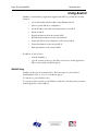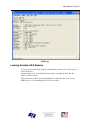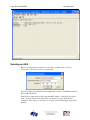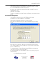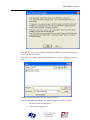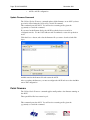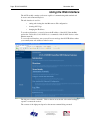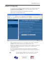
1
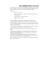
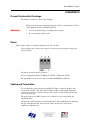
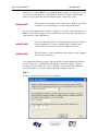
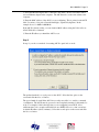
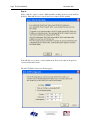
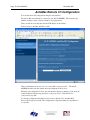
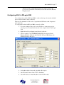
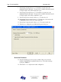
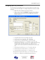
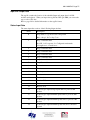
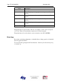
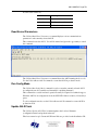
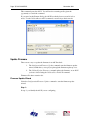
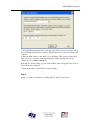
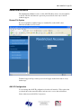
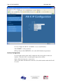
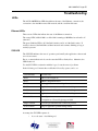
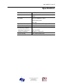
AN-X-AMXRIO
Communication Module
for Reliance AutoMax
Remote I/O
User Manual
Page 2 AN-X-AMXRIO
November 2011
Because of the variety of uses for the products described in this publication, those
responsible for the application and use of these products must satisfy themselves that all
necessary steps have been taken to assure that each application and use meets all
performance and safety requirements, including any applicable laws, regulations, codes
and standards. In no event will Quest Technical Solutions be responsible or liable for
indirect or consequential damage resulting from the use or application of these products.
Any illustrations, charts, sample programs, and layout examples shown in this publication
are intended solely for purposes of example. Since there are many variables and
requirements associated with any particular installation, Quest Technical Solutions does
not assume responsibility or liability (to include intellectual property liability) for actual
use based upon the examples shown in this publication.
Throughout this manual we use notes to make you aware of safety considerations.
WARNING!
Identifies information about practices or circumstances that can lead to
personal injury or death, property damage, or economic loss.
These warnings help to:
IMPORTANT!
TIP
•
identify a hazard
•
avoid the hazard
•
recognize the consequences
Identifies information that is especially important for successful
application and understanding of the product.
Identifies information that explains the best way to use the
AN-X-AMXRIO
Microsoft is a registered trademark of Microsoft Corporation.
Windows, Windows XP Windows Vista and Windows 7 are trademarks of Microsoft Corporation.
ControlLogix, RSLinx and RSLogix 5000 are trademarks of the Allen-Bradley Company, Inc.
AN-X-AMXRIO MODULE OVERVIEW
2
Hardware Features
3
Package Contents
3
Other Requirements
3
Modes of Operation
3
INSTALLATION
5
Prevent Electrostatic Discharge
5
Power
5
Cabling and Termination
5
Ethernet Cabling
6
Software Installation
6
ETHERNET CONFIGURATION
7
Ethernet Configuration
7
Reconfiguring an AN-X from an Unknown State
11
AUTOMAX REMOTE I/O CONFIGURATION
12
Configuration File Format
13
SCHEDULED DATA WITH A CONTROLLOGIX
16
Requirements
16
Reference
16
Configuring AN-X in RSLogix 5000
17
Configuring Input-Only Connections
Selecting the RPI
19
20
Locating the Data
Input and Output Data
Status Input Data
20
21
21
Page 4 AN-X-AMXRIO
November 2011
Error Log
22
Using RSLogix 5000 to Diagnose Problems
General Tab
Connection Tab
23
23
24
CREATING CONTROLLOGIX TAGS
25
Creating the Tag File
25
Importing the Tag File into RSLogix 5000
25
Tag File Format
26
USING ANXINIT
28
AnxInit Log
28
Locating Available AN-X Modules
29
Selecting an AN-X
30
Set AN-X IP Configuration
31
Restart an AN-X
32
AN-X Info
32
Read Kernel Parameters
33
Run Config Mode
33
Update AN-X Flash
33
Update Firmware
Firmware Update Wizard
Update Firmware Command
34
34
38
Patch Firmware
38
USING THE WEB INTERFACE
40
Remote I/O Configuration
41
Log Files
System Error Log
System Info Log
ControlLogix Log
View All Logs
42
42
42
42
42
Administration Menu
Browse File System
AN-X IP Configuration
Archive Configuration
43
43
43
44
TROUBLESHOOTING
45
LEDs
Ethernet LEDs
SYS LED
NET LED – Network Status
45
45
45
46
UPDATING THE FIRMWARE
47
Reading Version Numbers
47
AUTOMAX REMOTE I/O NETWORK
48
SPECIFICATIONS
49
SUPPORT
50
WARRANTY
51
AN-X-AMXRIO Module Overview
This document is a user guide for the AN-X-AMXRIO communications module, which
connects a computer or other device to a Reliance AutoMax Remote I/O network, using
Ethernet. The module acts as a master on the AutoMax remote I/O network.
The module:
•
Scans up to 7 slave drops
•
Supports up to 248 words of scheduled output data and up to 250 words of
scheduled input data
•
Scans AutoMax remote I/O racks and heads
•
Maintains diagnostic counters
The AN-X-AMXRIO module exchanges scheduled data over Ethernet with a
ControlLogix processor, with RPIs from 5 to 3200 ms. Refer to page 16 for details.
The AN-X-AMXRIO module has a web interface for configuration and for monitoring
operation. You can communicate with the module using any standard web browser such
as Microsoft Internet Explorer.
You can configure the module offline or online. The module can read the configuration
of the currently connected AutoMax remote I/O network and store it.
The Windows utility supplied generates tags that can be imported to RSLogix Logix
5000.
A watchdog timer is implemented in the module’s hardware. If the firmware does not
kick the watchdog within the timeout period, the watchdog times out and places the
module into a safe fatal failure state.
A jabber inhibit timer is implemented in the module’s hardware. If the network
transmitter is on longer than 150% of the longest network frame time, the transmitter is
forced off and the module is placed into a safe fatal failure state.
The module firmware can be updated over Ethernet using the Windows utility supplied.
Refer to page 47 for details.
AN-X-AMXRIO Page 3
Hardware Features
The module has:
•
LEDs to indicate the status of the connection to the Ethernet, its
own internal state, and the state of the connection to the remote I/O
network
•
an Ethernet connector
•
a 9-pin D-shell connector to connect to the AutoMax remote I/O
network
•
a power connector
Package Contents
•
AN-X-AMXRIO module
•
CD containing software and documentation
Other Requirements
To exchange scheduled data with a ControlLogix processor over Ethernet requires:
•
Version 12 or above of RSLogix 5000
•
version 12 or above of the ControlLogix firmware
•
100 Mbit/second Ethernet network and hardware. The network should use
switches, not hubs
Modes of Operation
There are three AN-X modes of operation:
•
Boot mode. The AN-X is running its low level startup firmware.
Page 4 AN-X-AMXRIO
November 2011
•
Configuration mode. This is the mode when you are updating the firmware
in the AN-X.
•
Production mode. This is the normal runtime mode of operation.
AN-X-AMXRIO Page 5
Installation
Prevent Electrostatic Discharge
The module is sensitive to electrostatic discharge.
Electrostatic discharge can damage integrated circuits or semiconductors. Follow
these guidelines when you handle the module:
WARNING!
•
Touch a grounded object to discharge static potential
•
Do not touch the connector pins
Power
AN-X requires a DC power input of anywhere from 12 to 24 VDC.
Left to right the pins on the power connector are chassis ground, negative voltage and
positive voltage.
The chassis ground should be connected.
Power consumption internally is 300 mA @ 12VDC or 150 mA @ 24VDC.
The part number for the power connector is Phoenix MSTB 2.5/3-ST-5.08
Cabling and Termination
Use a standard drop cable and passive tap M/N 57C380 to connect the module to the
coaxial network cable. The drop cable is a multi-conductor cable with 9-pin D-shell
connectors at each end. Connect one end to the connector on the module and the other
end to the passive tap.
The passive tap has two BNC connectors for connection to the coaxial cables and
terminating loads.
The network coaxial cable must be terminated with 75 ohm terminating loads attached to
the taps at the physical ends of the network. There should be two and only two
terminators on the network.
Page 6 AN-X-AMXRIO
November 2011
The cable must be RG-59/U.
Ethernet Cabling
AN-X has a standard RJ-45 connector for connecting to Ethernet.
If you are connecting AN-X to an existing network through a router or switch, use a
standard Ethernet cable.
If you are connecting directly between a computer and AN-X, use a crossover cable.
Software Installation
You must uninstall any previous version of the software before you can install a new
version. Use the Windows Control Panel Add and Remove Programs to remove the old
version.
Insert the CD supplied with the AN-X module and run the setup program on the CD.
AN-X-AMXRIO Page 7
Ethernet Configuration
The AN-X-AMXRIO module connects a computer or other device on Ethernet to a
Reliance AutoMax remote I/O network.
Before you can use the AN-X-AMXRIO to scan I/O, you must configure its Ethernet
network properties.
Ethernet Configuration
AN-X can be configured to use a static (unchanging) IP address or it can be configured to
obtain its IP address from a DHCP server.
Unless you have control of the DHCP server, in most applications you will want to
configure AN-X to use a static IP address. Otherwise the DHCP server may assign a
different IP address each time AN-X powers up, and any software that accesses the ANX module would have to be reconfigured to use the new IP address.
AN-X is shipped with DHCP enabled. If the AN-X module finds a DHCP server on the
network, the AN-X module obtains its IP address from the DHCP server. You can use the
utility AnxInit to find the IP address that the DHCP server assigned. Select
Utilities/Locate All AN-X Modules and AnxInit will locate the AN-X and display its IP
address. See page 29.
Page 8 AN-X-AMXRIO
November 2011
If AN-X does not find a DHCP server within about three minutes of starting up, it reverts
to a temporary static IP address of 192.168.0.41 If AN-X is using this temporary IP
address, it repeatedly flashes the SYS LED three times followed by a pause.
IMPORTANT!
Use this temporary IP address only for initial setup of AN-X. AN-X will
not function for its intended purpose at the temporary IP address.
If you are using multiple AN-X modules, configure one at a time, especially if there is no
DHCP server on the network, since they will all revert to the same temporary IP address
when they fail to find a DHCP server.
IMPORTANT!
If you are connecting AN-X to an existing Ethernet network, consult the
network administrator to obtain a static IP address for AN-X and to
obtain information about how you should configure AN-X and.
IMPORTANT!
The AN-X must be on the local Ethernet (same subnet as your computer)
when you set its IP address.
You configure the Ethernet properties using the Windows utility AnxInit supplied with
AN-X. You can also set the IP address through the web interface. Refer to page 43.
Use the Configuration/AN-X IP Settings command to start the AN-X IP configuration
wizard, which takes you step by step through the IP configuration process.
Step 1
In step 1, you identify the AN-X you are configuring.
AN-X-AMXRIO Page 9
1. Select the Ethernet adapter that’s connected to the AN-X. In most cases there will be
just one Ethernet adapter in the computer. The AN-X must be on the same subnet as the
computer.
2. Enter the MAC address of the AN-X you are configuring. This is printed on the AN-X
label. It consists of six pairs of hexadecimal digits, separated by hyphens. In the
example above, it’s 00-0c-1a-00-00-0a.
If the AN-X is already online, you can obtain its MAC address using the Utilities/Locate
All AN-X Modules command.
3. Enter the IP address you intend the AN-X to use.
Step 2
In step 2, you choose a method of restarting AN-X to put it in boot mode.
The preferred method is to cycle power on the AN-X. Select the first option on the
screen and click the Next >> button.
The second method, useful if the AN-X in not easily accessible, is to send it a command
over Ethernet. The AN-X must be powered on and completely running for this method to
work. For example, if this is the first time you are configuring a new AN-X, allow
sufficient time for it to acquire an IP address from a DHCP server or to time out and use
its default IP address (about 3 minutes). Select the second option on the screen and click
the Next >> button.
Page 10 AN-X-AMXRIO
November 2011
Step 3:
Wait for AN-X to enter boot mode. While AnxInit is waiting, the Next>> button will be
disabled. When AN-X is in boot mode, the Next>> button will be enabled.
If the AN-X does not enter boot mode within about 10 seconds, return to the previous
screens and check the entries.
The AN-X TCP/IP Configuration dialog appears.
AN-X-AMXRIO Page 11
Enter a Host Name for the AN-X. This name is used internally by AN-X and may be
used to identify the AN-X if you have a DNS server on your network. The name can be
from 1 to 31 characters long.
To configure the AN-X to obtain its IP address from a DHCP server on the network,
select Obtain an IP address automatically (DHCP)
To configure the AN-X to use a static IP address, select Use the following Settings and
enter:
•
the desired IP address for the AN-X.
•
the Subnet mask for the AN-X
•
the default gateway for your network.
You must enter a valid default gateway address even if there is no device at the gateway
address on the network.
Click OK to complete the configuration.
If you Cancel the Configuration/AN-X IP Settings command, AN-X is left running the
boot code. Use the Utilities/Restart AN-X command to restart the AN-X.
You can also reconfigure the AN-X IP parameters from the web interface. Refer to page
43.
Reconfiguring an AN-X from an Unknown State
It sometimes happens that an AN-X has been previously configured with an IP address
that causes it to be inaccessible on the current Ethernet network. To reconfigure it to a
known state, run the command Configuration/AN-X IP Settings to start the AN-X IP
Configuration Wizard and reconfigure AN-X.
Page 12 AN-X-AMXRIO
November 2011
AutoMax Remote I/O Configuration
You set the remote I/O configuration using the web interface.
The remote I/O network must be connected to the AN-X-AMXRIO. The ControlLogix
with the exclusive owner connection must be in program mode.
Start your web browser and enter the AN-X IP address as the address.
Select Configure AutoMax RIO Ethernet/IP.
Click on the link Automatically generate an AutoMax configuration file. The AN-XAMXRIO module reads the current network configuration and stores it.
When the autoconfiguration is done, the web interface displays a summary of the network
found and displays the message Automatic configuration done. Click the Back to
configuration page link.
To view the configuration file that has been created, click the View AutoMax RIO
Ethernet/IP Configuration link. The configuration is displayed either in a spreadsheet or
as a text file.
AN-X-AMXRIO Page 13
To view the current configuration, it may be necessary to refresh the
displayed configuration once or twice, as the browser may use a
previously cached version of the file.
TIP
To save the configuration file, right click the View AutoMax RIO Ethernet/IP
Configuration link and select Save Target as… Save the file and edit offline if you wish
to make changes.
To download a configuration file to the AN-X-AMXRIO, browse or type in the file name
in the web interface and click the Send File to AN-X button.
Configuration File Format
The configuration file is a comma separated variable (CSV) text file. You can edit or
view it with either a spreadsheet such as Excel or a text editor such as Windows Notepad.
Typically you would create the file using autoconfiguration in the web interface, then edit
it offline, and finally upload it to the AN-X using the web interface.
Lines beginning with a semicolon are comments and are ignored by the AN-X-AMXRIO
firmware when it reads the configuration.
The file consists of several sections.
AN-X Export Name
The line
ClxExp,ANX
defines the AN-X name used in RSLogix 5000. It is used only when you use the
configuration file to create tags for import into RSLogix 5000. Refer to page 25 for
details.
Drop Definitions
Each drop is defined by a line in the configuration file. The format is different for racks
and heads.
Racks
A rack definition consists of:
•
a drop identifier, for example, Drop1. This identifies the drop being defind
and should not be edited.
•
the export name, for example AmxRack1, used by the program that creates
tags for import into RSLogix 5000. Refer to page 25 for details. You can
change this to something appropriate for your system.
•
the rack adapter part number, for example 419451-001A
Page 14 AN-X-AMXRIO
November 2011
•
the starting output and input offsets in the ControlLogix scheduled data for
the drop. Drops must start on even word boundaries.
•
16 pairs of output and input slot masks for each slot in the rack. Each slot
mask consists of 16 bits. The bit is set if the corresponding register in the
slot is an input or output and is 0 otherwise.
Example:
Drop1,AmxRack1,419451-001A, 0, 0, 0xFFFFFFFF, 0x00000000, 0x00000000,
0xFFFFFFFF, …
Heads
A head definition consists of:
•
a drop identifier, for example, Drop2
•
the export name, for example AmxHead2, used by the program that creates
tags for import into RSLogix 5000. Refer to page 25 for details.
•
the head adapter part number, for example 419451-103A
•
the starting output and input offsets in the ControlLogix scheduled data for
the drop. Drops must start on even word boundaries.
•
port definitions.
For the newer 57C328 heads, there are four pairs of output and input port definitions.
The output port definition defines the state of the four possible registers for each port, O
if it’s an output, x otherwise. The input port definition defines the state of the four
possible locations for each port, I if it’s an input, x otherwise.
Example:
Drop2,AmxHead2,419451-103A,2,2, xxOx, Ixxx, xxxx, IIxx, xxxx, IIIx, xxxx, IIxI
For the older 57C330 heads, there are four port definitions. The port definition defines
the state of the four possible registers for each port, O if it’s occupied, x otherwise. The
AN-X-AMXRIO module determines whether it’s an input or output from data the head
sends at runtime.
Example:
Drop6,DropName6,419451-101A,200,200,OOxx,OxxO,OOOO,OxxO
Input and Output Sizes
At the end of the configuration file created by autoconfiguration are two comment lines
that give the output and input sizes. You can use these sizes to set the scheduled output
and input sizes in RSLogix 5000.
If you edit the configuration file, the sizes from autoconfiguration will no longer be valid.
AN-X-AMXRIO Page 15
Example
;OutLen,InpLen
;64,64
Page 16 AN-X-AMXRIO
November 2011
Scheduled Data with a ControlLogix
AN-X-AMXRIO exchanges scheduled data with a ControlLogix processor.
It supports:
•
up to 248 registers of output data
•
up to 250 registers of input data
•
24 registers of status input data
The terms input and output are from the point of view of the ControlLogix.
The ControlLogix processor sends output data to the AN-X-AMXRIO and the AN-X
sends it out on the AutoMax Remote I/O network.
The AN-X receives input data from the AutoMax remote I/O network and sends input
and status input data to the ControlLogix.
There are two possible types of scheduled connections from the ControlLogix processor
to the AN-X-AMXRIO:
•
Exclusive owner connections, which contain input, output and status input
data
•
Input-only connections, which contain input and status input data
There can be only one exclusive owner connection to an AN-X module, but there can be
more than one input only connection to an AN-X.
To configure scheduled data exchange:
1. Configure AN-X in RSLogix 5000
2. Configure the remote I/O network in AN-X-AMXRIO
3. Use the tag conversion utility provided to create a tag file from the I/O
configuration
4. Import the tags into RSLogix 5000
Requirements
•
RSLogix 5000 version 12 or above
•
ControlLogix processor with version 12 or above firmware
•
100 Mbit Ethernet network and modules
Reference
Allen-Bradley publication EtherNet/IP Media Planning and Installation Manual,
publication ENET-IN001A-EN-P
WARNING!
Do not use the web interface to monitor data on the AN-X-AMXRIO
AN-X-AMXRIO Page 17
while the AN-X is exchanging scheduled data with a ControlLogix
processor in a production environment, because this affects the Ethernet
IP update times.
Configuring AN-X in RSLogix 5000
You configure the module in RSLogix 5000 to set the module type, how much scheduled
data to transfer and how often to transfer it.
There can be a maximum of 248 words of output data and 250 words each of input and
status input data.
To configure the module in RSLogix 5000, you must be offline.
1. If you are creating a new project, select File/New to create a new project,
give the processor a name, and enter the slot it occupies in the ControlLogix
rack.
2. Right click on I/O configuration and select New Module…
3. Select a module of Type ETHERNET-MODULE, Description Generic
Ethernet Module from the list and Click OK. RSLogix 5000 displays the
Module Properties dialog box.
4. Assign the module a Name and optionally a Description.
5. Set the Comm Format to Data – INT – with Status.
6. Set the IP Address to match the address of the AN-X module.
Page 18 AN-X-AMXRIO
November 2011
7. Set the Input Assembly Instance to 1. Normally you set the size to the
maximum allowed, 250 words. You can set it to a smaller value but it should
be large enough to allow all the input data to pass.
8. Set the Output Assembly Instance to 2. Normally you set the size to the
maximum allowed, 248 words. You can set it to a smaller value but it should
be large enough to allow all the output data to pass.
9. Set the Configuration Assembly Instance to 4. Set the size to 0.
10. Set the Status Input Assembly Instance to 5. Set the size to 26, since the ANX-AMXRIO produces 26 words of status input data.
11. Set the Status Output Assembly Instance to 6. You cannot set the size.
12. Click Next > to display the second Module Properties dialog box
Connection Parameters
13. Set the module Requested Packet Interval (RPI). This is how often the
module’s scheduled data is updated in the processor. The value can range
from 5.0 to 3200.0 ms.
14. Click Finish >> to complete the module configuration.
AN-X-AMXRIO Page 19
Configuring Input-Only Connections
In a ControlLogix system, multiple processors can receive inputs from a module. Only
one processor can control the outputs. To configure an input-only connection to the ANX module:
1. Right click on I/O configuration and select New Module…
2. Select a module of Type 1756-ETHERNET, Description Generic Ethernet
Module from the list and click OK. RSLogix 5000 displays the Module
Properties dialog box.
3. Assign the module a Name and optionally a Description.
4. Set the Comm Format to Input Data – INT – With Status.
5. Set the IP Address to match the IP address of the AN-X module.
6. Set the Input Assembly Instance to 1. Normally you set the size to the
maximum allowed, 250 words. You can set it to a smaller value but it should
be large enough to allow all the input data to pass. If there is also an
exclusive owner connection, then the size should match the exclusive owner
size.
7. Set the Output Assembly Instance to be 3. You cannot set the size.
8. Set the Configuration Assembly Instance to 4. Set the size to 0.
9. Set the Status Input Assembly Instance to 5. Set the size to 26.
10. Set the Status Output Assembly Instance to 6. You cannot set the size.
11. Click Next > to display the second Module Properties dialog box.
Page 20 AN-X-AMXRIO
November 2011
Connection Parameters
12. Set the module Requested Packet Interval (RPI). This is how often the
module’s scheduled data is updated in the processor. The value can range
from 5.0 to 3200.0 ms.
13. Click Finish >> to complete the module configuration.
All connections to the module must have the same lengths and RPIs.
Selecting the RPI
When you create an exclusive owner or input only connection to the AN-X-AMXRIO,
you must select a requested packet interval (RPI), the period at which the data updates.
Consider the AutoMax remote I/O network time when selecting an RPI. There’s no
advantage in selecting an RPI that’s much faster than the network update time, since the
network data won’t update as fast as the scheduled connection. In addition, it will just
add ControlLogix backplane and Ethernet traffic.
Locating the Data
The data that is exchanged between the AN-X and the ControlLogix processor is defined
in a comma-delimited text file.
AN-X-AMXRIO Page 21
Input and Output Data
The tag file contains the location of the scheduled input and output data for all I/O
modules and registers. When you import the tag file into RSLogix 5000, you can use the
tags to refer to I/O data.
Refer to page 26 for detailed information on the tag file format.
Status Input Data
The status input data consists of the following diagnostic data.
Offset
0
Description
Drop status, 1 = good, 0 = bad or not present
Bit 1 = drop 1, bit 7 = drop 7, etc
1
Drop 1 extended status
0 = OK, 1 = No response, 2 = Configuration mismatch,
3=Length error, 4 = mask error
2
Drop 2 extended status
3
Drop 3 extended status
4
Drop 4 extended status
5
Drop 5 extended status
6
Drop 6 extended status
7
Drop 7 extended status
8
Transmit count
9
Receive count
10
Receive protocol errors
11
Receive noise
12
Receive timeout
13
Receive CRC error
14
Receive overrun
15
Receive abort
16
ControlLogix output average update time for previous 100
updates
17
ControlLogix output minimum update time for previous 100
updates
18
ControlLogix output maximum update time for previous 100
updates
19
ControlLogix output maximum update time since connection
opened
Page 22 AN-X-AMXRIO
November 2011
Offset
Description
20
Reserved
21
ControlLogix input average update time for previous 100
updates
22
ControlLogix input minimum update time for previous 100
updates
23
ControlLogix input maximum update time for previous 100
updates
24
ControlLogix input maximum update time since connection
opened
25
Reserved
The update times are given in units of 0.1 ms. For example, a value of 287 corresponds
to 28.7 ms. Times are reset when the connection is closed and reopened.
The update times refer to the exclusive owner connection to the AN-X-AMXRIO.
Error Log
Errors that occur during configuration of scheduled data or during operation of scheduled
data are logged in the AN-X.
You can view the log using the AN-X web interface. Select Log Files/ControlLogix Log
to view the log.
AN-X-AMXRIO Page 23
If the log overflows, AN-X closes the log file (enetip.0) and opens a second log file
(enetip.1) and continues to alternate between the two log files as each one fills up. Use
View All Logs to view both log files.
Using RSLogix 5000 to Diagnose Problems
You display the Module Properties dialog by right clicking on the module while online
with RSLogix 5000. This may help diagnosing some problems, especially connection
errors.
The following information is based on version 12.00 of RSLogix 5000.
General Tab
The Type should be ETHERNET MODULE Generic Ethernet Module
The Vendor should be Allen-Bradley (since it’s configured as a generic module)
The name and description are whatever you set when you configured the module.
Comm Format, IP Address and Connection Parameters should match what you set when
you configured the module.
Page 24 AN-X-AMXRIO
November 2011
Connection Tab
The Inhibit Module checkbox inhibits the module. It should not be checked for normal
operation.
The Major Fault on Controller if Connection Fails While in Run Mode checkbox causes
the module to fault the processor if the connection between the ControlLogix processor
and the module fails.
If there are any problems connecting to the AN-X-AMXRIO module, there will be an
error message in the module fault area.
AN-X-AMXRIO Page 25
Creating ControlLogix Tags
Use the AmxRioTagExport utility to create tags that can be imported into RSLogix 5000.
These tags are created as aliases. The alias name is based on the I/O address of the
remote I/O data.
If you create your ControlLogix program using these aliases and change the I/O
configuration by adding drops or modules, the offsets of the data in the AN-X-AMXRIO
scheduled data will change, but you can import a new tag file and the new aliases will
point to the new offsets. It will not be necessary to change the control program.
Creating the Tag File
To create the tag file:
1. Use the web interface to upload the configuration file from the
AN-X-AMXRIO and store it on your hard disk.
2. Edit the stored configuration file and change the module name (ModName)
to match the AN-X name in RSLogix 5000.
3. Run AmxRioTagExport.
4. Type or browse in the names of the configuration file (AmxRioCfgFile) and
the Tag Export File.
5. If you are exporting tags for import into an input only connection, check the
Input Only checkbox.
6. Click Export to create the tag file.
TIP
Upload the modified configuration file to the AN-X-AMXRIO. The
next time you perform an autoconfiguration, the AN-X will preserve the
modified module name and drop names in the new configuration file it
creates.
Importing the Tag File into RSLogix 5000
You must be offline to import tags into RSLogix 5000.
Page 26 AN-X-AMXRIO
November 2011
To import the file into RSLogix 5000:
1. Select Tools/Import Tags.
2. Browse or type in the tag file name and click Import.
Tag File Format
Tags created by AmxRioTagExport consist of six fields. They have the following
format:
TYPE,SCOPE,NAME,DESCRIPTION,DATATYPE,SPECIFIER
ALIAS,"","AmxRack1_I_00_00","","","ANX:I.Data[0]"
ALIAS,"","AmxRack1_O_04_16","","","ANX:O.Data[0]"
ALIAS,"","AmxHead2_O_0_2","","","ANX:O.Data[2]"
ALIAS,"","AmxHead2_I_0_0","","","ANX:I.Data[2]"
The Type is always ALIAS.
The SCOPE is always “” (blank).
The NAME is made up of the drop name from the configuration file and the address on
the AutoMax Remote I/O network. The address consists of I or O for input or output,
AN-X-AMXRIO Page 27
followed by the slot and offset. For example, the name AmxRack1_O_04_16
corresponds to rack 1 output, slot 4, offset 16.
You can edit the configuration file and change the default name (AmxRack# or
AmxHead#) in the ExpName field before you create the tag file.
The DESCRIPTION is created as “” (blank). You can edit this field in a spreadsheet or
text editor to create an appropriate description.
The DATATYPE is “” and should not be changed.
The SPECIFIER is the data address. Do not change it.
Page 28 AN-X-AMXRIO
November 2011
Using AnxInit
AnxInit is a 32-bit Windows application supplied with AN-X to perform the following
functions:
•
Locate and identify AN-X modules on the Ethernet network
•
Select a specific AN-X for configuration
•
Set the IP address and other network parameters for an AN-X
•
Restart an AN-X
•
Display information about the selected AN-X
•
Read the kernel parameters for the selected AN-X
•
Update the flash (low level firmware) on the selected AN-X
•
Update the firmware on the selected AN-X
•
Patch the firmware on the selected AN-X
In addition, it can be used to:
•
clear the AnxInit log
•
copy the contents of the log to the clipboard for use by another application.
This is often useful for technical support
AnxInit Log
AnxInit logs messages in its main window. These messages are often useful for
determining the cause of errors or for technical support.
To clear the log, select Edit/ClearLog.
To copy the contents of the Log to the Windows clipboard so that they can be pasted into
another application, select Edit/Copy.
AN-X-AMXRIO Page 29
AN-X Log
Locating Available AN-X Modules
To locate all accessible AN-X modules on the Ethernet network, select Utilities/Locate
All AN-X Modules.
AnxInit displays a list of the AN-X modules it finds, showing their MAC IDs, IP
addresses and host names.
This command is useful for determining IP addresses when they have been set by a
DHCP server or for confirming that an AN-X is accessible.
Page 30 AN-X-AMXRIO
November 2011
Selecting an AN-X
Before you can perform an operation on an AN-X, you must select it. Choose
Utilities/Select An AN-X to select a specific AN-X.
From the Adapter list, select the network adapter that connects to the Ethernet network
that contains the AN-X.
In the Ethernet MAC Address field, enter the MAC Address of the AN-X you wish to
select. It can be found on the AN-X label or using the Locate All AN-X Modules
command. The format is as shown above, six pairs of hexadecimal digits separated by
hyphens.
AN-X-AMXRIO Page 31
In the IP Address field, enter the Ethernet IP address of the AN-X you wish to select. It
can be found using the Locate All AN-X Modules command. The format is as shown
above, four decimal numbers each in the range 0 to 255.
Both MAC address and IP address must match the settings on the AN-X in order for
communication to occur.
Click OK to select the AN-X.
The title bar of AnxInit shows the MAC Address and IP Address of the currently selected
AN-X.
Set AN-X IP Configuration
Utilities/AN-X IP Configuration sets the AN-X IP address and hostname.
The AN-X must be on the local Ethernet to set its IP address.
First select the AN-X using the Utilities/Select An AN-X command.
Next select Utilities/AN-X IP Configuration. The AN-X TCP/IP Configuration dialog
appears.
Enter a Host Name for the AN-X. This name is used internally by AN-X and may be
used to identify the AN-X if you have a DNS server on your network. The name can be
from 1 to 31 characters long.
To configure the AN-X to obtain its IP address from a DHCP server on the network,
select Obtain an IP address automatically (DHCP)
To configure the AN-X to use a static IP address, select Use the following Settings and
enter the following:
•
the desired IP address for the AN-X.
Page 32 AN-X-AMXRIO
November 2011
•
the Subnet mask for the AN-X
•
the default gateway for your network.
You must enter a valid default gateway address even if there is no device at the gateway
address on the network.
Click OK to complete the configuration.
Utilities/AN-X IP Configuration resets the selected AN-X. Use the Utilities/Restart AN-X
to restart the AN-X in production mode.
If you Cancel the Utilities/AN-X IP Configuration command, AN-X is left running the
boot code. Use the Utilities/Restart AN-X command to restart the AN-X.
Restart an AN-X
Use the Utilities/Restart AN-X command to restart the currently selected AN-X.
AN-X Info
The Utilities/AN-X Info command provides information about the currently selected ANX in the log window.
The information shown:
AN-X Info
Ethernet MAC address
SerNum
Serial number
DaughterID
Daughterboard ID, 3 for AN-X-AMXRIO
BootRev
Boot code version
ConfigRev
Configuration kernel version
ProdRev
Production kernel version
HwRev
Hardware version
FirmwRev
Firmware release version (depends on current operating mode)
Status
see below
VendorId
Vendor ID
ProdId
Product ID
IpAddrStr
IP address assigned using Utilities/AN-X IP Configuration
HostName
name assigned using Utilities/AN-X IP Configuration
In boot mode, FirmwRev, Vendor ID and Product ID and not valid, and IpAddrStr and
HostName are not shown.
AN-X-AMXRIO Page 33
Possible status values are:
Value
Meaning
1
Boot mode
2
Configuration mode
4
Production mode
Read Kernel Parameters
The Utilities/Read Kernel Parameters command displays various communications
parameters for the currently selected AN-X
This command resets the AN-X. You will be warned and given the opportunity to cancel
the command.
The Utilities/Read Kernel Parameters command leaves the AN-X running the boot code.
Use the Utilities/Restart AN-X command to restart the AN-X in production mode.
Run Config Mode
The Utilities/Run Config Mode command is used to restart the currently selected AN-X
in configuration mode (normally used internally for updating firmware).
This command is not used in normal operation but may be required for technical support.
When the AN-X is in configuration mode, the SYS LED flashes red twice, followed by a
pause.
To exit configuration mode, use the Utilities/Restart AN-X command to restart AN-X in
production mode.
Update AN-X Flash
The Utilities/Update AN-X Flash command updates the low-level firmware
(configuration kernel and production kernel).
Files have extension qtf. Current AN-X kernel files are provided on the distribution CD.
Page 34 AN-X-AMXRIO
November 2011
This command resets the AN-X. You will receive a warning and be given the
opportunity to Cancel the command.
If you cancel at the filename dialog, the AN-X has already been reset and is in boot
mode. Use the Utilities/Restart AN-X command to restart it in production mode.
Update Firmware
There are two ways to update the firmware in an AN-X module.
1. The Configuration/Firmware Update command starts the firmware update
wizard, which takes you step by step through the firmware update process.
2. The Utilities/Update Firmware command updates the firmware on an AN-X
you have selected using the Utilities/Select An AN-X command.
Firmware files have extension bin.
Firmware Update Wizard
Select the Configuration/Firmware Update command to start the firmware update
wizard.
Step 1:
In step 1, you identify the AN-X you are configuring.
AN-X-AMXRIO Page 35
1. Select the Ethernet adapter that’s connected to the AN-X. In most cases there will be
just one Ethernet adapter in the computer. The AN-X must be on the same subnet as the
computer.
2. Enter the MAC address of the AN-X you are updating. This is printed on the AN-X
label. It consists of six pairs of hexadecimal digits, separated by hyphens. In the
example above, it’s 00-0c-1a-00-00-09.
If the AN-X is already online, you can obtain its MAC address using the Utilities/Locate
All AN-X Modules command.
3. Enter the IP address of the AN-X you want to update
Step 2
In step 2, you choose a method of restarting AN-X to put it in config mode.
Page 36 AN-X-AMXRIO
November 2011
The preferred method is to cycle power on the AN-X. Select the first option on the
screen and click the Next >> button.
The second method, useful if the AN-X in not easily accessible, is to send it a command
over Ethernet. The AN-X must be powered on and completely running for this method to
work. For example, if this is the first time you are configuring a new AN-X, allow
sufficient time for it to acquire an IP address from a DHCP server or to time out and use
its default IP address (about 3 minutes). Select the second option on the screen and click
the Next >> button.
Step 3:
Wait for AN-X to enter config mode. While AnxInit is waiting, the Next>> button will
be disabled. When AN-X is in boot mode, the Next>> button will be enabled.
AN-X-AMXRIO Page 37
If the AN-X does not enter config mode within about 60 seconds, return to the previous
screens and check the entries.
Click the Next>> button, and select the firmware file you want to download and click
Open.
AnxInit transfers the firmware file and restarts the AN-X.
After you run update the firmware, you must reconfigure the AN-X and restore:
•
Automation network configuration
•
ControlLogix configuration
Page 38 AN-X-AMXRIO
•
November 2011
AN-X to AN-X configuration
Update Firmware Command
The Utilities/Update Firmware command updates all the firmware on an AN-X you have
previously selected using the Utilities/Select An AN-X command.
This command resets the AN-X. You will receive a warning and be given the
opportunity to Cancel the command.
If you cancel at the filename dialog, the AN-X has already been reset and is in
configuration mode. Use the Utilities/Restart AN-X command to restart it in production
mode.
Click the Next>> button, and select the firmware file you want to download and click
Open.
AnxInit transfers the firmware file and restarts the AN-X.
After you update the firmware, you must reconfigure the AN-X and restore the AutoMax
remote I/O configuration
Patch Firmware
The Utilities/Patch Firmware command applies small patches to the firmware running on
the AN-X.
These patch files files have extension pch.
This command resets the AN-X. You will receive a warning and be given the
opportunity to Cancel the command.
AN-X-AMXRIO Page 39
You do not have to reconfigure the AN-X after applying a patch. All configuration
information will be left intact.
When the patch has been applied, AnxInit restarts the AN-X in production mode.
If you cancel at the filename dialog, the AN-X has already been reset and is in
configuration mode. Use the Utilities/Restart AN-X command to restart it in production
mode.
Page 40 AN-X-AMXRIO
November 2011
Using the Web Interface
The AN-X module contains a webserver capable of communicating with standard web
browsers such as Internet Explorer.
The web interface is used for:
•
setting and viewing the AutoMax remote I/O configuration
•
viewing AN-X logs
•
changing the IP address
To use the web interface, you need to know the IP address of the AN-X. Run AnxInit
and use the Utilities/Locate All AN-X Devices command to find all AN-X devices on the
Ethernet network.
To access the web interface, start your web browser and type the AN-X IP address where
you normally enter web addresses in the browser.
The left pane contains commands. Click on the arrows at the left of the main headings to
expand or contract the sections.
The contents of the right pane depend on the current command being executed.
AN-X-AMXRIO Page 41
Remote I/O Configuration
To set the remote I/O configuration using the web interface, the remote I/O network must
be connected to the AN-X-AMXRIO. The ControlLogix with the exclusive owner
connection must be in program mode.
Start your web browser and enter the AN-X IP address as the address.
Select Configure AutoMax RIO Ethernet/IP.
Click on the link Automatically generate an AutoMax configuration file. The AN-XAMXRIO module reads the current network configuration and stores it.
When the autoconfiguration is done, the web interface displays a summary of the network
found and displays the message Automatic configuration done. Click the Back to
configuration page link.
To view the configuration file that has been created, click the View AutoMax RIO
Ethernet/IP Configuration link. The configuration is displayed either in a spreadsheet or
as a text file.
TIP
To view the current configuration, it may be necessary to refresh the
displayed configuration once or twice, as the browser may use a
Page 42 AN-X-AMXRIO
November 2011
previously cached version of the file.
To save the configuration file, right click the View AutoMax RIO Ethernet/IP
Configuration link and select Save Target as… Save the file and edit offline if you wish
to make changes.
To download a configuration file to the AN-X-AMXRIO, browse or type in the file name
in the web interface and click the Send File to AN-X button.
Log Files
AN-X maintains various logs to record diagnostic and error messages. Use the Utilities
menu in the web interface to view these logs.
System Error Log
The System Error log records errors that occur during AN-X operation. This log is
normally empty.
System Info Log
The System Info Log records informational messages during startup and normal
operation.
ControlLogix Log
The ControlLogix Log records messages from the application that is responsible for
scheduled communication with a ControlLogix processor.
These messages include normal startup messages, messages about problems with the
configuration file, and runtime errors such as timeouts.
If the log overflows, AN-X closes the log file (enetip.0) and opens a second log file
(enetip.1.1) and continues to alternate between the two log files as each one fills up. Use
View All Logs to view both log files.
View All Logs
Use View All Logs to list and view all the AN-X logs. To view a log file, double click on
the file name.
AN-X-AMXRIO Page 43
Administration Menu
The Administration Menu is used to set the AN-X IP address and to view and edit files
on AN-X. The file edit function is password protected and is used only for AN-X
technical support.
Browse File System
If you are required by technical support to examine files on the AN-X, select
Administration/Browse File System.
Technical support will provide the password and supply detailed information on any
further steps.
AN-X IP Configuration
You can change the AN-X IP configuration from the web interface. This requires that
you already know the currect IP address and can use it to access the web interface.
Select Administration/AN-X IP Configuration.
Page 44 AN-X-AMXRIO
November 2011
You can configure the AN-X to use DHCP or to use a static IP address.
Click SUBMIT to set the parameters.
When prompted, click CONTINUE to reboot the AN-X with the new parameters.
Archive Configuration
You can archive all the current AN-X configuration files and log files from the web
interface. The archive file is a standard gzip compressed tar archive.
Select Administration/Archive configuration.
Click on the Archive File link and save the file. Select the destination where the file will
be stored.
AN-X-AMXRIO Page 45
Troubleshooting
LEDs
The AN-X-AMXRIO has LEDs that indicate the state of the Ethernet connection, the
connection to the AutoMax remote I/O network, and the overall module state.
Ethernet LEDs
There are two LEDs that indicate the state of the Ethernet connection.
The orange LED, labelled 100, is on if the link is running at 100 Mbits/second and is off
otherwise.
The green Link/Act LED is off if the link is inactive and is on if the link is active. If
activity is detected, the link blinks at 30 ms intervals and continues blinking as long as
activity is present.
SYS LED
The SYS LED indicates the state of operations performed by the application software and
errors it encounters.
Errors or status indication in boot mode cause the LED to flash yellow. Otherwise, the
LED flashes red.
Use the SYS LED in conjunction with the logs to locate the cause of problems.
In the following, red 3 means three red flashes followed by a pause, and so on.
SYS LED State
Possible cause
Red 2
AN-X is in config mode
Red 3
DHCP configuration failed
Red 4
Fatal application error, check logs for cause
Red 5
Application memory access violation, check logs
Red 6
Application failed, illegal instruction, check logs
Red 7
Application crashed, unknown cause, check logs
Fast red flash
Reconfiguration
Configuration of ControlLogix support failed
Single red flash
ControlLogix scheduled data connection problem
Slow red flash
script or application problem during startup
At startup, the SYS LED sequence is:
•
boot code starts – fast flashing red
Page 46 AN-X-AMXRIO
November 2011
•
boot code loads a kernel – solid red
•
if the configuration kernel is loaded, 2 red flashes followed by a pause
•
if the production kernel loads with no errors, solid green
NET LED – Network Status
The NET LED indicates the status of the AutoMax remote I/O network.
Solid green
All drops operating correctly
Solid red
One or more drops in error
AN-X-AMXRIO Page 47
Updating the Firmware
The AN-X operating software consists of several parts:
•
boot code, runs at startup
•
configuration kernel, runs when you update firmware
•
production kernel, runs in normal operation
•
application software, for AutoMax remote I/O communication, scheduled
communication with ControlLogix and unscheduled messaging
The kernels are supplied in files with extension qtf and are updated using the AnxInit
utility. Run the command Utilities/Update AN-X Flash and select the file you wish to
download. Refer to page 33 for details.
Firmware files contain the application programs for AN-X and have extension bin. They
are downloaded using the command Configuration/Firmware Update or Utilities/Update
Firmware in AnxInit. Refer to page 34 for details.
Occasionally individual patch files are released. They have extension pch and are
downloaded using the Utilities/Patch Firmware in AnxInit. Refer to page 38 for details.
Reading Version Numbers
To read the version numbers of the various software components:
Boot code
AnxInit – AN-X Info
Configuration kernel
AnxInit – AN-X Info
Production kernel
AnxInit – AN-X Info
Firmware
AnxInit – AN-X Info (version depends on current mode,
boot, configuration or production)
Individual applications
ControlLogix scheduled
communication
Web interface, ControlLogix Log
Page 48 AN-X-AMXRIO
November 2011
AutoMax Remote I/O Network
The remote I/O network can contain up to 7 drops, numbered 1 to 7. Each drop can be
either a rack or a head.
Racks
Racks consist of slots 0-15. Each slot can have up to 32 registers. A register can be
either an input register or an output register. There can be a maximum of 120 inputs and
120 outputs per rack. Input and output registers can occur in any order in a rack.
Heads
Remote I/O heads have four ports. Each port can have from 1 to 4 registers.
Heads consist of up to 16 words each of input and output data, organized as drop (1-7),
slot (0-3) and register.
There are two types of heads. On the older 57C330 heads, the location of inputs and
outputs can be identified only at runtime. On the newer 57C328 heads, the location of
inputs and outputs can be identified at configuration time.
Maximum Network Size
An AN-X-AMXRIO module can scan a network of up to 250 input words and 248 output
words. If your network is larger, you must split it into two or more networks, each
controlled by a separate AN-X-AMXRIO.
AN-X-AMXRIO Page 49
Specifications
Parameter
Specification
Function
Bridge between Ethernet and AutoMax remote I/O
network
Description
Processor: 100MHz IDT MIPS
FLASH memory: 64M
RAM: 64M
Typical Power Consumption
300 mA @ 12 VDC or 150 mA @ 24 VDC
Maximum Power dissipation
3.6W
Environmental Conditions:
Operational Temperature
0-50°C (32-122°F)
Storage Temperature
–40 to 85°C (–40 to 185°F)
Relative Humidity
5-95% without condensation
Page 50 AN-X-AMXRIO
November 2011
Support
How to Contact Us: Sales and Support
Sales and Technical Support for this product are provided by ProSoft Technology.
Contact our worldwide Sales or Technical Support teams directly by phone or email:
Asia Pacific
+603.7724.2080, [email protected]
Europe – Middle East – Africa
+33 (0) 5.34.36.87.20, [email protected]
North America
+1.661.716.5100, [email protected]
Latin America (Sales only)
+1.281.298.9109, [email protected].
AN-X-AMXRIO Page 51
Warranty
Quest Technical Solutions warrants its products to be free from defects in workmanship
or material under normal use and service for three years after date of shipment. Quest
Technical Solutions will repair or replace without charge any equipment found to be
defective during the warranty period. Final determination of the nature and responsibility
for defective or damaged equipment will be made by Quest Technical Solutions
personnel.
All warranties hereunder are contingent upon proper use in the application for which the
product was intended and do not cover products which have been modified or repaired
without Quest Technical Solutions approval or which have been subjected to accident,
improper maintenance, installation or application, or on which original identification
marks have been removed or altered. This Limited Warranty also will not apply to
interconnecting cables or wires, consumables nor to any damage resulting from battery
leakage.
In all cases Quest Technical Solutions’ responsibility and liability under this warranty
shall be limited to the cost of the equipment. The purchaser must obtain shipping
instructions for the prepaid return of any item under this Warranty provision and
compliance with such instruction shall be a condition of this warranty.
Except for the express warranty stated above Quest Technical Solutions disclaims all
warranties with regard to the products sold hereunder including all implied warranties of
merchantability and fitness and the express warranties stated herein are in lieu of all
obligations or liabilities on the part of Quest Technical Solutions for damages including,
but not limited to, consequential damages arising out of/or in connection with the use or
performance of the Product.