1
Atlantis 5
User manual
1
Atlantis 5
ANSVARSBEGRÄNSNING
All information i denna handbok har kontrollerats noggrant och bedöms vara korrekt. Emellertid lämnar Larmia
Control AB inga garantier vad gäller manualens innehåll. Användare av denna manual ombeds rapportera
felaktigheter, tvetydigheter eller oklarheter till Larmia Control AB, för eventuella korrigeringar i framtida
utgåvor. Informationen i denna handbok kan ändras utan föregående meddelanden.
Mjukvaran som beskrivs i handboken levereras under licens från Larmia Control AB och får endast användas
eller kopieras enligt licensvillkoren. Ingen del av denna bok får återges eller överföras i någon form eller på
något sätt, elektroniskt eller mekaniskt, för något som helst ändamål utan uttryckligt skriftligt medgivande från
Larmia Control AB.
COPYRIGHT
© Larmia Control AB. Med ensamrätt.
VARUMÄRKEN
MS-DOS, Windows, Windows 98, Windows NT, Windows 2000, Windows XP, Windows Vista och Windows 7 är
registrerade varumärken som tillhör Microsoft Corporation.
Andra produktnamn som förekommer i denna bok används enbart i identifieringssyfte och kan vara ägarens
registrerade varumärken.
DISCLAIMER
The information in this manual has been carefully checked and is believed to be correct. Larmia Control AB
however, makes no warranties as regards the contents of this manual and users are requested to report errors,
discrepancies or ambiguities to Larmia Control AB, so that corrections may be made in future editions. The
information in this handbook is subject to change without prior notification.
The software described in this book is supplied under licence by Larmia Control AB and may be used or copied
only in accordance with the terms of the licence. No part of this book may be reproduced or transmitted in any
form, in any fashion, electronically or mechanically, without the express, written permission of Larmia Control
AB.
COPYRIGHT
© Larmia Control AB. All rights reserved.
TRADEMARKS
MS-DOS, Windows, Windows 98, Windows NT, Windows 2000, Windows XP, Windows Vista and Windows 7
are registered trademarks of Microsoft Corporation.
Some product names mentioned in this book are used for identification purposes only and may be the
registered trademarks of their respective companies.
November 2011
Revision: 1.0.0
Contents
Basics ....................................................................................................................................................... 1
Log In ................................................................................................................................................... 1
The function keys ................................................................................................................................ 2
Objects..................................................................................................................................................... 3
What is an Object? .............................................................................................................................. 3
The menu for objects .......................................................................................................................... 5
Analog In / Measurement ....................................................................................................................... 6
Analog Out / Setpoint.............................................................................................................................. 8
Indication ............................................................................................................................................... 10
Alarm ..................................................................................................................................................... 11
Manoeuvre (Digital Control) ................................................................................................................. 13
Status of manoeuvre and indication ................................................................................................. 14
Pulse ...................................................................................................................................................... 15
Control Curve......................................................................................................................................... 16
Settings of a control curve................................................................................................................. 17
Groups ................................................................................................................................................... 19
What is a Group? ............................................................................................................................... 19
Select group (graphical- or text-based key diagram) ........................................................................ 19
Menu for the group ........................................................................................................................... 20
Alternative presentation of a group .................................................................................................. 21
Dial-up connections ............................................................................................................................... 23
Events .................................................................................................................................................... 24
Event List ........................................................................................................................................... 24
The filter window (for the Event List)................................................................................................ 25
Alarms.................................................................................................................................................... 27
Alarm List (existing alarms) ............................................................................................................... 27
Alarm status ...................................................................................................................................... 28
Acknowledge alarms ......................................................................................................................... 28
Trend Curves.......................................................................................................................................... 29
Joint Trend Curves ............................................................................................................................. 29
Trend Curves...................................................................................................................................... 31
Trend Curves for single objects ......................................................................................................... 33
Functions for Trend Curves ............................................................................................................... 33
Picture editor ......................................................................................................................................... 36
Display functions ............................................................................................................................... 36
The grid .......................................................................................................................................... 36
Zoom.............................................................................................................................................. 36
Run / Real mode ............................................................................................................................ 36
Object types....................................................................................................................................... 36
Text ................................................................................................................................................ 37
Symbol / Picture ............................................................................................................................ 37
Figures ........................................................................................................................................... 37
Overlapped page ........................................................................................................................... 37
Object properties .............................................................................................................................. 38
Visibility ......................................................................................................................................... 38
Frame & Color ............................................................................................................................... 38
Snap to / Align mode ..................................................................................................................... 38
Object edit tools ................................................................................................................................ 39
The pointer .................................................................................................................................... 39
Edit................................................................................................................................................. 39
Special properties .............................................................................................................................. 40
Motion ........................................................................................................................................... 40
Types.............................................................................................................................................. 40
Page functions ................................................................................................................................... 40
Group / Page.................................................................................................................................. 40
Format ........................................................................................................................................... 41
Archive ........................................................................................................................................... 41
Keyboard commands ......................................................................................................................... 42
Files and folders................................................................................................................................. 44
Time Schedules ...................................................................................................................................... 46
Time Schedules .................................................................................................................................. 46
Editing of Time Schedules ................................................................................................................. 47
Functions for the Time Schedule ....................................................................................................... 49
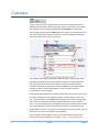
Calendar ................................................................................................................................................ 51
Editing .................................................................................................................................................... 54
Edit (plant configuration) .................................................................................................................. 54
Conditions (logic functions) ............................................................................................................... 57
Loading of the program to the CCU ...................................................................................................... 58
Misc. ...................................................................................................................................................... 60
To start and to quit ............................................................................................................................ 60
Configuration ..................................................................................................................................... 62
The Control Panel .............................................................................................................................. 62
Regulators.......................................................................................................................................... 62
Notes ................................................................................................................................................. 64
The Calculator.................................................................................................................................... 64
Last choice ......................................................................................................................................... 65
Help texts........................................................................................................................................... 65
Larmia Control ................................................................................................................................... 65
Window handling .............................................................................................................................. 65
Time and date.................................................................................................................................... 66
Basics
Log In
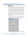
With this key function you can log in at a chosen level in the system. The
selected level is shown with the number on the key. The level determines
what permission the person has to execute different operations in the
system. It includes operations like acknowledgement of alarms, control of
operations, making and changing of drawings etc.
The function is also used when leaving and locking the system to make sure
that no unauthorized person can start operating the computer, and when log
in shall be done.
When the key is clicked a single dialog window is shown with a request to
write your password. After that click the "OK"-key or push the "Enter"-key.
The system has preset passwords to be able to authorize the administrator
to the right level of control and operation.
The lowest level of authorization is level zero and doesn’t require a
password, and the space for the password is then left empty. On the zerolevel the system is considered locked, as nothing is permitted except
checking the status of the plant. That is the same level as automatically is set
when starting up the program. If the Window-program has a screensaver
activated, the program goes automatically back to level zero when the
screen is shut down.
Please note that the password makes a distinction between capital letters
and lower-case letters, so if the password doesn’t work you should check
that the "Caps Lock"-key is not activated
1
Basics
Atlantis 5
The function keys
Key
F1
F2
F12
PRINT SCRN
2
Description
Help texts for the selected function.
Silencing of alarm sound.
Choose the last selected group.
Send picture of the screen to the printer (requires
LCCapture).
Basics
Atlantis 5
Objects
What is an Object?
An object is a position in the system. The present status (condition) of the
object is shown with text and colour. The object can be represented on the
screen by a text or by a symbol, and by clicking the name of the object an
information window shows up with information about the object, and
different choices can be made to get more information about it. Clicking the
”Menu” makes changes of the settings of the object and editions-key among
the main keys at the top of the screen.
Every object has an unique identification number to be recognized by the
system. Normally it is not necessary for the user to remember the
identification number that is done by the system itself but it is sometimes
needed when referring to a single object. This happens almost only in system
functions when setting up conditions and controls for other objects.
There are different types of objects depending on which signal the object is
going to represent. The signal can be an input or an output and be of an
analogue or a digital type. There are also other types depending on which
signal the object shall represent.
The different types of objects are:
ALARMS: Objects, which are warning when supervised objects pass into an
abnormal condition.
Flashing red/white
Remaining alarm which is not acknowledged.
Flashing grey/white
Cancelled alarm which is not acknowledged.
Permanent red
Acknowledged remaining alarm.
Permanent white
Normal (no alarm).
For further information about alarms, see section Alarm .
DIGITAL CONTROLS: Controllable objects with only two status, one active and
one passive.
3
Light blue
On.
Dark blue
Off.
Objects
Atlantis 5
When conflict alarms are used and there is no indication within the delay
time, the object will have the same colours as when an alarm from an alarm
object.
Further information about digital controls you can find in section Manoeuvre
(Digital Control).
INDICATIONS: Objects showing in which status, active or passive, the
supervised object is.
Light green
On.
Dark green
Off.
For further information about indications, see section Indication.
PULSE VALUES: Objects with an input signal varying between a high and a low
value, and counting each time the value is varying. The counter is used as a
measure of consumption over a period of time.
Brown
For further information about analogue out, see section Pulse.
ANALOGUE IN and MEASUREMENTS: Objects with a variable incoming signal
converted into a linear scale.
Yellow
Normal
When limit alarms are used and the limits are exceeded the object will have
the same colours as when an alarm from an alarm object.
Further information about analogue in you can find in section Analog In /
Measurement .
ANALOGUE OUT and SET POINTS: Objects with a variable outgoing signal
which are setting the values from a linear scale.
Purple
For further information about analogue out, see sectionAnalog Out /
Setpoint.
4
Objects
Atlantis 5
CURVES: Objects with a variable outgoing signal which is following a preset
curve for different parameters.
Purple
For further information about curve objects, see section Control Curve.
The menu for objects
To the right in the information window for an object there is a key named
"Menu", and by clicking that function a new window is showing up where
You can choose other functions for the object. There are maximum four
visible keys, and they are named Event List, Notes and Trend Curves
respectively.
By clicking the key Event List the list of events for a specific object can be
studied. A new main window is shown with an event list, which has the same
appearance as the event list for the whole system. The list is dynamically
updated and the events are assorted according to the times when they
appeared into the system. The extra functions which you can find in the
upper part of the window for choosing the date and filter are exactly the
same as in the event list for the whole system. For more information about
the functions for the event list, see section Event List .
For writing and reading information and notes concerning the object in
question the key Notes is used. Then a new program is started and will be
visible on the screen with functions for typing of text in a text editor. For
further information about this, see section Notes.
The last key, Trend Curves, is only visible when the menu belong to an analog
object. The different types of analog objects are analog outputs, set points,
measured values, pulses or curves. Trend curves are used to have an easy
overview of the changes for objects having a status, which is varying by the
time. These changes are not visible in the event lists but are shown in a timediagram. For further information about this, see section Trend Curves for
single objects .
5
Objects
Atlantis 5
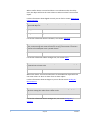
Analog In / Measurement
In the title at the top of the window is shown the type of object and the
name of it.
In the black field to the left in the window you can see the present status of
the object, the measured value and the unit. The other two narrow
rectangular fields are only visible when there are alarm limits edited for the
object. In these fields You can read the text describing the alarm limit, the
alarm limit in figures followed by the unit and at last the priority class of the
alarm.
For further information about the status of alarms, see section Alarm status.
The number, which you can read after OBJECT NO: above the black field, is
the internal identification number of the object, which is used only as a
reference of the object and control.
The number following ADDRESS: above the keys to the right is the complete
address of the object. The shortening consisting of three letters indicates to
which manufacture of the CCU the object is connected by means of
hardware, and the following figures are the exact address formatted
according to the address of the manufacture.
Below the black field to the left the group name of the object is shown. The
key marked "->" to the left is a key for direct choice of the group, which
means that if You click that key, the main window of the group to which the
object belongs will be visible on the screen.
6
Analog In / Measurement
Atlantis 5
By clicking the key Menu in the upper right corner of the window You will see
a menu from where You can get additional information about the object, as
logging of the values or notes regarding the object.
For further information about the menu, see section The menu for objects .
Below the key Menu You can see another key Ack, if the object has an
unacknowledged status. This key is used when acknowledging an alarm.
Further information about acknowledging of alarms, see section
Acknowledge alarms.
For removing of the window, the Window functions to the very upper left of
the window are used.
7
Analog In / Measurement
Atlantis 5
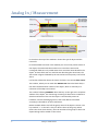
Analog Out / Setpoint
In the title at the top of the window is shown the type of object and the
name of it.
In the black field to the left in the window you can see the present status of
the object, the measured value and the unit. To the right in the black field
You can see in grey text the present control position, either "MAN" when
using manual control or "AUTO" when using automatic control. When using
manual control the object is controlled with a constant value from a
computer or a CCU, not from a main switch. When using automatic control a
computer or a CCU is controlling the regulation of the object with the
condition, regulator or object relation, which is edited for the object.
The number, which you can read after OBJECT NO: above the black field, is
the internal identification number of the object, which is used only as a
reference of the object and control.
The number following ADDRESS: above the keys to the right is the complete
address of the object. The shortening consisting of three letters indicates to
which manufacture of the CCU the object is connected by means of
hardware, and the following figures are the exact address formatted
according to the address of the manufacture.
Below the black field to the left the group name of the object is shown. The
key marked "->" to the left is a key for direct choice of the group, which
means that if You click that key, the main window of the group to which the
object belongs will be visible on the screen.
By clicking the key Menu in the upper right corner of the window You will see
a menu from where You can get additional information about the object, as
logging of the values or notes regarding the object.
For further information about the menu, see section The menu for objects.
The key Man and the following editing field in the right part of the window,
is used for manual control of the setting. For setting of a value manually for
analogue out, you start by typing a value (either with or without decimals) in
the editing field. After that you click the Man key for transferring of the
8
Analog Out / Setpoint
Atlantis 5
value. The chosen value will remain until another setting is done or until
turning over to automatic control.
The key Auto in the lower part of the window is used for the setting in
automatic operation. The text to the right of the key is informing about
which value, object or system function that is controlling the object during
automatic operation.
For removing of the window, the Window functions to the very upper left of
the window are used.
9
Analog Out / Setpoint
Atlantis 5
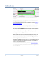
Indication
In the title at the top of the window is shown the type of object and the
name of it.
In the black field to the left in the window you can see the present status of
the object, text for indication on or off.
For further information about the status of indications, see section Status of
manoeuvre and indication .
The number, which you can read after OBJECT NO: above the black field, is
the internal identification number of the object, which is used only as a
reference of the object and control.
The number following ADDRESS: above the keys to the right is the complete
address of the object. The shortening consisting of three letters indicates to
which manufacture of the CCU the object is connected by means of
hardware, and the following figures are the exact address formatted
according to the address of the manufacture.
Below the black field to the left the group name of the object is shown. The
key marked "->" to the left is a key for direct choice of the group, which
means that if You click that key, the main window of the group to which the
object belongs will be visible on the screen.
By clicking the key Menu in the upper right corner of the window You will see
a menu from where You can get additional information about the object, as
events or notes regarding the object.
For further information about the menu, see section The menu for objects.
For removing of the window, the Window functions to the very upper left of
the window are used.
10
Indication
Atlantis 5
Alarm
In the title at the top of the window the type and name of the object are
shown.
In the black field to the left you can see the present status of the object, the
normal text or the alarm text if there is an alarm.
For further information about the status of alarms, see section Alarm status.
The number following OBJECT NO: above the black field is the internal
identification number of the object. This number is only used as a reference
of the object and control.
The number following ADDRESS: above the keys to the right is the complete
address of the object. The shortening consisting of three letters indicates to
which manufacture of the CCU the object is connected by means of
hardware, and the following figures are the exact address formatted
according to the address of the manufacture.
Below the black field to the left the group name of the object is shown. The
key marked "->" to the left is a key for direct choice of the group, which
means that if You click that key, the main window of the group to which the
object belongs will be visible on the screen.
To the right of the group name you will find an extra key marked XtraTxt, if
any extra text is edited for the object. The key is used for showing an extra
alarm text for the object with a simple text editor. For example if a special
routine has to be performed when there is an alarm from the object, and
there is not space enough for the text in the black field.
By clicking the key Menu in the upper right corner of the window You will see
a menu from where You can get additional information about the object, as
events or notes regarding the object. For further information about the
menu, see section The menu for objects.
The key Ack to the right in the window is used for acknowledgement of the
alarm of an object, which is still not acknowledged. Even if the alarm is
cancelled, the object has to be acknowledged to return to normal status.
11
Alarm
Atlantis 5
When the object is acknowledged, the key disappears and will not be visible
until there is a new alarm for the object. Further information about
acknowledgement you will find in section Acknowledge alarms.
12
Alarm
Atlantis 5
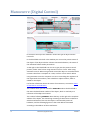
Manoeuvre (Digital Control)
In the title at the top of the window is shown the type of object and the
name of it.
In the black field to the left in the window you can see the present status of
the object. If the object also has a direct connected indication, the status of
the indication follows within parenthesis.
To the right in the black field You can see in grey text the present control
position, either "Man" when using manual control or "Auto" when using
automatic control. When using manual control the object is controlled with a
constant value from a computer or a CCU, not from a main switch. When
using automatic control a computer or a CCU is controlling the regulation of
the object with the condition, time schedule or object relation, which is
edited for the object.
For further information about the status of manoeuvres, see section Status
of manoeuvre and indication.
The number which you can read after OBJECT NO: above the black field is
the internal identification number of the object, which is used only as a
reference of the object and control.
The number following ADDRESS: above the keys to the right is the complete
address of the object. The shortening consisting of three letters indicates to
which manufacture of the CCU the object is connected by means of
hardware, and the following figures are the exact address formatted
according to the address of the manufacture.
13
Manoeuvre (Digital Control)
Atlantis 5
Below the black field to the left the group name of the object is shown. The
key marked "->" to the left is a key for direct choice of the group, which
means that if You click that key, the main window of the group to which the
object belongs will be visible on the screen.
By clicking the key Menu in the upper right corner of the window You will see
a menu from where You can get additional information about the object, as
events or notes regarding the object.
For further information about the menu, see section The menu for objects.
The keys ON and OFF in the right part of the window are intended for
manual operation of the manoeuvres. The selected manoeuvre will remain
until another one is chosen. Note that a forced stop has a higher priority
than manual manoeuvres, and that manual operation doesn't control the
manoeuvres as long as the forced stop is active.
The key Auto in the lower part of the window is used for changing over to
automatic operation. The text to the right of the key is informing about
which object or system function that is controlling the object during
automatic operation.
For removing of the window, the Window functions to the very upper left of
the window are used.
Status of manoeuvre and indication
The status of the manoeuvre of the object is shown by text and color.
Object type
MANOEUVRE:
INDICATION:
14
Status
On
Off
On
Off
Manoeuvre (Digital Control)
Color
Light blue
Dark blue
Light green
Dark green
Atlantis 5
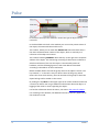
Pulse
In the title at the top of the window is shown the type of object and the
name of it.
In the black field to the left in the window you can see the present status of
the object, the measured value and the unit.
The number, which you can read after OBJECT NO: above the black field, is
the internal identification number of the object, which is used only as a
reference of the object and control.
The number following ADDRESS: above the keys to the right is the complete
address of the object. The shortening consisting of three letters indicates to
which manufacture of the CCU the object is connected by means of
hardware, and the following figures are the exact address formatted
according to the address of the manufacture.
Below the black field to the left the group name of the object is shown. The
key marked "->" to the left is a key for direct choice of the group, which
means that if You click that key, the main window of the group to which the
object belongs will be visible on the screen.
By clicking the key Menu in the upper right corner of the window You will see
a menu from where You can get additional information about the object, as
logging of the values or notes regarding the object.
For further information about the menu, see section The menu for objects.
For removing of the window, the Window functions to the very upper left of
the window are used.
15
Pulse
Atlantis 5
Control Curve
In the title at the top of the window is shown the type of object and the
name of it.
In the black field to the left in the window you can see the present status of
the object, the measured value and the unit. To the right in the black field
you can see the present control position in grey text. For curve objects there
is always the text "Auto", as manual control of curve objects is not relevant.
The number, which you can read after OBJECT NO: above the black field, is
the internal identification number of the object, which is used only as a
reference of the object and control.
The number following ADDRESS: above the keys to the right is the complete
address of the object. The shortening consisting of three letters indicates to
which manufacture of the CCU the object is connected by means of
hardware, and the following figures are the exact address formatted
according to the address of the manufacture.
Below the black field to the left the group name of the object is shown. The
key marked "->" to the left is a key for direct choice of the group, which
means that if You click that key, the main window of the group to which the
object belongs will be visible on the screen.
By clicking the key Menu in the upper right corner of the window You will see
a menu from where You can get additional information about the object, as
logging of the values or notes regarding the object.
For further information about the menu, see section The menu for objects.
The key Auto in the lower part of the window is used for the setting in
automatic operation. The text to the right of the key is informing about
which system function that is controlling the object during automatic
operation.
The key "->" in the lower right part of the information window is the key for
changing of the setting of break points and gradient of the curve. More
information about this you can find in section Settings of a control curve.
16
Control Curve
Atlantis 5
For removing of the window, the Window functions to the very upper left of
the window are used.
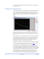
Settings of a control curve
To change the gradient and the breakpoints of a curve object graphically, the
key "->" in the lower right part of the window for a control curve is used.
When clicking this key a new window shows up, showing the present curve in
a diagram with the limit values and breakpoints which are edited for the
object.
Originally the window consists of a black field with a diagram to the left, a
key named Edit in the upper right corner and a field for editing below to the
right.
In the diagram you can see the present edition of the curve with breakpoints
and limit values for different X and Y values. The curve has a yellow colour,
and the changable break- and limit values are marked with white squares
placed on the curve. Next to the squares you can read the exact X and Y
coordinates for the break- and limit points in green colour.
The diagram is covering the area within the limits of the edition. To increase
the area you have to choose new values for the limits in the editing function.
For more information about editing of objects, see section Editing.
To change the position of the breakpoints, end values and gradient of the
curve, you have to click the editing key. When doing this another three keys
show up below the Edit key, and also two keys to the right of the editing field
in the lower right corner of the window. The shape of the curve is changed
by clicking the mouse on one of the white squares of the break- or limit
points, keep the key of the mouse pressed down and move the mouse
marker to the new position. This procedure has to be repeated until the
17
Control Curve
Atlantis 5
shape of the curve is to your satisfaction, and after that you click the key
Save to the right in the window. If you regret, and want to keep the original
shape of the curve which you had at the last saving or when the window of
control curves appeared, then you click the key Cancel.
There is also a possibility to transfer the whole curve upwards or
downwards. For this purpose You are using the two keys to the very right
below and the editing field to the left of the keys.
To transfer the whole curve one unit upwards you click once on the key to
the right marked "+". That will be marked in the editing field as the figure
shown there will be increased by one unit, but the curve in the diagram will
stay in the same position. To lower the whole curve one unit you click the
left key marked "-" once. That will be marked in the editing field as the
shown figure will decrease by one unit, but the curve in the diagram will stay
in the same position. You can also click the editing field directly and type the
wanted value.
When the wanted values for the transferring of the curve are set, You can
either choose the key Save for saving of the settings, or the key Cancel if You
want to keep the values which were set before the last saving or when the
window of control curves appeared. When the changes are done the CCU has
to be restarted. See section Loading of the program to the CCU.
18
Control Curve
Atlantis 5
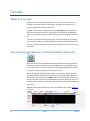
Groups
What is a Group?
All objects are divided into groups, where a group normally consists of a
building, a ventilation room, a sub central, a drawing of the process or a
group of objects with similar assignment.
A group is selected by clicking the main key Select Group. All the groups in
the system will then be shown in graphical- or text-mode (in alphabetical
order) in the window. Click the name of the group, and the group will show
up.
You can also directly find the group, which an object belongs to by clicking
the name of the object. Then the window with the object information will
show up, and by clicking the arrow you will automatically reach the group of
the object.
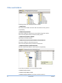
Select group (graphical- or text-based key diagram)
With this key function a separate window is shown where all the groups in
the system are presented. Choose the wanted group by clicking the mouse
on the group, and a new main window is coming up showing all the objects
in the group, presented with a picture if there is any.
When the window showing all the objects in the group is visible, there are
also some additional functions to choose at the top of the group window. To
the very left you will find the key Menu. When clicking this key you will see a
menu, from where you can have additional information about the group, for
example events and notes, or design a drawing and show graphical objects of
the group.
Additional information about the menu you will find in the section Menu for
the group.
19
Groups
Atlantis 5
The next key is named Picture or Text, and with this key you can choose
between having a schematic picture showing how the objects in the group
are connected to each other, or just to see the objects listed in writing in the
window. The name of the key is alternating into "Picture" when the objects
are presented in a list, and into "Text" when the objects are shown in a
picture. When choosing a presentation by text there is more information
about each object than in a picture.
With the two keys marked with arrows ("<-" and "-> ") you can quickly
navigate from one group to another in the system, in alphabetical order.
The next extra function you will find is a text with an arrow to the right. By
this function you can choose alternative presentations of the information
about the objects in the group. The alternatives you can find in a list box by
clicking the arrow. More information about alternative presentation you will
find in the section Alternative presentation of a group.
If any object in the group is connected to a CCU by a dialing up modem, there
are additional functions in the key bar at the top of the main window. See
section Dial-up connections for more information about the functions for
dialing up CCU.
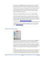
Menu for the group
To the upper left in the main window for a group you find the key Menu. By
clicking that key a new window will show up containing four keys with
functions for the groups. By using the first key you can look at the event list
for the objects only within one group, and the next key gives you a window
for notes where you can write and read information regarding the group. By
clicking the third key you will have statistics for the objects in the group, and
the last key is for editing of dynamics and designing of drawings for the
group.
The event list for objects belonging to one and the same group appears when
clicking the key Event List. This main window with the event list looks the
same as the event list for the whole system. The list is dynamically updated
and the events are assorted according to the times when the events were
20
Groups
Atlantis 5
registered. The additional functions at the upper part of the window for
selecting of the date and filter are exactly the same as for the event list for
the whole system. For more information about the functions for the event
list, see section Event List.
To have the possibility to write and read information and notes about the
group you choose the key Notes. Then a new program is started with
functions for typing of text in a text editor. For more information about how
to write information, see section Notes.
If you want to make a schematic drawing etc. for the group and to change
the position of the dynamics, you choose the key Picture Edit. When this key
is clicked more keys with more functions will be visible in the main window
of the group. One of these keys gives you support about how to place new
dynamics and how to place dynamics as symbols. More information about
the functions of the keys, see section Picture editor.
If you regret and want to remove the choice in the menu, the Window
functions to the upper left in the menu window are used.
Alternative presentation of a group
In the middle of the upper part of the window there is a list box. Click the
arrow to the right of the text and choose the type of information, which you
want to be shown on the main window of the group.
• If you choose Status every object in the window will be presented with the
present status, by showing the status text, which is edited to the status
positions. This is the normal operation situation.
• If you choose Address the complete address for every object in the window
will be shown, starting with a shortening consisting of three letters showing
to which manufacture of the CCU the object is connected concerning
hardware. The following figures are the exact address number formatted
according to the address of the manufacture.
• If You choose LED Number every connection of the objects to the LED:s on
the front of the CCU will be shown in the group window. To which CCU the
object is connected is shown by it’s address. (Only valid for Larmia Control
CCU LS920).
21
Groups
Atlantis 5
• If you choose Delay the delay of every object will be shown in the window
of the group. The delay relates to the time in minutes and seconds before
activation after a change of the status, and refers to the delay within the PC.
(For objects belonging to the Larmia Control DUC LS920 there is no delay
within the PC but refers to the delay within the CCU).
• If You choose NO/NC every object is showing its activation at either a
closing or breaking input with NO (Normal Open) for activation when there is
a closing at the input and with –NC (Normal Closed) for activation when
there is a break at the input. The minus sign in front of NC has no formal
significance but is only for better clearness. (For objects belonging to other
CCU-manufactures than LS920, the function, which is edited for the object, is
valid – there is no connection to or control of the object at the CCU showing
if the object is wrongly edited).
• If you choose Text On the text for every activation-position of the digital
objects will be shown in the window of the group, and for alarm objects the
alarm texts will be shown. This doesn’t concern the analogue objects if they
don’t have alarm limits edited.
• If you choose Text Off the text for every deactivation-position of the digital
objects will be shown in the window of the group, and for alarm objects the
normal positions will be shown. This doesn’t concern analogue objects.
• If you choose Object Number the individual index number of the object will
be shown in the window of the group. This index number is mainly used
when referring to other objects in system-functions and conditions. For more
information, see section System Functions.
The system returns to show "STATUS" after the screen saver has been
activated. This happens automatically without any keyboard instruction.
22
Groups
Atlantis 5
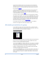
Dial-up connections
A connection between the SCADA and the CCU can be of two types when a
modem and a telephone line is used. The connection can be permanent or
configured in a way that the CCU will dial up at certain occasions. This is
called to have a Dial-up connection, and is mostly configured so that the CCU
is calling up the SCADA when an alarm is activated. Connection with the
SCADA can also be requested in order to pick up information and change
settings.
When the main window shows a group with an object belonging to a CCU,
which is connected, with the SCADA by a dial-up modem, there is another
button available at the upper part of the main window.
To dial the CCU simply click on Call. When a connection is established the
text on the button will change to Hang Up. To disconnect, simply click this
button.
The connection is established with a preset time of 300 seconds. If the time
of connection begins to run short, click Extend Time to extend the time with
another 300 seconds. This function can be utilized several times until the
needed maximum time of connection is reached.
The remaining time of the connection to the CCU is shown in the status bar
of the window, and is counted down until disconnection.
23
Dial-up connections
Atlantis 5
Events
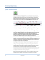
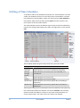
Event List
With this key function a window is shown with a list of all the events in the
system. The list is dynamically updated and the events are sorted according
to the time when they were registered by the SCADA, while the time is set
when the event was registered by the CCU.
Except for the functions at the very top of the event list, the content has the
same functions as a normal group window. If You click the line for a single
object a small window is shown with further object information, where You
among other things can go on to the objects home group or manually control
the object.
At the very upper left is an editing field showing the date from which the list
will start showing events. In this field you can choose another date to be able
to see the events on that date. Today’s events are normally always shown.
Click the editing field, write the desired day and click the "Enter"-key. The list
for the chosen date is now shown.
On the right side of the editing field is a "-" and a "+"- key. With these keys
you can quickly go one day backwards or forwards without changing the date
in the editing field.
The next group of functions at the very top of the window are the "Page"-key
and another "-" and "+" -key. With these keys you can go backwards or
forwards one page to look at the events. When doing this the date in the
editing field to the left is also changed.
In the middle upper part you can read Latest with a marking-square to the
left. If you click on the text or in the square you are marking if the
presentation shall be dynamically updated or not. This means that if a new
event is coming into the system, the event will be added to the list and
automatically shown, even if you for the moment are looking at another
page. If you don’t have the "Latest" marked you will not observe when a new
event appears. The events will of course be registered anyways so that no
24
Events
Atlantis 5
events are lost but will be shown when "Latest" is marked again, or when the
event list is viewed next time.
The Filter key to the very upper right of the window is used for filtering of
events from the event list. For more information about filtering of events,
see section The filter window (for the Event List).
The key Abort search to the very upper right in the window is only shown
when the database is searched through for new events to show. Searching in
the database can sometimes take longer time- especially when filtering is
used – and can with this function be stopped when the wanted information
is already shown. When the searching has been stopped or is ready, new
functions can be chosen.
To remove the window the Window-function at the very upper left corner is
used.
The filter window (for the Event List)
This window is shown when choosing the Filter key when looking at the
event list. In the window You will find functions to filter special events from
the list. It is only the viewed events which are filtered, and no matter how
the filtering is done, no events will be erased from the system. All events can
be seen again as soon as the filtering is interrupted.
By clicking the Alarm key, all events concerning alarms are filtered from the
event list. There are different numbered squares for marking, if You only
want to filter alarms with certain priority.
• When marking the square for Alarm all events concerning alarms are
filtered.
• When marking the square for On all activations of alarms are filtered from
the event list.
• When marking the square for Return all cancelled alarms are filtered from
the event list.
• When marking the square for Ack all acknowledgements of alarms are
filtered from the event list.
• When marking the squares for A - 0 all events concerning alarms with the
corresponding priority are filtered from the event list.
25
Events
Atlantis 5
Below the field for filtering of alarms there are another three squares for
marking where You can filter other events, and two keys.
• When marking the square for Man all events concerning on/off-control of
digital objects are filtered from the event list.
• When marking the square for Ind all events concerning on/off-control of
indications of objects are filtered from the event list.
• When marking the square for Misc all other events are filtered from the
event list, for instance system events as logging in and print out.
When clicking the key Reset all the markings in the squares in the field for
filtering are removed, and all events in the event list are shown again.
When clicking the key Save all existing markings and settings are saved, and
next time when the event list is shown the settings will be intact and the
same type of events will be filtered.
The keys Ok and Cancel executes respectively cancels the changes which are
chosen, and remove the filter window.
To remove the window the Window-function at the very upper left corner is
used
26
Events
Atlantis 5
Alarms
Alarm List (existing alarms)
When clicking this key function a window is shown with all the existing
alarms in the system. The list is updated dynamically and the alarms are
assorted according to priority. The key is also changing appearance when
new alarms are entering the system, as the key with red text is showing the
alarm with the highest priority of the alarms still not acknowledged. This
gives the possibility of a quick observation when a new alarm is coming into
the system.
Except from the extra functions at the very top of the alarm list window, the
contents have the same functions as a window for a normal group. When
clicking on the line for a single object a small window is shown with further
object information, where You among other things can proceed to the home
group of the object or acknowledge the object . See the section about Select
group (graphical- or text-based key diagram) for more information about
these functions
At the very top at the left of the window is the key "Multi Ack". With this key
you can acknowledge all present unreset alarms in the system, the active
alarms as well as the previous alarms.
Further information about acknowledgement of alarms, see section
Acknowledgement of alarms.
When the configuration is set to give an alarm signal when a new alarm
appears into the system, You stop the alarm sound with the key "Silence".
The sound can also be stopped by acknowledging the object or by pushing
the "F2"-key on the keyboard.
To remove the window the Window-function at the very upper left corner is
used.
27
Alarms
Atlantis 5
Alarm status
The alarm status of an object is shown by text and color.
Alarm status
Unacknowledged
remaining alarm
Unacknowledged
cancelled alarm
Remaining alarm
Normal
Color
Flashing red/white
Priority
Highest
Flashing grey/white
Permanent red
The normal color of the
object
Lowest
Acknowledge alarms
To acknowledge an alarm signal you choose the main key Alarm List and
then click the key Silence.
For acknowledgement of a single alarm you choose the object, which shall be
acknowledged by clicking the text of the name of the object. After that you
click the key Ack. When the object is acknowledged the key disappears and
will not be visible until there is a new alarm for the object.
For acknowledgement of all the alarms in the system you choose the main
key Alarm List and after that the key Multi Ack.
If the system is configurated to use signatures for acknowledgement, a
simple editing window will show up and request the user to write his
signature. If the signature is not approved for acknowledging of the object,
the object will remain unacknowledged and a sound signal can be heard
from the computer.
28
Alarms
Atlantis 5
Trend Curves
Joint Trend Curves
When choosing the key Trend Curves, on the speed bar at the top of the
window in the operation program, a new main window is shown where it is
possible to show several trend curves in the same diagram. This window
differ from the window showing the trend curve for a specific object, as You
here also have a list box and a key named Preferences to the upper right.
In the list box, which in the beginning is empty, different diagrams are
collected, consisting of trend curves for a group of objects. When a diagram
is made the title is shown in the list box, and by clicking the list box you can
see the whole contents of it and you can choose one of the diagrams by
clicking the title. This gives the possibility to collect several objects of the
same type in different diagrams, and to view different types of trend curves
for objects. For example the control of shunt valves for ventilation in
different fan-rooms can be collected in one diagram, and the temperatures
for supply air to different sections can be collected in another one.
When you have chosen a diagram, all curves belonging to it are shown in the
window. To choose the objects, which shall be presented in the diagram, you
click the key "Preferences" and a dialogue-window is shown for marking of
the objects and the colours of the diagram.
The dialogue window consists of a space for editing of the title, three keys
for the colours of the diagram, colours of the trend curves, two keys for
adding or removing of objects, one square for marking if the trend curve
shall be visible and three lines for object information. Below there is also a
key named "Close" to save the changes and to remove the window.
In the space for "Title" the title of the present trend curves are entered. This
is the title, which later on will be shown in the list box in the upper part of
the diagram window when choosing a diagram.
With the three keys following "Colour" You can change the colours of the
background of the diagram, the grid and the rectangle for zooming in
29
Trend Curves
Atlantis 5
respectively. If any of the keys is clicked the object will change colour. Go on
clicking until the wanted existing colour appears.
There are eight different choices of colour for the trend curves in the
diagram. By choosing one of the eight numbered keys you are choosing that
colour for the specific object, which name is shown as the last one on the list
shown in the window. Maximum eight trend curves can be shown in the
same diagram.
With the key "Add selected object" a new object can be added to the
diagram, or an existing connection between objects can be changed. To be
able to add an object it must be an open information window for an
analogue object visible on the screen. Such a window will open when an
object is clicked in a group function window, and it will remain open until it
will be closed by clicking the system function in the Window-programme to
the upper left of the screen.
When the information-window of an object is open and the key "Add
selected object" is clicked the object will be added to the diagram with the
colour, which is chosen, from one of the numbered keys following "Curve"
above. If the latest chosen colour already has been used for another object,
that object will be erased before the new object will be added.
To remove the display of an object from the diagram the key for the colour
of the object (one of the keys following "Curve") is clicked, and after that the
key "Remove curve" is clicked. The display of the object disappears from the
diagram and the colour can be used for another object.
The marking square "Show" is used if the trend curve of the chosen object
shall be shown in the diagram or if it shall be temporarily hidden. To hide
trend curves might be practical in order to show curves, which is difficult to
visualize among other curves or to utilize the auto scale optimally.
Hint!
To add trend curves for objects in new diagrams it’s easier if You have two
main windows open side by side. In one of the windows You can have the
trend curves and in the other one You can change between groups to pick
up objects. When the object that you want to add in the diagram is visible
in the group window, You click it to make the information window for that
object visible. After that You change to the window for the trend curves
and choose the colour of the curve and click "Add selected object". If You
want to add more objects You go back to the group window and pick up
the next object etc.
To work with more than one main window open, see section Window
handling.
30
Trend Curves
Atlantis 5
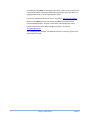
Trend Curves
With this key function a window is shown with graphs representing trend
curves for the objects. To use curves and diagrams to show the course of
events and how the control has been executed for an object, is easy and
comprehensibly. Furthermore it is a quick way for troubleshooting of the
control of the objects, as there are possibilities of zooming the trend curves
at different times.
The ATLANTIS SCADA software offers trend curves for all objects of analogue
type - analogue in, analogue out, set points and measuring points – with the
exception of curve objects. The course of events for digital- and pulse-objects
can’t be visualized by trend curves of the operation program.
In the operation program there are two ways of viewing the trend curves for
objects. There is a joint presentation where curves for several objects can be
shown in the same diagram, or curves for a specific object can be shown
separately. To show the trend curves for several objects you choose the key
"Trend curves" which you can find on the speed bar for general functions at
the very top of the window. The menu is shown when clicking the Menu key
on the same speed bar. To show the trend curves for one object you click the
key for Trend Curves which you can find on the menu for objects. The menu
is shown when clicking the "Menu"-key in the information window for the
object. The joint presentation makes it possible to compare curves for
several objects and during the same period of time, for example to compare
CCU:s in different buildings or to check which effect a specific regulation
have on adjacent objects. For more information about using trend curves for
several objects, see section Joint Trend curves.
To be able to save the measuring values the object has to be preset for this
purpose, which is done by choosing Edit in the submenu of Menu on the
speed bar at the very top of the window. The registrations of measuring
values are activated in the editing of objects. For more information about
editing of the system, see section Edit.
When trend curves are chosen for an object a new main window is opened,
with a black diagram covering most part of the window and a few keys on
top of it.
31
Trend Curves
Atlantis 5
The green curve in the diagram is showing how the values have fluctuated
during the period of time, which is indicated on the time-axis. You find the
grading of the time-axis in the lower part of the diagram, with a rastersupport at every grade. Below the diagram you also find the total period of
time and the date.
On the left side of the diagram is the grading for measured values of the
object. At the very lower left of the diagram you can read the value of the
position of the mouse, followed by the unit of the value. This value can be
practical to use as you can’t read an exact value by using only the rastersupport.
In some cases you can also see a white rectangle in the diagram-window.
This rectangle is used together with the zoom functions to change the period
of time in the diagram.
For more information about zoom functions and other functions which are
available with the keys above the diagram, see section Functions for Trend
Curves, where You also find information about the function for showing
several curves at the same time.
32
Trend Curves
Atlantis 5
Trend Curves for single objects
To show the trend curves for a specific object you choose the key Trend
curves which you find in the menu for objects. The menu will show up by
clicking the key Menu in the information window for the specific object.
When this key is activated a new main window with a black diagram is
shown. For more information about the diagram, see section Trend Curves.
In the upper part of the window for trend curves there are keys with
functions for visualization and presentation of the trend curves
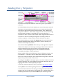
Functions for Trend Curves
In the upper part of the main window for trend curves there are keys to
select the presentation.
The keys are divided into three groups. The group to the left is named Year,
the group in the middle is named Zoom and the group to the right is named
Move. The first two groups have two keys each and the group to the right
has four keys. If a presentation of several objects at the same time in the
diagram is chosen, there are also a list box and a key named Preferences to
the right.
Below the three groups of keys there are four squares for marking named
Auto Scale, Bold Curves, Filter Off and Analyze. With these functions the
diagram and the curve can be manipulated to make the course of events
more clear.
If the joint presentation of curves for different objects is chosen by the key
Trend Curves in the speed bar at the very top of the window, there are also a
list box and a key named Preferences. See section Joint Trend curves for
more information.
The first group of keys to the far left named "Year" consists of two keys with
the signs "+" and "-". With these keys you choose presentation of values of
the object for the next or the previous year respectively. The selected year is
shown within parentheses below the diagram.
The group in the middle named Zoom is also consisting of two keys named In
and Out. By using these keys you can change the time scale in the diagram.
You can zoom in – show a shorter period of time, or you can zoom out –
show a longer period of time. The periods of time are preset on certain
33
Trend Curves
Atlantis 5
intervals, and every click on the in- or out-key make a change of one step in
the respective direction.
The available periods of time for the time-axis are:
Period
1 year
1 month
1 week
24 hours
1 hour
Raster
Raster support at every month.
Raster support at 24 hours.
Raster support at 24 hours.
Raster support at every hour.
Raster support at every minute.
When using the zooming function you choose the period of time, which you
want to zoom by applying the white rectangle over that period on the timeaxis. To zoom another period you move the white rectangle to the wanted
period by clicking the mouse on that period in the diagram. It is also possible
to move the rectangle by pushing the mouse with the cursor inside the
rectangle, and keep the button down and at the same time move the
rectangle to the wanted position.
The group of keys to the right is named Move, and these keys make it
possible to move the start- and stop-time for the period of time in the
diagram in a simple way. The group consists of four keys marked with one or
two arrows to the left and to the right. By clicking once on one of the keys
with one arrow the diagram is moved one step in the wanted direction,
keeping the scale of the raster-support. By clicking one of the keys with two
arrows the diagram is moved one complete period of time in the wanted
direction. The time or date, which is the last one, will appear in the beginning
of the time-axis of the diagram if the right key with two arrows is clicked, and
reversed for the left key.
The marking square Auto Scale is marked when the diagram automatically
shall apply the scale for the y-axis, the axis for values, to cover the area
between the highest and the lowest value. This makes it possible to study
the fluctuation of the curve. If the marking square is not marked, the scale on
the y-axis is applied to show the area between the highest and the lowest set
points for the object, according to what is edited for the object.
The marking square Bold Curves doubles the thickness of the line of the
curve. This function can be useful when doing a print out to make it easier to
observe a particular curve, or to make a curve more visible when the
resolution on the screen is high.
The marking square Filter Off is used to level the highest and lowest points
of the curve and to soften it. This is used to make it easier to study the
fluctuations and trends of the object. Please note that the algorithm for
softening of curves only affects extreme tops and glens, which not can be
classified as temporary. Curves, which have many short little spikes, are
ignored, as softening of these spikes doesn't give any visible effect.
34
Trend Curves
Atlantis 5
When clicking the marking square Analyze, the maximum-, minimum- and
average-value will be marked in the diagram.
35
Trend Curves
Atlantis 5
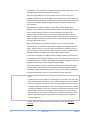
Picture editor
Display functions
The grid
• Display grid: Activates / deactivates the grid display.
• Snap to: Snaps the objects against the grid.
• + / - : Increase / decrease the grid.
Zoom
• You can select objects and zoom them in.
• Fit all objects into the display.
• Scale 1:1 : Resets the zoom factor to 1 (normal display).
• + / -: Increase / decrease the zoom.
Run / Real mode
• Run: You don't need to exit the editor to select the object dialog or test the
picture. Just press this button and you’re in real mode, press again and
you’re back in edit mode.
Object types
The editor has two kind of main object types:
Static: When an object is static it isn’t connected to any CCU-object, its only
purpose is just for graphical presentation, for example a sensor symbol.
Dynamic: The object is connected to a CCU-object and behaves after that,
depending after the type you’ve chosen.
36
Picture editor
Atlantis 5
Text
Following types are available:
Static, Dynamic, Timeschedule, Goto Group, Shortcut to file, Run event.
Symbol / Picture
Following types are available:
Static, Dynamic, Timeschedule.
With Atlantis 5 a Symbol Library is automatically included on every
session/edit.
You can build up a whole picture with this library or create your own library
made up with bitmap pictures. Or you can paint on an ordinary bitmap
background and don’t use the library at all. Usually, making a picture with
the Symbol Library is much faster than drawing the whole “display scene” on
a big bitmap.
It’s your own preferred taste how you want to edit the picture.
Figures
You have the following types:
Static: Line, Triangle, Rectangle & Circle.
Dynamic: Triangle, Rectangle & Circle.
Overlapped page
You can display other pages on the present page.
For example: If you want an overview of a couple of other pictures, you can
put them all together to form a new picture just by selecting the desired
pages and show them all at the same time.
See the overlapped page like a visual form of a Windows shortcut.
37
Picture editor
Atlantis 5
Object properties
Visibility
• Visible: Disable this if you want to hide something visual.
• Locked: You can lock an object so you don’t do the mistake of moving or
resizing it. You can unlock it if just press once the object.
• Private: Object’s that are in private mode down get converted to the
Avalon-CCU or the WEB.
• Floating: Use this function when you don’t want to get the object affected
by the zooming factor or picture position. It always going to stay at the same
position. This function is usually desirable when you have a menu system.
Frame & Color
• Frame: The thickness of the frame.
• Colour 1: Colour on frame left/up.
• Colour 2: Colour on right/down.
• Background: The background colour. You can even change the background
colour.
• Transparent: Transparent mode. On symbols you first must choose which
colour will get transparent with the background colour.
Snap to / Align mode
• Select where the object will snap to the grid.
38
Picture editor
Atlantis 5
Object edit tools
The pointer
You can use the pointer tools on one or many selected objects at the same
time.
Just press and drag on an empty region and you can select many objects.
Following modes are available:
• Select
• Zoom
• Size
• Move
• Rotate
• Delete
Edit
• Undo
• Cut
• Copy
• Paste
• Delete:
• Select All
• Inverse Selection
• Move To Front
• Move To Back
• New Object
With this button you create a new object by the selected list box that is close
this button. You choose the object type by selecting from the list box and
then pressing this button.
39
Picture editor
Atlantis 5
Special properties
Motion
The different motions are: Move, Size Rotate & Animate.
You use the following pointer tools to edit the specific motion
Size, Move & Rotate.
Types
Every motion has 4 types and one speed:
• Off: Disables the motion.
• Go To: This type is used if you for example have a circular meter and you
want to show the value with a needle.
Or if you have a level sensor, then you can enable the move motion and
select the different levels you want with Begin & End.
• Repeat: This type is often used if you want to animate something, for
example a fan that rotates or an arrow direction.
• Cyclic: When you select this mode the motion goes back and forth.
For animation you must rename the bitmap symbols to: "xxx Frame 001",
"xxx Frame 002", "xxx Frame 003"...
The editor then automatically enables this function.
Examples are included in the Symbol Library!
Page functions
Group / Page
• Group: Shows / selects the active group to edit.
• Page: Shows / selects the active page to edit.
40
Picture editor
Atlantis 5
Format
• Format: Here you can choose which format you want to edit in. The main
picture is called Atlantis then you have the CCU's - Avalon 64 & Avalon 121.
• ->Avalon: This button enables you to only edit the Atlantis picture and then
let the editor automatically convert the page into Avalon.
Archive
• New Page: Create a new page in the selected group.
• Delete: Deletes the selected group
• Rename: Renames the selected page.
• Save: Saves the selected page.
41
Picture editor
Atlantis 5
Keyboard commands
CTRL-Z: Undo.
CTRL-X: Cut.
CTRL-C: Copy.
CTRL-V: Paste.
CTRL-A: Select.
CTRL-D: De-select.
DELETE: Delete.
BACK: Delete.
F: Move objects in front
B: Move objects to back.
G: Grid.
S: Snap.
Left arrow: Move the objects to left.
Right arrow: Move the objects to right.
Up arrow: Move the objects up .
Down arrow: Move the objects down .
INSERT: Create a new object.
+ : Zoom in.
- : Zoom out.
/ : Smaller grid.
* : Bigger grid.
Q: Smaller grid.
W: Bigger grid.
PAGE UP: Change group.
PAGE DOWN: Change group.
ENTER: Enter Run mode / Real mode.
NUM-0: Exit Run mode / Real mode, return to Edit mode.
NUM-1: Zoom.
NUM-2: Select.
NUM-3: Tool 3.
NUM-4: Size.
42
Picture editor
Atlantis 5
NUM-5: Move.
NUM-6: Rotate.
NUM-7: Tool 7.
NUM-8: Delete.
NUM-9: Tool 9.
ESC: Exit the editor.
43
Picture editor
Atlantis 5
Files and folders
Following folders are used by the picture editor.
• LARMIA.GFD
The main picture folder. The files under this folder is there just for
compatibility.
• LARMIA.GFD\ATLANTIS
The picture folder for the pictures sorted after the group number.
This is the edit folder when you edit the main picture.
• LARMIA.GFD\SYMBOL LIBRARY
The library for all the pictures.
• LARMIA.GFD\AVALON 64 & LARMIA.GFD\AVALON 121
The picture folder for the Avalon pictures.
This is the edit folder when you edit the Avalon CCU.
• LARMIA.GFD\640 & LARMIA.GFD\800
The files under those folders is there just for compatibility.
If you only use Atlantis 5 you only need to backup:
• LARMIA.GFD\ATLANTIS
• LARMIA.GFD\SYMBOL LIBRAY
• LARMIA.GFD\AVALON 64 (if you have Avalon 64 CCU’s)
44
Picture editor
Atlantis 5
• LARMIA.GFD\AVALON 121 (if you have Avalon 121 CCU’s)
45
Picture editor
Atlantis 5
Time Schedules
Time Schedules
Objects that have outputs can all have a time control. This is performed by a
function called "Time Schedule". Time Schedules are separate objects, which
have settings for On/Off at given times on different types of weekdays. An
output can be completely controlled by the object "Time Schedule", and will
then follow the condition of the Time Schedule. The Time Schedule can also
be used within conditions and controls to get different regulation on
different times for each weekday.
To set a Time Schedule with the times for On/Off for each weekday, You
choose the key Time Schedule in the window which shows up when the key
Menu has been chosen in the main key bar at the top of the window. A new
main window is opened showing a Time Schedule with different weekdays
and a row of keys with different functions for the Time Schedule. The
functions in the key row are used to set the weekday, which shall be shown,
and the time shift if any. More information about how to use the functions,
you can find in section Functions for the Time Schedule.
To change the settings of a time schedule and information about how to read
the time schedule, see section Editing of Time Schedules.
Otherwise the window is working in the same way as the standard for the
Windows program. For further information see the manual for Windows.
46
Time Schedules
Atlantis 5
Editing of Time Schedules
To be able to edit a Time Schedule the window for "Time Schedule" has to be
visible. The window consists of a row of keys and a Time Schedule. To make
the window for Time Schedules visible, you choose the key Time Schedule in
the window, which shows up when the key Menu has been chosen in the
main key bar at the top of the window.
The Time Schedule consists of different types of days to the left, followed by
columns for setting of Start/Stop-times and to the right there is a key named
Edit.
The list below shows all types of days which the system can handle.
Day type
Everyday
Weekday
Monday
through
Sunday
Eve
Holiday
Special day 1
Special day 2
Description
Edited On/Off´s occur every day.
Edited On/Off´s occur every weekday (working day).
Edited On/Off´s occur every time it is a Monday, or a
Tuesday etc.
Edited On/Off´s occur every Eve.
Edited On/Off´s occur every holiday.
Edited On/Off´s occur every special day 1 (according to
definition).
Edited On/Off´s occur every special day 2 (according to
definition).
These types of days fetch its information from the calendar in the system, for
more information about the calendar, see section Calendar. Eves and days,
which are fixed as holidays are shown in red, letters and special days are
shown in blue letters. The same colours are used in the calendar.
47
Time Schedules
Atlantis 5
In the area for edited times all the times are shown which are edited for that
Time Schedule, with lines which belong to every type of day. These lines are
divided into four pairs of columns, each pair having space for one Start- and
one Stop-setting. These four pairs of columns represent the maximum eight
changes of the conditions in the Time Schedule within 24 hours. In every
change of condition, which has an edited related time, the time is shown in
hours and minutes separated by a colon. Where time is not edited, there is
an underlining instead of hours and minutes.
The key to the right is chosen when you want to change the settings on the
Time Schedule. When the key "Edit" is clicked, another four keys show up,
one above and three below the "Edit"-key. When these four keys are visible,
you can go on and change in the Time Schedule by clicking the time where
the line for the type of day and the column for the change of condition are
crossing. Instead of the indicated time a square for editing appears, and in
that square You type the new time for the change of the condition. This
procedure has to be repeated until all new settings in the Time Schedule are
done, and after that You choose the key Save to the right, and the Time
Schedule is saved.
You can also regret the change and go back to the setting last saved and
visible when You clicked the key Time Schedule, by clicking the key Undo,
which is situated below Save.
To erase all the settings in the Time Schedule in a quicker way than erasing
each setting, You can click the key Reset at the bottom of the additional keys
to the right. By doing this, all settings in the Time Schedule in question are
erased. Other Time Schedules are not concerned.
If You want to change the title of the Time Schedule, You click the key Title at
the top of the keys to the right, and a new window shows up, where You can
edit the title. When any change is performed, the CCU has to be restarted,
see section Loading of the program to the CCU.
To set the Time Schedule which You want to present and information about
the functions of the keys at the top of the window for Time Schedule , see
section Functions for the Time Schedule.
48
Time Schedules
Atlantis 5
Functions for the Time Schedule
The keys and the functions at the top of the window for the Time Schedule
are used for choosing the Time Schedule to be shown and time shift if any.
The functions are divided into various sections. The section to the left
concerns the chosen CCU/PC, the next section concerns the number of the
Time Schedule and the section to the right concerns time shift. In the middle
there is also a key for listing of the objects connected to the CCU/PC.
The section to the left consists of two keys and an editing field to the left of
these keys. In the editing field you can see the number of the CCU, where the
editing of the Time Schedule is saved. The objects, which shall be controlled
by the Time Schedule, must belong to the same CCU as the Time Schedule,
but you can also save the Time Schedule in the SCADA. In that case you type
"PC" in the editing field instead of the number of the CCU. The result of this
will be that all objects in all CCU´s connected to the SCADA can use the Time
Schedule, but if the communication disappears the CCU´s looses the control
by the Time Schedule. Please observe that to save in a CCU only works for
CCU-numbers connected with CCU´s from Larmia Control.
To change a CCU-number You click with the mouse on the editing field and
type the wanted number of the CCU or "PC" followed by pushing the key
Return. You can also step-by-step reach a CCU-number by clicking the key
"+" for a higher number and the key "-" for a lower number.
The next section consists also of two keys with an editing field to the left.
With these you choose which Time Schedule shall be shown. To change the
number of a Time Schedule you click with the mouse on the editing field and
type the wanted number of the Time Schedule followed by pushing the key
Return. You can also step-by-step reach a number of a Time Schedule by
clicking the key "+" for a higher number and the key "-" for a lower number.
At the same time as the number of the Time Schedule is changed also the
title of the window is changed to the matching one.
By clicking the key Obj.list in the middle, a new window will show up on the
screen listing all objects connected to the CCU/PC in question.
The section to the right consists of two editing fields for setting of time shift
if any. The left one shifts all Start-settings and the right one shifts all Stopsettings of the Time Schedule. The time shift is indicated by clicking with the
mouse on one of the editing fields and typing of the number of minutes,
which the Start- or Stop-setting shall be delayed or changed to an earlier
49
Time Schedules
Atlantis 5
time. A positive figure delays the change of the condition and a negative
figure moves the change of the condition to an earlier time. The time shift is
mostly used in connection with system functions, as any system function can
be indicated in the Time Schedule. This results in that the time shift can be
controlled by objects or conditions, which move the Time Schedule a certain
time in a certain wanted direction depending on the conditions. It is
important to know that if the time shift is changed after a change of the
condition, the change of the condition will not be changed again. The reason
for this is to avoid unnecessary Start/Stop´s to be generated as the
conditions might change when changing the Time Schedule.
50
Time Schedules
Atlantis 5
Calendar
To get a general view of the days of the year, when a festival falls and on
which day of the week a certain date falls, there is a calendar in the system.
The calendar will be shown by clicking the key Calendar in the window,
which shows up when the key Menu has been chosen in the main key bar at
the top of the window. Now you can see a new main window showing the
days of the week and a key bar at the top.
The calendar itself shows information about the days in the present week
starting from Monday. The present month and year are shown above the
days. The information shown is the date, the day of the week and the
number of the week at the top to the right. Weekdays and the day before
holiday are shown in black and holidays in red. The date of today is
surrounded by a red rectangle.
At the top of the window of the calendar there are three groups of keys with
two keys in each group and a field for editing in two of them. On the next
row to the left there is a key Edit. With the group to the left you choose the
year, which you want the calendar to show. With the two keys marked "-"
and "+" You can step one year backward or one year forward from the visible
year. The same year, which is shown in the calendar, is also shown in the
editing field to the left in the group. In that field you can also type by yourself
which year you want to be shown in the calendar.
The next group in the middle you can use to choose which month to be
shown in the calendar. With the two keys "-" and "+" You can step one
51
Calendar
Atlantis 5
month backward or one month forward from the visible month. The same
month, which is shown in the calendar, is also shown in the editing field to
the left in the group. In that field you can also type by yourself which month
you want to be shown in the calendar.
With the third group you can choose which week to be shown in the
calendar. The two keys "-" and "+" are used for stepping one week backward
or one week forward from the visible week. The number of the week you can
see to the upper right in the calendar. There is no editing field for the weeks,
and you can’t type any number of a week by yourself.
The key Edit in the row below is used for adapting the calendar to a specific
plant. The function makes it possible to make deviations from the preset
normal holidays, and also to add special days applicable to the specific plant.
These special days are used by the time channels, which are adapting the
information if there is any edited.
When choosing the key Edit another two functions appear in the row. The
key is named Save and there is also a list box. To change the type of a
weekday on a specific date, you choose the type of the day in the list box,
where all types of days are listed. The types of days are:
Day type
Eve
Holiday
Special day 1
Special day 2
Normal day
52
Description
Eve has an own schedule for time channels.
Holiday has an own schedule for time channels.
Own defined special day, has an own schedule for time
channels.
Own defined special day, has an own schedule for time
channels.
Normal weekday has an own schedule for time
Calendar
Atlantis 5
Red day
Day text
Flag day
channels.
Eve or holiday, but is connected as a Normal weekday in
time channels.
Extra text can be added for the day.
Adds a flag to the date.
Special days are used for own defined days, when the time channels are not
following the normal day case for example the day before Christmas Eve or
vacation days.
When you have chosen the type of day in the list box, you use the mouse to
point out the day, which you want to change, and when clicking this day it is
changed. This procedure has to be repeated until the calendar is applicable
to your situation. After that you click the key Save to save the modified
settings for the calendar or choose another function to regret and no
changes will be saved. When changes have been done, the CCU has to be
reloaded, see section Loading of the program to the CCU.
53
Calendar
Atlantis 5
Editing
Edit (plant configuration)
With this key function a new programme is started to edit and to make the
configuration of the system. To edit the system means to create and change
groups and objects in such a way that the system is presented as clear as
possible, and to give the groups and objects suitable names. Here you decide
the type of the object, the address of the object and to which group the
objects belong. The control and regulation of the object are also decided
here, as well as conditions, controllers and connections between objects. To
configure the system means to set joint functions of the objects in a proper
way.
All these functions are performed in another programme, where the
configuration is the same as in an operation program of the operative system
DOS. The difference from that operation program is that this editing program
has no communication with external units and CCU´s, and that certain
functions in the programme have no effect. There are certain functions,
which are disconnected, and other functions, which don’t have any influence
on the settings. Below You can find a description of the functions which
should not be used, and after that a description how to find the permitted
settings. When the function is found You can find help for the settings and
effects of the functions in Enclosure 1, which is an extract of the manual for
the operation program in DOS. The handling of the editing program is the
same as for the operation program in DOS.
Please observe that the Windows NT operation program is working in the
background, which means that if there are any alarms they will be printed
out on the printer and sent via a modem for instance to Minicall.
When you choose the key Edit the program is started and is covering the
whole window, and the main menu for the programme is shown. In the
upper part of the window you can find a row of keys, and to the right of the
keys there are information about type of system, date and time. The menu
itself is brown and consists of seven sections. In each section there are
functions to choose between, and at last there is a function named "To
operation". If the mouse clicks this function the editing program is finalized
and you return to the operation program in Windows NT. The sections
consist of the following functions:
SYSNO:
54
Here You will find help-texts for system
numbers, see also section System number
Editing
Atlantis 5
SYSTEM FUNCTIONS:
CONDITIONS:
CONTROLLERS:
CCU CONNECTIONS:
SYSTEM EDITING:
TO OPERATION:
(SYSNO).
Here You will find help-texts for system
functions, see also section System Functions.
Here You will find settings for conditions in the
system, see also section Conditions.
Here You will find settings for the controllers in
the system, see also section Regulators.
Shows a picture of the CCU´s in the system, how
they are connected and which modules they
consist of.
Here You will find functions for editing of the
system, adding and changing of texts, names,
objects and groups and setting of all
connections within the system.
Return to the operation program in Windows.
The key row at the top has also certain functions, which can be clicked for
using as follows:
LOG IN:
ALARM:
MENU:
EVENT LIST:
TREND CURVES:
SELECT GROUP:
MODE:
PICTURE/TEXT:
LATEST CHOICE:
LARMIA CONTROL
LOGO:
TIME AND DATE:
No effect.
No effect.
Shows the main menu for the editing program.
No effect.
No effect.
No effect.
No effect.
No effect.
Shows the information window for the system.
Should not be chosen as it has only temporary
effect.
These are the functions, which are available and can be chosen. Below You
will find a description of the most common applications of the editing
program, for other functions see Enclosure 1.
Editing of the
system:
Editing of conditions:
Editing of
controllers:
55
Go to the main menu by choosing the key Menu
in the key row at the top. When You choose
System Editing these function will appear. For
further information see the help in Enclosure 1.
Go to the main menu by choosing the key
Menu in the key row at the top. When You
choose Conditions, the window for editing of
conditions will show up. For further information
see the help in Enclosure 1.
Go to the main menu by choosing the key
Menu in the key row at the top. When You
choose Controllers, the window for editing of
controllers appears. For further information see
the help in Enclosure 1.
Editing
Atlantis 5
Showing of CCU´s:
Go to the main menu by choosing the key
Menu in the key row at the top. When You
choose CCU Connections, the window for
showing of the CCU´s and their connections
appears. For further information see the help in
Enclosure 1.
Please note that when there is a change in the editing, the system has to be
restarted, otherwise the operation program in Windows will not take notice
of the change. The restart should be done as soon as possible after the
change of the editing. Restart of the program is done by pushing the "CTRLALT-DEL" keys and then You choose finish with restart. The push button key
"Restart of the System", which is in the editing mode is only used when new
editions shall be loaded,. This restart is not needed for changes.
56
Editing
Atlantis 5
Conditions (logic functions)
Control and regulation of objects can be done in different ways. Normally the
control of an object is depending on different other factors which are
connected in a unique way for the specific object. These factors can be the
value of other objects in the system, time factors or a combination of these.
To combine these factors in a certain way to obtain a special character of a
new factor is called to put conditions together. A condition is calculating its
specific value by putting other values together in a specific way. This
condition can then be directly connected to objects for control and
regulation, and also be used for other functions to control periphery
equipment and the system as a whole.
In the operation program for Windows the editing and the connecting of
these conditions are to be find in a program under the function Edit, and is
called Conditions. This function is selected by clicking the key Edit at the top
of the key bar for the operation program. Then a new program is starting
where the function for connecting and editing of conditions can be found.
57
Editing
Atlantis 5
Loading of the program to the CCU
All CCU's manufactured by Larmia Control, which have communication with
the SCADA, can load its edition from the SCADA. To load the edition means
that every CCU in operation will have a unique profile of its own regarding
the objects belonging to it and their connections to the CCU, and also how
the control and regulation shall be performed. That profile is different from
CCU to CCU and is not stored permanently but temporary to make it easy to
change. The profile is distributed to the CCU´s in such a way that they are
able to control and regulate also when there is no connection to the SCADA.
Changes are not only concerning names and distinctions but also regarding
control and relation of the objects and management of the CCU. The uniqe
profile is called the edition of the CCU. To execute a change in the CCU, the
change has to be transferred to the CCU, which is done by the action called
Send Edit to CCU.
To load a new edition to a CCU after a change has been done, you choose the
key Load Edit in the window with keys which shows up when the key Menu
in the main key bar at the top of the window has been clicked. A new
window is shown with functions for loading a CCU from the SCADA.
This window require that You know in advance in which CCU's changes have
been done, as the identification-numbers of the CCU's are used. For more
58
Loading of the program to the CCU
Atlantis 5
information about the identification-number for a CCU, see section What is a
CCU?
When the identification-numbers for the CCU's are known, the lowest
number is typed in the upper field with the text From and incl. CCU No., and
in the lower field with the text To and incl. CCU No. the highest number of
the CCU's which shall be loaded shall be typed. To choose the identificationnumber you can place the marker in the editing field and type the wanted
number. You can also step-by-step reach the number with the keys "-" "+" to
the right of the editing field.
When the appropriate CCU's are chosen, you click the Send Edit to CCU key
in the window or the Return-key on the keyboard, and the changes are
automatically sent to the respective CCU. The CCU will then be restarted
with the new edition, and the window for loading the edition disappears.
The loading of the edition to the CCU can be stopped by clicking the key
Cancel in the window or by closing the window using the Window-menu at
the very top of the window to the left. This doesn't mean that the performed
changes in the SCADA are cancelled, but sending of new edition to the CCU
will not be executed. The changes remains and can be transmitted later.
Please note that loading of a CCU only works together with the Larmia
Control LS920.
59
Loading of the program to the CCU
Atlantis 5
Misc.
To start and to quit
In the operation program of Larmia Control You distinguish between a server
part and a client part. The program, which acts as a server part is called
LCServer. The assignment of this programme is to execute all tasks in the
system, as communication with the CCU's, print-outs, handling of alarms,
loggings etc., and is the driving member of the system. The user can’t
influence this program, and therefore it can be integrated into Windows as a
service.
The client part of the operation program is called LCClient.exe, and is the
part, which presents all data and information, and makes it possible to
change the settings in an easy and understandable way for the user. All the
information is picked up from the server part, and therefore it can't work by
its own but must be able to communicate with the server part. If only the
client part is started, it will automatically be closed after five seconds.
Both these programs are started by running its .exe file, either from an icon
in the program manager or from the file manager in Windows.
The client part can also be started via the network, where switches are used
to state where the client program shall search for files for editing and
graphics and status and events in the system. The switches shall be formed
according to the following syntax:
LCClient.exe [computer name] [share name] [computer name] [share
name]
Where the first group of computer and share name is stating where the
client program shall pick up status and events in the system, and the other
group is stating where to pick up files for editing and graphics. Below is an
example of start up via the network for the client program, where editing
and pictures are available in a catalog shared as "Larmia" locally on a
computer named "Portable-computer", and where a computer named
"Larmia-central" with the share name "Larmia" runs the server program:
LCClient.exe Larmia-central Larmia Portable-computer Larmia
Another function, which can be used when starting up of the client, is
automatic log in. By stating the switch "/p" directly followed by a password
for the level where You want to log in, the client program is started at that
level. An example of automatic log in is:
LCClient.exe /pvolvo
(Logs in at level 2 if the password isn't changed).
60
Misc.
Atlantis 5
The standard Windows window handling functions are used for minimizing,
maximizing, restoring and exiting the program.
61
Misc.
Atlantis 5
Configuration
By configuring a system means to set common functions of presentation for
the operation program, and to state certain connections to peripheral units.
It includes also setting the measures to be taken when there is an alarm or a
fault.
The Control Panel
Windows includes a program called "The Control Panel", where You do the
settings for Windows NT and belonging programmes. Here you can design
your desk, the configuration of the network etc. This programme is also used
for making the settings for the operation program. You can set the
telephone-numbers for Minicall, functions for the printer, presentation of
alarms etc.
The control panel will be reached by clicking the key Control Panel in the
window, which shows up when the key Menu has been chosen in the main
keybar at the top of the window. Each part of the Window NT, which is set
here, will have an icon in the window of the control panel.
To start any icon in the control panel, the icon for the part of the system,
which shall be changed, shall be marked, and You can push either the key
"Return" on the keyboard or make a double-click with the mouse on the
icon.
Regulators
Controlling of analogue objects differs from controlling of digital objects as
digital objects only have two positions of status, but an analogue object can
have any value between given limits. Because of that analogue objects are
normally controlled by regulators, which are capable of continuous control
and regulation of the object to the most appropriate value according to set
factors. These factors can in the same way as for conditions be other objects,
62
Misc.
Atlantis 5
time schedules and combinations of these. The regulator uses the values of
these given factors, adapts the regulation according to that and executes the
suitable regulation after certain time intervals.
In the operation program for Windows the edit and connections of these
regulations are available in a program called Regulators under the function
Edit. This function is selected by clicking the key Edit to the upper right in the
key bar for the operation program. Then a new program starts where the
function for connecting and editing of regulators are. See also the section
Edit for more information about how to find the function for creates, change
and connect regulators to objects.
63
Misc.
Atlantis 5
Notes
There are three types of notes. There are notes valid for the whole system,
for instance information to other people regarding editions, time for testing
of the system, visits etc. There are also notes concerning single groups, with
information regarding the whole group or all the objects in the group for
instance concerning rebuilding, changes of connections between objects,
time for changes or maintenance. At last there are also notes for the single
object, where information regarding service and maintenance, intervals,
spare parts and reports about faults can be noted.
All these notes can be reached from a key in the menu function of each
category, for the system, for the group and for the object. For the system
You can find the menu at the top among the main keys, for the group You
can find the menu at the top to the left in the group window and for the
object You can find the menu in the information window of the object.
When clicking the key named Notes a simple program with a text editor will
start, where you can read, add and change the text if there is any. To go back
to the operation-program, the text editor has to be finished.
The text editor has a help-function included for the functions in the program,
where you can find more information.
The Calculator
Windows includes a program called "Calculator", a program which looks like
and works as a mini calculator. There you can find help not only to make
elementary mathematic calculations with the four rules of arithmetic but
also help to solve more advanced complicated mathematic problems.
To start the calculator You choose the key "Calculator" in the window with
keys which shows up when the key "Menu" in the main key bar at the top of
the window has been clicked.
The calculator-program has a help function included, which is referred to for
further information about how to use the program.
64
Misc.
Atlantis 5
Last choice
With this key function the last chosen group or function will return to the
window. Functions, which can be returned, are the ones, which cover a new
main window, as alarm list, list of events and Trend Curves.
Help texts
With this key function you can reach the help available in the program in a
simple way. The help text starts with the main list of contents. The content is
the same as in the documentation for the LS 9000-system, but in the help
text it is easier to jump from one information to another, and you can look
for single words.
Larmia Control
When using this key function an information-window will show up where you
can find the version number of the programme and the telephone number to
the manufacturer
Window handling
These three keys include functions to arrange the main window of the
programme, to show various windows at the same time and to adjust the
appearance according to the size of the screen.
The key to the left with a blue plus sign generates a new window without
removing the existing one. At the same time the windows on the screen will
automatically be arranged in such a way that all of them are visible.
65
Misc.
Atlantis 5
The key in the middle arranges all the windows above each other, and the
key to the right arranges all the windows beside each other.
To close a window the key at the very top to the very left of the window is
used. You can either click that key once or click "Close" in the menu, which
will open, or you just double-click the key.
Time and date
There is a system clock, which shows the present time and date. Time and
date can be adjusted as normal in "Date/Time", which you find in the Control
Panel.
66
Misc.
Atlantis 5