1
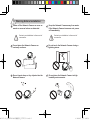
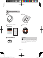
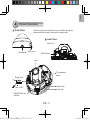
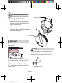
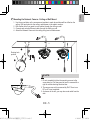
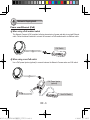
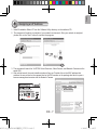
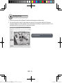
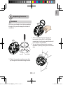
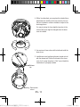
Warning Before Installation
Power off the Network Camera as soon as
smoke or unusual odors are detected.
Contact your distributor in the event of
occurrence.
Keep the Network Camera away from water.
If the Network Camera becomes wet, power
off immediately.
Contact your distributor in the event of
occurrence.
Do not place the Network Camera on
unsteady surfaces.
Do not touch the Network Camera during a
lightning storm.
Do not insert sharp or tiny objects into the
Network Camera.
Do not place the Network Camera in high
humidity environments.
625017000G_QIG,FD8136(15國語言)_VVTK,V1.0.indd 1
2012/3/27 上午 09:18:53
1
Package Contents
FD8136
Screws
Quick Installation Guide /
Warranty Card
Software CD
5 0 0 0 2 47 0 1 G
Focus Adjustment Tool
625017000G_QIG,FD8136(15國語言)_VVTK,V1.0.indd 2
NOTE:
All cables are user-supplied. Use a CAT5 standard UTP
or better quality cable. In order to pass the Ethernet cable
through the routing path, the maximum cable diameter
allowed is 5.2mm.
EN - 2
2012/3/27 上午 09:18:54
English
2
Physical Description
Outer View
Leave the slide cover in place if you route cables through the
bottom and then through a hole on the ceiling or wall.
Inner View
Side View
Release tab
Slide cover
RJ-45 Socket
Lens
Tilt adjustment
screw
Digital input
DI+ DI-
Reset button
Max. is 40V.
Screw slot
MicroSD/SDHC
card slot
625017000G_QIG,FD8136(15國語言)_VVTK,V1.0.indd 3
EN - 3
2012/3/27 上午 09:18:55
3
Hardware Installation
Slide cover
Semi-circular
cut-out
Removing the Dome Cover
1. Use one hand to hold the camera bottom
and another hand to hold the dome cover.
Press the release button.
2. Remove the dome cover.
3. Remove the slide cover if you want to route
cables from the side of camera instead of a
hole on the ceiling or wall.
1
2
Release tab
IMPORTANT:
1. Record the MAC address before installing
the camera.
NOTE:
2
0002D10766AD
It is recommended to use an Ethernet cable that
comes without the strain relief boot. You can
remove the boot if your cable comes with one.
2. You can check the model name suffix for the
type of lens mounted on your camera. The
applicable lens can be:
F2: 2.5mm; F3: 3.6mm; F6: 6mm; F8: 8mm;
F12: 12mm. The shorter the focal length, the
wider the view.
625017000G_QIG,FD8136(15國語言)_VVTK,V1.0.indd 4
Strain relief boot
EN - 4
2012/3/27 上午 09:18:55
English
Mounting the Network Camera - Ceiling or Wall Mount
1. Use the curved slots on the camera as a template to mark where holes will be drilled on the
ceiling. Drill two holes into the ceiling; and hammer in the plastic anchors.
2. Drill another hole if you want to route cables through the ceiling or wall.
3. Connect and route an Ethernet cable through the ceililng or wall.
4. Attach the Network Camera to the ceiling using two included screws.
2
Routing hole
position
3
4
1
625017000G_QIG,FD8136(15國語言)_VVTK,V1.0.indd 5
NOTE:
1. Do not completely tighten the mounting screws in the
screw slots yet. You may need to turn the camera left or
right for a best shooting direction later.
2. The camera can only be powered by PoE. There is no
DC or AC input connector.
3. As shown on the left, you may also route cable from the
side.
EN - 5
2012/3/27 上午 09:18:56
4
Network Deployment
Power over Ethernet (PoE)
When using a PoE-enabled switch
This Network Camera is PoE-compliant, allowing transmission of power and data via a single Ethernet
cable. Follow the below illustration to connect the camera to a PoE-enabled switch via Ethernet cable.
PoE Switch
POWER
COLLISION
1
2
3
4
5
LINK
RECEIVE
PARTITION
When using a non-PoE switch
Use a PoE power injector (optional) to connect between the Network Camera and a non-PoE switch.
625017000G_QIG,FD8136(15國語言)_VVTK,V1.0.indd 6
PoE Power Injector
(optional)
POWER
COLLISION
1
2
3
4
5
LINK
RECEIVE
PARTITION
Non-PoE Switch
EN - 6
2012/3/27 上午 09:18:57
English
5
Assigning an IP Address
1. Install “Installation Wizard 2” from the Software Utility directory on the software CD.
2. The program will conduct an analysis of your network environment. After your network is analyzed,
please click on the “Next” button to continue the program.
IW2
Installation
Wizard 2
3. The program will search for VIVOTEK Video Receivers, Video Servers, and Network Cameras on the
same LAN.
4. After a brief search, the main installer window will pop up. Double-click on the MAC address that
matches the one printed on the camera label or the S/N number on the package box label to open a
browser management session with the Network Camera.
172.16.7.13
PZ71X2
FD8136
2
0002D10766AD
625017000G_QIG,FD8136(15國語言)_VVTK,V1.0.indd 7
0002D10766AD
EN - 7
2012/3/27 上午 09:18:57
6
Ready to Use
1. A browser session with the Network Camera should prompt as shown below.
2. You should be able to see live video from your camera. You may also install the 32-channel
recording software from the software CD in a deployment consisting of multiple cameras. For its
installation details, please refer to its related documents.
625017000G_QIG,FD8136(15國語言)_VVTK,V1.0.indd 8
For further setup, please refer to the user's manual
on the software CD.
EN - 8
2012/3/27 上午 09:18:58
English
7
Adjusting the Lens
WARNING
Do not use your hands to tune the lens module's
tilt angle. Doing so will damage the delicate tilt
mechanism.
1. There is a tilt adjustment screw near the
lens module. Use a #0, #1, or #2 Phillips
screwdriver to turn the screw and the lens will
move upwards or downwards.
2. You may also tune the camera's horizontal
orientation by turning it along its curved screw
slots.
25°
Lens DOWN
°
25
Lens UP
3. Tighten the camera's mounting screws after
you change the horizontal shooting direction.
625017000G_QIG,FD8136(15國語言)_VVTK,V1.0.indd 9
57°
EN - 9
2012/3/27 上午 09:18:59
625017000G_QIG,FD8136(15國語言)_VVTK,V1.0.indd 10
4. With a live video feed, you can place the included focus
adjustment tool carefully on the lens, and use it to turn
the lens clockwise or counter-clockwise to adjust to the
best image focus.
You may try tuning the focus slightly closer due to the
concern that focus might be changed when the dome
cover is installed.
5. Use a piece of clean cotton cloth to hold and install the
dome cover.
6. Install dome cover by aligning the semi-circular cut-out
with the release tab. Press on both ends of the dome
cover for it to snap into place. A "click" sound should be
heard when it is properly installed.
Release
tab
Semi-circular
cut-out
EN - 10
2012/3/27 上午 09:19:00


![Cover [PZ81x1,x1W].ai](http://vs1.manualzilla.com/store/data/006040535_1-42ed705d921c196e7271c308c8c31f51-150x150.png)