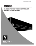
1
Managed MediaConverterChassisSystem
Preface
The Managed Media Converter Chassis System supports the Media Converter Chassis to
monitor the each Media Converter ( CO ) or Chassis Manager status and to configure
advanced function of the Managed Converter Chassis. Through Out-band management
via Web Browser utility to monitor/configure the Managed Media Converter Chassis
System.
This manual describes how to configure all Media Converter ( CO ), Chassis Manager and
each Managed Converter Chassis, which features eight slots of Meida Converters ( CO or
Chassis Manager ) in one Managed Converter Chassis, as well as the Remote side /
Terminal Media Converter ( CPE ).
The system allow to have 4 Managed Converter Chassis on one Managed System by
using IN/OUT Port for stacking, all you require to do is simply slide in one Chassis Manager
to any of Managed Converter Chassis in order to manage the system..
To get the most out of this manual, you should have an understanding of networking
concepts such as bridging, IEEE 802.3 10Base-T Ethernet, IEEE802.3u 100Base-TX/FX
Fast Ethernet and local area networks (LANs).
For more information about these topics, please refer to the Appendix.
1 User Manual
Managed MediaConverterChassisSystem
Table of Contents
Preface
Table of Contents
Chapter Overview
1
2
3
Technical Specifications
3
System Configuration
3
Application and Connector Pinouts
3
Technical Specification
4
Chassis Manager
4
Media Converter ( MC ) as CO side
6
Media Converter ( Terminal ) as CPE side
8
8 Slot Managed Converter Chassis
9
System Configuration
11
Connecting to Power
11
Chassis Stacking
11
Web-Based Browser Interface
12
Logging on to The Managed Media Converter Chassis System12
Main Menu
12
1. System Change
13
2. IP Configuration
14
3. Chassis
14
4. Monitor
22
5. SNMP Configuration
26
6. Alarm
27
7. Save
29
8. Default
31
9. Update Firmware
32
Appendix A - Connector Pinouts
2 User Manual
33
Managed MediaConverterChassisSystem
Chapter Overview
Technical Specifications
This chapter contains the following models:
1.Chassis Manager
2.Media Converter ( MC ) as CO side
3.Media Converter ( Terminal ) as CPE side
4.8 Slot Managed Converter Chassis
System Configuration
This chapter provides network managers and system administrators with information about
how to configure the Managed Media Converter Chassis System via the Web Browser.
The reader of this document should be knowledgeable about network devices, device
configuration, network management, and Internet browers. The user is assumed to be
network administrator or manager with an understanding of network operations.
Application and Connector Pinouts
See Appendix A for more information.
3 User Manual
Managed MediaConverterChassisSystem
Technical Specification
Chassis Manager
Key Features
z
One-channel media conversion between 10/100Base-TX and 100Base-FX.
z
Support AUTO-Negotiation and AUTO-MDIX for 10/100Base-TX Port.
z
Fiber media allows:
Multi-mode fiber using SC, ST, VF-45, MT-RJ, or LC connector
Single-mode fiber using SC or ST connector
WDM single-fiber ( bi-direction ) transceiver: Single-mode WDM fiber Using SC
connector.
A type: WDM single-fiber ( bi-direction ) transceiver transmits with 1310nm
wavelength and receives with 1550nm wavelength.
B type: WDM single-fiber ( bi-direction ) transceiver transmits with 1550nm
wavelength and receives with 1310nm wavelength.
z
Built-in 128K bits RAM for data buffer.
z
Built-in CPU with 2M Bytes Flash & 8M Bytes SDRAM
z
Status LEDs.
z
Used with a Managed Chassis.
z
Hot-swappable when used with a managed chassis.
z
System Change – Device Name, New Password, Old Password, Version, MAC
address
z
IP Configuration – DHCP, IP address, Netmask, Default Gateway
z
Chassis Hardware Monitor – Temperature, Supply Voltage Value, Fan Status,
z
CO MC Status – Operation Status, Link Status, Receive Count, Drop Count,
Active MC, Uptime
Collision Count
z
CO MC Control – Forwarding Mode, Remote Control, Link Fault Pass Through,
Port Mode, Flow Control, MDIX, Output Rate, Input Rate, Informing Way for
Receiving Off
4 User Manual
Managed MediaConverterChassisSystem
z
CPE MC Auto Report
z
CPE MC Status – Status of power, Status of receiving optical power, Terminal link
status, MC status, Informing way for optical receiving power off, Status of loopback
test, Notification of link status for the terminal, Terminal link speed, Duplex for the
terminal, Capability of auto-negotiation for the terminal, Number of interface in
Terminal
z
CPE MC Control - Forwarding Mode, Remote Control, Link Fault Pass Through,
Port Mode, Flow Control, MDIX, Output Rate, Input Rate, Informing Way for
Receiving Off
z
Loopback Test
z
MC Hardware Monitor – Temperature, Supply Voltage
z
SNMP Configuration - System Contact, System Location, Get Community, Set
Community
z
Alarm – Alarm Configuration, Hardware Alarm Configuration, Alarm Mail-Trap,
Alarm SNMP-Trap
z
TFTP Client for Software Upgrade
z
Telnet, SNMP V1 & V2, Web Browser, and TFTP Management
z
Enterprise MIB
z
Used as with a Managed Chassis.
z
Hot-swappable in any Slot when used with a managed chassis.
z
Able to Manage up to 32 CPE Converters.
Technical Specification
LED: Per Unit –
Per Port –
PW/FA (Power, Failure Alarm)
Console: Activity (Left LED), Full-duplex/Collision (Right LED)
10/100TX: LK/AT (Link/Activity), FD/CL (Full-duplex/Collision)
100FX: LK/AT (Link/Activity)
Ethernet Standards: IEEE 802.3 10Base-T, IEEE 802.3u 100Base-TX, 100Base-FX
Cable: 10Base-T2-pair UTP Cat. 3, 4, 5, up to 100m (328ft)
5 User Manual
Managed MediaConverterChassisSystem
100Base-TX 2-pair UTP Cat. 5, up to 100m (328ft)
100Base-FX 50 or 62.5/125um Multi-mode fiber optic cable
9 or 10/125um Single-mode fiber optic cable
Switching Method: Store-and -Forward
Forwarding Rate: 14,880pps for 10Mbps; 148,810pps for 100Mbps
Power Consumption:
4.2W Max.
Physical Specification
Power: 0.35A @ 12VDC Power Supply
Operating Temperature:0℃ ~ 45℃ (32℉ ~ 113℉)
Storage Temperature: -10℃ ~ 70℃ (14℉ ~ 158℉)
Humidity: 5 ~ 95%, non-condensing
Emission & Compliance: CE Mark Class A, FCC Part 15 Class A
Dimensions:80mm (W) x 124mm (D) x 20mm (H)
(3.15” (W) x 4.88” (D) x 0.79” (H))
Net Weight: 160g (0.35lb.)
Media Converter ( MC ) as CO side
Key Features
z One-channel media conversion between 10/100Base-TX and 100Base-FX.
z Support AUTO-Negotiation and AUTO-MDIX for 10/100Base-TX Port.
z Fiber media allows:
Multi-mode fiber using SC, ST, VF-45, MT-RJ, or LC connector
Single-mode fiber using SC or ST connector
WDM single-fiber ( bi-direction ) transceiver: Single-mode WDM fiber Using SC
connector.
z Built in 128K bits RAM for data buffer.
6 User Manual
Managed MediaConverterChassisSystem
z Status LEDs.
z Used with a Managed Chassis.
z Hot-swappable when used with a managed chassis.
Technical Specification
LED: Per Unit –
Per Port –
PW/FA (Power, Failure Alarm)
10/100TX: LK/AT (Link/Activity), FD/CL (Full-duplex/Collision)
100FX: LK/AT (Link/Activity)
Ethernet Standards: IEEE 802.3 10Base-T, IEEE 802.3u 100Base-TX, 100Base-FX
Cable: 10Base-T2-pair UTP Cat. 3, 4, 5, up to 100m (328ft)
100Base-TX 2-pair UTP Cat. 5, up to 100m (328ft)
100Base-FX 50 or 62.5/125um Multi-mode fiber optic cable
9 or 10/125um Single-mode fiber optic cable
Switching Method: Store-and -Forward
Forwarding Rate: 14,880pps for 10Mbps; 148,810pps for 100Mbps
Power Consumption:
3W Max.
Physical Specification
Power: 0.25A @ 12VDC Power Supply
Operating Temperature:0℃ ~ 45℃ (32℉ ~ 113℉)
Storage Temperature: -10℃ ~ 70℃ (14℉ ~ 158℉)
Humidity: 5 ~ 95%, non-condensing
Emission & Compliance: CE Mark Class A, FCC Part 15 Class A
Dimensions:80mm (W) x 124mm (D) x 20mm (H)
(3.15” (W) x 4.88” (D) x 0.79” (H))
Net Weight: 160g (0.35lb.)
7 User Manual
Managed MediaConverterChassisSystem
Media Converter ( Terminal ) as CPE side
Key Features
zOne-channel media conversion between 10/100Base-TX and 100Base-FX.
zSupport AUTO-Negotiation and AUTO-MDIX for 10/100Base-TX Port.
zFiber media allows:
Multi-mode fiber using SC, ST, VF-45, MT-RJ, or LC connector
Single-mode fiber using SC or ST connector
WDM single-fiber ( bi-direction ) transceiver: Single-mode WDM fiber Using SC
connector.
zBuilt in 128K bits RAM for data buffer.
zStatus LEDs.
zWall-mountable.
zExternal Power Adapter (0.25A @ 12VDC)
Technical Specification
LED: Per Unit –
Per Port –
PW/FA (Power, Failure Alarm)
10/100TX: LK/AT (Link/Activity), FD/CL (Full-duplex/Collision)
100FX: LK/AT (Link/Activity)
Ethernet Standards: IEEE 802.3 10Base-T, IEEE 802.3u 100Base-TX, 100Base-FX
Cable: 10Base-T2-pair UTP Cat. 3, 4, 5, up to 100m (328ft)
100Base-TX 2-pair UTP Cat. 5, up to 100m (328ft)
100Base-FX 50 or 62.5/125um Multi-mode fiber optic cable
9 or 10/125um Single-mode fiber optic cable
Switching Method: Store-and -Forward
Forwarding Rate: 14,880pps for 10Mbps; 148,810pps for 100Mbps
Power Consumption:
8 User Manual
3W Max.
Managed MediaConverterChassisSystem
Physical Specification
Power: 0.25A @ 12VDC Power Supply
Operating Temperature:0℃ ~ 45℃ (32℉ ~ 113℉)
Storage Temperature: -10℃ ~ 70℃ (14℉ ~ 158℉)
Humidity: 5 ~ 95%, non-condensing
Emission & Compliance: CE Mark Class A, FCC Part 15 Class A
Dimensions:80mm (W) x 124mm (D) x 20mm (H)
(3.15” (W) x 4.88” (D) x 0.79” (H))
Net Weight: 160g (0.35lb.)
8 Slot Managed Converter Chassis
Key Features
zEach Chassis Houses 8 Slots (Converters)
zSlim 1U Height 19” Design to Save Space
zStackable up to Four Chassis (up to 32 Converters)
zHot Swappable
zSupports Power Redundancy
Technical Specifications
LED: PWR1 – For AC Power status
PWR2 – For DC Power status
Fan 1 / Fan 2 – For Fan status.
STK IN / STK OUT – For stack port status
Stacking Port: RJ-45
Stacking Cable:
Cat 5 with Max Length of 1 Meter
Terminal Block: For Redundant Power (2.67A @ 12VDC)
9 User Manual
Managed MediaConverterChassisSystem
Environmental Specifications
Power: AC Input: 100-240V
DC Input: 2.67A @ 12VDC
Operating Temperature:0℃ ~ 45℃ (32℉ ~ 113℉)
Storage Temperature: -10℃ ~ 70℃ (14℉ ~ 158℉)
Humidity: 5 ~ 95%, non-condensing
Emission & Compliance: CE Mark Class A, FCC Part 15 Class A
Dimensions:440mm (W) x 235mm (D) x 44mm (H)
(17.32” (W) x 9.25” (D) x 1.73” (H))
Net Weight: 3Kg (6.6lbs.)
10 User Manual
Managed MediaConverterChassisSystem
System Configuration
Connecting to Power
The chassis system is equipped with two power connectors. When the chassis is
connecting with two powers, you can have the redundant function.
AC power connector DC power connector
AC 100V ~ 240V
2.67A @ 12VDC
Chassis Stacking
The Stacking function allows up to four chassis to be interconnected via their Stacking ports.
This forms a four chassis stack that can then be managed and configured as thought the
entire stack were a single chassis manager. The chassis stack is then accessed through a
single IP address.
The stacking ports are marked IN and OUT. The RJ45 compliant cable must be connected
from an IN port on one Switch to an OUT port on the next Switch in the stack. The last two
Switches (at the top and bottom of the stack) must also be connected from the IN port on
one Switch to the OUT port on the other Switch. In this way, a loop is made such that all of
the Switches in the Switch stack have the IN stacking port connected to another Switch’s
OUT stacking port.
< NOTE > : chassis number is configured using the front panel switch.
11 User Manual
Managed MediaConverterChassisSystem
Web-Based Browser Interface
The Managed Media Converter Chassis System is accessible using a Web browser ( IE
explorer, Netscape Communication, etc. ) to open up the Managed Converter Chassis
monitering System.
Logging on to The Managed Media Converter Chassis System
The default IP Address for the System is ‘192.168.1.10 ’, and there is no need to type in both
‘ Login name ‘ and ‘ password ‘ as default, just simply press ‘ OK ‘ to start the Main Screen.
Main Menu
12 User Manual
Managed MediaConverterChassisSystem
1. System Change
There are five items in the System Change menu : ‘ Device Name ‘, ‘ New Password ‘, ‘ Old
Password ‘, ‘ Version ‘ and ‘ Mac Address ‘.
1.1. Device Name :
This section is to set your own ‘ Device Name ‘.
1.2. New Password :
This section is to set your own ‘ New Password ‘.
1.3. Old Password :
This section is to verify the old password you set before.
1.4. Version :
This is an indication of the Software version for reference.
1.5. Mac Address :
This is the information of Mac Address of your Device.
< NOTE > : After configuring the Device, need to press the ‘ Apply ‘ botton to save the
setting.
13 User Manual
Managed MediaConverterChassisSystem
2. IP Configuration
There are 4 items in the IP Configuration : ‘ DHCP ‘, ‘ IP Address ‘, ‘ Netmask ‘ and ‘ Default
Gateway ‘.
2.1. DHCP :
To set the DHCP ‘ Enable ‘ or ‘ Disable ‘.
2.2. IP Address :
To allocate an IP Address for the Managed Converter Chassis, the default IP is
‘ 192.168.1.10 ‘.
2.3. Netmask :
To set the Netmask, the default is ‘ 255.255.255.0 ‘.
2.4. Default Gateway :
To set the default Gateway address is ‘ 192.168.1.254 ‘.
< NOTE > : After configuration set, need to press the ‘ Apply ‘ button to save the setting.
3. Chassis
3.1. Chassis Hardware Monitor
This section divide to 4 different Managed Converter Chassis with No. on each Chassis unit.
14 User Manual
Managed MediaConverterChassisSystem
Chassis => Chassis # 0~3 => Chassis H/W Monitor
This section you can see the Chassis # 0~3 Hardware Monitor :
Temperature.
Supply Voltage Value ( 12 Volts ) : Suggest the normal condition 12 Volts ( +/- 10% ).
Fan Status : There are 2 Fans in Chassis ( Status : ‘ On ‘ or ‘ Off ‘ ).
Active MC : There are 8 slots for Media Converter or Chassis Manager ( Status : ‘ Active ‘ or
‘ Inactive ‘ ).
Uptime.
< NOTE > : This menu can also be read simply point the Left hand side of ‘ Managed
Converter Chassis ‘ on the top graphic of Chassis # 0~3 where the ‘ Chassis Hardware
Switch ‘ is.
3.2. CO MC Status
This section you can see the Media Converter # 1~8 inside of Chassis # 0~3
Chassis => Chassis # 0~3 => MC # 1~8 => CO MC Status
15 User Manual
Managed MediaConverterChassisSystem
Operation Status : ‘ Normal ‘ or ‘ Local loop test ‘ or ‘ Far end fault ‘ or ‘ Hardware fault ‘ or
‘ Software fault ‘.
Media Port 1 ( Type : Current Model ) : ‘ Link Status ‘, ‘ Receive Count ‘, ‘ Drop Count ‘, and
‘ Collision Count ‘.
Media Port2 ( Type : Current Model ) : ‘ Link Status ‘, ‘ Receive Count ‘, ‘ Drop Count ‘, and
‘ Collision Count ‘.
< NOTE > : If the Status needs to be calculated from fresh, please press the ’ Reset ‘ botton
to restart the counting.
< NOTE > : This menu can also be read simply point the Left hand side of ‘ Managed
Converter Chassis ‘ on the top graphic of Chassis # 0 where the ‘ Chassis Hardware Switch
is.
3.3. CO MC Control
Chassis => Chassis # 0~3 => MC # 1~8 => CO MC Control
16 User Manual
Managed MediaConverterChassisSystem
MC Options :
Forwarding Mode : ‘ Store-Forward ‘ or ‘ Cut–Through ‘ or ‘ Repeater ‘ or ‘ Auto-Change ‘.
Remote Control : ‘ Disable ‘ or ‘ Enable ‘.
Link Fault Pass Through : ‘ Disable ‘ or ‘ Enable ‘.
Media Port1 ( Type : Current Model ) :
Port Mode : ‘ Auto ‘ or ‘ 10HD ‘ or ‘ 10FD ‘ or ‘ 100HD ‘ or ‘ 100FD ‘.
Flow Control : ‘ Disable ‘ or ‘ Enable ‘.
MDIX : ‘ Disable ‘ or ‘ Enable ‘.
Output Rate : ‘ Full ‘ or ‘ 25% ‘ or ‘ 50% ‘ or ‘ 75% ‘.
Input Rate : ‘ Full ‘ or ‘ 25% ‘ or ‘ 50% ‘ or ‘ 75% ‘.
Media Port2 ( Type : Current Model ) :
Port Mode : ‘ 100HD ‘ or ‘ 100FD ‘.
Flow Control : ‘ Disable ‘ or ‘ Enable ‘.
Informing Way for Receiving Off : ‘ Maintenance Frame ‘ or ‘ Far-End-Fault Pattern ‘.
< NOTE > : After configuration set, need to press the ‘ Apply ‘ and ‘ Save ‘ buttons to save
the setting.
17 User Manual
Managed MediaConverterChassisSystem
3.4. CPE MC AutoReport
Chassis => Chassis # 0~3 => MC # 1~8 => CPE MC AutoReport
Status of Loopback test : ‘ Not Test ‘ or ‘ Test ‘.
Option B : ‘ Support ‘ or ‘ Not Support ‘.
< Note > : If the Option B is support by Terminal side, which can inform speed, duplex,
and auto-negotiation in terminal, our default setting is ‘ Support ‘.
TP port auto-negotiation : ‘ Enable ‘ or ‘ Disable ‘.
TP port speed selection : ‘ 100M ‘ or ‘ 10M ‘.
TP port duplex mode selection : ‘ Full ‘ or ‘ Half ‘.
TP port flow control selection : ‘ Enable ‘ or ‘ Disable ‘.
TP port link : ‘ Link Up ‘ or ‘ Link Down ‘.
Fiber port flow control/backpressure : ‘ Enable ‘ or ‘ Disable ‘.
Fiber port duplex mode : ‘ Full ‘ or ‘ Half ‘.
Fiber port signal detect : ‘ On ‘ or ‘ Off ‘.
MC power status : ‘ Normal ‘ or ‘ Fault ‘.
MC status : ‘ Normal ‘ or ‘ Fault ‘.
18 User Manual
Managed MediaConverterChassisSystem
Informing way for optical receiving power off : ‘ Far-End-Fault Pattern ‘ or ‘ Maintenance
Frame ‘.
MC support multi-port UTP : ‘ 1 ‘ or ‘ More Than 1 ‘.
Link Fault Pass Through : ‘ Disable ‘ or ‘ Enable ‘.
3.5. CPE MC Status
Chassis => Chassis # 0~3 => MC # 1~8 => CPE MC Status
Status of power : ‘‘ Power On ‘ or ‘ Power Off ‘.
Status of receiving optical power : ‘ Normal ‘ or ‘ Fault ‘.
Terminal link status : ‘ Link Up ‘ or ‘ Link Down ‘.
MC status : ‘ Normal ‘ or ‘ Fault ‘.
Informing way for optical receiving power off : ‘ Far-End-Fault Pattern ‘ or ‘ Maintenance
Frame ‘.
Status of loopback test : ‘ Normal ‘ or ‘ Fault ‘.
Notification of link status for the terminal : ‘ Support ‘ or ‘ Not Support ‘.
Terminal link speed : ‘ 100M ‘ or ‘ 10M ‘.
Duplex for the terminal : ‘ Full ‘ or ‘ Half ‘.
19 User Manual
Managed MediaConverterChassisSystem
Capability of auto-negotiation for the terminal : ‘ Enable ‘ or ‘ Disable ‘.
Number of interface in terminal : ‘ 1 ‘ or ‘ More Than 1 ‘.
< NOTE > : If you wish to get the most recent remote status, please press the ‘ Apply ‘ button
for the status.
3.6. CPE MC Control
Chassis => Chassis # 0~3 => MC # 1~8 => CPE MC Control
MC Options :
Forwarding Mode : ‘ Store-Forward ‘ or ‘ Cut–Through ‘ or ‘ Repeater ‘ or ‘ Auto-Change ‘.
Remote Control : ‘ Disable ‘ or ‘ Enable ‘.
Link Fault Pass Through : ‘ Disable ‘ or ‘ Enable ‘.
Media Port 1 ( Type : Current Model ) :
Port Mode : ‘ Auto ‘ or ‘ 10HD ‘ or ‘ 10FD ‘ or ‘ 100HD ‘ or ‘ 100FD ‘.
Flow Control : ‘ Disable ‘ or ‘ Enable ‘.
MDIX : ‘ Disable ‘ or ‘ Enable ‘.
Output Rate : ‘ Full ‘ or ‘ 25% ‘ or ‘ 50% ‘ or ‘ 75% ‘.
Input Rate : ‘ Full ‘ or ‘ 25% ‘ or ‘ 50% ‘ or ‘ 75% ‘.
20 User Manual
Managed MediaConverterChassisSystem
Media Port2 ( Type : Current Model ) :
Port Mode : ‘ 100HD ‘ or ‘ 100FD ‘.
Flow Control : ‘ Disable ‘ or ‘ Enable ‘.
Informing Way for Receiving Off : ‘ Far-End-Fault Patten ‘ or ‘ Maintenance Frame ‘.
< NOTE > : After configuration set, need to press the ‘ Apply ‘ button to save the setting.
3.7. Loop-back Test
Chassis => Chassis # 0~3 => MC # 1~8 => Loop-back Test
Status : ‘ Final ‘ or ‘ Error ‘.
Result : ‘ OK ‘ or Message for error.
< NOTE > : If you wish to retest for Loopback Test again, please press the ‘ Apply ‘ botton for
the most update status.
3.8. MC Hardware Monitor
Chassis => Chassis # 0~3 => MC # 1~8 => MC H/W Monitor
21 User Manual
Managed MediaConverterChassisSystem
Temperature : + 45 C
Supply Voltage ( 2.5 Volts )
Supply Voltage ( 3.3 Volts )
Supply voltage ( 12 Volts )
< NOTE > : Under the normal condition, suggest the tolerance for all Supply Voltage should
not exceed +/- 10%.
4. Monitor
4.1. Total CO MC Status
Monitor => Chassis # 0 ~3 => Total CO MC Status
This section divide to 3 different Managed Converter Chassis with No. on each Chassis unit.
22 User Manual
Managed MediaConverterChassisSystem
This section you can see the MC Status for all Media Converter installed in the Chassis .
4.2. Total CPE MC AutoReport
Monitor => Chassis # 0~3 => Total CPE MC AutoReport
This section you can see the Terminal MC Auto Report for all Media Converter installed in
the Chassis.
23 User Manual
Managed MediaConverterChassisSystem
4.3. Total CPE MC Status
Monitor => Chassis # 0~3 => Total CPE MC Status
This section you can see the Terminal MC Status for all Media Converter installed in the
Chassis .
4.4. Total Loopback Test
Monitor => Chassis # 0~3=> Total Loopback Test
24 User Manual
Managed MediaConverterChassisSystem
This section you can see the Loopback Test Status for all Media Converter installed in the
Chassis .
4.5. Total MC Hardware Status
Monitor => Chassis # 0~3=> Total MC Hardware Status
This section you can see the MC Hardware Status for all Media Converter installed in the
Chassis.
25 User Manual
Managed MediaConverterChassisSystem
4.6. Chassis Monitor
This section you can monitor all the 0~3 Managed Converter Chassis status.
5. SNMP Configuration
26 User Manual
Managed MediaConverterChassisSystem
System Contact : Contact information for the system administrator responsible for managing
system.
System Location : Description of where your system is physically located.
Get Community : public / private
Set Community : public / private
6. Alarm
6.1. Alarm Configuration
Allows a network administrator to define alarm events.
6.2. H/W Alarm Configuration
27 User Manual
Managed MediaConverterChassisSystem
Low Power Limit (%) : 0 ~ 100 %
High Temperature Limit (C) : Suggest set on 45 ℃
Fan Operation Time Limit (Hours) : 1000 Hours or more
6.3. Alarm Mail – Trap
28 User Manual
Managed MediaConverterChassisSystem
If you check the « enable » Alarm by SMTP, system will send alarm information to the
configured email address through the configured mail server.
6.4. Alarm SNMP – Trap
SNMP enables network administrators to manage network performance, find and solve
network problems. When SNMP-Trap events are « ON », the device can send out trap
messages automatically to the trap manager if configured.
7. Save
7.1. Configuration of Chassis Manager
29 User Manual
Managed MediaConverterChassisSystem
If press OK for the ‘ Are you sure ? ‘ column, all changed configuration for Chassis Manager
will be saved. And Cancel will be no save.
7.2. Configuration of all MC
If press the save for configuration of all MC, all previous changes of configuration will be
starting to save until it shows ‘ Done ‘.
< NOTE > : Note the N/A indicate ‘ Not Applicable ‘.
30 User Manual
Managed MediaConverterChassisSystem
8. Default
8.1. Configuration of Chassis Manager
If press OK for the ‘ Are you sure ? ‘ column, all configuration for Chassis Manager will be
reset to factory default. And all configuration for Chassis Manager will not be reset to factory
default if Cancel will be pressed.
8.2. Configuration of all MC
31 User Manual
Managed MediaConverterChassisSystem
If press the default for configuration of all MC, all configuration will be reset to factory default
until it shows ‘ Done ‘.
< NOTE > : Note the N/A indicate ‘ Not Applicable ‘.
9. Update Firmware
You can update the firmware of your system. Normally, this is done when a new version of
firmware is released.
32 User Manual
Managed MediaConverterChassisSystem
Appendix A - Connector Pinouts
The following table lists the pinout of the Ethernet Switch’ s 10/100Base-TX ports.
For 10/100Base
Pin 1 / 3
Trans / Receive
Data +
For 10/100Base
Pin 2 / 6
Trans / Receive
Data -
100BASE-FX: 100Mbp Ethernet implementation over fiber.
100BASE-TX: 100Mbps Ethernet implementation over Category 5 and Type 1 Twisted
Pair cabling.
10BASE-T: The IEEE 802.3 specification for Ethernet over Unshielded Twisted Pair (UTP)
cabling.
auto-negotiation: A feature on a port that allows it to advertise its capabilities for speed,
duplex, and flow control. When connected to an end station that also supports
auto-negotiation, the link can self detect its optimum operating setup.
stack: A group of network devices that are integrated to form a single logical device.
TFTP: Trivial File Transfer Protocol. Allows you to transfer files (such as software upgrades)
from a remote device using your switch’s local management capabilities.
33 User Manual