1
ISSN(Online): 2320-9801
ISSN (Print): 2320-9798
International Journal of Innovative Research in Computer
and Communication Engineering
(An ISO 3297: 2007 Certified Organization)
Vol. 2, Issue 4, April 2014
A Zigbee Based Inter-Processor Communication
Architecture for the Management of Bedchambers
for the Physically Challenged
Tinotenda Zwavashe
M Tech Student, Department of ECE, Jawaharlal Nehru Technological University Hyderabad, India.
ABSTRACT: The paper illustrates designing of a system which comes to the aid of the physically challenged people
for example those who are blind, those with stroke, hands or legs paralysis and all forms of physical disabilities. Its use
can also extend to the young and very old members of a family. This is an inter-processor communication system
whereby the parameters and gadgets of a bedroom can be monitored and controlled from another room. The parameter
is the room temperature while gadgets are the lights, fan and alarm. Status of any of these can be checked using the
QUERY feature. The system also includes a PC which can be connected by the paralysed member, depending on the
level of paralysis, so that he/she also can be able to control these features from his/her bed. The PC is equipped with a
user friendly graphical user interface designed using C# while at the other end control and monitoring is achieved using
switches, keypad and LCD display. Another interesting feature is that when there is some power cut the status of the
system is preserved by incorporating an EEPROM such that last status is reloaded on system start up. Processor to
processor communications is achieved using zigbee technology and the microcontrollers used are the PIC16F877A and
LPC2148.
KEYWORDS: Monitor and Control, zigbee, PIC16F877A, Query, LPC2148, LM35, 24LC04B EEPROM.
I. INTRODUCTION
The world is populated with a great number of people who have physical disabilities and in some cases who are on
home based care. One of the primary concerns is monitoring where they sleep especially if they occupy their own
room. Activities like switching on/off lights and fan, ringing an alarm to wake them up, responding to their emergence
button in case they need attention are of prime consideration in such cases. Thus by taking advantage of the
advancement in technology a system to deal with this control and monitoring is to be designed. The system aims to be
simple to use and very much portable. The author will give focus to two people. The first is the non-paralysed
(Advantaged) user in another room who shall be referred to as the ADV user and the paralysed (Disadvantaged)
member who shall be referred to as the DISADV user. These two are assumed to be using different rooms. Thus, the
system will consist of a PIC16F877A microcontroller connected in the ADV user’s room and the LPC2148 ARM based
microcontroller connected in the DISADV user’s room.
II. RELATED WORK
Wireless Monitoring and control has been implemented [1] but with the user interface resident on a PC. The master
node implements ARM based microcontroller and it is directly connected to PC using Ethernet and all the control and
monitoring is done on PC only. In [2] the coordinator has been implemented using ARM 9 while the sensor node uses
ARM 7 and the coordinator is directly attached to PC again with all monitoring being carried out on the same PC. One
directional wireless communication is implemented in [3]. The user interface consists of touch screen and not many
peripheral devices are included in the system. At the other end information send is available for display purposes only
and no return communication via the network is made.
III. PROPOSED SYSTEM
The proposed system aims to provide monitoring and control both on PC and on a user interface which implements
switches and LCD. Cost has been taken into account by implementing using low cost PIC microcontroller and also the
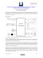
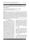
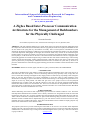
communication is bi-directional. Fig.1 and Fig.2 show the block diagrams of the system. Fig.1 shows the architecture
Copyright to IJIRCCE
www.ijircce.com
3866
ISSN(Online): 2320-9801
ISSN (Print): 2320-9798
International Journal of Innovative Research in Computer
and Communication Engineering
(An ISO 3297: 2007 Certified Organization)
Vol. 2, Issue 4, April 2014
of the DISADV user’s station while figure 2 shows the ADV user’s monitoring and control interface. Following this is
the hardware and software implementation descriptions of this system. The author has selected to use the LPC2148 on
the DISADV user’s side since it has 2 UARTs, UART0 and UART1. This will enable the connection of both the zigbee
module and PC at the same time.
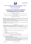
Fig. 1: The block architecture of the node to be monitored and controlled (The DISADV user node).
A. Hardware Description for LPC2148 station.
The hardware and software descriptions of the system will also illustrate how the system functions by analysis of how
each of the components contributes to system functionality. As can be seen from Fig.1, the following hardware
components are used to set up the monitored station:
1) LPC2148: This is the controller used to coordinate all activities happening at this node. It is a 32 bit ARM based
microcontroller. Its choice has mainly been influenced by the presence of two serial ports (UART0 and UART1) such
that one port communicates with the remote PIC microcontroller via zigbee and the other port communicates with PC’s
Graphical user interface. The microcontroller receives control instructions and query commands via both serial ports
and responds to give the status of the system.
2) LM35 Sensor: This is a temperature sensor which checks the room temperature. When system is in auto mode
temperature set points are defined (maximum and minimum temperature) and the fan can be switched ON and OFF
automatically if set points are exceeded. In manual mode the LM35 checks temperature value upon a request to know
the room temperature. Also in this mode the fan is switched ON/OFF by the users. The LM35 gives out an analogue
value, so the sensor is connected to the Analogue to Digital Conversion channel. The configuration of ADC module
and data capture is illustrated in Table 1.
Copyright to IJIRCCE
www.ijircce.com
3867
ISSN(Online): 2320-9801
ISSN (Print): 2320-9798
International Journal of Innovative Research in Computer
and Communication Engineering
(An ISO 3297: 2007 Certified Organization)
Vol. 2, Issue 4, April 2014
AD0CR = (AD0CR & 0xFFFF00FF) | 0x00000E00; /* bit 8 to 15 place value of 14 clock div value
to 4MHz */
AD0CR | = (1<<21);
/* set bit 21. Make AD converter functional*/
AD0CR | = (1<<1);
/* select channel AD0.1*/
AD0CR = (AD0CR &0xF8FFFFFF) |(1<<24);
/* start ADC now i.e. send 001 to 24-26 */
while (! ( AD0GDR & (0x80000000)));
/* wait for DONE bit to be SET to 1 to signify
end
of conversion */
Table 1: ADC module configuration and capture of digital data.
3)24LC04B EEPROM: The memory device stores the status of the system at any particular time. Any changes to the
system status is updated to this memory such that when there is some power failure then the system is reloaded to its
last known state upon restart.
4) Emergency Switch: This switch has been used as a provision that if the disadvantaged user has the physical
capability to press it then it can be used as a measure for him/her to gain attention from the advantaged user. A message
is carried to the ADV user and his attention is gained by use of a buzzer at the ADV user’s side.
5) Relays: These are switching devices and they are used to switch ON/OFF the fan and light which operate at high
voltages of around 230V. The relays are microcontroller controlled and they receive switching signals from the
LPC2148.
6) Buzzer: The buzzer functions as an alarm to wake up the DISADV user in the morning. It can be switched ON/OFF
remotely by the ADV user
B. Software Description for LPC2148 station.
1) Keil uVision: This is an Integrated Development Environment which is used for writing code for the LPC2148
microcontroller and compiling it. Several C files are created for the project and these are: The main file, UART0
control file, UART1 control file, file containing Interrupt Service Routines (ISRs) for UART0 and UART1 and LCD
manipulation file. Programming has been done using embedded C language.
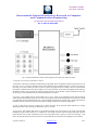
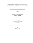
2) Visual Studio - C#: C# has been used to create the graphical user interface which is user friendly and simple. Code
has been written to control data transfer over the serial port including configuration of the baud rates for transmission.
The GUI is shown in Fig.3.
Copyright to IJIRCCE
www.ijircce.com
3868
ISSN(Online): 2320-9801
ISSN (Print): 2320-9798
International Journal of Innovative Research in Computer
and Communication Engineering
(An ISO 3297: 2007 Certified Organization)
Vol. 2, Issue 4, April 2014
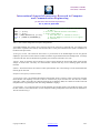
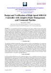
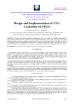
Fig. 2: The block architecture of the monitoring and Control node (The ADV user node).
C. Hardware Description for PIC16F877A station.
1) PIC16F877A:This microcontroller from Microchip is responsible for the coordination of all activities which occur at
this node. It is an 8 bit microcontroller and has been furnished with a 20MHz oscillator to increase the speed of
processing. It has 0ne USART port which is used to connect the zigbee transceiver module. The PIC microcontroller
sends query commands to the LPC2148 via zigbee so as to know the status of LPC2148 node gadgets and the status are
send back and they can be viewed on the LCD connected to the PIC microcontroller. Control commands are also send
the same way to switch ON/OFF devices and setting temperature set points.
2) Keypad: A 4x3 Keypad has been incorporated so as to type in values to set temperature values. Before entering
values the start button must be pressed so as to enter into key press mode. When the keypad enters into key press mode
it is signified by the red LED which turns ON. Upon pressing the OK button the entered value is send to the LPC2148.
Parameter selection switches are used to select between sending of maximum or minimum temperature.
3) LCD: A 20x4 LCD is used as a display unit. It shows the status of the LPC2148 station and also for viewing
different parameters while selecting the parameter to query or control.
4) Start button: This signifies that one has to put the microcontroller into a mode where it can accept user input data
through the keypad or push switches. It is connected as an interrupt to the PIC external interrupt port RB0. Thus the
microcontroller does not poll continuously for the user input interface but is drawn by means of an interrupt. A red
LED is lit when this button is pressed so that user can know that the microcontroller has responded to the command.
Copyright to IJIRCCE
www.ijircce.com
3869
ISSN(Online): 2320-9801
ISSN (Print): 2320-9798
International Journal of Innovative Research in Computer
and Communication Engineering
(An ISO 3297: 2007 Certified Organization)
Vol. 2, Issue 4, April 2014
5) Parameter selection switches: These up/down buttons are used to select the parameter which is to be queried or
controlled. These parameters have been incorporated together as an array of strings. When the desired parameter is
displayed then the OK button is pressed and the command is communicated to the remote station. Key presses are
signified by blue LED which flashes. These parameters are as follows:
unsignedchar *options[15]
=
{
"Switch Light ON",
"Switch Light OFF",
"Check Light State",
"Switch Fan ON",
"Switch Fan OFF",
"Check Fan State",
"Set Temperature",
"Check Temperature ",
"Switch Alarm ON",
"Switch Alarm OFF",
"Check Alarm State"
};
6) OK button: This is an acknowledgement key which is pressed when the desired parameter has been selected or when
the required value has been entered from the keypad. Upon pressing this key, data is transmitted over the serial port and
zigbee module to the remote station.
D. Software Description for PIC16F877A station.
1) MPLAB: This is the IDE which has been used to develop the code for the PIC16F877A microcontroller. The code
could have been developed in Assembly language or C language where MPASM or Hitech C Compiler could have
been used for each respectively. The author has developed the project using C language and Hitech C compiler. Five C
files were created which include keypad scan file, LCD display file, ISR file, main file and serial communications file.
E. Zigbee Modules: Zigbee communication protocol was achieved by the use of Digi International’s XBEE Series 2
modules. Configuration of the modules was done using X-CTU software for configuration of destination addresses and
other parameters. One module was configured as the COORDINATOR and the other one as the ROUTER, although
this cannot be noticed when the modules are functional. Xbee modules can be configured as coordinator, router or end
device and a PAN can have one coordinator and any number of routers and end devices. However only router and
coordinator can participate in routing data packets and also only coordinator or router can allow other devices to join
the network. These Xbee modules have an indoor range of about 40 meters and an outdoor range of about 120 meters.
IV. TESTING and RESULTS
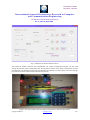
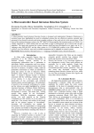
The system was built and tested and it performed according to expectations. Firstly the UART0 monitoring and control
section was tested where the LPC2148 system is connected to the PC and control and monitoring is done through the
C# graphical user interface. The layout of the GUI is shown in Fig.3. Commands were send and appropriate responses
were gathered. The system can easily detect the PORT number on the PC to which the system to be monitored is
connected. Baud rate values can also be selected from a drop down menu.
Copyright to IJIRCCE
www.ijircce.com
3870
ISSN(Online): 2320-9801
ISSN (Print): 2320-9798
International Journal of Innovative Research in Computer
and Communication Engineering
(An ISO 3297: 2007 Certified Organization)
Vol. 2, Issue 4, April 2014
Fig. 3: Graphical User Interface hosted on the PC.
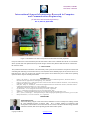
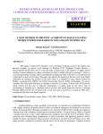
After testing the UART0 connection and communication, the UART1 communication interface was also tested
whereby the LPC2148 station communicates with the PIC16F877A station via the zigbee communication protocol.
Communication was established to perfection and commands were efficiently sent and responses received accordingly.
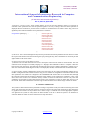
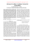
Fig.4 and 5 show the PIC station and LPC2148 station respectively.
Figure 4: The control station (ADV user) made up of PIC16F877A and associated controls.
Copyright to IJIRCCE
www.ijircce.com
3871
ISSN(Online): 2320-9801
ISSN (Print): 2320-9798
International Journal of Innovative Research in Computer
and Communication Engineering
(An ISO 3297: 2007 Certified Organization)
Vol. 2, Issue 4, April 2014
Figure 5: The DISADV user station composed of LPC2148 and associated peripherals.
Lastly all UARTS were connected whereby the LPC2148 station could receive commands from the PC or from the PIC
station. System status was updated effectively and all changes could be easily detected both from the PC and from the
PIC16F877A station.
V. CONCLUSION
The system has functioned to satisfaction. The functionality of the system can be extended to incorporate a master node
controlling and monitoring several nodes/rooms say at an institution where disabled people, the old, the sick who are on
home based care, and so on are kept. The response of the system can be enhanced by use of a Real Time Operating
System for faster response and task prioritization.
REFERENCES
1.
2.
3.
4
5.
6.
7.
8.
9.
Kumari, G. M., and Devi, V., “Real Time Automation and Monitoring System for Modernized Agriculture”, International Journal of
Review & Research in Applied Sciences and Engineering, Vol.3, March 2013.
Kolam, M., and Shree, S.R.B., “Zigbee Wireless Sensor Network for Better Interactive Industrial Automation”, IEEE, International q
Conference on Advanced Computing, 2011.
Reddy, M.R., Reddy, A.P., and Akhill, B., “Touchscreen and Zigbee based Wireless Communication Assistant”, International Journal of
Combined Research and Development, Vol.1, Issue.4, August 2013.
MaxStream Digi International., “Xbee Series 2 OEM RF Modules Product Manual”, 2007.
Digi International., “X-CTU Configuration and Test Utility User’s Guide”, August 2008.
Dogan, I., “Advanced PIC Microcontroller Projects in C from USB to Zigbee”, 2008.
Wilmshurst, T., “Designing Embedded Systems with PIC microcontrollers- Principles and Applications”, 2007.
Sloss, A., Symes, D., and Wright, C., “ARM System Developer’s Guide- Designing and Optimizing System Software”, pp.103-155, 2004.
Phillips Semiconductors., “LPC214x User Manual”, Vol.1, August 2005.
BIOGRAPHY
Tinotenda Zwavashe:
Attained his B.Eng. Degree in ECE from NUST, Zimbabwe in 2010. Currently he is studying towards
M. Tech Embedded Systems at JNTUH, India. . He is a Harare Institute of Technology staff
development research fellow. His research interests are in the area of Microcontroller Design, Wireless
and Sensor networks, Real Time Operating Systems and SCADA systems.
Copyright to IJIRCCE
www.ijircce.com
3872