1
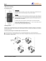
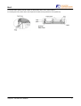
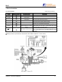
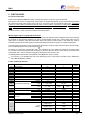
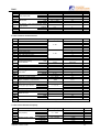
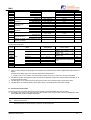
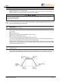
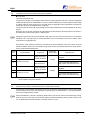
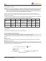
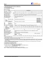
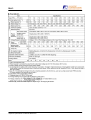
DRAFT
STARTING GUIDE
FRENIC Eco . FRN-F1
Fuji Electric frequency inverter
for HVAC applications
3-phase 400V
0.75 – 500kW
Fuji Electric GmbH . Goethering 58 . 63067 Offenbach/Main . Germany
Tel.: +49 (0)69 669029-0 . Fax +49 (0)69 669029-58 . [email protected] . www.fujielectric.de
FRN-F1
CONTENT
Chapter
Page
1.
SAFETY INFORMATION AND CONFORMITY TO STANDARDS……………………………………………...
1
1.1
Safety Information……………………………………………………………………………………………………
1
1.2
Conformity to Standards……………………………………………………………………………………………..
3
1.2.1
Conformity to European Standards………………………………………………………………………………...
3
1.2.2
Conformity to Low Voltage Directive……………………………………………………………………………….
3
2.
MECHANICAL INSTALLATION……………………………………………………………………………………..
4
2.1
Installing the Inverter…………………………………………………………………………………………………
4
2.2
Mounting direction……………………………………………………………………………………………………
4
2.3
Removing and Mounting the Terminal Block cover and the Front Cover………………………………………
4
3.
ELECTRICAL INSTALLATION……………………………………………………………………………………...
6
3.1
Power Terminals……………………………………………………………………………………………………...
6
3.2
Control Terminals……………………………………………………………………………………………………..
7
3.2.1
Control Terminals Connection………………………………………………………………………………………
8
4.
OPERATION USING THE KEYPAD………………………………………………………………………………..
9
5.
QUICK STARTING COMMISSIONING…………………………………………………………………………….
10
5.1
Running the Motor for a Test………………………………………………………………………………………..
10
5.1.1
Inspection and preparation prior to powering on………………………………………………………………….
10
5.1.2
Turning on power and checking…………………………………………………………………………………….
10
5.1.3
Preparation before running the motor for a test--Setting function code data………………………………….
10
5.1.4
Procedure for Test Run………………………………………………………………………………………………
11
5.2
Operation………………………………………………………………………………………………………………
11
6.
FUNCTION CODES………………………………………………………………………………………………….
12
6.1
Function Codes Tables………………………………………………………………………………………………
12
6.2
Overview of Function Codes………………………………………………………………………………………..
14
7.
PROTECTIVE FUNCTIONS………………………………………………………………………………………...
22
7.1
Protection / Maintenance Function (Parameter H98)…………………………………………………………….
22
7.2
Dew Condensation Protection (Parameter J21)…………………………………………………………………..
23
8.
SPECIFICATIONS AND EXTERNAL DIMENSIONS……………………………………………………………..
24
8.1
Inverter Specifications……………………………………………………………………………………………….
24
8.1.1
Standard Model – IP20 / IP00………………………………………………………………………………………
24
8.1.2
Semi standard – IP54 with integral EMC filter and DCR…………………………………………………………
26
I
FRN-F1
8.2
External Dimensions…………………………………………………………………………………………………
27
8.2.1
Inverter Standard Models..............................................................................................................................
27
8.2.2
Inverter IP54 Models.....................................................................................................................................
28
8.3
Keypad Dimensions.....................................................................................................................................
29
9.
OPTIONS………………………………………………………………………………………………………………
30
Preface
Thank you for purchasing our FRENIC-Eco series of inverters.
This product is designed to drive a three-phase induction motor for fan and pump applications.
Read through this starting guide and become familiar with proper handling and operation of this product. Please note that this
starting guide should enable you to get familiar with the main functions and should help you to install the inverter. Not all functions
are described here. For more detailed information please refer absolutely to the attached CD-ROM which contains the user manual
(MEH456).
Improper handling might result in incorrect operation, a short life, or even a failure of this product as well as the motor.
Have this manual delivered to the end user of this product. Keep this starting guide and CD-ROM in a safe place until this product is
discarded.
Listed below are the other materials related to the use of the FRENIC-Eco. Read them in conjunction with this starting guide as
necessary.
• FRENIC-Eco User's Manual
(MEH456)
• RS485 Communication User's Manual
(MEH448)
• Catalogue
(MEH442)
• RS485 Communications Card "OPC-F1-RS" Installation Manual (INR-SI47-0872)
• Relay Output Card "OPC-F1-RY" Instruction Manual
(INR-SI47-0873)
• Mounting Adapter for External Cooling "PB-F1" Installation Manual (INR-SI47-0880)
• Panel-mount Adapter "MA-F1" Installation Manual
(INR-SI47-0881)
• Multi-function Keypad "TP-G1" Instruction Manual
(INR-SI47-0890-E)
• FRENIC Loader Instruction Manual
(INR-SI47-0903-E)
The materials are subject to change without notice. Be sure to obtain the latest editions for use.
II
FRN-F1
1. SAFETY INFORMATION AND CONFORMITY TO STANDARDS
1.1 Safety Information
Read this manual thoroughly before proceeding with installation, connections (wiring), operation, or maintenance and inspection.
Ensure you have sound knowledge of the device and familiarize yourself with all safety information and precautions before
proceeding to operate the inverter.
Safety precautions are classified into the following two categories in this manual.
Application
•
•
•
FRENIC-Eco is designed to drive a three-phase induction motor. Do not use it for single-phase motors or for other purposes. Fire or an accident
could occur.
FRENIC-Eco may not be used for a life-support system or other purposes directly related to the human safety.
Though FRENIC-Eco is manufactured under strict quality control, install safety devices for applications where serious accidents or material losses
are foreseen in relation to the failure of it. An accident could occur.
Installation
•
•
Install the inverter on a nonflammable material such as metal. Otherwise fire could occur.
Do not place flammable matter nearby. Doing so could cause fire.
•
•
Do not support the inverter by its terminal block cover during transportation. Doing so could cause a drop of the inverter and injuries.
Prevent lint, paper fibers, sawdust, dust, metallic chips, or other foreign materials from getting into the inverter or from accumulating on the heat
sink. Otherwise, a fire or an accident might result.
Do not install or operate an inverter that is damaged or lacking parts. Doing so could cause fire, an accident or injuries.
Do not get on a shipping box.
Do not stack shipping boxes higher than the indicated information printed on those boxes. Doing so could cause injuries.
•
•
•
Maintenance and inspection, and parts replacement
•
•
•
•
Turn the power OFF and wait for at least five minutes for models of 30 kW or below, or ten minutes for models of 37 kW or above, before starting
inspection. Further, check that the LED monitor is unlit, and check the DC link bus voltage between the P (+) and N (-) terminals to be lower than
25 VDC. Otherwise, electric shock could occur.
Maintenance, inspection, and parts replacement should be made only by qualified persons.
Take off the watch, rings and other metallic matter before starting work.
Use insulated tools. Otherwise, electric shock or injuries could occur.
Disposal
•
Handle the inverter as an industrial waste when disposing of it. Otherwise injuries could occur.
Others
•
Never attempt to modify the inverter. Doing so could cause electric shock or injuries.
Wiring
•
When wiring the inverter to the power source, insert a recommended molded case circuit breaker (MCCB) or residual-current-operated protective
device (RCD)/earth leakage circuit breaker (ELCB) (with overcurrent protection) in the path of power lines. Use the devices within the
recommended current range.
Chapter 1: Safety Information and Conformity to Standards
1
FRN-F1
•
•
•
•
Use wires in the specified size. Otherwise, fire could occur.
Do not use one multicore cable in order to connect several inverters with motors.
Do not connect a surge killer to the inverter's output (secondary) circuit. Doing so could cause fire.
Ground the inverter following Class C or Class D specifications or national/local electric code, depending on the input (primary) voltage of the
inverter. Otherwise, electric shock could occur.
•
•
•
•
Qualified electricians should carry out wiring.
Be sure to perform wiring after turning the power OFF. Otherwise, electric shock could occur.
Be sure to perform wiring after installing the inverter body. Otherwise, electric shock or injuries could occur.
Ensure that the number of input phases and the rated voltage of the product match the number of phases and the voltage of the AC power supply
to which the product is to be connected. Otherwise fire or an accident could occur.
Do not connect the power source wires to output terminals (U, V, and W). Doing so could cause fire or an accident.
Generally, control signal wires are not enforced- insulated. If they accidentally touch any of hot power lines, their insulation coat may break for any
reasons. In such a case, an extremely high voltage may be applied to the signal lines. Make a complete remedy to protect the signal line from
contacting any hot high voltage lines. Otherwise, an accident or electric shock could occur.
•
•
•
•
Wire the three-phase motor to terminals U, V, and W of the inverter, aligning phases each other. Otherwise injuries could occur.
The inverter, motor and wiring generate electric noise. Take care of malfunction of the nearby sensors and devices. To prevent the motor from
malfunctioning, implement noise control measures. Otherwise an accident could occur.
Setting control switches
•
Before setting up any internal control switches, turn OFF the power, wait more than five minutes for models of 30 kW or below, or ten minutes for
models of 37 kW or above, and make sure, using a multimeter or a similar instrument, that the DC link bus voltage between the terminals P (+)
and N (-) has dropped below a safe voltage (+25 VDC). Otherwise electric shock could occur.
Operation
•
Be sure to install the terminal block cover and the front cover before turning the power ON. Do not remove the covers while power is applied.
Otherwise electric shock could occur.
•
•
•
Do not operate switches with wet hands. Doing so could cause electric shock.
If the retry function has been selected, the inverter may automatically restart and drive the motor depending on the cause of tripping.
(Design the machinery or equipment so that human safety is ensured after restarting.)
If the stall prevention function (current limiter), automatic deceleration, and overload prevention control have been selected, the inverter may
operate at an acceleration/deceleration time or frequency different from the commanded ones. Design the machine so that safety is ensured even
in such cases. Otherwise an accident could occur.
The STOP key is only effective when function setting (Function code F02) has been established to enable the STOP key. Prepare an emergency
stop switch separately. If you disable the STOP key priority function and enable operation by external commands, you cannot emergency-stop the
inverter using the STOP key on the built-in keypad.
If an alarm reset is made with the Run command signal turned ON, a sudden start will occur. Ensure that the Run command signal is turned OFF
in advance. Otherwise an accident could occur.
If you enable the "restart mode after instantaneous power failure" (Function code F14 = 3, 4, or 5), then the inverter automatically restarts running
the motor when the power is recovered. (Design the machinery or equipment so that human safety is ensured after restarting.)
If you set the function codes wrongly or without completely understanding this instruction manual and the FRENIC-Eco User's Manual (MEH456),
the motor may rotate with a torque or at a speed not permitted for the machine. An accident or injuries could occur.
Do not touch the inverter terminals while the power is applied to the inverter even if the inverter stops. Doing so could cause electric shock.
•
•
•
•
Do not turn the main circuit power (circuit breaker) ON or OFF in order to start or stop inverter operation. Doing so could cause failure.
Do not touch the heat sink because they become very hot. Doing so could cause burns.
Setting the inverter to high speeds is easy. Before changing the frequency (speed) setting, check the specifications of the motor and machinery.
The brake function of the inverter does not provide mechanical holding means. Injuries could occur.
•
•
•
•
•
GENERAL PRECAUTIONS
Drawings in this manual may be illustrated without covers or safety shields for explanation of detail parts. Restore the covers and shields in the
original state and observe the description in the manual before starting operation.
Chapter 1: Safety Information and Conformity to Standards
2
FRN-F1
1.2 Conformity to Standards
1.2.1 .Conformity to European Standards
The CE Approved on Fuji products indicates that they comply with the essential requirements of the Electromagnetic Compatibility
(EMC) Directive 89/336/EEC issued by the Council of the European Communities and the Low Voltage Directive 73/23/EEC.
Only the models with a built-in EMC-compliant filter that bear a CE Approved are compliant with the EMC Directive.
Inverters that bear a CE Approved are compliant with the Low Voltage Directive.
¦ The FRENIC-Eco series of inverters with conformity to the following standards:
Low Voltage Directive
EN50178:1997
EMC Directives EN61800-3:1996 + A11: 2000
EN55011: 1998 + A1:1999
CAUTION
The FRENIC-Eco series of inverters are categorized as a "restricted sales distribution class" provided in the EN61800-3. When you
use these products with any home appliance or office equipment, you may need to take appropriate countermeasures to reduce or
eliminate any noise emitted from these products.
1.2.2 Conformity to Low Voltage Directive
General-purpose inverters are subject to the regulations set forth by the Low Voltage Directive in Europe. Fuji has obtained a
certification of compliance from a European test organization for its FRENIC-Eco series inverters and labels them with a CE
Approved, which is a self-declaration with conformity to the Low Voltage Directive.
Considerations when using FRENIC-Eco as a product with conformity to Low Voltage Directive
If you wish to use a FRENIC-Eco series inverter as a product with conformity to the Low Voltage Directive, refer to the related
guidelines.
Chapter 1: Safety Information and Conformity to Standards
3
FRN-F1
2. Mechanical Installation
2.1 Installing the Inverter
Mounting base
The inverter should be mounted on a base made of material that can withstand heat sink
temperature, which can rise up to 90ºC approx. during inverter operation.
Clearances
Ensure that the minimum clearances indicated are maintained at all times. When installing the
inverter in the enclosure of your system, take extra care with ventilation inside the enclosure
as the temperature around the inverter will tend to increase. Do not install the inverter in a
small enclosure with poor ventilation.
*For 37Kw or above a 50 mm clearance is needed instead of 10 mm (left and right sides).
As long as the ambient temperature is 40°C or lower, 5.5 kW or lower inverters may be
mounted side-by-side without any gap between them.
For others inverters, please follow the clearances needed.
2.2 Mounting Direction
Horizontal layout is recommended when two or more inverters are to be installed in an equipment or enclosure. If it is necessary to
mount the inverters vertically, install a partition plate or the like between the inverters so that any heat radiating from an inverter will
not affect the one/s above.
2.3 Removing and Mounting the Terminal Block (TB) Cover and the Front Cover
To remove the TB cover, loosen the fastening screw on it, hold the dimple (labelled “PULL”), and pull it up towards you.
To remove the front cover, hold it with both hands, slide it downward, disengage the latch at the top from the inverter, tilt the front
cover toward you, and pull it upward.
Chapter 2: Mechanical Installation
4
FRN-F1
For inverters with a capacity of 30 kW or below (for others please refer to user's manual chapter 2).
For mounting the covers, please refer to next snapshots and follow removing instructions in the opposite way.
Chapter 2: Mechanical Installation
5
FRN-F1
3. Electrical Installation
3.1. Power Terminals
Symbol
* Perform wiring as necessary
Wiring procedure
Terminal function
L1/R, L2/S, L3/T
Main power inputs
U, V, W
Inverter outputs
R0, T0
*
P1, P(+)
*
P(+), N(-)
*
R1, T1
*
Gx2
Description
Connect the 3-phase input power lines.
Connect a 3-phase motor
Auxiliary power input for the
control circuit
For a backup of the control circuit power supply, connect AC power
lines same as that of the main power input.
Connect a DC reactor (DCR) for improving power factor (an option
DC reactor connection
for the inverter whose capacity is 55 kW or below).
Connect a DC link bus of other inverter(s). An optional regenerative
DC link bus
converter is also connectable to these terminals.
Auxiliary power input for the fans Normally, no need to use these terminals. Use these terminals for an
(Refer to chapter 8.4.1 of user's auxiliary power input of the fans in a power system using a power
manual)
regenerative PWM converter (RHC series).
Grounding terminals for the inverter’s chassis (or case) and motor.
Earth one of the terminals and connect the grounding terminal of the
Grounding for inverter and motor
motor. Inverters provide a pair of grounding terminals that function
equivalently.
Switching connectors (for models 400 V series 55 kW or above. Refer to chapter 8.4.1 of user's manual.)
Chapter 3: Electrical Installation
6
FRN-F1
3.2. Control Terminals
The FRENIC ECO inverter has 7 digital inputs (two fixed and five programmable), 3 programmable transistor outputs and 2 relay
outputs (one fixed and one programmable).
Symbols
Type
Programmable
Example of use
Description
PLC
Connects to PLC output
signal power supply
--
--
To turn ON or OFF digital inputs using a
relay or a PLC.
24VDC max. current 50mA
CM
Digital common
--
--
Two common terminals for digital input
signal terminals
FWD
Run forward command
YES
--
External run command UP
REV
Run reverse command
YES
--
External run command DOWN
X1-X5
Digital inputs
YES
Speed selection
Coast to stop
etc.
Programmable digital inputs
Program the required function in
parameters E01 through E05
Y5 A/C
General purpose relay
output
YES
MC control signal
Inverter ready
30 A,B,C
Alarm relay output
YES
Signal to control system that the
inverter has an alarm
Y1-Y3
Transistor outputs
YES
Same as relay output Y5 / 30A
Programmable transistor outputs.
Program the required function in
parameters E20 through E22
CMY
Transistor output common
--
--
Common terminal for transistor output
signal terminals
Electrical specification for digital inputs (X1 to X5):
Item
Programmable relay contact output.
Program the required function in
parameters E24 / E27
Electrical specification for transistor outputs:
Min.
Max.
ON level
0V
2V
OFF level
22 V
27V
ON level
22 V
27V
OFF level
0V
2V
Maximum load current at ON
50 mA
Operation current at ON
(Input voltage is at 0V)
2.5 mA
5 mA
Leakage current at OFF
0.1 mA
Allowable leakage current at OFF
-
0.5 mA
Operation
voltage
(SINK)
Operation
voltage
(SOURCE)
Electrical specification for relay contact outputs:
Chapter 3: Electrical Installation
Item
Operation
voltage
Max.
ON level
3V
OFF level
27 V
48 VDC, 0.5 A
7
FRN-F1
3.2.1 Control Terminals Connection
Digital inputs and outputs can be operated both in NPN (sink) and PNP (source) logic.
a) DIGITAL INPUTS: Refer to the user's manual MEH456 for connection examples.
SW1 SINK
SW1 SOURCE
The switch SW1 located on the control board defines the logic
used for digital inputs. Factory default setting is source.
? SINK LOGIC: Digital input ON giving 0 volts.
? SOURCE LOGIC: Digital input ON giving 24 volts.
b) TRANSISTOR OUTPUTS: Refer to the user's manual MEH456 for connection examples.
To decide what logic to use, there is no switch as before.
Connecting “PLC” terminal to the transistor common “CMY” terminal you will have PNP logic.
Connecting “CM” terminal to the transistor common “CMY” terminal you will have NPN logic.
c) RELAY OUTPUTS:
Y5A/C RELAY: you can switch its output mode between “Active ON”
(the terminals [Y5A] and [Y5C] are short-circuited if the signal is
active) and “Active OFF” (the terminals [Y5A] and [Y5C] are opencircuited if the signal is active).
30A
30B
30C
Y5A
30A/B/C RELAY: switching of the normal/negative logic output is
applicable to the following two contact outputs: "Terminals [30A] and
[30C] are short-circuited for ON signal output (Active ON)" or "the
terminals [30B] and [30C] are short-circuited (non-excite) for ON
signal output (Active OFF)."
Chapter 3: Electrical Installation
Y5C
8
FRN-F1
4. OPERATION USING THE KEYPAD
LED monitor
As shown in the figure at right, the keypad
consists of a four-digit LED monitor, 5 LED
indicators, and six keys.
The keypad allows you to start and stop the
motor, monitor running status, and switch to the
menu mode. In the menu mode, you may set
the function code data, monitor I/O signal
states, maintenance information, and alarm
information.
Item
LED
indicators
Program/
Reset key
RUN key
Function/
Data key
STOP key
Up key
Monitor,
LED indicators
and Keys
Down key
Functions
Four-digit, 7-segment LED monitor which displays the following according to the operation modes.
n In Running Mode:
Running status information (e.g., output frequency, current, and voltage)
n In Programming Mode: Menus, function codes and their data
n In Alarm Mode:
Alarm code, which identifies the error factor if the protective function is
activated.
LED
Monitor
Program/Reset key which
n In Running Mode:
n In Programming Mode:
n In Alarm Mode:
switches the operation modes of the inverter.
Pressing this key switches the inverter to Programming Mode.
Pressing this key switches the inverter to Running Mode.
Pressing this key after removing the error factor will switch the inverter
to Running Mode.
Function/Data key which switches the operation you want to do in each mode as follows:
n In Running Mode: Pressing this key switch the information to be displayed concerning the
status of the inverter (output frequency (Hz), output current (A), output
voltage (V), etc.).
n In Programming Mode: Pressing this key displays the function code and sets the data entered
with and keys.
n In Alarm Mode:
Pressing this key displays the details of the problem indicated by the
alarm code that has come up on the LED monitor.
Operation
Keys
RUN key. Press this key to run the motor.
STOP key. Press this key to stop the motor.
and
UP and DOWN keys. Press these keys to select the setting items and change the function data
displayed on the LED monitor.
RUN LED
Lights when any run command to the inverter is active, In Programming and Alarm modes, you
cannot run the inverter even if the indicator lights.
KEYPAD
CONTROL LED
Lights when the inverter is running by the run command from the
LED
Indicators
Unit and Mode expression
by the three LED
indicators
key.
The lower 3 LED indicators identify the unit of numeral displayed on the LED monitor in Running
Mode by combination of lit and unlit states of them in the category shown below.
kW, A, Hz, r/min and m/min
While the inverter is in Programming Mode, the LEDs at both ends of the lower indicators light.
In Programming Mode: ¦ Hz ? A ¦ kW
Chapter 4: Keys and LED on the Keypad
9
FRN-F1
5. QUICK STARTING COMMISSIONING
5.1
Running the Motor for a Test
5.1.1 Inspection and preparation prior to powering on
Check the following prior to starting powering on.
(1) Check if connection is correct.
Especially check if the power wires are connected to the inverter input terminals L1/R, L2/S and L3/T, and output
terminals U, V and W respectively and that the grounding wires are connected to the ground electrodes correctly. Note
that FRENIC-Eco series inverter is designed for three phase input and driving three phase motors.
•
•
Do not connect power supply wires to the inverter output terminals U, V, and W. Otherwise, the inverter may
be broken if you turn the power on.
Be sure to connect the grounding wires of the inverter and the motor to the ground electrodes.
Otherwise, electric shock may occur.
(2) Check for short circuits between terminals and exposed live
parts and ground faults.
(3) Check for loose terminals, connectors and screws.
(4) Check if the motor is separated from mechanical equipment.
(5) Turn the switches off so that the inverter does not start or
operate erroneously at power-on.
(6) Check if safety measures are taken against runaway of the
system, e.g., a defense to protect people from unexpectedly
Figure 5.1 Connection of Main Circuit Terminals
approaching your power system.
5.1.2 Turning on power and checking
Turn the power on and check the following points. This is
a case when no function code data is changed from the
factory setting.
(1) Check if the LED monitor displays "*00 " (means that the
frequency command is 0 Hz) that is blinking. (See Figure
5.2.)
If the LED monitor displays numbers except "*00 " then
press the / key to set "*00 " as the frequency
command.
(2) Check if a built-in cooling fan rotates.
Figure 5.2 Display of the LED Monitor after Power-on
5.1.3 Preparation before running the motor for a test--Setting function code data
Before starting running the motor, set function code data specified in Table 5.1 to the motor ratings and your system
design values. For the motor, check the rated values printed on the nameplate of the motor. For your system design
values, ask system designers about them.
&
For details about how to change function code data, refer to Chapter 4. Refer to the function code H03 in Chapter 6
"FUNCTION CODES" for the factory default setting of motor parameters. If any of them is different from the default setting,
change the function code data.
Chapter 5: Quick Starting Commissioning
10
FRN-F1
Table 5.1 Settings of Function Code Data before Driving the Motor for a Test
Function
code
Name
Function code data
F 04
Base frequency
F 05
Rated voltage (at base
frequency)
F 03
Maximum frequency
F 07
Acceleration time 1*
F 08
Deceleration time 1*
P 02
P 03
P 99
Motor parameter (Rated capacity)
Motor ratings (printed on the
Motor parameter (Rated current)
nameplate of the motor)
Motor Selection
Motor ratings (printed on the
nameplate of the motor)
System design values
* For a test-driving of the motor,
increase values so that they are
longer than your system design
values. If the set time is short, the
inverter may not start running the
motor.
Factory setting
50.0 (Hz)
0 (V) (Output voltage interlocked with the input voltage)
50.0 (Hz)
20.0 (sec)
20.0 (sec)
Applicable motor rated capacity
Rated current of applicable motor
0: Characteristic of ICE motor.
5.1.4 Procedure for Test Run
(1) Turn the power on and check that the LED monitor blinks while indicating the *00 Hz frequency.
(2) Set the frequency to a low frequency such as 5 Hz, using the
/
key. (Check that frequency command blinks on
the LED monitor.)
(3) Press the key to start running the motor in the forward direction. (Check that the frequency command is displayed
on the LED monitor correctly.)
(4) To stop the motor, press the key.
<Check the following points>
• Check if the direction of rotation is forward.
• Check for smooth rotation without motor humming or excessive vibration.
• Check for smooth acceleration and deceleration.
When no abnormality is found, press the key again to start driving the motor, and increase the frequency command
using the / key. Check the above points for the test-driving of the motor.
---------------------------------------------------------------------------------------------------------------------------------------------------5.2 Operation
After confirming normal operation by performing a test run, make mechanical connections (connections of the machine
system) and electrical connections (wiring and cabling), and set the necessary parameters properly before starting a
production run.
Depending on the conditions of the production run, further adjustments can be required, such as adjustments of torque
boost (F09), acceleration time (F07), and deceleration time (F08). Make sure to set relevant function codes properly.
Chapter 5: Quick Starting Commissioning
11
FRN-F1
6. FUNCTION CODES
6.1 Function Codes Tables
Function codes enable the FRENIC-Eco series of inverters to be set up to match your system requirements.
Each function code consists of a 3-letter string. The first letter is an alphabet that identifies its group and the following two letters
are numerals that identify each individual code in the group. The function codes are classified into eight groups: Fundamental
Functions (F codes), Extension Terminal Functions (E codes), Control Functions of Frequency (C codes), Motor Parameters (P
codes), High Performance Functions (H codes), Application Functions (J codes), Link Function (y codes) and. Option Function (o
codes) To determine the property of each function code, set data to the function code.
For Option function (o codes), refer to the instruction manual for the option.
n Using negative logic for programmable I/O terminals
The negative logic signaling system can be used for the digital input and output terminals by setting the function codes specifying
the properties for those terminals. Negative logic refers to inverted ON/OFF (logical value 1 (true)/0 (false)) state of input or
output signal. An ON-active signal (the function takes effect if the terminal is short-circuited.) in the normal logic system is
functionally equivalent to OFF-active signal (the function takes effect if the terminal is opened.) in the negative logic system.
To set the negative logic system for an I/O signal terminal, display data of 1000s (by adding 1000 to the data for the normal logic)
in the corresponding function code and then press the key.
For example, if a coast-to-stop command (BX: data = 7) is assigned to any one of digital input terminals [X1] to [X3] by setting
any of function codes E01 through E03, then turning (BX) on will make the motor coast to a stop. Similarly, if the coast-to-stop
command (BX: data = 1007) is assigned, turning (BX) off will make the motor coast to a stop.
The following tables list the function codes available for the FRENIC-Eco series of inverters.
& If you find any [-] (not available here) mark in the related page column of the function code tables, refer to FRENIC-Eco
User’s Manual (MEH456) for details.
F codes: Fundamental functions
Code
F00
F01
F02
F03
F04
F05
F07
F08
F09
F10
F11
Name
Data Protection
Frequency command 1
Operation method
Maximum frequency1
Base frequency 1
Rated voltage 1
Acceleration time 1
Deceleration time 1
Torque boost 1
Function
Electric thermal overload relay 1
F12
F14
F15
F16
F18
F20
F21
F22
F23
F25
Level
Time
Restart after moment. power failure
Frequency limiter
high
low
Bias Frequency 1
DC Brake
Frequency
Level
Time
Starting frequency
Stopping frequency
Motor Sound
F26
Chapter 6: Function Codes
Carrier
frequency
Setting Range
Factory default
0/1
0~3/5/7
0~4
25 ~ 120Hz
25 ~ 120Hz
0 / 160 ~ 500V
0.00 ~ 3600s
0.00 ~ 3600s
0.0 ~ 20.0
1/2
0.0 (Disable)
1 ~ 135% IN Mot.
0
0
0
50Hz
50Hz
400V
20s
20s
Depending on the rated capacity
1
Nominal rated current (100%) of
the motor
5.0 (22kW or 10.0 (30kW or
below)
below
1
70.0Hz
0.0Hz
0.00%
0.0Hz
0%
0.00s
0.5Hz
0.2Hz
0.5 ~ 75min
0~5
0~120Hz
0~120Hz
-100.00~+100.00 %
0.0~60.0Hz
0 ~ 100%
0 / 0.01 ~ 30.0s
0.1 ~ 60.0Hz
0.1 ~ 60.0Hz
0.75~15 kHz
(22kW or below)
0.75~10 kHz
(30kW to 75kW)
0.75~6 kHz
(90kW or above)
See
Page:
14
15
16
16
16
16
16
17
17
17
17
18
19
15kHz
19
10kHz
19
6kHz
19
12
FRN-F1
F27
F29
F30
F31
F33
F34
F35
F37
F43
F44
Tone
Selection
Analog Output (FMA)
Level
Function
Pulsrate
FMP Terminal
Level
Function
Load selection / Auto torque boost/ Auto energy
saving operation
Selection
Current limiter
Level
0~3
0/1
0~200%
0 ~ 16
25 ~ 6000p/s
0% / 1 ~ 200%
0 ~ 16
0
0
100%
0
1440p/s
0%
0
0~5
1
0~2
20 ~ 120% IN Mot.
0
110%
17
The shaded function codes are applicable to the quick setup
E codes : Extension Terminal functions
Code
Name
E01
E02
E03
E04
E05
E20
E21
E22
E24
E27
E31
X1 Terminal Function
X2 Terminal Function
X3 Terminal Function
X4 Terminal Function
X5 Terminal Function
Y1 Terminal Function
Y2 Terminal Function
Y3 Terminal Function
Y5A / Y5B Terminal Function
30A/B/C Terminal Function
Frequency detection FDT
E34
Overload Early Warning
Current detection
E35
E40
E41
E43
E45
E46
E47
E48
E50
Setting Range
0 ~ 89
0 ~ 99
Level
Level
Timer
Display coefficient A
Display coefficient B
LED Monitor
Function
Selection
Language
Contrast
Speed item
LCD Monitor*3
LED Monitor
Coefficient for speed indication
E51
Display Coefficient for Input W/h data
E52
E61
E62
E63
E64
E65
E80
E81
E98
E99
Keypad (Menu display mode)
Terminal 12
Terminal C1
Terminal V2
Analog input signal selection
Saving of the digital set frequency
Command loss detection
Detect low torque
Terminal command
Level
Level
Timer
FWD
REV
0~120Hz
0 / 1~150% of the inverter
current
0. 1~600.0s
-999.00 ~ 999.00
-999.00 ~ 999.00
0 ~ 17
0/1
0~5
0 ~ 10
0~7
0.01 ~ 200.00
0.000 (Cancel/reset) 0.001
~ 9999
0 ~2
0 ~ 3 / 5 / 20
0/1
0 / 1 ~ 120 / 999
0 ~ 150%
0.01 ~ 600.00s
0 ~ 89
Factory default
6
7
8
11
35
0
1
2
15
99
60Hz
Nominal rated current (100%)
of the motor
10.0s
100
0.0
0
0
1
5
0
30
0.010
0
0
0
0
0
999
20%
20s
98
99
19
The shaded function codes are applicable to the quick setup
C codes: Control functions of frequency
Code
C01
C02
C03
C04
C05
C06
C07
Name
Jump frequency
Multistep frequency setting
Chapter 6: Function Codes
Setting Range
1
2
3
Hysterics
Frequency 1
Frequency 2
Frequency 3
0.0 ~ 120Hz
0.0 ~ 30Hz
0.00 ~ 120.00Hz
Factory default
0.0Hz
0.0Hz
0.0Hz
0.0Hz
0.00Hz
0.00Hz
0.00Hz
13
FRN-F1
C08
C09
C10
C11
C30
C32
C33
C34
C37
C38
C39
C42
C43
C44
C50
C51
C52
C53
Frequency 4
Frequency 5
Frequency 6
Frequency 7
Frequency command 2
Terminal 12
Signal filter
Gain base point
Terminal 1
Signal filter
Gain base point
Terminal V2
Signal filter
Gain base point
Analog input gain
adjustment
Analog input gain
adjustment
Analog input gain
adjustment
Bias Frequency command 1
Bias base point
Base value
Bias PID command 1
Bias base point
Selection of normal / inverse operation for the
frequency command 1
0~3/5/7
0.00 ~ 200.00 %
0.00 ~ 5.00s
0.00 ~ 100.00%
0.00 ~ 200.00 %
0.00 ~ 5.00s
0.00 ~ 100.00%
0.00 ~ 200.00 %
0.00 ~ 5.00s
0.00 ~ 100.00%
0.00Hz
0.00Hz
0.00Hz
0.00Hz
2
100.00%
0.05s
100%
0.00Hz
0.00Hz
0.00Hz
0.00Hz
0.00Hz
0.00Hz
0.00 ~ 100.0%
0.00%
-100 ~ 100%
0.00 ~ 100.00%
0.00%
0.00%
0/1
0
Setting Range
Factory default
4
Nominal rated capacity of the
standard motor
Nominal rated current of the
standard motor
0
14
P codes: Motor parameters
Code
Name
P01
Number of poles
2 ~ 22
P02
Rated capacity
0.01 ~ 1000 kW
Rated current
0.00 ~ 2000A
Auto tuning
No-load current
%R1 Setting
%X Setting
Selection
0/1/2
0.00 ~ 2000A
0.00 ~ 50.00%
0.00 ~ 50.00%
0~4
P03
P04
P06
P07
P08
P99
Motor
20
20
20
Nominal rated value of the standard
motor
0
20
The shaded function codes are applicable to the quick setup
*1
*2
*3
*4
When you make settings from the keypad, the incremental unit is restricted by the number of digits that the LED monitor can
display.
(Example) If the setting range is from -200.00 to 200.00, the incremental unit is:
"1" for -200 to -100, "0.1" for -99.9 to -10.0 and for 100.0 to 200.0, and "0.01" for -9.99 to -0.01 and for 0.00 to 99.99.
The H86 through H91 are displayed, but they are reserved for particular manufacturers. Unless otherwise specified, do not
access these function codes.
The H80 select 0.10 for models of 55 kW or above (400 V series), 0.20 for models 45 kW or below (400 V series).
The H86 select 2 for models of 55 kW or above (400 V series), 0 for models 45 kW or below (400 V series).
6.2 Overview of Function Codes
This section provides an overview of the function codes frequently used for the FRENIC-Eco series of inverter.
& For details of the function codes given below and other function codes not given below, refer to the FRENIC-Eco User’s
Manual (MEH456), Chapter 9 "FUNCTION CODES."
F01
C30
Frequency Command 1
Frequency Command 2
Selects the devices to set the frequency command 1 for driving the motor.
Chapter 6: Function Codes
14
FRN-F1
F01
To do this
0
Enable
and
keys on the built-in keypad. (Refer to Chapter 4 "OPERATION USING THE KEYPAD.")
1
Enable the voltage input to terminal [12] (0 to 10 VDC).
2
Enable the current input to terminal [C1] (4 to 20 mA DC).
3
Enable the sum of voltage and current inputs to terminals [12] and [C1]. See the two items listed above for the
setting range and maximum frequencies.
Note: If the sum exceeds the maximum frequency, the maximum frequency will apply.
5
Enable the voltage input to terminal [V2] (0 to 10 VDC).
7
Enable (UP) and (DOWN) commands assigned to the digital input terminals
(UP) command (data=17) and (DOWN) command (data=18) to the input terminals [X1] to [X5].
Certain setting means (e.g., communication link and multistep frequency) have priority over these settings. For details,
refer to the block diagram in the FRENIC-Eco User’s Manual (MEH456), Chapter 4, Section 4.2 "Drive Frequency
Command Generator."
F02
Operation Method
Select the source issuing a run command for running the motor.
F02
Running Mode
Source of Run Command
0
Running per keypad
(rotation direction:
determined by terminal
block)
Enables the
key and the
key on the keypad to start and stop the motor. In the
case of a standard keypad, the direction of rotation is determined by the commands
given at terminals FWD and REV.
In the case of a multi-functional keypad, there is no need to specify the direction of
rotation.
1
External signal
Enables the external signals given at terminals FWD and REV to run the motor.
2
Running per keypad
(forward rotation)
Enables the key and the key on the keypad to start and stop the motor. There is
no need to specify the direction of rotation, since only forward rotation is allowed.
In the case of a multi-functional keypad, only the FWD key is effective.
3
Running per keypad
(reverse rotation)
Enables the key and the key on the keypad to start and stop the motor. There is
no need to specify the direction of rotation, since only reverse rotation is allowed.
In the case of a multi-functional keypad, only the REV key is effective.
When function code F02 = 0 or 1, the forward running/stopping function (FWD) and the reverse running /stopping
function (REV) must be assigned to terminals FWD and REV, respectively.
In addition to the function code F02 described above, there are several other means available with priority over F02.
For details, refer to the block diagram in FRENIC-Eco User’s Manual (MEH456), Chapter 4, Section 4.3 "Drive
Command Generator."
Digital input commands (FWD) and (REV) are valid for specifying the motor rotation direction, and the commands
(FWD2) and (REV2) are invalid.
• If you have assigned the (FWD) or (REV) function to the [FWD] or [REV] terminal, you cannot change the setting of
function code F02 while the terminals [FWD] and [PLC]* or the terminals [REV] and [CM]* are short-circuited.
• If you have specified the external signal (F02 = 1) as the running command and have assigned functions other than
the (FWD) or (REV) function to the [FWD] or [REV] terminal, caution should be exercised in changing the settings.
Because, if under this condition you assign the (FWD) or (REV) function to the [FWD] or [REV] terminal while the
terminals [FWD] and [PLC]* or the terminals [REV] and [PLC]* are short-circuited, the motor would start running.
*[PLC] replaces with [CM] for SINK mode.
•
When "Local" is selected by Remote/Local switching, the operation of the keypad concerning run commands varies
with the setting of F02. For details, refer to Chapter 4.
Chapter 6: Function Codes
15
FRN-F1
F03
Maximum Frequency
Sets the maximum frequency to drive the motor.
Setting the frequency out of the range rated for the equipment driven by the inverter may cause damage or a
dangerous situation. Set a maximum frequency appropriate for the equipment.
The inverter can easily set high-speed operation. When changing the speed setting, carefully check the specifications of
motors or equipment beforehand.
Otherwise injuries could occur.
If you modify the data of F03 to apply a higher drive frequency, concurrently change the data of F15 for a high
frequency limiter suitable to the drive frequency.
F04
F05
Base Frequency
Rated Voltage (at base frequency)
These function codes set the base frequency and the voltage at the base frequency essentially required for running the
motor properly.
n Base Frequency (F04)
Set the rated frequency printed on the nameplate located on the motor.
n Rated Voltage (at base frequency) (F05)
Set 0 or the rated voltage printed on the nameplate labeled on the motor.
- If 0 is set, the inverter supplies voltage equivalent to that of the power source of the inverter at the base frequency. In
this case, the output voltage will vary in line with any variance in input voltage.
- If the data is set to anything other than 0, the inverter automatically keeps the output voltage constant in line with the
setting. When any of the automatic torque boost settings, automatic energy saving is active, the voltage settings
should be equal to the rating of the motor.
F07
F08
Acceleration Time 1
Deceleration Time 1
The acceleration time specifies the length of time the frequency increases from 0 Hz to the maximum frequency. The
deceleration time specifies the length of time the frequency decreases from the maximum frequency down to 0 Hz.
Chapter 6: Function Codes
16
FRN-F1
F09
F37
Torque Boost
Load Selection/Auto Torque Boost/Auto Energy Saving Operation
n Torque Boost
• Manual torque boost per F09
In torque boost using F09, you are adding a certain amount of voltage, regardless of the load, to the output voltage that
is determined by the basic V/f characteristics. To secure a sufficient starting torque, manually adjust the output voltage
to optimally match the motor and its load by using F09. Select an appropriate level that guarantees smooth start-up
and yet does not cause over-excitation with no or light load.
Torque boost per F09 ensures high driving stability since the output voltage remains constant regardless of the size of
the load.
Specify the value for function code F09 in ratio (percentage) to the base frequency. At factory shipment, it is preset to a
level that ensures a certain amount (50%) of starting torque.
Specifying a high torque boost level will generate a high torque, but may cause overcurrent due to over-excitation
when there is no or very light load. If you continue to drive the motor, it may overheat. To avoid such a situation, adjust
torque boost to an appropriate level.
These function codes optimize the operation in accordance with the characteristics of the load. Function code F37
specifies V/f pattern, torque boost, and automatic energy saving functions. F09 specifies the amount of torque boost in
order to provide sufficient starting torque.
Data for
F37
0
V/f characteristics
Non-linear torque load
1
2
Constant torque load
3
Non-linear torque load
4
5
Constant torque load
*1
Torque boost
Preset torque boost
manually set by F09
Auto-energy
saving function
Fans and pumps with general
properties
Disabled
Auto-torque boost
Pumps require high starting torque*1
Pumps require high starting torque
(With a motor over excited at no load)
Auto-torque boost
Preset torque boost
manually set by F09
Applicable load
Fans and pumps with general
properties
Enabled
Pumps require high starting torque*1
Pumps require high starting torque
(With a motor over excited at no load)
If a (load torque + acceleration toque) needs 50% or more parts of the constant torque, you have to apply the
linear V/f pattern set by factory defaults.
F10 to Electronic Thermal Overload for Motor Protection
F12
(Select the motor property, overload detection level, and thermal time constant)
F10 through F12 set the thermal characteristics of the motor for electronic thermal simulation, which is used to detect
overload conditions of the motor. More specifically, F10 specifies the motor characteristics, F11 the overload detection
level, and F12 the thermal time constant.
Thermal characteristics of the motor specified by these function codes are also used for the overload early warning.
Therefore, even if you need only the overload early warning, set these characteristics data to function codes F10 and
F12. To disable electronic thermal simulation, set function code F11 to "0.00."
Chapter 6: Function Codes
17
FRN-F1
n Motor Characteristics (F10)
F10 selects the cooling characteristics of the motor--built-in cooling fan or externally powered forced-ventilation fan.
F10
1
2
If the motor is cooled by:
Built-in cooling fan for general-purpose motors (self-cooled)
(The cooling performance will decrease with low frequency operations.)
Forced-ventilation fan powered by an external source for an motor
(The cooling performance will be kept constant regardless of the output frequency.)
n Operation Level (F11)
F11 specifies the level at which an overload condition is to be recognized. Ordinarily, set F11 to 1.0 to 1.1 times the
allowable continuous current (rated current of the motor (P03)) at the rated drive frequency (base frequency) of the
motor. To disable the electronic thermal function, set F11 to 0.00 (no effect).
n Thermal Time Constant (F12)
F12 sets the thermal time constant of the motor. The inverter interprets the time constant as an operation period of the
electronic thermal function. During the specified operation period, the inverter will activate the electronic thermal
function if 150% current of the operation level specified by F11 flows continuously.
The thermal constants of most general-purpose motors are set at about 5 minutes for capacities of 22 kW or below or
about 10 minutes for capacities of 30 kW or above at the time of factory shipment.
Data entry range: 0.5 to 75.0 (minutes, in 0.1-minute increment)
F14
Restart Mode after Momentary Power Failure
(Mode selection)
These function codes specify the mode and action to be taken in the event of a momentary power failure (such as
tripping and restart).
n Restart after Momentary Power Failure (mode selection) (F14)
F14
Mode
Description
1
No restart after
momentary power
failure
(Trip immediately)
As soon as the voltage of the DC link circuit drops below the lower limit after a
momentary power failure, the output of the inverter is shut down, with an
undervoltage alarm "LU" displayed, and the motor enters a coast-to-stop state.
2
No restart after
momentary power
failure
(Trip after recovery of
power)
As soon as the voltage of the DC link circuit drops below the lower limit after a
momentary power failure, the output of the inverter is shut down, without an
undervoltage alarm "LU" displayed, and the motor enters a coast-to-stop state.
When power is restored, an undervoltage alarm "LU" is displayed, while the
motor remains in coast-to-stop state.
3
Restart after
momentary power
failure
(Continuous running)
When the voltage of the DC link circuit drops below the lower limit after a
momentary power failure, continuous running control is invoked. Continuous
running control regenerates kinetic energy due to the load’s moment of inertia by
slowing down the motor and prolongs the running time. When an undervoltage
condition is detected due to a lack of energy to be regenerated, the output
frequency at that time is saved, the output of the inverter is shut down, and the
motor enters a coast-to-stop state.
When power is restored, if a run command has been received restart takes place
at the frequency saved at the time of the power failure. This setting is ideal for
applications with a large moment of inertia such as a fan.
4
Restart after
momentary power
failure
(Restart at the
frequency at which
As soon as the voltage of the DC link circuit drops below the lower limit after a
momentary power failure, the output frequency at the time is saved, the output of
the inverter is shut down, and the motor enters a coast-to-stop state.
When power is restored, if a run command has been received restart begins at
the frequency saved at the time of the power failure. This setting is ideal for
Chapter 6: Function Codes
18
FRN-F1
5
the power failure
occurred)
applications with a moment of inertia large enough not to slow down the motor
quickly (such as a fan) after it enters a coast-to-run state as a result of a
momentary power failure.
Restart after
momentary power
failure
(restart at starting
frequency)
After a momentary power failure, when power is restored and a run command is
received, restart begins at the start frequency command by function code F23.
This setting is ideal for applications with a heavy load having a small moment of
inertia, in which the motor speed quickly goes down to zero as soon as it enters
a coast-to-stop state as a result of a momentary power failure (such as a pump).
If you select restart after momentary power failure (F14 = 3, 4 or 5), the inverter will automatically restart running the
motor when power is recovered.
The machine should be so designed that human body and peripheral equipment safety is ensured even after
automatic restarting.
Otherwise an accident could occur.
F16
Frequency Limiter (Low)
Frequency limiter (low) F16 sets the lower limit of the output, as shown below.
F26
Motor Sound (Carrier frequency)
n Motor Sound (Carrier frequency) (F26)
This function controls the carrier frequency so as to reduce a sound noise issued by the motor or inverter itself, and to
decrease a leakage current from the main output wirings.
E52
Keypad (Menu display mode)
Selects the menu display mode on the built-in keypad as shown in the table below.
Menu #
LED monitor
shows:
0
0.fnc
Quick Setup
Quick setup function code
1
1.F__
Data Setting F to o codes
One of F through o function code
2
2.rEP
Data Checking
New function code data
(for confirmation after modification)
3
3.oPE
Drive Monitoring
Running status
Chapter 6: Function Codes
Function
What is displayed:
19
FRN-F1
4
4.l_o
5
5.CHE
6
6.AL
7
7.CPY
I/O Checking
Status of DIO, and AIO
Maintenance Information Display
Maintenance information
Alarm Information Display
Alarm information
Data Copying
Copied function code
&
For details of each menu item, refer to Chapter 4, "OPERATION USING THE KEYPAD."
P02
Motor (Rated capacity)
P02 specifies the rated capacity of the motor. Enter the rated value shown on the nameplate of the motor.
Data for P02
0.01 to 1000
P03
Unit
Dependency on function code P99
kW
P99 = 0, 3 or 4
HP
P99 = 1
Motor (Rated current)
P03 specifies the rated current of the motor. Enter the rated value shown on the nameplate.
P04
Motor (Auto-tuning)
This function automatically detects the motor parameters and saves them in the inverter’s internal memory. Basically,
you do not need to perform tuning if you connect the inverter to a standard motor in standard applications.
In any of the following cases, the default settings may not produce the best results for auto torque boost, torque
calculation monitoring, or auto energy saving, since the standard settings of motor parameters for motors are not
applicable. In such a case, perform auto-tuning using this feature.
• The motor to be driven is a non-standard product.
• The cabling between the motor and the inverter is long.
• A reactor is inserted between the motor and the inverter.
Tuning procedure
1) Preparation
Referring to the rating plate on the motor, set the following function codes to their nominal ratings:
• F04: Base frequency
• F05: Rated voltage (at Base frequency)
• P02: Rated capacity
• P03: Rated current
2) Selection of Tuning Process
Check the situation of the machine system and choose between "Tuning while the motor is stopped (P04 = 1)" or
"Tuning while the motor is running (P04 = 2)."
In the case of "Tuning while the motor is stopped (P04 = 1)", 'static tuning' measures the primary resistance (%R1) of
the motor and leakage reactance (%X) of the base frequency when the motor is stopping and writes both values in P07
and P08 automatically.
In the case of "Tuning while the motor is running (P04 = 2)", 'dynamic tuning' measures the primary resistance (%R1)
of the motor and leakage reactance (%X) of the base frequency when the motor is stopping. It measures also the noload current (I0) when the motor is running approximately 50% of the base frequency and writes these values in P06,
P07 and P08 automatically.
The 'dynamic tuning' (P04 = 2) can be carried only with a freewheel running motor without load and gear. Please adjust
the acceleration and deceleration times (F07 and F08) as well and set the rotation direction properly so that it matches
the actual rotation direction of the machine system.
Chapter 6: Function Codes
20
FRN-F1
3)
Preparation of Machine System
Perform appropriate preparations on the motor and its load, such as disengaging the coupling and deactivating the safety
device.
4)
Perform tuning
Set function code P04 to "1" or "2" and press the
key. (The blinking of 1 or 2 on the LED monitor will slow down.)
Enter a Run command for the rotation direction you have chosen. The factory default setting is "forward rotation upon
pressing the key on the keypad." To switch to reverse rotation, change the setting of function code F02.
The display of 1 or 2 stays lit, and tuning takes place while the motor is stopped.
(Maximum tuning time: approximately 40 sec.)
If the function code P04 = 2, the motor is accelerated to approximately 50% of the base frequency and then tuning
takes place. Upon completion of measurements, the motor will coast-to-stop.
(Estimated tuning time: Acceleration time + 10 sec + Deceleration time)
If the terminal signal (FWD) or (REV) is selected as the Run command (F02 = 1), end will appear upon completion of
the measurements.
The Run command is turned OFF and the tuning completes, with the next function code p06 displayed on the keypad
(the Run command given through the keypad or the communication link is automatically turned OFF).
¢ Errors during Tuning
Improper tuning would negatively affect the operation performance and, in the worst case, could even cause hunting or
deteriorate precision. Therefore, if the inverter finds any abnormality in the results of the tuning or any error in the process of
the tuning, it will display er7 and discard the tuning data.
Listed below are the abnormal or error conditions that can be recognized during tuning.
Abnormal / error
condition
Description
Abnormal result of
tuning
An inter-phase imbalance has been detected;
Tuning has resulted in an abnormally high or low value of a parameter.
Abnormal output
current
An abnormally high current has been caused during tuning.
Sequence error
During tuning, the Run command has been turned OFF, or forced STOP, coast-to-stop
command (BX), dew condensation protection (DWP), or a similar abnormal command has
been received.
Limitation exceeded
During tuning, a certain limitation has been reached or exceeded;
The maximum output frequency or the peak limiter for output frequency has been reached or
exceeded.
Other alarm
An undervoltage or an alarm has been occurred.
condition
If any of these conditions has occurred, either eliminate the abnormal or error factor(s) and perform tuning again, or
contact your Fuji Electric representative.
If a filter other than Fuji optional output filter (OFL-£££-4A) is connected to the inverter's output (secondary) circuit,
the result of tuning can be unpredictable. When you replace an inverter, take note of the old inverter’s settings for the
primary resistance %R1, the leakage reactance %X, and the no-load current, and set those values to the new
inverter’s function codes.
P99
Motor Selection
Automatic control such as auto-torque boost, auto-energy saving or electronics thermal simulation (Overheat protection
of a motor) uses the motor parameters and characteristics. To match the property of a control system with that of the
motor, select characteristics of the motor, and clear the old motor parameter setting H03 to "3." Then, data of P03, P06,
P07, and P08 and the old related internal data will be automatically updated. According to the motor model follow the
description below to enter the data necessary for motor setup.
• Standard motors (Current standard): P99 = 0 or 4
Chapter 6: Function Codes
21
FRN-F1
7. PROTECTIVE FUNCTIONS
7.1 Protection / Maintenance Function (Parameter H98)
Possibility to enable or disable of:
n Automatic lowering of the carrier frequency
n Protection against input phase loss
n Protection against output phase loss
n Judgment and criteria on the life of the main circuit capacitor
n Protection against DC fan lock
Automatic DEC function for carrier frequency
Allows you to enable a mechanism for avoiding an overheat trip or overload trip. If enabled, this mechanism lowers the carrier
frequency of the inverter before tripping (with an alarm of 0h1, 0h3 or 0lu) when an overheating of the heat sink or an overload
condition occurs in the inverter as a result of overload, an abnormal ambient temperature, or a problem in the cooling system. This
feature is useful for a critical machine installation where it is extremely important to keep the motor running all the time. Note that if
this feature is enabled the motor noise increases.
Protection against input phase loss (lin )
Upon detecting an excess stress inflicted on the apparatus connected to the main circuit because of a phase loss or an inter-phase
imbalance in the 3-phase power supplied to the inverter, this feature stops the inverter and displays an alarm (lin ).
In configurations where only a light load is driven or a DC reactor is connected, a phase loss or an inter-phase imbalance
may not be detected because of the relatively small stress on the apparatus connected to the main circuit.
Protection against output phase loss (0pl: Output Phase Loss)
Upon detecting a phase loss in the output while the inverter is running, this feature stops the inverter and displays an alarm (0pl). In
configurations where a magnetic contactor is installed in the power output circuit, if the magnetic contactor goes OFF during
operation, all the phases will be lost. In such a case, this protection feature does not work.
Selection of criteria for judging the life of the main circuit capacitor
Allows you to select the criteria for judging the life of the main circuit capacitor between factory default and your own choice.
Before specifying the criteria of your own choice, measure and confirm the reference level. For details, refer to the chapter 7
“MAINTENANCE AND INSPECTION” of the FRENIC ECO Instruction manual.
Judgment on the life of the main circuit capacitor
Whether the main circuit capacitor has reached its life is determined by measuring the length of time for discharging after power off.
The discharging time is determined by the capacitance of the main circuit capacitor and the load inside the inverter. Therefore, if the
load inside the inverter fluctuates significantly, the discharging time cannot be accurately measured, and as a result, it may be
mistakenly determined that the life has been reached. To avoid such an error, you can disable the judgment on the life of the main
circuit capacitor.
Load may vary significantly in the following cases:
n Auxiliary input for control power is used
n A communication link is used
n Another inverter or another apparatus such as a PWM converter is connected in the DC link circuit.
In these cases, disable the judgment on the life during operation, and either conduct the measurement with the judgment enabled
under appropriate conditions during maintenance or conduct the measurement under the actual use conditions. For details, refer to
Chapter 7 “MAINTENANCE AND INSPECTION” of the FRENIC ECO Instruction manual.
Detection of DC fan lock (200 V series: 45 kW or above, 400 V series: 55 kW or above)
An inverter of 45 kW or above (200 V series), or of 55 kW or above (400 V series) is equipped with the internal air circulation DC fan.
When the inverter detects that the DC fan is locked by a failure or other cause, you can select either continuing the inverter operation
or not.
Entering Alarm mode: The inverter issues the alarm 0h1 and coasts to stop the motor.
Continuing operation: The inverter does not enter the alarm mode, and continues operation of the motor.
Chapter 7: Protective Functions
22
FRN-F1
Note that, however, the inverter turns on (OH) and (LIFE) signals on the transistor output terminals whenever the DC fan lock is
detected regardless your selection.
If control of the cooling fan is enabled (H06 = 1) the fan will stop depending on operating condition of the inverter. In this case,
the DC fan lock detection feature determines this failure for a normal operation state (e.g.; the fan is normally stopped by the
stop fan command.) so that the inverter may turn off the (LIFE) or (OH) signal output, or enable to cancel the 0h1 alarm.
(When you have started the inverter in this state, it automatically issues the run fan command, then the inverter will detect the
DC fan lock state, and turn on the (LIFE) or (OH) output or will enter the 0h1 alarm state.)
Note that, operating the inverter under the condition that the DC fan is locked for long time may cause to shorten the life of
electrolytic capacitors on the power printed circuit board due to local high temperature inside the inverter. In this case, replace the
broken fan as soon as possible.
To set data of the function code H98, assign functions to each bit (6 bits) and express it in decimal format that is data of the function
code. Table on next page lists functions assigned to each bit and example of its decimal expression.
Bit
Function
Bit 5
Bit 4
Detect DC fan
lock
Bit 3
Bit 2
Bit 1
Bit 0
Judge life of the Select the reference to
Detect output Detect input
main circuit
judge life of the main
phase loss phase loss
capacitors
circuit capacitors
Auto-lower
the carrier
frequency
Data = 0
Enter into the
alarm state
Disabled
Use the factory default Disabled
Disabled
Disabled
Data = 1
Continue the
operation
Enabled
Use the user setting
Enabled
Enabled
Enabled
0
1
1
Example of decimal
expression:H98 = 19 :
0
1
0
For details see User Manual Chapter 9 (H98 Protection / Maintenance Function)
7.2 Dew Condensation Protection (Parameter J21)
Enables dew condensation protection, which prevents condensation on the motor while in stopped state by feeding a direct current
to the motor at regular intervals and thereby keeping the temperature of the motor above a certain level.
To utilize this feature, you need to assign (DWP) (dew protection) to the general-purpose digital input terminals (function code
data=39).
n Enabling Condition
To enable dew condensation protection, turn ON the condensation protection signal (DWP) while the inverter is in stopped state.
n Condensation Protection (Duty)
The magnitude of the direct current fed to the motor is the same as the setting of F21 (DC braking: Braking level) and its duration
inside each interval is the same as the setting of F22 (DC braking: Braking time). The interval T is determined so that the ratio of the
duration of the direct current to T is the value (duty) set for J21.
Duty for condensati on protection (J21) =
F22
× 100 (%)
T
Condensation Protection Cycle
Chapter 7: Protective Functions
23
FRN-F1
8. SPECIFICATIONS AND EXTERNAL DIMENSIONS
8.1 Inverter Specifications
8.1.1 Standard Model – IP20 / IP00
Note:
A box (o) in the above table replaces J depending on the shipping destination.
Chapter 8: Specifications and External Dimensions
24
FRN-F1
Note A box (o) in the above table replaces J depending on the shipping destination.
Chapter 8: Specifications and External Dimensions
25
FRN-F1
8.1.2 Semi standard – IP54 with integral EMC filter and DCR
Item
Braking
Input ratings
Output ratings
Specifications
Type (FRN? ? ? F1L-4E)
0.75 1.5 2.2 3.7 5.5 7.5
11
15 18.5 22
30
37
Nominal applied motor [kW] *1) 0.75 1.5 2.2 3.7 5.5 7.5
11
15 18.5 22
30
37
Rated capacity [kVA] *2) 1.9 2.8 4.1 6.8 9.5 12
17
22
28
33
44
54
Rated voltage [V] *3)
Three-phase 380V,400V/50Hz, 380V,400V,440V,460V/60Hz (With AVR function )
Rated current [A] *4)
2.5 3.7 5.5 9.0 12.5 16.5 23
30
37
44
59
72
Overload capability
120% of rated current for 1min
Rated frequency
50, 60Hz
Main power supply
Three-phase,380 to 480V,50/60Hz
Auxiliary control
power input
Single-phase,380 to 480V,50/60Hz
Auxiliary power input
for the fans *9)
45
45
64
55
55
77
75
75
105
90
90
128
85
105
139
168
Three-phase,
380 to 440V/50Hz
380 to 480V/60Hz
Single-phase,
380 to 440V/50Hz
380 to 480V/60Hz
Single-phase,
380 to 440V/50Hz
380 to 480V/60Hz
-
Voltage/frequency
variations
Voltage: +10 to -15% (Voltage unbalance: 2% or less *8) ), Frequency: +5 to -5%
Rated current [A] *5)
1.6
3.0
4.5
7.5
10.6 14.4 21.1 28.8 35.5 42.2 57.0 68.5 83.2 102
138
164
1.2
2.2
3.1
5.3
7.4
96
114
76
86
Required power supply
capacity [kVA] *6)
Torque *7) [%]
DC injection
braking
EMC filter
DC REACTOR (DCR)
KEY PAD
Applicable safety standards
Enclosure
Cooling method
Weight / Mass [kg]
10
15
20
25
30
40
48
58
20
71
10 to 15
Starting frequency: 0.0 to 60.0Hz, Braking time: 0.0 to 30.0s, Braking level: 0 to 60%
Standard conformance: Immunity: 2nd Env. (EN61800-3: 1996+A11:2000)
Emission: Class A Group 1 (EN55011: 1998+A1: 1999+A2: 2002)
Input power factor : 86% or more at 100% load(Output Rating)
Multifunctional Keypad (TP-G1)
UL508C, C22.2No.14, EN50178:1997(Applying)
IP54(IEC60529) / UL TYPE 12(UL50)
Natural
Fan cooling
cooling
12.5 12.5 13
14
14
22
22
24
34
35
40
54
56
74
Note
*1) Fuji's 4-pole standard motor
*2) Rated capacity is calculated by regarding the output rated voltage as440V for three-phase 400V series.
*3) Output voltage cannot exceed the power supply voltage.
*4) Motor temperature gets higher or current limit function of the inverter is easy to operate if carrier frequency is set to
low. Continuous or peak load shall be reduced to avoid high motor temperature or current limit operation.
When setting the carrier frequency (F26) to 1 kHz or below, reduce the load to 80% of rated load or below for use.
*5) Calculated under Fuji-specified conditions.
*6) Obtained when a DC REACTOR is used.
*7) Average braking torque without optional braking resistor (Varies with the efficiency of the motor.)
Max. voltage [V] − Min. voltage [V]
× 67% (IEC61800 − 3(5.2.3))
*8) Voltage unbalance =
Three - phase average voltage [V]
If this value is 2 to 3%, use an AC REACTOR.
*9) Normally no need to be connected. Use these terminals when the inverter is used with a power regenerative PWM
converter (e.g. RHC series).
Chapter 8: Specifications and External Dimensions
26
FRN-F1
8.2 External Dimensions
8.2.1 Inverter Standard Models
FRN0.75F1S-4 to FRN5.5F1S-4
Unit: mm
FRN7.5F1S-4 to FRN30F1S-4
Note: A box (o) is for the area code
FRN37F1S-4 to FRN500F1S-4
Chapter 8: Specifications and External Dimensions
Unit: mm
Unit: mm
27
FRN-F1
Note: A box (o) is for the area code
Unit: mm
8.2.2 Inverter IP54 Models
Will follow soon
Chapter 8: Specifications and External Dimensions
28
FRN-F1
8.3 Keypad Dimensions
Chapter 8: Specifications and External Dimensions
29
FRN-F1
9. OPTIONS
Main option
Name of option
DC reactors
(DCRE)
Output circuit filters
(OFLE)
Ferrite ring reactors for
reducing radio
frequency noise (ACL)
EMC-compliant filter
AC Reactor
(ACRE)
Function and application
A DCRE is mainly used for power supply normalization and for supplied power-factor reformation (for
reducing harmonic components).
Use a DCRE when:
- the capacity of a power supply transformer exceeds 500 kVA and is 10 times or more than the rated
inverter capacity. In this case, the percentage-reactance of the power source decreases, and harmonic
components and their peak levels increase.
- there are thyristor-driven loads or when phase-advancing capacitors are being turned ON/OFF.
- to increas power factor of the inverter. Using a DCRE improves the input power factor to
approximately 86 to 90%.
Note: DO NOT FORGET TO REMOVE THE BAR on P1 AND P (+) BEVOR INSTALING THE DCRE.
Include an OFLE in the inverter power output (secondary) circuit to:
1) Suppress the voltage fluctuation at the motor input terminals
This protects the motor from insulation damage caused by the application of high voltage surge
currents by the 400 V class of inverters.
2) Suppress leakage current from the power output lines (due to harmonic components)
This reduces the leakage current when the motor is hooked by long power feed lines. It is
recommended that the length of the power feed line be kept to less than 400 m.
3) Minimize emission and/or induction noise issued from the power output lines
OFLs are effective in reducing noise from long power feed lines, such as those used in plants, etc.
Note: Use an OFLE within the allowable carrier frequency range specified by function code F26
(Motor sound (carrier frequency)). Otherwise, the filter will overheat.
An ACL is used to reduce radio noise emitted by the inverter.
If wiring length between the inverter and motor is less than 20 m, insert an ACL to the power supply
(primary) lines; if it is more than 20 m, insert it to the power output (secondary) lines of the inverter.
A special filter for making the inverter with conformity to Europe’s EMC directives.
This optional feature must be connected to the primary side (commercial power supply side) of the
inverter, when the inter-phase unbalance factor of the commercial power supply is 2% to 3%.
Operation and communication option
Interphase voltage unbalance (%) =
Multi-function keypad
(TP-G1)
Extension cable for
keypad (CB- .. S)
Max. voltage (V) − Min. voltage (V)
× 67
3 - phase average voltage (V)
In case the inter-phase unbalance factor of the commercial power supply exceeds 3%, you would need
to take other measures such as increasing the capacity of the inverter.
Allows you to monitor the status of the inverter including voltage, current, and input power, as well as
to set various parameters in a conversational mode. Equipped with a liquid crystal display (LCD).
The extension cable connects the RS485 communications port (standard) with a keypad.
Three lengths are available: 5 m (CB-5S), 3 m CB-3S) and 1 m (CB-1S)
RS485 Communications This is an internal communication port to a PLC or personal computer system.
Card (OPC-F1-RS)
DeviceNet interface
Use this interface card to communicate to a master station of a DeviceNet.
card (OPC-F1-DEV)
Relay output card
Use this relay output card to converter transistor outputs issued at terminal Y1 to Y3 of the main body
(OPC-F1-RY)
of FRENIC-Eco into relay outputs.
Inverter support loader Inverter support loader software, Windows GUI (Graphics User Interface) based, that makes setting of
software
function codes easy.
Attachment for external With this adapter you can mount the FRENIC-Eco on the panel in such a way that the heat sink is
cooling
outside of the cabinet. Necessary for inverters with a capacity of 30 kW or below.
9 Chapter : Options
30