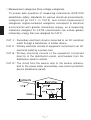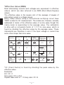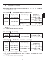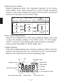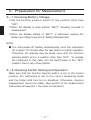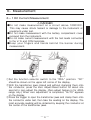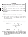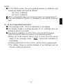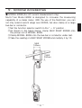
1
INSTRUCTION MANUAL 取扱説明書 DIGITAL CLAMP METER デジタルAC/DCクランプメータ KEW SNAP SERIES KEW SNAP 2009R Contents 1.Safety Warnings ・・・・・・・・・・・・・・・・・・・・・・・・・・・・・・・・・・・・・・・・ 2.Features ・・・・・・・・・・・・・・・・・・・・・・・・・・・・・・・・・・・・・・・・・・・・・・・ 3.Specifications ・・・・・・・・・・・・・・・・・・・・・・・・・・・・・・・・・・・・・・・・・・ 4.Instrument Layout ・・・・・・・・・・・・・・・・・・・・・・・・・・・・・・・・・・・・・・・ 5.Preparation for Measurement ・・・・・・・・・・・・・・・・・・・・・・・・・・・・ 5−1 Checking Battery Voltage ・・・・・・・・・・・・・・・・・・・・・・・・・・ 5−2 Checking Switch Setting and Operation ・・・・・・・・・・・・・ 6.Measurement ・・・・・・・・・・・・・・・・・・・・・・・・・・・・・・・・・・・・・・・・・・・ 6−1 DC Current Measurement ・・・・・・・・・・・・・・・・・・・・・・・・・・ 6−2 AC Current Measurement ・・・・・・・・・・・・・・・・・・・・・・・・・・ 6−3 DC Voltage Measurement ・・・・・・・・・・・・・・・・・・・・・・・・・・ 6−4 AC Voltage Measurement ・・・・・・・・・・・・・・・・・・・・・・・・・・ 6−5 Resistance Measurement ・・・・・・・・・・・・・・・・・・・・・・・・・・ 6−6 Continuity Check ・・・・・・・・・・・・・・・・・・・・・・・・・・・・・・・・・・ 6−7 Frequency Measurement ・・・・・・・・・・・・・・・・・・・・・・・・・・・ 6−8 Peak Measurement ・・・・・・・・・・・・・・・・・・・・・・・・・・・・・・・・ 6−9 Average Measurement ・・・・・・・・・・・・・・・・・・・・・・・・・・・・・ 7.Other Functions ・・・・・・・・・・・・・・・・・・・・・・・・・・・・・・・・・・・・・・・・ 7−1 Auto-power-off Function ・・・・・・・・・・・・・・・・・・・・・・・・・・・・ 7−2 Data Hold Function ・・・・・・・・・・・・・・・・・・・・・・・・・・・・・・・・ 7−3 LoHz Function ・・・・・・・・・・・・・・・・・・・・・・・・・・・・・・・・・・・・ 7−4 OUTPUT Terminal ・・・・・・・・・・・・・・・・・・・・・・・・・・・・・・・・・ 8.Battery Replacement ・・・・・・・・・・・・・・・・・・・・・・・・・・・・・・・・・・・・ 9.Optional Accessories ・・・・・・・・・・・・・・・・・・・・・・・・・・・・・・・・・・・ 1 5 7 11 14 14 14 15 15 16 17 18 19 20 20 21 23 24 24 24 25 25 28 29 1. Safety Warnings ○This instrument has been designed and tested according to IEC Publication 61010: Safety Requirements for Electronic Measuring Apparatus. This instruction manual contains warnings and safety rules which must be observed by the user to ensure safe operation of the instrument and retain it in safe condition. Therefore, read through these operating instructions before starting using the instrument. WARNING ●Read through and understand instructions contained in this manual before starting using the instrument. ●Save and keep the manual handy to enable quick reference whenever necessary. ●Be sure to use the instrument only in its intended applications and to follow measurement procedures described in the manual. ●Be sure to understand and follow all safety instructions contained in the manual. Failure to follow the above instructions may cause injury, instrument damage and/or damage to equipment under test. ○The symbol indicated on the instrument means that the user must refer to related parts in the manual for safe operation of the instrument. Be sure to carefully read the instructions following each symbol in this manual. DANGER is reserved for conditions and actions that are likely to cause serious or fatal injury. WARNING is reserved for conditions and actions that can cause serious or fatal injury. CAUTION is reserved for conditions and actions that can cause minor injury or instrument damage. ̶ 1 ̶ Following symbols are used on the instrument and in the instruction manual. Attention should be paid to each symbol to ensure your safety. # Refer to the instructions in the manual. This symbol is marked where the user must refer to the instruction manual so as not to cause personal injury or instrument damage. Indicates an instrument with double or reinforced insulation. Indicates that this instrument can clamp on bare conductors when measuring a voltage corresponding to the applicable Measurement category, which is marked next to this symbol. Indicates AC (Alternating Current). Indicates DC (Direct Current). Indicates AC and DC. This instrument satisfies the marking requirement defined in the WEEE Directive. This symbol indicates separate collection for electrical and electronic equipment. DANGER ●Never make measurement on a circuit above 750VAC/1000VDC. ●Do not attempt to make measurement in the presence of flammable gasses, fumes, vapor or dust. Otherwise, the use of the instrument may cause sparking, which can lead to an explosion. ●Never attempt to use the instrument if its surface or your hand is wet. ●Do not exceed the maximum allowable input of any measurement range. ●Never open the battery compartment cover when making measurement. ●Never try to make measurement if any abnormal conditions, such as broken Transformer jaws or case is noted. ●The instrument is to be used only in its intended applications or conditions. Otherwise, safety functions equipped with the instrument doesn't work, and instrument damage or serious personal injury may be caused. ̶ 2 ̶ WARNING ●Never attempt to make any measurement, if the instrument has any structural abnormality such as cracked case and exposed metal part. ●Do not turn the function selector switch with plugged in test leads connected to the circuit under test. ●Do not install substitute parts or make any modification to the instrument. Return the instrument to Kyoritsu or your distributor for repair or re-calibration. ●Do not try to replace the battery if the surface of the instrument is wet. ●Always switch off the instrument before opening the battery compartment cover for battery replacement. CAUTION ●Make sure that the function selector switch is set to an appropriate position before making measurement. ●Always make sure to insert each plug of the test leads fully into the appropriate terminal on the instrument. ●Make sure to remove the test leads from the instrument before making current measurement. ●Do not expose the instrument to the direct sun, extreme temperatures or dew fall. ●Be sure to set the function selector switch to the“OFF" position after use. When the instrument will not be in use for a long period of time, place it in storage after removing the battery. ●Use a damp cloth and detergent for cleaning the instrument. Do not use abrasives or solvents. ̶ 3 ̶ ○Measurement categories (Over-voltage categories) To ensure safe operation of measuring instruments, IEC61010 establishes safety standards for various electrical environments, categorized as CATⅠ to CATⅣ, and called measurement categories. Higher-numbered categories correspond to electrical environments with greater momentary energy, so a measuring instrument designed for CATⅢ environments can endure greater momentary energy than one designed for CATⅡ. CAT Ⅰ : Secondary electrical circuits connected to an AC electrical outlet through a transformer or similar device. CAT Ⅱ : Primary electrical circuits of equipment connected to an AC electrical outlet by a power cord. CAT Ⅲ : Primary electrical circuits of the equipment connected directly to the distribution panel, and feeders from the distribution panel to outlets. CAT Ⅳ : The circuit from the service drop to the service entrance, and to the power meter and primary over-current protection device (distribution panel). ̶ 4 ̶ 2.Features ●Tear-drop-shaped jaws for ease of use in crowded cable areas and other tight places. ●Accurate true-RMS reading of AC current or voltage with distorted waveform. ●Average function for easy reading of input with large variation. ●Auto-null function for easy zero adjustment. ●Provides frequency reading in AC current or voltage measurement. ●Auto-ranging feature on current, voltage and resistance ranges. ●Wide measuring range from 0 up to 2000A. ●Terminal cover to avoid the use of an incorrect terminal. ●PEAK function for measuring a peak of input ●Provides recorder output for long hour monitoring ●Data Hold function for easy reading in dimly light or hard-to-read locations ●Auto-power-off feature to extend battery life. ●Permits easy continuity check with a beeper ●Provides a dynamic range of 4200 counts full scale ●Wide frequency range from 20Hz to 1kHz ●Uses shrouded transformer jaws to further improve safety ●Designed to CAT.Ⅳ 600VAC,DC / CAT.Ⅲ750VAC,1000VDC p o l l u t i o n d e g r e e2 s p e c i f i e d b y t h e i n t e r n a t i o n a l s a f e t y standard:IEC61010. ̶ 5 ̶ *Effective Value (RMS) Most alternating currents and voltages are expressed in effective values, which are also referred to as RMS (Root-Mean-Square) values. The effective value is the square root of the average of square of alternating current or voltage values. Many clamp meters using a conventional rectifying circuit have "RMS" scales for AC measurement. The scales are, however, actually calibrated in terms of the effective value of a sine wave though the clamp meter is responding to the average value. The calibration is done with a conversion factor of 1.111 for sine wave, which is found by dividing the effective value by the average value. These instruments are therefore in error if the input voltage or current has some other shape than sine wave. Waveform A 0 A 0 Effective value Average value Conversion Reading errors for Crest factor factor average sensing Vrms Vavg CF Vrms/ Vavg instrument 1 2 π A A 2 π 0% 2 2 2 ≒1.414 ≒0.707 ≒0.637 ≒1.111 A×1,111-A ×100 A A 1 1 A =11.1% A 0 A 0 1 A 3 T A f D 0.5A 2 3 ≒1.155 0.5A×1.111A 3 A 3 ×100 =-3.8% 3 ≒1.732 1 (1.111 1 f D -1) A A T =A・D A D = = D D A D ×100% AD D=f/T *CF (Crest Factor) is found by dividing the peak value by the effective value. Examples: DC: CF =1 Sine wave: CF=1.414 Square wave with a 1: 10 duty ratio: CF=3 ̶ 6 ̶ 3.Specifications ●Measuring Ranges and Accuracy (at 23 ℃ ± 5 ℃ , relative humidity75% or less) AC Current (RMS value detection, Auto-range) Range Display range 400A 0.0∼420.0A 2000A 150∼2100A Accuracy※ (Frequency) ±1.3%rdg±3dgt (45∼66Hz) 0.0∼1700Arms ±2.0%rdg±5dgt (20Hz∼1kHz) 1700∼2000Arms ±2.3%rdg±3dgt (3000Apeak or less) (45∼66Hz) Allowable input ※For non-sinusoidal waveforms, add ±(1.5% of full scale), for Crest factor<3. ※4 counts or less is corrected to 0 DC Current Range 400A 2000A AC Voltage Range , Auto-range Display range ±0.0∼420.0A ±150∼2100A Allowable input 0.0∼±2000A Accuracy ±1.3%rdg±2dgt After zero adjustments (RMS value detection, Auto-range) Display range 40V 0.00∼42.00V 400V 15.0∼420.0V 750V 150∼788V Accuracy※ (Frequency) ±1.0%rdg±2dgt 0.00∼750Vrms (45∼66Hz) (1200Vpeak or less) ±1.5%rdg±5dgt (20Hz∼1kHz) Allowable input ※Input Impedance:approx. 2MΩ <200pF ※For non-sinusoidal waveforms, add ±(1.5% of full scale), for Crest factor<3. ※4 counts or less is corrected to 0 ̶ 7 ̶ DC Voltage Range (Auto-range) Display range 40V 0.00∼±42.00V 400V ±15.0∼±420.0V 1000V ±150∼±1050V Allowable input Accuracy 0.00∼±1000V ±1.0%rdg±2dgt ※Input Impedance:approx. 2MΩ Resistance / Continuity Range Display range 400Ω 0.0 ∼ 420.0Ω 4000Ω 150 ∼ 4200Ω (Auto-range) Allowable input Accuracy 0.0Ω∼ 4000Ω ±1.5%rdg±2dgt ※Open-loop Voltage:approx.3V, Measuring Current : 0.6mA or less (400Ωrange) 0.06mA or less(4000Ωrange) ※The buzzer turns on for resistances lower than 20±1Ω. Frequency Hz ( AC Current) (Auto-range) Range Display range 1000Hz 8.0 ∼ 999.9Hz 4000Hz 900 ∼ 4200Hz Allowable input Accuracy 10.0Hz ∼ 1000Hz ±1.5%rdg±5dgt 1000 ∼ 4000Hz ±1.5%rdg±5dgt Frequency Hz(AC Voltage) (Auto-range) Range Display range 1000Hz 8.0 ∼ 999.9Hz 4000Hz 900 ∼ 4200Hz Allowable input Accuracy 10.0Hz ∼ 1000Hz ±1.5%rdg±5dgt 900 ∼ 4000Hz ̶ 8 ̶ ±1.5%rdg±5dgt Output Output voltage: 0.1mV / 1count Range DC400A Allowable input Output Voltage (mVDC) 0.0∼±400.0A 0∼±400mV DC2000A 0∼±2000A 0∼±200mV AC400A 0.0∼400.0A 0∼400mV AC2000A 0∼2000A 0∼200mV Accuracy Within ±1mV (To the indicated value) ※When the display is "OL", the output voltage is 420mV("-OL": -420mV) ※Output impedance: about 10kΩ Note:◇The symbol of "―" in the above table means that the instrument only displays the value, but the accuracy, the proper operation and the safety are not guaranteed. ̶ 9 ̶ ●Operating System ●Display ●Overrange Indication ●Response Time ●Sample Rate ●Location for use ●Temperature and Humidity for Guranteed Accuracy ●Operating Temperature and Humidity ●Storage Temperature and Humidity ●Power Source ●Current Consumption ●Auto-power-off function ●Overload Protection ●Withstand Voltage ●Insulation Resistance ●Conductor Size ●Dimensions ●Weight ●Accessories ●Optional Accessories ΔΣ modulation Liquid crystal display with a maximum count of 4200 plus annunciators "OL" is shown on the display Approx. 2 seconds. About 3 times per second. Indoor use, Altitude up to 2000m 23 +/-5℃ , relative humidity up to 75% without condensation 0-40℃ , relative humidity up to 85% without condensation -20-60℃ , relative humidity up to 85% without condensation Two 1.5VDC R6P (SUM-3) batteries Approx. 40mA max (ACA). Automatically powered down in about 10 minutes after the last switch operation (power consumption: about 200μA) DC/AC current ranges: 2400A AC for 10sec DC/AC voltage ranges: 1200V AC/DC for 10sec Resistance range: 1000V AC/DC for 10sec 6880V AC, 50/60Hz for 5 seconds between electrical circuit and housing case or metal part of the jaws 10MΩ or greater at 1000V between electrical circuit and housing case or metal part of the jaws Approx. 55㎜ diameter max. 250(L)x105(W)x49(D)mm About 540g Test leads M-7017 R6P battery Carrying case M-9094 Instruction manual Recorder output Plug M-8201 Multi-Tran M-8008 Output Lead M-7014. ̶ 10 ̶ 4.Instrument Layout ① ⑮ ② ③ ④ ⑭ ⑦ ⑤ ⑥ ⑫ ⑨ ⑧ ⑩ ⑪ ⑬ ①Transformer Jaws Pick up current flowing through the conductor. ②Jaw Trigger Operates the transformer jaws. Press to open the Transformer Jaws. ③Function Selector Switch Selects function. Also used to power the instrument on. ④Data Hold Button Freezes the display reading. "H" is shown on the display when Data Hold is enabled. When the plug is inserted into the output terminal, Data Hold Switch operates as range selection switch.(See 7-4 output terminal) ̶ 11 ̶ ⑤Mode Selector Button Selects measuring mode. The instrument defaults to the normal mode (NOR). Then, press this switch to cycle through measuring modes. In any mode, pressing this switch for more than one second returns the instrument to the normal mode. A /V A /V ACA/ACV Display DCA/DCV Normal Normal Average Resistance Ω Average Peak Frequency Ω Resistance Display Continuity Display Continuity check Peak Hz ⑥Zero Adjust/Reset Button Used for zero adjustment on DCA and resistance ranges. Also used to reset the display reading in the PEAK mode. On DCA range, "AUTO" is shown on the display when auto-zeroing is completed. (Auto-zeroing is available on 400A range only.) ⑦Digital Display Field effect digital display with maximum reading of 4200. Function symbols and decimal point are controlled by the microprocessor based on the selected function and measuring mode. AC DC Average mode Data Hold Negative sign Resistance Voltage Continuity check Low battery warning Ampere Low frequency input Peak mode ̶ 12 ̶ DCA auto zero ⑧Terminal Cover Slides over V/Ω and COM Terminals to prevent access to them when OUTPUT terminal is in use. ⑨OUTPUT Terminal(For AC or DC current range only) Provides DC voltage output in proportion to the AC or DC current reading. The output is connected to a recording device such as a chart recorder for long hour monitoring. No output is available on voltage and resistance ranges. ⑩COM Terminal Accepts the black test lead for voltage or resistance measurement. ⑪V/Ω Terminal Accepts the red test lead for voltage or resistance measurement. ⑫Safety Hand Strap Prevents the instrument from slipping off the hand during use. ⑬ Test Leads (Model 7107) Connected to COM and V/Ω terminals for voltage or resistance measurement. ⑭Output Plug(Model 8201) Plugs into the OUTPUT terminal for connection to a recording device. (See section 7 ー 4, OUTPUT Terminal.) ⑮Barrier It is a part providing protection against electrical shock and ensuring the minimum required air and creepage distances. ̶ 13 ̶ 5.Preparation for Measurement 5-1 Checking Battery Voltage ①Set the function selector switch to any position other than "OFF". ②When the display is clear without "BATT" showing, proceed to measurement. ③When the display blanks or "BATT" is indicated, replace the battery according to section 8. Battery Replacement. NOTE ● The Auto-power-off feature automatically turns the instrument off in about 10 minutes after the last switch or button operation. Therefore, the display may be blank even with the function selector switch set to a position other than "OFF". To operate the instrument in this case, turn the switch back to the "OFF" position, then to any other position. 5-2 Checking Switch Setting and Operation Make sure that the function selector switch is set to the correct position, the instrument is set to the correct measuring mode and the Data Hold function is disabled. Otherwise, desired measurement cannot be made. (See section 6 for measurement instructions and section 7 for notes on functions.) ̶ 14 ̶ 6.Measurement 6-1 DC Current Measurement DANGER ●Do not make measurement on a circuit above 1000VDC. This may cause shock hazard or damage to the instrument or equipment under test. ●Do not make measurement with the battery compartment cover removed from the instrument. ●Do not make current measurement with the test leads connected to the V/Ω and COM terminals. ●Keep your fingers and hands behind the barrier during measurement. Correct Wrong ①Set the function selector switch to the " A" position.“DC" should be shown on the upper left corner of the display. ②With the transformer jaws closed and without clamping them onto the conductor, press the Zero Adjust/Reset button for about one second to zero adjust the display. (Zero adjust feature is for 400A range only.) When zero adjustment is completed, "AUTO" appears on the display. ③Press the trigger to open the transformer jaws and clamp them onto the conductor under test, then take the reading on the display. The most accurate reading will be obtained by keeping the conductor at the center of the transformer jaws. ̶ 15 ̶ NOTE ● During current measurement, keep the transformer jaws fully closed. Otherwise, accurate measurement cannot be made. The maximum measurable conductor size is approx. 55mm in diameter. ● When the current flows from the upside (the display side) to the underside of the instrument, the reading is indicated positive. ● The Zero Adjust/Reset button may not completely zero adjust the output voltage from the OUTPUT terminal. In this case, make zero adjustment on the recording device. ● Turing the function selector switch to a position other than DCA cancels the zero adjustment. 6-2 AC Current Measurement DANGER ●Never use the instrument on a circuit above 750VAC. This may cause electrical shock hazard and damage to the instrument or the circuit under test. ●Do not make measurement with the test leads plugged into the instrument. ●Do not make measurement with the battery compartment cover removed. ●Keep your fingers and hands behind the barrier during measurement. Correct Wrong ̶ 16 ̶ ①Set the function selector switch to the " ∼ A" position.“AC" should be shown on the upper left corner of the display. ②Press the trigger to open the transformer jaws and clamp them onto a single conductor and take the reading on the display. The most accurate reading will be obtained by keeping the conductor at the center of the transformer jaws. NOTE ● During current measurement, keep the transformer jaws fully closed. Otherwise, accurate measurements cannot be taken. Maximum conductor size is 55㎜ in diameter. ● Zero adjustment is not necessary in AC current measurement. ● When the current under test measures 3% of the range or less, or the frequency of the current is low, "LoHz" is indicated on the display. 6-3 DC Voltage Measurement DANGER ●Never use the instrument on a circuit above 1000VDC. This may cause electrical shock hazard and damage to the instrument or the circuit under test. ●Do not make measurement with the battery compartment cover removed. ●Keep your fingers and hands behind the barrier during measurement. Red test lead Black test lead ̶ 17 ̶ ①Set the function selector switch to the "V" position.“DC" should be shown on the upper left corner of the display. ②Slide the terminal cover to the left to disclose the V/Ω and COM terminals. Plug the red test lead into the V/Ω terminal and the black test lead into COM terminal. ③Connect the tip of the red and black test leads to the positive (+) and negative (-) sides of the circuit under test respectively. Take the reading on the display. If the connection is reversed, the display indicates the "-" sign. 6-4 AC Voltage Measurements DANGER ●Never use the instrument on a circuit above 750VAC. This may cause electrical shock hazard and damage to the instrument or the circuit under test. ●Do not make measurement with the battery compartment cover removed. ●Keep your fingers and hands behind the barrier during measurement. Red test lead Black test lead ①Set the function selector switch to the " ∼ V" position. "AC" should be shown on the upper left corner of the display. ②Slide the terminal cover to the left to disclose the V/Ω and COM terminals. Plug the red test lead into V/Ω terminal and the black test lead into the COM terminal. ̶ 18 ̶ ③Connect the tip of the red and black test leads to the circuit under test and take the reading on the display. NOTE ● When the voltage under test measures 3% of the range or less, or the frequency of the voltage is low, "LoHz" is indicated on the display. 6-5 Resistance Measurement DANGER ●Never use the instrument on an energized circuit. ●Do not make measurement with the battery compartment cover removed. ●Keep your fingers and hands behind the barrier during measurement. Ω" position. ①Set the function selector switch to the " ②Slide the terminal cover to the left to disclose the V/Ω and COM terminals. Plug the red test lead into the V/Ω terminal and the black test lead into the COM terminal. ③With the tip of the test leads shorted together, press the Zero Adjust/Reset button to offset the resistance of the test leads. ④Connect the tip of the test leads to the circuit under test and take the reading on the display. ̶ 19 ̶ 6-6 Continuity Check (400Ω range fixed) ※The continuity check mode is enabled by pressing the mode " is indicated on the selector switch on resistance range. " display to show the instrument in the continuity check mode. The buzzer beeps, if the resistance under test is 20.0Ω or less. DANGER ●Never use the instrument on an energized circuit. ●Do not make measurement with the battery compartment cover removed. ●Keep your fingers and hands behind the barrier during measurement. ①Set the function selector switch to the " Ω" position. ②Slide the terminal cover to the left to disclose the V/Ω and COM terminals. Plug the red test lead into the V/Ω terminal and the black test lead into the COM terminal. ③With the tip of the test leads shorted together, press the Zero Adjust/Reset button to offset the resistance of the test leads. ④Press the mode selector button once to enter from the normal mode to the continuity check mode. " " should be indicated on the display. ⑤Connect the tip of the test leads to the circuit under test. If the resistance is 20.0Ω or less, the buzzer beeps. 6-7 Frequency Measurement ●On ACA or ACV range, the frequency of the current or voltage under test can be counted and shown on the display. ●In the frequency measurement mode, "Hz" is indicated on the display. ●Trigger threshold is approx. 10V for AC voltage and approx. 40A for AC current. ̶ 20 ̶ DANGER ●Never use the instrument on a high voltage circuit above 750VAC. This may cause electrical shock hazard and damage to the instrument or the circuit under test. ●Do not make measurement with the battery compartment cover removed. ●Do not make current measurement with the test leads plugged into the instrument. ●Keep your fingers and hands behind the barrier during measurement. ①Set the function selector switch to the " ∼ A" or " ∼ V" position. ②Press the mode selector button three times to enter from the normal mode to the frequency measurement mode. "Hz" should be indicated on the display. ③Follow instructions for ACA or ACV measurement and take the frequency reading. NOTE ● When the voltage under test measures 3% of the range or less, or the frequency of the current or voltage is 40Hz or less, "LoHz" is indicated on the display. 6-8 Peak Measurement ●In the PEAK mode, the display shows current or voltage's crest in effective value. (For example, when the current or voltage is sinusoidal, the reading equals the crest value divided by the square root of two.) The display reading is constantly updated with a maximum crest. ●In this mode, "PEAK" is indicated on the display. ●Response time is 300ms in DC measurement and 10ms in AC measurement. ̶ 21 ̶ DANGER ●Never use the instrument on a circuit above 750VAC/1000VDC. This may cause electrical shock hazard and damage to the instrument or the circuit under test. ●Do not make measurement with the battery compartment cover removed. ●Do not make measurement with the test leads plugged into the instrument. ●Keep your fingers and hands behind the barrier during measurement. ①The PEAK mode is available on DCA, ACA, DCV and ACV ranges. Set the function selector switch to the desired position. Note:Only on DCA range, press the Zero Adjust/Reset button for about one second to zero adjust the reading with the transformer jaws closed. ②Press the mode selector button twice to enter from the normal mode to the PEAK mode. "PEAK" should be shown on the display. ③Follow instructions for DCA, ACA, DCV or ACV measurement. INPUT Current Peak Hold Note:For accurate reading, press the Zero Adjust/Reset button to reset the reading after clamping onto the conductor or making test lead connections to the circuit under test. Then, proceed to measurement. ̶ 22 ̶ NOTE ● In the PEAK mode, the auto-ranging feature is disabled and measuring ranges are fixed as follows. DC/ACA: 0-400.0A DC/ACV: 0-400.0A ● When a measured value is 9 counts or less, it is corrected to 0 ● The Auto-power-off function is disabled in the PEAK mode as well. 6-9 Average Measurement ●In the Average mode, "AVG" is indicated on the display. ●The display reads a running average of six readings over an interval of about 2 seconds. ●This mode is available on ACV, DCV, ACA and DCA ranges. ①Set the function selector switch to the desired position. ②Press the mode selector button once to enter from the normal mode to the Average mode. " " should be indicated on the display. ③Follow instructions for ACV, DCV, ACA or DCA measurement. ④The display shows a running average of six readings over an interval of about 2 seconds. ̶ 23 ̶ 7.Other Functions 7-1 Auto-power-off Function CAUTION ●The instrument consumes small amount of battery power in the Auto-power-off mode. Make sure to set the function selector switch to the OFF position after use. This is a function to prevent the instrument from being left powered on in order to conserve battery life. This function causes the instrument to enter the Auto-power-off mode about 10 minutes after the last switch or button operation. To exit the Auto-power-off mode, turn the function selector switch back to "OFF", then to any other position, or press any button. NOTE ● Connecting the plug to the OUTPUT terminal disables the Autopower-off function. The function is enabled on removing the plug from the terminal. ● T h e A u t o - p o w e r - o f f f u n c t i o n i s d i s a b l e d i n t h e P E A K measurement mode. 7-2 Data Hold Function This is a function used to freeze the measured value on the display. Press the Data Hold button to freeze the reading. The reading will be held regardless of subsequent variation in input. " " is shown on the upper right corner of the display while the instrument is in the Data Hold mode. To exit the Data Hold mode, press the Data Hold button again. ̶ 24 ̶ NOTE ● If the instrument in the Data Hold mode goes into "Auto-poweroff," it will return to the normal mode. 7-3 LoHz Function In ACV or ACA range, if frequency of the voltage or current under test is 40Hz or lower, the display indicates "LoHz". "LoHz" is also indicated where input is 3% of range or less. 7-4 OUTPUT Terminal (For current ranges only) DANGER ●Never use the instrument on a circuit above 750VAC/1000VDC. This may cause electrical shock hazard and damage to the instrument or the circuit under test. ●Do not make measurement with the battery compartment cover removed. ●Never apply voltage to the OUTPUT terminal. ①Attach the output plug to a connection lead so that the output voltage can be connected to a recording device such as a chart recorder. ̶ 25 ̶ ②Slide the terminal cover to the right to disclose the OUTPUT terminal and insert the output plug into the terminal. Make connection to the recording device. ③When the plug is inserted into the output terminal, auto-range function is cleared. Set the range depending on the state of Data Hold Switch. Data Hold Switch OFF 400A range Data Hold Switch ON 2000A range Note:After measurement, be sure to return Data Hold Switch to OFF position. ④Set the function selector switch to the desired position (ACA or DCA) and follow appropriate measurement instructions. NOTE ● During current measurement, keep the transformer jaws fully closed. Otherwise, accurate measurement cannot be made. The maximum measurable conductor size is approx. 55mm in diameter. ● Zero adjustment is not necessary on AC current range. ● On DC current range, the Zero Adjust/Reset button may not completely zero adjust the output voltage from the OUTPUT terminal. In this case, make zero adjustment on the recording device. ● Connecting the plug to the OUTPUT terminal disables the Autopower-off function. The function is enabled on removing the plug from the terminal. ̶ 26 ̶ ● Consult the output voltage specifications shown in section 3 and adjust the sensitivity of the recording device. ● For long hours of use of the OUTPUT terminal, use an Alkaline battery, which will extend continuous recording time up to about 35 hours. ̶ 27 ̶ 8.Battery Replacement WARNING ●To avoid electric shock hazard, make sure to set the function selector switch to "OFF" and remove the test leads from the instrument before trying to replace battery. CAUTION ●Do not mix new and old battery. ●Make sure to install battery in correct polarity as indicated in the battery compartment. If the battery voltage becomes too low for the instrument to operate normally, " " is shown on the display. Then, replace the battery. Note that when the battery is completely exhausted, the display blanks without " " shown. ①Set the function selector switch to the "OFF" position. ②Unscrew and remove the battery compartment on the bottom of the instrument. ③Replace the battery observing correct polarity. Use a new R6P or equivalent battery. ④Re-place and screw the battery compartment cover. Screw Batteries ̶ 28 ̶ 9.Optional Accessories ● MODEL 8008 (For AC current measurement only) Multi-Tran Model 8008 is designed to increase the measuring capability of a clamp meter. With the use of the Multi-tran, you can not only extend current range over 3000A, but also clamp on a large bus-bar or conductor. ①Set the function selector switch to the " ∼ A" position . ②As shown in the figure below, clamp KEW SNAP 2009R onto the pickup coil of MODEL 8008. ③Clamp MODEL 8008 onto the bus-bar or conductor under test. ④Take the reading on KEW SNAP 2009R and multiply it by 10. MAX 100mm MAX 150mm ̶ 29 ̶ Memo ̶ 30 ̶ DISTRIBUTOR Kyoritsu reserves the rights to change specifications or designs described in this manual without notice and without obligations. 10-04 92-2022