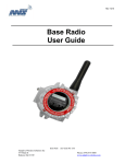
Download 1770-6.5.21, Smart Transmitter Toolkit, User Manual
Transcript
Smart Transmitter Toolkit User Manual Important User Information Because of the variety of uses for the products described in this publication, those responsible for the application and use of this control equipment must satisfy themselves that all necessary steps have been taken to assure that each application and use meets all performance and safety requirements, including any applicable laws, regulations, codes and standards. The illustrations, charts, sample programs and layout examples shown in this guide are intended solely for purposes of example. Since there are many variables and requirements associated with any particular installation, Allen-Bradley does not assume responsibility or liability (to include intellectual property liability) for actual use based upon the examples shown in this publication. Allen-Bradley publication SGI-1.1, Safety Guidelines for the Application, Installation, and Maintenance of Solid State Control (available from your local Allen-Bradley office), describes some important differences between solid-state equipment and electromechanical devices that should be taken into consideration when applying products such as those described in this publication. Reproduction of the contents of this copyrighted publication, in whole or in part, without written permission of Allen-Bradley Company, Inc., is prohibited. Throughout this manual we use notes to make you aware of safety considerations: ATTENTION: Identifies information about practices or circumstances that can lead to personal injury or death, property damage or economic loss. Attention statements help you to: identify a hazard avoid the hazard recognize the consequences Important: Identifies information that is critical for successful application and understanding of the product. Table of Contents Using This Manual . . . . . . . . . . . . . . . . . . . . . . . . . . . . . . . i What's In This Preface . . . . . . . . . . . . . . . . . . . . . . . . . . . . . . . . Purpose of This Manual . . . . . . . . . . . . . . . . . . . . . . . . . . . . . . . Who Should Use This Manual . . . . . . . . . . . . . . . . . . . . . . . . . . . How To Use This Manual . . . . . . . . . . . . . . . . . . . . . . . . . . . . . . Terms . . . . . . . . . . . . . . . . . . . . . . . . . . . . . . . . . . . . . . . . . . . . Abbreviations . . . . . . . . . . . . . . . . . . . . . . . . . . . . . . . . . . . . . . Conventions . . . . . . . . . . . . . . . . . . . . . . . . . . . . . . . . . . . . . . . Related Publications . . . . . . . . . . . . . . . . . . . . . . . . . . . . . . . . . . STT Software License . . . . . . . . . . . . . . . . . . . . . . . . . . . . . . . . i i i ii ii ii iii iii iii Introducing The Smart Transmitter Toolkit . . . . . . . . . . . . . 11 What's In This Chapter . . . . . . . . . . . . . . . . . . . . . . . . . . . . . . . . What's The Smart Transmitter Toolkit . . . . . . . . . . . . . . . . . . . . . . What You Get With The STT Subroutine . . . . . . . . . . . . . . . . . . . What You Need to Use The STT Subroutine . . . . . . . . . . . . . . . . . Why You Should Use The STT Subroutine . . . . . . . . . . . . . . . . . . How a PLC5 Processor Communicates With a HART Field Device How You Use The STT Subroutine . . . . . . . . . . . . . . . . . . . . . . . What to Do Next . . . . . . . . . . . . . . . . . . . . . . . . . . . . . . . . . . . . 11 11 12 13 13 14 16 16 Installing The Smart Transmitter Toolkit . . . . . . . . . . . . . . . 21 What's In This Chapter . . . . . . . . . . . . . . . . . . . . . . . . . . . . . . . . Before You Begin . . . . . . . . . . . . . . . . . . . . . . . . . . . . . . . . . . . . 1. Copy STT Subroutine File to the Hard Drive . . . . . . . . . . . . . . . 2. Create and Name a New Program File . . . . . . . . . . . . . . . . . . . 3. Paste The STT Subroutine File . . . . . . . . . . . . . . . . . . . . . . . . 4. Save Your Work (optional) . . . . . . . . . . . . . . . . . . . . . . . . . . . . 5. Change The STT Default Data File (optional) . . . . . . . . . . . . . . What's Next . . . . . . . . . . . . . . . . . . . . . . . . . . . . . . . . . . . . . . . . 21 21 22 23 24 25 26 26 Using The Smart Transmitter Toolkit . . . . . . . . . . . . . . . . . 31 What's In This Chapter . . . . . . . . . . . . . . . . . . . . . . . . . . . . . . . . 1. Create Data Table Files . . . . . . . . . . . . . . . . . . . . . . . . . . . . . . 2. Provide The STT Subroutine Inputs . . . . . . . . . . . . . . . . . . . . . 3. Use The STT Subroutine Status Word . . . . . . . . . . . . . . . . . . . 4. Call The STT Subroutine . . . . . . . . . . . . . . . . . . . . . . . . . . . . . 5. Interpret The STT Subroutine Outputs . . . . . . . . . . . . . . . . . . . Programming Example 1: Single HART Device With Single 1770HT1 . . . . . . . . . . . . . . . . . . . . . . . . . . . . . . 31 31 33 34 35 36 37 ii Table of Contents Programming Example 2: Multiple HART Devices With Single 1770HT1 . . . . . . . . . . . . . . . . . . . . . . . . . . . . . . Programming Example 3: Multiple HART Devices With Multiple 1770HT1s . . . . . . . . . . . . . . . . . . . . . . . . . . . . 313 HART Command Data Table Layouts . . . . . . . . . . . . . . . . . A1 What's In This Appendix . . . . . . . . . . . . . . . . . . . . . . . . . . . . . . . HART Command 0 Read HART Address . . . . . . . . . . . . . . . . . . . HART Command 0 Read HART Address . . . . . . . . . . . . . . . . . . . . . . . . . . . . . . . HART Command 1 Read Primary Variable . . . . . . . . . . . . . . . . . . . . . . . . . . . . . HART Command 3 Read Dynamic Variables & Primary Variable Current . . . . . . . . HART Command 3 Read Dynamic Variables & Primary Variable Current . . . . . . . . HART Command 35 Write Primary Variable Range Values . . . . . . . . . . . . . . . . . . . HART Command 35 Write Primary Variable Range Values . . . . . . . . . . . . . . . . . . . HART Command 38 Reset Configuration Change Flag . . . . . . . . . . . . . . . . . . . . . . HART Command 38 Reset Configuration Change Flag . . . . . . . . . . . . . . . . . . . . . . HART Command 43 Set Primary Variable Zero . . . . . . . . . . . . . . . . . . . . . . . . . . . HART Command 43 Set Primary Variable Zero . . . . . . . . . . . . . . . . . . . . . . . . . . . HART Command 44 Write Primary Variable Units . . . . . . . . . . . . . . . . . . . . . . . . . HART Command 44 Write Primary Variable Units . . . . . . . . . . . . . . . . . . . . . . . . . A1 A2 39 A3 A4 A6 A7 A8 A9 A10 A11 A12 A13 A14 A15 Codes . . . . . . . . . . . . . . . . . . . . . . . . . . . . . . . . . . . . . . . . B1 What's In This Appendix . . . . . . . . . . . . . . . . . . . . . . . . . . . . . . . STT Subroutine Error Codes . . . . . . . . . . . . . . . . . . . . . . . . . . . . Smart Transmitter Interface Error Codes . . . . . . . . . . . . . . . . . . . HART Protocol Communication Error Codes . . . . . . . . . . . . . . . . . Integer Word 34 . . . . . . . . . . . . . . . . . . . . . . . . . . . . . . . . . . . . . HART Command Response Summary Error Codes . . . . . . . . . . . Integer Word 35 . . . . . . . . . . . . . . . . . . . . . . . . . . . . . . . . . . . . . HART Field Device Error Codes . . . . . . . . . . . . . . . . . . . . . . . . . Unit Codes . . . . . . . . . . . . . . . . . . . . . . . . . . . . . . . . . . . . . . . . Integer Words 10 and 40 . . . . . . . . . . . . . . . . . . . . . . . . . . . . . . B1 B1 B2 B3 B3 B3 B3 B4 B5 B5 Preface Using This Manual What's In This Preface This preface describes how to properly and efficiently use this manual. Smart Transmitter Toolkit It tells you about: User Manual the purpose of this manual who should use this manual how to use this manual terms abbreviations conventions related publications publication 17706.5.21 Purpose of This Manual Use this manual to install and use the Smart Transmitter Toolkit. Throughout this manual we refer to this utility as the STT subroutine. Who Should Use This Manual This manual is intended for use by: persons who install Smart Transmitter Interface products, in connection with Allen-Bradley PLC controllers or other intelligent controllers system integrators who design and establish network systems that involve plant floor machinery, programmable controllers, HART field devices, Smart Transmitter Interface products, and host computers We assume that you have: a strong working knowledge of your plant’s process and equipment a familiarity with personal computers, MS-DOS or PC-DOS, ControlView, and 6200 programming software i Preface Using This Manual How To Use This Manual Start by reading about the STT subroutine. Then, follow the instructions in chapter 2 to install the STT subroutine. Finally, use chapter 3 and the appendices to help you incorporate the STT subroutine into your ladder logic. See HART Command Data Table Layouts appendix A Read about the STT subroutine chapter 1 Use the STT subroutine chapter 3 Install the STT subroutine chapter 2 See Codes appendix B Terms Some of the tasks described in this manual assume that you have an acquaintance with basic computer terminology. For a glossary of terms related to Smart Transmitter Interface products, see the Smart Transmitter Interface Products (HART Protocol) User Manual, publication 1770-6.5.19. Abbreviations ii In this manual, we use these abbreviations. This abbreviation: is for: BTR BTW HART JSR STT Blocktransfer Read Blocktransfer Write Highway Addressable Remote Transducer Jump to Subroutine Smart Transmitter Toolkit Preface Using This Manual Conventions We use these conventions in this manual: In this manual, we show: Like this: prompts and messages Press a function key literal text that you type STT_SUB variable text that you type filename keys that you press F1 screens that you see Program Directory that there is more information about the topic in another manual Related Publications AllenBradley Publications Publication Publication Number Smart Transmitter Interface Products (HART Protocol) User Manual 17706.5.19 PLC5 Programming Software Programming Manual 62006.4.7 For a list of publications for Allen-Bradley programmable controller products, see the Automation Group Publication Index, publication SD499. HART Publications STT Software License Publication Reference Number and Date HART - Smart Communications Protocol Specification Revision 5.1, January 4, 1991 Rosemount, Inc. Document No. D9000047, Revision A STT is not a licensed software product. It is provided to help you quickly communicate with HART field devices. Please feel free to use this software on any and all machines that you have. iii Chapter 1 Introducing The Smart Transmitter Toolkit What's In This Chapter This chapter gives you an overview of the Smart Transmitter Toolkit that you received with your Smart Transmitter Interface (cat. no. 1770-HT1). What's The Smart Transmitter Toolkit The Smart Transmitter Toolkit (STT) is a PLC-5 ladder logic subroutine utility that saves development time by simplifying the communication among Allen-Bradley PLC-5 processors, Allen-Bradley Smart Transmitter Interfaces, and HART-compliant field devices, such as a smart transmitter or actuator. ✔ The STT subroutine provides a shell that lets you use a PLC processor to communicate with a HART field device, without having detailed knowledge of the HART protocol. ✔ The STT subroutine supports the HART commands that are most commonly used with PLC processors. The STT subroutine does not support vendor-specific HART commands, such as totalization. ✔ STT focuses on digital data that is associated with the HART protocol. Use Allen-Bradley Analog I/O modules to acquire 4-20mA analog data. HART Universal Commands The functions performed by these commands are performed by all HART devices. HART Commonpractice Commands The functions performed by these commands may not be possible for all HART devices. HART Transmitterspecific Commands Only one or at most a few HART devices implement these functions. The functions performed by these commands allow each device type to implement their own commands for special functions, calibration, and special data handling. Refer to the product manual for your HART field device for a list of supported commands. ✔ STT does not include faceplates or operator interface screens. However, you can configure operator interface software, such as ControlView software, to display/modify data that is received/sent to the STT subroutine. ✔ STT supports: HART Universal Commands 0, 1, and 3 HART Common Practice Commands 35, 38, 43, and 44 Both long- and short-frame addressing Both point-to-point and multi-drop configurations Allen-Bradley PLC-5 processors Important: Do not view STT as a configuration tool. We assume you take the appropriate steps to configure and calibrate the HART field device using either Cornerstone software or a hand-held terminal. 1-1 Chapter 1 Introducing The Smart Transmitter Toolkit What You Get With The STT Subroutine The STT subroutine transfers this digital data between the PLC-5 processor and HART field devices: Read - primary variable and unit - primary variable current - dynamic variables and unit - status information Write/modify primary variable range values Write primary variable unit Reset configuration change flag Set primary variable to zero You Provide STT Provides 6200 Programming Software Workstation Data Highway Plus PLCresident Control Functions PLC5 ladder logic subroutine that simplifies the communication between a PLC5 processor and a HART field device. Your Application Program STT Data Tables and Subroutine Call PLC5 Processor Smart Transmitter Interface 1770HT1 RIO 1770HT16 HART Field Devices 4-20 mA Loop 1-2 Chapter 1 Introducing The Smart Transmitter Toolkit What You Need to Use The STT Subroutine You need these hardware and software components to integrate STT with your new or existing PLC-5 processor: Hardware (1 or more) 1770-HT1 Smart Communications Controller(s) (1 or more) 1770-HT8 or 177-HT16 Terminal Block(s) (1 or more) HART-compliant field device(s) Software PLC-5 6200 Programming Software (2 or more) PLC-5 data table files (1 or more ) PLC-5 programming file(s) PLC-5 integer data table file locations N90:0, N90:1, and N90:2 Why You Should Use The STT Subroutine The STT subroutine greatly simplifies sending and receiving data to and from HART field devices. Without STT, the ladder developer must: ✔ Format each command from the HART specification using the Smart Transmitter Interface protocol. ✔ Understand HART protocol internals, such as long frame addressing vs. short frame addressing, and byte swapping for word alignment. ✔ Parse HART command responses for data. ✔ Convert IEEE-754 data to floating-point data. ✔ Synchronize BTWs with BTRs. With STT, the ladder developer must only: ✔ Configure a data block. ✔ Make the appropriate call to the STT subroutine. 1-3 Chapter 1 Introducing The Smart Transmitter Toolkit How a PLC5 Processor Communicates With a HART Field Device PLC5 Processor To help explain what the STT subroutine can do for you, let’s examine how communication occurs between a PLC processor and a HART field device. ➊ The PLC-5 processor sends a Smart Transmitter Interface packet to the 1770-HT1 as block-transfer write (BTW) data. ➋ The 1770-HT1 forwards the Smart Transmitter Interface packet as a HART packet to the HART field device. ❸ The HART field device receives the HART packet and then responds back to the 1770-HT1 with a HART packet that contains the appropriate HART digital data. ➍ The 1770-HT1 routes the response back to the PLC-5 processor in a Smart Transmitter Interface packet as block-transfer read (BTR) data. Smart Transmitter Interface ➊ BTW Data Smart Transmitter Interface packet HART Field Device 1770HT1 RIO ➍ BTR Data 1770HT16 ➋ HART Poll HART packet 420 mA Loop ❸ HART Response 90065 1-4 Chapter 1 Introducing The Smart Transmitter Toolkit The PLC-5 processor sends and receives data from the 1770-HT1 as Smart Transmitter Interface Packets. The HART field device sends and receives data from the 1770-HT1 as HART packets. The 1770-HT1 converts the packets that it receives to the required format before transmitting the packets to their destination. This diagram illustrates the relationship between the two packets. Smart Transmitter Interface packet Smart Transmitter Interface Command Channel Number Control Parameter HART packet Preamble Delimiter Address HART Command Byte Count Data Check Byte 90066 Using a few pieces of data, the STT subroutine creates a Smart Transmitter Interface packet and sends it to the 1770-HT1. The STT subroutine then takes the response from the 1770-HT1 and decodes the Smart Transmitter Interface packet to provide you with useful data. For more information about communications with Smart Transmitter Interface products, see the Smart Transmitter Interface Products (HART Protocol) User Manual, publication 1770-6.5.19. 1-5 Chapter 1 Introducing The Smart Transmitter Toolkit How You Use The STT Subroutine We developed the STT Subroutine so that you can easily use a PLC-5 processor to communicate with a HART field device. Here’s how easy it is to use STT: 1. Read Chapter chapter 2, 2 then Installing install theThe software. Smart Transmitter Toolkit STT Subroutine 2. Chapter 3 Using The Smart Transmitter Toolkit Install the STT subroutine into your workstation and PLC-5 processor. Customize your PLC-5 ladder logic to use the STT subroutine. a. Allocate data blocks in your PLC5 processor for each HART field device in your system. b. Enter a JSR instruction in your ladder logic program for each 1770HT1 in your system. When you’ve completed these steps, you’re ready to use the STT subroutine. What to Do Next 1-6 Go to chapter 2 to begin installing the Smart Transmitter Toolkit. Chapter 2 Installing The Smart Transmitter Toolkit What's In This Chapter This chapter provides instructions for installing the Smart Transmitter Toolkit (STT). Important: Use 6200 programming software to install the STT subroutine into your PLC-5 processor. Before you begin, make sure your current program is loaded. To install the STT subroutine, you will: 1. Copy the STT subroutine file to the hard drive. 2. Create and name a new program file in your PLC-5 processor. 3. Paste the STT subroutine file into the new program file. 4. Save your work (optional). 5. Change the data table defaults (optional) Important: The STT subroutine uses three fixed word addresses: N90:0 through N90:2. When you paste the STT subroutine, these three addresses are created. If these addresses are already in use and cannot be freed up for the STT Subroutine, you need to change the data table defaults. If you need to make these changes, do step 5. The rest of this chapter contains the instructions for completing these steps. Before You Begin You need this diskette to install the STT subroutine: Allen-Bradley Software Smart Transmitter Toolkit Disk 1 of 1 This diskette contains these paste files: • STT100.CR5 - the STT subroutine • STT100E1.CR5 - programming example 1 • STT100E2.CR5 - programming example 2 • STT100E3.CR5 - programming example 3 See chapter 3 for an explanation of the programming examples. Since you install the STT subroutine using 6200 programming software, you may want to obtain a copy of the PLC-5 Programming Software Programming Manual, publication 6200-6.4.7. 2-1 Chapter 2 Installing The Smart Transmitter Toolkit 1. Copy STT Subroutine File to the Hard Drive A. Insert the STT disk into a floppy drive. B. Start at the 6200 Main Menu and press these keys: File Utils 6200 Main Menu F7 To/From Floppy From Floppy F9 F2 Processor Memory: Cut Rungs F7 You see: C. Use the cursor keys to highlight the STT100 file. D. To select the STT100 file as the source of the copy, press F3 Select Source. E. To begin the copy, press F1 Begin Oper. The operation is completed. F. 2-2 To return to the 6200 Main Menu, press Esc Esc . Chapter 2 Installing The Smart Transmitter Toolkit 2. Create and Name a New Program File A. Start at the 6200 Main Menu and press these keys: 6200 Main Menu Online Prog F1 Offline Prog or Proc Func F3 F1 You see: B. To create a program file, press file number. C. To name the file, press F10 F6 Create Lad Fl Change Fl Name and then enter a and then enter a file name. We recommend that you use the filename STT_SUB. D. To go to the Program Directory, press Esc . 2-3 Chapter 2 Installing The Smart Transmitter Toolkit 3. Paste The STT Subroutine File A. Start at the Program Directory and press these keys: Program Directory Monitor File Edit Advanced Edit F8 F10 F8 Paste From Disk F8 You see: B. Use the cursor keys to highlight the STT100 file. C. To begin the paste, press F1 Begin Paste. The paste operation takes about 3 minutes. Since the STT subroutine uses indirect addressing, you may hear beeps during the paste operation. This is normal. D. 2-4 To return to the Program Directory, press Esc Esc . Chapter 2 Installing The Smart Transmitter Toolkit 4. Save Your Work (optional) A. Start at the Program Directory and press these keys: Program Directory Save Restore Save Program F2 F2 You see: B. If you want to change the name of the file, enter a new name. If you don’t enter a new name, the file is saved using the name that you see on the screen. C. To save the file, press F1 Begin Oper. 2-5 Chapter 2 Installing The Smart Transmitter Toolkit 5. Change The STT Default Data File (optional) You can move the STT subroutine data table file from its default location of N90. Important: Moving this file increases the chance of making errors while setting up your system and complicates the technical support of the STT subroutine because the file is not in its default location. We recommend that you only attempt this procedure if you are experienced in ladder-logic programming and using 6200 programming software. The STT subroutine uses indirect addresses in block-transfer instructions. You cannot use 6200 programming software to edit/cut/copy/paste block-transfer instructions that use indirect addressing or to search for file references that use indirect addressing. To move the file, follow these steps: A. Use the 6200 file utilities to export the processor memory file and comments/symbols. Make sure that you export all the different types of comments (address, rung, instruction, etc.). The exported program file has a .PC5 extension. The exported comments/symbols file has a .TXT extension. For more information about using 6200 file utilities, see PLC-5 Programming Software Programming Manual, publication 6200-6.4.7. B. Use an ASCII text editor to make the changes as described below. Moving the STT Data Table File From N90 a. Edit the .PC5 file b. Search for all occurrences of integer file number N90 and change to the new integer file number. c. Save the changes and close the file. d. Edit the .TXT file. e. Search for all occurrences of integer file number N90 and change to the new integer file number. f. C. What's Next 2-6 Save the changes and close the file. Import the modified processor memory file and comments/symbols file. Use a different name for the imported files to distinguish them from the original files. You are finished installing the STT subroutine. Proceed to the next chapter for instructions on using the STT subroutine in your ladder logic. Chapter 3 Using The Smart Transmitter Toolkit What's In This Chapter Follow the instructions in this chapter to incorporate the STT subroutine into your ladder code and use the HART commands. 1. Create data table files. 2. Provide the STT subroutine inputs 3. Use the STT subroutine status word. 4. Call the STT subroutine. 5. Interpret the STT subroutine outputs. At the end of this chapter, you’ll find some programming examples. 1. Create Data Table Files Integer word = 16 bits Floatingpoint word = 32bits In your PLC-5 processor, create one integer and one floating-point file for each HART field device. Each integer file must be 150 integer words minimum (0 through 149) Each floating-point file must be 20 floating-point words minimum (0 through 19) In addition, the floating point file must be the data file that immediately follows the integer data file. For example, if the integer file is N10, the floating point file must be F11. Important: The STT utility uses integer data file N90 for indirect addressing. Do not use this data file for a HART field device data table file. Since the STT subroutine uses N90:0 and N90:1 for indirect addressing, you must place valid file numbers in N90:0 and N90:1. For example, if you created N10 and F11, you need to place a 10 in data table location N90:0 and an 11 in data table location N90:1. Following is an explanation of how the data tables are used by the STT subroutine. 3-1 Chapter 3 Using The Smart Tranmsitter Toolkit Example of Newly Created Integer Data File Data Table Report Address N10:0 N10:10 N10:20 N10:30 N10:40 N10:50 N10:60 N10:70 N10:80 N10:90 N10:100 N10:110 N10:120 N10:130 N10:140 PLC–5/25 0 0 0 0 0 0 0 0 0 0 0 0 0 0 0 0 1 0 0 0 0 0 0 0 0 0 0 0 0 0 0 0 2 0 0 0 0 0 0 0 0 0 0 0 0 0 0 0 3 0 0 0 0 0 0 0 0 0 0 0 0 0 0 0 Addr 31 Data Table File N10:0 4 0 0 0 0 0 0 0 0 0 0 0 0 0 0 0 5 0 0 0 0 0 0 0 0 0 0 0 0 0 0 0 6 0 0 0 0 0 0 0 0 0 0 0 0 0 0 0 7 0 0 0 0 0 0 0 0 0 0 0 0 0 0 0 8 0 0 0 0 0 0 0 0 0 0 0 0 0 0 0 9 0 0 0 0 0 0 0 0 0 0 0 0 0 0 0 Integer words 60 through 149 = STT Subroutine Work Area Integer words 30 through 59 = STT Subroutine Status and Output Area Integer words 0 through 29 = User Input Area Example of Newly Created Floatingpoint Data File Data Table Report Address F11:0 F11:5 F11:10 F11:15 PLC–5/25 0 0 0 0 0 1 0 0 0 0 Floatingpoint words 10 through 19 = STT Subroutine Output Area Floatingpoint words 0 through 9 = User Input Area 3-2 Addr 31 2 0 0 0 0 Data Table File F11:0 3 0 0 0 0 4 0 0 0 0 Chapter 3 Using The Smart Transmitter Toolkit 2. Provide The STT Subroutine Inputs All data that is used by the STT subroutine is obtained from the integer and floating point data files that you create for each HART field device. Before you make a call in your ladder logic to the STT, you must put the required data into these data files. There are two types of input data: Command-specific inputs are specific for each HART command. See appendix A. Standard inputs are required for every HART command. This table explains each of the six standard inputs. Standard Inputs Integer Word 0 I/O Rack Number of 1770HT1 I/O Group Number of 1770HT1 Channel Number of HART field device Polling Address of HART field device This integer word contains the I/O rack number of the 1770-HT1 that is connected to the HART field device. Valid values are 1 through 7. This integer word contains the I/O group number of the 1770-HT1 that is connected to the HART field device. Valid values are 0, 2, 4, and 6. This integer word contains the channel on the 1770-HT8 or the 1770-HT16 that is wired to the HART field device. Valid values are 1 through 32. This integer word contains the polling address of the HART field device. Use a Rosemount 268 Handheld terminal or Cornerstone software to configure this address. Word 4 Smart Transmitter Interface Command Number 16 decimal (10 Hex) If you are wired: • pointtopoint, the polling address is 0 (zero). • multidrop, the polling address is 1 through 15. Note: Most HART field devices come from the factory with a default polling address of zero. This integer word contains the number of the Smart Transmitter Interface command. Currently, the only supported command is 16. This command indicates that you want to send a HART command to a HART field device. Always place a 16 in word 4 of the integer data file. Word 5 HART Command Word 1 Word 2 Word 3 This integer word contains the number of the HART command that the STT subroutine generates and processes. Valid values are 0, 1, 3, 35, 38, 43, and 44. Every HART command, except 0, requires the HART address returned by HART command 0. Example: Inputs for HART Command 0 Data Table Report Address N10:0 N10:10 N10:20 N10:30 N10:40 N10:50 • • • • • • 0 4 0 0 0 0 0 PLC–5/25 1 6 0 0 0 0 0 2 3 0 0 0 0 0 3 0 0 0 0 0 0 Addr 31 4 16 0 0 0 0 0 Data Table File N10:0 5 0 0 0 0 0 0 6 0 0 0 0 0 0 7 0 0 0 0 0 0 8 0 0 0 0 0 0 9 0 0 0 0 0 0 N10:0 indicates that the 1770-HT1 is located at I/O rack 4. N10:1 indicates that the 1770-HT1 is located at I/O group 6. N10:2 indicates that the HART field device is wired to channel 3. N10:3 indicates that the HART field device has a polling address of 0. N10:4 indicates that the Smart Transmitter Interface command is 16 (for STT release 1.00, it is always 16). N10:5 indicates that this example is using HART command 0. 3-3 Chapter 3 Using The Smart Tranmsitter Toolkit 3. Use The STT Subroutine Status Word The STT subroutine status word handshakes with your PLC ladder logic. The STT subroutine status word: tells you when the STT subroutine is entered and exited tells you when the STT subroutine is enabled and done lets you trigger the STT subroutine tells you when the STT subroutine errors The STT status word is integer word 30 of the integer file that is passed in with your JSR instruction. This table shows the bits that are used in the STT subroutine status word. STT Subroutine Status Word 30 Bit 0 STT Enter/Exit Bit Use bit 0 to debug your program. When called, the STT subroutine sets bit 0 to 1. When the STT subroutine exits, the subroutine sets bit 0 to 0. This lets you know when the STT subroutine is entered and exited. Bit 1 STT Enable Bit Bit 1 indicates that the STT subroutine is in the middle of processing a HART command. Bit 2 STT Done Bit Bit 2 indicates that the STT subroutine is done processing a command. When you make an unconditional call to the STT subroutine, if the subroutine is not already enabled, it sets bit 1 to 1 and bit 2 to 0. When the STT subroutine is done processing a Hart command (successful or not), it sets bit 2 to 1 and bit 1 to 0. When bit 2 is set to 1, you can process the output data that is returned by the STT subroutine. Bit 3 STT Trigger Bit Bit 3 is the STT subroutine trigger bit. Use bit 3 to tell the STT subroutine to process the requested command. Even though you call the STT subroutine with an unconditional JSR, it does not process the HART command unless bit 3 is set to 1. When the STT subroutine sees bit 3 set to 1, it processes the request. When the request is first detected, the STT subroutine is enabled and it sets bit 3 to 0. Bit 4 STT Error Bit Bit 4 is the STT subroutine error bit. This bit is set if either the BTW or the BTR has failed. Any data, except words 30 and 31, in the output area is invalid if this bit is set. Bits 57 Reserved Reserved for future use. Bit 8 STT BTW Retry Bit Bit 8 indicates that the BTW has returned an error and is being retried by the STT subroutine. Bit 9 STT BTR Retry Bit Bit 9 indicates that the BTR has returned an error and is being retried by the STT subroutine. Bits 1015 Reserved Reserved for future use. Example In this example, the STT trigger bit is set to 1 if the STT enable bit is set to 0. N10:60 N10:60 L 01 3-4 03 Chapter 3 Using The Smart Transmitter Toolkit 4. Call The STT Subroutine Insert a JSR on an unconditional rung to call the STT subroutine. The JSR instruction includes one program file number and one input parameter. There are no return parameters. The program file number is the program file number where you installed the STT subroutine. For example, if you installed the STT subroutine into program file number 5, the JSR must call program file number 5. The input parameter is the integer file number for the current HART field device. For example, if you created N10 and F11 for your HART field device, the input parameter would be 10. When the STT routine is called by your ladder logic, it generates the specified HART command from the data that you provided in the integer and floating-point data files. After generating a properly formatted HART command, the STT subroutine executes a BTW followed by a BTR to execute the command just generated. It then reformats the returned data and places the outputs in the locations specific to that HART command. See appendix A for more detail on the command-specific outputs. Because of the nature of enabling and finishing BTWs and BTRs, it takes three calls minimum to the STT subroutine to obtain the outputs from the HART command. This is a description of the steps that occur in each of the three passes through the STT subroutine. 1st Pass • sets the enter/exit bit to 1 • sets the trigger bit to 0 • sets the enable bit to 1 • generates the HART command specified in integer word 5 • initiates a BTW • sets the enter/exit bit to 0 and returns 2nd Pass • sets the enter/exit bit to 1 • finishes the BTW • initiates a BTR • sets the enter/exit bit to 0 and returns 3rd Pass • sets the enter/exit bit to 1 • finishes the BTR • produces outputs • sets the done or error bit to 1 • sets the enable bit to 0 • sets the enter/exit bit to 0 and returns Example In this example, the JSR calls the STT subroutine unconditionally. The STT subroutine looks for input data in files N10 and F11. However, since this example is using HART command 0, there is no input data in the floating-point file. JSR JUMP TO SUBROUTINE Prog file number 5 Input par 10 Return par 3-5 Chapter 3 Using The Smart Tranmsitter Toolkit 5. Interpret The STT Subroutine Outputs Each HART command returns these outputs: Command-specific outputs returned for a specific HART command. See appendix A for more detail on the command specific outputs. Standard Outputs that are returned for every HART command. This table explains each of the seven standard outputs. Standard Outputs Integer Word 30 STT Subroutine Status Word (see page 34) All handshaking with the STT subroutine is done with the STT status word. Word 31 STT Subroutine Error Code➀ This word contains any error code returned by the STT subroutine. Word 32 Smart Transmitter Interface Status Word On powerup, the Smart Transmitter Interface sets bit 7 to a 1. All other bits are set to 0. Therefore, the value for word 32 is 128 decimal. The STT utility does not provide any way to reset bit 7 to a zero. Therefore, bit 7 is always set to 1 in word 32. Word 33 Smart Transmitter Interface Error Code➀ This word contains any error code returned by the 1770HT1. Word 34 HART This word contains information that pertains to the reception of a message by a device. ProtocolCommunication Error An error in this word indicates that the HART transmitter detected a communications Code➀ error and the message was not accepted. The response data is not returned when errors are reported. ➀ Word 35 HART Command Response Summary Error Code➀ This word contains information relative to the execution of a HART command. This error code is command dependent. Word 36 HART Field Device Error Code➀ This word contains information that pertains to the operating status of the HART device as a whole and is not associated with the completion of any HART command. See appendix B for a list of error codes. Example: Outputs for HART Command 0 Data Table Report Address N10:0 N10:10 N10:20 N10:30 N10:40 N10:50 0 4 0 0 4 9858 0 These three integer words are the HART address. PLC–5/25 1 6 0 0 0 269 0 2 3 0 0 128 12807 0 3 0 0 0 0 0 0 Addr 31 4 16 0 0 0 0 0 Data Table File N10:0 5 0 0 0 0 0 0 6 0 0 0 0 0 0 7 0 0 0 0 0 0 8 0 0 0 0 0 0 9 0 0 0 0 0 0 These seven integer words contain the status of the STT subroutine and the communications with the HART field device. Important: We used this example because every ladder program must have a JSR instruction and all HART communications must start with HART command 0. Every HART command (except HART command 0) requires the HART address. 3-6 Chapter 3 Using The Smart Transmitter Toolkit Programming Example 1: Single HART Device With Single 1770HT1 In this example, the primary variable is being read continuously from a single HART field device. PLC5 Processor Smart Transmitter Interface 1770HT1 RIO HART Field Device 1770HT16 4-20 mA Loop Because we’re dealing with one device we can execute the JSR with a fixed device data file number. In the course of operation if the device does not respond, we reissue HART command 0 to try and get a new HART address for the device. Important: This example assumes that data table files N10 and F11 exist, and N10 is populated with the standard inputs for HART command 0 prior to the execution of this logic. The primary variable value is placed in F11:10 and the primary variable unit code is placed in N10:40. 3-7 Chapter 3 Using The Smart Tranmsitter Toolkit Example 1 (continued) Rung 2:0 STT 1.00 Programming Example 1. This example reads the primary variable from 1 HART field device wired to 1 1770-HT1. When the STT subroutine is not enabled, set the STT subroutine trigger bit. | STT enable STT trigger | | N10:30 N10:30 | +––––]/[–––––––––––––––––––––––––––––––––––––––––––––––––––––––––––––––(L)–––––+ | 1 3 | Rung 2:1 Call the STT subroutine unconditionally. | STT | | Subroutine | | +JSR–––––––––––––––+ | +–––––––––––––––––––––––––––––––––––––––––––––––––––––––––+JUMP TO SUBROUTINE+–+ | |Prog file number 5| | | |Input par 10| | | |Return par | | | +––––––––––––––––––+ | Rung 2:2 Only process when the STT subroutine is done. If the Hart command is 0, copy the Hart address to the input area and request Hart command 1. If the device does not respond (error 33), try getting a new Hart address for the device by requesting Hart command 0. | Hart Hart | | STT Done Command # Address | | N10:30 +EQU–––––––––––––––+ +COP–––––––––––––––+ | +––––] [––––––––––––––––––––––––––++EQUAL +++COPY FILE +++–+ | 2 ||Source A N10:5|||Source #N10:40||| | | || 1|||Dest #N10:6||| | | ||Source B 0|||Length 3||| | | || ||+––––––––––––––––––+|| | | |+––––––––––––––––––+| Hart || | | | | Command # || | | | |+MOV–––––––––––––––+|| | | | ++MOVE ++| | | | |Source 1| | | | | | | | | | | |Dest N10:5| | | | | | 1| | | | | +––––––––––––––––––+ | | | | Device Not Hart | | | | Responding Command # | | | |+EQU–––––––––––––––+ +MOV–––––––––––––––+| | | ++EQUAL +––+MOVE ++ | | |Source A N10:33| |Source 0| | | | 0| | | | | |Source B 33| |Dest N10:5| | | | | | 1| | | +––––––––––––––––––+ +––––––––––––––––––+ | Rung 2:3 | | +––––––––––––––––––––––––––––––––[END OF FILE]–––––––––––––––––––––––––––––––––+ | | 3-8 Chapter 3 Using The Smart Transmitter Toolkit Programming Example 2: Multiple HART Devices With Single 1770HT1 In this example, the primary variable is read continuously from two HART field devices that are associated with one 1770–HT1 Communications Controller. You will notice that the example reads the primary variable from device 1 and then from device 2. If you want to talk to two HART field devices at the same time, you must use two 1770-HT1s. Example 3 demonstrates reading the primary variable from two HART field devices using two 1770-HT1s. PLC5 Processor Smart Transmitter Interface 1770HT1 RIO HART Field Device HART Field Device 1770HT16 4-20 mA Loop 4-20 mA Loop In this example, we used separate data areas for each device. This forced us to load the device data file number into the JSR input variable prior to making the call to the STT subroutine. In the course of operation, if either HART field device does not respond, we reissue command 0 to try and get a new HART address for the field device. This example assumes that each device data area is setup with the standard inputs for command 0, prior to the execution of this logic. Device 1 uses N10 and F11 Device 2 uses N12 and F13 N14 is the JSR variable F15 contains both primary variable values 3-9 Chapter 3 Using The Smart Tranmsitter Toolkit Example 2 (continued) Rung 2:0 STT 1.00 Programming Example 2 This example reads the primary variable from 2 HART field devices wired to 1 1770-HT1. If neither device is current, make device 1 the current device. | Doing |Doing Doing | | Device 1 |Device 2 Device 1 | | B3 B3 B3 | +––––]/[––––––––]/[––––––––––––––––––––––––––––––––––––––––––––––––––––(L)–––––+ | 1 2 1 | Rung 2:1 Set the device 1 STT subroutine trigger bit and load the JSR input variable for device 1 processing. | Device 1 | | Doing |Device 1 STT | | Device 1 |STT enable trigger | | B3 N10:30 N10:30 | +––––] [––––––––]/[–––––––––––––––––––––––––––––––––––––+–––––––––––––(L)––––+–+ | 1 1 | 3 | | | | JSR Input | | | | Variable | | | |+MOV–––––––––––––––+| | | ++MOVE ++ | | |Source 10| | | | | | | |Dest N14:0| | | | 12| | | +––––––––––––––––––+ | Rung 2:2 This rung is identical to 2:1, except it uses device 2. | Device 2 | | |Doing |Device 2 STT | | Device 2 |Device 2 |STT enable trigger | | 2 B3 N12:30 N12:30 | +–––[LBL]–––––––] [––––––––]/[––––––––––––––––––––––––––+–––––––––––––(L)––––+–+ | 2 1 | 3 | | | | JSR Input | | | | Variable | | | |+MOV–––––––––––––––+| | | ++MOVE ++ | | |Source 12| | | | | | | |Dest N14:0| | | | 12| | | +––––––––––––––––––+ | Rung 2:3 Call the STT subroutine unconditionally. | STT | | Subroutine | | +JSR–––––––––––––––+ | +–––––––––––––––––––––––––––––––––––––––––––––––––––––––––+JUMP TO SUBROUTINE+–+ | |Prog file number 5| | | |Input par N14:0| | | |Return par | | | +––––––––––––––––––+ | 3-10 Chapter 3 Using The Smart Transmitter Toolkit Example 2 (continued) Rung 2:4 Only process when the STT subroutine is done. If the Hart command is 1, copy the primary variable to file F15. If the Hart command is 0, copy the Hart address to the input area and request Hart command 1. If device 1 does not respond (error 33), try getting a new Hart address for device 1 by requesting Hart command 0. Make device 2 the current device. | Device 1 Device 1 | | Doing |Device 1 Hart Process | | Device 1 |STT Done Command # Variable | | B3 N10:30 +EQU–––––––––––––––+ +MOV–––––––––––––––+ | +––––] [––––––––] [–––––––––––––––++EQUAL +––+MOVE ++–+ | 1 2 ||Source A N10:5| |Source F11:10|| | | || 1| | 0.5372856|| | | ||Source B 1| |Dest F15:1|| | | || | | 0.5372856|| | | |+––––––––––––––––––+ +––––––––––––––––––+| | | | Device 1 Device 1 | | | | Hart Hart | | | | Command # Address | | | |+EQU–––––––––––––––+ +COP–––––––––––––––+ | | | ++EQUAL +++COPY FILE +++ | | ||Source A N10:5|||Source #N10:40||| | | || 1|||Dest #N10:6||| | | ||Source B 0|||Length 3||| | | || ||+––––––––––––––––––+|| | | |+––––––––––––––––––+| Device 1 || | | | | Hart || | | | | Command # || | | | |+MOV–––––––––––––––+|| | | | ++MOVE ++| | | | |Source 1| | | | | | | | | | | |Dest N10:5| | | | | | 1| | | | | +––––––––––––––––––+ | | | | Device 1 Device 1 | | | | Not Hart | | | | Responding Command # | | | |+EQU–––––––––––––––+ +MOV–––––––––––––––+| | | ++EQUAL +––+MOVE ++ | | ||Source A N10:33| |Source 0|| | | || 0| | || | | ||Source B 33| |Dest N10:5|| | | || | | 1|| | | |+––––––––––––––––––+ +––––––––––––––––––+| | | | Doing | | | | Device 1 | | | | B3 | | | +–––––––––––––––––––––––––––––––––––(U)––––+ | | | 1 | | | | Doing | | | | Device 2 | | | | B3 | | | +–––––––––––––––––––––––––––––––––––(L)––––+ | | | 2 | | | | Device 2 | | | | 2 | | | +––––––––––––––––––––––––––––––––––(JMP)–––+ | 3-11 Chapter 3 Using The Smart Tranmsitter Toolkit Example 2 (continued) Rung 2:5 This rung is identical to 2:4 except it uses device 2. | Device 2 Device 2 | | Doing |Device 2 Hart Process | | Device 2 |STT Done Command # Variable | | B3 N12:30 +EQU–––––––––––––––+ +MOV–––––––––––––––+ | +––––] [––––––––] [–––––––––––––––++EQUAL +––+MOVE ++–+ | 2 2 ||Source A N12:5| |Source F13:10|| | | || 1| | –0.0260029|| | | ||Source B 1| |Dest F15:2|| | | || | | –0.0260029|| | | |+––––––––––––––––––+ +––––––––––––––––––+| | | | Device 2 Device 2 | | | | Hart Hart | | | | Command # Address | | | |+EQU–––––––––––––––+ +COP–––––––––––––––+ | | | ++EQUAL +++COPY FILE +++ | | ||Source A N12:5|||Source #N12:40||| | | || 1|||Dest #N12:6||| | | ||Source B 0|||Length 3||| | | || ||+––––––––––––––––––+|| | | |+––––––––––––––––––+| Device 2 || | | | | Hart || | | | | Command # || | | | |+MOV–––––––––––––––+|| | | | ++MOVE ++| | | | |Source 1| | | | | | | | | | | |Dest N12:5| | | | | | 1| | | | | +––––––––––––––––––+ | | | | Device 2 Device 2 | | | | Not Hart | | | | Responding Command # | | | |+EQU–––––––––––––––+ +MOV–––––––––––––––+| | | ++EQUAL +––+MOVE ++ | | ||Source A N12:33| |Source 0|| | | || 0| | || | | ||Source B 33| |Dest N12:5|| | | || | | 1|| | | |+––––––––––––––––––+ +––––––––––––––––––+| | | | Doing | | | | Device 2 | | | | B3 | | | +–––––––––––––––––––––––––––––––––––(U)––––+ | | | 2 | | | | Doing | | | | Device 1 | | | | B3 | | | +–––––––––––––––––––––––––––––––––––(L)––––+ | | 1 | Rung 2:6 | | +––––––––––––––––––––––––––––––––[END OF FILE]–––––––––––––––––––––––––––––––––+ | | 3-12 Chapter 3 Using The Smart Transmitter Toolkit Programming Example 3: Multiple HART Devices With Multiple 1770HT1s In this example, the primary variable is read continuously from two HART field devices that are wired to separate 1770-HT1s. Communication with multiple 1770-HT1s can occur asynchronously when calling the STT subroutine. PLC5 Processor Smart Transmitter Interface 1770HT1 HART Field Device RIO 1770HT16 4-20 mA Loop Smart Transmitter Interface 1770HT1 RIO HART Field Device 1770HT16 4-20 mA Loop In the course of operation, if the field device does not respond, we reissue HART command 0 to get the HART address. This example assumes that each device data area is setup with the standard inputs for HART command 0 prior to the execution of this logic. Device 1 uses N10 and F11 Device 2 uses N12 and F13 F15 contains both primary variable values 3-13 Chapter 3 Using The Smart Tranmsitter Toolkit Example 3 (continued) Rung 2:0 STT 1.00 Programming Example 3. This example reads the primary variable from 2 HART field devices wired to 2 1770-HT1s. When the STT subroutine is not enabled, set the STT subroutine trigger bit. | Device 1 | | Device 1 STT | | STT enable trigger | | N10:30 N10:30 | +––––]/[–––––––––––––––––––––––––––––––––––––––––––––––––––––––––––––––(L)–––––+ | 1 3 | Rung 2:1 Call the STT subroutine unconditionally. | STT | | Subroutine | | +JSR–––––––––––––––+ | +–––––––––––––––––––––––––––––––––––––––––––––––––––––––––+JUMP TO SUBROUTINE+–+ | |Prog file number 5| | | |Input par 10| | | |Return par | | | +––––––––––––––––––+ | 3-14 Chapter 3 Using The Smart Transmitter Toolkit Example 3 (continued) Rung 2:2 Only process when the STT subroutine is done. If the Hart command is 1, copy the primary variable to file F15. If the Hart command is 0, copy the Hart address to the input area and request Hart command 1. If device 1 does not respond (error 33), try getting a new Hart address for device 1 by requesting Hart command 0. | Device 1 Device 1 | | Device 1 Hart Process | | STT Done Command # Variable | | N10:30 +EQU–––––––––––––––+ +MOV–––––––––––––––+ | +––––] [––––––––––––––––––––––––––++EQUAL +––+MOVE ++–+ | 2 ||Source A N10:5| |Source F11:10|| | | || 0| | 0.000000|| | | ||Source B 1| |Dest F15:1|| | | || | | 0.000000|| | | |+––––––––––––––––––+ +––––––––––––––––––+| | | | Device 1 Device 1 | | | | Hart Hart | | | | Command # Address | | | |+EQU–––––––––––––––+ +COP–––––––––––––––+ | | | ++EQUAL +++COPY FILE +++ | | ||Source A N10:5|||Source #N10:40||| | | || 0|||Dest #N10:6||| | | ||Source B 0|||Length 3||| | | || ||+––––––––––––––––––+|| | | |+––––––––––––––––––+| Device 1 || | | | | Hart || | | | | Command # || | | | |+MOV–––––––––––––––+|| | | | ++MOVE ++| | | | |Source 1| | | | | | | | | | | |Dest N10:5| | | | | | 0| | | | | +––––––––––––––––––+ | | | | Device 1 Device 1 | | | | Not Hart | | | | Responding Command # | | | |+EQU–––––––––––––––+ +MOV–––––––––––––––+| | | ++EQUAL +––+MOVE ++ | | |Source A N10:33| |Source 0| | | | 33| | | | | |Source B 33| |Dest N10:5| | | | | | 0| | | +––––––––––––––––––+ +––––––––––––––––––+ | Rung 2:3 This rung is identical to 2:0, except it uses device 2. | Device 2 | | Device 2 STT | | STT enable trigger | | N12:30 N12:30 | +––––]/[–––––––––––––––––––––––––––––––––––––––––––––––––––––––––––––––(L)–––––+ | 1 3 | 3-15 Chapter 3 Using The Smart Tranmsitter Toolkit Example 3 (continued) Rung 2:4 Call the STT subroutine unconditionally. | STT | | Subroutine | | +JSR–––––––––––––––+ | +–––––––––––––––––––––––––––––––––––––––––––––––––––––––––+JUMP TO SUBROUTINE+–+ | |Prog file number 5| | | |Input par 12| | | |Return par | | | +––––––––––––––––––+ | Rung 2:5 This rung is identical to 2:2 except it uses device 2. | Device 2 Device 2 | | Device 2 Hart Process | | STT Done Command # Variable | | N12:30 +EQU–––––––––––––––+ +MOV–––––––––––––––+ | +––––] [––––––––––––––––––––––––––++EQUAL +––+MOVE ++–+ | 2 ||Source A N12:5| |Source F13:10|| | | || 1| | 0.000000|| | | ||Source B 1| |Dest F15:2|| | | || | | 0.000000|| | | |+––––––––––––––––––+ +––––––––––––––––––+| | | | Device 2 Device 2 | | | | Hart Hart | | | | Command # Address | | | |+EQU–––––––––––––––+ +COP–––––––––––––––+ | | | ++EQUAL +++COPY FILE +++ | | ||Source A N12:5|||Source #N12:40||| | | || 1|||Dest #N12:6||| | | ||Source B 0|||Length 3||| | | || ||+––––––––––––––––––+|| | | |+––––––––––––––––––+| Device 2 || | | | | Hart || | | | | Command # || | | | |+MOV–––––––––––––––+|| | | | ++MOVE ++| | | | |Source 1| | | | | | | | | | | |Dest N12:5| | | | | | 1| | | | | +––––––––––––––––––+ | | | | Device 2 Device 2 | | | | Not Hart | | | | Responding Command # | | | |+EQU–––––––––––––––+ +MOV–––––––––––––––+| | | ++EQUAL +––+MOVE ++ | | |Source A N12:33| |Source 0| | | | 2| | | | | |Source B 33| |Dest N12:5| | | | | | 1| | | +––––––––––––––––––+ +––––––––––––––––––+ | Rung 2:6 | | +––––––––––––––––––––––––––––––––[END OF FILE]–––––––––––––––––––––––––––––––––+ | | 3-16 Appendix A HART Command Data Table Layouts What's In This Appendix This appendix contains the data table layouts for the HART commands that are supported in the Smart Transmitter Toolkit (STT). If you want to: Use Hart Command: See page: Read HART Address 0 A2 Read Primary Variable 1 A4 Read Dynamic Variables & Primary Variable Current 3 A6 Write Primary Variable Range Values 35 A8 Reset Configuration Change Flag 38 A10 Set Primary Variable Zero 43 A12 Write Primary Variable Units 44 A14 Important: All data table layout examples in this appendix are shown assuming that these conditions exist: The 1770-HT1 is located at I/O rack 4 and I/O group 6. The HART field device is wired: - to channel 3 of a 1770-HT8 or 1770-HT16 - point-to-point (polling address is 0) The HART field device uses a long-frame address. A-1 Appendix A HART Command Data Table Layouts HART Command 0 Use this command to read the HART address from a HART field device. Read HART Address Important: To use STT, you must include this command at least once in your program prior to any calls with other HART commands. This command returns the HART address of the HART field device. The HART address is used in all other HART commands. Standard Inputs Integer Data Table Report Address N10:0 N10:10 N10:20 N10:30 N10:40 N10:50 0 4 0 0 0 0 0 These six integer words are the standard inputs that are required for each HART command (see page 33). A-2 Word 0 I/O Rack Number of 1770HT1 Word 1 I/O Group Number of 1770HT1 Word 2 Channel Number of HART field device Word 3 Polling Address of HART field device Word 4 Smart Transmitter Interface Command Number 16 (decimal) Word 5 HART Command Number 0 PLC-5/25 1 6 0 0 0 0 0 2 3 0 0 0 0 0 3 0 0 0 0 0 0 Addr 31 4 16 0 0 0 0 0 Data Table File N10:0 5 0 0 0 0 0 0 6 0 0 0 0 0 0 7 0 0 0 0 0 0 8 0 0 0 0 0 0 9 0 0 0 0 0 0 Appendix A HART Command Data Table Layouts HART Command 0 Read HART Address Standard Outputs Integer Word 30 STT Subroutine Status Word Word 31 STT Subroutine Error Code Word 32 Smart Transmitter Interface Status Word Word 33 Smart Transmitter Interface Error Code Word 34 HART ProtocolCommunication Error Code Word 35 HART Command Response Summary Error Code Word 36 HART Field Device Error Code Commandspecific Outputs Integer Words 40 42 HART Address of HART field device Long Frame HART Address Data Table Report Address N10:0 N10:10 N10:20 N10:30 N10:40 N10:50 0 4 0 0 4 9858 0 PLC-5/25 1 6 0 0 0 269 0 2 3 0 0 128 12807 0 3 0 0 0 0 0 0 Addr 31 4 16 0 0 0 0 0 Data Table File N10:0 5 0 0 0 0 0 0 6 0 0 0 0 0 0 7 0 0 0 0 0 0 8 0 0 0 0 0 0 9 0 0 0 0 0 0 These seven integer words are the standard outputs that contain the status of the communications with the HART field device (see page 36). This is the HART address that is needed as an input to the other HART commands. Short Frame HART Address Data Table Report Address N10:0 N10:10 N10:20 N10:30 N10:40 N10:50 0 4 0 0 4 1538 0 This is the HART address that is needed as an input to the other HART commands. PLC-5/25 1 6 0 0 0 0 0 2 3 0 0 128 0 0 3 0 0 0 0 0 0 Addr 31 4 16 0 0 0 0 0 Data Table File N10:0 5 0 0 0 0 0 0 6 0 0 0 0 0 0 7 0 0 0 0 0 0 8 0 0 0 0 0 0 9 0 0 0 0 0 0 These seven integer words are the standard outputs that contain the status of the communications with the HART field device (see page 36). A-3 Appendix A HART Command Data Table Layouts HART Command 1 Use this command to read the primary variable and unit code from a HART field device. The primary variable is returned in floating-point format and the unit code is returned as an integer. Read Primary Variable Standard Inputs Integer Word 0 I/O Rack Number of 1770HT1 Word 1 I/O Group Number of 1770HT1 Word 2 Channel Number of HART field device Word 3 Polling Address of HART field device Word 4 Smart Transmitter Interface Command Number 16 (decimal) Word 5 HART Command Number 1 Commandspecific Inputs Integer Words 6 8 Data Table Report Address N10:0 N10:10 N10:20 N10:30 N10:40 N10:50 0 4 0 0 0 0 0 These six integer words are the standard inputs that are required for each HART command (see page 33). A-4 HART Address of HART field device PLC-5/25 1 6 0 0 0 0 0 2 3 0 0 0 0 0 3 0 0 0 0 0 0 Addr 31 4 16 0 0 0 0 0 Data Table File N10:0 5 1 0 0 0 0 0 6 9858 0 0 0 0 0 7 269 0 0 0 0 0 8 12807 0 0 0 0 0 This is the HART address that is returned from HART Command 0 (see page A3). 9 0 0 0 0 0 0 Appendix A HART Command Data Table Layouts HART Command 1 Read Primary Variable Standard Outputs Integer Word 30 STT Subroutine Status Word Word 31 STT Subroutine Error Code Word 32 Smart Transmitter Interface Status Word Word 33 Smart Transmitter Interface Error Code Word 34 HART ProtocolCommunication Error Code Word 35 HART Command Response Summary Error Code Word 36 HART Field Device Error Code Commandspecific Outputs Integer Word 40 Primary Variable Unit Code Floatingpoint Word 10 Primary Variable Data Table Report Address N10:0 N10:10 N10:20 N10:30 N10:40 N10:50 0 4 0 0 4 32 0 PLC-5/25 1 6 0 0 0 0 0 2 3 0 0 128 0 0 3 0 0 0 0 0 0 This integer word is a commandspecific output that contains the unit code for the primary variable (see page B5). Data Table Report Address F11:0 F11:5 F11:10 F11:15 Addr 31 Data Table File N10:0 4 16 0 0 0 0 0 5 1 0 0 0 0 0 6 9858 0 0 0 0 0 7 269 0 0 0 0 0 8 12807 0 0 0 0 0 9 0 0 0 0 0 0 These seven integer words are the standard outputs that contain the status of the communications with the HART field device (see page 36). PLC-5/25 0 0 0 20.58 0 1 0 0 0 0 Addr 31 2 0 0 0 0 Data Table File F11:0 3 0 0 0 0 4 0 0 0 0 This floatingpoint word is a commandspecific output that contains the primary variable. A-5 Appendix A HART Command Data Table Layouts HART Command 3 Read Dynamic Variables & Primary Variable Current Use this command to read the primary variable current and up to four predefined dynamic variables from the HART field device. The primary variable current always matches the analog output current of the device including alarm conditions and set values. The secondary, tertiary, and 4th variables are defined by each device type. For example, the secondary variable is the sensor temperature for the 3051 pressure transmitter. Standard Inputs Integer Word 0 I/O Rack Number of 1770HT1 Word 1 I/O Group Number of 1770HT1 Word 2 Channel Number of HART field device Word 3 Polling Address of HART field device Word 4 Smart Transmitter Interface Command Number 16 (decimal) Word 5 HART Command Number 3 Commandspecific Inputs Integer Words 6 8 Data Table Report Address N10:0 N10:10 N10:20 N10:30 N10:40 N10:50 0 4 0 0 0 0 0 These six integer words are the standard inputs that are required for each HART command (see page 33). A-6 HART Address of HART field device PLC-5/25 1 6 0 0 0 0 0 2 3 0 0 0 0 0 3 0 0 0 0 0 0 Addr 31 4 16 0 0 0 0 0 Data Table File N10:0 5 3 0 0 0 0 0 6 9858 0 0 0 0 0 7 269 0 0 0 0 0 8 12807 0 0 0 0 0 This is the HART address that is returned from HART Command 0 (see page A3). 9 0 0 0 0 0 0 Appendix A HART Command Data Table Layouts HART Command 3 Read Dynamic Variables & Primary Variable Current Standard Outputs Integer g Word 30 STT Subroutine Status Word Word 31 STT Subroutine Error Code Word 32 Smart Transmitter Interface Status Word Word 33 Smart Transmitter Interface Error Code Word 34 HART ProtocolCommunication Error Code Word 35 HART Command Response Summary Code Word 36 HART Field Device Error Code Commandspecific Outputs Integer g Floatingpoint gp Data Table Report Address N10:0 N10:10 N10:20 N10:30 N10:40 N10:50 Word 41 Primary Variable Unit Code Word 42 Secondary Variable Unit Code Word 43 Tertiary Variable Unit Code Word 44 4th Variable Unit Code Word 10 Primary Variable Current Word 11 Primary Variable Word 12 Secondary Variable Word 13 Tertiary Variable Word 14 4th Variable PLC-5/25 0 4 0 0 4 0 0 1 6 0 0 0 32 0 2 3 0 0 128 250 0 3 0 0 0 0 250 0 These four integer words are the commandspecific outputs that contain the unit codes for the variables (see page B5). Data Table Report Address F11:0 F11:5 F11:10 F11:15 PLC-5/25 0 0 0 7.29 0 This floatingpoint word is a commandspecific output that contains the primary variable current. 1 0 0 20.58 0 Addr 31 Data Table File N10:0 4 16 0 0 0 250 0 5 3 0 0 0 0 0 6 9858 0 0 0 0 0 7 269 0 0 0 0 0 8 12807 0 0 0 0 0 9 0 0 0 0 0 0 These seven integer words are the standard outputs that contain the status of the communications with the HART field device. (see page 36). Addr 31 2 0 0 0 0 Data Table File F11:0 3 0 0 0 0 4 0 0 0 0 These four floatingpoint words are commandspecific outputs that contain the variables from the HART field device. A-7 Appendix A HART Command Data Table Layouts HART Command 35 Use this command to write new upper and lower primary variable range values to the data memory of the HART field device. This command then outputs the actual upper and lower primary range values from the data memory of the HART field device. Write Primary Variable Range Values If the write operation was successful, you should see the same values that you entered. If the write operation was unsuccessful, you will see the original values from the data memory of the field device. These values may or may not be the same as the values that you entered. Check the status and error codes. Standard Inputs Integer g Word 0 I/O Rack Number of 1770HT1 Word 1 I/O Group Number of 1770HT1 Word 2 Channel Number of HART field device Word 3 Polling Address of HART field device Word 4 Smart Transmitter Interface Command Number 16 (decimal) Word 5 HART Command Number 35 Commandspecific Inputs Integer g Floatingpoint gp Words 6 8 HART Address from HART Command 0 Word 10 Primary Variable Range Values Unit Code Word 0 Primary Variable Upper Range Value Word 1 Primary Variable Lower Range Value Data Table Report Address N10:0 N10:10 N10:20 N10:30 N10:40 N10:50 0 4 32 0 0 0 0 This integer word is a commandspecific input and contains the (new) unit code for the primary variable (see page B5). Data Table Report Address F11:0 F11:5 F11:10 F11:15 0 100.0 0 0 0 PLC-5/25 1 6 0 0 0 0 0 2 3 0 0 0 0 0 3 0 0 0 0 0 0 4 16 0 0 0 0 0 Data Table File N10:0 5 35 0 0 0 0 0 PLC-5/25 1 0.0 0 0 0 6 9858 0 0 0 0 0 7 269 0 0 0 0 0 8 12807 0 0 0 0 0 9 0 0 0 0 0 0 This is the HART address that is returned from HART Command 0 (see page A3). These six integer words are the standard inputs that are required for each HART command (see page 33). These two floatingpoint words are commandspecific inputs that contain the new upper and lower range values for the primary variable. A-8 Addr 31 Addr 31 2 0 0 0 0 Data Table File F11:0 3 0 0 0 0 4 0 0 0 0 Appendix A HART Command Data Table Layouts HART Command 35 Write Primary Variable Range Values Standard Outputs Integer g Word 30 STT Subroutine Status Word Word 31 STT Subroutine Error Code Word 32 Smart Transmitter Interface Status Word Word 33 Smart Transmitter Interface Error Code Word 34 HART ProtocolCommunication Error Code Word 35 HART Command Response Summary Code Word 36 HART Field Device Error Code Commandspecific Outputs Integer Word 40 Primary Variable Range Values Unit Code Floatingpoint gp Word 10 Primary Variable Upper Range Value Word 11 Primary Variable Lower Range Value Data Table Report Address N10:0 N10:10 N10:20 N10:30 N10:40 N10:50 0 4 0 0 4 32 0 PLC-5/25 1 6 0 0 0 0 0 2 3 0 0 128 0 0 3 0 0 0 0 0 0 This integer word is a commandspecific output that should contain the unit code that you entered for the primary variable (see page B5). Data Table Report Address F11:0 F11:5 F11:10 F11:15 0 100.0 0 100.0 0 Addr 31 Data Table File N10:0 4 16 0 0 0 0 0 5 35 0 0 0 0 0 6 9858 0 0 0 0 0 7 269 0 0 0 0 0 8 12807 0 0 0 0 0 9 0 0 0 0 0 0 These seven integer words are the standard outputs that contain the status of the communications with the HART field device. (see page 36). PLC-5/25 1 0.0 0 0.0 0 Addr 31 2 0 0 0 0 Data Table File F11:0 3 0 0 0 0 4 0 0 0 0 These two floatingpoint words are commandspecific outputs that should contain the new upper and lower range values that you entered for the primary variable. A-9 Appendix A HART Command Data Table Layouts HART Command 38 Use this command to reset the configuration change flag. Reset Configuration Change Flag Standard Inputs Integer Word 0 I/O Rack Number of 1770HT1 Word 1 I/O Group Number of 1770HT1 Word 2 Channel Number of HART field device Word 3 Polling Address of HART field device Word 4 Smart Transmitter Interface Command Number 16 (decimal) Word 5 HART Command Number 38 Commandspecific Inputs Integer Words 6 8 Data Table Report Address N10:0 N10:10 N10:20 N10:30 N10:40 N10:50 0 4 0 0 0 0 0 These six integer words are the standard inputs that are required for each HART command (see page 33). A-10 HART address from HART Command 0 PLC-5/25 1 6 0 0 0 0 0 2 3 0 0 0 0 0 3 0 0 0 0 0 0 Addr 31 4 16 0 0 0 0 0 Data Table File N10:0 5 38 0 0 0 0 0 6 9858 0 0 0 0 0 7 269 0 0 0 0 0 8 12807 0 0 0 0 0 This is the HART address that is returned from HART Command 0 (see page A3). 9 0 0 0 0 0 0 Appendix A HART Command Data Table Layouts HART Command 38 Reset Configuration Change Flag Standard Outputs Integer g Data Table Report Address N10:0 N10:10 N10:20 N10:30 N10:40 N10:50 0 4 0 0 4 0 0 Word 30 STT Subroutine Status Word Word 31 STT Subroutine Error Code Word 32 Smart Transmitter Interface Status Word Word 33 Smart Transmitter Interface Error Code Word 34 HART ProtocolCommunication Error Code Word 35 HART Command Response Summary Code Word 36 HART Field Device Error Code PLC-5/25 1 6 0 0 0 0 0 2 3 0 0 128 0 0 3 0 0 0 0 0 0 Addr 31 4 16 0 0 0 0 0 Data Table File N10:0 5 38 0 0 0 0 0 6 9858 0 0 0 0 0 7 269 0 0 0 0 0 8 12807 0 0 0 0 0 9 0 0 0 0 0 0 These seven integer words are the standard outputs that contain the status of the communications with the HART field device (see page 36). A-11 Appendix A HART Command Data Table Layouts HART Command 43 Use this command to trim the primary variable so that it reads zero with the existing process applied to the HART field device. The resulting offset must be within the limits defined by each device. Set Primary Variable Zero Standard Inputs Integer Word 0 I/O Rack Number of 1770HT1 Word 1 I/O Group Number of 1770HT1 Word 2 Channel Number of HART field device Word 3 Polling Address of HART field device Word 4 Smart Transmitter Interface Command Number 16 (decimal) Word 5 HART Command Number 43 Commandspecific Inputs Integer Words 6 8 Data Table Report Address N10:0 N10:10 N10:20 N10:30 N10:40 N10:50 0 4 0 0 0 0 0 These six integer words are the standard inputs that are required for each HART command (see page 33). A-12 HART Address from HART Command 0 PLC-5/25 1 6 0 0 0 0 0 2 3 0 0 0 0 0 3 0 0 0 0 0 0 Addr 31 4 16 0 0 0 0 0 Data Table File N10:0 5 43 0 0 0 0 0 6 9858 0 0 0 0 0 7 269 0 0 0 0 0 8 12807 0 0 0 0 0 This is the HART address that is returned from HART Command 0 (see page A3). 9 0 0 0 0 0 0 Appendix A HART Command Data Table Layouts HART Command 43 Set Primary Variable Zero Standard Outputs Integer g Data Table Report Address N10:0 N10:10 N10:20 N10:30 N10:40 N10:50 0 4 0 0 4 0 0 Word 30 STT Subroutine Status Word Word 31 STT Subroutine Error Code Word 32 Smart Transmitter Interface Status Word Word 33 Smart Transmitter Interface Error Code Word 34 HART ProtocolCommunication Error Code Word 35 HART Command Response Summary Code Word 36 HART Field Device Error Code PLC-5/25 1 6 0 0 0 0 0 2 3 0 0 128 0 0 3 0 0 0 0 0 0 Addr 31 4 16 0 0 0 0 0 Data Table File N10:0 5 43 0 0 0 0 0 6 9858 0 0 0 0 0 7 269 0 0 0 0 0 8 12807 0 0 0 0 0 9 0 0 0 0 0 0 These seven integer words are the standard outputs that contain the status of the communications with the HART field device (see page 36). A-13 Appendix A HART Command Data Table Layouts HART Command 44 Use this command to select the units in which the primary variable and the primary variable range will be returned by the HART field device. This command also selects the units for sensor limits and minimum span. Write Primary Variable Units Standard Inputs Integer Word 0 I/O Rack Number of 1770HT1 Word 1 I/O Group Number of 1770HT1 Word 2 Channel Number of HART field device Word 3 Polling Address of HART field device Word 4 Smart Transmitter Interface Command Number 16 (decimal) Word 5 HART Command Number 44 Commandspecific Inputs Integer Words 6 8 HART Address from HART Command 0 Word 10 Primary Variable Unit Code Data Table Report Address N10:0 N10:10 N10:20 N10:30 N10:40 N10:50 0 4 32 0 0 0 0 This integer word is a commandspecific input that contains the (new) unit code for the primary variable (see page B5). PLC-5/25 1 6 0 0 0 0 0 2 3 0 0 0 0 0 3 0 0 0 0 0 0 Addr 31 4 16 0 0 0 0 0 5 44 0 0 0 0 0 6 9858 0 0 0 0 0 7 269 0 0 0 0 0 8 12807 0 0 0 0 0 This is the HART address that is returned from HART Command 0 (see page A3). These six integer words are the standard inputs that are required for each HART command (see page 33). A-14 Data Table File N10:0 9 0 0 0 0 0 0 Appendix A HART Command Data Table Layouts HART Command 44 Write Primary Variable Units Standard Outputs Integer Word 30 STT Subroutine Status Word Word 31 STT Subroutine Error Code Word 32 Smart Transmitter Interface Status Word Word 33 Smart Transmitter Interface Error Code Word 34 HART ProtocolCommunication Error Code Word 35 HART Command Response Summary Code Word 36 HART Field Device Error Code Commandspecific Outputs Integer Word 40 Data Table Report Address N10:0 N10:10 N10:20 N10:30 N10:40 N10:50 0 4 0 0 4 32 0 Primary Variable Unit Code PLC-5/25 1 6 0 0 0 0 0 2 3 0 0 128 0 0 This integer word is the commandspecific output that should contain the unit code that you entered for the primary variable. 3 0 0 0 0 0 0 Addr 31 4 16 0 0 0 0 0 Data Table File N10:0 5 44 0 0 0 0 0 6 9858 0 0 0 0 0 7 269 0 0 0 0 0 8 12807 0 0 0 0 0 9 0 0 0 0 0 0 These seven integer words are the standard outputs that contain the status of the communications with the HART field device (see page 36). A-15 Appendix B Codes What's In This Appendix This appendix contains the codes that you need to use the STT subroutine. For this list: Integer Word See page: STT Subroutine Error Codes 31 B1 Smart Transmitter Interface Error Codes 33 B2 HART ProtocolCommunication Error Codes 34 B3 HART Command Response Summary Error Codes 35 B3 HART Field Device Error Codes 36 B4 10, 40 B5 Unit Codes STT Subroutine Error Codes Integer Word 31 Code Definition 1 Blocktransfer write (BTW) error 2 Blocktransfer read (BTR) error B-1 Appendix B Codes Smart Transmitter Interface Error Codes Integer Word 33 General Errors Code (decimal) Code (hex) 0 00 No Error The Smart Transmitter Interface processed the last received command, and no errors were detected. 1 01 Downloading Firmware The Smart Transmitter Interface firmware is being upgraded over the RS232C port. The last received command cannot be processed. 2 02 No Corresponding BTW The Smart Transmitter Interface received a BTR but does not know what data is being requested. All BTRs must be preceded by a BTW indicating what response to return in a BTR. 3 03 Command Still in Progress The Smart Transmitter Interface is still obtaining the HART Response from a field device and cannot respond with the requested data. The programmable controller should reissue the BTR request to obtain the response. Definition Description Command Errors Code (decimal) Code (hex) 16 10 Invalid Command The Smart Transmitter Interface command is invalid and cannot be processed. 17 11 Invalid Channel Number The Smart Transmitter Interface channel number is invalid. The command cannot be processed. 18 12 Invalid HART Message The HART packet encapsulated within a Smart Transmitter Interface packet is invalid and cannot be forwarded to a field device. 19 13 Invalid Channel List The channel list provided with the Enable Burst Monitor Mode command contains an invalid entry or is incorrectly terminated. The command cannot be processed. 20 14 Invalid Parameter An invalid parameter is provided with the Smart Transmitter Interface command and so it cannot be processed. 21 15 Invalid Control An invalid control byte is included with the Smart transmitter Interface command. The command cannot be processed. 22 16 Invalid DF1 Packet Length The length of the DF1 packet is not consistent with the length specification in that packet. The command cannot be processed. Definition Description Device Errors Code (decimal) Code (hex) 32 20 Burst Mode Device Not Communicating The Smart Transmitter Interface is not receiving burst data from a field device in burst mode. Either Burst mode has been turned off in the field device or it is too busy to send burst table data. The error code is cleared once the Smart Transmitter Interface receives new burst data from the device. 33 21 No Response Received From Device The Smart Transmitter Interface has not received a response from a field device after exhausting all retry attempts. 34 22 No Valid Burst Data The Smart Transmitter Interface does not have data in its Burst Monitor Table for the requested channel. Either the Smart Transmitter Interface was not commanded to monitor the channel for burst data, or the field device is not in burst mode. B-2 Definition Description Appendix B Codes HART Protocol Communication Error Codes Integer Word 34 Bit Error Code Description 7 Communications Error If set, the field device has detected a communications error. Bits 0 6 indicate the type of error. 6 Vertical Parity Error The parity of one or more of the bytes received by the HART field device is incorrect. 5 Overrun Error At least one byte of data in the receive buffer of the HART field device was overwritten before it was read. 4 Framing Error The stop bit of one or more bytes received by the HART field device was not detected. 3 Longitudinal Parity Error The longitudinal parity calculated by the HART field device does not match the longitudinal parity byte at the end of the packet. 2 Reserved Set to 0. 1 Buffer Overflow The packet is too long for the receive buffer of the HART field device. 0 Undefined Not defined at this time. HART Command Response Summary Error Codes Integer Word 35 Code HART Command 0 All➀ No commandspecific errors No errors were found in verifying the parameters for this command. 2 All➀ Invalid Selection The code or index was not allowed in this command or for this field device. 5 All➀ Too Few Data Bytes Received The message syntax was proper but the number of bytes contained in the message was less than required to execute the command. 6 All➀ TransmitterSpecific Command Error An error occurred in a HART command for which a CommandSpecific Response Code is not defined. Further information on this response code is available in each TransmitterSpecific document. 7 All➀ In Write Protect Mode The field device is Write Protected and cannot accept this write command. 8 All➀ Warning: Update Failure The realtime data returned from the field device has not changed since the last time it was read. 9 35 Lower Range Value too High The Lower Range Value was above the Upper Sensor Limit. 43 Applied Process too High The process applied to the field device was too high. 35 Applied Process too Low The process applied to the field device was too low. 43 Lower Range Value too Low The Lower Range Value was below the Lower Sensor Limit. 11 All➀ Upper Range Value too High The Upper Range Value was above the Upper Sensor Limit. 12 All➀ Upper Range Value too Low The Upper Range Value was below the Lower Sensor Limit. 13 All➀ Upper and Lower Range Values Out of Limits Both the Upper and Lower Range Values are beyond their limits. 14 All➀ Span too Small The Span, as determined from the Upper and Lower Range Values, was below the Minimum Span. 16 All➀ Access Restricted The command was rejected due to a condition within the Field Device which would prevent proper execution. 32 All➀ Busy The device is performing a function that cannot be interrupted by this command. 64 All➀ Command not implemented The command was not defined for this device. 10 ➀ Code Definition This code applies to all HART commands that are supported by this release of the Smart Transmitter Toolkit: 0, 1, 3, 35, 38, 43, and 44. B-3 Appendix B Codes HART Field Device Error Codes Integer Word 36 Bit Error Code Description 7 Field Device Malfunction An internal hardware error or failure has been detected by the HART field device. 6 Configuration Changed A write or set command has been executed on the HART field device. 5 Cold Start Power has been removed and reapplied resulting in the reinstallation of the setup information. The first HART command to recognize this condition automatically resets this flag. This flag may also be set following a master reset or self test. 4 More Status Available More status information is available and can be read using HART command 48, Read Additional Status Information. 3 Primary Variable Analog Output Fixed The analog and digital outputs for the primary variable are held at their requested value. They will not respond to the applied process. 2 Primary Variable Analog Output Saturated The analog and digital outputs for the primary variables are beyond their limits and no longer represent the true applied process. 1 NonPrimary Variable Out of Limits The process applied to a sensor, other than that of the Primary Variable, is beyond the operating limits of the device. To identify the variable, use command #48, Read Additional Status Information. 0 Primary Variable Out of Limits The process applied to the sensor for the primary variable is beyond the operating limits of the device. Note: HART command 48 is not supported by the STT subroutine. B-4 Appendix B Codes Unit Codes Integer Words 10 and 40 Code Units 0 Undefined 1 inches H2O @ 68 degrees Fahrenheit 2 3 Recommended Abbreviation Code Units Recommended Abbreviation 35 Kelvin Kelvin InH20 36 millivolts mV inches Hg @ 0 degrees Celsius InHg 37 ohms Ohm feet H2O @ 68 degrees Fahrenheit FtH20 38 Hertz Hz 4 millimeters H2O @ 68 degrees Fahrenheit mmH2O 39 milliamperes mA 5 millimeters Hg @ 0 degrees Celsius mmHg 40 gallons gal 6 pounds/square inch psi 41 liters liter 7 bars bars 42 imperial gallons ImpGal 8 millibars mbar 43 cubic meters CuMtr 9 grams/square centimeter g/SqCm 44 feet ft 10 kilograms/square centimeter kg/SqCm 45 meters meter 11 pascals PA 46 barrels bbl 12 kilopascals kPA 47 inches in 13 torr @ 0 degrees Celsius torr 48 centimeters cm 14 atmospheres ATM 49 millimeters mm 15 cubic feet/minute CuFt/min 50 minutes min 16 gallons/minute gal/min 51 seconds sec 17 liters/minute l/min 52 hours hr 18 imperial gallons/minute ImpGal/min 53 days day 19 cubic meters/hour CuMtr/hr 54 Undefined 20 feet/second ft/s 55 centipoise cpoise 21 meters/second mtr/s 56 microsiemens uSiemen 22 gallons/second gal/s 57 percent % 23 million gallons/day MilGal/day 58 volts v 24 liters/second l/s 59 pH pH 25 million liters/day MilL/day 60 grams grams 26 cubic feet/second CuFt/s 61 kilogram kg 27 cubic feet/day CuFt/day 62 metric tons MetTon 28 cubic meters/second CuMtr/s 63 pounds lb 29 cubic meters/day CuMtr/day 64 short tons (2000 pounds) ShTon 30 imperial gallons/hour ImpGal/hr 65 long tons (2240 pounds) LTon 31 imperial gallons/day ImpGal/day 66 Undefined 32 degrees Celsius degC 69 Undefined 33 degrees Fahrenheit degF 70 grams/seconds g/s 34 degrees Rankine degR 71 grams/minute g/min B-5 Appendix B Codes Unit Codes (continued) Integer Words 10 and 40 Code Units Recommended Abbreviation Code Units Recommended Abbreviation 72 grams/hour g/hr 108 proof/volume proof/vol 73 kilograms/second kg/s 109 proof/mass proof/mass 74 kilograms/minute kg/min 110 bushels bush 75 kilograms/hour kg/hr 111 cubic yards CuYd 76 kilograms/day kg/day 112 cubic feet CuFt 77 metric tons/minute MetTon/min 113 cubic inches CuIn 78 metric tons/hour MetTon/hr 114 undefined 79 metric tons/day MetTon/day 119 undefined 80 pounds/second lb/s 120 meters/hour 81 pounds/minute lb/min 121 undefined 82 pounds/hour lb/hr 129 undefined 83 pounds/day lb/day 130 cubic feet/hour CuFt/hr 84 short tons (2000 pounds)/minute ShTon/min 131 cubic meters/minute CuMtr/min 85 short tons (2000 pounds)/hour ShTon/hr 132 barrels/second bbl/sec 86 short tons (2000 pounds)/day ShTon/day 133 barrels/minute bbl/min 87 long tons (2240 pounds)/hour LTon/hr 134 barrels/hour bbl/hr 88 long tons (2240 pounds)/day LTon/day 135 barrels/day bbl/day 89 Undefined 136 gallons/hour gal/hr 90 specific gravity units SGU 137 imperial gallons/second ImpGal/sec 91 grams/cubic centimeter g/CuCm 138 liters/hour l/hr 92 kilograms/cubic meter kg/CuMtr 139 undefined 93 pounds/gallon lb/gal 149 undefined 94 pounds/cubic foot lb/CuFt 150 percent steam quality % Stm Qual 95 grams/milliliter g/ml 151 feetinsixteenths Ft.In16 96 kilograms/liter kg/l 152 cubic feet/pound CuFt/lb 97 grams/liter g/l 153 undefined 98 pounds/cubic inch lb/CuIn 159 undefined 99 short tons(2000 pounds)/cubic yard ShTon/CuYd 160 percent Plato 100 degrees Twaddell degTwad 161 undefined 101 degrees Brix degBrix 249 undefined 102 degrees Baume heavy degBaum hv 250 not used 103 degrees Baume light degBaum lt 251 reserved 104 degrees API degAPI 252 reserved 105 percent solids/weight %solwt 253 special 106 percent solids/volume %solvol 254 reserved 107 degrees Balling degBall 255 reserved B-6 mtr/hr % plato Index Numbers Cornerstone software, 11 creating an STT program file, 23 1770HT1, 13 1770HT16, 13 D 1770HT8, 13 6200 programming software, 13 A abbreviations, data file, changing the default, 26 ii digital data, 11 addressing long frame, 11 short frame, 11 E analog data, 11 audience, data analog, 11 digital, 11 examples inputs for HART command 0, 33 JSR, 35 outputs for HART command 0, 36 programming, 37, 39, 313 using the STT status word, 34 i B bits STT done, 34 STT enable, 34 STT enter/exit, 34 STT error, 34 STT trigger, 34 F features of STT, 11 files data table, 13 programming files, 13 blocktransfer read, 14 blocktransfer write, 14 H C changing the STT default data file, 26 codes HART command summary response error, B3 HART field device errors, B4 HART Protocol communication errors, B3 Smart Transmitter Interface errors, B2 STT Subroutine Error, B1 units, B5 handheld terminal, 11 handshaking with PLC ladder logic, 34 hardware, 13 HART command response summary error codes, B3 configuring, HART field devices, 11 HART commands 0: Read Unique Identifier, A2 1: Read Primary Variable, A4 3: Read Dynamic Variables & PV Current, A6 35: Write PV Range Values, A8 38: Reset Configuration Change Flag, A10 43: Set Primary Variable to Zero, A12 44: Write PV Units, A14 ControlView software, 11 HART field device error codes, B4 commandspecific inputs, 33 commandspecific outputs, 36 communications, 14 conventions in this manual, copying STT subroutine, 22 iii HART packet, 15 I–2 Index HART Protocol communication error codes, B3 I inputs commandspecific, 33 standard, 33 installing the STT, 21 copy STT subroutine to disk, 22 create and name a new program file, 23 paste the STT program file, 24 save the new STT program file, 25 integer word 30, STT subroutine status, 34 J JSR instruction, 35 L ladder logic, 35 long frame addressing, 11 N naming the STT program file, 23 read primary variable, A4 read unique identifier, A2 related publications, iii reset configuration change flag, A10 S saving STT file, 25 set primary variable to zero, A12 short frame addressing, 11 Smart Transmitter Interface error codes, B2 Smart Transmitter Interface packet, 15 Smart Transmitter Toolkit, features, 11 software, 13 6200 programming, 13 ControlView, 11 Cornerstone, 11 standard inputs, 33 standard outputs, 36 STT done bit, 34 STT enable bit, 34 STT enter/exit bit, 34 STT error bit, 34 STT subroutine error codes, B1 STT subroutine status word 30, 34 STT trigger bit, 34 O outputs commandspecific, 36 standard, 36 P packets HART, 15 Smart Transmitter Interface, 15 pasting STT program file, 24 PLC5 processors, 11 R read dynamic variables & PV current, A6 T terms, ii U unit codes, B5 using the STT subroutine, enter a JSR, 35 using this manual, ii W write PV range values, A8 write PV units, A14 AllenBradley has been helping its customers improve productivity and quality for 90 years. AB designs, manufactures and supports a broad range of control and automation products worldwide. They include logic processors, power and motion control devices, manmachine interfaces and sensors. AllenBradley is a subsidiary of Rockwell International, one of the world's leading technology companies. With major offices worldwide. Algeria • Argentina • Australia • Austria • Bahrain • Belgium • Brazil • Bulgaria • Canada • Chile • China, PRC • Colombia • Costa Rica • Croatia • Cyprus • Czech Republic • Denmark • Ecuador • Egypt • El Salvador • Finland • France • Germany • Greece • Guatemala • Honduras • Hong Kong • Hungary • Iceland • India • Indonesia • Israel • Italy • Jamaica • Japan • Jordan • Korea • Kuwait • Lebanon • Malaysia • Mexico • New Zealand • Norway • Oman • Pakistan • Peru • Philippines • Poland • Portugal • Puerto Rico • Qatar • Romania • Russia-CIS • Saudi Arabia • Singapore • Slovakia • Slovenia • South Africa, Republic • Spain • Switzerland • Taiwan • Thailand • The Netherlands • Turkey • United Arab Emirates • United Kingdom • United States • Uruguay • Venezuela • Yugoslavia World Headquarters, AllenBradley, 1201 South Second Street, Milwaukee, WI 53204 USA, Tel: (1) 414 3822000 Fax: (1) 414 3824444 Publication 17706.5.21 March 1994 PN 95511697 Copyright 1994 AllenBradley Company, Inc. Printed in USA


