1
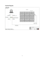
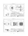
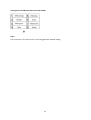
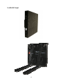
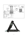
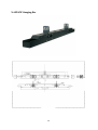
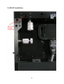
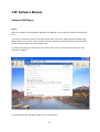
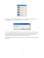
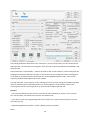
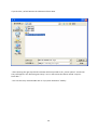
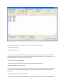
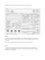
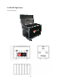
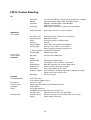
V:LED VSF 10
Manual
Summary
1. Safety Notes S.2
2. Viewing Distance S.3
3. LED Binning S.4
4. Pixel Failure Rate S.4
5. Product Description S.5
6. Specification S.6
7. Aspect Ratio S.8
8. System Diagram S.9
9. Harting PushPull S.10
10. Rental S.13
11. Hanging Bar S.15
12. Installation S.16
13. Software S.17
14. VSC LED Controller S.24
15. Flight Cases S.25
16. Trouble Shooting S.26
1
Thank you for purchasing this V:LED product. For your own safety, please read the
instruction manual carefully before turn on the product for the first time.
SAFETY NOTES
Each person which is responsible for the installation, the use or service of this unit must be:
- qualified
- has to follow the instructions in this manual.
WARNING! Be careful when using the device. You risk an electrical shock from high voltage, if you
touch the wires!
The device has left our company in manufacturer proofed state. To maintain this status and to
ensure a permanent safe operation, it is absolutely necessary to follow the safety instructions and
warnings in this manual.
IMPORTANT: Errors, caused by not following these instructions are not covered by the warranty. The
manufacturer will not accept liability for any resulting defects or problems.
Keep the unit away from radiators or other heat sources!
If the unit has been exposed to tremendous temperature changes (e.g. after transportation), do not
turn it on immediately. The resulting condensation could damage the unit. Don`t switch unit on until
the device reaches room temperature.
This device belongs to protection class I. Therefore, it is imperative that the green/yellow wire is
connected to the earth contact of the plug. The electrical connection must be made by a qualified
person.
Make sure that the cable has never been squeezed or damaged by sharp objects. Check the device
and the cables regularly.
If the cable is damaged, it must be replaced immediately by the manufacturer, its service agent or a
qualified person in order to avoid danger.
Ensure that wires never come in contact with other wires! Handle the power cord and all
connections with caution!
Make sure that the line voltage is not higher than the voltage specified in this manual.
Disconnect the unit from the AC mains when it is not in use or when cleaning it. Disconnect the
connection only by pulling the cable plug.
Defects caused by modifications of the device by unqualified handling or an unqualified person are
not covered by the warranty.
Keep the product away from children and unskilled people.
There are no wear parts in the device. Maintenance and service must be performed only by an
authorized service partner.
Note:
If a earth leakage circuit breaker will be used for a fixed installation, you have to check the leakage
current of the used power supplies. Inside the VSF Panel are AcBel power supplies, whose leakage
current is <3,5mA. The VSF Panel has 2x power supplies and the max. leakage current can be 7mA. If
you use a 30mA earth leakage circuit breaker you can connect 4x VSF Panel with the breaker.
The LED-Panel has an inrush current of 120 Ampere per Panel. A safety fuse must have the
specification „dull“.
Cooling:
If the sun is shinning a LED-Wall of black Panel will be heating-up pretty fast. In the case of sunshine
or high ambient temperature there must be a circulation of air behind the LED Wall. Otherwise the
power supplies shut down automatically at +65°.
LMP advise to use a cooling system for fixed installations of LED Walls.
2
Viewing Distance
Like the min. distance you must have if you are watching TV you must have a min. viewing distance
if you use a VLED LED-Wall, that the viewer will have a good picture.
Minimum Viewing Distance:
The Minimum Viewing Distance (in Meter) of a VLED LED-Wall is the space between the Pixels
measured in mm:
For example: 10mm Pixel Pitch = 10 Meter min. Viewing Distance.
Maximum Viewing Distance:
To calculate the right LED wall size you need the length of the diagonal of the Event hall for
example.
The length of the diagonal will be calculated with the sentence of Phytagora.
Diagonal / 10 = VLED-Wall – min. LED Wall size in sqm
Diagonal / 5 = VLED-Wall – recommended LED Wall size in sqm
Diagonal / 3,5 = VLED-Wall – ideal LED Wall size in sqm
Example for a Screen with an area of 120m x 60m
= 18000sqm => The length of the Diagonal is ca. 135 m.
> The min. VLED Wall size is 13,5qm
> The recommended VLED Wall size is 27 sqm.
> The ideal VLED Wall size is 38 sqm.
3
LED Binning
If the Production of LED’s will be at different points of time the LED’s have tolerances.
For Example:
Rot
Grün
Blau
620 nm +/- 2,5 nm
520 nm +/- 2,5 nm
470 nm +/- 2,5 nm
If a client likes to buy the same LED Panel like he bought before he will see a LED Binning tolerance.
The tolerance can be adjusted manually in the software.
Pixel Failure Rate
The Pixel Failure Rate or Blind Spot Rate is written in the VSF data sheet. The Pixel Failure Rate tells
you how many can be defective until the company LMP will do a warranty repair. If the client wish
the repair of the defective LED’s without the case of warranty he has to pay for these repairs.
4
Product Description
VSF Outdoor LED video walls are mainly intended for external use. The high-quality equipment is
ideally qualified for such applications thanks to its IP 65 (front) and IP 43 (back) implementation and
brightness level, which is sufficient for daylight viewing.
The 'F' in the product designation 'VSF' stands for 'flexibility'. VSF LED video walls commend
themselves not only for installations in the architectural field, such as information boards or outdoor
advertising hoardings in malls and shopping centres, but also for live relays in stadiums (e.g. giant
screen viewing events), and can also be stand-mounted for LED perimeter displays.
VSF LED video walls are available with a pixel pitch of 10mm, making viewing distances of as little as
8 metres possible. Due to the SMD LEDs, wide viewing angles are supported not only in the
horizontal but also the vertical plane. This means that even large numbers of spectators can be plied
with attractive images and information.
To permit rapid assembly and dismantling, a special locking system is used that allows the wall to be
suspended from rigging gear. VSF Outdoor LED video walls come with numerous intelligent solutions
that guarantee simplicity of use. These include waterproof HARTING push/pull connectors.
5
TECHNICAL SPECIFICATIONS - VSF10
OPTICAL SYSTEMS
Optics
Fixed Optics
Beam Angle
120° horizontal/vertical
LED-SOURCE
LEDs
4.608 SMD LEDs
Colours
4.608x red, 4.608x green, 4.608x blue
Diffusor
No
LED-Pixel Pitch
10 mm
Brightness
>5.000 nits
Colour Mixing
RGB
LED-Lifetime
> 50.000 Hours
Blind Spot Rate
3/10.000
LED-Wavelength
red 617,5-622,5 nm,
green 517,5-522,5 nm,
blue 467,5-472,5 nm
TEMPERATURE RANGE
Ambient Temperature
-20°/+50° C
Operating Temperature
Max. 60° C
Cooling
Fan
CONTROL & PROGRAMMING
Protocol
DVI
Control Software
Dbstar LED
Data Cable
Harting PushPull Data RJ45
Data Refresh Rate
800 Hz
6
Grey Lavel
> 12 Bit
TECHNICAL SPECIFICATIONS
Mains Voltage
110-240 V 50-60 Hz
Power Consumption max.
2,6 A at 230 V
Power Consumption avg.
0,87 A at 230 V
HOUSING
Material
Aluminium
Colour
Black
IP Class (Housing)
Front IP65 / Back IP54
MEASUREMENTS/WEIGHT
Measurements (L x W x H)
64 x 72 x 11,7 cm
Weight
19,5 kg
Assembling
Adjustable Hanging Bar
Certificates
CE, EMC class A EN55022, RoHs
SPECIAL FEATURES
Panel Contains All Electronic Parts
No Ethernet-Switch/PSU Necessary
Short-Circuit Protection
Harting PushPull Data- & Power Plugs
Grapical User Interface
Camera Suitable Refresh Rate 800 Hz
DVI Display Grabbing
Compatible To Standard Mediaserver
7
Aspect Ratio VSF10
The VLED VSC Video Scaler can scale the available video signal that the size will fit exactly
to the LED wall. But hasn’t the LED wall an aspect ratio of 4:3 or 16:9 soccer balls will look
like eggs.
Here an example how the aspect ratio will calculated.
Aspect Ratio 4:3
-
The VLED Panel is 640x720mm
The setup is 6x4 Panel
The screen area is 3840 x 2880mm
Calculation: 4/X = 3840mm/2880mm
X = 4 x 2880mm/3840mm
X=3
Aspect Ratio 16:9
-
The VLED Panel is 640x720mm
The setup is 8x4 Panel
The screen area is 5120 x 2880mm
Calculation: 16/X = 5120mm/2880mm
X = 16 x 2880mm/5120mm
X=9
8
System Diagram
9
Harting Push Pull System
10
11
Harting Push Pull RJ45 CAT PIN-Out Standard 568B
Note!
The connectors in the manual can’t be hot plugged under 230VAC voltage.
12
V:LED VSF Panel
13
14
V:LED VSF Hanging Bar
15
V:LED VSF Installation
16
VSF Software Manual
Software XM Player
Step 1:
After the installation of the Software XM Player and WinCap you can start the software with a double
click.
If you start the Software and none message window with „Data send" appears before the Main Page
will be shown, then you don’t have an USB connection between the Software and the VSC Controller.
Please install the USB Driver of the Software CD.
To do the first settings you have to go to the menu point "Control" and choose the sub point "LED
Controller Configure".
The following window will appear. Now click on "Parasetting".
17
The Password you have to type is: dbstarled (It’s the name of the Producer of the Software – the
current XM Player version you can find under: www.dbstarled.com)
Again will be showed the message window "Data send" for a short time. If the window don’t appear
you have none USB connection from the Software to the VSC LED Controller. In this case you have to
check the Hardware-Settings of your PC/Laptop, if the USB / Com-Port is working. Is there an
exclamation mark, you have to install the USB driver from the Software CD.
If everything is working the following window will appear where you can do all important settings for
the LED wall.
18
The setting window has three areas. The "Control list" area at the top shows you the connected VSC
LED Controller. The Controller must be green. Then you have a connection between the Software and
the Controller.
The left side with “screen display”, “position of picture” and “screen rotation” are the settings for the
Sending Card inside the VSC LED Controller. In these areas you can change the colors, the brightness
or the Position of Picture which is the Position for the first grabbed Pixel at X and Y. Also you can
rotate the grabbed Video signal with screen rotation.
The right side with “screen options” and “receiving card array” are the settings for the Receiving Card
which is placed inside the LED Video Panels. The “Screen Options” show the base values of the
receiving card and the “receiving card array” will be used to address the LED wall.
Schritt 2:
- If you use the software for the first time you have to click on the button „import“ in the „control
list“ area and then you choose the rsps-file on the software CD.
- If you want to save your programming you have to click on the „export“ button and you can save
your own rsps-file.
- Programming without Controller: Unclick „display unactive controller”
Note!
19
If you click the „refresh“ Button the software will shut down.
- After choosing the right rsps-file all Parameter will be imported to the „screen options” area and an
entry will appear in the “Receiving Card Array” area. In the Screen Shot above named "output 1:
basic data...".
- You start this entry with a double click or if you press the button "modify".
20
Im Array Options (LED Screen) area you can type in a setup 2x2 LED Panel:
- Receiving Card in line 2
- Receiving Card in row 2
- You have to click on the first Panel which is connected to the data line of the VSC LED Controller
(The 4x Panel have the view from the front side) and then you have to type in the resolution of one
Panel 64x72 Pixel in the Receiving Card Options area.
- Line 64, row 72 for a VSF10 Panel
- If you put in the Pixel values you have to click on the Button „Apply Other”
- Then click „Update all“ and press ok
- To give every single LED Panel an address, you have to click on the LED Panels like they are wired. If
you made an failure with the addressing you can change the address manually if you change the
Index entry.
- Finally you have to press the „OK“ Button
- If you want to use the second output of the VSC LED Controller, you have to do the adressing like
21
above but you have to choose Output 2 in the area “Position of Receiving Card”.
Step 4:
- If you want to change the position where the sending card grabs the Video content you have to
change the X and Y position under „Position of Picture“. In the picture above is the Position X=200
and Y=200.
- In the end you have to press the „Apply“ Button in the area “Position of Picture”.
Step 5:
- You finished the programming fort he VSF LED Panel and the 4x VSF Panel in our example are
grabbing a Picture of 128x144 Pixel at the Position X=200 / Y=200. Now you can leave the Setting
window with the “exit” button.
22
Note!
You can find more special settings for the LED Wall or the Receiving card in the area „screen options“
if you press the Button "other para". But before you change the settings in this area you have to
read the DBstarLED Manual carefully.
23
V:LED VSC LED Controller
The V:LED VSC LED controller offers a wide variety of video inputs to allow the connection of
cameras, media servers, DVD players or other video sources. If you wish to use the LED controller as
more than as a drive unit for a LED wall, it can also serve for the conversion of a video signal, in which
case the maximum latency or processing time is 1 frame.
The output section of the controller offers three video outputs. The VGA output can be used to drive
a preview monitor for the control of the input signal, whilst the DVI output signal is converted into a
digital signal format and routed via a DVI bridge to controller‘s integrated Sending Card. The Sending
Card integrated offers two CAT5 outputs that serve for the connection of the VSO/VSP/VIA LED wall.
The cable run to the first LED wall module in this case can be up to 100 metres in length. If cable runs
in excess of 100 metres are required, a CAT-LWL converter can be used; this is capable of spanning a
distance of 1 km.
The controller can be driven via an RJ11/USB interface or else integrated into an existing network via
its TCP/IP interface and remote-controlled through the network. By this means the controller is able
to scale pixels with precision, so that every input signal can be adjusted to the size of the LED wall
connected. The Sending Card integrated establishes the connection to the VSO/VSP/VIA LED wall by
means of a USB interface and the software LED Studio. This software is in worldwide use and offers
additional functions e.g. time-related brightness control.
If you want to scale an incoming Video signal for the size of the LED wall, you can set the scaling with
the Display Menu of the VSC LED Controller or per software.
For Example: You did the addressing and settings for your LED Wall with the Software LED Studio and
you connect a DVD-Player or a Camera to the VSC LED Controller.
At the front side of the Controller you will find the Button „Scale“. Please push that Button two times
until you see the writing Scale in the Display Menu of the Controller. If push the Buttons „UP“ or
„Down“ the display will show five menu points: „H-Size“, V-Size“, „H-Pos“, „V-Pos“ and „Step“ .
If you have a 10mm VSF Outdoor LED Wall, which has a size of 3,84x2,88m means that you have a
resolution of 384x288 Pixel.
Choose now the Menu point „H-Size“ and confirm the Entry with the „OK“ Button. A little star will
appear next to the Entry „H-Size“. Now you can change the value with the Buttons „UP“ and „Down“,
until you have the value 384. Confirm the Entry with the „OK“ Button. The star will disappear.
That you can change the values faster you can go to the menu point „Step“.
Here you can set the value to 1, 10 or 100. In that effect you can jump in bigger steps with „UP“ or
„Down“.
You have to do the same Steps for the menu point „V-Size“, until you reach the value 288 and
confirm it with the „OK“ Button.
Finally you can change the Offset with „H-Pos“ and „V-Pos“ that the scaled picture starts at another
position.
To save the scaling you have to press the „Save“ Button at the Controller then the „Save 1” or “Save
2” and at last the “OK” Button.
Advice: At the backside of the Controller you will find a VGA and DVI output. If you connect there a
Preview Monitor you can check the scaling.
Further Informations about the VSC LED Controller you will find in the VSP618 Manual.
24
V:LED VSO Flight Cases
For 6x VSF10 Panel
25
VSF10 Trouble Shooting
PC
Not cloned
Adapter
COM Port
Resolution
Use a Preview Monitor, connect to VGA output of the controller
VGA to DVI Adapter didn’t work. Only digital signals
Difficulties with MAC Book, virtual Windows
USB Driver not installed
Wrong VGA resolution, check data sheet of Controller
USB Connection
No Function, Check at "unactive controller"
Schedule Table
Receiving Card
Power
Data Line
LED Controller
Sending Card
Timing Entry which switch the screen to black
Wrong RSPS-Datei
Timing Entry which shut down Power
defective
Check Video signal with Preview Monitor
Hang up, Check LED’s at CAT outputs
Power Supply for Sending Card defective
Internal CAT cable loose
USB Input defective
DBstarLED
Screen black
1. Receiving Card
Sending Card
Screen Pixel
Failure/Stripes
Controller
DVI cable
Output
Sending Card
Save
Didn’t Boot up
Display dead
Old Scaling
Analog vs. Digital
DVI Bridge
LED Wall
LED module black
Panel black
2 LED's vertical
Red Stripe
Stripes
Circuit Breaker
Change DVI or HDMI cable
Wrong output programmed
Save Button -> Save 1 Button -> OK Button
Backside Controller: DIP switches down not up
Check of internal data cable to display
Press Output Button to take it out
If you change the incoming signal from a digital to an analog
Signal you will have a black frame
Check connection
Loose data cable
In or Output of module defect
Loose CAT cable
Soldering between Driver and LED Board defective
Heat Problem
Send again RSPS file
Hub Board of Receiving Card hasn’t the right seat
Flat data cable
Connector turned 180° at the Hub Board
Defective Power
Disconnect one by one Panel from Power to see which
Supply
Power Supply is defective
26


![English-T series-NOVA-User manual-F [兼容模式]](http://vs1.manualzilla.com/store/data/005791006_1-acba31ea472695c25db426bea2198a0f-150x150.png)