1
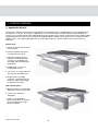
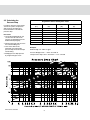
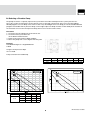
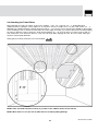
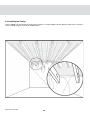
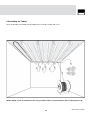
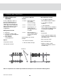
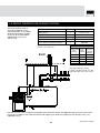
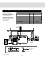
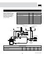
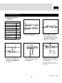
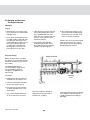
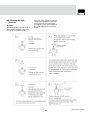
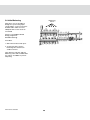
®
Climate Trak
Heating System
Installation Manual
February 2009
Working with
Viega is the perfect
solution.
Viega researches, develops,
and produces complete system
solutions for contractors in the
technical building installation
business. The components
are produced at our plants or
are supplied exclusively by the
finest quality manufacturers.
Each of our systems is
developed in-house and tested
under stringent quality control
conditions to guarantee safety
and efficient operation.
An international
company with
a national
commitment.
Viega recognizes that many of
the advances in our industry
have their beginnings in
Europe. However, that does
not mean North America
deserves anything less.
Therefore, we have been
the pioneer in combining
technology from both sides of
the Atlantic into the very best
plumbing and heating systems
for our customers.
Our goal is to remain in the
forefront of the plumbing and
heating industry well into
the new century, and with
our advanced products and
a determination to remain
the quality leader, we are
convinced this accomplishment
is well within our reach.
Disclaimer: Systems should be
protected from freezing at all
times. Proper insulation or glycol
mixture may be needed in system
if not used for an extended period
of the heating season.
IM-PR-Climate Trak 0209
2
Welcome
By choosing to install a Climate Trak
System, you have joined the ranks
of heating system installers across
the country who believe there is no
substitute for quality.
Viega has a history of bringing high
quality and innovative technology to
the hydronic marketplace in
North America.
It is the business of our engineers
to research and develop complete
systems that provide you the
most effective and easy-to-use
products available.
In the following pages, you will be
guided through the system design,
layout, installation and start-up of
our Climate Trak System.
We look forward to sharing our
history in the making with you.
Call 800-976-9819 for your
local representative and
wholesale location.
CONTENTS
APPENDIX A
1 System Overview
1.1
Making a Press Connection. . . . . . . . . . . . . . . . . . . . . . . . 30
Application Benefits . . . . . . . . . . . . . . . . . . . . . . . . . . 4
APPENDIX B
2 System Design
2.1
2.2
2.3
2.4
2.5
2.6
SVC Compression Coupling 3/8"- 5/8" . . . . . . . . . . . . . . 31
Calculating a Materials List. . . . . . . . . . . . . . . . . . . . . 5
Heat Loss Calculations for Floor Heating Systems
Using Radiant Wizard . . . . . . . . . . . . . . . . . . . . . . . . . .6
Calculating the Supply Water Temperature . . . . . . . .6
Calculating the Floor Surface Temperature . . . . . . . .7
Calculating the Pressure Drop . . . . . . . . . . . . . . . . . . 8
Selecting a Circulator Pump. . . . . . . . . . . . . . . . . . . . 9
APPENDIX C
Recommended Tools for Installation . . . . . . . . . . . . . . . . 32
APPENDIX D
R-Value Table Floor Coverings . . . . . . . . . . . . . . . . . . . . . 33
APPENDIX E
3 Climate Trak/Heat Transfer Plate
System Installation
3.1
3.2
3.3
3.4
3.5
3.6
Pre-installation Tip Page . . . . . . . . . . . . . . . . . . . . . .
Clearing the Bays . . . . . . . . . . . . . . . . . . . . . . . . . . .
Drilling Tubing Holes . . . . . . . . . . . . . . . . . . . . . . . . .
Attaching the Traks/Plates . . . . . . . . . . . . . . . . . . . .
Installing the Tubing . . . . . . . . . . . . . . . . . . . . . . . . .
Post-installation Tip Page . . . . . . . . . . . . . . . . . . . . .
Supply Water Temperature/BTU Output Charts . . . . . . . 34
APPENDIX F
10
11
12
13
14
19
Making a Materials List . . . . . . . . . . . . . . . . . . . . . . . . . . . 37
4 Piping and Controls
4.1
4.2
4.3
Mixing Station and Manifolds. . . . . . . . . . . . . . . . . . 20
Single and Multiple Temperature Schematics . . . . 21
Zone Wiring . . . . . . . . . . . . . . . . . . . . . . . . . . . . . . . . 24
5 System Start-up
5.1
5.2
5.3
5.4
Station and Actuator Installation . . . . . . . . . . . . . . .
Purging and Pressure Testing the System . . . . . . .
Adjusting the High Limit Kit . . . . . . . . . . . . . . . . . . .
Initial Balancing . . . . . . . . . . . . . . . . . . . . . . . . . . . . .
25
26
27
28
6 Finish Flooring
6.1
Choosing a Finished Floor . . . . . . . . . . . . . . . . . . . . 29
3
IM-PR-Climate Trak 0209
1.
SYSTEM OVERVIEW
CONTENTS
1.1 Application Benefits
Climate Traks and Heat Transfer Plates are designed for retrofit applications or in applications where the buildup above
the subfloor is a concern. These types of applications are not the most efficient kind of radiant heating compared to
systems such as Viega Climate Panel and Viega Snap Panel, but deliver the comfort of having warm floors and full radiant
heating throughout the house. Both methods utilize ViegaPEX Barrier Tubing and attach directly to the underside of the
subfloor. This is a fast, lightweight application to install and provides the comfort of radiant heat the homeowner is
looking for.
Climate Trak:
1. Heavier aluminum than the Heat
Transfer Plates
2. Fastest installation time (does
not require Groove Tube)
3. Easiest to install (Traks and
tubing are installed separately,
so there is no struggling with
the tubing while the fastening is
being done)
4. Predrilled holes for ease of
fastening with screws
5. Comes in 4' or 8' long Traks that
also help with installation time
6. Snap-in groove for tubing
maximizes contact between the
aluminum and the PEX Tubing
for efficient heat transfer
Heat Transfer Plates:
1. Made from thinner, more flexible
aluminum than the Climate Traks
2. Comes in 20" long by 5"
wide plates
3. Requires a small bead of
Groove Tube down the channel
where the tubing is run right
before installation
IM-PR-Climate Trak 0209
4
2.
SYSTEM DESIGN
CONTENTS
2.1 Calculating a Materials List
Multipliers For Climate Traks
Tubing
OC
6"
8"
9"
12"
16"
18"
Plate
Size
4'
8'
4'
8'
4'
8'
4'
8'
4'
8'
4'
8'
Tubing
Multiplier
Multipliers For Heat Transfer Plates
Trak
Multiplier
.47
.23
.35
.18
.31
.16
.23
.12
.18
.09
.16
.08
2.2
1.7
1.5
1.1
.85
.75
Tubing
OC
Tubing
Multiplier
Plate
Multiplier
6"
2.2
.93
8"
1.7
.70
9"
1.5
.62
12"
1.1
.47
16"
.85
.35
18"
.75
.31
Maximum Circuit Length
≤25 BTU/ft2
26-35 BTU/ft2
3/8"
300 ft.
250 ft.
1/2"
400 ft.
350 ft.
Example: Heated Area - 1,500 sq. ft.
Calculating Number of Traks
8' Climate Traks 8" O.C.
# of Traks = 1,500 sq. ft. x .18
# of Traks = 270
- Sold in packages of 20:
(round up to order 14 boxes)
Calculating Amount of Tubing
Amount of Tubing = 1,500 sq. ft. x 1.7
Amount of Tubing = 2,550 ft.
Calculating Number of Circuits (≤25 BTU/ft2)
Amount of Tubing = 2,550 ft.
2550 ft./400 ft. = 6.375
# of 1/2" circuits = 7
1. Calculate the total heated area.
2. Using the charts above and the total area, calculate
the total number of Traks/Plates and amount of tubing
needed for the job.
3. Using the circuit length chart, calculate the total
number of circuits needed.
5
IM-PR-Climate Trak 0209
The easy-to-use Radiant Wizard
program will help calculate the heat
loss of any residential building.
Based on ASHRAE formulas, the
Radiant Wizard will also perform
a full, multi-temperature, room
by room, detailed design while
calculating a materials list and price
for your system. A step-by-step
user manual is provided with the
program to help you with
the process. Available in
the program is a full list of
all Viega ProRadiant and
PureFlow products, product
instructions, specification
sheets, manuals and
catalogs. Once Radiant
Wizard is installed on your
computer, updating to the
latest version is quick and
easily accomplished online.
Contact your local Viega
District Manager to receive
a copy of the Radiant
Wizard program.
0.25
0.5
1.0
2.0
3.0
Total R-Value of Finished Floor Above Subfloor
2.2 Heat Loss Calculations
for Floor Heating
Systems Using Radiant
Wizard®
Supply Water Temperature (°F)
Based on 68°F room temperature with R19 insulation between joists
2.3 Calculating the Supply
Water Temperature
Procedure:
2. Follow to the right until you reach
the selected total R-value curve.
1. Locate desired BTU output (from
Radiant Wizard) on left
vertical axis.
3. Then move down to the
horizontal axis and read the
supply water temperature.
IM-PR-Climate Trak 0209
6
(For additional Climate Trak/Heat
Transfer Plate BTU output charts,
refer to Appendix E).
2.4 Calculating the Floor
Surface Temperature
This chart shows the relation
between room temperature and
floor surface temperature for floor
heating systems.
Procedure:
Example:
1. Locate desired output (from
Radiant Wizard or other source)
on left vertical axis.
Output needed: 25 BTU/h/ft2
Room temperature: 68°F
2. Follow to the right until you reach
the curve.
Temperature ΔT
(from chart): ~ 12°F
3. Then move down to the horizontal
axis and read the ΔT between the
room temperature and the floor
surface temperature.
Floor surface temperature:
68°F + 12°F = 80°F
4. Add the room temperature and
the ΔT to get the floor surface
temperature.
The floor surface temperature will
be 80°F with 25 BTU/h/ft2 output
and 68°F room temperature.
Floor Surface Temperature Chart
7
IM-PR-Climate Trak 0209
2.5 Calculating the
Pressure Drop
ViegaPEX™ Barrier Tubing Data Table
In order to select the correct pump
size for the system, the pressure
drop must be calculated. Use
the chart below to calculate the
pressure drop.
Water Content
(in.)
Nominal Size
(in.)
Outside Diameter
(in.)
*5/16
0.430
0.292
0.004
3/8
0.500
0.350
0.005
Inside Diameter
(in.)
1/2
0.625
0.475
0.009
Procedure:
5/8
0.750
0.574
0.014
1. Locate desired flowrate for one
circuit on the left vertical axis
(receive circuit flowrate from the
Radiant Wizard program).
3/4
0.875
0.671
0.018
2. Follow to the right until you reach
the selected tubing size.
1
1.125
0.862
0.030
1-1/4
1.375
1.053
0.045
1-1/2
1.625
1.243
0.063
*5/16" used in Climate Panel installation.
3. Then move down to the
horizontal axis and read the
pressure drop in feet of head per
foot of tubing.
Example:
GPM through 1/2" PEX: 0.7 gpm
Pressure drop per foot: ~ .022 ft. of head / ft.
4. Multiply pressure drop per foot
by length of longest circuit.
Total pressure drop: .022 x 350 total ft. = 7.7 ft. of head
/2”
/4”
1-1
1-1
50
1”
30
3/4”
”
20
5/8
”
10
1/2
7
”
3/8
6
”
4
5/16
3
2
1
/S
FT
IM-PR-Climate Trak 0209
8
2.6 Selecting a Circulator Pump
The pump must have a capacity equal to the system flow rate and a head equal to the system pressure loss.
These two system characteristics are the primary ones in selecting a pump. Flow rates come from the Radiant
Wizard program. Pressure drop comes from section 2.5 (Calculating the Pressure Drop) or from the Radiant Wizard
program. Remember that for pressure drop, use the highest pressure drop of all the circuits fed by their circulator. If
the circulator can overcome that pressure drop, then it can overcome all the others.
Procedure
1. Locate the pressure drop on the left vertical axis.
2. Locate the total system flow rate
on the bottom horizontal axis.
3. Follow to the intersection of both variables.
4. Select the pump with a curve higher than this point.
Example
Total GPM through 1/2" ViegaPEX Barrier:
5 GPM
Longest circuit pressure drop:
10 ft. of head
Pump selected: Low Head Pump
Stock Code
Stock Code
12126
Speed
Amps
Watts
HP
HI
0.75
87
1/25
MED
0.66
80
1/25
LOW
0.55
60
1/25
A
B
12126
6-1/2"
12127
6-1/2"
9
C
D
E
F
5-1/4"
4"
4-3/16"
3"
3-5/32"
6"
4-7/8"
3-1/2"
3-7/16"
3-5/32"
IM-PR-Climate Trak 0209
3. CLIMATE TRAK / HEAT TRANSFER PLATE SYSTEM INSTALLATION
3.1 Pre-Installation
Tip Page
Place the Traks for the most even
heat distribution.
Dimensions in drawing are based
on standard 2" by 8", 2" by 10" or
2" by 12" floor joists on 16"
centers. Adjust spacing as needed
when using engineered joists or
different spacing.
Avoiding Obstructions
It is important not to install the Traks around objects that will restrict the tubing from being installed into the Traks. In
the example below, if the Traks were run on the inside of the dropping pipe, you would find that the tubing would be
unable to be snapped in. This is why the Traks are shown going to the outside of the dropping pipe.
IM-PR-Climate Trak 0209
10
3.2 Clearing the Bays
If support crosses can be easily removed, take them out to clear bays for easier installation of the plates and Traks. If
crosses are unable to be removed, DO NOT drop tubing below them and resume on the other side; install both plates
and tubing above crosses so that no area is lost. Nails must also be removed from bays. Whether you cut them, grind
them or carefully bend them over, be careful not to damage the finished floor above. (When cutting nails, be sure to
wear safety glasses.
)
11
IM-PR-Climate Trak 0209
3.3 Drilling Tubing Holes
Determine where the manifold will be located, then from there, decide which end of the bays the tubing will be
returning down. Use a right angle drill with a 1-1/4" bit to drill a series of holes through each floor joist. Be sure to
keep holes at least 3" from the subfloor to avoid floor nails, although having the holes centered would be the best
for structural strength.
Map out the circuits and determine which bays go to which circuits. Be careful not to exceed maximum circuit length
for the size of tubing you are using (3/8" - 300 ft., 1/2" - 400 ft.).
NOTE: Be sure to check with local building codes to ensure no structural damage will occur with
drilling the joists.
IM-PR-Climate Trak 0209
12
3.4 Attaching the Traks/Plates
Start attaching the Traks via staples or zip screws (staples - 7/16"- 1/2" crown by 3/4" - 1", depending upon
subfloor thickness; putting in 18-20 staples for an 8 ft. piece and 10-12 staples for a 4 ft. piece; zip screws 3/4" - 1",
depending on subfloor thickness). Begin attaching Traks 8" - 10" from the closest hole that was drilled to allow ample
room for tubing to turn. Continue to install Traks the entire length of the bay (or to where desired circuit ends) keeping
the space in between Traks to around 1". Stop Trak installation 12" - 16" short of where you want circuit to end (i.e.,
wall, main beam, room above) to allow for a non-stressful loop. When stapling up Traks, be sure to keep staple gun
square to avoid staple deflection.
Safety glasses and ear protection are recommended.
NOTE: Traks should be attached as flush as possible to the subfloor for best heat transfer.
NOTE: When Traks are cut, be sure to debur them to avoid any tubing damage.
13
IM-PR-Climate Trak 0209
3.5 Installing the Tubing
Begin to make non-stressful (teardrop) type loops for each of the bays, keeping loops small and manageable.
IM-PR-Climate Trak 0209
14
3.5 Installing the Tubing
Continue making the “teardrop” loops, being sure not to install any of the tubing into the Traks yet. Keep loops fairly
small and manageable to prevent twisting while keeping the loops easy to transfer tubing through.
15
IM-PR-Climate Trak 0209
3.5 Installing the Tubing
Transfer tubing from the decoiler through loops until there is enough tubing to fill the final bay and make the run back
to the manifold using the second set of drilled holes.
IM-PR-Climate Trak 0209
16
3.5 Installing the Tubing
Once the final bay is installed, transfer tubing from coil to fill next bay and so on.
NOTE: Tubing can be installed into Traks using a rubber mallet or a palm hammer with a medium plastic tip.
17
IM-PR-Climate Trak 0209
3.5 Installing the Tubing
Continue transferring the tubing through the loops, finishing one bay at a time.
IM-PR-Climate Trak 0209
18
3.6 Post-installation Tip Page
Foil Face or Radiant Barrier
Insulation
Insulation should always be used
in a staple-up radiant installation.
Ideally there should a 1" - 2"
air gap in between the insulation
and the Traks/Plates.
However, the air gap should only
be left if that space is considered
a dead air space (absolutely no air
current through it, whether it be
from an outside wall, from below,
or through holes in the subfloor).
Any air current through this space
will decrease the performance of
the system and the insulation. By
insulating outside walls, sealing
any large gaps in the subfloor and
ensuring that the insulation is tight
against the joist, this will create
a situation where the air gap is
beneficial to the performance of
the system.
If a dead air space is unable
to be achieved, then the insulation
should be pushed up lightly
against the Traks/Plates.
Insulation Blocking
Inside Wall
Outside Wall
To create a dead air space, begin
by insulating the outside ends
of the joist bays with a separate
piece of insulation (insulation
blocking) between the top of
the foundation and the bottom
of the subfloor to keep cold air
from entering through sills and
outside walls.
R19 Insulation
From Decoiler
To Manifold
Note: When using expanding foam insulation on and around the PEX
tubing, please contact the manufacturer of the foam or Viega for
PEX compatability issues. Some foams my cause excessive heat if
installed improperly. This excessive heat may cause damage to
the PEX.
19
IM-PR-Climate Trak 0209
4.
PIPING AND CONTROLS
CONTENTS
4.1 Mixing Station and
Manifolds
1-1/4" Stainless Manifold
Includes
In many applications either an
Injection or Mixing Station can
be used; however, because a
staple-up system generally uses
10-20° higher water temperature,
Viega recommends only using a
Mixing Station with this type
of application.
2 - 6-5/8" - Spacing brackets
(for compact
remote mounting)
2 to 12 -
Outlets per header
2 to 12 -
Balancing valves on
supply header for
flow adjustment from
0-2 GPM
2 to 12 -
Shut-off valves on
return header designed
to receive powerheads
(15061)
Mixing Station Includes
2 - Ball valves
1 - Pump (low, medium, high)
1 - Diverting valve with integrated
high temp. limit
2 - 6-5/8" Spacing
mounting brackets
Options
Two position actuator
Other Manifolds Available
r1-1/4" Stainless Manifold
Shut-Off/Balancing/Flow Meters
r1-1/4" Stainless Manifold
Valveless
r1" Brass Manifold
(when using the brass manifold, an
accessory kit is needed for proper
air elimination and purging)
Options
Built-in purge valves and air
bleeders
r1PXFSIFBET
r$JSDVJUUFNQFSBUVSFHBVHFTVTFE
with Stainless Shut-Off/Balancing/
Flow Meters only)
r47$DJSDVJUáPXNFUFST
1-1/4" Union Connections
r47$DJSDVJUCBMMWBMWFT
1" NPT removable end caps
r3FEVDFSTGPSEJSFDUTUBUJPO
attachment (needed for stainless
manifolds only)
Three position actuator
Reducers
Note: It is important to use Teflon tape and thread sealant paste on all connections without gaskets.
IM-PR-Climate Trak 0209
20
4.2
SINGLE TEMPERATURE RADIANT SYSTEM
CONTENTS
The Basic Heating Control is
selected to modulate system
water temperature as the outdoor
temperature fluctuates. Multiple
zones may be incorporated by
adding Thermostats and a
Zone Control.
Material
Quantity
Stock Code
Mixing Station
1
12120 - 12125
Basic Heating Control
1
16015
Indoor Sensor
1
16016
Three Position Actuator for Station
1
18003
1-1/4" Stainless Manifold, # Outlets*
1
15900-910
*Based on job requirements
Primary Loop Sizing*
3/4
4
Heat
Carrying
Capacity
(BTU/hr)
40,000
1
8
80,000
1-1/4
14
140,000
1-1/2
22
220,000
2
45
450,000
Copper Pipe
Size
(inches)
B.H.C.
B.H.C
Flow
Rate
(GPM)
*Flow Rate and Heat Carrying
Capacity calculation based on a 20°F
temperature drop across the system.
Note: All schematics are conceptual. The designer must determine whether this application will work in the system and
must ensure compliance with national and local code requirements. Boiler trim (expansion tank, fill valve, relays, etc.)
supplied by others.
21
IM-PR-Climate Trak 0209
4.2
SINGLE TEMPERATURE RADIANT SYSTEM WITH BOILER MODULATION AND OPTIONAL DHW CONTROL
CONTENTS
The Advanced Heating Control
incorporates low temperature
mixing, provides boiler modulation,
and the option of domestic hot
water control with priority.
Optional DHW sensor may be in
tank or on outlet piping. If boiler
and DHW control are not needed,
refer to Basic Heating
Control diagrams.
Material
Quantity
Stock Code
Mixing Station
1
12120 - 12125
Advanced Heating Control
1
16014
Indoor Sensor
1
16016
Three Position Actuator for Station
1
18003
1-1/4" Stainless Manifold, # Outlets*
1
15700 - 15710
Thermostats
*
18002
Powerheads
3
15061
Optional DHW Sensor
1
16018
Transformer 24V
1
18008, 18020
*Based on job requirements
A.H.C.
A.H.C.
Primary Pump
Supply Sensor
S1
P2
System Pump
3 Position
Actuator
Return Manifold
3 Position Actuator
Air Eliminator
Back Flow Preventor
Cold Water Supply
Pressure Reducing Valve
Expansion Tank
Supply Manifold
IM-PR-Climate Trak 0209
22
4.2
MULTIPLE TEMPERATURE RADIANT SYSTEM WITH BOILER MODULATION AND OPTIONAL DHW CONTROL
CONTENTS
Note: If the heat loss and
required water temperature varies
throughout a building, a multiple
water temperature system may
be required. To add an additional
temperature system, pipe in
another Mixing Station with the
necessary controls.
Material
Quantity
Stock Code
Mixing Station
2
12120 - 12125
Basic Heating Control
2
16015
Indoor Sensor
2
16016
Three Position Actuator for Station
2
18003
1-1/4" Stainless Manifold, # Outlets*
2
15012-022
Zone Control
2
18032
Thermostats
*
18029-031
Powerheads
*
15061
Optional DHW Sensor
1
16018
Transformer 24V
1
18008, 020
*Based on job requirements
Outdoor Sensor
Indoor Sensor
B.H.C.
B.H.C
B.H.C.
B.H.C
Supply Sensor
System Pump
3 Position
actuator
Primary Loop Sizing
Copper Pipe Size [inch]
Flow Rate* [GPM]
Heat Carrying Capacity [BTU/h]
3/4
1
1-1/4
1-1/2
2
4
8
14
22
45
40,000
80,000
140,000
220,000
450,000
*Based on 6 FPS
23
IM-PR-Climate Trak 0209
4.3 Zone Wiring
A manifold system allows any
one or more of the circuits to
be adapted for control by a
thermostat. The following are
typical zone wiring schematics.
Detailed wiring diagrams are
provided with products.
Important Note:
Installation by a licensed electrician
is recommended. Installation and
use of this equipment should be
in accordance with provisions of
the U.S. National Electric Code,
applicable local code and pertinent
industry standards.
Wiring Schematic: One Zone Application
Digital Thermostat
C C R W NTC A/B
24 VAC
TRANSFORMER
Floor sensor
WHITE
BLACK
120 VAC
INPUT
Note: Digital Thermostats can
control up to 4 powerheads.
Wiring Schematic: Multi-Zone Application
Digital Thermostat
CCRW
RWC
Note: 4 Zone Control (18060)
can operate 8 powerheads.
6 Zone Control (18062) can
operate 16 powerheads.
MAIN
END
SWITCH
T
T
4 & 6 Zone Control
BOILER
EXTRA
END
SWITCH
N/O COM N/C
SYSTEM CIRCULATOR
DHW CIRCULATOR
120 VAC
Y1 Y2 R1 R2
IM-PR-Climate Trak 0209
NEUTRAL
HOT
5. SYSTEM START-UP
5.1 Station and Actuator
Installation
Material
Product
Quantity
Mixing Station
1
Three Position Actuator
1
Manifold, # outlets*
1
Basic Heating Control
1
Indoor Sensor
1
FostaPEX
*
Press Adapters
4
Compression PEX Adapters
*
1. Mount the Mixing Station using
the mounting brackets.
2. Make the press connection
for the supply and return lines
to the Mixing Station on the
copper tee. Install tees as close
as possible to keep pressure
difference at a minimum.
4. Use the SVC Compression or
PEX Press Adapters to connect
the ViegaPEX Barrier lines to
the manifold.
5. Remove the grey cap from the
diverting valve on the Mixing
Station and screw the actuator
on hand tight.†
*Based on job requirements
3. Connect the supply and
return lines by soldering on a
ViegaPEX Press adapter, then
pressing on ViegaPEX Barrier
or FostaPEX.
† Perform step 5 after the system has
been filled and purged; refer to section 5.2
for procedure.
25
IM-PR-Climate Trak 0209
5.2 Purging and Pressure
Testing the System
Operation
Purging
1. Attach drain hose to purge valve
hose connection on return header
and open valve.
2. Close all but one balancing valve
on supply header (under red caps,
turn with 5mm allen key). Close
isolation ball valve on boiler return
line. Remove plastic dust cap
or temperature controller from
diverting valve, and make sure
that high limit kit is fully open.
3. Open boiler fast fill valve to purge
circuit. After purging first circuit,
close red balancing valve and
open next one. Continue with one
circuit at a time until all circuits
have been purged.
4. Close purge valve and open
all balancing and boiler valves.
Reset high-limit kit, and reinstall
actuator onto diverting valve.
5. Any remaining air pockets in the
system will be eliminated through
the automatic air vent after a few
hours of constant circulation.
NOTE: If the system must be purged
again in the future for any reason,
the high-limit kit must be reopened
during purging for full flow.
Pressure Testing
Supply Manifold
Before the finish floor is installed,
the radiant system must be pressure
tested. Air or water may be used as
the medium.
The following procedure is
recommended by Viega. Check
the local building codes for
compliance or additional test
requirements.
Procedure:
Diverting
Valve
1. Double-check all connections to
manifold to ensure proper seal.
2. Connect manifold pressurization
kit (1) to any purge valve (2).
3. Pressurize the system to 80 psi
to detect potential nail or screw
penetrations.
4. The system should hold the 80
psi for a minimum of 24 hours.
IM-PR-Climate Trak 0209
Note: If the tubing is damaged,
repair punctured section with a
compression coupling.
26
Contractor: Maintain pressure during
the installation of the finish floor to
simplify leak detection if tubing is
damaged.
5.3 Adjusting the High
Limit Kit
Operation
The Mixing Station is provided with a
preinstalled temperature High Limit
Kit. This kit is installed into the
three-way valve to allow a maximum
supply water temperature to be set.
This kit must be unscrewed when
purging the system, and should then
be set according to the instructions
below.
27
IM-PR-Climate Trak 0209
5.4 Initial Balancing
Balancing
Valves
Many times it is not possible to
design the system using equal
circuit lengths, so the system must
be balanced in order to ensure
adequate flow to each circuit on
a manifold.
(Refer to your Radiant Wizard
design program for
detailed balancing).
Procedure:
1. Start with all valves wide open.
2. To decrease flow, turn the
balancing valve clockwise in
small increments.
Note: Remove red caps and turn
balancing valves with included allen
key. Valves are hidden to prevent
tampering.
IM-PR-Climate Trak 0209
28
6. FINISH FLOORING
6.1 Choosing a Finished
Floor
There are three common types of
finished floors used in residential
construction: wood floors, tile/vinyl,
and carpet.
When picking a finished floor, the
lower the R-value, the better radiant
heat will work. When using tile, the
R-value will be low and therefore
will work very well with your radiant
system (Appendix D on page 33
lists some common tiles and their
R-values).
Vinyl flooring is another common
choice for kitchens and baths and
has a low R-value.
Using carpet over radiant heating
requires careful planning. Viega’s
recommendation for a covering
over a radiant system is to not
exceed a total of a 2.5 R-value (the
carpet pad plus the carpet itself).
Remember that the pad and the
carpet are insulators and will
restrict the heat from getting into
the room, so keeping the R-value
of the pad and the carpet low is a
must in below subfloor application
(Appendix D on page 33 lists some
carpet and pad R-values). It may
be necessary to add supplemental
heat or install hydronic baseboards
in rooms with heavy carpeting (see
Viega’s Combiflex system).
There are many questions regarding
hardwood flooring over radiant
heating. Armed with knowledge
and a few precautions, hardwood
floors and radiant heat will work
well together. There are two
important issues:
Floor Surface Temperatures
For many builders, a reluctance
to install hardwood floors over
radiant heat stems from problems
associated with incorrect control of
the floor surface temperatures.
r5PEBZNPEFSOJOTVMBUJPOBOE
building techniques allow a
radiant floor to stay cooler than
the floor of the average sunroom.
r5IFáPPSTVSGBDFUFNQFSBUVSF
should not exceed 85°F (refer to
section 2.4 to calculate the floor
surface temperature).
Also be careful when using multiple
or high R-value area rugs over
hardwood flooring. Your radiant
heating system must be designed
with this additional R-value taken
into account in order to perform
properly. If the system was
designed for bare wood flooring,
adding area rugs may lead to a
situation where heat output
is diminished.
Moisture
Dry Shrinkage
If the moisture content is relatively
high near the top surface of the
plank, it will crown downward on
the edges.
Wet Expansion
Sources from below:
r*OBEFRVBUFNPJTUVSFCBSSJFS
r(SPVOEXBUFSXJDLJOHUISPVHI
the slab
r6OTFBMFETVCáPPS
Allow the radiant system to run for
at least a week before installing
the hardwood. This will ensure that
the subfloor is dry. Wood flooring
should be acclimated to the job site
before installation. When checking
the moisture content of the subfloor
and wood flooring with a moisture
meter, aim for a reading of 6%
to 8%. Moisture will affect the
hardwood floor with or without a
radiant system.
r.PJTUVSFBCTPSQUJPODBVTFTXPPE
to swell.
r.PJTUVSFMPTTDBVTFTXPPE
to shrink.
1. Floor surface temperatures
2. Moisture
of the plank, cupping upward will
occur exaggerating cracks.
If the moisture content of the wood
is relatively high near the bottom
29
Sources from above:
r)JHISFMBUJWFIVNJEJUZ
Both solid plank flooring and
engineered wood floors are
acceptable choices over
radiant heating.
Choosing narrower planks
and harder woods minimizes
dimensional change in the wood.
Engineered wood flooring usually
has less expansion and contraction
and can be a good choice to
minimize gaps between planks.
Note: Follow the flooring
manufacturer’s installation manual
or NOFMA’s (National Oak Flooring
Manufacturers Association) manual.
IM-PR-Climate Trak 0209
MAKING
A PRESS CONNECTION - APPENDIX A
CONTENTS
When piping a Mixing Station
to a primary loop, FostaPEX
is suggested. This method will
produce a higher quality outcome,
while reducing installation time.
Follow these steps each time you
make a FostaPEX connection.
1. Square off tubing to
proper length.
2. Insert FostaPEX tubing into prep
tool. Push and turn tool until no
more resistance is felt and tool
spins freely. (This step applies to
FostaPEX only)
3. Slide press sleeve fully over end
of tubing.
4. Insert compression fitting into
tubing and engage fully.
5. Check full tubing insertion at view
hole of sleeve.
6. Engage press tool perpendicular
over press sleeve and close
tool jaws.
7. Start tool ratchet until automatic
tool release occurs at proper
compression force.
8. Warning: The connection is not
leakproof when the tool has been
opened by emergency release.
IM-PR-Climate Trak 0209
30
Viega IM-PRCT 0209
CONTENTS
SVC
COMPRESSION COUPLING 3/8"- 5/8" - APPENDIX B
1. Square off tubing to proper length. Slide
compression nut up tubing and slip brass ferrule
over tubing.
2. Slide tubing over end of SVC adapter, pushing it on
fully until tubing is flush with shoulder of fitting.
3. Insert adapter into SVC coupling and tighten
compression nut to SVC coupling to secure
adapter. Re-tighten compression nut slightly after
30 mins.
4. Repeat the same procedure for the other side of the
SVC compression coupling.
31
IM-PR-Climate Trak 0209
CONTENTS
RECOMMENDED
TOOLS FOR INSTALLATION - APPENDIX C
t*OTUBMMBUJPO1PXFS5PPMT
t
1. Staple Gun with swivel connected hose (staples - 7/16" - 1/2" crown by 3/4" - 1")
2. Compressor (1.5-2 hp)
3. Radial Arm Chop Saw - for cutting Traks
4. Right Angle Drill with bit kit (1-1/4") - for drilling joists
5. Palm Hammer (medium plastic hammer tip)
6. Screw Gun (3/4" - 1" tech screws)
7. Nail Grinder (4-1/2")
t*OTUBMMBUJPO)BOE5PPMT
t
1. Tape Measure (recommended 1 per person)
2. Heavy-Duty Nail Cutter - cleaning joists
3. Rubber Mallet - snapping tubing into Climate Traks
4. Decoiler
5. Hammer - bending nails, miscellaneous
6. Chalk Line - chalking joists for hole or plate placement
7. Wrench - manifold connections
8. Tubing Cutter
9. Utility Knives (deburring and opening boxes)
10. Caulking Gun (only with heat transfer plates)
t.JTDFMMBOFPVTt
1. Safety Glasses (highly recommended!)
2. Earplugs
3. Rolling Scaffolding or Sheet-rocker Stilts or Ladders
4. Lights (especially in basement applications)
5. Broom
IM-PR-Climate Trak 0209
32
R-VALUE
TABLE FLOOR COVERINGS - APPENDIX D
CONTENTS
Building Board
Gypsum or Plaster Board
Plywood
Particleboard, low density
Particleboard, medium density
Particleboard, high density
Waferboard
Wood Subfloor
Cement board
Tile
Ceramic Tile
Marble
Granite
Slate
Linoleum or Vinyl
Rubber, hard
Cork Tile
Carpet Pad
Waffled Sponge Rubber
Synthetic Jute
Bonded Urethane, 4 lb Density
Bonded Urethane, 8 lb Density
Prime Urethane, 2.2 lb Density
Carpet
Acrylic Level Loop
Acrylic Level Loop w/ Foam Back
Acrylic Plush
Polyester Plush
Nylon Level Loop
Nylon Plush
Nylon Shag
Nylon Saxony
Wool Plush
Hardwood
Ash
Beech
Cherry
Elm
Maple
Oak
Cedar
Fir
Hemlock
Pine
Redwood
Spruce
Engineered Flooring
Laminated Parquet Flooring
1/8"
1/4"
3/8"
1/2"
5/8"
3/4"
7/8"
1"
0.11
0.16
0.18
0.13
0.11
0.20
0.16
0.03
0.23
0.31
0.35
0.27
0.21
0.40
0.31
0.06
0.32
0.47
0.53
0.40
0.32
0.60
0.47
0.09
0.45
0.62
0.71
0.53
0.43
0.80
0.62
0.12
0.56
0.77
0.88
0.66
0.53
0.99
0.78
0.15
0.68
0.93
1.06
0.80
0.64
1.19
0.93
0.18
0.79
1.09
1.23
0.93
0.74
1.39
1.09
0.21
0.90
1.24
1.41
1.06
0.85
1.59
1.24
0.24
0.02
0.01
0.01
0.01
0.05
0.12
0.28
0.03
0.01
0.02
0.03
0.10
0.24
0.56
0.05
0.02
0.03
0.04
0.15
0.36
0.84
0.07
0.03
0.04
0.05
0.20
0.48
1.12
0.08
0.03
0.05
0.06
0.25
0.60
1.40
0.10
0.04
0.06
0.08
0.30
0.72
1.68
0.12
0.04
0.07
0.09
0.35
0.84
1.96
0.13
0.05
0.08
0.10
0.40
0.96
2.24
0.20
0.43
0.52
0.55
0.54
0.41
0.86
1.05
1.10
1.08
0.61
1.28
1.57
1.65
1.61
0.81
1.71
2.09
2.20
2.15
1.01
2.14
2.61
2.75
2.69
1.22
2.57
3.14
3.30
3.23
1.42
2.99
3.66
3.85
3.76
1.62
3.42
4.18
4.40
4.30
0.52
0.51
0.43
0.48
0.68
0.26
0.27
0.44
0.55
1.04
1.02
0.86
0.96
1.36
0.52
0.54
0.88
1.10
1.56
1.53
1.29
1.44
2.04
0.78
0.81
1.32
1.65
2.08
2.04
1.72
1.92
2.72
1.04
1.08
1.76
2.20
2.60
2.55
2.15
2.40
3.40
1.30
1.35
2.20
2.75
3.12
3.06
2.58
2.88
4.08
1.56
1.62
2.64
3.30
3.64
3.57
3.01
3.36
4.76
1.82
1.89
3.08
3.85
4.16
4.08
3.44
3.84
5.44
2.08
2.16
3.52
4.40
0.15
0.12
0.15
0.14
0.13
0.15
0.23
0.15
0.18
0.20
0.20
0.20
0.30
0.24
0.30
0.28
0.26
0.30
0.46
0.30
0.36
0.40
0.40
0.40
0.45
0.36
0.45
0.42
0.39
0.45
0.69
0.45
0.54
0.60
0.60
0.60
0.60
0.48
0.60
0.56
0.52
0.60
0.92
0.60
0.72
0.80
0.80
0.80
0.75
0.60
0.75
0.70
0.65
0.75
1.15
0.75
0.90
1.00
1.00
1.00
0.90
0.72
0.90
0.84
0.78
0.90
1.38
0.90
1.08
1.20
1.20
1.20
1.05
0.84
1.05
0.98
0.91
1.05
1.61
1.05
1.26
1.40
1.40
1.40
1.20
0.96
1.20
1.12
1.04
1.20
1.84
1.20
1.44
1.60
1.60
1.60
0.11
0.23
0.34
0.45
0.57
0.68
0.79
0.91
33
IM-PR-Climate Trak 0209
0.25
0.5
1.0
2.0
3.0
Total R-Value of Finished Floor Above Subfloor
SUPPLY
WATER TEMPERATURE/BTU OUTPUT CHARTS - APPENDIX E
CONTENTS
Supply Water Temperature (°F)
0.25
0.5
1.0
2.0
3.0
Total R-Value of Finished Floor Above Subfloor
Based on 68°F room temperature with R19 insulation between joists
Supply Water Temperature (°F)
Based on 68°F room temperature with R19 insulation between joists
IM-PR-Climate Trak 0209
34
Viega IM-PRCT 0209
0.25
0.5
1.0
2.0
3.0
Total R-Value of Finished Floor Above Subfloor
SUPPLY
WATER TEMPERATURE/BTU OUTPUT CHARTS - APPENDIX E
CONTENTS
Supply Water Temperature (°F)
0.25
0.5
1.0
2.0
3.0
Total R-Value of Finished Floor Above Subfloor
Based on 68°F room temperature with R19 insulation between joists
Supply Water Temperature (°F)
Based on 68°F room temperature with R19 insulation between joists
35
IM-PR-Climate Trak 0209
0.25
0.5
1.0
2.0
3.0
Total R-Value of Finished Floor Above Subfloor
SUPPLY
WATER TEMPERATURE/BTU OUTPUT CHARTS - APPENDIX E
CONTENTS
Supply Water Temperature (°F)
0.25
0.5
1.0
2.0
3.0
Total R-Value of Finished Floor Above Subfloor
Based on 68°F room temperature with R19 insulation between joists
Supply Water Temperature (°F)
Based on 68°F room temperature with R19 insulation between joists
IM-PR-Climate Trak 0209
36
Viega IM-PRCT 0209
CONTENTS
MAKING
A MATERIAL LIST - APPENDIX F
CLIMATE TRAK MATERIAL WORKSHEET
8 ft. Climate Traks
6" Spacing
8" Spacing
9" Spacing
12" Spacing
16" Spacing
18" Spacing
Net Heated Area
Multiplier
.23
.18
.16
.12
.09
.08
Estimated Amount
4 ft. Climate Traks
6" Spacing
8" Spacing
9" Spacing
12" Spacing
16" Spacing
18" Spacing
Net Heated Area
Multiplier
.47
.35
.31
.23
.18
.16
Estimated Amount
Tubing 3/8" or 1/2"
6" Spacing
8" Spacing
9" Spacing
12" Spacing
16" Spacing
18" Spacing
Net Heated Area
Multiplier
2.2
1.7
1.5
1.1
.85
.75
Estimated Amount
Material List
Products
Mixing Station
Advanced Heating Control
Basic Heating Control
Actuator
1-1/4" Stainless Manifold, # outlets
1" Brass Manifolds, # outlets
Manifold Accessory Set (Used With Brass Only)
Zone Control
Thermostats
Powerheads for Stainless
Powerheads for Brass
Manifold PEX Press Adapters
Manifold Compression PEX Adapters
Quantity
These charts are intended for conceptual purposes only; there may be variations in each job.
37
IM-PR-Climate Trak 0209
CONTENTS
NOTES
IM-PR-Climate Trak 0209
38
Viega IM-PRCT 0209
CONTENTS
NOTES
39
IM-PR-Climate Trak 0209
Professional products,
service, and training for
professional contractors
Rely on Viega for the most complete line of high tech/
high quality plumbing, heating and snow melting
systems available today … plus the most comprehensive
customer field support in the industry.
Dedicated to education, Viega has been recognized
by industry professionals as offering some of the most
innovative, informative and interactive training courses.
We have a comprehensive list of sessions in a variety
of forms from half-day workshops to rigorous three-day
programs. Call to receive our complete course catalog.
ProPress®
System
Flameless
copper joining
technology.
ProPressG™
System
Flameless
copper fuel
gas joining
technology.
Pure Flow®
Systems
Flexible
PEX tubing
plumbing
technology.
ProRadiant
Systems
Comfortable,
efficient heating
technology.
S-no-Ice®
System
Snow and
ice melting
technology.
Viega
301 N. Main, 9th Floor, Wichita, KS 67202
Phone: 1-800-976-9819 Fax: 1-800-976-9817
www.viega.com [email protected]
Viega IM-PR-Climate Trak 0209
40