1
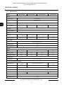
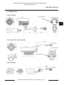
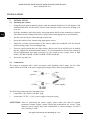
u s e r ’s m a n u a l
NVDN-261H/IR
NVDN-241H/IR
NVDN-221H/IR
NVDN-201H/IR
NVDN-261H/IR, NVDN-241H/IR; NVDN-221H/IR; NVDN-201H/IR
User’s manual ver. 1.0
INFORMATION
EMC (2004/108/EC) and LVD (2006/95/EC ) Directives
CE Marking
Our products are manufactured to comply with the requirements of the following directives and
national regulations implementing the directives:
•
•
Electromagnetic compatibility EMC 2004/108/EC.
Low voltage LVD 2006/95/EC with further amendment. The Directive applies to electrical
equipment designed for use with a voltage rating of between 50VAC and as well as 75VDC
and 1500VDC.
WEEE Directive 2002/96/EC
Information on Disposal for Users of Waste Electrical and Electronic Equipment
This appliance is marked according to the European Directive on Waste Electrical and Electronic
Equipment (2002/96/EC) and further amendments. By ensuring this product is disposed of correctly,
you will help to prevent potential negative consequences for the environment and human health, which
could otherwise be caused by inappropriate waste handling of this product.
The symbol on the product, or the documents accompanying the product, indicates that this appliance
may not be treated as household waste. It shall be handed over to the applicable collection point for
used up electrical and electronic equipment for recycling purpose. For more information about
recycling of this product, please contact your local authorities, your household waste disposal service
or the shop where you purchased the product.
RoHS Directive 2002/95/EC
Out of concern for human health protection and friendly environment, we assure that our products
falling under RoHS Directive regulations, regarding the restriction of the use of hazardous substances
in electrical and electronic equipment, have been designed and manufactured in compliance with the
above mentioned regulations. Simultaneously, we claim that our products have been tested and do not
contain hazardous substances whose exceeding limits could have negative impact on human health or
natural environment.
Information
The device, as a part of professional CCTV system used for surveillance and control, is not designed
for self installation in households by individuals without technical knowledge.
The manufacturer is not responsible for defects and damages that result from improper or inconsistent
with user’s manual installation of the device in the system.
All rights reserved © AAT Holding sp. z o.o.
2
NVDN-261H/IR, NVDN-241H/IR; NVDN-221H/IR; NVDN-201H/IR
User’s manual ver. 1.0
IMPORTANT SAFEGUARDS AND WARNINGS
WARNING!
THE KNOWLEDGE OF THIS MANUAL IS AN INDESPENSIBLE CONDITION OF A
PROPER DEVICE OPERATION. YOU ARE KINDLY REQUSTED TO FAMILIRIZE
YOURSELF WITH THE MANUAL PRIOR TO INSTALLATION AND FURTHER
DEVICE OPERATION.
WARNING!
USER IS NOT ALLOWED TO DISASSEMBLE THE CASING AS THERE ARE NO
USER-SERVICEABLE PARTS INSIDE THIS UNIT. ONLY AUTHORIZED SERVICE
PERSONNEL MAY OPEN THE UNIT
INSTALLATION AND SERVICING SHOULD ONLY BE DONE BY QUALIFIED SERVICE
PERSONNEL AND SHOULD CONFORM TO ALL LOCAL REGULATIONS
WARNING!
PRIOR TO UNDERTAKING ANY ACTION THAT IS NOT DESCRIBED FOR THE GIVEN
PRODUCT IN USER’S MANUAL AND OTHER DOCUMENTS DELIVERED WITH THE
PRODUCT, OR IF IT DOES NOT ARISE FROM THE USUAL APPLICATION OF THE
PRODUCT, MANUFACTURER MUST BE CONTACTED UNDER THE RIGOR OF
EXCLUDING THE MANUFACTURER’S RESPONSIBILITY FOR THE RESULTS OF SUCH AN
ACTION.
IMPORTANT SAFEGUARDS AND WARNINGS
1. Prior to undertaking any action please consult the following manual and read all the safety and
operating instructions before starting the device.
2. Please keep this manual for the lifespan of the device in case referring to the contents of this manual
is necessary;
3. All the safety precautions referred to in this manual should be strictly followed, as they have a
direct influence on user’s safety and durability and reliability of the device;
4. All actions conducted by the servicemen and users must be accomplished in accordance with the
user’s manual;
5. The device should be disconnected from power sources during maintenance procedures;
6. Usage of additional devices and components neither provided nor recommended by the producer
is forbidden;
7. Mounting the device in places where proper ventilation cannot be provided (e. g. closed lockers
etc.) is not recommended since it may lead to heat build-up and damaging the device itself
as a consequence;
8. Mounting the camera on unstable surface or using not recommended mounts is forbidden.
Improperly mounted camera may cause a fatal accident or may be seriously damaged itself. The
camera must be mounted by qualified personnel with proper authorization, in accordance with this
user’s manual;
Wszelkie prawa zastrzeżone © AAT Holding sp. z o.o.
3
NVDN-261H/IR, NVDN-241H/IR; NVDN-221H/IR; NVDN-201H/IR
User’s manual ver. 1.0
IMPORTANT SAFEGUARDS AND WARNINGS
9. Device should be supplied only from a power sources whose parameters are in accordance with
those specified by the producer in the camera technical datasheet. Therefore, it is forbidden to supply
the camera from a power sources with unknown parameters, unstable or not meeting producer’s
requirements;
10. Signal cables (conducting TV or / and telemetric signal) should be placed in a way excluding the
possibility of damaging them by accident. Special attention must be paid to cables getting from the
camera and connecting the power supply;
11. To avoid equipment damage, whole TV circuit should be equipped with properly made
discharge-, overload- and lightning protection devices. Usage of separating transformers is
advised;
12. Electric installation supplying the device should be designed to meet the specifications given
by the producer in such a way that overloading is impossible;
13. User cannot repair or upgrade the equipment himself. All maintenance actions and repairs should
be conducted only by qualified service personnel;
14. Unplug the camera from the power source immediately and contact the proper maintenance
department when the following occurs:
♦ Damages to the power cord or to the plug itself;
♦ Liquids getting inside the device or exposure to strong mechanical shock;
♦ Device behaves in a way not described in the manual and all adjustments approved by the
manufacturer and possible to apply by user himself, seem not to have any effect;
♦ Camera is damaged;
♦ Atypical behaviour of the camera components may be seen (heard).
16. In necessity of repairs attention to using only original replacement parts (with their parameters
in accordance with those specified by the producer) should be paid. Non-licensed service and
non-genuine replacement parts may cause fire or electrocution;
17. After maintenance activities tests should be run to ensure proper operation of all the functional
components of the device.
Attention!
Technical changes reserved without prior notice and printing errors possible.
All rights reserved © AAT Holding sp. z o.o.
4
NVDN-261H/IR, NVDN-241H/IR; NVDN-221H/IR; NVDN-201H/IR
User’s manual ver. 1.0
FOREWORD INFORMATION
1.
FOREWORD INFORMATION
1.1 Package contents
•
Camera with power and video cables
•
Sunshield
•
Bracket
•
User’s manual
•
3 screws, 3 plastic anchors ( 4 screws / 4 anchors in NVDN-261H/IR)
•
Guide pattern
•
Allen key
1.2 Features
•
Mechanical IR cut filter
•
IR operation capability
•
Horizontal resolution: up to 650 TVL in color mode and up to 700 TVL in B/W mode
•
Min.
illumination
from
0.068 lx/F=1.4
NVDN-241H/IR)
(0
lx
IR
on)
(NVDN-261H/IR,
0.089 lx/F=1.6 (0 lx IR on) (NVDN-221H/IR)
0.14 lx/F=2.0 (0 lx IR on) (NVDN-201H/IR)
•
Lens type:
Varifocal f=2.8-11mm (NVDN-261H/IR, NVDN-241H/IR)
Varifocal f= 3.5~8mm (NVDN-221H/IR)
Standard f=3 mm (NVDN-201H/IR);
• 12 VDC +/- 10% power supply
1.3
Overwiev of the cameras and wall brackets
NVDN-221H/IR / NVDN-241H/IR /
NVDN-201H/IR
Horizontal adjustment
NVDN-261H/IR
Vertical adjustment
Counter-screw
Rotation screw
Vertical adjustment
Horizontal adjustment
Stopping ring
Wszelkie prawa zastrzeżone © AAT Holding sp. z o.o.
5
Bracket
NVDN-261H/IR, NVDN-241H/IR; NVDN-221H/IR; NVDN-201H/IR
User’s manual ver. 1.0
SPECIFICATIONS
1.4
Specifications
MODEL
NVDN-261H/IR
NVDN-221H/IR
NVDN-241H/IR
NVDN-201H/IR
IMAGE
1/4" CMOS imager
Pick-up element
Number of Effective
Pixels
720(H) x 576 (V)
Horizontal resolution
650 TVL - color mode, 700 TVL - B/W mode
Min. illumination
0.068 lx/F=1.4
0 lx (IR on)
0.089 lx/F=1.6
0 lx (IR on)
0.068 lx/F=1.4
0 lx (IR on)
0.14 lx/F=2.0
0 lx (IR on)
> 46 dB
S/N Ratio
Auto: 1/50-1/100,000 s
Electronic shutter
LENS
Lens type
Angle of view (H)
Varifocal,
f=2.8 ~ 11 mm/F=1.4
Varifocal,
f=3.5 ~ 8 mm/F=1.6
Varifocal,
f=2.8 ~ 11 mm/F=1.4
Standard ,
f=3 mm/F=2.0
76° ~ 22°
57° ~ 26°
76° ~ 22°
63°
DAY/NIGHT
Mechanical IR cut filter
Type
Switching Mode
Auto
Visible Light Sensor
Yes
IR LED
76
Number
42
24
IR effective range
20 m
25m
20 m
15 m
IR illumination angle
120°
80°
120°
80°
INTERFACES
BNC. 1.0 Vp-p, 75 Ω
Video output
INSTALLATION PARAMETERS
Dimensions (mm)
Weight
162(L) x 100 (W)
x 90 (H)
145(L) x 88 (W) x 83 (H)
102(L) x 62 (W)
x 58 (H)
1,3 kg
830 g
590 g
Aluminium, ivory, fully cable manged bracket in-set included
Enclosure
12 VDC +/- 10%
Power supply
Power consumption
9W
4,5 W
-30ºC ~ 40ºC
Operating temperature
IP 66
Degree of protection
All rights reserved © AAT Holding sp. z o.o.
6
3,5 W
NVDN-261H/IR, NVDN-241H/IR; NVDN-221H/IR; NVDN-201H/IR
User’s manual ver. 1.0
SPECIFICATIONS
1.5. DIMENSIONS
NVDN-261H/IR
Focus adjustment
Zoom adjustment
NVDN-221H/IR / NVDN-241H/IR
Zoom adjustment
Focus adjustment
NVDN-201H/IR
Wszelkie prawa zastrzeżone © AAT Holding sp. z o.o.
7
NVDN-261H/IR, NVDN-241H/IR; NVDN-221H/IR; NVDN-201H/IR
User’s manual ver. 1.0
INSTALLATION
2.
INSTALLATION
2.1
Mounting the camera
•
Using the guide pattern attached, please mark the planned drill holes for wall anchors (and
additional drill hole for the cables). Please ensure that the surface chosen for drilling is an
even one.
•
Drill the mounting (and cable) holes using appropriate drills (when mounting to surfaces
other than concrete ceiling/walls please equip yourself with appropriate screws/anchors)
•
Put the video and power cables through a cable hole.
•
Screw the bracket of the camera using appropriate screws.
•
Adjust the viewing direction/angle of the camera, adjust the sunshield, lock the desired
position using proper screws/stopping rings
•
Unscrew caps located at the rear of the camera, adjust zoom, focus and iris level (in models
that are equipped in aforementioned features). It is recommended to check focus settings in
infrared illumination and make correction in color mode to have proper focus in both
modes. (NVDN-221H/IR, NVDN-261H/IR, NVDN-241H/IR)
Screw the caps back on.
2.2
Connections
The camera is equipped with a video and power cable finishing with 2 plugs, one for video
output, while the second is the power supply plug. Images below show plug polarization.
video
video
ground
+
power supply
- (GND)
The following connecting order should be kept:
•
connect the video cable to the BNC plug
•
connect the 12V DC +/-10% power supply to the power plug
ATTENTION: Prior to connecting the power supply, please make sure that all required
parameters (output voltage, output current and polarization) are correct. Using
improper power supply may cause malfunction or camera damage. In such a
case, warranty is void.
All rights reserved © AAT Holding sp. z o.o.
8
NVDN-261H/IR, NVDN-241H/IR; NVDN-221H/IR; NVDN-201H/IR
User’s manual ver. 1.0
NOTES
Wszelkie prawa zastrzeżone © AAT Holding sp. z o.o.
9
2013-10-02 PR, MM
AAT Holding sp. z o.o., ul. Puławska 431, 02-801 Warszawa, Polska
tel.: 22 546 07 00, faks: 22 546 07 59
www.novuscctv.com


![[ENG] – User Manual – Fun3](http://vs1.manualzilla.com/store/data/005923067_1-4196d0dc74f449cecdfaee0ba5cc5697-150x150.png)