1
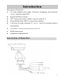
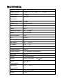
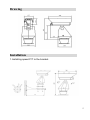
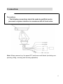
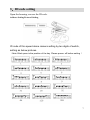
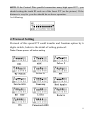
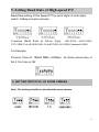
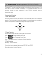
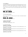
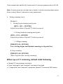
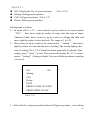
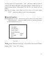
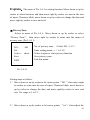
Outdoor High-Speed Pan/Tilt User’s Manual (V4.2) Pleased read the manual carefully before using the product Contents 1. Attention ------------------------------------------------------------------2 2. Introduction --------------------------------------------------------------3 Instruction of Main part ------------------------------------------------4 Specification -------------------------------------------------------------5 Drawing-------------------------------------------------------------------6 Installation----------------------------------------------------------------6 Connection----------------------------------------------------------------7 3. ID code Setting ----------------------------------------------------------8 4. Protocol Setting----------------------------------------------------------9 5. Setting Baud Rate ------------------------------------------------------10 6. Setting Protocol of zoom camera ------------------------------------10 7. Operation----------------------------------------------------------------11 8. Index Diagram of the Screen Menu ---------------------------------15 9. The Menu Setting ------------------------------------------------------18 10. General Failure Analysis Table---------------------------------------26 1 Notes for Attention 1. Read the manual carefully before installing the product. 2. Please do not dismount components inside the product to avoid occurrence of trouble. There is no part inside the product, which needs repair by customer himself. 3. Clean out dirt with special lens tissue if dust is stuck on the lens. 4. Do not aim the camera at the sun or very bright object, aim or monitor bright and still object for a long time whether the power supply of the camera is switched on or off. 5. Do not apply the product under the state exceeding limited temperature, humidity or specifications of power supply. 6. Carefully use camera. Do not shock and strike it. 7. Please install the speed pan/tilt in the wall or horizontal. Do not be bottom up. 8. Observe all electric safety standards in application and adopt special power supply attached the product. RS-485 control signal and video signal should be kept enough distance with the high voltage devices and cables during the course of transmission, and take protection measures such as anti-lightning and surging etc. if necessary. 2 Introduction Description of Functions 10 inches Weather proof design, Dust-proof, antifogging, frost protection function. protection grade IP66 Support OSD Menu function. 360° Continuously rotation, Rotation rate can reach 80◦ /s Horizontal Resolution 480TVL, privacy Zone masking. It will show the angle exactness 0.1◦ by 0.1◦, when the exactness angle is jump phasing. 128 presets. 6 tracks and show preset track No. RS485 serial control Integrated multiple protocols. Instruction of Main Part 3 Specification Effective Pixels 752(H)×582(V) Image Inductor 3.6mm(H)×21.7mm(V) ;1/4inch Video Output 1.0Vp-p Horizontal 480TVL Resolution Signal/Noise Ratio ≥50dB Lowest LUX 1Lux/0.01Lux Iris Auto Focus Auto Focusing Range f4.1-73.8mm Zoom 18×12/27×8 White Balance Auto BLC ON/OFF Panning Range 360°Continuously rotation Pan speed 0.5°~ 80°/s Tilt speed +60°~ -50° Tilt Speed 0.5°~ 60°/s Communication RS485 Preset Position 128 positions in maximum Scanning ON/OFF Tracks 4 cruising tracks Power AC24V /AC220V 70W +10% Power 60W +10% Consumption Operating -30°C~+50°C temperature Size 340×202×448mm(H) Weight 10Kg 4 Drawing Installation 1.Installing speed P/T to the bracket. 5 Connection Precautions • The following connections should be made by qualified service personnel or system installers in accordance with all local codes. Note: When powered up, the speed P/T performs a self-check (including one panning, tilting, zooming and focusing operation). 6 3.ID code setting Open the housing, can see the ID code. Address Setting Protocol Setting ID code of this speed dome camera setting by ten digits of switch, setting as below pictures. (Note: Black pane is the position of the key .Please power- off before setting ) 7 NOTE: If the Control Wire parallel connection many high speed P/T , you should setting the tenth ID code on of the farest P/T (as the picture). If the distance is very far ,you also should do as above operation . As following: 4 Protocol Setting Protocol of this speed P/T could transfer and freedom option by 6 digits switch, below is the detail of setting protocol: Note: Please power- off before setting 8 5. Setting Baud Rate of High-speed P/T Baud Rate setting of this Speed P/T by last 2 digits of sixth digits switch. Setting as below pictures. Common Baud Rate as below (bps): B01/9600; ALEC/4800; VCL/4800; PelcoP/4800/9600; PelcoD/2400; A01/4800; Santanchi/9600. For Example Protocol: Pelco D,Baud Rate: 2400bps,As follow picture Key of No.3, No.5 are in ON 6. SETTING PROTOCOL OF ZOOM CAMERA Note: The setting should be coincident the zoom camera 9 7. OPERATION (Default protocol PELCO-D/2400) The speed P/T can be controlled remotely horizontal and vertical movement. It is used with a system controller, separately. It is controlled remotely from the controller through a serial connection to the RS-485 connector using a twisted-pair cable. Conventional Function 1. Pan / Tilt Function The pan function will move the camera on all horizontal planes, to surveillance position. The tilt function will move the camera on a vertical plane, to surveillance position. The speed is variable according to the angle of joystick. 2. Zoom Function 2.1 The filming range can be set using the zoom function. Press TELE the LCD displays Zoom Tele Press WIDE the LCD displays Zoom Wide Note: the bigger zoom is the slower of joystick speed is. 2.2 Iris Function Normally,Focus is AUTO。 Focus level can be adjusted by pressing [NEAR] and [FAR] Move the joystick, focus will be auto. 10 3. Preset Memory The preset memory function will memories camera positions and zoom, focus, etc. Setting up to 128 preset camera positions can be memorized. Later, you can easily recall any of the preset camera positions by entering its corresponding number, and the camera will move the memorized position with all the preset settings. 3.1 To set a preset position SET + N + ENTER N: the number of preset position: 1~128 3.2 To call a preset position When camera positions have been set, you can enter a memorized camera position number. Preset + N + ENTER N: the number of preset position: 1~128 4. Delete a preset position [PRESET]+[N]+[OFF] N: the number of preset position: 1~128 5. To call cruise tracks: [PRESET]+32+[ENTER] This command can call the No.1cruise tracks. It can scan preset points no.1~16. [PRESET]+53+[ENTER] This command can call the No.2cruise tracks. It can scan preset points no.17~31. [PRESET]+49+[ENTER] This command can call the No.3cruise tracks. It can scan preset points no.33~48. [PRESET]+50+[ENTER] 11 This command can call the No.1cruise tracks. It can scan preset points no.65~80. Note: If some points are not been set or delete, it will not scanning these points when cruising. Resort 3 seconds in every preset point. 6.Setting scanning track Method 1: 1. Setting begin scanning track point [SET] + [51] + [ENTER] Adjust the position of Speed P/T which you need. 2. Setting finished scanning track point: [SET] + [52] + [ENTER] Adjust the position of Speed P/T which you need. 3. Calling scanning: [PRESET]+51+[ENTER] Note: Setting begins and finished scanning track point first. 4. Stop scanning [PRESET]+52+[ENTER] (Move Joystick also can stop scanning) When Speed P/T scanning, default state following a. Speed P/T scan between two points. b. Scan “begin-point” and “end-point” and resort 3 seconds c. If “begin-point” and “end-point” superpose, Speed P/T horizontal 360°rotation. 12 Method 2: Call scanning [AUTO]+[ON] The Speed P/T scanning 360 degree. Need not to set scanning track point. Note: Above operation use for our company’s suited keyboard by example, detail operation do as your keyboard menu 13 The definition of key (N) 54 Control object Power supply PRESET+N+ENTER SET+N+ENTER Come back Initial value / 55 Backlight compensation ON OFF 56 Min. illumination ON OFF ON OFF ON OFF 60 Focus IRIS AUTO AUTO MANUAL MANUAL 61 White Balance AUTO MANUAL 62 Static image Image congeal Normal image 63 Mirror image Image mirror Normal image 64 Color/black & white Color B/W 57 58 59 Menu/ Screen Display Digital Zoom Operation of camera Note: some cameras don’t support the above function of them. Power-off memory Provide setting of scanning track and select scanning track function. Self-test can allow to store track that user edits arbitrarily and information power-off memory. 8. Index Diagram of the Screen Menu 14 This is the camera’s OSD function, which include the menu while opening and the menu while operating. Open it, and see the start of image, the order of showing is: Waiting for image 15 Waiting… The image of system information Version: 1.02 Camera: Sony Dome ID: 001 Protocol: Pelco D Band Rate: 2400 The information of checking itself 16 Horizontal Check OK Vertical Check OK Camera Check OK The finished information of checking itself It’s passed start to operate the speed P/T 17 The Menu Setting ● The major menu setting After checking itself, please PRESET+8+ENTER, then it will show the image as the No.1-0-1: System Info System Setup Camera Control Preset Control Special Function Factory Default →(Pic.1-1-1) →(Pic.1-2-1) →(Pic.1-3-1) →(Pic.1-4-1) →(Pic.1-5-1) EXIT 1-0-1 System information On the menu of 1-0-1, turn up or down the rocker to point to system info (or click the up or down key of controlling system), then turn right to enter to system info (or click the right key of control system) As per the image 1-1-1: Version: 1.02 Camera: Sony Dome ID: 001 Protocol: Pelco D Baud Rate: 2400 EXIT Pic.1-1-1 The last pages all show the system settings; the consumer can’t operate any 18 item of setting the function of system. ● System setting No this function. ●.Camera function setting On the image 1-0-1, turn up or down the rocker to point to the camera control,then turn right to enter to the function menu of camera. Back Light: OFF Digital Zoom: OFF Focus Mode: AUTO IRIS Adjust: AUTO White Balance: AUTO Image Freeze: OFF Next EXIT Pic. 1-2-1 Remark:The menu of this page is to set the function of integration camera. ◆ Black Light:to set back light,default “OFF”,choose “ON” if you need. ◆ Digital Zoom:to set digital zoom, default ”OFF”,choose ”ON” if you need; ◆ Focus Mode:to set focus mode,default ”AUTO”,choose “MANU” if you need; ◆ IRIS Adjust to set iris adjust ,default ”AUTO”,choose “MANU” if you 19 need; ◆ White Balance:to set the model of white balance , show ”AUTO”, choose “MANU” if you need; ◆ Image Freeze: to set the switch of image freeze,default “OFF”,choose “ON” if you need; ◆ Next: enter to next menu of function The step is as following: 1) Turn up or down the rocker to point to the choice item, and then turn right to enter to input area. Turn up or down the rocker to amend the input value while the on/off is flashing; 2) Set the rest item as step 1; 3) All finished , turn up or down the rocker to point to exit, then turn right the rocker and exit if it point to next ,turn right and enter to next image, it will show as Pic.1-2-2: Image Reverse: OFF Color Video: ON AGC Adjust: AUTO Brightness Adjust: AUTO Zoom Speed: 7 Focus Speed: 7 Reset EXIT Pic.1-2-2 20 Note:This menu is to set the remind information of screen showing (Pic.1-2-2) ◆ Image Reverse:Default OFF,select ON; ◆ Color Video: Default setting ON(Color) ,select OFF(BW). ◆ AGC Adjust:Default AUTO ◆ Brightness Adjust:Default AUTO; ◆ Zoom Speed:Default 7; ◆ Focus Speed: Default 7; ◆ Reset: Select this setting , Come back initial producer setting Steps of setting same as above setting: Note:Maybe some cameras have no full functions of above menu. Please according to actual functions set camera. ● Setting Preset Position The menu of Pic. 1-0-1,move down or up by rocker to let cursor points “Preset Control”,then move right by rocker to come into menu of setting preset position(Pic.1-3-1): NO. : Setting Call Delete EXIT 001 Pic. 1-3-1 Explain:Above menu is used to set, call and delete preset positions. 21 (Pic.1-3-1) : ◆ NO.: Display the No. of preset position. ◆ Setting: Setting preset position ◆ Call: Call preset position(Pic.1-3-2) (No.:1-128) ; ◆ Delete: Delete preset position Setting steps as follow: 1) In menu of Pic. 1-3-1,move down or up by rocker to let cursor points “NO.”, then move right by rocker to come into the area of input. Character blink, move down or up by rocker to change the data and move right by rocker to save and exit. No. range is 1 to 128. 2) Move down or up by rocker to let cursor points “setting”, then move right by rocker to come into the area of setting. The screen displays the state of setting (Pic.1-3-2).Control the dome camera by keyboard. After setting, press“close”to save. The screen will display Pic.1-3-1, cursor points “setting”, Setting is finish. You can call this position to confirm it is saved. NO: 001 Setting Call Delete EXIT PRESS CLOSE TO SAVE PRESS OPEN TO ESC Pic.1-3-2 3)Select the No. of preset position before Call preset position,move down 22 or up by rocker to let cursor points “call”, then move right by rocker to confirm, the camera will adjust to the preset position(Note: If the No. of preset position haven’t been settled. Call this No. the camera will not adjust.) 4) After all setting,move down or up by rocker to let cursor points “EXIT”, then move right by rocker to exit setting menu ●. Special Function 5) In menu of Pic. 1-0-1,move down or up by rocker to let cursor points “Special Function”, then move right by rocker to come into the menu of special function (Pic.1-4-1). Auto Mode Auto Running Privacy Zone Motion Detection Brush : NONE Day/night : OFF Exit Pic.1-4-1 Note:Brush(Function of rain strip):If system have this function, Default display“OFF” ;Elect “ON” (Using). 23 Explain:The menu of Pic.1-4-1 is setting function. Move down or up by rocker to select function, and then move right by rocker to come in the area of input. Character blink, move down or up by rocker to change the data and move right by rocker to save and exit. ●.Privacy Zone Select in menu of Pic.1-4-1,Move down or up by rocker to select “Privacy Zone”, then move right by rocker to come into the menu of privacy zone (Pic.1-4-11). NO : 001 Set Active : show Save EXIT No. of privacy zone, (Select NO.: 1-12). Enter setting menu.→(1-4-11) Select to open or close privacy function. Save privacy zone. Exit this menu. Pic.1-4-11 Setting steps as follow: 1) Move down or up by rocker to let cursor points “NO.”, then move right by rocker to come into the area of input. Character blink, move down or up by rocker to change the data, and move right by rocker to save and exit. No. range is 1 to 12. 2) Move down or up by rocker to let cursor points “set” ,then adjust the 24 cover positions and press“Close”to save and exit, next set up adjust the range of privacy and press “Close” to save and exit. 3) If “Active ON” can setting above steps.; 4)Move down or up by rocker to let cursor points “Save”to save privacy zone. Note:After setting privacy zone must save it. If not the speed P/T will be not memory. 5. Recovery Function In menu of Pic. 1-0-1,Move down or up by rocker to let cursor points “Factory Default”, then move right by rocker to come into the menu of recovery function (Pic.1-5-1). FACTORY NO DEFAULT? YES Pic. 1-5-1 Explain:Pic.1-5-1,There is a reminder that is recovery factory setting or not. Default setting is NO. If recovery factory setting, you can Move down or up by rocker to choose“YES”, then move right by rocker to confirm it. After 5 seconds, automatically return main menu. ●Exit the Screen Menu After setting, SET+8+ENTER, exit the screen menu. General Failure Analysis Table 25 Problem Description After power on, no motion and no image Self test is exceptional, there is image but with motor noise “wu” Possible Reason Power supply module is damaged or power is not enough. Change Power cable is connected improperly Correct Failure occurs on engineering line. Eliminate Mechanical failure Examine and Repair Video camera is slantwise Put right Power supply not enough Video line is connected mistakenly. Self-test is normal, but have no image Self-check ok but cannot control Troubleshooting Change power that meets requirements. It is recommended to place the power switch near the Speed P/T. Correct Video line is poor contact. Eliminate Video camera is damaged. Change Control signal line is connected mistakenly. Correct Position of Speed P/T does not match. Protocol setting is wrong Reselect Reset and on power again Video line is poor contact. Eliminate Power supply not enough Change Vague image Too much load or communication distance is too long. P/T is not controllable. Confirm terminal resistance Add code distributor Self-test is exceptional On power again Bad connection of control Press to full connect Operation of Host has problem. On power again RS485 and Terminal resistance When communication of RS485 connected by star type, If use 120Ωresistor to connect the two fairest equipments. It will not fit for the RS485 Industrial standard. It’s easy to be out of control. So advise to use RS485 code drivers. 26