1
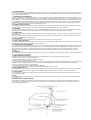
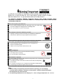
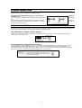
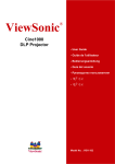
32” HD Ready LCD TV
DGL32
User’s Manual
WARNING: TO PREVENT FIRE OR SHOCK HAZARD, DO NOT EXPOSE THIS APPLIANCE TO RAIN OR
MOISTURE.
WARNING:
This equipment has been tested and found to comply with the limits for a Class B digital device, pursuant to Part 15 of the FCC
Rules. These limits are designed to provide reasonable protection against harmful interference in a residential installation. This
equipment generates, uses and can radiate radio frequency energy and, if not installed and used in accordance with the
instructions, may cause harmful interference to radio communications.
However, there is no guarantee that interference will not occur in a particular installation. If this equipment does cause harmful
interference to radio or television reception, which can be determined by turning the equipment off and on, the user is
encouraged to try to correct the interference by one or more of the following measures:
- Reorient or relocate the receiving antenna.
- Increase the separation between the equipment and receiver.
- Connect the equipment into an outlet on a circuit different from that to which the receiver is connected.
- Consult the dealer or an experienced radio/TV technician for help.
CAUTION:
Changes or modifications not expressly approved by the party responsible for compliance with the FCC Rules could void the
user's authority to operate this equipment.
IMPORTANT SAFEGUARDS
1. READ INSTRUCTIONS
All the safety and operating instructions should be read before the unit is operated.
2. RETAIN INSTRUCTIONS
The safety and operating instructions should be retained for future reference.
3. HEED WARNINGS
All warnings on the unit and in the operating instructions should be adhered to.
4. FOLLOW INSTRUCTIONS
All operating and use instructions should be followed.
5. CLEANING
Unplug this unit from the wall outlet before cleaning. Do not use liquid cleaners or aerosol cleaners. Use a damp cloth for cleaning the
exterior cabinet only.
6. ATTACHMENTS
The manufacturer of this unit does not make any recommendations for attachments, as they may cause hazards.
7. WATER AND MOISTURE
Do not use this unit near water. For example, near a bathtub, washbowl, kitchen sink, laundry tub, in a wet basement, or near a swimming
pool.
8. ACCESSORIES
Do not place this unit on an unstable cart, stand, tripod, bracket, or table. The unit may fall, causing serious injury, and serious damage to
the unit.
8A. An appliance and cart combination should be moved with care. Quick stops, excessive force, and uneven surfaces may cause the
appliance and cart combination to overturn.
9. VENTILATION
Slots and openings in the cabinet back or bottom are provided for ventilation, and to ensure
reliable operation of the unit, and to protect it from overheating. These openings must not be
blocked or covered. The openings should never be blocked by placing the unit on a bed, sofa, rug,
or other similar surface. This unit should never be placed near or over a radiator or heat source.
This unit should not be placed in a built-in installation such as a bookcase or rack unless proper
ventilation is provided or the manufacturer’s instructions have been adhered to.
1
10. POWER SOURCES
This unit should be operated only from the type of power source indicated on the rating plate. If you are not sure of the type of power supply
to your home, consult your appliance dealer or local power company. For units intended to operate from battery power, or other sources,
refer to the operating instructions.
11. GROUNDING OR POLARIZATION
This unit is equipped with a polarized alternating current line plug (a plug having one blade wider than the other). This plug will fit into the
power outlet only one way. This is a safety feature. If you are unable to insert the plug fully into the outlet, try reversing the plug. If the plug
should still fail to fit, contact your electrician to replace your obsolete outlet. Do not defeat the safety purpose of the polarized plug, if your
unit is equipped with a 3-wire grounding-type plug, a plug having a third (grounding) pin. This plug will only fit into a grounding-type power
outlet. This too, is a safety feature. If you are unable to insert the plug into the outlet, contact your electrician to replace your obsolete
outlet. Do not defeat the safety purpose of the grounding type plug.
12. POWER-CORD PROTECTION
Power-supply cords should be routed so that they are not likely to be walked on or pinched by items placed upon or against them, paying
particular attention to cords at plugs, convenience receptacles, and the point where they exit from the appliance.
13. LIGHTNING
To protect your unit from a lightning storm, or when it is left unattended and unused for long periods of time, unplug it from the wall outlet
and disconnect the antenna or cable system. This will prevent damage to the unit due to lightning and power line surges.
14. POWER LINES
An outside antenna system should not be located in the vicinity of overhead power lines or other electric light or power circuits, or where it
can fall into such
power lines or circuits. When installing an outside antenna system, extreme care should be taken to keep from touching such power lines
or circuits, as contact with them might be fatal.
15. OVERLOADING
Do not overload wall outlets and extension cords, as this can result in a risk of fire or electric shock.
16. OBJECT AND LIQUID ENTRY
Do not push objects through any openings in this unit, as they may touch dangerous voltage points or short out parts that could result in fire
or electric shock. Never spill or spray any type of liquid into the unit.
17. OUTDOOR ANTENNA GROUNDING
If an outside antenna or cable system is connected to the unit, be sure the antenna or cable system is grounded to provide some protection
against voltage surges and built-up static charges, Section 810 of the National Electrical Code, ANSI/NFPA 70, provides information with
respect to proper grounding of the mast and supporting structure, grounding of the lead-in wire to an antenna discharge unit, size of
grounding conductors, location of antenna discharge unit, connection to grounding electrodes, and requirements for the grounding
electrode.
18. SERVICING
Do not attempt to service this unit yourself as opening or removing covers may expose you to dangerous voltage or other hazards. Refer all
servicing to qualified service personnel.
19. DAMAGE REQUIRING SERVICE
Unplug this unit from the wall outlet and refer servicing to qualified service personnel under the following conditions:
a. When the power-supply cord or plug is damaged.
b. If liquid has been spilled, or objects have fallen into the unit.
c. If the unit has been exposed to rain or water.
d. If the unit does not operate normally by following the operating instructions. Adjust only those controls that are covered by the operating
instructions, as an improper adjustment of other controls may result in damage and will often require extensive work by a qualified
technician to restore the unit to its normal operation.
e. If the unit has been dropped or the cabinet has been damaged.
f. When the unit exhibits a distinct change in performance, this indicates a need for service.
20. REPLACEMENT PARTS
When replacement parts are required, be sure the service technician uses replacement parts specified by the manufacturer or those that
have the same characteristics as the original part. Unauthorized substitutions may result in fire, electric shock or other hazards.
21. SAFETY CHECK
Upon completion of any service or repairs to this unit, ask the service technician to perform safety checks to determine that the unit is in
proper operating condition.
22. HEAT
The product should be situated away from heat sources such as radiators, heat registers, stoves, or other products (including amplifiers)
that produce heat.
23. NOTE TO CATV SYSTEM INSTALLER
This reminder is provided to call the CATV system installer’s attention to Article 820-40 of the NEC that provides guidelines for proper
grounding and, in particular, specifies that the cable ground shall be connected to the grounding system of the building, as close to the
point of cable entry as practical.
2
TO PREVENT POSSIBLE DANGER, ELECTRIC SHOCK, AND OTHER INJURIES WHEN
HANDLING YOUR DISPLAY, PLEASE BE AWARE ALL WARNINGS AND SAFETY PRECAUTIONS
CONTAINED AS BELOW.
Never Insert anything into DISPLAY!!
Do not insert anything through the openings in the unit, where they
can touch dangerous voltage points or damage parts.
Never spill liquid of any kind on the Display。
Do not attempt to service the DISPLAY yourself!!
Opening or removing covers may expose you to dangerous voltages and
other hazards. Refer all servicing to qualified service personnel.
Do not touch your DISPLAY and antenna during thunderstorms!!
Unplug the Display during thunderstorms or if it is not going to be
used for an extended period.
Failure to do so may result in electric shock or fire.
ATTENTION!!
Unplug the DISPLAY from the wall socket before cleaning.
Use a damp cloth for cleaning.
Do not use liquid or aerosol cleaners.
Well ventilation is required!!
To ensure reliable operation of the product and to protect it from overheating, the ventilation
must not be blocked or covered.
The display should be no less than 4 inches from the wall, and always keep
the vent clean.
Do not place your DISPLAY in a cramped and inadequately ventilated place.
Avoid placing your DISPLAY upside down at any time.
Note:
1. Read all safety and operating instructions before operating your new Display.
To ensure good ventilation, a distance of more than 4” shall be maintained between
the Display and any other furniture.
2. The operating temperature for this Display is 5 ~ 35 °C, storage temperature is 0 ~ 60 °C。
3
CONFORMITY AND COMPLIANCE
FCC Compliance Statement
This equipment has been tested and found to comply with the limits for a Class B digital device, pursuant
to Part 15 of the FCC Rules. These limits are designed to provide reasonable protection against harmful
interference when the equipment is operated in a residential installation. This device generates, uses, and
can radiate radio frequency energy and, if not installed and used in accordance with the instructions, may
cause harmful interference to radio communications. However, there is no guarantee that interference will
not occur in a particular installation. If this device does cause harmful interference to radio or television
reception (this can be determined by turning, the device off and on), you are encouraged to try to correct
the interference by one or more of the following measures:
*Reorient or relocate the receiving antenna.
*Increase the separation between the equipment and the receiver.
*Connect the equipment into an outlet on a circuit different from that to which the receiver is
connected.
*Consult the dealer or an experienced radio/TV technician for help.
Caution:
To comply with the limits for an FCC Class B computing device, you should use the shielded signal cord
and power cord supplied with this unit. The Federal Communication Commission warns that changes or
modifications of the unit not expressly approved by the party responsible for compliance could void the
user’s authority to operate the equipment.
Radio Frequency Interference Statement
Warning:
This is a Class B product. In a domestic environment this product may cause radio interference in which
case the user may be required to take adequate measures.
Canadian Doc Notice
For Class B Computing Devices
This digital apparatus does not exceed the Class B limits for radio noise emissions from digital apparatus
as set out in the Radio Interference Regulation of the Canadian Department of Communications.
CE MARKING DECLARATION OF CONFORMITY
The LCD display complies with the requirements of related European standards, which include:
Emission: EN 55022, EN 61000-3-2, EN-61000-3-3
Immunity: EN 50082-1
Safety: EN 60950 Low-Voltage Directive (73/23/EEC)
manufactured
under license from BBE Sound, Inc.
is a trademark
of SRS Labs, Inc. WOW technology is
incorporated under license from SRS Labs,
Inc.
4
Table of contents
Introduction
Congratulations on the purchase of your LCD TV. This handbook has been designed to
help you install and operate your display. We would recommend reading it thoroughly.
Table of contents
Page
Getting Start
Features………………………………………………………….
Standard Accessories………………………………………….
Location of Controls.…………………….………………….……
Remote Control…………………………………………………..
6
6
8
10
Installation
Installing your Display…………...……………………………..
SET UP………..……………………………………………….…
12
13
Operation - TV
Basic operation………………………………………………….
OSD menu setting …………………….………………….……
TV/PC parameters……..……...……………………………..
Audio settings……………………………………………….…
Picture-in-picture………..………………………………….…
General settings………………………………………….……
Parental controls …………………..…..………………….…
14
15
16
17
18
19
21
Other information
Troubleshooting ………………………….…………………..
Supported operation mode ……………….…………………
Introduction
5
24
25
Getting Start
FFeeaattuurreess
․ Support WXGA resolution up to 1366x768 pixels
․ Wide viewing angle
․ VESA DPMS-compliant power saving: automatically powers down the monitor after a
defined period of inactivity
․ Digital Character Smoothing
․ Analog TV tuner
․ Windows 95/98/2000/XP Plug & Play Compliant
․ Versatile, User friendly OSD
․ Plug & Play: Conform to the VESA standards and support DDC 2B spec.
S
Sttaannddaarrdd A
Acccceessssoorriieess
Unpacking and Checking Package Contents
Before unpacking your LCD Display, prepare a stable, level, and clean surface near
a wall outlet for your LCD Display.
Set the LCD Display box in an upright position and open from the top of the box
before removing the top cushion.
Accessories
1 pc
User’s Manual
1 pc
VGA Cable
1 pc
Remote
Controller
1 pair
Batteries
1 pc
Power Cord
1 pc
Audio Cable
Power source required:
AC 100 ~ 240 V (3.5A), 50 / 60 Hz
6
1 pc
Antenna
Adapter
ANTENNA CONNECTIONS
If you are using an indoor or outdoor antenna, follow the instructions below that correspond to your antenna system. If you are
using a cable TV (CATV) see “CABLE TV CONNECTIONS”.
Combination VHF/UHF Antenna (Single 75 Ohm cable or
twin-lead wire)
300 Ohm
Connect the 75 Ohm cable from the combination VHF/UHF antenna to
Jack.
If your combination VHF/UHF antenna has a 300 Ohm twin-lead wire,
the 300-75 Ohm Matching Transformer may be necessary. Connect
Ohms cable and UHF 300 Ohm.
the Antenna
the use of
the VHF 75
CABLE TV CONNECTIONS
This TV has an extended tuning range and can tune most cable channels without using a Cable TV converter box. Some cable
companies offer “premium pay channels” in which the signal is scrambled. Descrambling these signals for normal viewing requires
the use of a descrambler device which is generally provided by the cable company.
FOR SUBSCRIBERS TO BASIC CABLE TV SERVICE
For basic cable service not requiring a Converter Descrambler box, connect the CATV 75 Ohm Coaxial Cable directly to the
Antenna Jack on the side of the TV.
FOR SUBSCRIBERS TO SCRAMBLED CABLE TV SERVICE
If you subscribe to a cable TV service which requires the use of a Converter/Descrambler box, connect the incoming 75 Ohm
Coaxial Cable to the Converter/Descrambler box. Using another 75 Ohm coaxial cable, connect the output jack of the
Converter/Descrambler box to the Antenna Jack on the TV. Set the TV to the output channel of the Converter/Descrambler box
(usually channel 3 or 4) and use the Converter/Descrambler box to select channels.
7
Getting Start
Front View
LLooccaattiioonn ooff C
Coonnttrroollss
Operating the monitor
Multicolor LED indicator illuminates in
Green for operating PC monitor and
TV system, Red when Power plug in
(Standby).
Front Panel Buttons:
① POWER:Press to active the Display On and Off (Standby).
② SOURCE:Press to display all of the available input sources.
③ MENU:Press to see OSD menu of your TV’s adjustments / selections.
④ ENTER: Press to confirm selection / adjustment.
⑤,⑥ CHd/c: Press to select the channel or select items in OSD menu.
⑦,⑧ VOLf/e:Press to adjust the volume, select OSD items and adjust the menu items.
9 MAIN POWER SWITCH (Rear Panel): Set to on ( ━ ) to power up unit.
8
Getting Started
Rear View
REAR PANEL JACKS
Side View
1
Y1Cb1Cr1
Connecting to the Video component1 output terminal of the video output device.
2
Y1Cb1Cr1 Audio
Audio input terminal connecting to the audio output terminal of the video output device.
3
Y2Pb2Pr2
Connecting to the Video component2 output terminal of the video output device.
4
Y2Pb2Pr2 Audio
Audio input terminal connecting to the audio output terminal of the video output device.
5
S-video
Y/C S-video input terminal connecting to the S-output terminal of the video output device.
6
S-video Audio
Audio input terminal connecting to the audio output terminal of the video output device.
7
Sub-woofer
8
Video out
9
Audio out
10 AV 1 in
Connects the sub-woofer audio.
Video output terminal connecting to the input terminal of the video input device.
(The video output sources are only AV1, AV2, AV3 and TV)
Audio output terminal connecting to the input terminal of the audio input device.
(The audio output sources are AV1, AV2, AV3 and TV)
To connect the AV1 source.
11 AV 1 audio in
To connect the audio out of AV1 source.
12 AV 2 in
To connect the AV2 source.
13 AV 2 audio in
To connect the audio out of AV2 source.
14 AV 3 audio in
To connect the audio out of AV3 source.
15 AV 3 in
To connect the AV3 source.
16 Headphone
To connect to headphone.
Bottom view
1
PC Audio
Connect this terminal to the sound output terminal of your PC or Notebook.
2
ANT
Connect the coaxial cable or antenna.
3
D-sub
Connects to D-sub 15 pin analog output connector of the PC display card.
4
DVI for PC
Connects to DVI digital output connector of the PC display card.
5
AC in
Connect this terminal to the power cord supplied with Display, and a switch is attached
to turn on /off the power of unit.
DVD
CAM
GAME
ANT
Using ANT.
Adapter
included
Connect the
cable or
antenna
Connect the
power supply
Audio cable connects to PC audio
VGA cable connects to VGA card.
DVI cable connects to DVI card (if DVI cable is available)
9
Use Y1Cb1Cr1/Y2Pb2Pr2,
AV, or S-video to connect
the VCR, DVD or the Video
Game.
Getting Start
R
Reem
moottee C
Coonnttrrooll
TV Function
1
2
POWER
TV
3
SOURCE
4
5
6
7
8
9
10
11
12
13
14
15
16
17
18
19
20
21
22
23
24
Number keys
DISPLAY
MUTE
MTS
SOUND
PICTURE
SLEEP
Enter
Recall
MENU
CH d/c
ZOOM
VOLe/f
PIP
Source
Position
Freeze
Swap
ENTER
C.C.
V-Chip
Power On/Off
Switch source to TV mode.
Select main input source: TV VGA
AV3
DVI S-VIDEO
COMPONENT 1 COMPONENT 2
AV1 AV2
Select channel by numbers.
Display current information.
Turn speaker On or Off.
Select the TV audio mode: MONO-> STEREO-> SAP.
Select the sound mode: Off-> SRS WOW-> BBE
Adjust display color: Soft->Standard->Cool->Define
Set the Timer to turn off the set. (OFF, 10, 20, 30, 60, 90, 120 Min)
Confirms the channel after you select channel by number.
Return to previous channel.
Press to enter OSD menu.
Select channel.
Resize from 4:3 to Full screen or Full to 4:3 screen.
Control the volume Up or Down.
Select the PIP function.
Select the sub-screen’s source.
Adjust the PIP position.
Freeze the PIP main screen.
Switch the picture of main screen to sub-screen.
Confirm the adjustment or the selected item.
Turn C.C. function On and Off. (U.S. area only)
Turn V-Chip mode On and Off. (U.S. area only)
10
REMOTE CONTROL
BATTERY INSTALLATION
Slide the battery compartment cover.
Install two “AAA” batteries (supplied), paying close attention to the + / - polarity diagram in the battery compartment.
Replace the compartment cover.
BATTERY PRECAUTIONS
The precautions below should be followed when using batteries in this device:
1 Use only the size and type of batteries specified.
2 Be sure to follow the correct polarity when installing the batteries as indicated in the battery compartment. Reversed batteries may cause
damage to the device.
3 Do not mix different types of batteries together (e.g. Alkaline and Carbon-zinc) or old batteries with fresh ones.
4 If the device is not to be used for a long period of time, remove the batteries to prevent damage or injury from possible battery leakage.
5 Do not try to recharge batteries not intended to be recharged; they can overheat and rupture (Follow battery manufacturer’s directions).
NOTES:
• When there is an obstacle between the TV and the remote control, the remote control may not operate.
• When direct sunlight, an incandescent lamp, fluorescent lamp or any other strong light shines on the Remote sensor of the TV, the remote
operation may be unstable.
POWER SOURCE
Use the AC line cord provided for operation on AC. Insert the AC cord plug into a
standard 120V 60Hz grounded AC outlet.
NOTES:
• Never connect the AC line cord plug to anything other than the specified voltage
(120V 60Hz). Use the attached power cord only. • If the polarized AC cord does not
fit into a grounded non polarized AC outlet, do not attempt to file or cut the blade. It
is the user's responsibility to have an electrician replace the obsolete outlet.
11
Installation
IInnssttaallliinngg yyoouurr D
Diissppllaayy
Step 1. Positioning the display set
Place your Display set on a solid stable surface.
Do not expose the display to water, or a heat
source. Do not obstruct the ventilation grid at rear.
ANT
Step 2. Connecting the aerials (Antenna)
1. Use the antenna adapter (included) to connect the
Cable / Antenna to TV tuner socket situated at the side
of the TV.
2. Connect the cable to TV.
① Tuner Adapter
② Aerial / Antenna cable
Step 3. Power supply connections
Insert the power cord plug into the wall socket. And then
turn on the power switch.
Step 4. Remote control
Insert the two AAA/UM4-type batteries
supplied, making sure the +/- polarities are
properly aligned.
12
Installation
S
SE
ETT U
UP
P
If TV is connected to an antenna, you’ll need to set a few important items in the
menu system the first time you turn on your Display.
Auto scan:
This part of the setup allows the TV tuner to search for all channels viewable though
your antenna or cable TV system (when there is no cable box connected).
Press “MENU” on Remote or TV’s front panel to
view OSD- “TV Parameters”.
Pressf button 3 times to highlight the fifth item
“Channel Settings”.
Press “ENTER” to select “SYSTEM” and select
system (Antenna/Cable), then confirm with
“ENTER”.
Select “AUTO SCAN” and select “YES” to begin
the auto channel search.
(Press “MENU” at anytime to stop auto scan
function)
Ch. Edit (Channel Edit):
While in the “CHANNEL SETTINGS” select “CH. EDIT” to add additional receivable
channels and erase unwanted channels during Up/Down tuning.
13
Operation - TV
B
Baassiicc O
Oppeerraattiioonn
Power On/Off
Press the “POWER” key to turn ON the Display. The power indicator changes from
red to green. When the power is OFF (stand by), the power indicator changes from
green to red.
Source select
Press “SOURCE” button to select the input signal. Each time the source button is
pressed, the on-screen display will cycle between:
TV
Component2 (Y2Pb2Pr2)
VGA
DVI
S-VIDEO
Component1 (Y1Cb1Cr1)
AV1
AV3
AV2
TV Button
Press TV button to directly switch to TV mode without using the source key to select.
Adjusting the volume
Press f on the remote controller or front panel to increase the volume.
Press e to decrease the volume.
Channel select
Press c on the remote controller or front panel to change to the next channel.
Press d to change to the previous channel or you can select a channel number and
press “Enter” select to the select channel directly.
Menu On/Off
Press “MENU” key to display the menu (OSD) On/Off.
Use d/c to select the item on the main menu.
Press “ENTER” to select the submenu and press e/f to adjust the setting.
14
Operation - TV
O
OS
SD
DM
ME
EN
NU
UD
DE
ES
SC
CR
RIIP
PTTIIO
ON
N
To access MENU navigate and make adjustments, use MENU, cCH, dCH, eVOL,
f VOL and ENTER.
Pressing “MENU” display and the OSD menu. Use cCH / dCH on the remote
controller to scroll the options on the menu.
Press “ENTER” button to enter sub menu.
Usee/f to adjust settings.
Press “ENTER” to confirm desired settings.
Press “MENU” to exit the current OSD menu.
Main Menu:
There are seven SUB-MENUS in the main OSD Menu;
1.TV PARAMETERS; 2.PC PARAMETERS; 3.AUDIO SETTINGS; 4.Picture-In-Picture;
5.CHANNEL SETTINGS; 6.PARENTAL CONTROLS; 7.GENERAL SETTINGS.
In TV mode – Press MENU
Use e/f buttons to select: TV Parameters, Audio setting, Picture-In-Picture, Channel
settings, Parental controls, and General settings.
Note: In TV mode, “PC Parameters” can not be selected.
In Video mode (S-VIDEO, AV1 ,AV2, AV3, COMPONENT1(Y1Cb1Cr1) ,
COMPONENT2(Y2Pb2Pr2))
Press “MENU” button, Main menu will be displayed on the screen (see figure above).
Use e/f buttons to select the submenu: TV Parameters, Audio setting, Picture-InPicture, and General Settings.
Note: 1. In this mode, “Channel settings” can not be selected.
2. For devices with 480p, 720p or 1080i output, please connect them to
Component2 jacks to get the ideal resolution and picture quality.
In PC mode (DVI, VGA)
Press “MENU” button, Main menu will be displayed on the screen (see figure above).
Use e/f buttons to select the submenu: Audio settings, Picture-In-Picture and General
settings.
Note: In this mode, “TV Parameters” and “Channel settings” can not be selected.
15
Operation - TV
TTV
V//P
PC
CP
Paarraam
meetteerrss
TV Parameters
Press “MENU” and make sure “TV Parameters” appears on the screen.
Adjusting the TV setting:
Brightness: Alters the brightness of the image.
Contrast: Alters the ratio of light to darkness.
Sharpness: Adjusts the sharpness of the color.
Saturation: Alters the color saturation.
Hue: Alters the color intensity.
Color temp: Adjusts the color temperature of the
picture. Three options are available here: 6500, 7500,
9300, and USERS.
Format: Two options are available here: Full screen
(16:9), and 4:3.
16:9
4:3
Color Temp.
PC parameters
Adjusting the picture setting:
Set Image:
Brightness: Alters the brightness of the image.
Contrast: Alters the variation between light and
darkness.
Auto: Auto adjusts the position of the image.
Auto color: Auto adjusts the color balance.
Note: “AUTO COLOR” function is only available in
“VGA” and “Component 2” input sources. By accessing
“ALL RESET” function in “General Settings” , the color
will return to the factory default setting.
Clock: Adjusts the clock frequency.
Phase: Adjusts the phase frequency.
H-Position & V-Position: Adjusts the horizontal and
the vertical position of the image.
Color Temp.: Adjusts the color temperature of the
picture.
Format: Two options are available here: Full screen
(16: 9), and 4:3.
16
Operation - TV
A
Auuddiioo S
Seettttiinnggss
Press “MENU” and pressf to make sure the “AUDIO SETTINGS” is displayed on the
screen.
In TV, Video, and PC modes
Adjusting the audio setting:
MTS (For TV mode only):
Volume: This will adjust the level of volume.
Mute: Mutes the sound
Bass: This will adjust the level of low frequency
content in the sound. (enabled only for BBE or
SRS WOW feature is off)
Treble: This will adjust the level of high
frequency content in the sound. (enabled only for
BBE or SRS WOW feature is off)
Balance: This will adjust the output of the R/L
speakers to obtain the best stereo reproduction.
MTS: This will select the TV audio system. Three
options available: Mono, Stereo, SAP.
Surround: This will select the modes for SRS
WOW sound effect.
BBE: This can improve clarity of sound and
speech Legibility.
17
Operation - TV
P
Piiccttuurree--IInn--P
Piiccttuurree
PIP function:
With PIP function you can watch a multi-screen on the Display at the same time.
PIP
SOURCE
POSITION
SWAP
Freeze
To start the PIP function.
Off->PIP(Small) ->PIP(Medium) ->PIP(Large)-> PBP -> POP
To select the sub screen’s source. (see the PIP structure below)
To adjust the PIP position.
To switch the picture of main screen to sub screen.
To freeze the PIP main screen.
[Basic function]
You can control PIP function easily by remote control.
PIP mode
PIP source
PIP position
POP
PIP size –small
Source & swap
Swap PIP
PBP
source & swap
PIP size–medium PIP size–large
Freeze the PIP
main screen
Note: 1. M: main screen; S: sub-screen
2. The submenu of PIP position can be used to control the position of sub-screen.
3. The control of “SOURCE” for sub-screen, “SWAP”, and “FREEZE” for main-screen
can be enabled via the key- “SOURCE”, “SWAP” and “FREEZE” separately.
PIP structure
PIP
SubScreen
TV
AV1
AV2
Main Screen
S-Video
Component1
(Y1Cb1Cr1)
AV3
TV
AV1
AV2
AV3
S-Video
Component1
(Y1Cb1Cr1)
Component2
(Y2Pb2Pr2)
VGA
DVI
18
Component2
(Y2Pb2Pr2)
VGA
DVI
Operation - TV
G
Geenneerraall S
Seettttiinnggss
Press “MENU” and pressf to make sure “GENERAL SETTINGS” appears on the
screen.
In TV, Video, and PC modes
Adjusting the general setting:
OSD Timeout: Adjusts the OSD disappearing time
without taking any action. Press e/f to increase or
decrease the time. Timeout range: 10, 20, and 30 sec.
OSD Position: Adjusts the horizontal and vertical
position of the OSD on the screen.
OSD Language: English, French, Spanish are
available.
Display Info. : Shows the Display information on the
screen.
All Reset: Resets to the factory default settings.
Sleep Timer:
With sleep timer you can set a time period after which the TV automatically switches to
standby. The counter runs from OFF to 120 Min. You can easily set up the “Sleep
Timer” on the OSD.
1. Press MENU then press fto make sure the
“GENERAL SETTINGS” “sub-menu” is shown on the
screen.
2. Press “ENTER”.
3. Use e/f to adjust the settings.
4. Press “ENTER” to confirm the setting.
5.Press Menu to exit the current OSD page.
19
Operation - TV
G
Geenneerraall S
Seettttiinnggss
Deinterlace:
Note: Only available in AV, S-Video, TV1, Component1 input sources.
DCDI: This function produce smooth and natural images
Without staircasing or jaggies .
CCS: This function (CCS) removes “false color” artifacts.
FILM Mode: This function produces artifact-free images by
proper handling of 3:2 and 2:2 pulldown materials.
Motion:
Fleshtone: This function can adjust the figure’s skin color to the better
Motion: There are three levels: Small, Medium, and Large. Small
Slight adjustment;
Medium
Medium adjustment; Large
Maximum adjustment.
Note: VGA, DVI, Component2 input sources can not access Deinterlace control.
20
Operation - TV
For U.S. area only
P
Paarreennttaall C
Coonnttrroollss
Closed caption:
Closed caption is a system which allows you to read the voice content of television
programs on the TV screen to help the hearing impaired. This feature uses onscreen
text boxes to show conversation and dialogue while the program is progress. Usually
C.C. 1 is the most used. C.C. 2 may be used for alternate languages. Text function
usually used for channel guide, schedules, bulletin board information for Closed Caption
programs.
CC Control:
Using remote control:
Press “C.C.” key on the remote control to display the closed caption OSD will show on
the screen.
Using menu:
Closed Caption setting can also be accessed using the main menu. Press MENU,
select “TV Setup”, “Closed Caption”.
Close caption programs on
ABC
All items are central time
Jean: Nice to meet you.
Mary: Nice to meet
Caption mode - BOX
example.
Close caption programs on
ABC
All items are central time
7:00 top of the morning
12:00 noonday news
7:00 top of the morning
12:00 noonday news
Jean: Nice to meet you.
Mary: Nice to meet
Text mode - BOX example:
The TV screen will be blocked.
Caption mode - Shadow
example.
Text mode - Shadow example:
The TV screen will be blocked.
Note: 1. Not all the programs, videos and commercials are broadcast with closed caption.
2. Closed Caption function is not available in the Video mode of Component 2.
21
Operation - TV
For U.S. area only
P
Paarreennttaall C
Coonnttrroollss
V-chip:
The V-chip feature automatically blocks TV programs and movies based on violence,
sex, or other content you may believe inappropriate for children. Once you block
programs, you can unblock by entering a password.
Use remote control:
1. Press “V-Chip” key on the remote controller and the V-Chip OSD will be displayed on
the screen.
2. Select the submenu: “Set Password”, “MPAA Rating” & “TV PG Rating” for setting
when V-Chip Lock is in the “OFF” mode. After finished setting up the sub menu,
you must set the V-Chip Lock mode to “ON” to enable the V-Chip function.
3. To turn off the V-Chip function, select “OFF” and press “ENTER”. User is requested
to enter the four-digital password before entering V-Chip function. Once the
password entered correctly, you can access the submenu.
The default password is “1234”.
Use menu:
Press “MENU” key and the main menu will be displayed on the screen. Selects
“Parental Controls” to get to V-Chip OSD and get the access of its submenu.
V-Chip Lock:
Press “V-Chip Lock” to turn V-chip on and off.
MPAA Rating
None Unblock
G
General audiences (All ages
admitted)
PG
Parental guidance suggested.(Some
material may not be suitable for
children)
PG-13 Parents strongly cautioned.(Some
material may be inappropriate for
children under 13.)
R
Restricted.(Under 17 requires
accompanying parent or adult
guardian.
NC-17 No one 17 and under admitted.
X
Adults only. No one under 17
admitted.
MPAA rating:
V-chip MPAA rating, The MPAA rating system
uses the Motion Picture Association of America (MPAA) system, and its main application is
for movies. You can block the categories by the following steps, and If you have blocked the
rating, you will receive a rating message on the screen when you select the blocked program.
- Please follow the instruction in page 11 to get to the V-chip menu.
- Select “MPAA” and confirm with “ENTER”.
- Use d/c and enter to block the categories. Select “none” to unblock selected.
Ex: The V-Chip will automatically block certain categories that are “more restrictive”. If “R”
category has been blocked, then NC-17 and X will automatically be blocked.
22
Operation - TV
For U.S. area only
P
Paarreennttaall C
Coonnttrroollss
TV PG Rating (Parental Guideline)
USA V-chip Rating System
V-chip reads the program’s age-based rating. If you have blocked the rating, you will
receive a rating message on the screen while you select the blocked program
None
TV-Y
TV-7
TV-G
TV-PG
TV-14
TV-MA
TV P.G. Rating
Unblock
None
All children.
None
Directed to children 7 years and older. The rating of F. Violence can be blocked
General audience.
None
The rating of Violence, Sexual Contents, Foul
Parental guidance suggested.
Language or Suggestive Dialog can be blocked
Parents strongly cautioned.
Mature audience only.
The rating of Violence, Sexual Contents or Foul
Language can be blocked
- Please follow the instruction on accessing the V-chip menu.
- Select “TV PG rating” and confirm with “ENTER”, the default settings are all
blocked.
- Use d/c and enter to block the categories. Select “none” to unblock selected.
Ex: The V-Chip will automatically block certain categories that are “more restrictive.” If “TV-14”
category has been blocked, then “TV-MA” will automatically be blocked.
Note: V- chip function is not available in the Video mode of Component 2.
23
Other Information
TTrroouubblleesshhoooottiinngg
Perform the adjustments according to Instruction Manual. If the problem still exists,
you cannot correct the problem, stop using the DISPLAY and contact your dealer or the
nearest service center for further assistance.
SYMPTOMS
No picture
a) Power indicator
does not light up.
No picture
b) Power indicator is
green.
No Picture
c) Power indicator is
red.
Unclear picture,
Noise
No Sound
CHECK ITEMS
Make sure the power cord is firmly plugged in the socket.
Make sure the power switch is turned on.
Make sure the AC socket is OK.
Check if the Remote control it may need new batteries
Make sure the DISPLAY is ON
Check if the signal cable is properly connected.
Increase the CONTRAST and/or BRIGHTNESS.
The DISPLAY is on power saving mode, touch the keyboard or
the mouse.
Make sure the DISPLAY is ON.
Make sure the signal cable is properly connected.
Make sure the TV signal is received or cables are connected
well.
Make sure the audio cables are properly connected.
Make sure the headphone is not connected.
Make sure the “Mute” function is not set.
If picture is received, adjust the TV system setting correctly.
Display is too dark or
Lower the contrast and brightness from OSD or input device.
too bright.
Display is not in the Adjust the image position using H-position or V-position in OSD.
center.
(PC mode only)
Check if the power voltage is within the spec.
Display vibration.
Check if the signal cables are properly connected.
After-image remains This is a characteristic of liquid crystal, that will not cause a
after turns TV off malfunction and disappear after few minutes
Distorted image
Make sure the aspect ratio is set properly.
Purple image
Check if Proper signal type of “Component” setting is set.
Out of Range
Check if the input signal is acceptable for display.
Green, red, blue,
This is characteristic of liquid crystal. It will not cause a
white dots on screen malfunction.
Make sure battery’s power is ok or wrong battery polarity
orientation.
Remote control
Remove the obstacle between remote control and DISPLAY.
cannot work
Check if one of Key buttons is stuck to cause a malfunction.
Note that the distance from DISPLAY should be less than 15 ft.
1. User must select the submenu “Set Password” in “Parental
Controls” menu from OSD and enter the master password:
Lost password
3609. Then you can set a new password for confirmation. All
old settings in “Parental Controls” menu will not be changed
for parental control
any more.
2. You can call service center for master password.
24
Other Information
S
Suuppppoorrtteedd O
Oppeerraattiioonn M
Mooddee
Supported Timing:
Display Mode
VGA
640 x 480
720X400
VESA
SVGA
800 x 600
SXGA
1280 x 1024
Analog / Digital
Horizontal Frequency Vertical Frequency
31.5 KHz
60 Hz
37.9 KHz
72 Hz
37.5 KHz
75 Hz
43.3 KHz
85 Hz
37.9 KHz
85 Hz
35.1 KHz
56 Hz
37.9 KHz
60 Hz
48.1 KHz
72 Hz
46.9 KHz
75 Hz
53.7KHz
85 Hz
48.4 KHz
60 Hz
56.5 KHz
70 Hz
60.0 KHz
75 Hz
68.7KHz
85 Hz
80.0 KHz
75 Hz
Note: In PIP function, when selecting VGA or DVI input sources as sub-screen,
SXGA timing can not be supported efficiently.
300-10762-00000
25