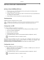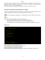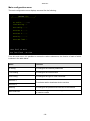
1
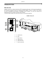
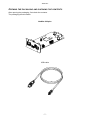
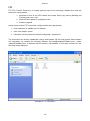
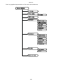
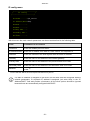
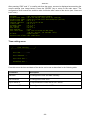
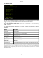
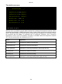
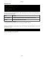
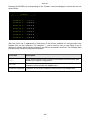
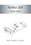
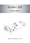
0MNACCSA3ENUC - ENGLISH - INTRODUCTION Thank you for choosing our product. The accessories described in this manual are of the highest quality, carefully designed and built in order to ensure excellent performance. This manual contains detailed instructions on how to install and use the product. It should be kept with care near the NetMan Plus, so that it can be consulted for information on how to use and make the most of your device. IT SHOULD BE READ BEFORE YOU START WORKING ON THE DEVICE. Symbols used in this manual: Warning Indicates important information that must not be ignored. Information Provides notes and useful suggestions for the User. SAFETY This part of the manual contains SAFETY precautions that must be followed scrupulously. The device has been designed for professional use and is therefore not suitable for use in the home. The device has been designed to operate only in closed environments. It should be installed in rooms where there are no inflammable liquids, gas or other harmful substances. Take care that no water or liquids and/or foreign bodies fall into the device. In the event of a fault and/or impaired operation of the device, do not attempt to repair it but contact the authorized service centre. The device must be used exclusively for the purpose for which it was designed. Any other use is to be considered improper and as such dangerous. The manufacturer declines all responsibility for damage caused by improper, wrong and unreasonable use. -2- - ENGLISH - ENVIRONMENTAL PROTECTION In the development of its products, the company devotes abundant resources to analysing the environmental aspects. All our products pursue the objectives defined in the environmental management system developed by the company in compliance with applicable standards. No hazardous materials such as CFCs, HCFCs or asbestos are used in this product. When evaluating packaging, the choice of material has been made favouring recyclable materials. Please separate the different material of which the packaging is made and dispose of all material in compliance with applicable standards in the country in which the product is used. DISPOSING OF THE PRODUCT The device contains electronic PCBs and batteries which are considered TOXIC. When the product reaches the end of its operating life, dispose of it in accordance with applicable local legislation. Disposing of the product correctly contributes to respecting the environment and personal health. © No part of this manual may be reproduced without the prior written permission of the manufacturer. The manufacturer reserves the right to modify the product described in this manual at any time and without notice. -3- - ENGLISH - CONTENTS PRESENTATION __________________________________________________ 6 DESCRIPTION __________________________________________________________ 6 OPENING THE PACKAGING AND CHECKING THE CONTENTS __________________________ 7 NETWORK PORT ________________________________________________________ 8 MICRO-USB COMMUNICATION PORT __________________________________________ 8 NETWORK SERVICES _____________________________________________________ 8 SSH _____________________________________________________________________ 8 Serial network ____________________________________________________________ 8 Wake-on-LAN_____________________________________________________________ 8 HTTP ____________________________________________________________________ 9 SNMP ___________________________________________________________________ 9 UDP_____________________________________________________________________ 9 Modbus _________________________________________________________________ 9 FTP ____________________________________________________________________ 10 Email___________________________________________________________________ 11 Reports_________________________________________________________________ 12 UPS VALUES AND EVENTS HISTORY LOG ARCHIVE _______________________________ 13 Eventlog ________________________________________________________________ 13 Datalog _________________________________________________________________ 14 ENVIRONMENTAL SENSORS (OPTIONAL)_______________________________________ 15 Available sensors ________________________________________________________ 15 INSTALLATION AND CONFIGURATION ______________________________ 16 INSTALLATION OF NETMAN 202 PLUS ________________________________________ 16 CONFIGURATION _______________________________________________________ 16 Configuration via USB ____________________________________________________ 16 Configuration via ssh _____________________________________________________ 16 Saving the configuration and applying the changes ____________________________ 17 Start menu ______________________________________________________________ 17 Main configuration menu __________________________________________________ 18 IP config menu __________________________________________________________ 21 Time setting menu _______________________________________________________ 22 -4- - ENGLISH - Scheduled NTP menu _____________________________________________________ 24 UPS config menu ________________________________________________________ 25 Services 1 menu _________________________________________________________ 26 SNMPv1 config menu _____________________________________________________ 27 SNMPv1 community menu _________________________________________________ 27 Email config menu _______________________________________________________ 28 Email logic menu_________________________________________________________ 29 Miscellaneous menu ______________________________________________________ 30 Activation 1 menu ________________________________________________________ 31 Services 2 menu _________________________________________________________ 31 Wake-On-LAN address menu_______________________________________________ 32 Wake-On-LAN delay menu _________________________________________________ 32 Activation 2 menu ________________________________________________________ 33 Sensors Config menu _____________________________________________________ 33 I/O Sensors menu ________________________________________________________ 35 Threshold sens menu _____________________________________________________ 36 Security menu ___________________________________________________________ 37 Save and load menu ______________________________________________________ 39 Expert mode ____________________________________________________________ 39 Configuration of several devices____________________________________________ 43 MONITORING WITH HTTP _________________________________________________ 43 View HTTP ______________________________________________________________ 44 Setup HTTP _____________________________________________________________ 45 MODBUS TCP/IP PROTOCOL ______________________________________________ 48 FIRMWARE UPDATE _____________________________________________________ 53 TECHNICAL DATA ________________________________________________ 54 SPECIFICATIONS FOR THE CABLING OF THE NETWORK CABLE _______________________ 54 TECHNICAL SPECIFICATIONS _______________________________________________ 54 -5- - ENGLISH - PRESENTATION DESCRIPTION NetMan 202 plus is a device that allows UPS management through a LAN (Local Area Network); the accessory supports all the main network protocols (SNMP v1 and v3, TCP/IP, HTTP and so on) and is compatible with Ethernet 10/100Mbps IPv4/6 networks. The UPS can therefore be integrated easily into medium and large-sized networks. The device also records UPS values and events in the history log archive. NetMan 202 plus A: network port; B: LED C: Reset button D: USB terminal E: USB (reserved) F: Serial (reserved) -6- - ENGLISH - OPENING THE PACKAGING AND CHECKING THE CONTENTS After opening the packaging, first check the contents. The packaging should contain: NetMan 202 plus USB cable -7- - ENGLISH - NETWORK PORT NetMan plus connects to 10/100 Mbps Ethernet networks by means of connector RJ45 (see paragraph “Specifications for the cabling of the network cable”). The LEDs built into the connector describe the status of the network: Left LED: 1. on and yellow if the 10/100Mbps mode link is present 2. on and green if the 10Mbps mode link is present Right LED: 1. on and yellow during transmission in full-duplex mode 2. on and green during transmission in half-duplex mode MICRO-USB COMMUNICATION PORT NetMan plus makes available an usb communication port through which it is possible to configure NetMan plus (see paragraph “Configuration via RS-232 serial line”) NETWORK SERVICES NetMan plus implements a series of services based on the main network protocols. These services can be activated or deactivated according to requirements (see paragraph “Configuration”). A brief description for each of these is given below. SSH By means of a ssh client (available on all the main operating systems) a remote connection with NetMan plus can be established to change its configuration (see paragraph “Configuration via ssh”). Serial network It’s possible to enable a network connection together with Serial network compatible software (for example UPSTools) for UPS event log download. Wake-on-LAN NetMan plus can send “Wake-on-LAN” command for remote computers boot. -8- - ENGLISH - HTTP Using the HTTP (Hyper Text Transfer Protocol), is possible to configure the NetMan plus and the status of the UPS can be monitored by means of a web browser without having to install additional software (see paragraph “Monitoring with HTTP”). All the most popular web browsers are supported. SNMP SNMP (Simple Network Management Protocol) is a communication protocol that allows a client (manager) to make requests to a server (agent). NetMan plus is an SNMP agent. To exchange information, manager and agent use an addressing technique called MIB (Management Information Base). There is an MIB file for each agent, defining which variables can be requested and the respective access rights. The agent can also send messages (TRAP) without a prior request from the manager, to inform the latter of particularly important events. SNMPv3 is the evolution of SNMP and introduces new important features related to security. (See paragraph “SNMPv3”). UDP UDP (User Datagram Protocol) is a low level network protocol that guarantees speed in the exchange of data and low network congestion. It is the protocol used by the UPSMon software for monitoring and control of the UPS. The UDP connection uses the UDP 33000 port by default but can be configured on other ports according to requirements. Modbus The UPS status can be monitored by means of the standard network protocol MODBUS TCP/IP. This service is always active on the TCP port 502. The supported function are listed on section “Modbus TCP/IP protocol”, together with the accessible registers. -9- - ENGLISH - FTP FTP (File Transfer Protocol) is a network protocol used for file exchange. NetMan plus uses this protocol for two purposes: 1. download of files of the UPS values and events history log archive (Datalog and Eventlog) with user “user” 2. download and upload of configuration files 3. firmware upgrade In both cases a client FTP is required, configured with these parameters: Host: hostname or NetMan plus IP address User: see chapter “Users” Password: current password (default configuration: “password”) The connection can also be established using a web browser (all the most popular web browsers are supported), by inserting the following address: ftp://user@<address.NetMan plus>, where <address.NetMan plus> is replaced with the device’s real address. In this case a screen like the following will be displayed. Example of FTP connection - 10 - - ENGLISH - Email NetMan plus can send a notification e-mail if one or more alarm conditions occur. The e-mails can be sent to up to three recipients and they can be sent for seven different kinds of alarm. SMTP (Simple Mail Transfer Protocol) is the protocol used to send the e-mails. They are sent to an SMTP server on port 25. For more details, see paragraph “Configuration” Example of notification e-mail - 11 - - ENGLISH - Reports NetMan plus can send periodic e-mails with an attachment containing the files of the UPS values and events history log archive. This service can be used to periodically save the history log archives. The “Email” service must be enabled in order to send reports; the reports are sent to all the addresses configured for this service (for more details see paragraph “Configuration”). Example of report e-mail - 12 - - ENGLISH - UPS VALUES AND EVENTS HISTORY LOG ARCHIVE NetMan plus records the UPS values (Datalog) and events (Eventlog) in a history log archive. The data are saved to file in text format and can be read either by means of an electronic spreadsheet (which allows the data to be ordered chronologically) or by any text editor. The format used to record the date and time is of the type: MM/DD/YY HH:MM:SS Eventlog The Eventlog service is always active and records all relevant UPS events in the ‘event.log’ file. The file can be downloaded via FTP or sent by e-mail using the “Email report” service. The data are saved in circular list mode, thus the most recent data are saved by overwriting the oldest data. Example of Eventlog - 13 - - ENGLISH - Datalog The Datalog service records the main UPS data in the ‘data.log’ file. The file can be downloaded via FTP or can be sent by e-mail using the “Email report” service. The following data are monitored: Input voltage line 1 Input voltage line 2 Input voltage line 3 Input frequency Output voltage line 1 Output voltage line 2 Output voltage line 3 Load on line 1 Load on line 2 Load on line 3 The interval of time between one recording and the next (Log frequency) can be configured by the user (see paragraph “Miscellaneous Menu”). The data are saved in circular list mode, thus the most recent data are saved by overwriting the oldest data. Data for up to 256 different points of time can be recorded. Example of Datalog - 14 - - ENGLISH - ENVIRONMENTAL SENSORS (OPTIONAL) Is possibile to connect to NetMan plus the environmental sensors for monitoring temperature, humidity and digital input/output. The information provided by these sensors can be showed with the UPS monitoring and control software or with a web browser (the HTTP service must be active). The values provided by the sensors may also be requested with SNMP according to the RFC 3433 standard. The MIB file is inside the bundled CD. Available sensors Temperature: detects the environmental temperature in °C. Humidity & Temperature: detects the relative humidity in % and the environmental temperature in °C. Digital I/O & Temperature: detects the environmental temperature in °C and features a digital input and a digital output. It is possible to connect up to 3 environmental sensor to a NetMan plus (for sensor installation please see the sensors’ manual). - 15 - - ENGLISH - INSTALLATION AND CONFIGURATION INSTALLATION OF NETMAN 202 PLUS 1. Remove the cover of the UPS expansion slot by removing the two retaining screws. 2. Insert NetMan 202 plus in the slot. 3. Connect the device to the network by means of connector RJ-45 (see “Specifications for the cabling of the network cable”) 4. Secure Netman in the slot using the two screws removed previously. CONFIGURATION NetMan plus can be configured via usb or via ssh. NetMan plus needs approx. 30 seconds to become operational from when it is powered up; before this time the device may not respond to commands that are sent to it Configuration via USB To configure NetMan plus via USB, it is necessary to: Connect, with the USB cable provided, the micro-USB port with the USB port of the PC execute the software HyperNetman press the “Enter” key of the PC at the login prompt, enter “admin” at the password prompt, enter the current password (default configuration: “admin”) During password’s typing, no character is shown. Once login has been effected, the screen of the start menu is displayed. From this screen it is possible to access the various menus to change NetMan plus settings (see paragraph “Main configuration menu” and following paragraphs). Note: at the first login it is necessary to access with user admin (see chapter “Users”). Configuration via ssh To configure NetMan plus via ssh it is necessary to: execute a ssh client on a PC connected in a network to NetMan plus set with the IP address of the device to be configured at the login prompt, enter “admin” at the password prompt, enter the current password (default configuration: “admin”) During password’s typing, no character is shown. - 16 - - ENGLISH - Once login has been effected, the screen of the start menu is displayed. From this screen it is possible to access the various menus to change NetMan plus settings (see paragraph “Main configuration menu” and following paragraphs). Note: at the first login it is necessary to access with user admin (see chapter “Users”). Saving the configuration and applying the changes In order to make the new configuration effective, it is necessary to save it in the flash memory; this action automatically reboot the device (see paragraph “Menu Save and load”). The clock settings (see paragraph “Time settings Menu”) become effective without saving. Users It is possible to access to NetMan 202 plus with various users: admin (password admin): user with right to modify the configuration fwupgrade (password fwupgrade): user with right to upgrade the firmware user (password user): user with right to read but not modify the configuration and the log Start menu /------------------------/ / Netman 202 plus / /------------------------/ Setup..........:<-View status....: Change password: Service log....: Expert mode....: Press [ESC] for logout SysVer. 0.0 - AppVer. 00.00 Select Setup to enter main configuration menu. Select View status to see the status of the device (UPS). Select Change password to modify the password. Select Service log when requested by the service. Select Expert mode for entering Expert mode (more information at paragraph “Expert mode”) - 17 - - ENGLISH - Main configuration menu The main configuration menu displays a screen like the following: /------------------------/ / NetMan plus / /------------------------/ IP config......:<-Time setting...: UPS config.....: Services 1.....: Services 2.....: Security.......: Save and load..: Press [Esc] to quit Data from flash - On Line From this main menu it is possible to access the various submenus, the function of each of which is shown in the table below. Menu Function IP config To configure the network parameters Time setting To configure the internal clock UPS config To configure the type of UPS connected Services 1 To activate and/or deactivate device services Services 2 Security To configure the password and access to the network Save and load To save a configuration thus making it effective in the event of a device restart - 18 - - ENGLISH - To move within this menu and the following menus, use the keys as described in the following table; the arrow or the cursor shows the current selection. Key Function Direction keys (Arrow up, down, right, left) To move the cursor within the menus Tab Goes on to next option Choice of submenu Enter (1) Confirmation of characters entered Exit main menu (2) Esc (1) Return to previous menu (1) (2) Some keys can have a different function depending on the menu. To exit from a menu a confirmation (‘Y’ or ‘N’) is required after pressing the ESC key. The screen also displays some messages describing the kind of configuration data displayed and the status of the UPS. The meaning of these messages is described below. Data from flash: means that the configuration has been loaded from the flash memory Default data: means that the configuration has been reset to the default values - 19 - - ENGLISH - Here is a graphical rapresentation of the menus and submenus: - 20 - - ENGLISH - IP config menu /------------------------/ / IP config / /------------------------/ Hostname.......:ups_server IP address/DHCP:dhcp Netmask........: Gateway........: Primary DNS....: Secondary DNS..: Mailhost.......: With this menu the main network parameters can be set as described in the following table. Field Parameters to be inserted Hostname Enter the NetMan plus host name IP address/DHCP Enter the IP address for a static IP; enter “DHCP” for a dynamic IP Netmask Enter the netmask to be used together with the static IP address Gateway Enter the name or the address of the network gateway Primary DNS Enter the name or the address of the preferred DNS to be used Secondary DNS Enter the name or the address of the alternative DNS to be used Mailhost Enter the name or the address of the SMTP server to be used to send emails. (1) (1) Ensure that the SMTP server accepts connections on port 25. If a static IP address is assigned to the device, all the fields must be configured with the network parameters. If a dynamic IP address is assigned, just enter ‘dhcp’ in the “IP Address/DHCP” field and provide a hostname; all the other options should be ignored because these are automatically configured with DHCP - 21 - - ENGLISH - After pressing “ESC” and “Y” to confirm exit from the menu, a screen is displayed summarizing the current settings (see image below). Press the “ENTER” key to return to the main menu. The configuration must however be saved to make it effective after restart of the device (see “Save and load” menu). Hostname : Current IPv4 addr.: Current IPv6 addr.: Default IPv4 GW : Ethernet Address : Primary DNS : Secondary DNS : DNS Timeout : DHCP Server : DHCP Enabled : DHCP Lease Ends : ups_server.mynetwork.domain 10.1.10.187/16 (255.255.0.0) (active) fe80:0:0:0:260:35ff:fe02:4184/64 (active) 10.1.4.1 00:60:35:02:41:84 10.1.4.2 10.3.4.1 0 (ms) 10.1.5.1 true Sun Jun 05 00:00:12 GMT 2005 (66 hr, 40 min, 38 seconds left) Mailhost : mymailserver Restore From Flash: Not Committed Time setting menu /------------------------/ / Time setting / /------------------------/ Set time.......:<-Set timezone...: Sync with NTP..: Scheduled NTP..: From this menu the time and date of the device can be set as described in the following table. Command Description Set time To configure the time and date manually Set timezone To configure the time zone Sync with NTP To synchronize the clock with an NTP server Scheduled NTP To configure the scheduled NTP - 22 - - ENGLISH - Pressing the “ENTER” key corresponding to the “Set time” command displays a screen like the one shown below. Current date is Wed Jun 15 08:09:40 GMT 2005 Insert new date and clock time in this form: MMDDYYYYHHMMSS 06152005081000 Current date is Wed Jun 15 08:10:00 GMT 2005 Enter the date and time in the format shown, then press the ENTER key and then “ESC” to exit. Pressing the “ENTER” key corresponding to the “Set timezone” command displays a screen where is possible to modify the timezone. Examples of available timezones: Europe/Rome CET GMT Asia/Singapore Etc/GMT+4 SystemV/HST10 Enter the time zone selected from those shown, then press the ENTER key and then “ESC” to exit. Pressing the “ENTER” key corresponding to the “Sync with NTP” command displays a screen like the one shown below. Current date is Thu Jun 16 14:17:06 ECT 2005 Insert IP Address or host name of the NTP server to synchronize time: leg Synchronizing time to server: server.mycompany New system time: 16 Jun 2005 12:17:00 GMT Current date is Thu Jun 16 14:17:01 ECT 2005 Enter the name or the address of the NTP server with which the device is to be synchronized. In this case the time has to be within the GMT time zone, thus it may be necessary to correct the current time zone with the “Set timezone” command. - 23 - - ENGLISH - Scheduled NTP menu /------------------------/ / Scheduled NTP / /------------------------/ NTP server.....:time_server Sync only at...:13 hour (0 - 23) Sync only at...:* day of week (0 - 6) (Sunday=0 or 7) OR sun,mon,tue ... Sync only at...:1 day of month (1 - 31) Insert * where the value is not needed. With this menu is possible to schedule the NTP synchronization. Is possible to specify the time and frequency for performing a synchronization. For each field is possible to enter the precise condition or leaving ‘*’ which means always. On the example above, synchronization will be performed every 1st day of month at 13:00, regardless of the day of week. Field Parameters to be inserted NTP server Enter the name or address of the NTP server Sync only at (h) Enter the hour when the synchronization should occur, or ‘*’ Sync only at (w) Enter the day of week when the synchronization should occur, or ‘*’ Sync only at (m) Enter the day of month when the synchronization should occur, or ‘*’ - 24 - - ENGLISH - UPS config menu /------------------------/ / UPS config / /------------------------/ PRTK Code......:GPSER11201XX Name...........:ups3 UPS Address....:1 Serial number..:324321 With this menu the UPS parameters must be set as described in the following table, for the UPS to be able to communicate correctly with the device. Field Parameters to be inserted PRTK Code Enter the PRTK code indicated at the back of the UPS(1) Name Enter the identifying name of the UPS UPS Address Insert 1 Serial number Enter the UPS identification code (1) The PRTK code is formed of 12 alphanumeric characters. - 25 - - ENGLISH - Services 1 menu /------------------------/ / Services 1 / /------------------------/ SNMP config....:<-SNMP community.: Email config...: Email logic....: Miscellaneous..: Activation 1...: With this menu the configuration screens of the various services can be accessed as described in the following table. Menu Function SNMP config To configure the SNMP service SNMP community Email config To configure the e-mail service Email logic Miscellaneous To configure the other options Activation 1 To configure the services to be activated As well as being configured, the services must also be activated to function correctly (see paragraph “Activation menu”). It is recommended to activate only the services used. - 26 - - ENGLISH - SNMPv1 config menu /------------------------/ / SNMPV1 config / /------------------------/ Trap receiver 1:powernetguard Trap receiver 2:192.168.5.96 Trap receiver 3: Trap receiver 4: Trap receiver 5: Trap receiver 6: Trap receiver 7: With this menu the IP addresses to which traps are sent can be configured. Traps are SNMP messages that are sent to an SNMP manager for alarm notification. Traps can be sent to seven different hosts. SNMPv1 community menu /------------------------/ / SNMPV1 community / /------------------------/ Get community..:public Set community..:private Trap community.:public With this menu the protection password of the SNMP messages (SNMP Communities) can be configured as described in the following table. Field Parameters to be inserted Get community Enter the community for read access Set community Enter the community for write access Trap community Enter the community for traps - 27 - - ENGLISH - Email config menu /------------------------/ / Email config / /------------------------/ Email address 1:[email protected] Email address 2:[email protected] Email address 3:[email protected] Sender address.:NetMan_plus Customer.......:MyCustomer Report interval:01-05:10 DD-HH:MM User name......:User 1 Password.......:Password This menu may be used to configure the addresses to which to send the alarm notification and report e-mails and other parameters of the e-mail service as described in the following table. Field Parameters to be inserted Email address 1 Email address 2 Email address 3 Sender address Customer Report interval User name Password (1) Enter the e-mail addresses to which to send the alarm notifications and reports (see note). Enter the address from which the e-mails are sent. (1) Enter an identifying string; this additional information is included in the email. Enter the delay, measured in days, between the sending of one report email and the next by using exactly 2 figures, followed by a line, an finally by the hour and minutes on which the email should be sent. If the server requires authentication, insert the “User name”. If the server requires authentication, insert the password. do not use the “space” character in this field After inserting the data and pressing the “ESC” key to exit from the menu, the service can be tested by pressing the “T” key. If the test is performed, a “@” is displayed and a test email is sent to all the configured email addresses. After this the previous menu is shown. Report e-mails are sent to all the addresses inserted; for alarm notification e-mails see paragraph “Email logic menu”. - 28 - - ENGLISH - Email logic menu /------------------------/ / Email logic / /------------------------/ Email 1 Email 2 Email 3 Logic: UPS Lock.......: X<-- 0 0 And Ovrload/Ovrtemp: X 0 0 And UPS Failure....: X 0 0 And On bypass......: X 0 0 And Battery work...: X 0 0 And Battery low....: X 0 0 And Communic lost..: X 0 0 And With this menu it can be established to which addresses the e-mails will be sent when certain events occurs. One or more addresses can be associated with each event and in the latter case, when the event occurs, notification e-mails will be sent to all the addresses associated with it. Use the ENTER key to change the selected configuration (“X” or “0”). X: when the event occurs, NetMan plus sends a notification e-mail to the corresponding addresses (see “Email logic menu” to set the addresses); 0: when the event occurs, NetMan plus does not send a notification e-mail to the corresponding addresses; The following table describes the meaning of the events. These can vary depending on the UPS connected. Event Meaning UPS Lock UPS is locked Ovrload/Ovrtemp UPS in overload or in overtemperature UPS Failure Failure of the UPS On bypass Operation from bypass Battery work Operation from battery Battery low Battery low Communic lost Communication between the UPS and the device has been interrupted SENTR level 2 SENTR level 3 Presence of an internal UPS failure (this condition emulates the level of modem alarm for UPSs of the SENTR type) Presence of a failure in the UPS, excluding those envisaged in the previous point (this condition emulates the level of modem alarm for UPSs of the SENTR type) - 29 - - ENGLISH - Miscellaneous menu /------------------------/ / Miscellaneous / /------------------------/ Log frequency..:5 sec UDP Port.......:33000 sysContact.....:Administrator sysName........:My Server sysLocation....:new building With this menu further device parameters can be configured as described in the following table. Field Parameters to be inserted Log frequency Enter the delay, measured in seconds, between one data log and the next (see paragraph “Datalog”) UDP Port Enter the port where the UDP service is started (1) sysContact sysName Enter the string to be associated with these SNMP variables sysLocation (1) This port must be the same as configured in the UPSMon software - 30 - - ENGLISH - Activation 1 menu /------------------------/ / Activation 1 / /------------------------/ Enable telnet..:[ON/off]<-- Enable FTP.....:[ON/off] Enable HTTP....:[ON/off] Enable DataLog.:[ON/off] Enable Modem Tx:[on/OFF] Enable Modem Rx:[on/OFF] Enable SNMP....:[ON/off] Enable Email...:[ON/off] Enable UDP.....:[ON/off] Enable Report..:[ON/off] With this menu the services implemented in NetMan plus can be activated or deactivated: Use the ENTER key to change the selected configuration (“ON” or “OFF”). ON (green characters): service active OFF (red characters): service not active It is recommended to activate only the services used. Services 2 menu /------------------------/ / Services 2 / /------------------------/ WakeOnLan addr.:<-WakeOnLan delay: Activation.2...: Sensors config : I/O Sensors....: Threshold sens.: With this menu the configuration screens of the various services can be accessed as described in the following table. Menù Funzione WakeOnLan addr. WakeOnLan delay Activation 2 To configure the Wake-on-LAN service To configure the services to be activated Sensors. config I/O Sensors To configure the environmental sensors Threshold sens As well as being configured, the services must also be activated to function correctly (see paragraph “Activation 2 menu”). It is recommended to activate only the services used. - 31 - - ENGLISH - Wake-On-LAN address menu /------------------------/ / Wake-on-LAN address / /------------------------/ MAC Address 1..:00-12-3F-2B-F6-6F MAC Address 2..:aa-bb-cc-dd-ee-ff MAC Address 3..:00-00-00-00-00-00 MAC Address 4..: MAC Address 5..: MAC Address 6..: MAC Address 7..: MAC Address 8..: With this menu is possible to insert up to 8 MAC address to execute Wake-on-LAN. Please make sure that your PC supports this function, and that it is correctly configured. Wake-On-LAN delay menu /------------------------/ / Wake-on-LAN delay / /------------------------/ Address 1 delay:2 sec. Address 2 delay:40 sec. Address 3 delay:2 sec. Address 4 delay: sec. Address 5 delay: sec. Address 6 delay: sec. Address 7 delay: sec. Address 8 delay: sec. With this menu is possible to insert the delay times for each Wake-on-LAN. - 32 - - ENGLISH - Activation 2 menu /------------------------/ / Activation 2 / /------------------------/ Enable Serial N:[ON/off]<-Enable Sensors.:[ON/off] Enable WOL :[on/OFF] With this menu the services implemented in NetMan plus can be activated or deactivated: Use the ENTER key to change the selected configuration (“ON” or “OFF”). ON (green characters): service active OFF (red characters): service not active It is recommended to activate only the services used. Sensors Config menu To enter on the “Sensors config” menu is necessary to enable the “Sensors” service (Activation 2 menu) and to save the configuration (Save and load menu). Sensors Devices Press [C] to change sensors, [E] to exit Enter on the “Config sensor” menu, connect the first sensor and press “C”. After some instants the device will be recognized and the device will be given an identifier number [1]. Connect the next sensor, if present, and press “N”. After some instants the device will be recognized and the device will be given an identifier number [2]. Repeat the procedure for all the sensors and when the configuration is finalized press “Y”. Sensors Devices [1] Sensor Digital I/O + Temperature (140000009A204C28) + Digital I/O (220000003B8C9F12) + 1 Input + 1 Output [2] Sensor Digital I/O + Temperature (510000009A154228) + Digital I/O (BB0000003BA2FF12) + 1 Input + 1 Output [3] Sensor Temperature (F100000013BE0628) + Temperature [4] Sensor Temperature (6C0000009F6D6128) + Temperature [5] Sensor Humidity (4D00000083FF3326) + Humidity + Temperature Press [Y] to confirm, [N] to insert a new sensor For proper working of the devices, it is necessary to add just one device for each iteration and wait that it is recognized by NetMan plus. - 33 - - ENGLISH - Example: how to connect a Temperature sensor, a Humidity & Temperature sensor and a Digital I/O & Temperature sensor in exactly this order. Sensors Devices Press [C] to change sensors, [E] to exit Connect the first sensor (Temperature), and press “Y”. Sensors Devices [1] Sensor Temperature (F100000013BE0628) + Temperature Press [Y] to confirm, [N] to insert a new sensor Wait until the first sensor is identified and then connect the second sensor (Humidity & Temperature), and press “N”. Sensors Devices [1] Sensor Temperature (F100000013BE0628) + Temperature [2] Sensor Humidity (4D00000083FF3326) + Humidity + Temperature Press [Y] to confirm, [N] to insert a new sensor Wait until the second sensor is identified and then connect the third sensor (Digital I/O & Temperature), and press “N”. Sensors Devices [1] Sensor Temperature (F100000013BE0628) + Temperature [2] Sensor Humidity (4D00000083FF3326) + Humidity + Temperature [3] Sensor Digital I/O + Temperature (510000009A154228) + Digital I/O (BB0000003BA2FF12) + 1 Input + 1 Output Press [Y] to confirm, [N] to insert a new sensor Press “Y” to confirm. - 34 - - ENGLISH - I/O Sensors menu /------------------------/ / Output / /------------------------/ UPS Lock.......: -<-- Ovrload/Ovrtemp: - UPS Failure....: - On bypass......: 4 Battery work...: 3 Battery low....: - Communic lost..: - Input sensor...: 1 Press [Esc] to quit With this menu is possibile to associate a digital output of the installed sensors to one or more events of the UPS. The output will be closed when the associated event happens. Press ENTER to select the output. The identification number is the same which is associated to the sensor during installation. The following table describes the meaning of the events. These can vary depending on the UPS connected. Event Description UPS Lock UPS is locked Ovrload/Ovrtemp UPS in overload or in overtemperature UPS Failure Failure of the UPS On bypass Operation from bypass Battery work Operation from battery Battery low Battery low Communic lost Communication between the UPS and the device has been interrupted The “Input sensor” event allows to associate a digital output with the digital input of the Digital I/O & Temperature sensor which is installed with the lowest identification number (the first that was detected during configuration). The state of the input (open/closed) is reported to the output of the selected sensor. - 35 - - ENGLISH - Threshold sens menu /------------------------/ / Threshold sens / /------------------------/ Temperature max:100 degree C Temperature min:20 degree C Temp hysteresis:5 degree C Humidity Max...:100 % RH Humidity Min...:0 % RH Hum hysteresis.:5 % RH Press [Esc] to quit With this menu is possible to set the alarm threshold for humidity and temperature sensors. When exceeding the threshold, a SNMP alarm trap is sent. A trap is sent every minute until the alarm is active. The alarm ceases to be active when the outbound value (temperature or humidity) is under the threshold with the degree of hysteresis that is configured. (Example: with a maximum temperature of 30°C and 3°C hysteresis, the alarm is activated when the temperature reaches 30°C and is removed when the temperature at 27°C). Menu Significato Temperature max Threshold for maximum temperature Temperature min Threshold for minimum temperature Temp hysteresis Hysteresis for removing temperature alarm (high and low) Humidity max Threshold for maximum humidity Humidity min Threshold for minimum humidity Hum hysteresis Hysteresis for removing humidity alarm (high and low) - 36 - - ENGLISH - Security menu /------------------------/ / Security / /------------------------/ UDP Password...:<-Firewall.......: From this menu the setup password, the UDP password and the firewall can be configured as described in the following table. Menu Function UDP Password To change the password used for UDP/UPSMon communication (2) Firewall To configure access from the network (1) (2) default configuration: “password” this password must be the same as the one used by the UPSMon software Pressing the ENTER key corresponding to the “UDP Password” command displays a screen like the one shown below. Enter the new UDP password: Confirm the new UDP password: Enter, as requested, the new password. - 37 - - ENGLISH - Pressing the ENTER key corresponding to the “Firewall” command displays a screen like the one shown below. /------------------------/ / Firewall / /------------------------/ Access IP 1....:*.*.*.* Access IP 2....:0.0.0.0 Access IP 3....:0.0.0.0 Access IP 4....:0.0.0.0 Access IP 5....:0.0.0.0 Access IP 6....:0.0.0.0 Access IP 7....:0.0.0.0 With this menu the IP addresses or hostnames of the devices enabled for communication with NetMan plus can be configured. The character “*” can be used for one or more fields of the IP address to indicate that all values between 0 and 255 are accepted in that field. The following table provides some possible configuration examples. IP Access Description *.*.*.* All the devices present on the network are enabled to communicate with NetMan plus (default configuration) 10.1.10.* The devices with addresses between 10.1.10.0 and 10.1.10.255 are enabled to communicate with NetMan plus myserver.mydomain Hostname of the device enabled to communicate with NetMan plus - 38 - - ENGLISH - Save and load menu /------------------------/ / Save and load / /------------------------/ Apply changes..:<-Revert changes.: Reset default..: With this menu the configuration can be saved to make it effective or to load other configurations as described in the following table. Function Description Apply changes Saves the configuration in flash memory and then automatically restarts to make the changes effective Revert changes Cancels the changes and reloads the last saved configuration (excluding the the clock -Time setting- configurations) Reset default Loads the default configuration (1) see paragraph “Configuration of several devices” Expert mode Expert mode enables the configuration of advanced parameters that should be set by skilled technicians. These commands are supported: help prints the help get shows all values set <VAR> <VALUE> set VAR to VALUE reboot reboot the NetMan exit closes the connection - 39 - - ENGLISH - SNMPV3 CONFIGURATION For configuring SNMPv3 access, is necessary to edit snmp.conf. This file can be downloaded and uploaded with FTP with user “admin” (default password is “admin”). If this file is not present, SNMPv1 will be used. Each line of the file is parsed by netman 202 plus and must begin with one of these keyword: #: for comment, the line is skipped. addUser: for adding a new user and setting the passwords addGroup: for putting a user into a group addAccessEntry: for enabling access privileges to a group addView: for adding privileges addManager: for adding SNMP Manager which will receive SNMP traps. The correct syntax for addUser is: addUser <userName> <authProtocol> <privProtocol> <authPassword> <privPassword> <userName> is the name of the user. <authProtocol> is the protocol for authentication of this user during SNMP sessions. Possible values are: noauth (no authentication will be used) md5 (MD5 will be used for authentication) sha (SHA will be used for authentication) <privProtocol> is the protocol for privacy of this user during SNMP sessions. Possible values are: nopriv (no privacy will be used) des (DES will be used for privacy) <authPassword> is the password for authentication. It must be set to * when not used. <privPassword> is the password for privacy. It must be set to * when not used. The correct syntax for addGroup is: addGroup <securityModel> <userName> <groupName> <securityModel> is the security model. When using authentication and/or privacy, securityModel must be USM. Possible values are: USM (User-based Security Model with SNMPv3) v2 (SNMPv2) v1 (SNMPv1) <userName> is the name of the user, must match one of the user name defined with addUser. <groupName> is the name of the group. Please note that a userName can be assigned to only one group. The correct syntax for addAccessEntry is: addAccessEntry <groupName> <contextName> <securityModel> <securityType> <contextMatch> <readView> <writeView> <notifyView> <groupName> is the name of the group to which this access right applies, must match one of the group name defined with addGroup. <contextName> is the name of the context. <securityModel> is the security model that must be used in order to gain access to this access right, must match the security model defined with addGroup. - 40 - - ENGLISH - <securityType> is the minimum security level that must be used to gain access to this access right. Possible values are: noauthnopriv (no authentication and no privacy) authnopriv (authentication but no privacy) authpriv (authentication and privacy) <contextMatch> the type of match required. Possible values are: exact (the context name must exactly match the value in contextName) prefix (the context name must match the first few starting characters of the value in contextName) <readView> the authorized MIB view name used for read access, must match one of the view name. <writeView> the authorized MIB view name used for write access, must match one of the view name. <notifyView> the authorized MIB view name used for notify access, must match one of the view name. The correct syntax for addView is: addView <viewName> <subtree> <mask> <included> <viewName> is the name of the view. <subtree> is the OID subtree which when combined with the corresponding instance of MASK defines a family of view subtrees. <mask> the mask for filtering OID. <included> the OID can be included or excluded. Possible values are: included (for including) excluded (for excluding) The correct syntax for addManager is: addManager <security> <ipAddress> <credentials> <securityType> <security> is the security type for the notification. Possible values are: USM (User-based Security Model with SNMPv3) V2 (SNMPv2) v1 (SNMPv1) <ipAddress> is the IP address of the SNMP manager. <credentials> is either the user name (when using USM security) or the trap community (when using v1 security) <securityType> is either: noauthnopriv (for SNMPv1 and SNMPv2) authpriv (for SNMPv3) addManager do not allow duplicate entries (one ipAddress can receive only one trap). - 41 - - ENGLISH - A sample snmp.conf is provided; the default users authorized are: Name Auth protoc ol Priv protoc ol Auth passwo rd Priv passwo rd unsecureUs er Noauth MD5 SHA MD5DES SHADES md5 Sha md5 Sha nopriv nopriv nopriv des des MD5UserAuthPassw ord SHAUserAuthPassw ord MD5DESUserAuthPassw ord SHADESUserAuthPassw ord MD5DESUserPrivPassw ord SHADESUserPrivPassw ord The SNMP agent will send SNMPv3 trap to address 10.2.10.1. - 42 - - ENGLISH - Configuration of several devices If several devices requiring similar configuration parameters are to be installed, configure the first card, connect via FTP with the admin user, download the configuration file, and upload them on all devices to be configured via FTP. Example of FTP connection for multiple installations MONITORING WITH HTTP The HTTP service uses TLS (transport layer security) in order to provide cryptographic security. However, the certificate used is self-signed and therefore the web browser may prompt a security alert. Once the hostname or the NetMan plus IP address has been inserted in your web browser, the following screen will be shown. From here is possible to view the status of the UPS and configure the NetMan plus. - 43 - - ENGLISH - View HTTP It is possible to view the status of the UPS without entering the login by pressing “View”. By pressing “View”, a screen like the one shown below will be displayed, with the main UPS operating data. - 44 - - ENGLISH - Besides the “Main” view, is possible to switch the view from the “Status” menu which includes also the “Nominal” view and the “Sensor” view (for viewing external sensors). It is also possible to download the event.log and data.log (if available) from the “Log” menu. Setup HTTP For configuration it will be requested to enter the log in and password. These are the same of ssh config and are required to modify the configuration. When inserting a valid log in and password is possible to configure the netman. - 45 - - ENGLISH - The settings are the same of ssh config. The user is logged out after 3 minutes of inactivity, or when the “Logout” is selected. By pressing submit the data for the current view is sent to the netman; by pressing reset the data for the current view is discarded. With HTTP each view is configured separately, therefore is required to press submit for each (for example, when changing device config and ip config is required to press submit on device config and on ip config). The changes becomes effective on next reboot. - 46 - - ENGLISH - Example of display via HTTP The following buttons are found on the left-hand side of the page: Nominal Data: opens a page displaying the nominal values of the UPS, the list of active alarms and a diagram of UPS operation (see image on next page) FTP: opens an FTP session (see paragraph ”FTP”) About: opens a page with copyright information - 47 - - ENGLISH - MODBUS TCP/IP PROTOCOL This service is always active on the TCP port 502. The supported function are listed below, together with the accessible registers. SUPPORTED FUNCTION SUPPORTED FUNCTION 1 2 3 4 6 16 (0x01) (0x02) (0x03) (0x04) (0x06) (0x10) FUNCTION DESCRIPTION BIT READING REGISTERS READING SINGLE REGISTER WRITING MULTIPLE REGISTER WRITING - 48 - ACCESSIBLE DATA AREA STATES STATES ALL ALL COMMANDS COMMANDS - ENGLISH - UPS: TABLES OF STATES, MEASUREMENTS, NOMINAL DATA AND COMMANDS REGISTER (1) BIT (2) UPS - STATES NUMBER ADDRESS Test in progress[0=No / 1=YES] Shutdown active [0=No / 1= YES] 1 0 Battery charged[0=No / 1= YES] Battery charging[0=No / 1= YES] Bypass bad[0=No / 1= YES] Normal operation[0=No / 1= YES] On bypass[0=No / 1= YES] Battery low[0=No / 1= YES] Battery working[0=No / 1= YES] UPS locked[0=No / 1= YES] Output powered[0=No / 1= YES] (1) (2) 2 1 3 2 4 3 58 47 Input Mains present[0=No / 1= YES] Alarm temperature[0=No / 1= YES] Alarm overload[0=No / 1= YES] UPS failure[0=No / 1= YES] Communication lost with UPS[0=No / 1= YES] NUMBER ADDRESS 1 2 3 4 5 6 7 8 9 10 11 12 13 14 15 16 1728 29 30 31 32 3348 4963 64 65128 0 1 2 3 4 5 6 7 8 9 10 11 12 13 14 15 1627 28 29 30 31 3247 4862 63 64127 The register number n must be addressed n-1 in the data packet The bit number n must be addressed n-1 in the data packet. REGISTER (1) UPS - MEASUREMENTS NUMBER ADDRESS 911 12 13 14 15 16 17 18 1921 22 23 24 25 26 27 28 2931 32 810 11 12 13 14 15 16 17 1820 21 22 23 24 25 26 27 2830 31 UNIT Input mains star voltage V1 Input mains star voltage V2 Input mains star voltage V3 Input current phase L1 Input current phase L2 Input current phase L3 Input frequency V V V 0.1*A 0.1*A 0.1*A 0.1*Hz Bypass mains star voltage V1 Bypass mains star voltage V2 Bypass mains star voltage V3 Bypass frequency Output star voltage V1 Output star voltage V2 Output star voltage V3 V V V 0.1*Hz V V V Output current phase L1 0.1*A - 49 - - ENGLISH - 33 34 35 36 37 38 39 40 41 42 43 44 4547 48 49 50 51 52 53 54 5558 59 60 61 62 63 64 6572 (1) 32 33 34 35 36 37 38 39 40 41 42 43 4446 47 48 49 50 51 52 53 5457 58 59 60 61 62 63 6471 Output current phase L2 Output current phase L3 Output peak current phase L1 Output peak current phase L2 Output peak current phase L3 Load phase L1 Load phase L2 Load phase L3 Output active power phase L1 Output active power phase L2 Output active power phase L3 Output frequency 0.1*A 0.1*A 0.1*A 0.1*A 0.1*A % % % 0.1 kW 0.1 kW 0.1 kW 0.1*Hz Battery voltage Positive battery voltage Negative battery voltage Battery current Remaining Battery Capacity 0.1*V 0.1*V 0.1*V 0.1*A % Remaining back-up time Total output energy (32 bit) Internal UPS temperature Sensor 1 temperature Sensor 2 temperature Minutes Least Significant Register Most Significant Register 0.1 kWh °C °C °C The register number n must be addressed n-1 in the data packet. Some measures may not be available for all the UPS. In this case, the relative register remains at 0xFFFF value. - 50 - - ENGLISH - REGISTER (1) UPS – NOMINAL DATA NUMBER ADDRESS 7377 78 79 80 8183 84 85 86 87112 7276 77 78 79 8082 83 84 85 86111 REGISTER Output nominal voltage (star) Output nominal frequency Output nominal power V 0.1*Hz 100*VA Battery nominal capacity (battery expansion included) Battery benches Battery type Ah (1 or 2) Integer (1) UPS - COMMANDS NUMBER ADDRESS 113 114 115 116 117 118 112 113 114 115 116 117 REGISTER (2) Command code Shutdown delay time Restore delay time Command result (2) (3) UNIT Integer Seconds Minutes (3) Integer (1) DIAGNOSTIC (1) UNIT NUMBER ADDRESS 119 120 118 119 Counter of processed correct messages Counter of processed NOT correct messages The register number n must be addressed n-1 in the data packet. Refer to “Command codes” paragraph Command result = Command code if command is handled from the UPS Command result = Command code + 100 if command is NOT handled from the UPS Command result = 0 if Command code is wrong - 51 - UNIT Integer Integer - ENGLISH - REGISTER (1) SPECIAL FLAGS (SENTR UPS) NUMBER ADDRESS 121 122 123 124 125 126 127 128 120 121 122 123 124 125 126 127 REGISTER Byte 1 of “s = xx..” code / Byte 2 of “s = ..xx” code Byte 1 of “c = xx..” code / Byte 2 of “c = ..xx” code Byte 1 of “b = xx..” code / Byte 2 of “b = ..xx” code Byte 1 of “r = xx..-..” code / Byte 2 of “r = ..xx-..” code Byte 3 of “r = ....-xx” code / Byte 1 of “i = xx..-..” code Byte 2 of “i = ..xx-..” code / Byte 3 of “i = ....-xx” code Byte 1 of “a = xx..-....” code / Byte 2 of “a = ..xx-....” code Byte 3 of “a = ....-xx..” code / Byte 4 of “a = ....-..xx” code (2) NUMBER ADDRESS 129 130÷131 128 129÷130 Firmware version Flag Flag Flag Flag Flag Flag Flag Flag In order to decode these registers, please refer to the UPS manual. UPS: COMMANDS CODES CODE (0x0001) (0x0002) (0x0003) (0x000C) (0x0014) (0x0016) UNIT Integer The register number n must be addressed n-1 in the data packet. 1 2 3 12 20 22 UNIT (1) NETMAN DATA (1) (2) COMMAND Command Shutdown Command Shutdown and Restore Delete Command (code 1, 2, 12) UPS on Bypass Test Battery Test Panel - 52 - - ENGLISH - FIRMWARE UPDATE The NetMan 202 plus firmware can be updated via FTP. Connect via FTP with the user “fwupgrade” (password “fwupgrade”) and copy the updated firmware. Then restart the card, by pressing the reset button or via SSH enter into the menu with user "admin" and select "Save changes". - 53 - - ENGLISH - TECHNICAL DATA SPECIFICATIONS FOR THE CABLING OF THE NETWORK CABLE To connect the device to the Ethernet (10Base-T) or Fast Ethernet (100Base-T) network, a UTP (Unshielded Twisted Pair) or STP (Shielded Twisted Pair) cable with RJ45 connectors is required. The cable must conform to the standard IEEE 802.3u 100Base-T with 2 pairs of UTP cables of category 5 or higher. The cable between the adaptor and the hub must not be more than 100m and not less than 2.5m. NETWORK CABLE CONNECTIONS Signal Pin # to Pin # TX+ 11 TX- 22 RX+ 33 RX- 66 Pins 1 and 2 must be connected to one twisted pair, pins 3 and 6 to another. TECHNICAL SPECIFICATIONS NetMan 202 plus Input voltage [Vdc] 12 Maximum input current [mA] 200 Operating temperature [°C] 0 ÷ +40 Storage temperature [°C] -5 ÷ +50 Operating relative humidity [%] 80 (max) Storage relative humidity [%] 90 (max) POWER SUPPLY ENVIRONMENTAL CONDITIONS - 54 - 0MNACCSA3ENUC