1
CX2033/CX2033Plus
MC560/MC560Plus
Maintenance Manual
07710C
Oki Data CONFIDENTIAL
Please refer to the
"Illustrated Parts Manual"
for spare part information.
Oki Data CONFIDENTIAL
Preface
This maintenance manual describes maintenance methods in filed of MC560/CX2033MFP/ES5460MFP targeting service personnel.
Names of components that require procurement, such as printed circuit board, are assigned with
numbers.
(Example) ABCD-3 Printed circuit board
The number is assigned to specify type of the component and is not the manufacturing version of
the printed circuit board and so on.
In the body of this manual except the components list, numbers are not assigned to components
unless otherwise necessary.
Regarding the methods for handling and operating the device, please refer to "Instruction Manual".
Attention!
• Reprinting this document entirely or partially without permission is prohibited.
• Contents of this document are subject to change without notice because of remodeling
of the device or modification of descriptions.
44158801TH Rev.3
/
Oki Data CONFIDENTIAL
Contents
1.CONFIGURATION.................................................................................................8
1.1
1.2
1.3
1.4
1.5
System configuration..............................................................................................................8
MFP configuration................................................................................................................10
Composition of optional items.............................................................................................. 11
Specifications.......................................................................................................................12
Interface specifications........................................................................................................18
1.5.1 Parallel interface specifications (N/A)..........................................................................18
1.5.2 USB interface specifications........................................................................................18
1.5.2.1 Outline of USB interface.......................................................................................18
1.5.2.2 USB interface connectors and cables..................................................................18
1.5.2.3 USB interface signals...........................................................................................18
1.5.3 Network interface specifications..................................................................................19
1.5.3.1 Outline of network interface..................................................................................19
1.5.3.1.1 Basic specifications of network interface.....................................................19
1.5.3.1.2 Basic specifications of network interface.....................................................19
1.5.3.2 Network interface connectors and cables.............................................................20
1.5.3.3 Network interface signals......................................................................................20
1.5.4 Telephone Line Interface Specification . .....................................................................21
1.5.4.1 Outline of telephone Line Interface.......................................................................21
1.5.4.2 Telephone Line Interface Connector and Cable...................................................21
1.5.4.3 Telephone Line Interface signal............................................................................21
2.EXPLANATION OF OPERATION . .....................................................................22
2.1
2.2
2.3
Electrophotographic processing mechanism.......................................................................22
Printing process...................................................................................................................27
Theory of Operation of MFP................................................................................................37
3. INSTALLATION....................................................................................................38
3.1
3.2
3.3
3.4
3.5
Cautions, and do's and don'ts..............................................................................................38
Unpacking method...............................................................................................................40
MFP Installation Instructions................................................................................................42
Listing of component units and accessories........................................................................43
Assembly Procedure............................................................................................................44
3.5.1 MFP main body............................................................................................................44
3.5.2 Connection of power cable..........................................................................................53
3.5.3 Installation of optional items.........................................................................................58
3.5.4 Confirmation of recognition of optional items...............................................................63
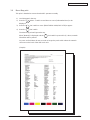
3.6 Menu Map print....................................................................................................................64
3.7 Connection methods............................................................................................................65
3.8 Confirmation of paper used by the user...............................................................................67
4. REPLACEMENT OF PARTS...............................................................................68
4.1
4.2
Precautions on the replacement of parts.............................................................................68
Part replacement methods...................................................................................................70
4.2.1 Left side cover..............................................................................................................70
4.2.2 Right side cover...........................................................................................................71
4.2.3 Detachment methods of the scanner and printer.........................................................72
44158801TH Rev.3
/
Oki Data CONFIDENTIAL
4.2.4 Scanner........................................................................................................................73
4.2.4.1 ADF Unit...............................................................................................................73
4.2.4.1.1 ASS'Y STOPPER.........................................................................................73
4.2.4.1.2 ASS'Y PAPER SUPPORT............................................................................73
4.2.4.1.3 ASS'Y PAPER TRAY.................................................................................... 74
4.2.4.1.4 ADF ROLLER............................................................................................... 74
4.2.4.1.5 ASS'Y PAD...................................................................................................75
4.2.4.1.6 ASS'Y HINGE LIGHT/HEAVY......................................................................76
4.2.4.1.7 ADF LEVER RELEASE................................................................................77
4.2.4.1.8 ASS'Y ADF DOCUMENT (with Hinge).........................................................78
4.2.4.2 Flatbed unit...........................................................................................................79
4.2.4.2.1 ASS'Y CONTROL PANEL............................................................................79
4.2.4.2.2 ASS'Y MAIN BOARD, ASS'Y STAND-L, R.................................................80
4.2.4.2.3 ASS'Y FLATBED UNIT.................................................................................83
4.2.5 Printer...........................................................................................................................84
4.2.5.1 Face-Up Tray........................................................................................................84
4.2.5.2 Rear cover.............................................................................................................85
4.2.5.3 LED Assy/LED Assy springs.................................................................................86
4.2.5.4 Control PCB..........................................................................................................87
4.2.5.5 Print engine controller PCB...................................................................................88
4.2.5.6 Top cover assembly..............................................................................................90
4.2.5.7 Top cover..............................................................................................................91
4.2.5.8 Controller Panel Assy...........................................................................................92
4.2.5.9 Board PRP/ Top Cover Handle.............................................................................93
4.2.5.10 Low-Voltage Power Supply / Low-Voltage Fan / Hopping Motor / Fuser Motor....94
4.2.5.11 Guide Eject Assy / Color Register Assy / Board-PRY..........................................96
4.2.5.12 Fan (Fuser)/ Belt Motor / High-Voltage Power Supply Board / Cover-Open Switch.... 98
4.2.5.13 MPT Assy..............................................................................................................99
4.2.5.14 Feeder Unit / Board-RSF/ MPT Hopping Roller / Frame Assy Separator / Cover Front...100
4.2.5.15 Board-PRZ Lift-Up Motor/Solenoid/Paper-End Sensor...................................... 101
4.2.5.16 Feed Roller.........................................................................................................103
4.2.5.17 Shaft Eject Assy(FU) / Shaft Eject Assy(FD) / Eject Sensor..............................104
4.2.5.18 Fuser Unit............................................................................................................105
4.2.5.19 Belt Unit..............................................................................................................106
4.3 Lubricating points...............................................................................................................107
4.4 Precautions for Main Board Replacement.........................................................................126
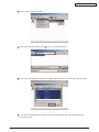
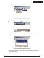
4.4.1 Deleting e-mail addresses.........................................................................................126
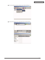
4.4.1.1 Steps of exporting and deleting data..................................................................126
4.4.1.2 Steps of importing the exported data..................................................................129
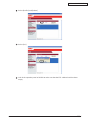
4.4.2 Deleting Server Profiles............................................................................................. 131
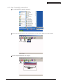
4.4.2.1 Steps of exporting and deleting data.................................................................. 131
4.4.2.2 Steps of importing the exported data..................................................................134
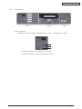
5. PANEL SWITCH FUNCTIONS..........................................................................136
5.1
Scanner Operator Panel ...................................................................................................136
5.1.1
Layout.........................................................................................................................136
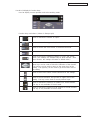
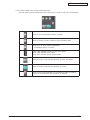
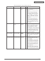
5.1.1.1 Buttons . .............................................................................................................136
5.1.2 LED/LCD....................................................................................................................138
5.1.3 Control Panel.............................................................................................................139
44158801TH Rev.3
/
Oki Data CONFIDENTIAL
6. MAINTENANCE MENUS...................................................................................142
6.1
6.2
6.3
System maintenance menu (For maintenance personnel).................................................142
Maintenance utility.............................................................................................................145
Functions of user's maintenance menu.............................................................................149
6.3.1 Maintenance menu (For end users)...........................................................................149
6.3.2 Self-diagnostic mode.................................................................................................150
6.3.2.1 Operator panel....................................................................................................150
6.3.2.2 Normal self-diagnostic mode (Level 1)...............................................................153
6.3.2.2.1 Activation method for self-diagnostic mode (Level 1) ...............................154
6.3.2.2.2 Deactivation of self-diagnostic mode.........................................................154
6.3.2.3 Switch scan test..................................................................................................154
6.3.2.4 Motor clutch test..................................................................................................157
6.3.2.5 Test print.............................................................................................................159
6.3.2.6 Color registration adjustment test.......................................................................164
6.3.2.7 Print density adjustment test...............................................................................165
6.3.2.8 Indication of consumable part counters..............................................................167
6.3.2.9 Indication of printed page counters.....................................................................168
6.3.2.10 Factory/Shipping switching . ..............................................................................168
6.3.2.11 Setup of self-diagnostic function.........................................................................169
6.3.2.12 Indication of LED head serial number................................................................. 170
6.3.2.13 Details of panel indications................................................................................. 171
6.3.3 Various types of print on the individual printer equipped with controller....................182
6.3.4 Functions of keys when depressed at power-on........................................................182
6.4 Setup after replacement of parts........................................................................................183
6.4.1 Precautions on the replacement of engine control PCB............................................183
6.4.2 Setup of EEPROM after replacement of TBR/TB2-6 PCB........................................186
6.4.2.1 Replacement of EEPROM after replacement of TBR/TB2-6 PCB.....................186
6.4.2.2 Setup of CU Serial Number................................................................................186
6.4.3 Setup of destination...................................................................................................187
6.6 Updating Scanner Firmware..............................................................................................188
6.6.1 Updating with the OKI MFP Network Setup Tool.......................................................188
6.6.2 Updating by Running the Scanner in Loader Mode................................................... 191
6.7 Adjustment of scanner after replacement of scanner main board.....................................193
7. PERIODICAL MAINTENANCE..........................................................................196
7.1
7.2
7.3
7.4
7.5
7.6
Recommended replacement parts.....................................................................................196
Cleaning.............................................................................................................................196
Cleaning of LED lens array................................................................................................196
Cleaning of pickup rollers...................................................................................................198
Internal cleaning of printer . ...............................................................................................199
Preventive Maintenance.....................................................................................................201
7.6.1 Cleaning the document glass.....................................................................................201
7.6.2 Cleaning the ADF.......................................................................................................202
7.6.3 Cleaning a Paper Jam . .............................................................................................202
7.6.4 Replacing the ADF pad..............................................................................................203
44158801TH Rev.3
/
Oki Data CONFIDENTIAL
8.TROUBLESHOOTING PROCEDURES.............................................................204
8.1
8.2
8.3
8.4
8.5
Precautions prior to repair..................................................................................................204
Items to be checked prior to taking action on abnormal images........................................204
Precautions when taking action on abnormal images.......................................................204
Preparations for troubleshooting........................................................................................204
Troubleshooting method.....................................................................................................204
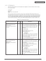
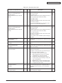
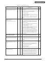
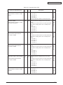
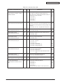
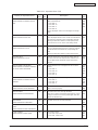
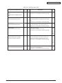
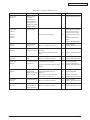
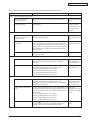
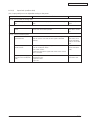
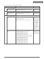
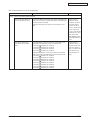
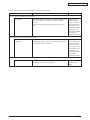
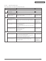
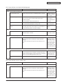
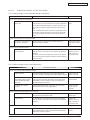
8.5.1 LCD Message List......................................................................................................205
8.5.2 Preparing for troubleshooting.....................................................................................221
8.5.3 Image Problem Troubleshooting................................................................................259
8.5.4 Actions after forced initialization of HDD/Flash.........................................................266
8.5.5 Network Troubleshooting...........................................................................................267
8.6 Check of fuses...................................................................................................................268
8.7 Troubleshooting..................................................................................................................269
Troubleshooting flowchart..........................................................................................269
8.7.1
8.7.1.1 Power ON to the MFP ready...............................................................................269
8.7.1.2 Copy operation ..................................................................................................270
8.7.1.3 Email operation...................................................................................................271
8.7.1.4 Control panel operation......................................................................................272
8.7.2 Tables.........................................................................................................................273
8.7.2.1 LCD does not display.......................................................................................... 274
8.7.2.2 Printer does not react.......................................................................................... 274
8.7.2.3 Scanning is not performed.................................................................................. 274
8.7.2.4 Printer does not print...........................................................................................275
8.7.2.5 Image unclear.....................................................................................................275
8.7.2.6 Noise generated..................................................................................................275
8.7.2.7 LCD does not show message after command....................................................275
8.7.2.8 MFP is not connected to the network.................................................................276
8.7.2.9 MFP cannot send email......................................................................................276
8.7.2.10 Error message (LCD of scanner)........................................................................277
8.7.2.10.1 Error message during initializing................................................................277
8.7.2.10.2 Error message during printing and copying...............................................278
8.7.2.10.3 Information codes during networking ........................................................283
8.7.2.10.4 Error message during E-mailing.................................................................285
8.7.2.10.5 Error message during filing........................................................................287
8.7.2.10.6 Error message on fax.................................................................................289
8.8 Scanner Shipment Setting List...........................................................................................290
8.8.1 The outline of Menu structure....................................................................................290
8.8.2 Scanner operation panel............................................................................................290
8.8.3 Menu Settings............................................................................................................294
8.8.4 Additional Settings.....................................................................................................297
8.8.5 Fax Service Mode......................................................................................................298
8.9 How to distinguish a Plus version unit...................................................................299
9.CONNECTION DIAGRAMS...............................................................................300
9.1
9.2
Check of resistance values................................................................................................300
Component layout..............................................................................................................304
44158801TH Rev.3
/
44158801TH Rev.3
3
C-2
C-1
10
10
11
11
C-3
Hopping Solenoid
Paper-end Sensor
5
Duplex
Connector
WR Sensor
IN1 Sensor
IN2 Sensor
Board-RSF
(Front Sensor)
F-5
F-3
2
2
2
4
(24V)
8
F-2
2
5
5
2
Board-V7Y-2
(Duplex Control)
PSU Fan Motor
3
Board-PRF
(PU)
10
10
C-6
4
C-4
2nd Tray
Connector
22
2
3
5
7
11
Hopping
Motor
ID Motor
2
C-14 C-14
M
Y
2
2
13
22
C-8
14
20
F-6
12
8
C-5
12
4
F-7
4
F-8
10
3
8
4
3
20
(USB)
F-12
F-11
F-10
F-9
C-HEAD
C-11
AC
C-12
CU Fan Motor
Centronics I/F
(option)
M-HEAD
Y-HEAD
K-HEAD
32 Board-TBI
24
24
24
24
Fuser Motor
C-10
Exit Sensor
Scanner Connector
Scanner I/F
3
32
5
24
24
24
24
Belt Motor
Lift Up Motor
4
C-9
9
5
5
Board-PRY
(Relay)
4
Board-TBR/TB2-6
(CU)
4
20
4
Density
Sensor
Thermistor
Fuser Fan Motor
Power Supply Unit
Board-V7Y
(2nd Tray Control)
9
C-7
F-4
3
Lift Up
2
Sensor
Board-PRC
(Registration Sensor)
High Voltage
Power Supply
Environment Sensor
13
2
C-13
C
K
C-13
Board-LUM
(RFID)
Board-PRZ
(Toner-low Sensor)
Board-POL
(RFID)
Cover Open SW
2
4
2
4
Fuser Connentor
FFC
Cable
Thermistor
(Upper)
Fuse
Thermistor
(Frame)
Thermistor
(Lower)
Heater Lamp
(x2)
1.1
11
7
Board-PRP
(Opepanel)
Oki Data CONFIDENTIAL
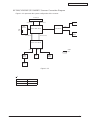
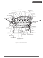
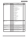
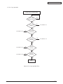
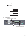
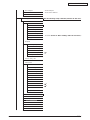
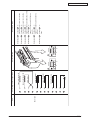
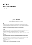
1.CONFIGURATION
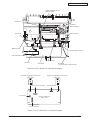
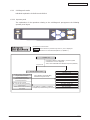
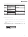
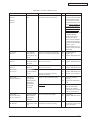
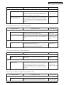
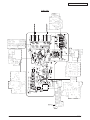
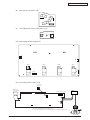
System configuration
MC560/CX2033MFP/ES5460MFP Printer Connection diagram
Figure 1-1-1 represents the system configuration of the printer.
Figure 1-1-1
/
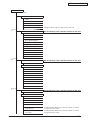
Oki Data CONFIDENTIAL
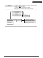
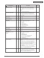
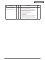
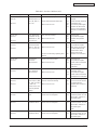
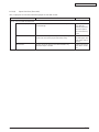
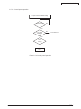
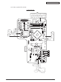
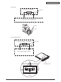
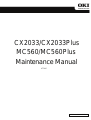
MC560/CX2033MFP/ES5460MFP Scanner Connection Diagram
Figure 1-1-2 represents the system configuration of the scanner.
Printer I/F
Printer Connector
Power (4 Pin)
USB (5 Pin)
FAX
Board
LINE
TEL
Motor
4 Pin
Scanner Main board
ADF Board
6 Pin
Paper
sensor
Motor (18 Pin)
CCD (20 Pin)
Scanner CCD board
4 Pin
2 Pin
Cable
3 Pin
FFC
Inverter
Circuit
Motor
Home
sensor
Lamp
Figure 1-1-2
1
Scanner
NonPlus
Plus
44158801TH Rev.3
Pin num.
34 Pin
40 Pin
/
Oki Data CONFIDENTIAL
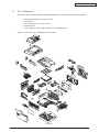
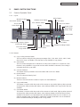
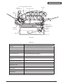
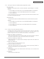
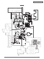
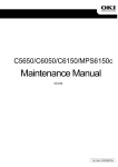
1.2
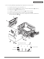
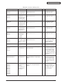
MFP configuration
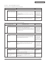
The internal part of the MC560/CX2033MFP/ES5460MFP is composed of the following sections:
•
•
•
•
•
Electrophotographic processing section
Paper paths
Control sections (CU sect./PU sect.)
Operator panel
Power supply sections (High-voltage sect./low-voltage sect.)
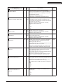
Figure 1-2 represents the configuration of the printer.
Air flow
Figure 1-2
44158801TH Rev.3
10 /
Oki Data CONFIDENTIAL
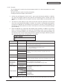
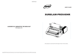
1.3
Composition of optional items
The following optional items are available for the printer:
(1)
Second tray
(2)
Duplex Unit
DXU-C4D
(3)
Expansion Memory 256 MB / 512 MB
MEM256E
MEM512C
For long printing, it is recommended to add an expansion memory.
(4)
Hard disk
HDD-C1B
44158801TH Rev.3
11 /
Oki Data CONFIDENTIAL
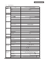
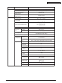
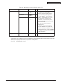
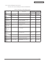
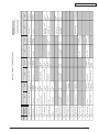
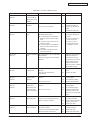
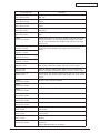
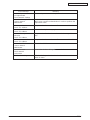
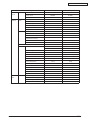
1.4
Specifications
Category
Exterior
Dimension
Item
MC560/CX2033MFP/ES5460MFP
Width
500mm
Depth
600mm
Height
575mm
Weight
about 37kg
Width of print
Width of print
A4
Engine speed
(A4)
Monochrome
32ppm
Color
20ppm
Fast print time
(A4)
Monochrome
8sec
Color
11sec
Warm-up time
60sec
Low noise mode
Resolution
LED head
Maximum input resolution
Output resolution
Step
Economic mode
CPU
Core
toner saving by lowering light
PowerPC750CXr
32KB (Internal L2:256KB)
500MHz
Bus width
64bit
Resident
256MB
Program
Power
Consumption
Power input
Power saving mode
256/512MB DIMM
64MB
110-127VAC (Range 99-140VAC)/
220-240VAC (Range 198-264VAC)
Below 27W
Idle
110W
Normal operation
490W
Peak
1200W
In operation
10 -32 , 17 -27
(temperature at full color printing with quality guaranteed)
At stand-by
0 -43 , power off
In storage (1 year max.)
-10 -43 , with drum and toner
At transport (1 month max.)
-29 -50 , with drum and without toner
At transport (1 month max.)
-29 -50 , with drum and toner
In operation
At stand-by
44158801TH Rev.3
4 step 600 x 600dpi
D-cash
ROM
Operation
Environment
(humidity)
600 x 1200dpi
True 600 x 1200dpi
True 600 x 600dpi
32KB
Option
Operation
Environment
(temperature)
600dpi
I-cash
Clock
RAM
Unavailable
20%-80%, 50%-70%
(humidity at fullcolor printing with quality guaranteed)
Max. wet bulb temperature : 25
10%-90%, Max. wet bulb temperature : 26.8
off
with power
In storage
10%-90%, Max. wet bulb temperature : 35
At transport
10%-90%, Max. wet bulb temperature : 40
12 /
Oki Data CONFIDENTIAL
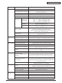
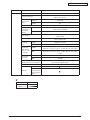
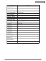
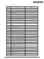
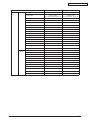
Category
Service life
Item
Printer life
420,000 pages, 5 years
Print duty (M=L/12, A=L/12/5)
Not applicable
MPBF
40,000 pages
MTTR
20 minutes
Starter toner
(Appended)
With 1st new
drum
Approx. 7,200 pages (black)
Approx. 5,200 pages (color)
Image drum life
Approx. 20,000 pages (With 3 pages / job)
Approx. 12,000 pages (With 1 pages / job)
Approx. 27,000 pages (When printed continuously)
Drum counter automatically reset
Tranfer belt life
60,000 pages (size A4, with 3 pages/job), counter
automatically reset
Fuser unit life
60,000 pages (size A4) counter automatically reset
In operation (ISO 7779 front)
Printing on one side
Paper handling Paper capacity (1st tray)
Paper capacity (2nd tray)
Paper capacity (Manual/auto)
37dB(A)
Backgrand level
Legal/universal cassette : 300 sheets (70kg)
Legal/universal cassette(Optional) : 530 sheets (70kg)
Standard multi-purpose tray : 50 OHP sheets or 100 sheets
of paper (70kg) or 10 envelopes
250 sheets (70kg)face-down/100 sheets (70kg)face-up in
tray
Duplex
Optional
Legal/universal or
A4-size cassette/ Universal
cassette
Two-sides
1st cassette:Legal13/13.5/14, letter, executive, A4, A5, B5, A6
2nd cassette:Legal13/13.5/14, letter, executive, A4, A5, B5
Reply-paid postcard (Max. 176gsm) (Multi-purpose tray)
Legal 13/13.5/14, letter, executive, A4, A5, B5, A6, C5,
DL, Com-9, com-10, Monarch, custom size, banners up to
1200mm (When paper length exceeds 356, its width shall
be from 210 to 215.9.)
Legal 13/13.5/14, letter, executive, A4, A5, Custom size
(Within permissible size and weight)
1st tray
105 x 148mm: A6
(Models for Japan [100 x 148: Pstcard size]
2nd tray
148x 210mm: A5
Manual & auto (MPT)
Two-sides
100 x 148mm: Postcard size
148 x 210mm: A5
1st tray
64-120gsm
2nd tray
64-176gsm
Manual & auto (MPT)
Two-sides
44158801TH Rev.3
Color mode : 57dB(A) or less (without option units)
Mono mode : 59.5dB(A) or less (without option units)
Delivery
Automatic front feeder or
manual feeder
Paper
thickness
Approx. 2,000 pages (black)
Approx. 1,500 pages (black)
Approx. 2,000 pages (color)
Approx. 1,500 pages (color)
Approx. 8,000 pages (black)
Approx. 6,000 pages (color)
Power-save mode
Min. paper size
ODA
OEL, AOS
ODA
OEL, AOS
Standard
At stand-by
Paper size
Max. 50,000 pages / mo.
Average 4,000 pages / mo.
MTBF (2.3% duty)
Toner life
(5% duty)
Operation
noise
MC560/CX2033MFP/ES5460MFP
64-203gsm OHP sheets available
64-105gsm
13 /
Oki Data CONFIDENTIAL
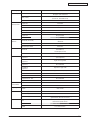
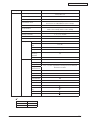
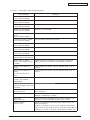
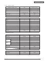
Category
Operator panel
Item
LCD
LED (Color)
Switch
Status
switch/sensor
16 characters in 2 line (Roman alphabet/Japanese kana)
No paper size indicated
Two
(Green x1, dark amber x1)
Six
Paper out
Provided
Paper low
Not provided
Toner low
Provided (Y.M.C.K)
Cover open
Provided
Fuser unit temp.
Provided
Paper size
Not provided
Stacker full
Not provided
Communication
Standard (On PCB)
interface
• Hi-Speed USB
• Ethernet
Additional Function
Not available
Input/output switch
Automatic
Emulation
Standard
Emulation switch
Font
MC560/CX2033MFP/ES5460MFP
PCL (PCL5c, HP-GL) / PCL XL2.1 SIDM (IBM-PPR,
EPSON-FX)
PostScript (Clone)
Automatic
Bit map
Type face
Agfa
1(Line printer)
Scalable 1
Type face
Agfa micro-type 86
Scalable 2
Type face
Not available
Scalable 3
Type face
Agfa micro-type 136
Rasterizer
Agfa UFST 4.0 (PCL)
Bar code
USPS
OCR
OCR-A, B
Japanese PCL font
Not available
Japanese PS font
Not available
Option
(Removable)
RAM set
256MB/512MB
HDD
2.5” IDE HDD
Shipping setup
Japan
GDI model
Others
USB-IF logo
Available
Windows logo
Available
Operation by UPS
Flatbed
44158801TH Rev.3
Operation by UPS (outage free power supply) is not
guaranteed. (Do not use UPS)
Life
50,000 scans or 5 years
More than 10,000 hours
MTBF
More than 5,000 hours
MTTR
Less than 30 min
14 /
Oki Data CONFIDENTIAL
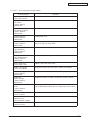
Category
ADF
Item
Life
240,000 scans or more, or 5 years
Recommended daily scans
Copy
Up to 1,000 pages a day
Recommended Pad
Replacement
50,000 scans
Recommended Roller
Replacement
200,000 scans
Color: 600 x 600dpi
Mono: 600 x 600dpi
Copy Resolution
Color: 12cpm (A4)
Mono: 20cpm (A4)
Copy Speed
First Copy Out Time (FCOT)
Duplex Copy
Document
Size
Flatbed
ADF
Calibration for color copy
Reductions/
Enlargement
Copy Feature
ADF Color: 23 sec.
Mono: 16 sec.
FB Color: 27 sec.
Mono: 19 sec.
No
Color Adjustment
Manual
Letter, A4, A5
Letter, A4, A5, Legal 14
Yes
(with Network Setup Utility)
No
25-400%
1% Increment
Preset Scalling
ODA: 25, 50, 78, 98 (Fit to page), 100, 127, 200%
OEL: 25, 50, 70, 98 (Fit to page), 100, 141, 200%
Copy Mode
Speed, Text, Photo
Photo/ text
separation
No
Morie Remove
No
Background
Remove
No
Density (Contrast)
-2, -1, 0, +1, +2
Number of
Copies
1-99
Collate
Yes
Edge Erase
ODA: 0-1in
OEL: 0-25mm
Margin shift
Left/Bottom side
ODA: 0-1in
OEL: 0-25mm
N-up
Banner Copy
44158801TH Rev.3
MC560/CX2033MFP/ES5460MFP
4-up
No
15 /
Oki Data CONFIDENTIAL
Category
Item
Scan
Scanner Type
MC560/CX2033MFP/ES5460MFP
Flatbed
Scanning Element
Auto Document Feeder
(ADF)
image sensor: Color CCD
light source: CCFL
Simplex
Yes (face up)
50 sheets
Duplex
No
Warm-up Time
90s
4800 x 4800dpi
Optical: 600 x 1200dpi
Resolution
(Selectable
on scanner
driver)
Optical
1200 x 1200dpi
Input: 48bit
Output: 24bit
Color Depth
Color: 10ppm (A4)
Mono: 20ppm (A4)
Scanning Speed
Scanning
Area
Platen
21.59cm x 29.72cm
ADF
21.59cm x 35.56cm
Document
Size (Selectable on scanner driver)
Platen
Business Card (4 x 2.5in),
Photo (5 x 3.5, 3.5 x 5, 6 x 4, 4 x 6in), B5, A5, A4, Letter
ADF
Business Card (4 x 2.5in),
Photo (5 x 3.5, 3.5 x 5, 6 x 4, 4 x 6in), B5, A5, A4, Letter,
Legal
Document/
thickness
Platen
20mm
ADF
16-28lb
File Format (Selectable image
file format on Scanner utilities)
Driver Interface
Features
BMP, PDF, TIFF, JPEG
(by ScanSoft PaperPort V9)
TWAIN, WIA
CIFS
1
Direct faxing
by addressing
<Fax number>
@fax
1
1
Scanner
Yes/No
NonPlus
No
Plus
Yes
44158801TH Rev.3
16 /
Oki Data CONFIDENTIAL
Category
Item
FAX
MC560/CX2033MFP/ES5460MFP
Connentivity
JP11 x 2 (Line/TEL)
PSTN, PBX Line
Compatibility
ITU-T G3 (Super G3)
Modem Speed
33.6Kbps
Transmission Time
ECM
3sec./Page
Document: ITU-T#1/MMR/Std (200 x 100dpi)
Yes
Std: 200 x 100dpi, Fine: 200 x 200dpi,
Photo: 200 x 200dpi, ExFine: 200 x 400dpi
Fax Resolution
Cording
MH, MR, MMR (def)
Density (Contrast)
-2, -1, 0, +1, +2/def0
Document Size
Letter, Legal, A4
TX/RX Memory Size
Dialing
Ten-key dial
Yes (Stored Dial)
One-Touch
dial
Yes (10)
Speed dial
200 location (max. 32 digits each location)
Group
Features
4.0MB
max. 20 groups
Speed dial
seach by
alphabet
Yes
Mixed Dial
Yes
Feeder TX
N/A
Memory TX
Yes
Delayed TX
Delayed
Broadcast TX
Broadcast TX
max. 5 TX time registration of Delayed TX and Delayed
Broadcast TX total.
max. 100 station
Auto RX
Yes
Manual RX
Yes
Real-Time RX
N/A
Memory RX
Yes
Auto Redial
Yes
Protocol Dump
2
Fax Forwarding
2
PC-Fax
2
DRD
2
2
Scanner
Yes/No
NonPlus
No
Plus
Yes
44158801TH Rev.3
17 /
Oki Data CONFIDENTIAL
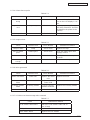
1.5
Interface specifications
1.5.1
Parallel interface specifications (N/A)
1.5.2
USB interface specifications
1.5.2.1 Outline of USB interface
(1) Basic specifications
USB (Hi-Speed USB supported)
(2) Transmission mode
Full speed (Max. 12Mbps ± 0.25%)
High speed (Max.480Mbps ± 0.05%)
(3) Power control
Self power device
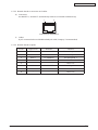
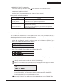
1.5.2.2 USB interface connectors and cables
(1) Connector
• Printer side: B-receptacle (Female)
Upstream port
2
1
3
4
Connector pin assignment
• Cable side: B-plug (Male)
(2) Cables
Cable length: Specification: USB2.0 type cables five meters long or shorter. Cables two
meters long or shorter are recommended. (Shielded cable lines shall be used.)
1.5.2.3 USB interface signals
44158801TH Rev.3
Signal name
Function
1
Vbus
Power supply (+5V)
2
D-
For data transfer
3
D+
For data transfer
4
GND
Shell
Shield
Signal ground
18 /
Oki Data CONFIDENTIAL
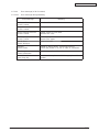
1.5.3
Network interface specifications
1.5.3.1 Outline of network interface
1.5.3.1.1 Basic specifications of network interface
Protocol family
TCP/IP
Network protocol
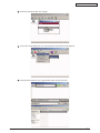
TCP, ARP, UDP
Application
LPR, RAW, FTP, Telenet
SNMPv1
DHCP/BOOTP
DNS
UPnP
SNTP
1.5.3.1.2 Basic specifications of network interface
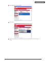
Protocol family
TCP/IP
Network protocol
IPv4, TCP, UDP, ARP
Application
LPR, RAW, FTP
SMTP/POP3
HTTP
Telenet
SNMPv1
DHCP/BOOTP
DNS
SNTP
44158801TH Rev.3
19 /
Oki Data CONFIDENTIAL
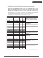
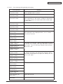
1.5.3.2 Network interface connectors and cables
(1) Connectors
100 BASE-TX / 10 BASE-T (Automatically switched, not usable simultaneously)
1
8
Connector pin assignment
2)
Cables
RJ-45 connectorized non-shielded twisted-pair cable (Category 5 recommended)
1.5.3.3 Network interface signals
Pin No.
Signal name
Direction
Function
1
TXD+
FROM PRINTER
Transmitting data +
2
TXD-
FROM PRINTER
Transmitting data -
3
RXD+
TO PRINTER
Receiving data +
4
-
-
Not in use
5
-
-
Not in use
6
RXD-
TO PRINTER
Receiving data -
7
-
-
Not in use
8
-
-
Not in use
44158801TH Rev.3
20 /
Oki Data CONFIDENTIAL
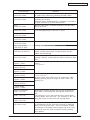
1.5.4
Telephone Line Interface Specification
1.5.4.1 Outline of telephone Line Interface
The machine will reliably communicate with distant stations over voice-level telephone line.
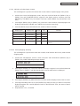
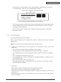
1.5.4.2 Telephone Line Interface Connector and Cable
Printer side : RJ-11
Cable side : TEL Cable (Cable with plug)
Connector contact arrengement
A1
A6
LINE
B1
B6
TEL
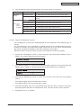
1.5.4.3 Telephone Line Interface signal
LINE
TEL
44158801TH Rev.3
Contact No.
Signal Name
A1
N/A
A2
T2-EX
A3
L1
A4
L2
A5
T1-EX
A6
N/A
B1
N/A
B2
N/A
B3
T2
B4
T1
B5
N/A
B6
EX
21 /
Oki Data CONFIDENTIAL
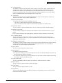
2.EXPLANATION OF OPERATION
2.1
Electrophotographic processing mechanism
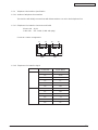
(1)
Electrophotographic process
The electrophotographic process is explained briefly below:
1. Charging
A voltage is applied to the CH roller to electrically charge the surface of the OPC drum.
2. Exposure
The LED head radiates light onto the charged OPC drum in accordance with the image
signal. The electric charge of the radiated part of the OPC drum surface attenuates
depending on the intensity of the light, thus forming an electrostatic latent image on the
OPC drum surface.
3. Development
Charged toner adheres to the electrostatic latent image of the OPC drum by
electrostatic power, and forms a visible image on the OPC drum surface.
4. Transfer
Paper is placed over the OPC drum surface and an electric charge is applied to it from
the back side by the transfer roller, so that the toner image is transferred to the paper.
5. Drum cleaning
The drum cleaning blade removes toner remaining on the OPC drum after the transfer.
6. Removal of Electricity
7. Belt cleaning
The belt cleaning blade removes toner remaining on the belt.
8. Fuser
Heat and pressure are applied to the toner image on the paper to promote its fusion.
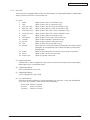
1. Charging
A voltage is applied to the charging roller, which is placed in contact with the OPC drum
surface, to charge the OPC drum surface.
Charging roller
Power
Supply
Unit
--
---
OPC drum
44158801TH Rev.3
22 /
Oki Data CONFIDENTIAL
2. Exposure
The light emitted from the LED head is radiated onto the charged surface of the OPC
drum. The charge of the radiated part of the OPC drum attenuates according to the
intensity of the light, forming an electrostatic latent image on the OPC drum surface.
LED head
Charging roller
Power
Supply
Unit
LED head
-- -
- -
OPC drum
Paper
OPC drum
3. Development
Toner adheres to the electrostatic latent image on the drum surface, thereby turning the
electrostatic latent image into a toner image.
1. The sponge roller allows the toner to stick to the development roller.
Charging roller
--
---
- -
OPC drum
Sponge roller
Development roller
2. The electrostatic latent image on the OPC drum surface is turned into a visible image by
the toner.
44158801TH Rev.3
23 /
Oki Data CONFIDENTIAL
4. Transfer
A sheet of paper is placed over the OPC drum surface, and an electric charge is given to
the paper from its back side by the transfer roller.
When a high voltage is applied to the transfer roller from the power source, the charge
induced on the transfer roller moves on to the surface of the paper through the contact
part between the transfer roller and the paper, the toner being attracted to the paper
surface from the OPC drum surface.
--
---
- -
OPC drum
Paper
- -+-+ -+-+ -+ -+ -+ +
- -+-+ -+
+
-+
-+
+
+
+
Transport belt
Transfer roller
Power
Supply
Unit
5. Drum cleaning
Unfixed toner remaining on the OPC drum is removed by the drum cleaning blade and
collected into the waste toner area of the toner cartridge.
Waste toner
Toner cartridge
ID unit
-
Drum cleaning blade
-+ -+ -+ -+ -+ -+ -+ -+ -+ -+
44158801TH Rev.3
-+
-+
24 /
Oki Data CONFIDENTIAL
6. Removal of Electricity
Electrically charge on the OPC drum surface decveases by exppsing the OPC drum
surface after transfer to the light.
Charging roller
Board for the light
of the removal of electricity
Light for the
removal of electricity
OPC drum
7. Belt Cleaning
Toner remaining on the transfer belt is scraped off by the belt cleaning blade and collected
into the waste toner box of the transfer belt unit.
Transport belt
Belt waste toner box
Belt cleaning blade
44158801TH Rev.3
25 /
Oki Data CONFIDENTIAL
8. Fuser
The toner image which was transferred to the paper is applied heat and pressure as it
passes between the heat roller and the backup roller, and it is therefore fused onto the
paper.
For the sake of safety, a thermostat is provided; it comes on to cut off the voltage supplied
to the heater if the heat roller temperature rises above a certain preset temperature.
Thermostat
Thermistor
Halogen Lamp
Heat Roller
Paper
Backup Roller
Pad
Beit
Thermistor
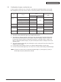
Fusing Temperature Settings
Paper thickness Paper Type Settings
Thin
Thick
44158801TH Rev.3
Temperature Settings
Light
Medium temp
Medium
High temp
Heavy
Medium temp
U.Heavy
Low temp
OHP
Low temp
26 /
Oki Data CONFIDENTIAL
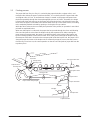
2.2
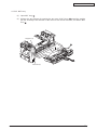
Printing process
The paper fed from Tray 1 or Tray 2 is carried by the paper feed roller, register roller L and
transport roller. When the paper is fed from the MPT, it is carried by the MPT paper feed roller
and register roller U. Then, an unfixed toner image is created on the paper transported onto
the belt sequentially through the electrophotographic process of KYMC. Thereafter, the image
is fixed under heat and pressure as the paper goes through the fuser unit. After the image has
been fixed, the paper is unloaded to the stacker either face-up or face-down stacker, according
to the outputting method selected by opening or closing the face-up stacker.
While the above refers to the one-sided print operation of the printer, its operation in two-sided
print will be explained below.
When two-sided print is conducted, the paper that has passed through the fuser unit following
first one-sided print is sucked into the Duplex unit by the separator DUP. After entering the
paper reversal transport path, the paper is carried from there to the inside of the Duplex unit
by the inverting operation of the reversal roller. Then, after passed through the Duplex unit by
the transport roller that is located on the transport path inside the Duplex unit, the paper is fed
along the paper feed route of the Duplex unit to eventually merge the same route that comes
from the tray. From here on, the same operation as that of one-sided print of paper fed from the
tray takes place.
n stacke
w
Face-do
Heat roller
Fac
e
-up
r
sta
MPT paper feed roller
Halogen lamp
cke
r
Backup roller
Transport belt
Separator DUP
Reversal roller
MPT
Register roller U
Belt
Transport roller
Register roller L
Paper reversal transport path
Paper feed roller
Subroller
Subroller
Transport roller
Paper feed roller
44158801TH Rev.3
27 /
Oki Data CONFIDENTIAL
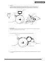
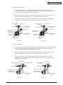
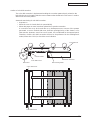
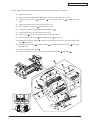
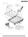
(1)
Paper fed from 1st Tray
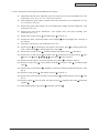
1. As illustrated in Figure 2-1, when the solenoid is ON, the register motor rotates
(Counterclockwise turn), transporting the paper until the IN1 sensor comes ON. (When
the solenoid is ON, the paper feed roller is driven.)
2. After causing the IN1 sensor to come ON, the paper is further carried over a certain
distance to finally hit register roller L. (This corrects skew of the paper.)
3. As shown in Figure 2-2, the solenoid is turned OFF and the paper is transported by
register roller L. (When the solenoid is OFF, register roller L is driven.)
Register Roller U
(Drive)
Register Roller U
(Drive)
IN2 Sensor
WR Sensor
Registration Roller L
(Stop)
IN1 Sensor
Solenoid Lever
(Solenoid OFF)
Registration Motor
(CCW)
Paper
Sub Roller
(Stop)
Registration Motor
(CCW)
Paper
Hopping Roller
(Stop)
Hopping Roller
(Drive)
Figure 2-1
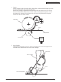
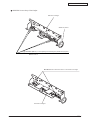
(2)
Registration Roller L
(Drive)
WR Sensor
IN1 Sensor
Hopping Gear Assy
Solenoid Lever
(Solenoid ON)
Sub Roller
(Drive)
IN2 Sensor
Figure 2-2
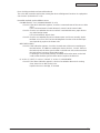
Paper fed from MPT
1. As illustrated in Figure 2-3, when the solenoid is OFF, the register motor rotates (Clockwise
turn), transporting the paper until the IN2 sensor comes ON. (As the register motor
rotates clockwise, the MPT paper feed roller is driven.)
2. After causing the IN2 sensor to come ON, the paper is further carried over a certain
distance to finally hit register roller U. (This corrects skew of the paper.)
3. As shown in Figure 2-4, the register motor rotates (Counterclockwise turn) to let
register roller U transport the paper. (As the register motor rotates counterclockwise,
register roller U is driven.)
IN2 Sensor
MPT Hopping Roller
Registration Roller U
(Stop)
WR Sensor
Paper
IN2 Sensor
Registration Roller U
(Drive)
WR Sensor
Hopping Gear Assy
Hopping Gear Assy
Solenoid Lever
(Solenoid OFF)
Solenoid Lever
(Solenoid OFF)
Registration Motor
(CW)
Figure 2-3
44158801TH Rev.3
Paper
Registration Motor
(CCW)
Figure 2-4
28 /
Oki Data CONFIDENTIAL
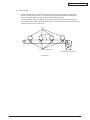
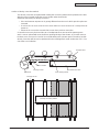
(3)
Transport belt
1. As the transport belt motor rotates in the direction of the arrow, the transport belt is
driven. The belt unit consists of one transport roller placed immediately underneath
each color drum, with a transport belt inserted in between them.
As the specified voltage is applied, the transport belt and the transport rollers send
the paper located on the transport belt to the fuser unit while transferring to it the toner
image present on each color drum.
Drum
Carrier belt
K
Y
M
C
Carrier (transfer) roller
Carrier (transfer) belt motor
Figure 2-5
44158801TH Rev.3
29 /
Oki Data CONFIDENTIAL
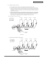
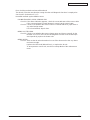
(4)
Up/down-motions of ID units
1. The up/down-motions of the ID units take place driven by the lift-up motor.
2. Figure 2-6 shows the motions of the different ID units when the printer is operated for
color print. As the lift-up motor rotates (Clockwise turn), the lift-up link slides to the left,
causing the ID units to come down, as can be seen in Figure 2-6. Namely, the printer
is readied for color print.
3. Figure 2-7 shows the motions of the different ID units when the printer is operated for
monochrome print. As the lift-up motor rotates (Counterclockwise turn), the lift-up link
slides to the right, causing the ID units to go up, except for the K-ID unit, as can be
seen in Figure 2-7. Namely, the printer is readied for monochrome print.
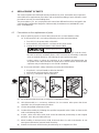
ID Unit Operations During Color Printing
C-ID Unit
M-ID Unit
Y-ID Unit
K-ID Unit
C-ID Unit down
M-ID Unit down
Y-ID Unit down
K-ID Unit down
Lift uplink
C-ID Motor
(CCW)
Figure 2-6
ID Unit Operations During Monochrome Printing
C-ID Unit
M-ID Unit
C-ID Unit lift up
M-ID Unit lift up
Y-ID Unit lift up
K-ID Unit down
Y-ID Unit
K-ID Unit
Lift uplink
Figure 2-7
44158801TH Rev.3
C-ID Motor
(CW)
30 /
Oki Data CONFIDENTIAL
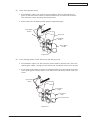
(5)
Fuser unit and paper output
1. As illustrated in Figure 2-8, the fuser unit and delivery roller are driven by the DC
motor. As the fuser motor rotates (Counterclockwise turn), the heat roller is turned.
This roller fixes a toner image by heat and pressure.
2. At the same time, the delivery roller rotates to output the paper.
Eject Roller
(Drive)
Fuser Unit
Heat Roller
(Drive)
Fuser Motor
(CCW)
Figure 2-8
(6)
Cover-opening motion of color drift sensor and density sensor
1. As illustrated in Figure 2-9, when the fuser motor rotates (Clockwise turn), the coveropening gear rotates, causing the color drift sensor and density sensor cover to open.
2. As the fuser motor rotates in reverse (Counterclockwise turn), the engagement of the
cover-opening gear is freed, and the color drift sensor and density sensor cover now
closes.
Eject Roller
(Stop)
Heat Roller
(Stop)
Fuser Motor
(CW)
Cover Open Gear
Figure 2-9
44158801TH Rev.3
31 /
Oki Data CONFIDENTIAL
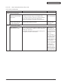
Outline of color drift correction
The color drift correction is implemented reading the correction pattern that is printed on the
belt with the sensor located inside the sensor shutter under the belt unit. This sensor is used to
detect and correct the pattern.
Automatic start timing of color drift correction:
• At power-on
• When the cover is closed after it is opened briefly
• When 400 pages or more have been printed since previous execution
A correction error may be issued due to an inadequate toner amount of the pattern
generated, a sensor stained with toner, deficient opening/closing of the shutter, or for
other reasons. However, even if an error is issued, it is not indicated on the operator panel.
Therefore, forcible color drift correction will have to be performed in the self-diagnostic
mode (Subsection 5.3.2.6) to check the error indication.
Transport belt
Sensor shutter
Belt waste toner box
Color drift sensor
Belt cleaning blade
Belt motor
Color drift sensor
Right color drift correction pattern
Left color drift correction pattern
Color drift sensor
44158801TH Rev.3
32 /
Oki Data CONFIDENTIAL
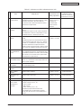
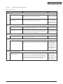
Error checking methods and remedial methods
The color drift correction test function among the other self-diagnostic functions is employed to
check errors. (Subsection 5.3.2.6)
Remedial methods against different errors
• CALIBRATION (L or R), DYNAMICRANGE (L or R)
Check 1: If the above indication appears, check the connected state of the sensor cable
(FFC).
If the connected state is found abnormal, restore it to the normal state.
Check 2: Check to see whether the sensor surface is stained with toner, paper dust or
any other foreign matter.
If it is found stained, wipe it clean.
Check 3: Check to see whether the sensor shutter opens and closes normally, by the
MOTOR & CLUTCH TEST of the self-diagnostic function. If the shutter operates imperfectly, replace the shutter unit.
• BELT REFLX ERR
Check 4: If this indication appears, check the cleaned state of the toner remaining on
the belt surface, in addition to making the above checks 1, 2 and 3. Take out
the belt unit, turn the drive gear located on the left rear side, and ensure that
the belt surface has been cleaned thoroughly.
If cleaning is not achieved perfectly and there still remains toner on the belt
surface after the drive gear has been turned, replace the belt unit.
• (Y or M or C) LEFT, (Y or M or C) RIGHT, (Y or M or C) HORIZONTAL
Check 5: If the above indication appears, check to see whether the toner is running
short, based on an NG-issuing color.
Replace the toner cartridge, as needed.
44158801TH Rev.3
33 /
Oki Data CONFIDENTIAL
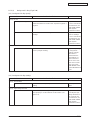
Outline of density correction method
The density correction is implemented reading the correction pattern that is printed on the belt
with the sensor located inside the sensor shutter under the belt unit.
Automatic start timing of density correction:
•
•
•
If the environment at power-on is greatly different from the one in which previous print was
executed.
If at least one or more of the four ID count values are close to those of a new product at
power-on.
When the ID count value exceeds 500 counts since previous execution.
A correction error may be issued due to an inadequate toner amount of the pattern generated, a sensor stained with toner, deficient opening/closing of the shutter, or for other reasons.
However, even if an error is issued, it is not indicated on the operator panel. Therefore, forcible
density correction will have to be performed in the self-diagnostic mode (Subsection 5.3.2.7) to
check the error indication.
Transport belt
Sensor shutter
Belt waste toner box
Density sensor
Belt motor
Belt cleaning blade
Density sensor
Density correction pattern
44158801TH Rev.3
34 /
Oki Data CONFIDENTIAL
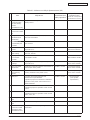
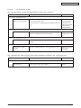
Error checking methods and remedial methods
The density correction test function among the other self-diagnostic functions is employed to
check errors. (Subsection 5.3.2.7)
Remedial methods against different errors
• CALIBRATION ERR, DENS SENSOR ERR
Check 1: If the above indication appears, check the connected state of the sensor cable.
If the connected state is found abnormal, restore it to the normal state.
Check 2: Check to see whether the sensor surface is stained with toner, paper dust or
any other foreign matter.
If it is found stained, wipe it clean.
• DENS SHUTTER ERR
Check 3: Check to see whether the sensor shutter opens and closes normally, by the
MOTOR & CLUTCH TEST of the self-diagnostic function. If the shutter operates imperfectly, replace the shutter unit.
• DENS ID ERR
Check 4: Take out the ID unit and examine it to see if the drum surface has any abnormal toner smudge.
Replace the LED head (Blurred focus), or replace the ID unit.
To test-operate a new ID unit, use the Fuse Keep Mode of the maintenance
menu.
44158801TH Rev.3
35 /
Oki Data CONFIDENTIAL
Principle of toner sensor detection
Toner LOW is detected by the toner sensor (Reflection sensor) installed inside the printer. The
shielding plate is mounted inside the ID and rotates in synchronization with toner agitation.
Moreover, the ID has a shutter fitted. The shutter is synchronized with the operation lever of
the toner cartridge, and the toner sensor can detect that the toner cartridge has been loaded
properly. Detection may not take place normally, and a toner sensor error may be issued, if
the shield plate or toner sensor is stained with toner, or if the ID unit and toner sensor do not
remain exactly opposite to each other in their positions.
Shutter
Shield plate
Toner Sensor
Principle of toner counter
After image data is developed to binary data which the printer can print, it is counted by an LSI
as a number of print dots. The amount of toner consumed is calculated from that count value,
and the remaining amount of toner is thus indicated. As opposed to this, the toner LOW detection by the toner sensor is implemented when the toner amount remaining inside the ID unit
physically decreases to below a certain level.
Principles of ID, belt and Fuser counters
One count represents the value that results from dividing the amount of rotation of the drum by three when three A4-size sheets are printed continuously.
Belt counter: One count represents the value that results from dividing the amount of rotation of the belt by three when three A4-size sheets are printed continuously.
Fuser counter: One count is registered when paper is shorter than the length of Legal 13-inch
paper. When paper is longer than that, the count number is determined by the
number of times the Legal 13-inch paper length is exceeded. (Decimal fractions rounded up)
ID counter:
44158801TH Rev.3
36 /
Oki Data CONFIDENTIAL
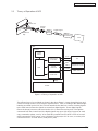
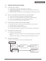
2.3
Theory of Operation of MFP
Cold
Fluorescent
Analog
Signal
Lens
Reflected
Ray
CCD
Main
Board
Digital Signal
Image
Processor
CPU
MFP
Scanner
Control
Panel
Scan
USB Device
Controller
RJ-45
Ethernet
CPU
Print
PC
Print
Filing
FTP/HTTP Server
E-mail
SMTP Server
USB Host
Copy
Printer
Figure 2.1 Theory of Operation of MFP
The reflected rays of your original as shown in the above Figure 2.1 pass through the lens and
creates an image on the CCD (Charged Coupled Device). Then, according to the different light
intensity perceived by the CCD, the CCD will transfer these data into a series of analog signals
to the main board, where the signals are turned into digital signals. These digital signals
flow to the image processor and store into the CPU (Central Processing Unit). Through the
commands from the Control Panel, the digital signals may go to USB host (copy port) to send
copy command to printer, or to RJ-45 to send filing command to FTP/HTTP server or to send
email command to SMTP server, or to USB device (USB port) to PC for scan, or receive print
command from PC via USB device (USB port for print).
44158801TH Rev.3
37 /
Oki Data CONFIDENTIAL
3.
INSTALLATION
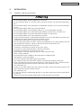
3.1
Cautions, and do's and don'ts
• Do not install the MFP at high temperature or near fire.
• Do not install the MFP in a location where chemical reaction can take place (laboratory,
etc.).
• Do not install the MFP in the proximities of inflammable solvents, such as alcohol, paint thinner, etc.
• Do not install the MFP within reach of small children.
• Do not install the MFP in an unstable location (e.g., on a rickety bench or grade).
• Do not install the MFP in a location laden with moisture or heavy dust, or in direct sun.
• Do not install the MFP in an environment with sea wind or corrosive gas.
• Do not install the MFP in a location with heavy vibration.
• In the event that the MFP is inadvertently dropped or its cover is damaged, remove the power plug from the power outlet and contact Customer Center.
Such mishap could lead to an electric shock, fire or injury.
• Do not connect the power cord, MFP cable or grounding wire in any other manner than the
way specified in the manual. Failure to observe the above could result in fire.
• Do not stick in an object into the vent hole.
Such action could lead to an electric shock, fire or injury.
• Do not place a glass filled with water or the like on the MFP.
Such action could lead to an electric shock or fire.
• When the MFP cover has been opened, do not touch the fuser unit.
Burns could be suffered.
• Do not throw the toner cartridge or the image drum cartridge into fire.
Dust explosion could cause burns.
• Do not use a highly combustible spray near the MFP.
Fire could be caused, since the MFP contains a part that gets extremely hot inside.
• In the event that the cover becomes unusually hot, emits smoke, ill odor, or abnormal noise,
remove the power plug from the power outlet and contact Customer Center.
Fire could break out.
• If water or any other liquid enters the inside of the MFP, remove the power plug from the
power outlet and contact Customer Center.
Fire could break out.
• If a pao not operate or disassemble the MFP in any other manner than the way specified in
the manual.
Failure to observe this warning could result in an electric shock, fire or injury.
44158801TH Rev.3
38 /
Oki Data CONFIDENTIAL
• Do not install the MFP in a location where its vent hole is blocked.
• Do not install the MFP directly on a shaggy carpet or rug.
• Do not install the MFP in a sealed room or other location with poor ventilation or permeability.
• Install the MFP away from a heavy magnetic field or noise source.
• Install the MFP away from a video monitor or TV.
• To move the MFP, hold it by both sides of it.
• This MFP, which weighs Approx. 37kg, should be lifted up by two or more persons.
• When the MFP has the power switched on or is printing, do not come close to the paper delivery section. Such action could lead to injury.
When the precautionary notes concerning the installation and operation are explained, the
user should be referred to the precautionary notes given in the User's Manual. Especially, give
thorough explanation on the power cord and grounding wire.
44158801TH Rev.3
39 /
Oki Data CONFIDENTIAL
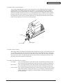
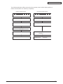
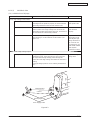
3.2
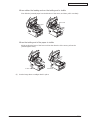
Unpacking method
Personal injuries may occur.
Make sure to lift up this MFP by two or more persons, since it weighs Approx. 37kg.
• Remove the four handles from the sides of the box, as illustrated below, and lift up the
corrugated fiberboard box.
44158801TH Rev.3
40 /
Oki Data CONFIDENTIAL
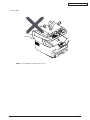
Moving MFP
Note! Do not hold the scanner unit to carry.
44158801TH Rev.3
41 /
Oki Data CONFIDENTIAL
3.3
MFP Installation Instructions
• Install the MFP in a location where the following temperature and humidity are met:
Ambient temperature: 10 - 32˚C
Ambient humidity: 20 - 80 %RH(Relative humidity)
Max. wet-bulb temperature: 25˚C
• Use caution to avoid dew condensation.
• If the MFP is installed in a location with ambient relative humidity below 30%, use a humidifier or antistatic mat.
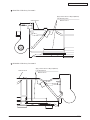
Installation space
• Place the MFP on a flat desk large enough to accommodate its footings.
• Provide ample spaces around the MFP.
Plan view
20cm
40cm
100cm
20cm
Side View
70cm
44158801TH Rev.3
42 /
Oki Data CONFIDENTIAL
3.4
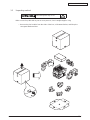
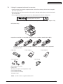
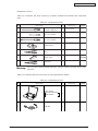
Listing of component units and accessories
• Check to make sure that the component units are free from damage, dirt or other zirregularities in the appearance.
• Ensure that none of the accessories to the units is missing and that they are free from breakage or other flaw.
• If any irregularity is discovered, contact User Management Section for instructions.
Personal injuries may occur.
Make sure to lift up this MFP by two or more persons, since it weighs Approx. 37kg.
MFP (Main body)
Image drum cartridges (4 sets) fitted with starter toner cartridges (Installed in the MFP)
Inform the user that the toner cartridges and image drum cartridges can be separated
one from the other.
Paper tray
Paper support
Core (4 pieces)
Paper stopper
Cable clamp
MFP software CD-ROM
Power cord
Warranty Card and User Registration Card
User's Manual (Setup)
User's Manual (CD-ROM)
TEL/LINE Cable
Note! No MFP cable is supplied with the MFP.
44158801TH Rev.3
43 /
Oki Data CONFIDENTIAL
3.5
Assembly Procedure
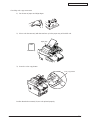
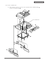
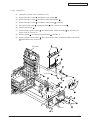
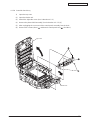
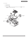
3.5.1
MFP main body
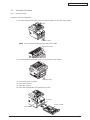
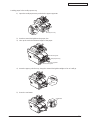
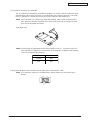
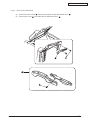
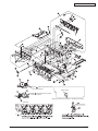
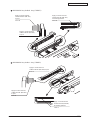
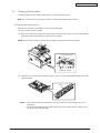
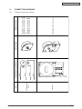
Remove Protective Equipment
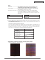
1) Remove the protective tape (5 places) and the paper on the front of the printer.
Paper
Protective Tape
Note! Do not remove the transparent sheet on the ADF.
Transparent sheet
2) Remove the protective tape (2 places) on the back of the printer.
Protective Tape
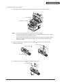
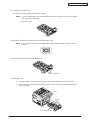
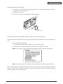
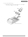
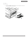
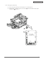
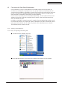
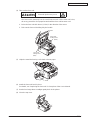
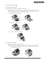
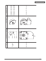
3)
4)
5)
6)
Pull out the paper cassette.
Pull out the retainer.
Open the scanner.
Press the OPEN button and open the top cover.
Retainer
Paper cassette
OPEN Button
44158801TH Rev.3
44 /
Oki Data CONFIDENTIAL
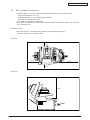
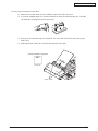
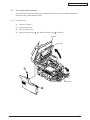
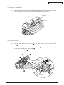
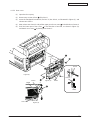
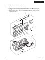
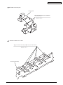
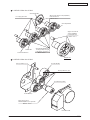
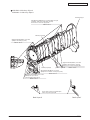
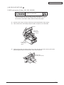
7) Hold down the fuser unit lever (blue) in the direction of the arrow
stopper-release (orange).
and remove the
Fuser unit lever (blue)
Stopper-release (orange)
Note!
44158801TH Rev.3
The stopper-release is necessary for printer transport. It should be kept.
45 /
Oki Data CONFIDENTIAL
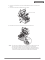
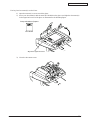
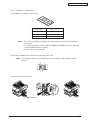
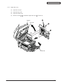
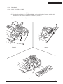
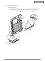
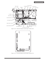
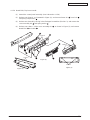
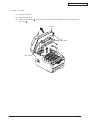
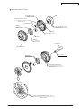
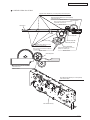
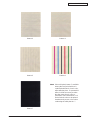
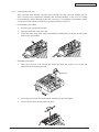
Install the image drum cartridges
1) Gently take out four image drum cartridges with starter toner cartridges installed.
Toner cartridge
Image drum cartridge
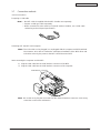
Note! • Do not move the blue levers of the starter toner cartridges.
• Handle the image drum cartridges (the green cylinder part of them) with enough
care because they are damaged very easily.
• Do not expose the image drum cartridges to direct sunlight or strong light (approx.
1500 lux or above). Even under room light, do not leave them exposed for five
minutes or longer.
2)
Remove the tape that is fixing the protective sheet
direction of the arrow.
, and pull out the sheet in the
Protective sheet
Protective sheet
Tape
Protective sheet
3)
Pull out the protective sheet
in the direction of the arrow.
Protective sheet
44158801TH Rev.3
46 /
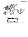
Oki Data CONFIDENTIAL
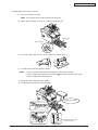
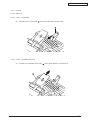
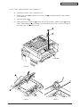
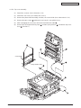
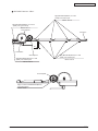
4) Check the color of the label on each toner cartridge against the label on each image drum
cartridge.
5) Gently set four image drum cartridges back into the printer.
Label
Image drum cartridge
Labels
6) Rotate the lever of each toner cartridge fully in the direction of the arrow.
Blue
Lever
Note! • The starter toner cartridges (the toner cartridges that come with the printer at the
time of purchase) can print approx. 1,500 A4 sheets in 5% print density.
• The starter toner cartridges can not be used again once replaced with ordinary
toner cartridges. Use up the starter toner cartridges first, and replace them with
ordinary toner cartridges respectively when [TONER EMPTY] is displayed.
44158801TH Rev.3
47 /
Oki Data CONFIDENTIAL
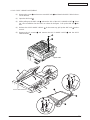
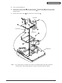
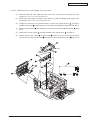
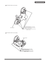
Install the parts of the scanner
1) Attach a paper tray, a paper support and a paper stopper.
Paper Tray
Paper Support
Paper Stopper
2) Open the ADF unit to release the lock.
ADF unit
44158801TH Rev.3
48 /
Oki Data CONFIDENTIAL
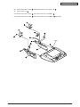
Loading paper in the paper cassette
1) Pull out the paper cassette.
Note! Do not peel off the rubber attached to the plate.
2) Set the paper stopper securely, according to the paper size.
Paper guide
Paper stopper
Plate
3) Loosen the paper well and line up its vertical and lateral edges.
4) Load the paper with the print face down.
Note! • Place the paper aligned to the forward end of the paper cassette.
• Load the paper by avoiding to exceed the ( ) mark of the paper guide. (300
sheets of 70kg ream weight paper).
5) Fasten the paper with the paper guides.
6) Put the paper cassette back into the MFP.
Print face down
mark
Paper guide
44158801TH Rev.3
Indication of remaining
amount of paper
49 /
Oki Data CONFIDENTIAL
Loading paper in the multi-purpose tray
1) Open the multi-purpose tray and also the paper supporter.
Multi-purpose tray
2) Set the manual feed guide to the paper size.
3) Line up the vertical and lateral edges of the paper.
Manual feed guide
Multi-purpose tray
Paper supporter
Manual feed guide
4) Insert the paper, print-face up, along the manual feed guide straight as far as it will go.
mark
5) Press the set button.
Set button
44158801TH Rev.3
50 /
Oki Data CONFIDENTIAL
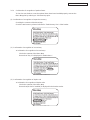
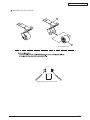
Placing Your Document(s) in the ADF
1) Make sure your document is free of staples, paper clips and is not worn.
2) If you have multiple pages, fan your document(s) to avoid occasional paper jam. The ADF
can hold up to 50-page document at one time.
3) Place your document(s) with your text FACE UP in the ADF and assure top of the pages
feed in first.
4) Adjust the Paper Guides to center the document(s) in the ADF.
Setup orientation of papers
ABC
R
LT
C
Face Up
AB
A5
A6
A4
B5
A6
A5
B5
A4
R
LT
Paper Guide
44158801TH Rev.3
51 /
Oki Data CONFIDENTIAL
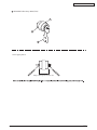
Placing Your Document(s) on the Glass
1) Open document(s) cover to reveal the glass.
2) Place your document(s) with the text FACE DOWN on the glass and align the document(s)
in the upper-left corner of the glass as illustrated in the following figure.
Setup orientation of papers
Face Down
Align in the upper-left corner
3) Close the document cover.
44158801TH Rev.3
52 /
Oki Data CONFIDENTIAL
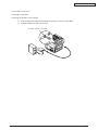
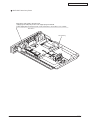
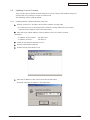
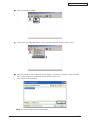
3.5.2
Connection of power cable
Power supply conditions
• Observe the following conditions:
AC: 110~127V±10%/220~240V±10%
Power frequency: 50Hz or 60Hz ± 2Hz Approx. 37kg
• If the available power is unstable, use a voltage regulator or the like.
• The maximum power consumption of this MFP is 1200W. Ensure that the power source offers an ample margin in the power capacity.
It may expose you to electric shocks or cause a fire.
• Always before connecting or disconnecting the power cord and grounding wire, first turn off
the power switch.
• The grounding wire should be connected to a grounding terminal. Do Not in any event tie it
to a water service piping, gas piping, ground of telephone lines, lightning arrester or the like.
• When plugging in or unplugging the power cord, be sure to hold the power plug.
• Insert the power plug securely into the power outlet as far as it will go.
• Do not insert or remove the power plug with a wet hand.
• Lay the power cord in a location where it is not likely stepped on, and avoid placing anything
on the power cord.
• Do not bundle or tie the power cord.
• Do not use a damaged power cord.
• Avoid a starburst connection of cables.
• Do not connect the MFP to the same power outlet shared by other electric appliances. Especially, if the MFP is connected to the same power outlet in conjunction with an air-conditioner, copy machine or shredder, electric noise may cause false operation of the MFP. If it is
inevitable to connect them to the same power outlet, use a commercial noise filter or noisecut transformer.
• Operate the MFP with the supplied power cord only.
• Do not use an extension cord. If it is inevitable to use an extension cord, use one with rating
of 15A or more.
• Use of an extension cord may hinder the MFP from operating normally because of voltage
drop.
• Do not turn off the power or pull out the power plug while the MFP is printing.
• If the MFP is going to be placed out of use for an extended period of time due to a long spell
of holidays or a trip out of town, unplug the power cord.
About the connections of the power cord and grounding wire, the user should be given thorough explanation on the basis of the User's Manual.
44158801TH Rev.3
53 /
Oki Data CONFIDENTIAL
Connecting the power cord
Note! Ensure that the power switch is in OFF (O).
1) Insert the power cord into the MFP.
2) Connect the grounding wire to the ground terminal.
3) Insert the power plug into the power outlet.
Ground terminal
O
Grounding wire
I
Pressing ON (|) of the power switch
O
44158801TH Rev.3
I
54 /
Oki Data CONFIDENTIAL
The following indication will be produced on the operator panel, and the display will be as
follows when the MFP has started up completely.
(Printer Operator Panel)
PLEASE WAIT
(Scanner Operator Panel)
Detecting Printer
RAM CHECK
INITIALIZING
ONLINE
44158801TH Rev.3
<<MC560>>
Initializing...
A4
Quality=Speed
Auto
Density=0
55 /
Oki Data CONFIDENTIAL
Checking color copy movement
1) Fan sheets of paper and align edges.
2) Place color document(s) with the text face up in the paper tray of the ADF unit.
Paper tray
C
AB
ABC
Text face up
3) Press the color copy button.
Color copy button
Confirm that the document(s) is/are color printed properly.
44158801TH Rev.3
56 /
Oki Data CONFIDENTIAL
Turning off the power
When a hard disk (optional) is not equipped, the power can be turned off as is.
O
I
Note! Do not turn off the power while the MFP is printing.
On the MC560/CX2033MFP/ES5460MFP equipped with the built-in type hard disk (optional),
do not outright turn off the power, but follow the procedure described below.
Note! • Abrupt disconnection of the power could damage the built-in hard type disk, disabling
it.
• [SHUTDOWN MENU] is displayed only when the MFP is equipped with the optional
built-in type hard disk.
(1) Press the
"Back" switch for four seconds or longer to cause [SHUTTING DOWN] to
appear.
(2) Press the
"Set" switch.
[SHUTDWN] is displayed, and the shutdown processing begins
(3) When [PLEASE POW OFF/SHUTDOWN COMP] shows up, press OFF (O) of the power
switch.
O
44158801TH Rev.3
I
57 /
Oki Data CONFIDENTIAL
3.5.3
Installation of optional items
(1) Installation of expansion memory set
Model name
Memory volume
None (Standard)
256MB(256MB)
MEM256E
+256MB(512MB)
MEM512C
+512MB(768MB)
(Total memory volume)
Note! • Be sure to use genuine Oki Data parts. If any other parts are used, the MFP will
not function.
• To conduct long print on the MC560/CX2033MFP/ES5460MFP, it is recommended
to add a 256MB expansion memory.
• There is only one memory slot.
Turning OFF the MFP power and disconnecting the power cord
Note! If an expansion memory is installed with the power switched ON, the MFP may be
broken.
O
I
Opening the cover-side-R(sub)
Cover-side-R(sub)
44158801TH Rev.3
58 /
Oki Data CONFIDENTIAL
(2) Installation of second tray unit
This tray is intended to increase the amount of paper that can be loaded in the MFP. It holds
530 sheets of 70kg ream weight paper, allowing to print 930 sheets continuously when combined with the standard paper cassette and multi-purpose tray.
Turning OFF the MFP power and disconnecting the power cord
Note! If an expansion memory is installed with the power switched ON, the MFP may be
broken.
O
I
Placing the MFP on the second tray unit.
Note! The MFP weighs Approx. 37kg. It should be lifted up by two or more persons.
1) Align the holes in the bottom of the MFP to the protrusions of the second tray unit.
2) Place the MFP gently on the second tray unit.
To detach the second tray unit, follow the same procedure inversely.
Holes in the printer bottom
Protrusions
2nd-piece
44158801TH Rev.3
59 /
Oki Data CONFIDENTIAL
(3) Installation of duplex unit
This unit is used for printing on two sides of paper.
Note!
For two-sided printing, it is recommended to add an expansion memory. For details,
see "Expansion memories".
Type: DXU-C4D
Turning OFF the MFP power and disconnecting the power cord
Note! If an expansion memory is installed with the power switched ON, the MFP may be
broken.
O
I
Peeling the protective tapes off the duplex unit
Protective tapes (2)
Install Duplex Unit
1) Insert the duplex unit into the lower part on the back of the MFP as far as it will go.
2) Ensure that the claw on either side of the duplex unit is securely accommodated in the
hole of the MFP.
Holes
Claws
Two-sided print unit
44158801TH Rev.3
60 /
Oki Data CONFIDENTIAL
(4) Installation of built-in type hard disk
This is a built-in type hard disk to be added to the MFP. It is used to conduct confirmation print,
authentication print, to store print jobs, or to make buffer print, and also when the [ COLLATE
FAIL] is indicated in a section-by-section print. Fonts cannot be downloaded to it.
Note! When the MFP has a built-in type hard disk installed, make certain to switch off the
MFP after executing the shutdown menu. If the power is turned off outright, the hard
disk may be damaged and broken.
Type: HDD-C1B
Memo The hard disk is segmented into the three partitions of "PCL", "Common" and "PSE".
When the MFP is shipped out of the factory or the hard disk is initialized, the following
sizes are assigned to the partitions:
PCL
20%
Common
50%
PSE
30%
Turning OFF the MFP power and disconnecting the power cord and MFP cable
Note! If an expansion memory is installed with the power switched on, the MFP may be
broken.
O
44158801TH Rev.3
I
61 /
Oki Data CONFIDENTIAL
Installing the built-in type hard disk
1) Insert part "a" of the built-in type hard disk into hole "b" of the MFP main body, and align
the positions of the screw holes.
2) Install the two screws.
3) Push in the connector, until it snags in there with a click.
b
a
Connector
Hard disk
Connecting the power cord and MFP cable to the MFP, and turning on the power
Executing the Menu Map print, and ensuring that the built-in type hard disk has been installed properly.
1) Execute the Menu Map print.
Conduct the Menu Map print by referring to "3.6 Menu Map print".
2) Ensure that the capacity of the built-in type hard disk is indicated in "HDD".
Memo The capacity of the hard disk may be different from the example shown below.
Note! If no HDD capacity is indicated, redo the installation of the built-in type hard disk.
Then, setting needs to be made with the MFP driver to have the built-in type hard disk recognized.
If there is no MFP driver setup, see Sections 3 to 9 of the Setup Part of the User's Manual, and set up
the MFP driver. Then, make the setting.
44158801TH Rev.3
62 /
Oki Data CONFIDENTIAL
3.5.4
Confirmation of recognition of optional items
To check to see whether or not the optional items have been installed properly, execute the
Menu Map print by referring to "3.6 Menu Map print.
(1) Confirmation of recognition of expansion memory
Checking the contents of the Menu Map.
Check the total memory volume indicated in "Total Memory Size" of the header.
(2) Confirmation of recognition of second tray
<Confirmation of recognition of second tray>
Check the contents of the Menu Map.
Ensure that "Tray 2" is displayed in "Media Menu."
(3) Confirmation of recognition of duplex unit
<Confirmation of recognition of duplex unit>
Check the contents of the Menu Map.
Ensure that [DUPLEX: installed] is displayed in the header section.
44158801TH Rev.3
63 /
Oki Data CONFIDENTIAL
3.6
Menu Map print
This print is intended to ensure that the MFP operates normally.
1) Load A4 paper in the tray.
2) Press the
"Menu +" switch several times to cause [Information Menu] to be
displayed.
3) Press the
"Set" switch to cause [PRINT MENU MAP/EXECUTE] to appear.
4) Press the
"Set" switch.
The Menu Map print will get under way.
When [Network] is displayed and the
information will be printed.
"Set" switch is pressed in (3) above, network
Or, press and hold down for two seconds or longer the push switch above the network
connector on the back of the MFP main unit.
(Sample)
44158801TH Rev.3
64 /
Oki Data CONFIDENTIAL
3.7
Connection methods
<USB connection>
Preparing a USB cable
Note! • No MFP cable is supplied with the MFP. Provide one separately.
• Prepare a USB type cable separately.
• When connection is to be made in "Hi-Speed" mode of USB2.0, use a USB cable
conforming to the Hi-Speed specification.
Switching OFF the MFP and computer
Memo The USB cable can be plugged in or unplugged with the computer and MFP switched
ON. However, to be able to conduct the subsequent installation of the MFP driver and
USB driver securely, the power to the MFP should be turned OFF.
Interconnecting the computer and the MFP
1) Plug the USB cable into the USB interface connector of the MFP.
2) Plug the USB cable into the USB interface connector of the computer.
USB interface connector
Note! Be careful not to plug the USB cable into the network interface connector. Such wrong
connection could cause malfunction.
44158801TH Rev.3
65 /
Oki Data CONFIDENTIAL
<LAN cable connection>
Preparing a LAN cable
Switching off the MFP and computer
1) Plug the Ethernet cable into the Network interface connector of the MFP.
2) Insert the Ethernet cable into the hub.
Network interface connector
44158801TH Rev.3
66 /
Oki Data CONFIDENTIAL
3.8
Confirmation of paper used by the user
Load the media used by the user in the MFP, make Media Type/Weight settings, execute the
Menu Map/Demo print, and check to make sure that the printouts are free from toner flaking.
Types
Setting values of the operation
panel
Weight
Media weight
55~64kg (64~74g/m2)
Regular
paper *3
Media type *1
Light
2
65~89kg (75~104g/m )
Light
Medium
2
Setting *2 for [Media
weight] of the printer
driver
Medium
Plane
90~103kg (105~120g/m )
Heavy
Heavy
104~172kg (121~200g/m2)
Ultra heavy
Ultra heavy
4
–
–
–
–
Envelope *4
–
–
–
–
Post card *
Label paper
Less than 0.1~0.17mm
Thicker paper
Label paper 1
Label paper
0.17~0.2mm
Transparency
*5 film
Thickest paper
–
–
Label paper 2
Transparency
film
Transparency film
*1: The MFP comes with Media Type set to [Light] at the factory.
*2: The thickness and type of paper can be set on the operator panel and also via the MFP
driver. If those parametersare set via the MFP driver, the settings of the MFP driver will
have priority. If [Auto selectio] is selected in [Feed Trey] of the MFP driver, or [MFP setting] is selected in [Media weight] , the print will take place with the settings made on the
operator panel.
*3: The paper thickness with which two-sided print can be conducted is from 65 to 90kg (75 to
105g/m2) of ream weight.
*4: For postcards and envelopes, there is no setting of Media Weight or Media Type.
*5: For OHP sheets, Media Type only is set. There is no need to make setting in Media Weight.
Memo If [Heavy] or [Ultra heavy] is selected in Media Weight, or [Label paper] or [OHP] in
Media Type, the print speed will be affected.
44158801TH Rev.3
67 /
Oki Data CONFIDENTIAL
4.
REPLACEMENT OF PARTS
This section explains the field replacement procedures for parts, assemblies and component
units. While those replacement procedures refer to the disassembling of parts, follow the same
procedures inversely for reassembling them.
The part numbers (1, 2, etc.) employed in this manual are different from those assigned in the
corresponding configuration diagrams of Disassembly for Maintenance (44158801TL) and
RSPL (44158801TR).
4.1
Precautions on the replacement of parts
(1)
Prior to replacing a part, be sure to disconnect the AC cord and interface cable.
(a) To disconnect the AC cord, always follow the procedure described below:
1
2
3
Turn off ("O") the power switch of the MFP.
Pull out the AC plug of the AC cord from the AC power outlet.
Unplug the AC cord and interface cable from the MFP.
Electric shock can occur.
When replacing the low voltage power supply, there is a danger of electric shock.
Be sure to wear an insulation gloves or do not touch the electrically conduction
areas or terminal directly by hand during the part replacement work.
It takes approx. 1 minute for capacitors to be completely discharged after the
AC power cord is disconnected. Be careful not to receive electric shock because
capacitors may not discharge in case if PCB is defective.
(b) To reconnect the MFP, always follow the procedure described below:
1
2
3
Plug the AC cord and interface cable into the MFP.
Insert the AC plug into the AC power outlet.
Turn on ("|") the power switch of the MFP.
Disconnect
Connect
(2)
Do not disassemble the printer as long as it is operating normally.
(3)
Limit disassembly to a necessary minimum. Do not remove other parts than those
specified in the part replacement procedure.
(4)
Use the designated maintenance tools.
(5)
Conduct disassembly by following the specified sequential order. Failure to observe this
order could damage the parts.
(6)
Screws, collars and other small parts should be attached provisionally to their original
positions, since they are liable to be lost.
(7)
When handling a microprocessor, ROM, RAM and other ICs and circuit boards, do not
wear gloves that tend to generate static electricity.
(8)
Printed-circuit boards should not be placed directly on an equipment or floor.
44158801TH Rev.3
68 /
Oki Data CONFIDENTIAL
[Maintenance Tools]
Table 4-1-1 indicates the tools necessary to replace printed-circuit boards and component
units.
Table 4-1-1 Maintenance Tools
No.
Service Tools
Q' ty
1
No. 2-200 Philips
screwdriver, Magnetized
1
2
No. 3-100 screwdriver
1
3
No. 5-200 screwdriver
1
4
Digital multimeter
1
5
Pliers
1
6
Handy cleaner
1
7
E-ring pliers
1
Warning:
Place of use
Remarks
3~5 mm screws
Warning
Use a vacuum cleaner dealing with toner. Using a common vacuum cleaner may
cause fire.
Table 4-1-2 indicates the tools necessary for using maintenance utilities.
Table 4-1-2 Maintenance Tools
No.
Service Tools
Q' ty
1
Laptop computer
Must have maintenance
utilities installed
1
2
USB cable
1
44158801TH Rev.3
Place of use
Remarks
69 /
Oki Data CONFIDENTIAL
4.2
Part replacement methods
This subsection explains the replacement methods for the parts and assemblies illustrated in
the disassembly system diagram below.
4.2.1
Left side cover
(1)
Open the scanner.
(2)
Open the top cover.
(3)
Open the feeder unit.
(4)
Remove screw (silver)
, and detach left side cover
. (Tool No.1)
Scanner
Top cover
Feeder unit
44158801TH Rev.3
70 /
Oki Data CONFIDENTIAL
4.2.2
Right side cover
(1)
Open the scanner.
(2)
Open the top cover.
(3)
Open the feeder unit.
(4)
Remove screw
,
, and detach right side cover
. (Tool No.1)
Scanner
Top cover
Feeder unit
44158801TH Rev.3
71 /
Oki Data CONFIDENTIAL
4.2.3
Detachment methods of the scanner and printer
(1)
Detach left side cover and right side cover.(See Subsection 4.2.1,4.2.2)
(2)
Remove the four screws
, and detach the scanner
. (Tool No.1)
Stand-unit-R
Top-cover
Stand-unit-L
Stand-unit-L
Note!
44158801TH Rev.3
Stand-unit-R
• Be careful when you detach the scanner. The stand-unit-R/L will rotate under the
restoring force of the spring when the scanner is detached from the printer.
72 /
Oki Data CONFIDENTIAL
4.2.4
Scanner
4.2.4.1 ADF Unit
4.2.4.1.1 ASS'Y STOPPER
(1)
Slide the ASS'Y STOPPER
in the arrow direction and remove it.
4.2.4.1.2 ASS'Y PAPER SUPPORT
(1)
Pull the ASS'Y PAPER SUPPORT
44158801TH Rev.3
in the arrow direction and remove it.
73 /
Oki Data CONFIDENTIAL
4.2.4.1.3 ASS'Y PAPER TRAY
(1)
tightly. While keeping the both sides on
Hold the both sides of the ASS'Y PAPER TRAY
a level, lift up the ASS'Y PAPER TRAY in the arrow direction and remove it.
Hold here.
Hold here.
4.2.4.1.4 ADF ROLLER
in the arrow direction and open the ADF front
(1)
Raise the center of the ADF front cover
cover .
(2)
Pinch the clicks on both sides of the ADF roller holder
the clicks, pull down the ADF roller holder .
(3)
Remove the ADF ROLLER
with your fingers. While bending
with the shaft (Metal part).
Pinch a click on both sides
and bend it.
44158801TH Rev.3
74 /
Oki Data CONFIDENTIAL
4.2.4.1.5 ASS'Y PAD
in the arrow direction and open the ADF front
(1)
Raise the center of the ADF front cover
cover .
(2)
Pinch the clicks on both sides of the ASS'Y PAD
clicks, pull up the pad.
with your fingers. While bending the
Pinch a click on both
sides and bend it.
44158801TH Rev.3
75 /
Oki Data CONFIDENTIAL
4.2.4.1.6 ASS'Y HINGE LIGHT/HEAVY
(1)
Remove the screw
row A direction.
and remove cover-ADF-wire
(2)
Open the ADF unit
.
(3)
While pulling up the ADF unit , release the lock of the ASS'Y HINGE LIGHT , inserting a slot screwdriver into the notch as shown in the figure. Pull up the ADF unit
further.
(4)
Release the ASS'Y HINGE HEAVY
move it.
(5)
Remove the six screws
HINGE HEAVY .
and detach the ADF-Cable in the ar-
in the same way, pull up the ADF unit
and remove the ASS'Y HINGE LIGHT
and re-
and the ASS'Y
A
ADF-cable
ASS'Y HINGE LIGHT
Lock
ASS'Y HINGE HEAVY
44158801TH Rev.3
76 /
Oki Data CONFIDENTIAL
4.2.4.1.7 ADF LEVER RELEASE
(1)
Remove the two screws
(2)
Remove the screw
44158801TH Rev.3
and remove the ADF LEVER RELEASE ASSY
of the ADF LEVER RELEASE ASSY
.
.
77 /
Oki Data CONFIDENTIAL
4.2.4.1.8 ASS'Y ADF DOCUMENT (with Hinge)
(1)
While referring to sections 4.2.4.1.1 to 4.2.4.1.3, remove the ASS'Y STOPPER
ASS'Y PAPER SUPPORT , the ASS'Y PAPER TRAY .
, the
ASS'Y ADF DOCUMENT (with Hinge)
44158801TH Rev.3
78 /
Oki Data CONFIDENTIAL
4.2.4.2 Flatbed unit
4.2.4.2.1 ASS'Y CONTROL PANEL
(1)
Remove the three screws
(2)
in the direction of arrow A and then slide
Pull the front of the ASS'Y CONTROL PANEL
the ASS’Y in the direction of arrow B to remove it. (Figure 2)
(3)
Disconnect the cable
. (Figure 1)
. (Figure 3)
B
A
Figure 1
Figure 2
Figure 3
44158801TH Rev.3
79 /
Oki Data CONFIDENTIAL
4.2.4.2.2 ASS'Y MAIN BOARD, ASS'Y STAND-L, R
(1)
Detach the scanner. (See Subsection 4.2.3)
(2)
Remove the screw
row A direction.
and remove cover-ADF-wire
(3)
Open the ADF unit
.
(4)
and the
While pulling up the ADF unit , release the lock of the ASS'Y HINGE LIGHT
ASS'Y HINGE HEAVY
by inserting a slot screwdriver in the notch as shown in Figure 3.
Pull up the ADF unit
and remove it.
and detach the ADF-cable in the ar-
A
ADF-cable
Figure 1
Figure 2
44158801TH Rev.3
Figure 3
80 /
Oki Data CONFIDENTIAL
(5)
Turn over the flatbed unit.
(6)
and open the ASS'Y MAIN BOARD . Disconnect all the
Remove the seven screws
connectors and remove the ASS'Y MAIN BOARD . (See 4.4 Precautions for Main Board
Replacement)
(7)
Remove the three screws
and remove the cover-PCBA
.
Connector
Connector
Connectors
Flatbed unit
Note!
44158801TH Rev.3
• Be careful when you detach the scanner. The stand-unit-R/L will rotate under the
restoring force of the spring when the scanner is detached from the printer.
81 /
Oki Data CONFIDENTIAL
(8)
Remove the two screws
(9)
Remove the core .
and detach Hinge-Cover-Upper-L/R
(10) Remove the four screws
and remove the ASS'Y STAND-L
(11) Remove the four screws
and remove the ASS’Y STAND-R
.
.
with cable.
Cable
44158801TH Rev.3
82 /
Oki Data CONFIDENTIAL
4.2.4.2.3 ASS'Y FLATBED UNIT
(1)
While referring to sections 4.2.4.2.1 to 4.2.4.2.2, remove the ASS'Y CONTROL PANEL
and the ASS'Y MAIN BOARD .
ASS'Y FLATBED UNIT
44158801TH Rev.3
83 /
Oki Data CONFIDENTIAL
4.2.5
Printer
4.2.5.1 Face-Up Tray
(1)
into the direction of the arrow, free the engagement on either side of
Open face-up tray
it while deflecting the tray, and remove the tray.
44158801TH Rev.3
84 /
Oki Data CONFIDENTIAL
4.2.5.2 Rear cover
(1)
Open the face-up tray.
(2)
Remove two screws (silver)
(3)
Insert the flat-tipped screwdriver (Tool No. 3) into hole A, as illustrated in Figure (2), and
release two claws A.
(4)
Now, release two claws B, and pull the upper part of rear cover
(5)
in the direction of arrow B, as shown in Figure (3),
Push the lower part of rear cover
and detach rear cover
by freeing three claws C.
. (Tool No. 1)
in the direction of arrow A.
Claw A
A
Hall A
Figure (1)
Claw B
Figure (2)
Claw A
Claw B
Claw A
Claw C
A
Hall A
B
Claw C
Figure (3)
44158801TH Rev.3
85 /
Oki Data CONFIDENTIAL
4.2.5.3 LED Assy/LED Assy springs
(1)
Open the top cover.
(2)
After disconnecting the cable, first free hook part A by applying force in the direction of the arrow, as illustrated in Figure (2), and then, free hook part B, to finally remove LED Assy .
(In this operation, two springs
will come out together with LED Assy
.)
Hook part A
Top cover
Hook part A
Figure 2
Hook part B
Figure 1
44158801TH Rev.3
86 /
Oki Data CONFIDENTIAL
4.2.5.4 Control PCB
(1)
Detach the scanner. (See Subsection 4.2.3.)
(2)
Remove the two screws
, and detach cover-stay(R)
(3)
Remove the two screws
, and detach plate shield drawer
(4)
Remove the two screws
, and detach cable-clamp
(5)
Disconnect USB-cable
(6)
Detach stay-Assy-R
(7)
Remove eight screws (silver)
nector claws A. (Tool No. 1)
(8)
Remove screw
(9)
Remove seven screws (silver) , disconnect all the cables, and disassemble control PCB
(TBR/TB2-6 PCB). (Tool No. 1)
, and power-cable
.
.
. (2 places)
, then remove the screw
.
.
, and detach plate shield assembly
, and disconnect head cable
by releasing con-
. (Tool No. 1)
Top cover
USB-cable
Power-cable
C
M
Y
K
Claws A
×7
Connector
×8
44158801TH Rev.3
87 /
Oki Data CONFIDENTIAL
4.2.5.5 Print engine controller PCB
(1)
Remove the plate shield Assy. (See Subsection 5.2.5.4 (1) through (3).)
(2)
Remove all the connectors and two screws (silver)
controller PCB . (Tool No. 1)
, and disassemble the print engine
OPE
RFID
DCID
Print engine
controller PCB
SSNS
CUIF
PE
FSNS
HOP
SCANNER
HSOL
POW
FAN
OPTION
44158801TH Rev.3
BELIDUP
HVOLT
DCHEAT
RELAY
POWER
88 /
Oki Data CONFIDENTIAL
Toner sensor
ID motor
Scanner Power
Control panel
RFID
Controller PCB
Fuser motor
PE cable
SSNS cable
Paper feed motor
Low-voltage fan
Option (DUP & 2nd)
Junction PCB
High-voltage power supply
Paper feed solenoid
Option (2ND) cable
Belt & IPUD motor
Low-voltage power cable
HSOL
DCHEAT
HOP
FSNS
PE
CUIF
SSNS
DCID
RFID
OPE
Figure 4-2-7-1 Cable route diagram of print engine controller PCB
POWFAN
SCANNER
BELTIDUP
HVOLT
RELAY
OPTION
POWER
Figure 4-2-7-2 Connection diagram of print engine controller PCB
44158801TH Rev.3
89 /
Oki Data CONFIDENTIAL
4.2.5.6 Top cover assembly
(1)
Detach the scanner. (See Subsection 4.2.3)
(2)
Detach the rear cover. (See Subsection 4.2.5.2)
(3)
Remove the plate shield assembly, and then, the control PCB. (See Subsection 4.2.5.4)
(4)
Remove the two screws
(5)
After unplugging the connector, disconnect hooked RFID cable
(6)
Remove two E-shaped retaining rings
Assy . (Tool No. 7)
and detach cover-stay(L), stay-guide-L-Assy.
and two spring torsions
.
, and detach top cover
Cover-stay(L)
Stay-Guide-L-Assy
44158801TH Rev.3
90 /
Oki Data CONFIDENTIAL
4.2.5.7 Top cover
(1) Detach the top cover assembly. (See Subsection 4.2.5.6.)
(2) Detach the Holder-post
(3) Detach the Link-A
.
and Link-B
(4) Remove ten screws (black)
44158801TH Rev.3
.
, and detach cable cover
and top cover
. (Tool No. 1)
91 /
Oki Data CONFIDENTIAL
4.2.5.8 Controller Panel Assy
1)
Open the top cover.
(2)
Open the feeder unit.
(3)
Detach the right side cover. (See Subsection 4.2.3.)
(4)
Remove the plate shield assembly. [See Subsection 4.2.5.5 (2).]
(5)
After unplugging the connector of the control panel assembly, free the hook.
(6)
Remove four screws (silver)
, and detach control panel Assy
. (Tool No. 1)
Top cover
Feeder unit
44158801TH Rev.3
92 /
Oki Data CONFIDENTIAL
4.2.5.9 Board PRP/ Top Cover Handle
(1)
Detach the control panel assembly. (See Subsection 4.2.5.8.)
(2)
Release two claws A, as illustrated in Figure (2), and remove frame OP
and spring compression .
(3)
Release two claws B by forcing in the flat-tipped screwdriver (Tool No. 3), and remove the
cover assembly OP
and spring torsion .
(4)
Release two claws C of the cover assembly OP
Board PRP
and cable .
, lever lock
, as shown in Figure (3), and remove
Claws A
Claws B
Claws A
Figure (1)
Claws C
Figure (3)
Figure (2)
44158801TH Rev.3
93 /
Oki Data CONFIDENTIAL
4.2.5.10 Low-Voltage Power Supply / Low-Voltage Fan / Hopping Motor / Fuser Motor
Electric shock can occur.
When replacing the low voltage power supply, there is a danger of electric shock.
Be sure to wear an insulation gloves or do not touch the electrically conduction areas or
terminal directly by hand during the part replacement work.
It takes approx. 1 minute for capacitors to be completely discharged after the AC power cord is
disconnected. Be careful not to receive electric shock because capacitors may not discharge in
case if PCB is defective.
(1)
Remove the cassette assembly.
(2)
Disassemble the print engine controller PCB. (See Subsection 4.2.5.5.)
(3)
Disassemble the control PCB. (See Subsection 4.2.5.4.)
(4)
Disconnect all the cables from the Guide Cable PowerLow.
(5)
Unplug the fuser I/F connector from the low-voltage power supply, and remove Guide
by releasing the two claws.
Cable PowerLow
(6)
Remove two screws (silver)
and four connectors (CN1, CN2, CN3), and disassemble
At the same time, remove screw
to disaslow-voltage power supply . (Tool No. 1)
semble AC inlet Assy .
(7)
Release claw C, and remove low-voltage fan
(8)
Detach motor cover
(9)
Remove two screws (black)
No. 1)
.
by releasing two claws D and claw E.
, unplug the connector, and disassemble hopping motor
. (Tool
, unplug the connector, and disassembleFuser Motor
. (Tool
, unplug the connector, and disassemble ID motor
. (Tool
(10) Remove two screws (silver)
No. 1)
(11) Remove three screws (silver)
No. 1)
Note! • When reassembling low-voltage fan , confirm the direction.
• When reassembling low-voltage power supply , check the setting of the AC input
voltage.
120-V system: Install a short-circuit plug to connector CN6.
230-V system: Do not install a short-circuit plug to connector CN6.
• Replace low-voltage power supply
and AC inlet assembly
together in a pair.
(Parts approved in a pair under Safety Standard) (they were in a pair qualified to
applicable safety standards).
44158801TH Rev.3
94 /
Oki Data CONFIDENTIAL
Air
Claws C Claws D
Claws E
PRN PCB
POWER connector
Short-circuit plug for CN6
CN6
CN3
Low-voltage power supply
Fuser unit I/F connector
CN2
CN1
AC switch
Notes!
CN6: Switching connector for AC input voltage setting
Short-circuit plug to be equipped for 100-V system/Short-circuit plug not to be equipped for
230-V system
44158801TH Rev.3
95 /
Oki Data CONFIDENTIAL
4.2.5.11 Guide Eject Assy / Color Register Assy / Board-PRY
(1)
Detach the left side cover, right side cover, rear cover, and top cover assembly. (See Subsections 4.2.1, 4.2.2, 4.2.5.2, and 4.2.5.6.)
(2)
Remove the print engine controller PCB, control PCB, and low-voltage power supply. (See
Subsections 4.2.5.4, 4.2.5.5, and 4.2.5.10 (3).)
(3)
Unplug the connector of the belt thermistor, remove two spring torsions , and disassemble cover driver by freeing the four claws with the flat-tipped screwdriver (Tool No. 3).
(4)
Remove screws (silver)
No. 1)
(5)
Remove two screws (silver)
(6)
Remove three screws (silver) , and free cable
of the fuser I/F connector from the clamp.
Then, release the claw of guide cable by sliding it, and remove guide eject Assy . (Tool No. 1)
, and unplug the six connectors to disassemble Board-PRY
, and disassemble color register Assy
. (Tool
. (Tool No. 1)
Claws
EXIT
PUIF
Claws
DENS
FUSER
LCR
RCR
44158801TH Rev.3
96 /
Oki Data CONFIDENTIAL
Heater thermistor & F cut
(Black & white)
Exit sensor
Heater AC
(Black & white)
Belt thermistor
Belt motor
Belt thermistor
Color registration sensor
Color registration sensor
Density sensor
REPLAY
Board-PRY
Belt motor
(To print engine controller PCB)
Figure 4-2-5-11-1 Board-PRY Cable Route Diagram
Left color registration sensor PCB
(PRC PCB)
Right color registration sensor PCB
(PRC PCB)
SNS
SNS
CN
CN
Density sensor
RCR
Fuser unit I/F connector
DENS
LCR
FUSER
EXIT
Exit sensor
Driver junction PCB
(PRY PCB)
PU I/F connector
Figure 4-2-5-11-2 Board-PRY Connection Diagram
44158801TH Rev.3
97 /
Oki Data CONFIDENTIAL
4.2.5.12 Fan (Fuser)/ Belt Motor / High-Voltage Power Supply Board / Cover-Open Switch
(1)
Detach the left side cover. (See Subsection 4.2.1.)
(2)
Remove screw (silver)
(3)
Detach rear cover
(4)
Unplug the connector, and remove Fan (Fuser)
(5)
Free the connector and two claws A, and remove cover-open switch
(6)
Remove screws (silver)
and seven claws B, unplug the two connectors, and disassemble high-voltage power supply .
, unplug the connector, and disassemble belt motor
. (Tool No. 1)
. (See Subsection 4.2.5.2.)
by turning it clockwise.
.
Air
Claws B
Claws B
Claws A
Belt thermistor
44158801TH Rev.3
CN2
CN3
FAN(Fuser)
CN4
High-voltage power supply
TR-C
TR-M
TR-Y
Cover-open switch
TR-K
CN1
98 /
Oki Data CONFIDENTIAL
4.2.5.13 MPT Assy
(1)
Open MPT Assy
.
(2)
Release the two stoppers by opening the two arms of MPT Assy
toward the outside,
pull the assembly in the direction of the arrow to free the two fulcrums, and detach MPT
Assy .
Stoppers (2)
Arms
Fulcrums (2)
44158801TH Rev.3
99 /
Oki Data CONFIDENTIAL
4.2.5.14 Feeder Unit / Board-RSF/ MPT Hopping Roller / Frame Assy Separator / Cover Front
(1)
Open the top cover.
(2)
Remove the plate shield, and unplug the connector. (See Subsection 4.2.5.4.)
(3)
Free the claws of Stay L
right.
(4)
Detach the motor cover. (See Subsection 4.2.5.10.)
(5)
Disassemble cover sensor
(6)
Unplug the connector, and disassemble Board-RSF
(7)
Remove MPT Assy. (See Subsection 4.2.5.13.)
(8)
Detach lever
(9)
Remove two screws (black)
and Stay R
, and remove feeder unit
by sliding it to the
by freeing the claw A.
.
by turning it until its claw is freed. (Tool No. 3)
(10) Remove four screws (black)
Assy . (Tool No. 1)
(11) Detach two lock shafts
the four claws.
, and detach stay L
, free two claws B on the front side, and disassemble feed
and two springs
(12) Remove hopping roller shaft
. (Tool No. 1)
, and disassemble guide Assy
by freeing
.
(13) Free the two fulcrums, and remove frame assembly separator
and spring
.
Claw A
Claws B
44158801TH Rev.3
100 /
Oki Data CONFIDENTIAL
4.2.5.15 Board-PRZ Lift-Up Motor/Solenoid/Paper-End Sensor
(1)
Detach the left side cover, right side cover, rear cover, top cover unit, and feeder unit. (See
Subsections 4.2.1, 4.2.2, 4.2.5.2, 4.2.5.6 and 4.2.5.14.)
(2)
Disassemble the print engine controller PCB and control PCB. (See Subsection 4.2.5.4,
4.2.5.5 and 4.2.5.10 (3).)
(3)
Remove the guide cable Power Low, low-voltage power supply, and low-voltage fan. (See
Subsection 4.2.5.10.)
(4)
Remove the cover driver, Board-PRY, color register Assy, and eject assembly. (See
Subsection 4.2.5.11.)
(5)
Remove two screws (silver)
(6)
Release the latch, and disassemble cover hopping
the 2nd tray.
(7)
Detach the Fan (Fuser). (See Subsection 4.2.5.13.)
(8)
by releasing the two latches, and remove gear
Remove gear
Then, remove shaft
by releasing the latch of gear .
(9)
Remove two screws (silver)
and plate driver
. (Tool No. 1)
after unplugging the connector of
by releasing the latch.
, and disassemble side plate R Assy
. (Tool No. 1)
(10) Remove ten screws (silver)
and plate outer , and detach four gears idle ID
, three color , gear , , , , , and spring
of the solenoid.
(11) Release the two latches, and remove guide Assy side R
(12) Remove screw (silver)
inner .
, remove plate lockout ID
(13) Remove two screws (silver)
No. 1)
(14) Remove screw (silver)
, gear
by sliding it upward.
and four screws
, and detach plate
, unplug the connector, and disassemble lift-up motor. (Tool
, and detach solenoid
. (Tool No. 1)
(15) Remove the screw (silver) and three screws (black)
No. 1)
, and detach gear Assy HP . (Tool
(16) Remove spring
hopping .
, hopping roller shaft
, free the claw, and remove bush
(17) Disassemble paper-end sensor
44158801TH Rev.3
and paper-end lever
and frame
.
101 /
Oki Data CONFIDENTIAL
View A
Install
aligninig the two position
cut as mark figure.
Lift-up motor
Install
aligninig the two position
cut as mark figure.
Align the motor and connector in position to the arrow.
View A
Lever-Solenoid
(
4-(
)
)
44158801TH Rev.3
102 /
Oki Data CONFIDENTIAL
4.2.5.16 Feed Roller
(1)
Remove the cassette.
(2)
Release the latch, and remove feed roller
.
Latch
44158801TH Rev.3
103 /
Oki Data CONFIDENTIAL
4.2.5.17 Shaft Eject Assy(FU) / Shaft Eject Assy(FD) / Eject Sensor
(1)
Remove the eject Assy. (See Subsection 4.2.5.11.)
(2)
Free the two claws, and divide the Assy between guide into lower
per .
(3)
Remove gear idle eject
shaft Assy eject (FD) .
(4)
Remove lever eject sensor
, and disassemble shaft Assy eject (FU)
and eject sensor
and guide eject upGear-Eject, and
.
Claws
44158801TH Rev.3
104 /
Oki Data CONFIDENTIAL
4.2.5.18 Fuser Unit
(1)
Open the scanner.
(2)
Open the top cover.
(3)
Lift up the lock levers
fuser unit .
(2, blue) of the fuser unit in the direction of the arrow, and remove
Scanner
(Blue)
Top cover
44158801TH Rev.3
105 /
Oki Data CONFIDENTIAL
4.2.5.19 Belt Unit
(1)
Open the scanner.
(2)
Open the top cover.
(3)
Remove ID unit
(4)
Turn the lock levers (2, blue) of belt unit
unit
by the levers (Blue) to remove it.
.
in the direction of the arrow
, and hold belt
Lock lever
(Blue)
Scanner
Top cover
Lever (Blue)
Lock lever
(Blue)
44158801TH Rev.3
106 /
Oki Data CONFIDENTIAL
4.3
Lubricating points
This subsection indicates the lubricating points of the printer. Conversely, it means that any
other parts than the specified lubricating points must not be lubricated.
There is no need to lubricate in the midst of a disassembling job. However, if lubricating oil has
been wiped off, supply the specified oil.
Lubricating work
(1)
Symbols and names of oils
EM-30L
HP-300
PM
(2)
: MOLYKOTE EM-30L
: MOLYKOTE HP-300
: Pan Motor Oil 10W-40 or ZOA 10W-30
Boundary samples of grease
Class
S
A
B
C
D
E
F
Amount of grease(cc)
0.0005
0.003
0.005
0.01
0.03
0.05
0.1
W(mm)
1.24
2.25
2.67
3.37
4.86
5.76
7.26
Sample
W
44158801TH Rev.3
107 /
Oki Data CONFIDENTIAL
43070301 Plate-Assy.-Base
Gear-Z24-50-HP
Post EM-30L Class A
EM-30L Class A
Both sides EM-30L Class A
EM-30L Class A
Gear-Planet-HP
Bearing
Cross-Section EM-30L Class C
EM-30L Class C
EM-30L Class A
Stopper-HP
Post EM-30L Class A
EM-30L Class A
Holder-Planet
Bearing
EM-30L Class A
Shaft-Hopping
Stopper-Z45-48-HP
Side faces of shaft
groove section
Gear washers
EM-30L Class C
EM-30L Class C
Tooth flanks and end faces
EM-30L Class C
Latch claws (Hatched parts) EM-30L Class C
EM-30L Class C
44158801TH Rev.3
108 /
Oki Data CONFIDENTIAL
42049701 Guide-Assy.-Cassette-L
Apply a normal amount of Molycoat(EM-30L)
to the hatched portions
Guide-Casette-L
EM-30L Class C
43294901 Guide-Assy.-Cassette-R
Guide-Casette-R
Apply a normal amount of Molycoat(EM-30L)
to the hatched areas
EM-30L Class C
44158801TH Rev.3
109 /
Oki Data CONFIDENTIAL
43073201 Gear-Assy.-HP
Holder-Gear-A
Apply a normal amount of Molycoat(EM-30L)
to the hatched areas
EM-30L Class C
-1 43070501 Plate-Ass.-Side-R
Apply a normal amount of Molycoat(EM-30L) to the hatched areas
EM-30L Class C
Bracket-Inner(Caulking)
44158801TH Rev.3
110 /
Oki Data CONFIDENTIAL
-2 43070501 Plate-Ass.-Side-R
Gear-LiftUp-Z21Z34
Apply a normal amount of Molycoat(EM-30L)
to the hatched areas
EM-30L Class C
Do not apply grease here
Gear-LiftUp-Z21Z34
Apply a normal amount
of Molycoat(EM-30L)
to the hatched areas
EM-30L Class C
Gear-Idle-Z44
Gear-Idle-DrumZ24-102
Apply MOLYKOTE (EM-30L)
in a large quantity to the gear
tooth flanks at over 120 deg.
EM-30L Class F
Enlarged view
-3 43070501 Plate-Ass.-Side-R
Grease prohibition to post
Gear-Idle-Exit-Z32
Grease prohibition to gear.
Gear-Idle-Heat_Z14-Z32
Gear-Planet-Assy
Apply a large around of
MOLYKOTE (EM-30L) to all gear teeth.
EM-30L Class F
Motor-DC-FC-45M
44158801TH Rev.3
111 /
Oki Data CONFIDENTIAL
-4 43070501 Plate-Ass.-Side-R
Apply MOLYKOTE (EM-30L) in a small quantity to the hatched parts.
EM-30L ClassA
Apply MOLYKOTE (EM-30L) in a normal quantity
to the gear tooth tip.
EM-30L ClassC
Gear-LiftupR-Z56
Apply a normal amount MOLYKOTE (EM-30L)
to gear teeth of hatched area.
EM-30L ClassC
Link-Liftup-R
(5)
Gear-LiftupR-Z32
Motor-Pulse-Liftup
Apply MOLYKOTE (EM-30L) in a small
quantity to the hatched parts.
EM-30L ClassA
Apply a normal amount MOLYKOTE (EM-30L)
to all gear teeth.
EM-30L ClassC
Gear-IdleLiftup-Z28
Gear-Liftup-Z121Z32
Gear-Liftup-Z58Z25
Apply MOLYKOTE (EM-30L) in a normal
quantity to the hatched parts.
EM-30L ClassC
Gear-LiftupR-Z32
Apply a small amount MOLYKOTE (EM-30L)
to the hatched areas.
EM-30L ClassB
Apply MOLYKOTE (EM-30L) in a normal quantity
to the rotation shafts.
EM-30L ClassC
Plate-Side-R-Caulking
44158801TH Rev.3
112 /
Oki Data CONFIDENTIAL
43074901 Plate-Ass.-Side-L
Apply MOLYKOTE (EM-30L) in a small
quantity to the hatched part.
EM-30L Class A
Apply MOLYKOTE (EM-30L) in a normal
quantity to the gear tooth tips.
EM-30L Class C
Gear-Liftup-Z56
Link-Liftup-L
(5)
Post-Gearldle-L
Gear-Liftup-Z32
Apply MOLYKOTE (EM-30L) in a small
quantity to the hatched parts
Apply MOLYKOTE (EM-30L) in a small
quantity to the hatched part.
EM-30L Class A
EM-30L Class C
Gear-Liftup-Z32
Apply a small amount MOLYKOTE (EM-30L)
to the hatched areas.
EM-30L ClassB
44158801TH Rev.3
113 /
Oki Data CONFIDENTIAL
42071401 Holder Assy.-Regist-L
Holder-Regist-L
Apply MOLYKOTE (EM-30L) in a normal
quantity to the hatched parts (parts having
the rotation shafts inserted).
EM-30L Class C
42071901 Holder Assy.-Regist-R
Holder-Regist-R
Apply MOLYKOTE (EM-30L) in a normal
quantity to the hatched parts (parts having
the rotation shafts inserted).
EM-30L Class C
44158801TH Rev.3
114 /
Oki Data CONFIDENTIAL
43122601 Fuser-Assy
Cam-Release
Lever-Release
Plate-Side-R-Caulking(Fuser)
Class C
Apply HP-300(normal amount)
to hatched area
Gear-Fuser-(Z35)
Do not apply grease to the boss.
Gear-Idle-(Z21)
Do not apply grease to the gears.
43070401 Cassette-Assy
Assemble after applying MOLYKOTE (EM-30L) to the hatched
parts in the illustration below (both right and left).
Frame-Separation-Assy
Fulcrums of rotation and side
parts Class C
Grease must not seep out to the paper paths.
44158801TH Rev.3
115 /
Oki Data CONFIDENTIAL
43301501 Guide-Assy.-Eject-U
43560401~ Guide-Assy.-Eject-U
Guide-Eject-Upper
Apply MOLYKOTE (EM-30L) in a normal quantity to the gear
tooth flanks, shaft surfaces and flanges (6 points).
Grease must not stick to the paper paths.
EM-30L Class C
Shaft-Assy.-Eject(FD)
Apply MOLYKOTE (EM-30L) in a normal
quantity to the bearings (2 points).
EM-30L Class D
Apply MOLYKOTE (EM-30L) in a normal
quantity to the shaft surfaces (6 points).
Grease must not stick to the paper paths.
Shaft-Assy.-Eject(FU)
part Y
part X
EM-30L Class A
Apply MOLYKOTE (EM-30L) in a normal
quantity to the tooth flanks of each gear (3 points).
EM-30L Class C
Apply MOLYKOTE (EM-30L) in a normal
quantity to the post surfaces
(parts having the shaft inserted).
EM-30L Class C
Grease must not stick to the hatched parts,
which compose the paper path.
Detail of part X
44158801TH Rev.3
Detail of part Y
116 /
Oki Data CONFIDENTIAL
43070201 Frame-Assy.-Base
Apply PM in a small quantity to the hatched part.
(1) Applying method: Wipe the part with a cloth slightly impregnated with PM.
(2) After applying PM, insert and pull out the cassette several times to ensure that no noise is emitted.
PM Class C
Cassette-Assy.
44158801TH Rev.3
117 /
Oki Data CONFIDENTIAL
-1 43070101 Printer-Unit
Apply MOLYKOTE (EM-30L) in a normal quantity
to the tips of the terminals (4 points).
Plate-Ass.-Side-L
Applied range of grease (4 points)
EM-30L Class C
Plate-Driver-PU(Caulking)
Apply MOLYKOTE (EM-30L) in a normal quantity to the post.
EM-30L Class C
Gear-Idle-Belt
Apply MOLYKOTE (EM-30L) in a normal quantity
to the gear tooth flanks.
EM-30L Class C
Apply MOLYKOTE (EM-30L)
in a normal quantity to
the end face.
EM-30L Class C
44158801TH Rev.3
118 /
Oki Data CONFIDENTIAL
-2 43070101 Printer-Unit
Apply MOLYKOTE (EM-30L) in a normal quantity to the hatched parts.
EM-30L Class C
Plate-Ass.-Side-R
Spring-Torsion-L
Apply PM to the slot parts of the solid coiling of this
torsion spring using a brush.
(2 places)(At both Sides)
44158801TH Rev.3
Spring-Torsion-R
119 /
Oki Data CONFIDENTIAL
43079601PA Belt-Unit
Apply MOLYKOTE (EM-30L) in a small
quantity to the inside of Bearing-TR
(Belt) (4 points).
EM-30L Class A
Apply MOLYKOTE (EM-30L)
in a normal quantity to the bearings
(both sides).
EM-30L Class C
Enlarged view
Enlarged view
44158801TH Rev.3
Apply MOLYKOTE (EM-30L)
in a small quantity to the inside of
Bearing-TR (Belt) (4 points).
EM-30L Class C
Apply MOLYKOTE (EM-30L)
in a normal quantity to the bearings
(both sides).
EM-30L Class A
Apply MOLYKOTE (EM-30L) in a normal quantity
to the sliding face (clearance) between Gear-Drive-Z36
and Gearing-GSB (both sides).
EM-30L ClassA
120 /
Oki Data CONFIDENTIAL
42626501 Sensor-Assy-Color-Regist
Plate-Sensor-C.Regist
Shaft-Cover-Sensor
Apply MOLYKOTE (EM-30L) in a small quantity to the hatched parts (At both Sides)(8 points).
EM-30L Class A
MOLYKOTE must not stick to the surfaces of Cover Sensor-C. Regist.
Cover-Sensor-C.Regist
44158801TH Rev.3
121 /
Oki Data CONFIDENTIAL
43081301 Roller-Assy.-Idle(FD)
1
2
Disassembled view
Range in which grease must not stick
44158801TH Rev.3
122 /
Oki Data CONFIDENTIAL
43301601 Roller-Assy.-BIAS(FU)C
2
3
1
Grease applying method:
Range in which grease must not stick
44158801TH Rev.3
123 /
Oki Data CONFIDENTIAL
43585301PA Cover-Assy-Top
Grease prohibition to post
Holder-Post
Apply a normal amount of MOLYKOTE (EM-30L)
to post (hatching portions)
ClassA
44158801TH Rev.3
124 /
Oki Data CONFIDENTIAL
43613901PA Stay-Guide R Assy (735MFP)
Apply a normal amount
of MOLYKOTE (EM-30L)
to post
Class B
Apply a normal amount
of MOLYKOTE (EM-30L)
to hatching portions
Class B
Apply a normal amount
of MOLYKOTE (EM-30L)
to post
Class A
43613801PA Stay-Guide L Assy (735MFP)
Apply a normal amount
of MOLYKOTE (EM-30L)to post
Class A
Apply a normal amount
of MOLYKOTE (EM-30L)
to post
Class B
Apply a normal amount
of MOLYKOTE (EM-30L)
to hatching portions
Class B
44158801TH Rev.3
125 /
Oki Data CONFIDENTIAL
4.4
Precautions for Main Board Replacement
User’s information, such as e-mail addresses in the address book and server profiles, is
recorded on a main board. If a problem occurs in a part of a main board and it prevents the
scanner unit from fulfilling its capabilities, the main board needs to be replaced with a new one.
In such a case, there is a potential risk that the use’s information, which is recorded on the
main board that is removed for replacement, may leak outsiders.
For this reason, to prevent the use’s information from leaking, be sure to delete all the e-mail
addresses and server profiles by using the OKI MFP network setup tool before removing a
used main board each time.
In addition, the OKI MFP network setup tool is capable of exporting/importing the data stored
in a main board to/from a PC. Export and import of data before and after a main board replace
ment,respectively, with this function allow easy transfer of the data between main boards.
The followings are the steps to transfer.
4.4.1
Deleting e-mail addresses
4.4.1.1 Steps of exporting and deleting data
Run the OKI MFP network setup tool.
Select the relevant device icon and click the “Address Book Edit” icon in the toolbar.
44158801TH Rev.3
126 /
Oki Data CONFIDENTIAL
Enter the password and click [Login].
Select all e-mail addresses in the list and then select [Tools] and [Export].
Specify the location to save, type the file name and click [Save].
44158801TH Rev.3
127 /
Oki Data CONFIDENTIAL
Select [Address Book] and [Delete].
Select [Yes].
Look in the operation panel of MC560 to make sure that the address book has become
empty.
44158801TH Rev.3
128 /
Oki Data CONFIDENTIAL
4.4.1.2 Steps of importing the exported data
Run the OKI MFP network setup tool.
Select the relevant device icon and click the “Address Book Edit” icon in the toolbar.
Enter the password and click [Login].
44158801TH Rev.3
129 /
Oki Data CONFIDENTIAL
Select [Tool], [Import] and [File...].
Select the data file saved by step
of 4.4.1.1 and click [Open].
Select all e-mail addresses that you want them imported to the new main board, and click [OK].
Look in the operation panel of MC560 to make sure that the data has been imported to
theaddress book.
44158801TH Rev.3
130 /
Oki Data CONFIDENTIAL
4.4.2
Deleting Server Profiles
4.4.2.1 Steps of exporting and deleting data
Run the OKIMFP network setup tool.
Select the relevant device icon and click the “Scan To Profile Edit” icon in the toolbar.
Enter the password and click [Login].
44158801TH Rev.3
131 /
Oki Data CONFIDENTIAL
Select all profiles in the list and then select [Tool] and [Export...].
Specify the location to save, type the file name and click [Save].
44158801TH Rev.3
132 /
Oki Data CONFIDENTIAL
Select [Profiles] and [Delete].
Select [Yes].
Look in the operation panel of MC560 to make sure that the FTP address book has been
empty.
44158801TH Rev.3
133 /
Oki Data CONFIDENTIAL
4.4.2.2 Steps of importing the exported data
Run the OKIMFP network setup tool.
Select the relevant device icon and click the “Scan To Profile Edit” icon in the toolbar.
Enter the password and click [Login].
44158801TH Rev.3
134 /
Oki Data CONFIDENTIAL
Select [Tool], [Import] and [File...].
Select the data file saved by step
of 4.4.2.1 and click [Open].
Select all e-mail addresses that you want them imported to the new main board, and
click [OK].
Look in the operation panel of MC560 to make sure that the data has been imported to
the FTP address book.
44158801TH Rev.3
135 /
Oki Data CONFIDENTIAL
5.
PANEL SWITCH FUNCTIONS
5.1
Scanner Operator Panel
5.1.1
Layout
“Menu” button
“Numeric” button
“One-touch” buttons
“Zoom” button
“Address book” button
“Reset” button
“FTP Address” button
Zoom display
“Power save” button
Display
“Power” lamp
“Alarm” lamp
“Sleep” lamp
“Stop” button
“Color” button
“Copy Scaling selection” button
“OK” button
“Send Mode” button
“Fax mode” button
“Copy mode” button
“Cursor” button
“Mono” button
“Additional settings” button
“Buck” button
5.1.1.1 Buttons
(1) Copy Scaling selection button
This is to select scaling from the preset percentages (50%, 70%, 86%, 115%, 141%, 200%,
93%, Fit To Page, or Variable). (This function is only available in copy mode.)
(2) Zoom button
This is to make enlargements or reductions. Scaling can be made in 1% increments. (This
function is only available in copy mode and also when Variable is selected.) The scaling is
selectable from 25% up to 400%.
(3) One-touch buttons
This button makes it possible to send a facsimile with a touch of a button.
(4) Density button
This is to select the density level.
(5) Numeric buttons
These are used to enter the number of copies or E-mail addresses.
(6) Copy mode button
This button is used to switch the mode of the scanner to copy mode, lights up when pressed
and stays blue. After pressing this button, some settings related to the copy function become
available.
(7) Send Mode button
This button is used to switch the mode of the scanner to Send mode, lights up when pressed
and stays blue. After pressing this button, some settings related to Send functions become
available. If the device is not operated in the selected period of time (20 sec. to 180 sec.) to
switch to standby mode, Send mode is switched to standby mode that is set as the default
mode. The default setting of standby mode is Copy mode.
44158801TH Rev.3
136 /
Oki Data CONFIDENTIAL
(8) Fax Mode button
This button is used to switch the mode of the scanner to Fax mode, lights up when pressed
and stays blue. After pressing this button, some settings related to fax functions become
available. If the device is not operated in the selected period of time (20 sec. to 180 sec.)
to switch to standby mode, Fax mode is switched to standby mode that is set as the default
mode. The default setting of the standby mode is Copy mode.
(9) Cursor keys
These are to move the cursor up/down/left/right in the LCD. Also they offer the operator to
switch the indication of the function (up/down key).
(10) Return/Cancel button
This button offers two functions depending on mode.
1. To cancel a setting and to return to the next upper menu.
2. To clear whole line of the address entered during operation of a Send function.
(11) Select/OK button
This is to select an option and determine it. Also it is used to go to the next lower setting.
(12) Address book button
This is a button to display the existing E-mail addresses for the Send functions (in Scan To
mode).
This is a button to display the existing phone numbers for the fax functions (in Fax mode).
(13) FTP Address button
This is to display the existing FTP addresses for the Send functions. This button is only
available in Send mode. A user can choose destination from FTP addresses displayed and
execute the Send functions.
(14) Additional settings button
This button is used to change settings of copy mode, Send mode and Fax mode. The settings
can be changed in 20 to 180 seconds (from the Management menu). It is impossible to
change the user default settings with this button.
(15) Menu button
This is to set up the printer and the scanner.
(16) Reset button
This button offers two functions:
1. To reset each setting of copy and Send functions to the user default settings respectively if
held down for less than five seconds.
2. To reset each setting of copy and Send functions to the factory default settings respectively
if held down for five and more seconds.
(17) Power save button
This is to immediately switch to power save mode. (A continuous press is invalid.)
(18) Mono button
This is to send or copy documents in black and white.
(19) Color button
This is to send or copy documents in color.
(20) Stop button
This is to stop operation (the LCD display changes to the stand-by screen of each function)
but doesn’t affect the settings.
44158801TH Rev.3
137 /
Oki Data CONFIDENTIAL
5.1.2
LED/LCD
The front panel is equipped with 19 LEDs, two LED buttons, a 2-digit digital display, a 3-digit digital
display, and a 24-character × 2-line backlit LCD.
(1) LEDs
1. 100%:
2. 50%:
3. 70% (A4 > A5):
4. 86% (A4 > B5):
5. 115% (B5 > A4):
6. 141% (A5 > A4):
7. 200%:
8. Fit To Page:
9. Variable:
10. Speed:
11. Fine:
12. Density:
13. Power:
14. Alarm:
15. Power Save:
Lights up when 100% is selected to copy.
Lights up when 50% is selected to copy.
Lights up when 70% (A4 > A5) is selected to copy.
Lights up when 86% (A4 > B5) is selected to copy.
Lights up when 115% (B5 > A4) is selected to copy.
Lights up when 141% (A5 > A4) is selected to copy.
Lights up when 200% is selected to copy.
Lights up when Fit To Page is selected to copy.
Lights up when Variable is selected to copy.
Lights up when Speed is selected to copy.
Lights up when Fine is selected to copy.
The center LED of five LED lamps provided lights up usually. Another
LED lights up corresponding to the setting selected by pressing the
Density button.
Lights up when the power is turned on and is ready for operation.
Lights up when an error has occurred.
Lights up in power save mode.
(2) Buttons with LEDs
A button with an LED is adopted for Copy mode and Send mode respectively. Pressing either
button lights up the corresponding LED.
(3) 2-digit digital display
This is to display the copy count.
(4) 3-digit digital display
This is to display the copy scaling.
(5) LCD specifications:
STN Gray Positive Transflective, normal temperature, 24-character × 2-line with backlighting,
at 6-o’clock visual position, yellow-green LED backlighting
Active area: 88.3mm × 11.5mm
0.6mm × 0.65mm
Dot size:
Dot pitch: 0.65mm × 0.70mm
44158801TH Rev.3
138 /
Oki Data CONFIDENTIAL
5.1.3
Control Panel
Part A
Part B
Part C
Part A: Copy Area
Scaling Area: Used to reduce document down to 25% or enlarge it up to 400%.
1
2
3
1. Increase scaling in 1% increment up to 400%
2. Decrease scaling in 1% Decrement down to 25%
44158801TH Rev.3
139 /
Oki Data CONFIDENTIAL
Part B: LCD-display & Function Keys:
Used to display current operation and select working mode.
Function Keys and others: (Shown in Europe style)
Used to indicate the number of copies.
Used to choose the copy mode. (also the default working mode)
Used to choose the Send e-mail, or Send Server mode.
Used to execute the additional settings of “copy” and “Send”
mode. (The settings are available only for three minutes. After
three minutes, the settings will return to default value.)
Used to move the cursor up/down/left/right in the LCD. The up/
down keys can be used to switch the indication of the function.
The left key can be used to return to the upper level of the
setting. The right key can be used to go to the lower level of
the setting.
Used to select and confirm current selections for the settings.
Used to cancel selections and go back to upper level of the
setting. The key is also used to cancel previous input.
Used to indicate the existing FTP address for “Send” function.
This key is only available in “Send” mode.
Used to indicate the existing E-mail address for “Send” function.
This key is only available in “Send” mode.
44158801TH Rev.3
140 /
Oki Data CONFIDENTIAL
Part C: Start & Other Keys: (Shown in Europe style)
Used to select special requirement or the start key to send or copy your document(s).
Used to set up the printer and the scanner.
Used to change scanner setting to factory default value.
Used to go to sleep mode immediately.
( A continuous press is invalid )
Power LED indicates power on and ready status.
Alarm LED indicates error status.
Sleep LED indicates power saving status.
Used to send or copy the document(s) in black and white.
Used to send or copy the document(s) in colors.
Used to stop every operation (LCD indication shifts to stand-by
screen of each function) but not effect all settings.
44158801TH Rev.3
141 /
Oki Data CONFIDENTIAL
6.
MAINTENANCE MENUS
The adjustment of this printer can be implemented using the maintenance utility and also by
key input through the operator panel.
This printer provides maintenance menus, apart from the normal menus. Select the menu that
best suits the purpose of your intended adjustment.
6.1
System maintenance menu (For maintenance personnel)
This menu is activated when the power is turned with the MENU+ and MENU- keys held down.
The menu indications are given in English only, irrespective of the destination of the printer.
Note! Since this menu is likely to be changed depending on the destination or for other
reason, it is not disclosed to the end users.
Table 6-1 Maintenance menu indication table (1/3)
Category
OKIUSER
MAINTENANCE
MENU
44158801TH Rev.3
Item(1st Line)
OKIUSER
Value(2nd Line) DF
ODA
OEL
APS
JP1
JPOEM1
OEMA
OEML
*
Function
Used to set the destination.
JPOEM1: Japan OEM
OEMA: Overseas OEM for A4 default
OEML: Overseas OEM for Letter default
When the menu is dismissed, the
printer is automatically rebooted.
Default is OEL.
HDD FORMAT
EXECUTE
-
Initializes the HDD.
When this item is executed, the menu
is dismissed, and initialization of the
HDD begins. [Display conditions]
* HDD mounted ("ADMIN MENU",
"BLOCK DEV MENU" and "INITIAL
LOCK" are YES, and "ADMIN
MENU," "FILE SYS MAINTE", and
"HDD" are "ENABLE".)
FLASH FORMAT
EXECUTE
-
Initializes the Flash ROM.
When this item is executed, the menu
is dismissed, and formatting of the
flash device mounted in the Resident
(Onboard) begins. (CAUTION! NIC
F/W will be erased. See section 8.5.4)
MENU RESET
EXECUTE
-
Resets the EEPROM contents to the
factory defaults. After the settings
have been changed, the printer is
automatically rebooted.
* Certain special items are not initialized.
142 /
Oki Data CONFIDENTIAL
Table 6-1 Maintenance menu indication table (2/3)
Category
Item(1st Line)
Value(2nd Line) DF
CONFIG MENU
CODESET
TYPE1
TYPE2
TEST PRINT MENU
TEST PRINT
MENU
ENABLE
DISABLE
*
PAGE CNT PRINT
ENABLE
DISABLE
*
PAGE CNT PRINT
FUSE KEEP MODE
44158801TH Rev.3
FUSE KEEP MODE EXECUTE
*J
*E
-
Function
This menu is displayed on the printers
for all destinations.
TYPE1: Does not indicate Russian/
Greek.
TYPE2: Indicates Russian/Greek.
If TYPE2 is selected, "RUSSIAN"
and "GREEK" appear in the choices
of "USER MENU" - "SYS CONFIG
MENU" - "LANGUAGE". (Changed
values take effect after the printer is
rebooted.)
When the menu is dismissed, the
printer is automatically rebooted.
For destinations of OEL/APS/OEMA,
TYPE2 is the default value, and for
the rest of destinations, TYPE1 is the
default value.
Setting is made here to select either to
display or not to display "PRT ID CHK
PATN" and "ENG STATUS IPRINT"
under "USER MENU" - "PRINT
INFORMATION" category. If this item is
set to "DISABLE," "PRT ID CHK PATN"
and "ENG STATUS PRINT" will not
be displayed at all. When the menu is
dismissed after changing the setting,
the printer is restarted.
Setting is made here to select either to
display or not to display "USER MENU"
- "USAGE MENU" - "TOTAL PAGE
COUNT".
Pressing the ENTER key issues a
command from CU to PU, making the
printer ONLINE.
A consumable part is replaced with a
new one with the power switched on
and the operation is checked (in this
condition, the new consumable fuse
is not cut, and the operation count
is not added to the value of the old
consumable part).
Turning off the power terminates the
check mode, and the mode becomes
invalid next time the power is turned on.
143 /
Oki Data CONFIDENTIAL
Table 6-1 Maintenance menu indication table (3/3)
Category
PERSONALITY
ENGINE DIAG
MODE
Item(1st Line)
Value(2nd Line) DF
IBM PPR III XL
ENABLE
DISABLE
*E
*J
EPSON FX
ENABLE
DISABLE
*E
*J
HP-GL/2
ENABLE
DISABLE
*
Function
Changes the default of support PDL
language for each destination.
The PDL language disabled in this
menu will no longer be displayed
in "USER MENU" - "SYS CONFIG
MENU" - "PERSONALITY". If print
data in the PDL language set to
"DISABLE" is received, the printer
displays INVALID DATA and discards
the received data.
(HP-GL/2 is an item now under
development.)
If IBM PPR III XL and EPSON FX
are set to ENABLE on a printer for
domestic market, its operation is not
guaranteed. If ESC/P is set to ENABLE
on a printer for overseas, its operation
is not guaranteed.
Activates the self-diagnostic mode of
the engine.
Operations of the switches and LCD indications produced during the self-diagnostic mode are
different from the specifications for operation of the printer.
See 6.3.2 Self-diagnostic mode.
44158801TH Rev.3
144 /
Oki Data CONFIDENTIAL
6.2
Maintenance utility
The maintenance utility is used to perform the adjustments of Table 5-2.
Details of the maintenance utility are described below.
(1)
Maintenance Utility Operation Manual:
(2)
42678801FU01 Rev5 or later (Japanese)
42678801FU02 Rev5 or later (English)
The maintenance utility programs are indicated below.
* The programs can be downloaded from the FTP server for manuals.
(Window Person in charge of manuals can be accessed.)
Applicable Operating System
File Name
Part Number
Win9xMe (Japanese/English version)
MuWin_Win9x.zip
42678801FW01 Rev.5 or later
WinNT/2000/XP (Japanese/English version)
MuWin_WinNT.zip
42678801FW02 Rev.5 or later
44158801TH Rev.3
145 /
Oki Data CONFIDENTIAL
Table 6-2 Maintenance Utility Adjustment Items (1/3)
Item
Adjustment
Section No. of
the Maintenance
Utility Operation
Operation on
Operator Panel
(Section No. corresponds to
the Maintenance manual)
1
PU (PRF) Board
Replacement
Copying of the EEPROM of PU PCB.
Adjustment purpose: The above data is copied
to another PU PCB in the event that the
current PU PCB needs to be replaced due to
maintenance replacement.
Subsect. 2.4.1.1.1
Subsect. 2.4.2.1.1,
if copying of
corrected data
of LED head is
involved.
Invalid operation
2
PU Serial Number
Setting
Reprogramming printer serial number recorded
on PU.
Adjustment Purpose: Set for a board replaced
for maintenance when it is impossible to copy
EEPROM of the PU board (I/F error etc.)
Section 2.4.1.1.2.1
Invalid operation
3
Factory/Shipping
Mode
Switching between Factory mode and Shipping Section 2.4.1.1.2.2
Section 2.4.1.1.6.4
mode.
Adjustment purpose: If the EEPROM of the PU
PCB cannot be copied (I/F error, etc.), setting
is made on a maintenance replacement PCB.
Since the maintenance replacement PCB
usually comes set to the Factory mode, it needs
to be set to the Shipping mode by this function.
Subsect. 6.3.2.10
4
Replacement of
CU(TBR/TB2-6)
PCB
Rewrite of the EEPROM set values of the CU
PCB. Adjustment purpose: The EEPROM data
is rewritten to another CU PCB in the event that
the current CU PCB needs to be replaced due
to maintenance replacement.
Subsect. 2.4.1.1.3
Invalid operation
5
Serial Number
information setup
Selection of the printer serial number recorded
on the CU, and rewrite of the output mode and
device serial numbers.
Subsect.2.4.1.1.4.3
Invalid operation
6
Set information of
PCB items
Verification of the serial No. information and
Factory/Shipping mode.
Subsect. 2.4.1.1.7
Invalid operation
7
USB software
update
Update of USB software
Section 2.4.2.2.1
Invalid operation
8
NIC software
update
Update of NIC software
Section 2.4.2.2.2
Invalid operation
9
NIC Web Page
update
Update of NIC Web Page
Section 2.4.2.2.3
Invalid operation
10 Mac address setup
Setup of Mac address
Section 2.4.2.2.4
Invalid operation
11 Consumable
part counter
maintenance
function
Copying of consumable part counters
Drum counter (Y, M, C, K)
Fuser counter
Belt counter
Toner counter (Y, M, C, K)
Adjustment purpose: When half-used
consumable parts are diverted to another
printer, the value of each consumable part is
copied.
Section 2.4.2.2.4
Invalid operation
44158801TH Rev.3
146 /
Oki Data CONFIDENTIAL
Table 6-2 Maintenance Utility Adjustment Items (2/3)
Item
12 Setup of sensitivity
correction value
of color density
sensor
[Prohibited to use]
Adjustment
Setup of the sensitivity correction value of color
density sensor
Verification of LED head serial number
16 Indication of LED
head serial number
*1
Section No. of
the Maintenance
Utility Operation
Operation on
Operator Panel
(Section No. corresponds to
the Maintenance manual)
Prohibited to use
Prohibited to use
Subsect.2.4.2.2.7.3
Subsect. 6.3.2.12
17 Setup of
destination/PnP
information
Setup/verification of the printer (CU) destination, Section 2.4.1.2.6
device ID and USB ID.
18 Indication of
consumable part
counters
Verification of the current values of consumable
part counters.
19 Check of menu set
values
Indication of the set values of each menu set on Section 2.4.1.3.2
the printer (CU) .
20 Destination/PnP
data Setting
Check/setting of destination of the printer (CU),
device ID, USB ID
Section 2.4.1.2.6
Subsect. 6.5.3
18 Display of the
Consumable
Counter
Confirmation of the current value of the
consumable counter
Section 2.4.1.3.1
Subsect. 6.1
ENG STATUS PRINT
19 Check of Menu
Settings
Displaying each menu setting value specified in
the printer (CU)
Section 2.4.1.3.2
Menu Map Printing
(See User’s manual)
20 Check of printer
information
Verification of the Mac address and versions of
various F/Ws of the printer.
Section 2.4.1.3.3
Menu Map Printing
(See User’s manual)
21 Check of mounted
CPU/memory
values
Verification of the information of CPU and
memory installed on the printer (CPU).
Section 2.4.1.3.4
Menu Map Printing
(See User’s manual)
22 Test print
Execution of local print function and
transmission of specified files.
Adjustment purpose: Verification of individual
operation of the printer and transmission of
downloaded files.
Section 2.4.1.4.1
Each local print
(See System
Specification.)
23 Switch scan test
Execution of switch scan test.
Adjustment purpose: Operation check of each
sensor.
Subsect. 2.4.1.5.1
Subsect. 6.3.2.3
24 Motor clutch test
Execution of motor clutch test.
Adjustment purpose: Operation check of each
motor, clutch, etc.
Subsect. 2.4.1.5.2
Subsect. 6.3.2.4
25 Color registration
test
Execution of color registration test.
Subsect. 2.4.1.5.3
Subsect. 6.3.2.6
26 Density correction
test
Execution of density correction test.
Subsect. 2.4.1.5.4
Subsect. 6.3.2.7
27 Automatic density
correction control
parameter setup
[Prohibited to use]
Setup of automatic density setting control
parameters.
Prohibited to use
Prohibited to use
44158801TH Rev.3
Section 2.4.1.3.1
Subsect. 6.4.3
Subsect. 6.1
Menu Map print
(See User's Manual.)
147 /
Oki Data CONFIDENTIAL
Table 6-2 Maintenance Utility Adjustment Items (3/3)
Item
Adjustment
Section No. of
the Maintenance
Utility Operation
Operation on
Operator Panel
(Section No. corresponds to
the Maintenance manual)
28 Counter indication
Verification of the counters for consumable
parts, continuance of consumable parts and
waste toner.
Subsect. 2.4.1.5.7
Subsect. 6.3.2.8
Subsect. 6.3.2.9
29 Local parameter
setup
Verification of the switching between Factory
mode and Shipping mode, and the state of
Fuse.
Subsect. 2.4.1.5.8
Subsect. 6.3.2.10
30 Engine parameter
setting
Verification of the switching between Factory
mode and Shipping mode, and the state of
Fuse.
Subsect. 2.4.1.5.9
Subsect. 6.3.2.11
*1: With functional limitation
Note!
44158801TH Rev.3
Items [Prohibited to use] must not be operated/set. There is a risk of abnormal
operation of the printer.
148 /
Oki Data CONFIDENTIAL
6.3
Functions of user's maintenance menu
6.3.1
Maintenance menu (For end users)
There is a maintenance menu category among the normal menu categories. (Different from the
system maintenance menus)
The items that can be set under this menu are indicated below.
Maintenance Menu
Values in shaded areas are initial settings.
Category
Operator Panel Display
Function
Item (Upper Display) Value (Lower Display)
Maintenance
Menu
44158801TH Rev.3
MENU RESET
EXECUTE
Initializes menu settings.
SAVE MENU
EXECUTE
Stores current menu settings.
RESTORE
MENU
EXECUTE
Changes menu settings to stored ones. Displayed only
when menu settings have been stored.
POWER SAVE
ENABLE
DISABLE
Sets Power Save mode enabled/disabled. Shift time
to enable Power Save mode can be changed using
“POWER SAVE SHIFT TIME” on “SYSTEM CONFIG.
MENU”.
PAPER BLACK
SET
0
+1
+2
-2
-1
Corrects print nonuniformity due to temperature
variation. With faded images, change the value.
With scattering or snowing images in print output of
high print density, decrement the value. With faded
images in print output of high print density, increment
the value.
PAPER COLOR
SET
0
+1
+2
-2
-1
Corrects print nonuniformity due to temperature
variation. With faded images, change the value.
With scattering or snowing images in print output of
high print density, decrement the value. With faded
images in print output of high print density, increment
the value.
OHP BLACK
SET
0
+1
+2
-2
-1
Used to correct dispersion of printing due to
temperature difference. Change the value if a printed
OHP sheet is blurred.
If an output shows a scattered- or snowing-like
phenomenon in a high-density print part, decrement
the value. If an output is blurred, increment the value.
OHP COLOR
SET
0
+1
+2
-2
-1
Used to correct dispersion of printing due to
temperature difference. Change the value if a printed
OHP sheet is blurred. If an output shows a scatteredor snowing-like phenomenon in a high-density print
part, decrement the value. If an output is blurred,
increment the value.
149 /
Oki Data CONFIDENTIAL
6.3.2
Self-diagnostic mode
Individual explanation of LEVEL0 and LEVEL1.
6.3.2.1 Operator panel
The explanation of the operations relating to the self-diagnosis presupposes the following
operator panel layout.
(1) Transition of menu items
xxxxx
Level transition is possible only when a part is displayed.
xxxxx
Transition of is activated with [MENU-] or [MENU+].
Self-diagnostic
mode layout (Overall)
POWER ON
Hold down [MENU+] and [MENU-], until the system
maintenance menu is displayed.
Then, select ENGINE DIAG MODE and press [ENTER].
Not pressed
Normal operation mode
LEVEL0-engine status indication
Engine status indication
(Heater temperature)
(Environmental temperature
& humidity indication)
Press [MENU+] and [ONLINE]
simultaneously.(3seconds)
Indication of each voltage
(TR, CH, DB, SB) during printing
Toner sensor
RFID internal noise monitoring
Error detail
44158801TH Rev.3
Press [MENU-], [MENU+], [ENTER]
and [BACK] simultaneously.(6seconds)
LEVEL1-ENGINE DIAG MODE XX.XX
SWITCH SCAN
MOTOR & CLUTCH TEST
TEST PRINT
REG ADJUST TEST
DENS ADJ TEST
CONSUMABLE STATUS
PRINTER STATUS
FACTORY MODE SET
SENSOR SETTING
LED HEAD DATA
150 /
Oki Data CONFIDENTIAL
LEVEL0
(1) Switchover of menu items
The transition of xxxxx is activated when [BACK] or [ONLINE] is pressed and held down,
or [MENU+] or [MENU-] is pressed briefly.
The transition of
xxxxx
is activated with [MENU+] or [MENU-].
The item selection screen is restored when [BACK] is pressed and held down.
[BACK](2seconds)
Engine status indication
Heater temperature
Environmental temperature & humidity
Setup table
Transfer voltage
[ONLINE](2seconds)
Transfer-OFF voltage *Belt temperature
Side thermistor
Error detail
Error code indication, etc.
[MENU-]
Indication of each voltage
during printing
Transfer (TR) voltage(1)*1
Transfer (TR) voltage(2)*1
Charge (CH) voltage
Supply (SB) voltage
Development (DB) voltage
Environmental level
[MENU-]
Toner sensor
[MENU+]
Toner sensor status
monitoring indication
RFID internal noise monitoring
[MENU+]
Noise detection count indication . Toner K error
Noise detection count indication . Toner Y error
Noise detection count indication . Toner M error
Noise detection count indication . Toner C error
*1: A color is changed pressing the [CANCEL] key while it is indicated.
44158801TH Rev.3
151 /
A
ENGINE DIAG LEVEL1
LEVEL1
[MENU-]
[MENU+]
44158801TH Rev.3
B
K-IMPRESSIONS
Y-IMPRESSIONS
M-IMPRESSIONS
C-IMPRESSIONS
TOTAL SHEETS CNT
PRINTER STATUS
F-RL SL BL DT-DC
T1 PE_PNE_CVO
T1 CASETTE SIZE
T2 PE_PNE_CVO_CA
T2 HOP_LF_FED
T2 CASETTE SIZE
DUP IN_RA_FNT
DUP SK_CVO
PAPER ROUTE : PU
TONER SENS
CVO UP_LU_FU
REG L/R_OHP_WG
HT THERMISTER
HUM_TEMP_DEN
BELT_T
ID UP/DOWN
RFID COLOR
SWITCH SCAN
[MENU-]
[MENU+]
[MENU-]
[MENU+]
[MENU-]
[MENU+]
<FUSE INTACT items> Item of *6
FUSE INTACT
BELT UNIT INTACT: Not cut yet/BLOWN:Cut already
FUSE UNIT INTACT: Not cut yet/BLOWN:Cut already
K-ID UNIT
INTACT: Not cut yet/BLOWN:Cut already
Y-ID UNIT
INTACT: Not cut yet/BLOWN:Cut already
M-ID UNIT
INTACT: Not cut yet/BLOWN:Cut already
C-ID UNIT
INTACT: Not cut yet/BLOWN:Cut already
Note: Press and hold down (3 sec) the [ENTER] key to
define a parameter.
FACTORY MODE
FACTORY MODE Factory work mode
SHIPPING MODE Factory work mode
cleared
[MENU-]
[MENU+]
REG ADJ EXECUTE
REG ADJ RESULT *2
BLT REFLECT TEST
BLT REFLECT RSLT *3
REG ADJUST TEST
DELTA-K 01=#***
DELTA-K 04=#***
DELTA-K 07=#***
DELTA-Y 01=#***
DELTA-Y 04=#***
DELTA-Y 07=#***
DELTA-M 01=#***
DELTA-M 04=#***
DELTA-M 07=#***
DELTA-C 01=#***
DELTA-C 04=#***
DELTA-C 07=#***
DENS-K
DENS-Y
DENS-M
DENS-C
BEFORE STD=***H
AFTER STD=***H
FINAL DENS-Y
FINAL DENS-M
FINAL DENS-C
DB DENS VALUE
LEV0 V/D OUT K
LEV0 V/D OUT RD
H_DUTY DENS-K
H_DUTY DENS-Y
H_DUTY DENS-M
H_DUTY DENS-C
L_DUTY DENS-K
L_DUTY DENS-Y
L_DUTY DENS-M
L_DUTY DENS-C
FINAL DENS-K
DENS ADJ RESULT
LEV0 V/D OUT YMC
[MENU-]
[MENU+]
<Indication of LED header serial number>
n 01 23 45 6789
1234567890123
n:K,Y,M,C
K
Y
M
C
LED HEAD DATA
[MENU-]
[MENU+]
A
<Indication items of color drift correction belt reflectivity test result> Items of *3.
L-SIDE
R-SIDE
REG ADJ RSLT
SNS CARIBRAT (L)
SNS CARIBRAT (R)
D-RANGE (L) Y,M,C
D-RANGE (R) Y,M,C
CRSE ADJ Y L,R,X
CRSE ADJ M L,R,X
CRSE ADJ C L,R,X
FINE ADJ Y L,R,X
FINE ADJ M L,R,X
FINE ADJ C L,R,X
REG ADJ Y L,R,X
REG ADJ M L,R,X
REG ADJ C L,R,X
CRSE ADJ Y [Y-L]
CRSE ADJ Y [Y-R]
CRSE ADJ Y [X]
CRSE ADJ M [Y-L]
CRSE ADJ M [Y-R]
CRSE ADJ M [X]
CRSE ADJ C [Y-L]
CRSE ADJ C [Y-R]
CRSE ADJ C [X]
FINE ADJ Y [Y-L]
FINE ADJ Y [Y-L]
FINE ADJ Y [Y-R]
FINE ADJ Y [Y-R]
FINE ADJ Y [X-L]
FINE ADJ Y [X-R]
FINE ADJ M [Y-L]
FINE ADJ M [Y-L]
FINE ADJ M [Y-R]
FINE ADJ M [Y-R]
FINE ADJ M [X-L]
FINE ADJ M [X-R]
FINE ADJ C [Y-L]
FINE ADJ C [Y-L]
FINE ADJ C [Y-R]
FINE ADJ C [Y-R]
FINE ADJ C [X-L]
FINE ADJ C [X-R]
DENS ADJ EXECUTE
DENS ADJ RAR-SET
DENS ADJ RESULT *4
AUTO CALIBRATION
DENS ADJ TEST
<Indication items of density correction test result>
Items of *4.
[MENU-]
[MENU+]
<Indication items of color drift correction test result>
Items of *2.
[MENU-]
[MENU+]
Note: Press and hold down (3 sec) the [ENTER]
key to define a parameter.
TONER SENSOR
BELT UNIT CHECK
ID UNIT CHECK
UP/DOWN SENSOR
REG ADJUST ERROR
DRUM OVER LIFE
SENSOR SETTING
PRINT EXECUTE
TEST PATTERN
TEST CASSETTE *1
PAGE
COLOR
DUPLEX *1
MONO SPEED
COLOR SPEED
*1: TRAY2 and DUPLEX are displayed only
when these are mounted.
TEST PRINT
<FACTORY MODE setting items. Items of *5
FACTORY MODE *5
FUSE INTACT *6
FACTORY MODE SET
Note: The motor keeps rotating if holding
down the [ENTER] key for two
seco when determining the choice
of the motor. (The motor stops when
the [CANCEL] key is pressed.)
ID MOTOR
BELT MOTOR
FUSER MOTOR
REGIST MOTOR
T1 HOPPING MOTOR
FRONT MOTOR
REGIST SHUTTER
EXIT SOLENOID
DUPLEX MOTOR
DUPLEX CLUTCH
T2 HOPPING MOTOR
T2 FEED CLUTCH
ID UP/DOWN
LV FAN TEST
FUSER FAN TEST
DUPLEX FAN TEST
MOTOR & CLUTCH TEST
(1) Transition of menu items
Transition of xxxxx is selected with [MENU+] or [MENU-] and executed pressing [ENTER].
Transition to xxxxx is executed with [ENTER] or [BACK].
Select an item with [MENU+] or [MENU-] following the transition.
Pressing [ENTER] executes the test, and pressing [BACK] terminates it.
[MENU-]
[MENU+]
K-ID UNIT
Y-ID UNIT
M-ID UNIT
C-ID UNIT
FUSER UNIT
TR BELT UNIT
K-TONER (FULL)
Y-TONER (FULL)
M-TONER (FULL)
C-TONER (FULL)
M-WASTE TNR CNT
C-WASTE TNR CNT
K-STC MODE CNT
Y-STC MODE CNT
M-STC MODE CNT
C-STC MODE CNT
K REFILL CNT
Y REFILL CNT
M REFILL CNT
C REFILL CNT
K OVER RIDE CNT
Y OVER RIDE CNT
M OVER RIDE CNT
C OVER RIDE CNT
CONSUMABLE STATUS
[MENU-]
[MENU+]
B
Oki Data CONFIDENTIAL
152 /
Oki Data CONFIDENTIAL
6.3.2.2 Normal self-diagnostic mode (Level 1)
The menus of the normal self-diagnostic mode are indicated below.
Table 6-3 Maintenance Utility Adjustment Items
Maintenance Utility
Item
Self-diagnosis Menu
Adjustment
ML3100/C3100 ML5200/ML5400
(Without a Panel) (With a Panel)
1
Switch scan test SWITCH SCAN
Checking of inlet sensor and switch
No.23
Not operable
2
Motor clutch
test
MOTOR&CLTCH
TEST
Operation test of motor and clutch
No.24
Not operable
3
Execution of
test print
TEST PRINT
Print of test patterns built in PU
Not operable
Not operable
4
Color drift
correction test
REG ADJUST TEST
Judgment of good/bad color drift
correction mechanism.
No.25
Not operable
5
Density
correction test
DENS ADJ TEST
Judgment of good/bad density
correction mechanism.
No.26
Not operable
6
Indication of
consumable
part counter
CONSUMABLE
STATUS
Indication of consumed state of
consumables
No.29
Not operable
7
Indication of
consumable
part
continuance
counter
PRINTER STATUS
Indication of lifetime consumed state
of consumables
No.29
Not operable
8
Factory/
Shipping mode
switching
FACTORY MODE
Switching between Factory mode
and Shipping mode
No.3
No.30
No.3
No.30
9
Check of Fuse
status
SET
Indication of the status of each fuse
No.30
Not operable
Setup of Enable/Disable of error
detection by various sensors
No.31
Not operable
Indication of the serial number of
LED head data
No.16
Not operable
10 Engine
SENSOR SETTING
parameter setup
11 Indication of
LED head serial
number
44158801TH Rev.3
LED HEAD DATA
153 /
Oki Data CONFIDENTIAL
6.3.2.2.1 Activation method for self-diagnostic mode (Level 1)
1.
The system maintenance menu mode is activated when the power is turned on with the
MENU+ and MENU- keys held down simultaneously
2.
Press the MENU+ or MENU- key several times, until "ENGINE DIAG MODE" is displayed.
Pressing the ENTER key causes "DIAGNOSTIC MODE" to appear.
3.
XX.XX.XX of "DIAGNOSTIC MODE XX.XX.XX" which is displayed in the LCD section is the
version of the PU firmware. The set value of FACTORY WORKING MODE is indicated in the
lower line to the right. Normally, S-MODE for "SHIPPING" is displayed.
4.
Pressing the MENU+ or MENU- key takes you to each self-diagnostic step. (The menu items
rotate as the MENU+ or MENU- key is pressed.)
6.3.2.2.2 Deactivation of self-diagnostic mode
1. Turn the power off, and on again after ten seconds.
6.3.2.3 Switch scan test
This self-diagnosis is practiced to check the inlet sensors and switches.
1.
Activate the self-diagnostic mode (Level 1), press and hold down the MENU+ or MENU- key,
until "SWITCH SCAN" appears in the upper line of the display section, and then, press the
ENTER key. (The MENU+ key increments a test item, and the MENU- key decrements a test
item.)
2.
Press and hold down the MENU+ or MENU- key, until the item corresponding to the unit of
Table 5-3 now to be tested appears in the lower line of the display section. (The MENU+ key
increments a test item, and the MENU- key decrements a test item.)
3.
Pressing the ENTER key initiates the test, and the name and current status of the
corresponding unit are displayed.
Note) Pressing and holding down (2 sec) the [ENTER] key when a motor is decided causes
the motor to keep running.
Conduct this operation on each unit (Figure 6-1). The indications are produced in the
corresponding LCD display. (The indications vary from one sensor to another. See Table 6-3
for details).
4.
Pressing the CANCEL key restores the status of Item 2 above.
5.
Repeat Items 2 to 4, as needed.
6.
To end the test, press the BACK key. (The status of Item 1 will be restored).
44158801TH Rev.3
154 /
Oki Data CONFIDENTIAL
RFID antenna M
RFID antenna K
RFID antenna C
Toner sensor C
Toner sensor M
Toner sensor Y
Toner sensor K
RFID antenna Y
Fuser unit thermistor
Upper
Cover-open SW
Write sensor
Fuser unit thermistor
Upper, compensation
Inlet sensor 2
Exit sensor
Duplex print
inlet sensor
Inlet sensor 1
Temperature &
humidity sensor
Duplex print
cover-open sensor
Tray 1 paper-end
sensor
Tray 2 inlet
sensor
Tray 2 paper-end
sensor
Duplex print
bottom sensor
Duplex
print rear sensor
Belt thermistor
1st tray sensor
Duplex print front sensor
ID Up/Down sensor
Fuser unit thermistor
Lower
Color registration sensor L
Color registration sensor R
Density sensor
Figure 6-1 Switch Sensor Positions
44158801TH Rev.3
155 /
44158801TH Rev.3
Hum Sns
HUM_TEMP_DEN
BELT_T
ID UP/DOWN
RFID COLOR L*2
F-RL SL BL DT-DC*1
T1 PE_PNE_CVO
T1 CASETTE SIZE*1
T2 PE_PNE_CVO_CA 2nd-Paper-End Sns
T2 HOP_LF_FED
T2 CASETTE SIZE*1
6
7
8
9
10
11
12
13
14
15
DUP SK_CVO
Upper-Center-Thermister
HT THERMISTER
5
17
AD value:
***H
Aligment-Left-Sns
REG L/R_OHP_WG
4
DUP IN_RA_FNT
Lower-Center-Thermister
AD value:
***H
Cover-Upper
CVO UP_LU_FU
3
16
Aligment-Right-Sns
AD value:
***H
Toner-K Sns
156 /
Dup-Stack Sns(In2)
Dup-In Sns
1st-Paper-End Sns
Toner cartridge-K
present/absent
Belt-Thermister
H:Paper out
L:Paper present
H:Paper out
L:Paper present
H:Paper out
L:Paper present
H:Paper out
L:Paper present
UID:
***H
AD value:
***H
H:Close
L:Open
H:Blocked
L:Reflected
Dup-Cover Open Sns
Dup-Rear Sns
Toner cartridge-Y
present/absent
Temperture-Sns
Toner-Y Sns
Entrance-FF Sns(IN2)
TONER SENS
Entrance Cassette Sns(IN1) H:Paper out
L:Paper present
2
Detail
PAPER ROUTE : PU
Display
1
Detail
NO
2
Upper line of
display section
1
H:Close
L:Open
H:Paper out
L:Paper present
UID:
***H
AD value:
***H
AD value:
***H
AD value:
***H
Dup-Front Sns
2nd-Feed Sns
Toner cartridge-M
present/absent
DensityK-Sns
Toner-M Sns
Entrance Belt Sns(WR)
H:Paper out
L:Paper present
H:Blocked
L:Reflected
Detail
3
Display
Table 6-3 SWITCH SCAN Display Detail
H:Paper out
L:Paper present
H:Paper out
L:Paper present
UID:
***H
AD value:
***H
Toner-C Sns
H:Blocked
L:Reflected
1st-Cassette-Sns*3
Toner cartridge-C
present/absent
ID UpDown Sns
DensityYMC-Sns
Ambient Temp -Thermister
(Frame Temp)
Exit Sns(OUT)
Detail
H:Paper out
L:Paper present
Display
4
H:Cassette present
L:Cassette absent
UID:
***H
H:Down
L:Up
AD value:
***H
AD value:
***H
H:Blocked
L:Reflected
H:Paper out
L:Paper present
Display
This function is effective only when a 2nd tray is installed.
*3: Status of 1st cassette is indicated.
*2: L is indicated when a cover is open.
*1: Indication only, without functionality
No functionality
Oki Data CONFIDENTIAL
Oki Data CONFIDENTIAL
6.3.2.4 Motor clutch test
This self-diagnosis is practiced to test motors and clutches.
1.
Activate the self-diagnostic mode (Level 1), press and hold down the MENU+ or MENUkey, until "MOTOR & CLUTCH TEST" appears in the upper line of the display section, and
then, press the ENTER key. (The MENU+ key increments a test item, and the MENU- key
decrements a test item.)
2.
Press and hold down the MENU+ or MENU- key, until the item corresponding to the unit of
Table 6-4 now to be tested appears in the lower line of the display section. (The MENU+ key
increments a test item, and the MENU- key decrements a test item.)
3.
Pressing the ENTER key initiates the test, causing the unit name to start blinking, and the
corresponding unit is driven for ten seconds (See Figure 6-2).
Note! After the unit has been driven for ten seconds, the status of Item 2. above is restored.
The unit is driven again when the corresponding switch is pressed again.
The clutch solenoid repeats ON/OFF operations in a normal printing drive. (Clutches
that cannot be driven individually due to their structural reason are driven along with
their motors.) * "ID UP/DOWN" continues being driven, until the "CANCEL" key is
depressed.
The motor keeps rotating if holding down the [ENTER] key for two seconds when
determining the choice of the motor. (The motor stops when the [CANCEL] key is
pressed.)
4.
Pressing the CANCEL key stops the drive of the corresponding unit. (The indication of the
corresponding unit will be maintained.)
5.
Repeat Items 2 to 4, as needed.
6.
To end the test, press the BACK key. (The status of Item 1 will be restored).
44158801TH Rev.3
157 /
Oki Data CONFIDENTIAL
Fuser motor (Registration shutter)
ID motor
Duplex
print solenoid
ID Up/Down motor
Duplex
print clutch
Tray 1
Hopping motor
(Registration motor,
front motor)
Duplex
print motor
Hopping
solenoid
Tray 2 clutch
Belt motor
Tray 2 motor
Figure 6-2
Table 6-4
Unit Name
Description of Control for Unit Driving
ID motor
To be driven with all the IDs (Black/yellow/magenta/cyan) removed.
Belt motor
To be driven with all the IDs (Black/yellow/magenta/cyan) removed.
Fuser motor
-
Registration motor
(Tray 1 hopping motor only is driven.)
Tray 1 hopping motor
To be driven with Cassette 1 removed.
(Hopping solenoid driven simultaneously)
Front motor
(Tray 1 hopping motor rotates in reverse.)
Color registration (Registration) (Fuser unit motor rotates in reverse.)
shutter
Duplex print solenoid (EXIT)
-
Duplex print motor
-
Duplex print clutch
-
Tray 2 motor
To be driven with Cassette 2 removed.
Tray 2 clutch
-
ID UP/DOWN
In closed state of TOP/FRONT cover
LV FAN TEST
-
FUSER FAN TEST
-
44158801TH Rev.3
158 /
Oki Data CONFIDENTIAL
6.3.2.5 Test print
This self-diagnosis is practiced to print test patterns built in PU. Other test patterns are stored
in the controller.
This print cannot be used to check the print quality.
To diagnose abnormal images, follow Section 7.
1.
Activate the self-diagnostic mode (Level 1), press and hold down the MENU+ or MENUkey, until "TEST PRINT" appears in the upper line of the display section, and then, press the
ENTER key. (The MENU+ key increments a test item, and the MENU- key decrements a test
item.)
2.
The lower line of the display section shows the set items that are applicable to the test print
only. Press and hold down the MENU+ or MENU- key, until the corresponding item appears,
and press the ENTER key. (The MENU+ key increments a test item, while the MENU- key
decrements a test item.)(If the set values of the items are not necessary (Default settings),
go on to Item 5.)
3.
When the ENTER key is depressed after holding down the MENU+ or MENU- key in Item 2
above, a set item is displayed in the upper line of the display section, and a set value, in the
lower line. Pressing the MENU+ key increments the set value, and pressing the MENU- key
decrements it (the set value finally displayed will be applied). Pressing the BACK key defines
the value and restores Item 2. Repeat Item 3, as needed.
Indication
Set value
Function
PRINT EXECUTE
–
Pressing the ENTER key initiates print and pressing the CANCEL
key ends the print (Page by page).
TEST PATTERN
0
0: Blank sheet print
1 - 7: See the following page (Pattern print).
8 - 15: Blank sheet print
CASSETTE
TRAY1
TRAY2
Select the paper feed source.
If TRAY 2 is not mounted, indication of TRAY2 will not be
produced.
MFP
PAGE
COLOR
0000
ON
OFF
DUPLEX
(Indicated only
when Duplex is
mounted)
2 PAGES STACK
MONO SPEED
DEFAULT
OFF
HIGH
DEFAULT
LOW
HIGH
*
Select between Color print or Monochrome print.
* If ON is specified, ON/OFF needs to be specified for each color.
Two-sided print is conducted with two-page stack.
OFF is selected for two-sided print.
Two-sided print is conducted with one-page stack.
1 PAGE STACK
LOW
COLOR SPEED
Setup of the number of test-print pages
The monochrome print speed is set.
LOW:28ppm
HIGH:32ppm
DEFAULT:24ppm
The color print speed is set.
LOW:24ppm
HIGH:26ppm
DEFAULT:20ppm
denotes a default value. Items set here are valid only in this test mode (Not written to the EEPROM).
44158801TH Rev.3
159 /
Oki Data CONFIDENTIAL
Notes!
PAGE setup----------------------- After shifting the digit of the set value with the MENU+ key
or MENU- key, press the ONLINE key. The set value will be
incremented. Pressing the CANCEL key decrements it.
COLOR setup-------------------- Pressing the ENTER key after selecting ON causes the data
indicated below to appear on the panel.
Print setup for each color----- Pressing the MENU+ key or MENU- key activates shifting.
Pressing the ONLINE key or CANCEL key switches between
ON and OFF. Pressing the BACK key restores the original panel
indications.
4.
When the ENTER key is depressed while "PRINT EXECUTE" remains displayed in the lower
line of the display section in the operation of Item 2., the test print takes place with the set
values specified in Items 2 and 3.
Pressing the CANCEL key stops the test print.
If any of the alarms indicated in the Detail column of the table below is detected when test
print is started or during execution, it will be indicated on the panel, and the test print will be
interrupted. (For details on the errors, see Subsection 6.3.2.14 Details of panel indications.
In the case of a PU test print, the comments displayed will be different.)
Panel Display
Detail
PAPER END
SELECTED TRAY
The tray is out of paper.
DUPLEX UNIT IS
NOT INSTALLED
A duplex unit is not installed.
ELECTED TRAY IS
S
NOT INSTALLED
The selected tray is not
installed.
REMOVE PAPER
OUT OF DUPLEX
An internal error of the duplex
unit occurred.
Print Patterns (Cannot be used for checking print quality.)
Patterns 0 and 8 to 15 ... Blank sheet print
44158801TH Rev.3
Pattern 1
Pattern 2
160 /
Oki Data CONFIDENTIAL
Pattern 3
Pattern 4
Pattern 5
Pattern 6
Note! If the solid print (Pattern 7) available
among the local print functions is
conducted with 100% of each color,
offset will take place. To prevent this
offset, it will be necessary to make
the print setup of each color as
specified in 3 of Subsection 6.3.2.5
and to limit the colors to be printed
simultaneously to two or less when
conducting the solid print No. 7.
44158801TH Rev.3
Pattern 7
161 /
Oki Data CONFIDENTIAL
• When print is executed, the following message is displayed:
P: Number of test-print pages (Unit: sheets)
W: Print wait time (Unit: seconds)
• Pressing the MENU+ key switches over the indication.
U: *** = Measured value of upper heater temperature [Unit: ˚C]
[###] = Target temperature for print execution [Unit: ˚C]
L : *** = Measured value of lower thermistor [Unit: ˚C]
[###] = AD value of lower thermistor reading [Unit: HEX]
T: Measured value of environmental temperature [Unit: ˚C]
H: Measured value of environmental humidity [Unit: %]
• Pressing the MENU+ key switches over the indication.
YTR, MTR, CTR and KTR denote the transfer voltage set values of the respective colors (Unit:
KV).
• Pressing the MENU+ key switches over the indication.
KR:
YR:
MR:
CR:
BLACK transfer roller resistance value [Unit: uA]
YELLOW transfer roller resistance value [Unit: uA]
MAGENTA transfer roller resistance value [Unit: uA]
CYAN transfer roller resistance value [Unit: uA]
• Pressing the MENU+ key switches over the indication.
ETMP: Hopping motor constant-speed correction parameter (Environmental
temperature)[Unit: DEC]
UTMP: Fuser motor constant-speed correction parameter (Target fuser temperature)[Unit:
DEC]
REG: Hopping motor constant-speed timer value (I/O set value)[Unit: HEX]
EXT: Fuser motor constant-speed timer value (I/O set value)[Unit: HEX]
44158801TH Rev.3
162 /
Oki Data CONFIDENTIAL
• Pressing the MENU+ key switches over the indication.
KID, YID, MID and CID denote the constant-speed timer values of the respective ID motors (I/
O set values) [Unit: HEX].
• Pressing the MENU+ key switches over the indication.
BELT: Constant speed timer value of belt motor (I/O set value) [Unit: HEX]
FRM : [***] = AD value of frame thermistor reading [Unit: HEX]
(xxx) = Frame temperature [Unit: ˚C]
• Pressing the MENU+ key switches over the indication.
HT: Fuser temperature setup table ID No. [Unit: HEX]
DB: Development voltage setup table ID No. [Unit: HEX]
• Pressing the MENU+ key switches over the indication.
TR1: Transfer voltage parameter VTR1 table ID No. [Unit: HEX]
TR2: Transfer voltage parameter VTR2 table ID No. [Unit: HEX]
• Pressing the MENU+ key switches over the indication.
TROFF: Transfer OFF voltage setup table ID No. [Unit: HEX]
BELT: *** = Belt temperature [Unit: ˚C]
xxx = AD value of belt thermistor reading [Unit: HEX]
5.
Repeat Items 2 to 4, as needed.
6.
Press the CANCEL key to terminate the test. (Status of Item 1 restored)
44158801TH Rev.3
163 /
Oki Data CONFIDENTIAL
6.3.2.6 Color registration adjustment test
This self-diagnosis is practiced to conduct testing on the color registration function of the printer and to locate the cause of color drift.
Restore the normal operation of the printer by following the troubleshooting procedure if any
error is issued during the color registration test.
1.
Activate the self-diagnostic (Level 1) mode, and press and hold down the [MENU+] key or
[MENU-] key, until the following message appears:
2.
Pressing the [ENTER] key causes the following message to appear. Press and hold down the
[MENU+] key or [MENU-] key, until the intended item is displayed.
3.
Pressing the [ENTER] key executes the test of the item currently displayed on the panel.
<<REG ADJ RESULT is executed>>
Color registration adjustment test is conducted. ([READY] light blinking)
When the test ends, the test result (OK or error name) appears in the upper line of the
display section, and **** RESULT, in the lower line.
Pressing the [MENU+] key increments the test result sequentially in the display.
Pressing the [MENU-] key decrements the test result sequentially in the display.
Pressing the [BACK] key restores the status of Item 2.
Pressing the [CANCEL] key while the test is under way aborts the test ([READY] light
comes on) and restores the status of Item 2.
<<REG ADJ RESULT is executed>>
The same as the key operation in the execution of REG ADJ EXECUTE
.
<< BLT REFLECT TESTis executed>>
A color drift belt reflection test is conducted. ([READY] light blinking)
When the test ends, the test result (OK or error name) appears in the upper line of the
display section, and **** RESULT, in the lower line.
Pressing the [MENU+] key increments the test result sequentially in the display.
Pressing the [MENU-] key decrements the test result sequentially in the display.
Pressing the [BACK] key restores the status of Item 3.
Pressing the [CANCEL] key while the test is under way aborts the test ([READY] light
comes on) and restores the status of Item 3.
44158801TH Rev.3
164 /
Oki Data CONFIDENTIAL
<<BLT REFLECT RSLT is executed>>
The same as the key operation of Item
. in the execution of BLT REFLECT TEST.
4.
Repeat Items 2 and 3, as needed.
5.
Press the [BACK] key to terminate the test. (Status of Item 1 restored)
Color registration adjustment test items
Display
Function
REG ADJ EXECUTE
Execution of Color registration adjustment
REG ADJ RESULT
Viewing of the Color registration adjustment result
BLT REFLECT TEST
Execution of the judgment of good or bad Color registration
adjustment belt reflectivity
BLT REFLECT RSLT
Viewing of the result of judgment of good or bad Color registration
adjustmentbelt reflectivity
6.3.2.7 Print density adjustment test
This self-diagnosis is practiced to conduct testing on the Print density adjustment function of
the printer and to view the execution result. This test is executed also to judge whether the Print
density adjustment mechanism is normal or abnormal.
1.
Activate the self-diagnostic (Level 1) mode, and press and hold down the [MENU+] key or
[MENU-] key, until the following message appears:
2.
Pressing the [ENTER] key causes the following message to appear. Press and hold down the
[MENU+] key or [MENU-] key, until the intended item is displayed.
3.
Pressing the [ENTER] key executes the test of the item currently displayed on the panel.
<< DENS ADJ EXECUTE is executed>>
A density correction test is conducted. ([READY] light blinking)
When the test ends, the test result (OK or error name) appears in the upper line of the
display section, and **** RESULT, in the lower line.
Pressing the [MENU+] key increments the test result sequentially in the display.
Pressing the [MENU-] key decrements the test result sequentially in the display.
Pressing the [BACK] key restores the status of Item 2.
Pressing the [CANCEL] key while the test is under way aborts the test ([READY] light
comes on) and restores the status of Item 2.
44158801TH Rev.3
165 /
Oki Data CONFIDENTIAL
<<DENS ADJ RESULT is executed>>
The same as the key operation of Item
in the execution of DENS ADJ EXECUTE.
<<DENS ADJ PAR-SET is executed>>
Indication only, without functionality.
<<AUTO CALIBRATION is executed>>
Automatic setting of a density sensor sensitivity correction value is made. ([READY] light
blinking)
When the test ends, the test result (OK or error name) appears in the upper line of the
display section, and **** RESULT, in the lower line.
Pressing the [MENU+] key increments the test result sequentially in the display.
Pressing the [MENU-] key decrements the test result sequentially in the display.
Pressing the [BACK] key restores the status of Item 2.
Pressing the [CANCEL] key while the test is under way aborts the test ([READY] light
comes on) and restores the status of Item 2.
4.
Repeat Item 3, as needed.
5.
Press the [BACK] key to terminate the test. (Status of Item 1 restored)
Density correction test items
Display
Function
DENS ADJ EXECUTE
Execution of Print density adjustment
DENS ADJ PAR-SET
Indication is given, without functionality.
DENS ADJ RESULT
Viewing of Print density adjustment result
AUTO CALIBRATION
Automatic setting of Print density adjustment value
44158801TH Rev.3
166 /
Oki Data CONFIDENTIAL
6.3.2.8 Indication of consumable part counters
This self-diagnosis is practiced to indicate the consumed states of consumable parts.
1.
Activate the normal self-diagnostic mode, and press and hold down the [MENU+] key or
[MENU-] key, until "CONSUMABLE STATUS" appears in the display section, and then, press
the ENTER key. (The MENU+ key increments a test item, and the MENU- key decrements a
test item.)
2.
Pressing the [MENU+] key or [MENU-] key causes the consumed states of consumable parts
to be displayed sequentially. (ONLINE and CANCEL keys inactive to pressing)
3.
Press the [BACK] key to terminate the test. (Status of Item 1 restored)
Display Upper
Display Lower
Format
Unit
K-ID UNIT
********IMAGES
DEC
Images
Y-ID UNIT
********IMAGES
DEC
Images
M-ID UNIT
********IMAGES
DEC
Images
C-ID UNIT
********IMAGES
DEC
Images
FUSER UNIT
********PRINTS
DEC
Prints
TR BELT UNIT
********IMAGES
DEC
Images
K-TONER (FULL)
********%
DEC
%
Y-TONER (FULL)
********%
DEC
%
M-TONER (FULL)
********%
DEC
%
C-TONER (FULL)
********%
DEC
%
M-WASTE TNR CNT
********TIMES
DEC
Times
C-WASTE TNR CNT
********TIMES
DEC
Times
K-STC MODE CNT
********TIMES
DEC
Times
Y-STC MODE CNT
********TIMES
DEC
Times
M-STC MODE CNT
********TIMES
DEC
Times
C-STC MODE CNT
********TIMES
DEC
Times
K REFILL CNT
********TIMES
DEC
Times
Y REFILL CNT
********TIMES
DEC
Times
M REFILL CNT
********TIMES
DEC
Times
C REFILL CNT
********TIMES
DEC
Times
K OVER RIDE CNT
********TIMES
DEC
Times
Y OVER RIDE CNT
********TIMES
DEC
Times
M OVER RIDE CNT
********TIMES
DEC
Times
C OVER RIDE CNT
********TIMES
DEC
Times
44158801TH Rev.3
Function
The number of rotation after a new
TONER ID of each color was attached.
The number is converted into A4 3Page/
Job.
The number of sheets after a new FUSER
unit was attached.
The number of sheets after a new BELT
unit was attached.
The number of use of each color TONER.
The number of disposal TONER count.
*Disposal TONER becomes full in more
than 32times.
The printing dot counts of each color
TONER cartridge.
(The count is NOT reset by replacing
cartridge.)
The printing dot counts of each color
TONER cartridge.
(The count is reset by replacing
cartridge.)
The number of times that each color
TONER cartridge life was extended.
167 /
Oki Data CONFIDENTIAL
6.3.2.9 Indication of printed page counters
This self-diagnosis is practiced to indicate the current number of printed pages of the printer.
1.
Activate the normal self-diagnostic mode, and press and hold down the [MENU+] key or
[MENU-] key, until "PRINTER STATUS" appears in the display section, and then, press the
ENTER key. (The MENU+ key increments a test item, and the MENU- key decrements a test
item.)
2.
Pressing the [MENU+] key or [MENU-] key causes the current number of printed pages to be
displayed sequentially. (ONLINE and CANCEL keys inactive to pressing)
3.
Press the [BACK] key to terminate the test. (Status of Item 1 restored)
Display Upper
Display Lower
Format
Unit
K-IMPRESSIONS
********IMAGES
DEC
Images
Y-IMPRESSIONS
********IMAGES
DEC
Images
M-IMPRESSIONS
********IMAGES
DEC
Images
C-IMPRESSIONS
********IMAGES
DEC
Images
TOTAL SHEET CNT
********COUNTS
DEC
Prints
Function
The printing number of sheets of each
color.
The indication of the total printing number
of sheets
6.3.2.10 Factory/Shipping switching
This self-diagnosis is practiced to switch the PU(PRF) PCB between the Factory mode and the
Shipping mode.
1.
Activate the self-diagnostic (Level 1) mode, and press and hold down the [MENU+] key or
[MENU-] key, until the following message appears.
2.
Pressing the [ENTER] key causes the following message to appear. Press and hold down the
[MENU+] key or [MENU-], until the intended item (See the table below) is displayed.
3.
Pressing the [ENTER] key while the desired set item remains displayed selects the set value.
4.
Pressing and holding down (3 sec) the [ENTER] key while the value you want to set remains
displayed registers the currently displayed value on the EEPROM. Then, the status of Item 2
will be restored.
5.
Repeat Items 2 to 4, as needed.
44158801TH Rev.3
168 /
Oki Data CONFIDENTIAL
6.
Press the [BACK] key to terminate the test. (The status of Item 1 is restored.)
Indication
Set Value
Function
FACTORY
MODE
FACTORY MODE
For setting the Factory Work mode (Fuse-cut disabled mode).
SHIPPING MODE
For canceling the Factory Work mode and enabling the fuse-cut
function.
FUSE INTACT
BELT UNIT ******
For checking the FUSE status of the transfer belt unit.
FUSE UNIT ******
For checking the FUSE status of the fuser unit.
K-ID UNIT ******
For checking the FUSE status of the K-ID unit.
Y-ID UNIT ******
For checking the FUSE status of the Y-ID unit.
M-ID UNIT ******
For checking the FUSE status of the M-ID unit.
C-ID UNIT ******
For checking the FUSE status of the C-ID unit.
Note: ****** is
either
INTACT or
BLOWN.
6.3.2.11 Setup of self-diagnostic function
This self-diagnosis is practiced to Enable/Disable the error detections of the different types of
sensors.
The error detections can be disabled or enabled temporarily for troubleshooting purposes.
However, this function should be exercised with utmost care, since it is able to set some items
that require specialized knowledge in the field of operation of the engine.
After the function has been used, the set values must always be reset to the defaults.
1.
Activate the self-diagnostic (Level 1) mode, and press and hold down the [MENU+] key or
[MENU-] key, until the following message appears.
2.
Pressing the [ENTER] key causes the following message to appear. Press and hold down the
[MENU+] key or [MENU-], until the intended item (See the table below) is displayed.
3.
Pressing the [ENTER] key allows to select the set value in the lower line of the display
section.
Pressing the [MENU+] key increments the set value.
Pressing the [MENU-] key decrements the set value.
4.
Pressing and holding down (3 sec) the [ENTER] key while the value you want to set remains
displayed registers that value on the EEPROM. Then, the status of Item 2 will be restored.
5.
Repeat Items 2 to 4, as needed.
44158801TH Rev.3
169 /
Oki Data CONFIDENTIAL
6.
Press the [BACK] key (except for the status of Item 4.) to terminate the setup. (Status of Item
1 restored)
Indication
Set Value
Operation of set value
TONER
SENSOR
ENABLE
Detects.
DISABLE
Does not detect.
BELT UNIT
CHECK
ENABLE
Checks
DISABLE
Does not check.
ID UNIT
CHECK
ENABLE
Checks
DISABLE
Does not check.
P/DOWN
U
SENSOR
ENABLE
Detects.
DISABLE
Does not Detect.
REG ADJUST ENABLE
ERROR
DISABLE
Stops.
DRUM OVER
LIFE
STOP
Does not extend life.
CONTINUANCE
Extends life.
Does not stop.
Function
For enabling/disabling toner sensor operation.
For enabling/disabling checking operation for
mounted belt unit.
For enabling/disabling checking operation for
mounted ID unit.
For enabling/disabling ID UP/DOWN sensor
operation.
For enabling/disabling the stop of error issuance,
based on color drift detection value.
For enabling/disabling extending the drum life.
Hatched part: Denotes the default.
6.3.2.12 Indication of LED head serial number
This self-diagnosis is practiced to check whether a downloaded LED head data matches the
serial number of the actual LED head.
1.
Activate the self-diagnostic mode, and press and hold down the [MENU+] key or [MENU-]
key, until "LED HEAD DATA" appears in the upper line of the display section, and then, press
the ENTER key. (The MENU+ key increments a test item, and the MENU- key decrements a
test item.)
2.
Pressing the [MENU+] key or [MENU-] key causes the serial numbers of the K/Y/M/C LED
head data to be displayed sequentially.
3.
Press the [BACK] key to terminate the test. (Status of Item 1 restored)
** ** ** ****
: Rev No.
xxxxxxxxxxxxx : Serial No.
44158801TH Rev.3
170 /
Oki Data CONFIDENTIAL
6.3.2.13 Details of panel indications
Display
LCD (English)
( means no display in upper line)
Ready Attention
LED
LED
Description
Level
INITIALIZING
Off
Off
It displays, while not having determined the system
display language immediately after turning on a
power supply.
If a display language is determined, it will change to
the display of Priority 2.
Initializing
INITIALIZING
Off
Off
The controller side is initializing.
Initializing
MENU RESETTING
Off
Off
Indicates that EEPROM of the controller side is being
reset.
The condition that EEPROM is reset includes the
followings.
• Changes of CU ROM (when disagreement of CU
F/W version is detected)
• Changes of destination channel
• Compulsive initialization of EEPROM (System
maintenance menu)
• OEM set of PJL command
Initializing
RAM CHECK
****************
Off
Off
RAM checking. The rate of checked capacity to the
total capacity is displayed on the 2nd line.
Initializing
WAIT A MOMENT
NETWORK INITIAL
Off
Off
The network is in initializing.
Initializing
FLASH ERASE
Off
Off
Displays that the content of Flash memory is being
deleted.
Deletion is not conducted unless an explicit
specification is implemented in PJL command.
The PJL command which eliminates a flash memory
is secret to users. Therefore, this status does not
occur in a user environment.
Initializing
FLASH CHECK
Off
Off
Displays that the content of Flash memory is being
Initializing
checked.
It is displayed it when Resident/Option Flash memory
not fomented are detected, or "Format Flash ROM" of
a system maintenance menu is performed.
The function mentioned above is secret to users.
Therefore, this status does not occur in a user
environment.
FLASH FORMAT
Off
Off
Displays that Flash memory is being formatted.
Initializing
It is displayed it when Resident/Option Flash memory
not fomented are detected, or "Format Flash ROM" of
a system maintenance menu is performed.
The function mentioned above is secret to users.
Therefore, this status does not occur in a user
environment.
CHECKING FILE SYSTEM
Off
Off
Displays that HDD file system is being checked.
Process Check of File System is valid to start from
"FILE SYS MAINTE2"-"CHECK FILE SYS" of Admin
Menu.
Initializing
ERASING DISK
nnn%
Off
Off
Indicates that the hard disk is being erased.
Erase process of the hard disk is valid to start from
"FILE SYS MAINTE2"-"HDD ERASE" of ADMIN
MENU.
nnn
Percentage of erased capacity
Initializing
44158801TH Rev.3
171 /
Oki Data CONFIDENTIAL
LCD (English)
( means no display in upper line)
Ready Attention
LED
LED
Description
Level
CHECKING SECTORS
nnn%
Off
Off
Initializing
Displays that a sector of HDD is being checked.
Check process of the sector is valid to start from "FILE
SYS MAINTE2"-"CHK ALL SECTORS" of Admin
Menu.
nnn
Percentage of checked capacity
PROGRAM UPDATE MODE
Off
Off
Displays that a printer is a special mode to conduct
the update of the program (Controller firmware)
This mode starts by turning on power with pressing
Online switch.
Initializing
WAIT A MOMENT
DATA RECEIVE
Off
Blink
Displays that a program data to update is being
received.
Initializing
WAIT A MOMENT
DATA RECEIVED OK
Off
Off
Displays that a program data to update has been
received.
Initializing
CHECK DATA
REC DATA ERROR <%DLCODE%>
Off
On
Displays that an error takes place while a program
data to update is being received.
%DLCODE%
1: Size Error
2: Check SUM Error
3: Printer Model No. Error
4: Module I/F Version Error
5: FAT Version Error
Initializing
WAIT A MOMENT
DATA WRITING
Off
Blink
Displays that a program data to update is being
written.
Initializing
POWER OFF/ON
DATA WRITTEN OK
Off
Off
Displays that a program data to update has been
written.
Initializing
CHECK DATA
DATA WRITE ERROR <%DLCODE%>
Off
On
Displays that an error takes place while a program
data to update is being written.
%DLCODE%
1: Memory alloc Error
2: Download File Error
3: Device Free space acquirement Error
4: Device Free area Shortage Error
5: File Write Error
6: CU-F/W Mismatch Error
Initializing
PU FLASH ERROR
Off
Off
Initializing
It is shown that PU firmware has booted in Loader
mode.
It displays, when PU firmware returns "00.00.00" as
a response of Leisus command"VERSIONR 01 H"
(version of PU firmware main part program) which CU
firmware transmits at the time of initialization.
If initialization is completed, it will change to the status
of Priority 251.
This status may occur also in a user environment.
When it occurs, the maintenance by a maintenance
member is required (equivalent to S/C).
COMMUNICATION ERROR
Off
Off
Displays that communication to PU firmware failed.
This status may occur also in a user environment.
When it occurs, the maintenance by a maintenance
member is required (equivalent to S/C).
44158801TH Rev.3
Initializing
172 /
Oki Data CONFIDENTIAL
LCD (English)
( means no display in upper line)
Ready Attention
LED
LED
Description
Level
STATUS MODE
Off
Off
Initializing
Displays that normal Online mode starts.
Data (Job) from an external portion is processed even
though an error takes place after Online (ready) state
once this mode starts.
Displays Error or Warning on a panel.
If a power supply is turned on pressing a
<Enter>+<Back>+<Down> switch, it will enter into this
mode.
This function is secret to users. Therefore, this status
does not occur in a user environment.
ONLINE
On
Off
Shows on-line status.
Normal
OFFLINE
Off
Off
Shows off-line status.
* Ready LED in off-line is always assumed to be Off.
Normal
FILE ACCESSING
Varies Varies The status showing FILE SYSTEM (HDD/FLASH) is
being accessed.
Normal
DATA ARRIVE
Varies Varies Data receiving, process not started yet.
Displayed mainly during PJL process without text print
data or during job spooling.
Normal
PROCESSING
Blink Varies Data receiving or output processing.
Normal
DATA
Varies Varies Un-printed data remains in Buffer. Waiting for data to
follow.
Normal
PRINTING
Varies Varies A printer is printing.
Normal
PRINT DEMO PAGE
Varies Varies Printing Demo Pages
Normal
PRINT FONT
Varies Varies Printing Font Lists
Normal
PRINT MENU MAP
Varies Varies Printing Menu Maps
Normal
PRINT FILE LIST
Varies Varies Printing File Lists
Normal
PRINT ERROR LOG
Varies Varies Printing Error Logs
Normal
PRINT NETWORK CONFIG
Varies Varies It is shown that a network setup is printing.
If "Print Summary", "Print Information" of each slot
are chosen by menu "Print Information"-"Network",
printing of a network setup will be started.
Normal
Varies Varies Collate printing. iii: The number of copy in printing. jjj:
the total number of printing. When the total number of
printing is 1, it is a normal printing display.
In status of Priority=121 ~ 125, Display Priority is 39.
Normal
Varies Varies Copy printing. kkk: The number of pages in printing.
lll: The total number of printing. When the number of
copy is 1, it is a normal printing display.
In status of Priority=121 ~ 125, Display Priority is 39.
Normal
VERIFYING JOB
Blink Varies Indicates that the integrity of print data for encrypted
authentication is being verified (for corruption and
tampering).
Normal
CANCELING JOB
Blink Varies Indicates that job cancellation has been instructed
and data is being ignored until the job completion.
Normal
CANCELING JOB
(JAM)
Blink Varies Indicates if JAM occurs when Jam Recover is OFF,
that job cancellation has been instructed and data is
being ignored until the job completion.
Normal
COLLATE COPY iii/jjj
COPY kkk/lll
44158801TH Rev.3
173 /
Oki Data CONFIDENTIAL
LCD (English)
( means no display in upper line)
Ready Attention
LED
LED
Description
Level
CANCELING JOB
(USER DENIED)
Blink Varies Indicates a job being cancelled due to no print permit.
(Related to JobAccount)
1. A job received from a user who is denied printing.
2. A color job received from a user who is denied color
printing.
Normal
CANCELING JOB
(BUFFER FULL)
Blink Varies Indicates that a job is being cancelled because the
printer area where the logs are stored has been used
up and also "Cancel job" is specified as an operation
at the time of Log Full. (Related to JobAccount)
Normal
Varies Varies Warming up.
In this case, Leisus I/F : STSENG bit #0 should be '0'.
Normal
Varies Varies Indicates that printing has been suspended for a while
due to high temperature of the drum, or the printer
is in a wait state to cope with heat at the time of
switching narrow paper to wide paper.
Normal
Varies Varies A printer is in power save mode. Displayed in a
combination of other message in the first line.
LCD back light extincts in the energy saving mode
and blinks after that mode. If the power is on during
the energy saving mode, it lights up and extincts
after 30 seconds. However, the energy saming mode
remains.
Also, it lights up in the priority 365 in shut down
process.
Normal
Varies Varies Executing Auto Color Adjusting
Normal
Varies Varies Executing Auto Density Adjustment.
Status code 10988 corresponds to density reading
(Leisus - STSDEN #1), thereto 10994 corresponds to
density adjusting (Leisus - STSDEN #0).
Normal
Varies Varies Downloading PU F/W (This is not user-level error)
This function is secret to users. Therefore, this status
does not occur in a user environment.
Normal
ADJUSTING TEMP
OPTIMIZING TEMP
POWER SAVE
ADJUSTING COLOR
ADJUSTING DENSITY
PU DOWNLOADING
44158801TH Rev.3
174 /
Oki Data CONFIDENTIAL
LCD (English)
( means no display in upper line)
Ready Attention
LED
LED
Varies
ORDER %COLOR% TONER
On Toner amount is low. Displayed in a combination of
(Blink) other message in the first line.
(Off) In case of MENU "LOW TONER=STOP", ATTENTION
LED blinks and the printer shifts to OFF Line.
When an ONLINE switch is pushed, or when arbitrary
errors occur and the error is canceled, an off-line
state is canceled, and printing is continued until it
is set to Toner Empty. Arbitrary errors are errors of
Priority 301-361.
"TONER LOW" status occurs when the power is
on, the LED of ATTENTION in a case of "LOWER
TONER=STOP is blinked and go back to the off line
after the initializing process.
It is possible to operate untill "TONER EMPTY" by
pressing "ONLINE switch".
Moreover, when set as "NearLifeLED = Disable",
Attention LED is switched off.
%COLOR%
Y
M
C
K
Warning
On
This warning is displayed at Cover Open/Close or
Power OFF/ON after a waste-toner full error (Priority:
321.8) occurs. (Not occur for Black.) Displayed in a
combination of other message in the first line. As long
as this warning is being displayed, a waste toner full
error occurs , the printer shifts to Offline and stops
each time it has printed about 50 copies.
%COLOR%
Y
M
C
Warning
Varies
On
Indicates the toner cartridge is not for use in the
printer.
%COLOR%
Y
M
C
K
Warning
Varies
On
Indicates the toner cartridge is not for use in the
printer.
%COLOR%
Y
M
C
K
Warning
Varies
On
Indicates the toner cartridge is not for use in the
printer.
%COLOR%
Y
M
C
K
Warning
NON OEM %COLOR% TONER
DETECTED
%COLOR% TONER REGIONAL
MISMATCH
44158801TH Rev.3
Level
Varies
%COLOR% WASTE TONER FULL.
REPLACE TONER
NON GENUINE %COLOR%
TONER
Description
175 /
Oki Data CONFIDENTIAL
LCD (English)
( means no display in upper line)
PS3 EMUL ERROR
Ready Attention
LED
LED
Warning
Varies
On
(Off)
The life of the drum (warning). Displayed in a
combination of other message in the first line. The
printer stops at the point when it reaches the drum life
(Shifts to error, OFF-LINE.)
Moreover, when set as "NearLifeLED = Disable",
Attention LED is switched off.
Y
M
C
K
Warning
Varies
On
(Off)
Notifies the fuser unit is near its life.
Moreover, when set as "NearLifeLED = Disable",
Attention LED is switched off.
Warning
Varies
On
(Off)
Notifies the belt unit is near its life. This is a warning;
thus, printing will not stop.
Moreover, when set as "NearLifeLED = Disable",
Attention LED is switched off.
Warning
Varies
On
Notifies the life of the fuser unit (warning). Displayed
in a combination of other message in the first line.
Warning only (No Life error).
This appears when the cover was opened and closed
just after the fuser life error occurred.
Also this occurred instead of the fuser life error, if the
"FUSER LIFE PRINT CONTINUE" setting was 'ON'.
Warning
Varies
On
Notifies the life of the belt unit (warning). Displayed
in a combination of other message in the first line.
Warning only (No Life error).
This appears when the cover was opened and closed
just after the belt life error occurred.
Also this occurred instead of the belt life error, if the
"BELT LIFE PRINT CONTINUE" setting was 'ON'.
Warning
Varies
On
Notifies the toner is empty. This is a warning only.
This appears when the cover was opened and closed
just after the toner empty error occurred.
Also this occurred instead of the toner empty error, if
the "TONER EMPTY PRINT CONTINUE" setting was
'ON'.
Y
M
C
K
Warning
Varies
On
Notifies the toner cartridge is not installed. This is a
warning only.
Y
M
C
K
Warning
ORDER FUSER
ORDER BELT
FUSER LIFE
BELT LIFE
%COLOR% TONER EMPTY
44158801TH Rev.3
Level
Blink Varies Interpreter detects an error due to the following
reason. Receive data after this is ignored until the job
completion. When the job is completely received, this
is automatically cleared.
- The job has a grammatical error.
- The page is complicated, and VM was used up.
ORDER %COLOR% IMAGE DRUM
%COLOR% TONER NOT INSTALLED
Description
176 /
Oki Data CONFIDENTIAL
LCD (English)
( means no display in upper line)
Ready Attention
LED
LED
On
Notifies the life of the drum. This is a warning only.
This appears when the cover was opened and closed
just after the drum life error occurred.
Also this occurred instead of the drum life error, if the
"DRUM LIFE PRINT CONTINUE" setting was 'ON'.
Y
M
C
K
Warning
Varies
On
Belt Reflex Check Error.
PU firmware does not notify this warning to CU
firmware at the time of Shipping Mode. Therefore, this
status does not occur in a user environment.
Warning
Varies Varies Density Adjustment Shutter Error 2.Error that does not
occur at user level. Displayed only in Factory Mode.
PU firmware does not notify this warning to CU
firmware at the time of Shipping Mode. Therefore, this
status does not occur in a user environment.
Warning
Varies Varies Density Adjustment Shutter Error 1.Error that does not
occur at user level. Displayed only in Factory Mode.
PU firmware does not notify this warning to CU
firmware at the time of Shipping Mode. Therefore, this
status does not occur in a user environment.
Warning
Varies Varies Density Adjustment Color Calibration Error.Error that
does not occur at user level. Displayed only in Factory
Mode.
PU firmware does not notify this warning to CU
firmware at the time of Shipping Mode. Therefore, this
status does not occur in a user environment.
Warning
Varies Varies Density Adjustment Color Sensor Error.Error that
does not occur at user level. Displayed only in Factory
Mode.
PU firmware does not notify this warning to CU
firmware at the time of Shipping Mode. Therefore, this
status does not occur in a user environment.
Warning
Varies Varies Density Adjustment Black Calibration Error.Error that
does not occur at user level. Displayed only in Factory
Mode.
PU firmware does not notify this warning to CU
firmware at the time of Shipping Mode. Therefore, this
status does not occur in a user environment.
Warning
Varies Varies Density Adjustment Black Sensor Error.Error that
does not occur at user level. Displayed only in Factory
Mode.
PU firmware does not notify this warning to CU
firmware at the time of Shipping Mode. Therefore, this
status does not occur in a user environment.
Warning
Varies
Warning
BELT REFLEX ERROR
DENSITY SHUTTER ERROR1
DENSITY COLOR CALIBRATION
ERROR
DENSITY COLOR SENSOR ERROR
DENSITY BLACK CALIBRATION
ERROR
DENSITY BLACK SENSOR ERROR
SENSOR CALIBRATION ERROR
44158801TH Rev.3
Level
Varies
%COLOR% DRUM LIFE
DENSITY SHUTTER ERROR2
Description
On
Sensor calibration error
This error does not occur in the user’s environment
because the PU firmware does not notify the CU
firmware of this status detected in Shipping Mode.
177 /
Oki Data CONFIDENTIAL
LCD (English)
( means no display in upper line)
%COLOR% IMAGE DRUM SMEAR
ERROR
%COLOR% LOW DENSITY ERROR
Ready Attention
LED
LED
Warning
Varies Varies Density Adjustment ID ERROR; LED out of focus is
assumed.
PU firmware does not notify this warning to CU
firmware at the time of Shipping Mode. Therefore, this
status does not occur in a user environment.
Y
M
C
K
Warning
Varies
On
When output of color registration sensor is below
reference value.
PU firmware does not notify this warning to CU
firmware at the time of Shipping Mode. Therefore, this
status does not occur in a user environment.
Warning
Varies
On
When a color registration error is detected with coarse
adjustment, or with the main-scan line adjustment.
PU firmware does not notify this warning to CU
firmware at the time of Shipping Mode. Therefore, this
status does not occur in a user environment.
n
2 = Yellow
3 = Magenta
4 = Cyan
5=
Warning
Varies
On
When a color registration error is detected with the
fine control of registration adjustment, or with the subscan line adjustment.
PU firmware does not notify this warning to CU
firmware at the time of Shipping Mode. Therefore, this
status does not occur in a user environment.
n
2 = Yellow
3 = Magenta
4 = Cyan
5=
Warning
Varies
On
The LED head calibration data is missing or invalid.
Printing can be proceeded without calibrating light
radiation.
PU firmware does not notify this warning to CU
firmware at the time of Shipping Mode. Therefore, this
status does not occur in a user environment.
Y
M
C
K
Warning
REGISTRATION ERROR n
REGISTRATION SENSOR ERROR
n
44158801TH Rev.3
Level
Varies Varies Density Adjustment ID ERROR 2; smear due to ID
failure.
PU firmware does not notify this warning to CU
firmware at the time of Shipping Mode. Therefore, this
status does not occur in a user environment.
Y
M
C
K
SENSOR CALIBRATION ERROR
%COLOR% HEAD DATA ERROR
Description
178 /
Oki Data CONFIDENTIAL
LCD (English)
( means no display in upper line)
Ready Attention
LED
LED
Level
Varies
On
%TRAY%: The tray is empty. Treated as Warning until
printing to the empty tray is designated.
In this case, Leisus I/F : corresponding bits of both
LFTERR and LFTERR2 should be '0'.
Tray1
Tray2
Warning
Varies
On
Disk-full is occurring. Because this is a temporary
warning, it remains until the end of the job and
disappears.
Warning
Varies
On
An attempt to write in a read-only file was done.
Because this is a temporary warning, it remains until
the end of the job and disappears.
Warning
%TRAY% EMPTY
HARD DISK FULL
DISK WRITE DISABLED
COLLATE FAIL
Description
Varies Varies Memory overflow was occurred in the collate copy.
Stays displayed until the ONLINE key is pressed.
Warning
Varies
On
Indicates that the storage device (HDD) for executing
PRINT STATISTICS SYSTEM does not exist.
(Appears when JobAccounting is in operation without
HDD.)
Warning
Varies
On
Indicates that the free space of the storage device is
too small to execute PRINT STATISTICS SYSTEM.
Warning
Varies
On
Notifies users that jobs have been cancelled because
they are not permitted for printing. (Related to
JobAccount). Stays displayed until the ON LINE key
is pressed.
Warning
Varies
On
Notifies users that jobs have been cancelled because
the buffer is full. (Related to JobAccount.)Stays
displayed until the ON LINE key is pressed.
Warning
Varies
On
Indicates that a secret file is being erased.
Warning
Varies
On
It indicares the deletion of encrypted authentication
print job and saving of deletion request of file.
Warning
Varies
On
Indicates that a secret file waiting to be erased is full.
Warning
Varies
On
Indicates that an applicable job has been
automatically deleted as the retention period for
authentication printing has expired.
Warning
JOB LOG NOT AVAILABLE
JOB LOG. DISK FULL
INVALID ID. JOB REJECTED
LOG BUFFER FULL. JOB REJECTED
FILE ERASING
DELETING ENCRYPTED JOB
ERASED DATA FULL
EXPIRED SECURE JOB
44158801TH Rev.3
179 /
Oki Data CONFIDENTIAL
LCD (English)
( means no display in upper line)
Ready Attention
LED
LED
Varies
DISK USE FAILED nnn
On
Description
Level
A disk error is occurred, which is other than the file
system fill or the disk write protected. Operation that
does not involve a disk is available. nnn: An identifier
to Error type (For details, see the overview chapter.)
%FS_ERR%
=0…GENERAL ERROR
=1…VOLUME NOT AVAILABLE
=3…FILE NOT FOUND
=4…NO FREE FILE DESCRIPTORS
=5…INVALID NUMBER OF BYTES
=6…FILE ALREADY EXISTS
=7…ILLEGAL NAME
=8…CANT DEL ROOT
=9…NOT FILE
=10…NOT DIRECTORY
=11…NOT SAME VOLUME
=12…READ ONLY
=13…ROOT DIR FULL
=14…DIR NOT EMPTY
=15…BAD DISK
=16…NO LABEL
=17…INVALID PARAMETER
=18…NO CONTIG SPACE
=19…CANT CHANGE ROOT
=20…FD OBSOLETE
=21…DELETED
=22…NO BLOCK DEVICE
=23…BAD SEEK
=24…NTERNAL ERROR
=25…WRITE ONLY
Warning
Varies Varies PU flush error (Error occurs during the alteration of
PU farm or it failed in the alteration in PU flush of such
as LED Head information.)
*** is below;
PU
PU SUB-CPU
TRAY2
DUPLEX
Warning
PRESS ONLINE SW
INVALID SECURE DATA
Varies Varies Indicates that a job has been deleted because
corruption of data has been detected by the integrity
verification in authentication printing.
Warning
PRESS ONLINE SW
INVALID DATA
Varies Varies Invalid data was received. Press the On-line
switch and eliminate the warning. Displayed when
unsupported PDL command is received or a spool
command is received without HDD.
Warning
PRESS ONLINE SW
INVALID DATA OR TIMEOUT
Varies Varies Invalid data was received. Press the On-line
switch and eliminate the warning. Displayed when
unsupported PDL command is received or a spool
command is received without HDD.
Warning
PU FLASH ERROR
44158801TH Rev.3
180 /
Oki Data CONFIDENTIAL
LCD (English)
( means no display in upper line)
LOAD %MEDIA_SIZE% IN MP
TRAY
AND PRESS ONLINE SWITCH
44158801TH Rev.3
Ready Attention
LED
LED
On
Off
Description
Manual paper feed is required. Manually insert the
paper shown by %MEDIA_SIZE%.
The unit of paper size in Custom: The unit specified
for MPTray (menu setting) is used if no unit is
specified by the driver. When the driver specifies a
unit, the unit is used for display.
Paper size displays in Custom mode:
"<width>x<length><unit>"
ex.) 210x297mm
8.5x11.0inch
The unit of paper size in Custom: The unit specified
for MPTray (menu setting) is used if no unit is
specified by the driver. When the driver specifies a
unit, the unit is used for display.
Level
Warning
181 /
Oki Data CONFIDENTIAL
6.3.3
Various types of print on the individual printer equipped with controller
Menu Map Printing
Information on the program versions, controller configuration, network settings, etc., is printed.
Operation:
1 Press the MENU+ key several times to cause “INFORMATION MENU” to be displayed.
2 Press the ENTER key to cause “PRINT MENUMAP/EXECUTE” to be displayed.
3 Press the ENTER key.
Or, press and hold down for two seconds or longer the push switch above the network connector on the back of the printer main unit.
Demonstration print
The demonstration patterns for different destinations that are built in the ROM are printed.
Operation:
1 Press the MENU+ key several times to cause “INFORMATION MENU” to be displayed.
2 Press the ENTER key.
3 Press the MENU+ key several times to cause “DEMO1/EXECUTE” to be displayed.
4 Press the ENTER key.
6.3.4
Functions of keys when depressed at power-on
The different keys provide the following functions when the power is turned on to the printer.
The following keys turn effective when pressed and held down, until "RAM CHECK" is displayed in the upper line of the LCD, and three to four asterisks "*" in the lower line.
(1) MENU+ key & MENU- key & ENTER key
These keys start the printer in the CU program update mode. When the printer is started in
this mode, the network does not work, since the DLM function turns ineffective.
(2) BACK key & ONLINE key & CANCEL key
These keys launch the CU program without activating the objects which were added in the
download mode, etc.
(3) MENU+ key & MENU- key
These keys launch the system maintenance menu.
(4) BACK key & MENU key & ENTER key
These keys start the printer in the mode in which it remains permanently ONLINE, in
disregard of warnings/errors (Factory-support function).
(5) ONLINE key
This key starts the printer in the dedicated mode in which objects, such as network, USB,
etc., are downloaded.
(6) ENTER key
This key launches the Admin menu.
44158801TH Rev.3
182 /
Oki Data CONFIDENTIAL
6.4
Setup after replacement of parts
This subsection describes the necessary adjustments to be made when parts have been replaced.
Replaced Part
6.4.1
Adjustment
LED Head
Not necessary
Image Drum Cartridge
(Y, M, C, K)
Not necessary
Fuser Unit
Not necessary
Belt Unit
Not necessary
PU (PRF PCB)
Necessary to copy EEPROM information. Utility required.
CU (TBR/TB2-6 PCB)
Necessary to copy EEPROM information. Utility required.
Precautions on the replacement of engine control PCB
1.
When EEPROM of the PCB to be removed is accessible
(When SERVICE CALL 105 [Engine EEPROM Error] is not displayed)
(1) Read the EEPROM information from the PCB to be removed by using the PU PCB
replacement function (Subsection 2.4.1.1.1 PU PCB replacement function in the
Maintenance Utility Operation Manual), and save it provisionally on the HDD of the PC.
(2) Copy the EEPROM information saved on the HDD to the EEPROM of the PCB to be
newly installed, by using the PU PCB replacement function (Subsection 2.4.1.1.1 PU PCB
replacement function in the Maintenance Utility Operation Manual).
Note!
2.
To download and write the EEPROM information by the maintenance utility, access
the EEPROM after placing the printer in the "Forced ONLINE mode" by the procedure
described below. Notice that, if the printer has an error currently issued, the error is
also displayed in the Forced ONLINE mode.
1. When turning on the printer, press and hold down the [BACK]+[MENU]+[ENTER]
keys, until "STATUS MODE" is displayed on the operator panel.
2. Thereafter, the "ONLINE" indication will appear if the printer is in normal condition.
If the printer has an error, it will be displayed. However, the printer is in ONLINE
status internally and, therefore, ready to hold communication.
When EEPROM of the PCB to be removed is inaccessible
If the PCB to be removed causes SERVICE CALL 105 (Engine EEPROM Error) to be
displayed on the operator panel, or the EEPROM data cannot be downloaded, first replace it
with a new PCB, and then, work by the following procedure using the maintenance utility:
(1) Setup of PU Serial Number
(Subsection 2.4.1.2 Setup of PU PCB of the Maintenance Utility Operation Manual)
The printer has a SAP Serial Number applied. The 12-digit SAP Serial Number is marked
in the top line of the serial number label, and is made up of two digits for production base,
two digits for manufacturing year and month, six digits for serial No. (Sequence No.), and
two digits for Revision.
• The PU Serial Number is a 10-digit number excluding the two digits for Revision from
the 12-digit SAP Serial Number.
• The number should be set on the "Subsection 2.4.1.1.2.1 PU Serial Number setup"
screen in "Subsection 2.4.1.1.2 PU PCB setup function" of the maintenance utility.
• Set in the “2.4.1.1.2 PU serial number setting” screen of “2.4.1.1.2.1 PU board setting”
of the maintenance utility.
44158801TH Rev.3
183 /
Oki Data CONFIDENTIAL
• To specify a PU Serial Number, enter a 11-digit number prefixed with "0" (single-byte
zero). (Notice that, when the PU Serial Number is read, it is a 10-digit number.)
On the "PU Serial Number setup" screen, enter the 11-digit number resulting from
prefixing a single-byte zero to the 10-digit number which is obtained by excluding the
two digits for Revision, shown in the image diagram below, from the serial number on
the "PU Serial Number setup" screen.
[Other than for OEL]
Enter the 11-digit number resulting from prefixing "0" (single-byte zero) to the 10-digit number.
(Enter "0AE1234567.")
Revision
AE0123456789
A
B Made in
C
Figure of Serial No. label image
[For OEL]
Ser.NO. 4AEL4011702K
Lot.NO. AE47027880 A0
Made in Thailand
Configured in UK
Revision
Enter the 11-digit number resulting from appending "0" (sing-byte zero) to the left of the 10 digits of Lot Number
(Enter "0AE47027880.")
Figure of Serial No. label image (labeled in UK Factory)
• The PU Serial Number is not output in the Printer Serial Number field of the Menu Map
header section. The CU Serial No. is output in this field. Therefore, after the PU Serial
Number has been rewritten, check it by reading the PU Serial Number again from the
maintenance utility.
• In the case of the OEL destination, the PU Serial Number is output, as a Lot Number,
in the Lot Number field in the bottom line of the Menu Map header section after the
configuration at the UK Plant. [See 1. (2) of Subsection 6.4.2.]
(2) Switching to Shipping mode
When the engine control PCB has been replaced with a new one, the printer still is in the
Factory Work mode. Switch it to the Shipping mode.
• Make the switching on the "Subsection 2.4.1.1.2.2 Factory/Shipping mode" screen in
"Subsection 2.4.1.1.2 PU PCB setup function" of the maintenance utility.
44158801TH Rev.3
184 /
Oki Data CONFIDENTIAL
Note! When the EEPROM (engine control PCB) has been replaced, the service life
information of the belt, toner, IDs, etc., is necessarily cleared. Therefore, be aware
that the service life management is likely to suffer errors until the next time units
are replaced. The counts that are cleared when the EEPROM is replaced are those
indicated below. Since the counts, except for Total Sheets Fed, are cleared when the
respective units are replaced, the errors will be resolved at that point in time.
Item
Description
Count Description
Fuser unit
Fuser unit life count
Number of printed pages since the installation of a
new fuser unit, converted into a number of A4-size
sheets.
Belt unit
Belt unit life count
Number of printed pages since the installation of a
new belt unit, converted into a number of A4-size
sheets.
ID unit - Black
ID unit - Yellow
ID unit - Magenta
ID unit - Cyan
Respective life counts Number of revolutions since the installation of a
of image drum units
new ID unit, converted into a number of A4-size
sheets.
Toner - Black
Toner - Yellow
Toner - Magenta
Toner - Cyan
Respective counts of
toner amounts used
Print dot number count
Total number of
sheets fed
Printer life count
Total number of sheets fed
Pages - Black
Pages - Yellow
Pages - Magenta
Pages - Cyan
Respective numbers
of pages impressed
(images) with image
Numbers of pages impressed (images) from
installation of new image drum units.
44158801TH Rev.3
185 /
Oki Data CONFIDENTIAL
6.4.2
Setup of EEPROM after replacement of TBR/TB2-6 PCB
When the TBR/TB2-6 PCB is replaced, it is necessary for the new replacement PCB to take
over the user-settings that the user has been using to that point, as well as the font install information. For this, copy the EEPROM by the Maintenance Utility, and set up the CU Serial No.
However, if SERVICE CALL 40 is issued and the old EEPROM cannot be used, use the new
PCB, and set the CU Serial No.(See Subsection 6.4.2.2) and check the setup of destination (See
Subsection 6.4.3).
Meanwhile, in the case of the TBR/TB2-6 PCB, the EEPROM can be swapped directly between
a new PCB and an old one. In this case, the CU Serial No. setup and destination setup are not
required.
6.4.2.1 Replacement of EEPROM after replacement of TBR/TB2-6 PCB
The EEPROM of the TBR/TB2-6 PCB is installed in the IC socket. Replace the EEPROM in the
following manner:
1.
Remove the EEPROM and MAC address sticker label attached to the new PCB.
2.
Insert a flat-tipped screwdriver in between the EEPROM of the old PCB and the IC socket,
and take out the EEPROM, seeing to it that the leads of the EEPROM are not bent.
3.
Install the EEPROM in the new PCB. In this operation, make sure that the silk print of the
EEPROM and that of the PCB match in the same direction.
4.
Remove the MAC address sticker label of the old PCB, and paste it to the new PCB.
EEPROM
MAC address label
6.4.2.2 Setup of CU Serial Number
The printer has a SAP Serial Number applied. The 12-digit SAP Serial Number is marked in
the top line of the serial number label, and is made up of two digits for production base, two
digits for manufacturing year and month, six digits for serial No. (Sequence No.), and two digits
for Revision.
(1) For destinations other than OEL
CU serial number setting is unnecessary.
(2) For OEL destination
• For CU Serial Number, a unique Serial Number within 12 digits is assigned at the UK
Plant.
• Notice that, when the CU Serial Number is set, the menu settings inside the CU are reset
(restored to the default settings). (See the Maintenance Utility Operation Manual.)
• On "Subsection 2.4.1.1.4.3 Serial Number information setup screen" of "Subsection
2.4.1.1.4 CU PCB setup function" of the maintenance utility, set"Select Printer Serial
Number" to "CU Serial Number" and [Display Mode], to "Show Both".
44158801TH Rev.3
186 /
Oki Data CONFIDENTIAL
• To specify the CU Serial Number, enter a number within 12 digits (Notice that, when the
CU Serial Number is read, it is also a number within 12 digits.)
Enter 12-digit Serial Number. Enter "4AEL4011702K."
Ser.NO. 4AEL4011702K
Lot.NO. AE47027880 A0
Made in Thailand
Configured in UK
Figure of Serial No. label image (labeled in UK Factory)
• The CU Serial Number is output in the Printer Serial Number field of the Menu Map header
section. Therefore, after the CU Serial Number has been rewritten, it can be checked by
conducting the Menu Map print.
• The PU Serial Number is output in the Lot Number field in the bottom line of the Menu
Map header section.
6.4.3
Setup of destination
[Checking method: Menu Map Print (MFP)]
Always set the destination prior to shipping out a printer or maintenance PCB, since the default
setting is OEL.
Note! This setting is stored on the EEPROM of the TBR/TB2-6 PCB.
1.
Setup on the operation panel: Start the printer in the maintenance mode, and set the
destination.
• Turn on the power with the MENU+ and MENU- key held down.
• "Maintenance Menu" will be displayed briefly, which will change to "OKIUSER".
• Press the MENU+ key to select the destination setting "OKIUSER" and press the ENTER
key.
• "OEL" will appear in the lower line of the LCD.
• Press the ENTER key, select the destination by operating the MENU+ or MENU- key, and
press the ENTER key.
• Press the BACK key to define the setting. "JP1"
• Press the BACK key twice, or the ONLINE key once. This will cause the printer to restart
with the destination modified.
2.
Explanation
MFP are ROMs used in common for domestic and overseas markets.
This setting is stored on the EEPROM of the TBR/TB2-6 PCB.
When the version number of the program ROM is changed, the setting will be reset to the
default value.
Make this setup when there is no destination set up or the version number of the program
has been changed.
44158801TH Rev.3
187 /
Oki Data CONFIDENTIAL
6.6
Updating Scanner Firmware
There are two ways to update scanner firmware: one is by using an OKI network setup tool
and the other is by running a scanner in loader mode.
The followings are the steps to update.
6.6.1
Updating with the OKI MFP Network Setup Tool
Directly connect a PC and the scanner with a network crossing cable.
* It is unnecessary to connect them with a network crossing cable if they are already
connected to the network in the LAN environment.
Enter the same subnet address of the IP address for the PC and the scanner.
<Example>
IP address of the scanner:
192.168.0.150
IP address of the PC:
192.168.0.1
Install an OKI network setup tool on a PC.
Run the OKI network setup tool.
Double-click the “New Device” icon.
Enter the IP address of the scanner and click the OK button.
(Example: when the IP address is 192.168.0.150)
44158801TH Rev.3
188 /
Oki Data CONFIDENTIAL
An icon of MC560 is added.
Choose the icon of MC560 and then select “Update Firmware” from the “Tools” menu.
After the [Firmware File Selection] window appears, proceed to the folder where firmware
files (*.spf) are stored, and select the relevant firmware file (*.spf).
Click “Open” to start updating.
Note! Do not turn off the power during update.
44158801TH Rev.3
189 /
Oki Data CONFIDENTIAL
When the display of the scanner changes to the standby screen, hold down the “Reset”
button for five seconds to reset the scanner to the factory default settings.
With this operation, update completes.
When all the above is done, print a menu map of the scanner or go to Menu, Information,
Firmware Version in the scanner operation panel, and make sure that the version of the
irmware has been updated.
44158801TH Rev.3
190 /
Oki Data CONFIDENTIAL
6.6.2
Updating by Running the Scanner in Loader Mode
This update method is used in the following circumstances.
- The scanner does not start normally after its power is turned off during firmware update.
- Update with an OKI network setup tool fails.
- After the scanner power is turned on, the display does not changes to the standby screen.
The flow of update is as follows: start the scanner in Loader mode first and then update only
he system firmware with an “upload” tool. After that, update every firmware with an OKI network
setup tool described in section 6.6.1 above.
The followings are the steps to update.
Directly connect a PC and the scanner with a network crossing cable.
* It is unnecessary to connect them with a network crossing cable if they are already
connected to the network in the LAN environment.
Turn off the scanner power, hold down the numeric key “1” and turn on the scanner
power.
The scanner is started in Loader mode.
The scanner LCD displays the version of the loader and the IP address of the scanner.
Enter the same subnet address of the IP address for the PC and the scanner.
<Example>
IP address of the scanner:
192.168.1.1
IP address of the PC:
192.168.1.2
Make sure that “upload.exe” and “upld.dll” files are in the same folder.
Run “upload.exe”.
Enter the IP address of the scanner and click the “OK” button.
(Example: when the IP address is 192.168.1.1)
44158801TH Rev.3
191 /
Oki Data CONFIDENTIAL
Click the “Browse...” button, proceed to the folder where the system firmware files (*.bin) are
stored, and choose the relevant system firmware file (*.bin).
Click the “upload ” button to start updating.
Note! Do not turn off the power during update.
The scanner reboots.
When the display of the scanner changes to the standby screen, continue operation to
update the firmware as described in section 7.5.1 Updating with the OKI MFP Network
Setup Tool.
44158801TH Rev.3
192 /
Oki Data CONFIDENTIAL
6.7
Adjustment of scanner after replacement of scanner main board
When scanner main board, FLATBED unit or ADF unit should be replaced, adjustment of
scanner needs to be done by using “Learning Tool”.
Scanner main board
Part No.
Part Name
Avision’s parts No. Destination Remarks
44186401 ASS’Y, MAIN BOARD-ODA
003-6465-0-SP
ODA
NBC1
44186402 ASS’Y, MAIN BOARD-SKU1
003-6466-0-SP
OEL SKU1
NBC1
44186403 ASS’Y, MAIN BOARD-AOS
003-6468-0-SP
AOS
NBC1
44186404 ASS’Y, MAIN BOARD-SKU2
003-6467-0-SP
OEL SKU2
NBC1
44186405 ASS’Y, MAIN BOARD-AOS2
003-6486-0-SP
AOS2
NBC1
44186406 ASS’Y, MAIN BOARD-SKU4
003-6485-0-SP
OEL SKU4
NBC1
44186407 ASS’Y, MAIN BOARD-TWN
003-6644-0-SP
TWN
NBC1
44186408 ASS’Y, MAIN BOARD-Plus-ODA
003-6649-0-SP
ODA
NBC2
44186409 ASS’Y, MAIN BOARD-NBC2-OEL-A_AOS
003-6648-0-SP
OEL SKU1
NBC2
44186410 ASS’Y, MAIN BOARD-NBC2-OEL-B
003-6647-0-SP
OEL SKU2/4
NBC2
FLATBED unit
Part No.
Part Name
Avision’s parts No.
43733301 ASS’Y, FLATBED UNIT_735Scanner
003-6096-0-SP
ADF unit
Part No.
Part Name
Avision’s parts No.
43732501 ADF-DOCUMENT(without Hinge)_735Scanner 003-6095-0-SP
(Install)
The following tools are needed to adjust scanner.
No.1
Parts No.
Name
Q’ty
CHART FOR ADF & FB_MC560Scanner
1
1
44616601
2
44622601FY01 Learning Tool
1
Avision’s Parts No.
255-1261A-0-SP
-
No.1
44158801TH Rev.3
193 /
Oki Data CONFIDENTIAL
(Procedure)
Before starting, just execute the following.
• Just connect PC and machine with a USB cable.
• Just install scanner driver (TWAIN Driver) in PC, or use PC that scanner driver was
installed.
① Just get “Learning Tool”. Put holder “0.0.1.30” in “C:¥” in PC.
② Just double click “OKI 5550MFP Tool.exe”.
③ Just set the No.1 document on the Flatbed.
④ If the following dialog box appears, click “Start” button (Scanning will be done twice).
※ The model name is “C5550MFP”, it is no problem.
⑤ Just set the No.1 document on the ADF.
⑥ If the following dialog box appears, click “OK” button (Scanning will be done).
44158801TH Rev.3
194 /
Oki Data CONFIDENTIAL
⑦ Just set the No.1 document on the ADF again.
⑧ If the following dialog box appears, click “OK” button (Scanning will be done).
⑨ Just set the No.1 document on the Flatbed.
⑩ If the following dialog box appears, click “OK” button (Scanning will be done).
⑪ Just execute from ⑤ to ⑧ until the following dialog box appear.
If the following dialog appears, just click “OK” button (finish).
※ It is no need to reboot after completed.
(Attention)
If it is made a mistake in progress, for example execute scan without setting a document in
progress, just click “Cancel” to stop proceeding in progress and execute procedure from the
beginning.
44158801TH Rev.3
195 /
Oki Data CONFIDENTIAL
7.
PERIODICAL MAINTENANCE
7.1
Recommended replacement parts
Oki Data recommends that heavy users only replace the following parts. (If those parts are not
replaced, the print quality is not guaranteed, and malfunctions may even result.)
Parts Name
Friction Pad Assy
42088801
Roller Assy. Hopping
43334901
Note! 1.Consumable parts (Image drums, toner cartridge, fuser unit, belt unit) are not
included.
2.Power supply, PU PCB, CU PCB and other PCBs are not included.
Parts are replaced periodically by users.
7.2
Cleaning
Clean the interior and outside of the printer, as needed, using a waste cloth and small vacuum
cleaner.
Note! Be careful not to touch the image drum terminals, LED lens array and LED head
connectors.
7.3
Cleaning of LED lens array
If a vertical white band or white stripe (partial print, light print) is observed in the print face,
clean the LED lens array.
Note! To clean the LED lens array, be sure to use a soft cloth.
White band, white stripe
(Void or light printing)
44158801TH Rev.3
196 /
Oki Data CONFIDENTIAL
Cleaning the LED head
Execute this cleaning if an output shows a light fuzzy print or white stripes, or characters are
blurred.
(1) Turn OFF the power of the printer.
O
I
(2) Open the top cover by pressing the OPEN button.
Personal injuries may occur.
The fuser unit is extremely hot. Do not touch it.
OPEN button
(3) Wipe lightly the four lens surfaces of the LED head with a soft cloth.
Note! Do not use methyl alcohol, paint thinner or any other solvent, since they damage
the LED head.
LED head
(4) Close the top cover.
44158801TH Rev.3
197 /
Oki Data CONFIDENTIAL
7.4
Cleaning of pickup rollers
If vertical stripes are observed in the print face, clean the pickup rollers.
Note! For cleaning, use a soft piece of cloth to avoid scratching the roller surface.
Cleaning the feed rollers and pad
Execute this cleaning if [391 Paper Jam] is issued frequently.
(1) Draw out the paper cassette.
(2) Wipe the feed rollers (large) and feed rollers (small) using a piece of cloth impregnated
with water and squeezed hard, or the LED lens cleaner.
Note! An LED lens cleaner is enclosed in an optional replacement toner cartridge.
Feed roller (large)
Feed roller (small)
(3) Wipe the pad of the paper cassette using a piece of cloth impregnated with water and
squeezed hard.
Pad
Note! • Clean the Second Tray (optional) in the same manner, if [392 Paper Jam] recurs
frequently.
• Clean the feed rollers of the multi-purpose tray in the same manner, if [390: Check
MP Tray] is issued frequently.
44158801TH Rev.3
198 /
Oki Data CONFIDENTIAL
7.5
Internal cleaning of printer
Cleaning the interior of the printer.
Depending on the print pattern, toner may adhere to the metal shaft located between the fuser
unit and the cyan image drum cartridge. Execute this cleaning if the metal shaft has an adherence of toner.
(1) Turn OFF the power of the printer.
O
I
(2) Open the top cover by pressing the OPEN button.
Personal injuries may occur.
The fuser unit is extremely hot. Do not touch it.
OPEN button
(3) Take out the image drum cartridges
1. Take out the four image drum cartridges and place them on a flat-top table.
2. After taking out the image drum cartridges, cover them with a black sheet of paper.
Note! • The image drums (green tubular parts) are extremely vulnerable. Use good
caution in handling them.
• Do not expose the image drum cartridges to direct sun or intense light (over
approximately 1500 luxes). Even under the inside lighting, do not leave them
exposed for five minutes or longer.
44158801TH Rev.3
199 /
Oki Data CONFIDENTIAL
(4) Take out the fuser unit.
Personal injuries may occur.
The fuser unit is extremely hot. Be careful not to touch it. If the fuser unit is hot,
do not try yourself to clear paper but wait until the fuser unit becomes cool.
1. Raise the fuser unit lock levers (2, blue) in the direction of the arrow.
2. Take out the fuser unit holding it by the handle.
Handle
Fuser unit
locking lever
(blue)
Fuser unit
locking lever
(blue)
(5)
Wipe the metal shaft using a soft cloth or tissue paper.
Shaft
(6) Install the fuser unit back in place.
For details, see "Replacing the fuser unit" in Setup Part of the User's Manual.
(7) Put the four image drum cartridges gently back in the printer.
(8) Close the top cover.
44158801TH Rev.3
200 /
Oki Data CONFIDENTIAL
7.6
Preventive Maintenance
This MFP is designed to be free of maintenance. However, it is suggested to perform preventative maintenance in the shorter term either every 6 months or every 60,000 sheets scanning to
ensure a consistently optimum performance.
7.6.1
Cleaning the document glass
There are times when the document cover and document glass is contaminated with ink, toner
particles or paper coatings. In this case, the MFP will have to be cleaned frequently to ensure
the best performance.
Follow the cleaning procedure as below:
(1) Open the document cover.
(2) Dip a clean cloth with non-corrosion solvent like alcohol (purity above 99.5%).
(3) Wipe the document cover and the document glass gently as shown the following figure.
Continue until the entire document cover and document glass are cleaned and observe
that no cleanser remains on the surface.
(4) Close the document cover. Your MFP is now ready for use.
Document Cover
Document Glass
44158801TH Rev.3
201 /
Oki Data CONFIDENTIAL
7.6.2
Cleaning the ADF
From time to time the pad assembly and feeding rollers may become contaminated with ink,
toner particles or paper dust. In this case, the machine may not feed documents smoothly. If
this occurs please follow the cleaning procedures to return your machine to its original state.
1.
Moisten a cotton swab with isoprophyl alcohol (95%).
2.
Gently open the ADF front cover. Wipe the feeding rollers by moving the swab from side to
side. Rotate the rollers forward with your finger and repeat the above cleaning procedures
until the rollers are clean. Be careful not to snag or damage the pick springs.
3.
Wipe the pad in the direction from top to bottom. Be careful not to hook the pick springs.
4.
Close the ADF unit. Your machine is now ready to use.
Feeding Roller
Pick Spring
ADF Pad
7.6.3
Cleaning a Paper Jam
In the event of a paper jam, follow the procedures below to remove the paper:
1.
Gently open the ADF front cover to the left.
2.
Carefully pull the paper out of the ADF unit.
3.
Close the ADF front cover. Your MFP is now ready to use.
44158801TH Rev.3
202 /
Oki Data CONFIDENTIAL
7.6.4
Replacing the ADF pad
After scanning approximately 100,000 pages through the ADF, the pad module may be
worn out and you may experience problems with document feeding. In this case, it is highly
recommended to replace the pad module with a new one. For ordering the pad module, please
consult your nearest dealer and follow the procedure below to replace it.
Disassembling Procedure
1.
Pull the Paper Jam Release button.
2.
Open the ADF front cover to the left.
3.
Press both sides of the ADF snap-in pad module inwardly with your fingers to pull out the
ADF snap-in pad module.
Assembling Procedure
1.
Open the Pad-cover and remove the spare ADF-Pad. Be careful not to touch the
rubbearea when removing the pad.
Spare Pad
2.
Press both arms of the ADF pad module inwardly with your two fingers.
3.
Place it into the holes until it snaps into place.
44158801TH Rev.3
203 /
Oki Data CONFIDENTIAL
8.TROUBLESHOOTING PROCEDURES
8.1
8.2
8.3
8.4
Precautions prior to repair
(1)
Confirm the basic check items indicated in the User's Manual.
(2)
Through hearing from the user, obtain information, as far in detail as possible, on the
situation concerning the fault.
(3)
Inspect the printer in a condition close to the actual situation in which the fault occurred.
Items to be checked prior to taking action on abnormal images
(1)
Check to see if the printer is operated in an adequate environment.
(2)
Check to see if the consumables (toner, drum cartridges) are replaced properly.
(3)
Check to see if the right paper is used. See the paper specifications.
(4)
Check to see if the drum cartridges are installed properly.
Precautions when taking action on abnormal images
(1)
Do not bring your hand or any object in contact with the surface of the OPC drum.
(2)
Do not expose the OPC drum to direct sun.
(3)
Do not touch the fuser unit, which can be very hot.
(4)
Do not expose the image drums to light for over five minutes at the room temperature.
Preparations for troubleshooting
(1)
Indications on the operator panel
A fault status of this printer is displayed in the LCD (liquid-crystal display) of the operator
panel.
Conduct fault repair properly in accordance with the message displayed in the LCD.
8.5
Troubleshooting method
If a trouble occurs in the printer, search for it by the following procedure:
Problem generated
Problem is
displayed in LCD.
Abnormal image
(or problems that
are not displayed
in the LCD)
44158801TH Rev.3
Repair using the “LCD
message list”
(see 8.5.1).
Repair in detail using
troubleshooting flow
(see 8.5.2).
Repair in detail using
troubleshooting flow
(see 8.5.3).
204 /
Oki Data CONFIDENTIAL
8.5.1
LCD Message List
When the printer detects an irrecoverable error, it displays a service call error in the LCD like
the one given below:
Service call
nnn: error
Note! "nnn" is an error code.
When a service call error is issued, an error code is displayed in the lower line of the LCD,
accompanied by the relevant error information. Be sure to make a note of this error information
(numeric values representing an address, etc.) and communicate it to the related departments,
since such information will be required for the subsequent trouble analysis/solution. The error
codes and their meanings, as well as the related remedial methods, are given in Table 8-1-1.
Table 8-1-1 Operator Alarm (1/9)
Display on Operator Panel
Ready Attention
LED
LED
Description
Code
nnn
LOAD %MEDIA_SIZE%/
%MEDIA_TYPE% AND PRESS
ONLINE SWITCH
%ERRCODE%:%TRAY% MEDIA
MISMATCH
Off
Blink
The media type in the tray and the print data do not
match. Load mmmmmmm/pppppp paper in tttttt
tray (It takes a while until the status disappears after
you have closed the tray and the lever lifted.) (tttttt:
TrayName,mmmmmm:PaperName.pppppp:MediaTypeName)
Error 461 : Tray1
Error 462 : Ttay2
Paper size displays in Custom mode:
"<width>x<length><unit>"
ex.) 210x297MM
8.5x11.0INCH
The unit of paper size in Custom: The unit specified
for MPTray (menu setting) is used if no unit is specified by the driver. When the driver specifies a unit,
the unit is used for display.
As a user pressed ONLINE key, the printer could
ignore this error at the just printing job.
Error
461
462
LOAD %MEDIA_SIZE%/
%MEDIA_TYPE% AND PRESS
ONLINE SWITCH
%ERRCODE%:%TRAY% MEDIA
MISMATCH
Off
Blink
The media type in the tray and the print data do not
match. Load paper in tray (It takes a while until the
status disappears after you have closed the tray and
the lever lifted.)
(%TRAY%TrayName,%MEDIA_SIZE%:
PaperName.%MEDIA_TYPE%:MediaTypeName)
Error 460 : MPTray
Paper size displays in Custom mode:
"<width>x<length><unit>"
ex.) 210x297MM
8.5x11.0INCH
The unit of paper size in Custom: The unit specified
for MPTray (menu setting) is used if no unit is specified by the driver. When the driver specifies a unit,
the unit is used for display.
A user needs to press ONLINE key after changing
the paper.
Error
460
44158801TH Rev.3
205 /
Oki Data CONFIDENTIAL
Table 8-1-1 Operator Alarm (2/9)
Display on Operator Panel
Ready Attention
LED
LED
Description
Code
nnn
LOAD %MEDIA_SIZE%/
%MEDIA_TYPE% AND PRESS
ONLINE SWITCH
%ERRCODE%:%TRAY% SIZE MISMATCH
Off
Blink
The size of paper or media type in the tray does not
match the print data.
Load paper in tray
(It takes a while until the status disappears after you
have closed the tray and the lever lifted.)
Error 461 : Tray1
Error 462 : Ttay2
The paper size displaying form of the custom mode
is the same as above.
As a user pressed ONLINE key, the printer could
ignore this error at the just printing job.
Error
461
462
LOAD %MEDIA_SIZE%/
%MEDIA_TYPE% AND PRESS
ONLINE SWITCH
%ERRCODE%:%TRAY% SIZE MISMATCH
Off
Blink
The size of paper or media type in the tray does not
match the print data.
Load paper in tray
(It takes a while until the status disappears after you
have closed the tray and the lever lifted.)
Error 460 : MPTray
The paper size displaying form of the custom mode
is the same as above.
A user needs to press ONLINE key after changing
the paper.
Error
460
DOWNLOAD MESSAGE
PROCESSING
Varies Varies Indicates that message data to be updated is being
processed.
Error
DOWNLOAD MESSAGE
WRITING
Varies Varies Indicates that message data to be updated is being
written.
Error
DOWNLOAD MESSAGE
SUCCESS
Varies Varies Indicates that message data to be updated has been
written successfully.
Error
DOWNLOAD MESSAGE
FAILED %CODE%
Varies Varies Indicates that writing of message data to be uploaded has been failed.
%CODE% is a decimal value (one digit) and represents the cause of failure in writing.
= 1 ··· Unknown: Cause of failure unknown
= 2 ··· DATA_ERROR: Hash check error in data
reading/writing, or abnormal FLASH
= 3 ··· OVERFLOW: Downloading failure due to
FLASH memory full at starting or during writing in a language file
= 4 ··· MEMORYFULL: Memory reservation failure
= 5 ··· UNSUPPORTED_DATA: Downloading data
unsupported on the printer
Error
NETWORK CONFIG
WRITING
Varies Varies This appears during the NIC configuration data is
storing into the flash memory, as the setting was
changed.
Error
WAIT A MOMENT
NETWORK INITIAL
Varies Varies This appears when the NIC initialization is occurred,
as the setting was changed.
Error
44158801TH Rev.3
206 /
Oki Data CONFIDENTIAL
Table 8-1-1 Operator Alarm (3/9)
Display on Operator Panel
Ready Attention
LED
LED
Description
Code
nnn
LOAD %MEDIA_SIZE%
%ERRCODE%:%TRAY% EMPTY
Off
Blink
Printing request is issued to an empty tray.
Load paper.
(It takes a while until the status disappears after you
have closed the tray and the lever lifted.)
Error 491 : Tray1
Error 492 : Tray2
The paper size displaying form of the custom mode
is the same as above.
In this state, Leisus I/F : corresponding bits of both
LFTERR and LFTERR2 should be '0' (except MPTray).
Error
491
492
LOAD %MEDIA_SIZE% AND PRESS
ONLINE SWITCH
%ERRCODE%:MP TRAY EMPTY
Off
Blink
Printing request is issued to an empty MPTray.
If it goes through a definite period of time (PU firmware holds time(3 sec)) after a user places paper,
a printer will lift up the multipurpose tray, and will
perform re-feeding.
If a user pushes the ONLINE button before timeout,
the printer perform also re-feeding,.
Error 490 : MPTray
In this state, Leisus I/F : corresponding bits of both
LFTERR and LFTERR2 should be '0'.
Programmer's note: When the ONLINE button was
pressed, the controller (CU) should send MPTPECLR command to the engine (PU). The engine
would clear this state after receiving that command.
This error is occurred, when the MPTray is in the
home position and the sensor "PE SNS2" cannot
detect papers.
Error
490
INSTALL PAPER CASSETTE
%ERRCODE%:TRAY1 OPEN
Off
Blink
Indicates removal of the paper cassette of Tray 1
that is a paper path in attempting to print from Tray 2.
Error
440
INSTALL PAPER CASSETTE
%ERRCODE%:%TRAY% MISSING
Off
Blink
Indicates that paper feed is unavailable in attempting
to print from Tray 1 due to removal of the paper cassette of Tray 1. (Occurs only when Tray 2 has been
installed.)
Error
430
ADD MORE MEMORY
%ERRCODE%:MEMORY OVERFLOW
Off
Blink
Memory capacity overflows due to the following
reason.
Press ON-LINE switch so that it continues. Install
expansion RAM or decrease the data amount.
- Too much print data in a page.
- Too much Macro data.
- Too much DLL data.
- After frame buffer compression, over flow occurred.
Error
420
PROTEC PAPER
%ERRCODE%:ERROR
Off
Blink
This error occurs if a received job does not meet the
security level designated by a printer administrator.
A printing operator is not using the printer driver that
is specified by a security manager of the printer.
Displays a warning on the operation panel as waiting
for key press. Does not print the job that is being
processed. (The same operation as job reset)
Error
421
44158801TH Rev.3
207 /
Oki Data CONFIDENTIAL
Table 8-1-1 Operator Alarm (4/9)
Display on Operator Panel
Ready Attention
LED
LED
Description
Code
nnn
PROTEC PAPER
%ERRCODE%:ERROR
Off
Blink
Density of the destination image for a woven pattern
is greater than that of the woven pattern. A user
must take measures such as increasing density of
the woven pattern or decreasing density of the input
image.
Displays a warning on the operation panel as waiting for key press. Does not print the job that is being
processed. (The same operation as job reset)
Error
422
TRUST PAPER
%ERRCODE%:ERROR
Off
Blink
This error occurs when capacity of specified information to be embedded exceeds the capacity that
can be embedded in the woven pattern. A printing
operator must reduce data to be embedded in the
woven pattern.
Displays a warning on the operation panel as waiting for key press. Does not print the job that is being
processed. (The same operation as job reset)
Error
423
TRUST PAPER
%ERRCODE%:ERROR
Off
Blink
Density of the destination image for woven pattern is
greater than that of the woven pattern. A user must
take measures such as increasing density of the woven pattern or decreasing density of the input image.
Displays a warning on the operation panel as waiting for key press. Does not print the job that is being
processed. (The same operation as job reset)
Error
424
TRUST PAPER
%ERRCODE%:ERROR
Off
Blink
The area specified for tampering verification is incorrect.
This error occurs when an image is pushed away or
the unprintable area is specified.
Error
425
PROTEC PAPER
%ERRCODE%:ERROR
Off
Blink
Size of information to be embedded is greater than
paper size. It is required to reduce information to
be embedded or increase print paper size to make
prints.
Error
426
PROTEC PAPER
%ERRCODE%:ERROR
Off
Blink
NTP server setting is not correct. Print JOB is
canceled because it judged that the correct time is
impossible to enter. Users need to change the setting of NT server.
Error
427
REPLACE TONER
%ERRCODE%:%COLOR% WASTE
TONER FULL
Off
Blink
Indicates that a waste toner box represented by
%COLOR% has become full and needs to be replaced.
Error 414 : Y
Error 415 : M
Error 416 : C
(Does not occur for K.)
Warning status takes effect at Cover Open/Close
and printing of about 50 copies becomes available.
Error
414
415
416
44158801TH Rev.3
208 /
Oki Data CONFIDENTIAL
Table 8-1-1 Operator Alarm (5/9)
Display on Operator Panel
Ready Attention
LED
LED
Description
Code
nnn
REPLACE TONER
%ERRCODE%:%COLOR% TONER
EMPTY
Off
Blink
Toner ends.
Error 410 : Y
Error 411 : M
Error 412 : C
Error 413 : K
Warning status takes effect at Cover Open/Close.
Error
410
411
412
413
REPLACE TONER
%ERRCODE%:%COLOR% TONER
REGIONAL MISMATCH
Off
Blink
Indicates the toner cartridge is not for use in the
printer.
The printer recovers from the error after replacement
of the toner cartridge with a toner cartridge for the
printer.
Error 554 : Y
Error 555 : M
Error 556 : C
Error 557 : K
Error
554
555
556
557
REPLACE TONER
%ERRCODE%:INCOMPATIBLE
%COLOR% TONER
Off
Blink
Indicates the toner cartridge is not for use in the
printer.
The printer recovers from the error after replacement
of the toner cartridge with a toner cartridge for the
printer.
Error 614 : Y
Error 615 : M
Error 616 : C
Error 617 : K
Error
614
615
616
617
REPLACE TONER
%ERRCODE%:INCOMPATIBLE
%COLOR% TONER
Off
Blink
Indicates the toner cartridge is not for use in the
printer.
The printer recovers from the error after replacement
of the toner cartridge with a toner cartridge for the
printer.
Error 620 : Y
Error 621 : M
Error 622 : C
Error 623 : K
Error
620
621
622
623
GENUINE TONER IS RECOMMENDED
%ERRCODE%:NON GENUINE
%COLOR% TONER
Off
Blink
Indicates the toner cartridge is not for use in the
printer.
The printer recovers from the error after replacement
of the toner cartridge with a toner cartridge for the
printer.
Error 550 : Y
Error 551 : M
Error 552 : C
Error 553 : K
Error
550
551
552
553
INSTALL TONER
%ERRCODE%:%COLOR% TONER
MISSING
Off
Blink
The toner cartridge is not installed.
Error 610 : Y
Error 611 : M
Error 612 : C
Error 613 : K
Error
610
611
612
613
44158801TH Rev.3
209 /
Oki Data CONFIDENTIAL
Table 8-1-1 Operator Alarm (6/9)
Display on Operator Panel
Ready Attention
LED
LED
Description
Code
nnn
CHECK TONER CARTRIDGE
%ERRCODE%:%COLOR% TONER
SENSOR ERROR
Off
Blink
Something is wrong with the toner sensor.
This status is indicated in Shipping Mode only.
If the same error is detected in FACTORY Mode, it is
indicated as service call of 163.
Error 540 : Y
Error 541 : M
Error 542 : C
Error 543 : K
Error
540
541
542
543
OPEN FRONT COVER
%ERRCODE%:PAPER SIZE ERROR
Off
Blink
Inappropriate size paper was fed from a tray. Check
the paper in the tray or check for Multiple-feed. Open
and close the cover to perform recovery printing, and
continue.
In this state, Leisus I/F : OPJAM bit #7 should be '0'.
Error
400
CHECK MP TRAY
%ERRCODE%:PAPER JAM
Off
Blink
Paper jam occurred during paper feeding from tray.
Error 390 : MP Tray
Error
390
OPEN FRONT COVER
%ERRCODE%:PAPER JAM
Off
Blink
Paper jam occurred during paper feeding from tray.
Error 391 : Tray1
Error 392 : Tray2
Error
391
392
OPEN FRONT COVER
%ERRCODE%:PAPER JAM
Off
Blink
Jam has occurred in paper path.
Error 380 : Feed
Error
380
OPEN TOP COVER
%ERRCODE%:PAPER JAM
Off
Blink
Jam has occurred in paper path.
Error 381 : Transport
Error 382 : Exit
Error 383 : Duplex Entry
Error 385 : Around Fuser Unit
Error 389 : Printing Page Lost
Error
381
382
383
385
389
OPEN DUPLEX COVER
%ERRCODE%:PAPER JAM
Off
Blink
Jam has occurred nearby DUPLEX unit.
Error 370 : Duplex Reversal
Error 371 : Duplex Input
Error 373 : Multifeed into Duplex (Duplex Remain
Jam)
Error
370
371
373
OPEN FRONT COVER
%ERRCODE%:PAPER JAM
Off
Blink
Jam has occurred nearby DUPLEX unit.
Error 372 : Misfeed from Duplex
Error
372
INSTALL DUPLEX UNIT
%ERRCODE%:DUPLEX UNIT OPEN
Off
Blink
Duplex unit is open (removed). When this error is
detected, printing stops.
Error
360
REPLACE IMAGE DRUM
%ERRCODE%:%COLOR% DRUM
LIFE
Off
Blink
The life of the image drum (Alarm)
Error 350 : Y
Error 351 : M
Error 352 : C
Error 353 : K
Warning status takes effect at Cover Open/Close.
Error
350
351
352
353
44158801TH Rev.3
210 /
Oki Data CONFIDENTIAL
Table 8-1-1 Operator Alarm (7/9)
Display on Operator Panel
Ready Attention
LED
LED
Description
Code
nnn
REPLACE IMAGE DRUM
%ERRCODE%:%COLOR% DRUM
LIFE
Off
Blink
The toner empty error is occurred after the image
drum reached its life.
Error 560 : Y
Error 561 : M
Error 562 : C
Error 563 : K
This is displayed until a user exchanges the image
drum.
Error
560
561
562
563
REPLACE FUSER
%ERRCODE%:FUSER LIFE
Off
Blink
Notifies the fuser has reached its life. This is the
error displayed based on the counter to indicate that
the fuser has reached its life, and printing will stop.
Warning status takes effect at Cover Open/Close.
This error will occur on some user setting mode.
Error
354
REPLACE BELT
%ERRCODE%:BELT LIFE
Off
Blink
Notifies the transfer belt has reached its life. This is
the error displayed based on the counter to indicate
that the belt has reached its life, and printing will
stop.
Warning status takes effect at Cover Open/Close.
Error
355
REPLACE BELT
%ERRCODE%:BELT LIFE
Off
Blink
Indicates waste toner full. Warning status takes effect only once at Cover Open/Close, and the error
occurs again when about 500 copies have been
printed.
Error
356
CHECK TONER CARTRIDGE
%ERRCODE%:%COLOR% IMPROPER LOCK LEVER POSITION
Off
Blink
Shows that the toner cartridge lever has not been
locked.
Error 544 : Y
Error 545 : M
Error 546 : C
Error 547 : K
Error
544
545
546
547
CHECK IMAGE DRUM
%ERRCODE%:%COLOR% DRUM
MISSING
Off
Blink
The image drum is not correctly installed.
Error 340 : Y
Error 341 : M
Error 342 : C
Error
340
341
342
CHECK IMAGE DRUM & BELT LOCK
%ERRCODE%:K DRUM MISSING
Off
Blink
Indicates that the belt is unlocked or the black image
drum is not set properly.
Error
343
CHECK FUSER
%ERRCODE%:FUSER MISSING
Off
Blink
The fuser unit is not correctly installed.
(This error is likely issued when the printer is cool at
0 deg.C or lower. Turn on the power again after the
printer has warmed up.)
Error
320
CHECK BELT
%ERRCODE%:BELT MISSING
Off
Blink
The belt unit is not correctly installed.
Error
330
POWER OFF AND WAIT FOR A
WHILE
%ERRCODE%:MOTOR OVERHEAT
Off
Blink
Motor Driver IC overheat is detected.
Error
321
CLOSE COVER
%ERRCODE%:COVER OPEN
Off
Blink
The cover is open.
Error 310 : Top Cover
Error 311 : Front Cover
Error
310
311
44158801TH Rev.3
211 /
Oki Data CONFIDENTIAL
Table 8-1-1 Operator Alarm (8/9)
Display on Operator Panel
Ready Attention
LED
LED
Description
Code
nnn
CLOSE COVER
%ERRCODE%:DUPLEX COVER
OPEN
Off
Blink
The cover is open.
Error 316 : Duplex Unit
Error
316
WAIT A MOMENT
DATA RECEIVE
Off
Blink
The printer is receiving the download data.
Error
WAIT A MOMENT
DATA RECEIVED OK
Off
Off
The printer finished receiving the download data.
Error
CHECK DATA
REC DATA ERROR <%DLCODE%>
Off
On
An error has happened while the printer is receiveprocessing the download data.
%DLCODE%
1: File size error
2: Check-sum error
3: Invalid printer model number
4: Invalid module I/F version
5: Invalid FAT version
Error
WAIT A MOMENT
DATA WRITING
Off
Blink
The printer is writing the download data.
Error
POWER OFF/ON
DATA WRITTEN OK
Off
Off
The printer finished writing the download data.
Error
CHECK DATA
DATA WRITE ERROR <%DLCODE%>
Off
On
An error has happened while the printer is writing the
download data.
%DLCODE%
1: Memory allocation error
2: Download file error
3: Device allocation error
4: No device space
5: File writing failure
6: CU-F/W mismatch
Error
POWER OFF/ON
%ERRCODE%:NETWORK ERROR
Off
Blink
A network error is occurring.
Error
300
REBOOTING %CODE%
Off
On
Rebooting of the controller unit.
%CODE% is a decimal value (one digit) and represents the reason to reboot.
= 0 ··· Reboot due to a reason other than the followings.
= 1 ··· Reboot due to PJLCommand.
= 2 ··· Reboot in accordance with a menu change.
= 3 ··· Reboot due to quit operator of PostScript
Language.
= 4 ··· reboot by Network Utility (including Web).
Error
SHUTTING DOWN
Off
Off
It is shown that a printer is shutting down.
Error
SHUTDOWN
Off
Off
Indicates that the printer has completed shutting
down.
Error
PLEASE POW OFF
SHUTDOWN COMP
Off
Off
It is shown that the printer completed shutdown processing. (The backlight of LCD puts out the light)
Error
44158801TH Rev.3
212 /
Oki Data CONFIDENTIAL
Table 8-1-1 Operator Alarm (9/9)
Display on Operator Panel
Ready Attention
LED
LED
Description
Code
nnn
POWER OFF AND WAIT FOR A
WHILE
%ERRCODE%:CONDENSING ERROR
Off
Blink
A dew is formed.
*Fatal Error is not available in national language.
Fatal
126
POWER OFF/ON
%ERRCODE%:FATAL ERROR
Off
Blink
A fatal error occurred.
For more information, see attached 'Fatal Errors
List'.
*Fatal Error is not available in national language.
Fatal
<nnn>
SERVICE CALL
%ERRCODE%:FATAL ERROR
Off
Blink
A fatal error occurred.
For more information, see "Service Calls List."
*Fatal Error is not available in national language.
Fatal
<nnn>
SERVICE CALL
%ERRCODE%:FATAL ERROR *
Off
Blink
A fatal error occurred.
'*' specifies the detailed error cause.
*Fatal Error is not available in national language.
Fatal
096
231
128
168
169
POWER OFF/ON
%ERRCODE%:FATAL_ERROR
nnnnnnnn nnnnnnnn nnnnnnnn
Off
Blink
A fatal error occurred.
For more information, see "Service Calls List."
'nnnnnnnn' specifies the detailed error cause.
*Fatal Error is not available in national language.
Fatal
002
~
011
F0C
F0D
FFE
FFF
POWER OFF/ON
%ERRCODE%:DOWNLOAD ERROR
Off
Blink
Downloading Media Table to PU has failed.
(Related to CustomMediaType.)
*Fatal Error is not available in national language.
Fatal
209
44158801TH Rev.3
213 /
Oki Data CONFIDENTIAL
Table 8-1-2 Service Call Error (1/7)
Message
Cause
Error Description
Solution
Service call
001:Error
Machine Check
Exception
Hardware fault
detected. (Board
defectiveness or
Shortage of power
supply volume)
Replace TBR/TB2-6 PCB.
Power off/on
002:Error
~
005:Error
006:Error
007:Error
CPU Exception
If RAM DIMM is installed,
remove it, and turn the
power off and on again.
Replace the TBR/TB2-6
PCB.
Install the RAM DIMM
again.
Replace the RAM DIMM.
service
020:Error
CU ROM Hash
Check Error
Service call
025:Error
CU Font ROM
Hash Check Error
Service call
030:Error
CU RAM Check
Error
Service call
031:Error
CU Optional RAM
Check Error
Is the error issued again?
Yes
Does error display reappear?
Yes
A font ROM hash check error was
detected.
(On printers for domestic market
only)
RAM Spec Error
Unsupported
DIMM specification
of the CU RAM
Service call
040:Error
CU EEPROM Error
Service call
041:Error
CU Flash Error
Flash ROM Error
on the CU board.
44158801TH Rev.3
Power OFF/ON
Yes
Replace TBR/TB2-6 PCB.
Does error display reappear?
Yes
Power OFF/ON
Replace TBR/TB2-6 PCB.
Is RAM DIMM set properly?
No
Yes
No
Reset RAM DIMM.
Replace RAM DIMM.
Replace TBR/TB2-6 PCB.
Is error recovered by replacing RAM
DIMM?
Service call
036:Error
Power OFF/ON
Replace TBR/TB2-6 PCB.
Is a genuine RAM DIMM in use?
Is the RAM DIMM installed
properly?
Is the fault recovered when the
RAM DIMM is replaced?
No
No
Use genuine RAM DIMM.
Reset RAM DIMM.
Yes
No
Replace RAM DIMM.
Replace TBR/TB2-6 PCB
Does error display reappear?
Yes
Power OFF/ON
Replace TBR/TB2-6 PCB
Does error display reappear?
Yes
Power OFF/ON
Replace TBR/TB2-6 PCB
214 /
Oki Data CONFIDENTIAL
Table 8-1-2 Service Call Error (2/7)
Message
Cause
Error Description
Solution
Service call
042:Error
~
043:Error
045:Error
Flash File System
Error
Access to the Flash ROM directly
mounted on the CU PCB failed.
Service call
051:Error
CU Fan Error
Abnormal CPU
cooling fan on CU
board.
Is CU Fan connector set properly?
Is error recovered by replacing fan?
No
Yes
No
Connect properly.
Replace fan.
Replace TBR/TB2-6 PCB.
Service call
052:Error
DMA Abort Error
detected in Image
processor.
Does error reoccur?
Yes
Power OFF/ON.
Replace TBR/TB2-6 PCB.
Power off/on
070:Error
PSE firmware fault
detected.
Does error reoccur?
Yes
Power OFF/ON.
Replace TBR/TB2-6 PCB.
Power off/on
072:Error xx
Engine I/F Error
I/F error between
PU-CU.
Is CU assembly set properly?
No
Yes
No
Set properly.
Replace TBR/TB2-6 PCB.
Replace PU PCB (PRF)
Video Error.
A trouble was
detected during
image data
development.
(Illegal data
received)
Is the CU Assy installed properly?
No
Redo the installation
properly.
Replace the TBR/TB2-6
PCB.
Power off/on
073:Error xxxxxxxx
Is error recovered by replacing
TBR/TB2-6 board?
Yes
[Common]
Power off/on
074:Error xxxxxxxx
075:Error xxxxxxxx
Video Error Fault
detected when
image data is
extended.
Is CU assembly set properly?
Service call
081: ERROR
Parameterconsistency check
error
EEPROM or FLASH has become
incapable of reading or writing.
44158801TH Rev.3
Flash File System Error
Access to the Flash ROM
directly mounted on the
CU PCB failed. Conduct
forced initialization of the
Flash (Notice that NIC-F/
W will also be erased. It
needs to be written with
the Maintenance Utility
after the initialization.)
Execute FLASH FORMAT
of MAINTENANCE
MENU of the System
Maintenance Menu.
When "FLASH FORMAT"
is displayed, release the
key and wait till "ONLINE"
(approx. 2 min.).
If the symptom does not
change, replace the TBR/
TB2-6 PCB.
Reinstall or replace the
optional RAM DIMM.
Replace the interface
cable.Redo the installation
of the PC printer driver.
No
Yes
Set properly.
Replace TBR/TB2-6 PCB
Replace the CU board if
the problem remains after
cycling the power.
215 /
Oki Data CONFIDENTIAL
Table 8-1-2 Service Call Error (3/7)
Message
Cause
Error Description
Solution
Service call
104:Error
Engine EEPROM
Does error reoccur?
setting check is OK
when power ON.
Then detect read/
write error.
Service call
105:Error
An error detected
by checking, at
printer's powerom, EEPROM
installation.
Does error reoccur?
Service call
106:Error
Abnormal engine
control logic.
Does error reoccur?
Service call
111:Error
Detected illegal
Duplex Unit.
Is Duplex Unit of C5300/C5100
installed?
Yes
Install Duplex Unit of
MC560.
Service call
112:Error
Detected illegal
2nd Tray.
Is 2nd Tray of C5300/C5100
installed?
Yes
Install 2nd Tray of MC560.
Service call
120: ERROR
PU unit FAN motor
error
1) Is the FAN in the PU unit
working?
No
Yes
2) Does the same error occur after
replacement of the FAN motor?
Yes
Replace the FAN motor.
Replace the PU board
(PRF).
Replace the PU board
(PRF).
High-voltage power Is cable between PU board and
supply I/F error.
high-voltage power unit connected
properly?
No
Yes
Service call
121:Error
Is there no improperly connections?
Service call
122:Error
Low-voltage power Is fan in low-voltage power supply
unit operating?
supply fan error.
Low-voltage power
supply temperature
Is fan connector connected
error.
properly?
Service call
123:Error
Abnormal
Does error reoccur?
environment
humidty /Not
connected humidity
sensor.
Service call
124:Error
Abnormal
environment
temperature.
Service call
126:Error
Condensation in
the printer was
detected.
Condensation iss likely to occur in
printers carried from the outside.
Turn on the printer again after it is
exposed to room temperature for
two hours to half a day. Does the
error reoccur?
Error detected
at the fuser unit
cooling fan.
Is fan connector connected
properly?
Does error reoccur?
Service call
127:Error
44158801TH Rev.3
Does error reoccur?
Yes
Power OFF/ON
Replace PU PCB(PRF)
Yes
Power OFF/ON
Replace PU PCB (PRF)
Yes
Power OFF/ON
Replace PU PCB (PRF)
No
No
Yes
No
Yes
Connect properly.
Check improper
connections for highvoltage.
Replace high-voltage
power supply.
Check connections for
connector of fan.
Replace low-voltage
power supply.
Replace fan motor.
Replace low-voltage
power supply.
Yes
Power OFF/ON
Replace the operator
panel PCB (PRP)
Yes
Power OFF/ON
Replace the operator
panel PCB(PRF)
Yes
No
Yes
No
Turn on the printer again
after it is left alone.
Replace the operator
panel PCB (PRP)
Connect properly again.
Replace fan motor
Replace PU PCB (PRF)
216 /
Oki Data CONFIDENTIAL
Table 8-1-2 Service Call Error (4/7)
Message
Service call
131:Error
~
134:Error
Cause
LED head fault
detected. (131 = Y,
132 = M, 133 = C,
134 = K)
Error Description
Is LED head properly set?
No
Is the LED head fuse blown out?
Yes
Yes
No
Yes
Does error reoccur?
Service call
140:Error
~
142:Error
Error detected at
ID position of Up/
Down(140= Y, 141
= M, 142 = C)
Is ID unit set properly?
Service call
150:Error
~
153:Error
ID unit fuse cannot
be disconnected.
(150 = Y, 151 = M,
152 = C, 153 = K)
Is ID unit setting proper?
Service call
154:Error
Service call
155:Error
Solution
Does error reoccur?
Does error reoccur?
Install the LED head unit
properly.
Check the LED head fuse.
Change the fuse.
Turn on the power again.
Replace the LED head
unit. (For fuse changing
method, see Subsection
8.6.)
Yes
No
Yes
Reset ID unit.
Turn power ON again.
Replace ID Up/Down
sensor.
No
Yes
Yes
Reset ID unit.
Turn power ON again.
After check connections
of cable between PRT
board and PU PCB,
replace PRT PCB.
Replace PU PCB (PRF)
Is error recovered by replacing PRT
board?
No
Belt unit fuse
cannot be
disconnected.
Is belt unit setting proper?
Does error reoccur?
No
Yes
Yes
Reset belt unit.
Turn power ON again.
Check cable connections
and, replace PU
PCB(PRF)
Fuser unit
fuse cannot be
disconnected.
Is fuser unit set properly?
No
Does error reoccur?
Yes
Yes
After cleaning for fuser
connector, reset.
Turn power ON again.
Check cable connections
and replace PU PCB (PRF)
No
No
Set toner cartridge.
Turn a lock lever of toner
to a fixed position.
Replace toner sensor or
assembly.
Service call
160:Error
~
163:Error
Is toner cartridge setting?
Error detected by
Is toner lock lever setting?
toner sensor. (160
= Y, 161 = M, 162 =
Does error reoccur?
C, 163 = K)
It does not occure
in factory default
setting.
Yes
Service call
167:Error
Thermistor Slope
Error
Is an error message indicated?
Is the error issued again?
Yes
Yes
Turn on the power again.
Leave the printer as is for
30 minutes, and turn on
the power again.
Service call
168:Error
Compensation
Thermistor Error
Is an error message indicated?
Is the error issued again?
Yes
Yes
Turn on the power again.
Leave the printer as is for
30 minutes, and turn on
the power again.
note)
Service call
169:Error
Upper Side
Thermistor Error
Is an error message indicated?
Is the error issued again?
Yes
Yes
Turn on the power again.
Leave the printer as is for
30 minutes, and turn on
the power again.
44158801TH Rev.3
217 /
Oki Data CONFIDENTIAL
Table 8-1-2 Service Call Error (5/7)
Message
Cause
Error Description
Service call
170:Error
171:Error
Short circuit in
fuser thermistor or
open detected.
Service call
172:Error
173:Error
Abnormal
temperature
detected by fuser
thermistor (hightemp or low temp.)
Service call
174:Error
Short circuit in back
up roller thermistor Does error reoccur?
detected (at high
temperature).
Service call
175:Error
Open of back up
roller thermistor
detected (at low
temperature).
Solution
Turn power ON again.
Replace fuser unit.
note)
Does error reoccur?
Yes
Does error reoccur?
Yes
Turn power ON again.
Replace fuser unit.
Yes
Turn power ON again.
Replace fuser unit.
Yes
Turn power ON again.
Replace fuser unit.
Does error reoccur?
note)
Turn power ON again.
Replace fuser unit.
Service call
176:Error
177:Error
Abnormal (high)
temperature of
back up roller
thermistor
detected.
Service call
181:Error
182:Error
Option unit I/F
error. (181 = Duplex Does error reoccur?
Unit, 182 = Option
Tray)
Power off/on
190:Error
System Memory
Overflow.
Does error reoccur?
Service call
200:Error
~
202:Error
PU Firmware
download Error.
Error occurered while writing over
the PU firmware.
Turn the printer OFF/ON,
and retry to download
the PU firmware again.
(Usually, the procedure
(PU firmware download)
which isn’t done, so this is
not occur.)
Power off/on
209:Download Error
Media Table
download Error.
Downloading Media Table to PU has
failure.(Related to Custom Media
Type)
Turn the printer OFF/ON,
and retry to download
the PU firmware, again.
(Usually, the procedure
isn’t done, so this is not
occur.)
Power off/on
203:Error
204:Error
207:Error
208:Error
214:Error
F0C:Error
F0D:Error
FFE:Error
FFF:Error
An error was
detected of the CU
program.
(203~214 is not
occure in usual
operating.)
Reinstall the CU board.
Is the error message displayed
again?
After turn power OFF,
check connections
between CU board and
PU board. Then turn
power ON again.
44158801TH Rev.3
Does error reoccur?
Yes
Yes
Yes
Turn power ON again.
After checking connection
parts of connector,
replace option unit.
Turn power ON again.
Add option RAM DIMM.
218 /
Oki Data CONFIDENTIAL
Table 8-1-2 Service Call Error (6/7)
Message
Cause
Error Description
Solution
Service call
220:Error
False setting of
a record medium
detected by a print
statistics.
Take off the HDD or replaced?
Yes
Reset original HDD.
Service call
230:Error
RFID Reader not
Installed
RFID read device error
Yes
Is the error issued again?
Yes
Check the connection of
the RFID R/W board.
Replace the RFID R/W
board.
Replace the S2V PCB.
01: Same as Error 230
02: Replace RFID R/W
board.
03: Check the antenna
cable connection.
04: Check to see if
the quantity of toner
cartridge is correct.
Service call
231:Error
RFID Reader I/F
Error
Service call
250:Error
Secure File Erasing An erasing error of an encrypted file
Error
was detected.
Did the user agree to execute HDD
ERASE?
Notify the user that Disk
ERASE needs to be
executed to erase the
encrypted file, so that the
HDD is restored to the
original state as at the
time of purchase. ADMIN
MENU HDD ERASE
Service call
251:Error
Secure Disk
Erasing Error
Turn the power off and on
again.
Replace the HDD.
Power off/on
901:Error
902:Error
Short or open in
belt thermistor
detected.
An interface error was detected with
the RFID reader device.
01: communication error between
the RFID reader and the engine
PCB.
02: the transceiver circuit error of
the RFID reader.
03: communication error between
the RFID reader and the toner
cartridge.
04: the toner cartridge detection
error (more than 4).
An error was detected during Disk
ERASE.
Can the error indication be
reproduced?
Is belt thermistor cable setting
proper?
Does error reoccur?
Power off/on
903:Error
904:Error
Service call
918:Error
Power off/on
923:Error
44158801TH Rev.3
Abnormal
temperature
detected by belt
thermistor (hightemp or low temp.)
Is belt thermistor cable setting
proper?
Duplex FANO
Alarm Detection
FAN error inside the Duplex.
Is the error issued again when the
power is turned on again?
Black Image
Drum Lock Error
Does error reoccur?
The black image drum (K-ID) does
not rotate properly.
Is the error message issued again
when the power is turned on?
Yes
No
Yes
Yes
No
Yes
Yes
Connect cable set
properly again.
Turn power ON again.
Replace belt thermistor.
Connect cable set
properly again.
Turn power ON again.
Replace belt thermistor
and leave aside for 30
min. Then turn power ON
again.
Yes
Check to see if the Duplex
is properly installed.
Check to see if the FAN is
properly connected.
Replace the FAN.
Yes
Yes
Check to see if the K-ID is
properly installed.
Replace the K-ID.
Replace the K-ID motor.
Yes
219 /
Oki Data CONFIDENTIAL
Table 8-1-2 Service Call Error (7/7)
Message
Service call
928:Error
Cause
Fuser MotorLock
Error
Error Description
The fuser unit does not rotate
properly.
Does the error reoccur after power
cycling?
Service call
980:Error
Error by media
Media has clung to the fuser.
clinging to the fuser
SDRAM ERROR
PU board SRAM
error
XXXXXXXXXXXXXXXX
CRC CHECK NG
A PU download
data CRC check
error.
LOADER VERSION
XX XX
PU board Flash
ROM hash check
error
WDT ERROR
PU firmware went
haywire.
COMMUNICATION
ERROR
An error in a PUCU interface.
Does error reoccur?
Solution
Yes
Yes
Check to see if the fuser
unit is properly installed.
Replace the fuser unit.
Replace the fuser motor.
Power OFF
Replace the fuser unit.
Yes
Turn on the printer again.
Replace the PU board
(PRF).
Turn on the printer
again and redownload
the data (during usual
printer operation, the
downloading is not
performed and the error
does not occur).
After PU data (PU firmware,
custom media data and LED head
adjustment data) downloading, a
CRC check error was detected.
Does error reoccur?
Yes
Turn on the printer again.
Replace the PU board
(PRF).
Does error reoccur?
Yes
Turn on the printer again.
Replace the PU board
(PRF).
Is the CU assy installed properly?
No
Yes
Does the printer recover from the
error by replacing the TBR/TB2-6
board.
No
Reinstall the assy
properly.
Replace the TBR/TB2-6
board.
Replace the PU board
(PRF).
Note) SERVICE CALL Error 168, Error 171 and Error 175 are likely issued when the printer
is cool at 0 deg.C or lower.Therefore, if the printer is cool, turn on the power again after
it has warmed up.
44158801TH Rev.3
220 /
Oki Data CONFIDENTIAL
8.5.2 Preparing for troubleshooting
(1)
LCD Display Malfunction.................................................................................................228
(1-1) Nothing is displayed in LCD.................................................................................228
(1-2) The first line is black display in LCD....................................................................229
(1-3) PLEASE WAIT (The display changes to “COMMUNICATION ERROR”
if you leave them as they are)..............................................................................230
(1-4) An error message related to the operation panel is displayed.............................230
(1-5) “RAM CHECK” or “INITIALIZING” are displayed..................................................230
(2)
Irregular Operation of the device after turning on the power...........................................231
(2-1) No operation........................................................................................................231
(2-2) Abnormal sound...................................................................................................232
(2-3) Abnormal odor.....................................................................................................233
(2-4) Slow starting time................................................................................................233
(3)
Paper Feed Jam(Error 391:1st Tray)...............................................................................241
(3-1) Paper feed jam occurs right after turning on the power (1st Tray).......................241
(3-2) Paper feed jam occurs right after paper feeding starts (1st Tray)........................241
(4)
Paper Feed Jam (Error 390:Multi-purpose Tray).............................................................243
(4-1) Paper feed jam occurs right after turning on the power (Multi-purpose Tray)......243
(4-2) Paper feed jam occurs right after paper feeding starts (Multi-purpose Tray).......244
(5)
Paper Path Jam(Error 381).............................................................................................245
(5-1) Paper path jam occurs right after turning on the power.......................................245
(5-2) Paper path jam occurs right after feeding paper..................................................246
(5-3) Paper path jam occurs in a path route.................................................................248
(5-4) Paper path jam occurs right after reaching the fuser unit....................................249
(6)
Paper Exit Jam(Error 382)...............................................................................................250
(6-1) Paper exit jam occurs right after turning on the power.........................................250
(6-2) Paper exit jam occurs right after feeding paper...................................................251
(6-3) Paper exit jam occurs in a path route...................................................................251
(7)
Duplex Print Jam(Error 370,371,372,373,383)...............................................................252
(7-1) Duplex print jam occurs right after turning on the power.....................................252
(7-2) Duplex print jam occurs in the Duplex entry........................................................252
(7-3) Duplex print jam occurs in reverse of the paper...................................................253
(7-4) Duplex print jam occurs in the Duplex input.........................................................253
(7-5) Paper is not fed to a Resist roller from Duplex section........................................253
(8)
Paper Size Error (Error 400)...........................................................................................254
(8-1) Paper jam occurs when the end of paper is near IN1 sensor..............................254
(9)
ID Unit Up-Down Error(Service Call 140-143)................................................................255
(9-1) An error occurs in the operation of ID Unit Up.....................................................255
(9-2) An error occurs in the operation of ID Unit Down................................................255
(10) Fuser Unit Error(Error 170-177)......................................................................................256
(10-1) An error occurs right after turning on the power..................................................256
(10-2) An error occurs in 1 min. from turning on the power............................................256
44158801TH Rev.3
221 /
Oki Data CONFIDENTIAL
(11) Motor Fan Error(Error 120,127,051)................................................................................257
(11-1) Low voltage power unit fan or CU fan does not rotate right after turning
on the power........................................................................................................257
(11-2) ID cooling fan does not rotate in printing.............................................................257
(11-3) DUPLEX fan does not rotate in DUPLEX printing................................................257
(12) Print Speed is Slow (Low Performance)..........................................................................258
(12-1) Print speed decreases up to 2ppm......................................................................258
(12-2) Print speed decreases ........................................................................................258
(13) Option unit is not recognized...........................................................................................259
(13-1) Duplex unit is not recognized...............................................................................259
(13-2) 2nd Tray unit is not recognized.............................................................................259
(14) LED head is not recognized(Error 131,132,133,134)......................................................260
(14-1) Service Call 131-134(LED HEAD Missing)..........................................................260
(15) Toner cartridge is not recognized(Error 540,541,542,543).............................................261
(15-1) Errors caused by consumables............................................................................261
(15-2) Errors caused by toner sensor.............................................................................261
(15-3) Errors caused by machine defects.......................................................................262
(16) Fuse Cutout Error (Error 150-155)..................................................................................262
(16-1) Fuse cutout errors................................................................................................262
(17) Dew Condensation Errors (Error 123).............................................................................263
(17-1) Dew Condensation...............................................................................................263
Note! When the PU PCB(PRF PCB) is replaced, first read the data of the EEPROM chip
of the old PCB, and then, copy it to the new PCB after the replacement. (See 6.4.1
Precautions on the replacement of engine control PCB).
44158801TH Rev.3
222 /
Oki Data CONFIDENTIAL
8.5.2.(1)
LCD Display Malfunction
(1-1) Nothing is displayed in LCD
Confirmation Items
Confirmation Tasks
Action at NG
(1-1-1) Confirm fuse
F5 (fuse) of PU PCB (PRF
PCB)
Check to see if F5 is blown out.
Replace F5 or PRF
PCB.
Connection between lowvoltage power supply unit
and PU PCB (PRF PCB)
Check
to see if the cord from the low-voltage power
supply is connected properly to the POWER connector
of the PU PCB (PRF PCB). Check for any incomplete
connection or skew insertion.
Redo
the insertion
of the cord properly.
Cord ASSY interconnecting
the low-voltage power
supply unit and the PU
PCB (PRF PCB)
Check to see if the cord has any wire breakage.
Check to see if the cord has any peel-off of the covering.
Check for any fault in the cord ASSY, such as dislocated
wire, etc.
Replace the cord
with a normal one.
Connection between PU
PCB (PRF PCB) and
operator panel PCB (PRP
PCB)
Check to see if the 7pin FFC is properly plugged into the Redo the insertion
OPE connector of the PU PCB (PRF PCB). Check to see of the cord properly.
if the 7pin FFC is properly plugged into the CN connector
of the operator panel PCB (PRP PCB). Check for any
incomplete connection or skew insertion.
FFC interconnecting the
PU PCB (PRF PCB) and
the operator panel PCB
(PRP PCB).
Check for wire breakage with a circuit-tester. Also, check
visually for peel-off of the covering.
Replace the FFC
with a normal one.
FFC interconnecting the
PU PCB (PRF PCB) and
the CU PCB.
Check to see if the 12pin FFC is properly plugged into
the CUIF connector of the PU PCB (PRF PCB). Check
similarly the CU PCB side also.
Replace the lowvoltage power
supply.
AC power supplied to the
printer
Check the supply voltage of the AC power.
Supply AC power.
Voltage setting of lowvoltage power supply
unit (100V system/230V
system)
Measure the supplied AC voltage. Check the power
supply settings of the printer in use. (Check the shortcircuit plug designed for switching of low-voltage power
setting. Short-circuit plug provided/not provided = 100V
system/230V system.)
Set the low-voltage
power setting to the
proper values. power supplied to the
5V
PU PCB (PRF PCB)
Check the 5V power at pin 7 of the POWER connector of
the PU PCB (PRF PCB).
Replace the lowvoltage power
supply.
5V power supplied to the
operator panel PCB (PRP
PCB)
Check the 5V power at pin 4 of the CN connector of the
operator panel PCB (PRP PCB).
Replace the F5 or
PRF PCB.
(1-1-2) Confirm connection systems
(1-1-3) Confirm the power systems
(1-1-4) Confirm the power short
V power and 24V power
5
supplied to the PU PCB
(PRF PCB)
44158801TH Rev.3
Check
for short-circuiting through the POWER connector Replace the shortcircuited part.
of the PU PCB.
4, 5, 6 pin: 24V
7 pin: 5V
8 pin: 0VL
1, 2, 3 pin: 0VP
If there is any short-circuiting, locate it by isolation.
Unplug the cords connected to the PU PCB (PRF PCB),
one by one, and locate the short-circuited part.
223 /
Oki Data CONFIDENTIAL
(1-2) The first line is black display in LCD
Confirmation Items
Confirmation Tasks
Action at NG
Connection between lowvoltage power supply unit
and PU PCB (PRF PCB)
Check
to see if the cord from the lower-voltage power
supply is connected properly to the POWER connector
of the PU PCB (PRF PCB).
Check for any incomplete connection or skew insertion. Redo
the insertion
of the cord properly.
Cord ASSY interconnecting
the low-voltage power
supply unit and the PU
PCB (PRF PCB)
Check to see if the cord has any wire breakage.
Check to see if the cord has any peel-off of the covering.
Check for any fault in the cord ASSY, such as dislocated
wire, etc.
Check to see if the wires are properly connected on a
1-pin to 1-pin basis.
Replace the cord
with a normal one.
Connection between PU
PCB (PRF PCB) and
operator panel PCB (PRP
PCB)
Check to see if the 7-pin FFC is properly plugged into the Redo the insertion
of the cord properly.
OPE connector of the PU PCB (PRF PCB).
Check to see if the 7-pin FFC is properly plugged into the
CN connector of the operator panel PCB (PRP PCB).
Check for any incomplete connection or skew insertion.
FFC interconnecting the
PU PCB (PRF PCB) and
the operator panel PCB
(PRP PCB).
Check for wire breakage with a circuit-tester. Also, check
visually for peel-off of the covering. (1-2-1) Check of connections
Replace the FFC
with a normal one.
(1-2-4) Check of LSI operation
I/F signal from PU PCB (PRF Check
to see if there is signal output through the OPE
PCB) to operator panel
connector of the PU PCB (PRF PCB).
PCB (PRP PCB)
Pin 1: CLK
Pin 4: Transmitting data (Transmission of PU PCB)
Pin 6: CLR
The signal is permanently output if the PCB is normal.
Replace
the operator
panel PCB (PRP
PCB).
Check to see if there is signal output through the OPE
connector of the PU PCB (PRF PCB).
Pin 3: Receiving data (Reception of PU PCB)
The signal is permanently output if the PCB is normal.
Replace the operator
panel PCB (PRP
PCB).
I/F signal from operator
panel PCB (PRP PCB) to
PU PCB (PRF PCB)
44158801TH Rev.3
224 /
Oki Data CONFIDENTIAL
(1-3) PLEASE WAIT
(The display changes to “COMMUNICATION ERROR” if you leave them as they are)
Confirmation Items
Confirmation Tasks
Action at NG
(1-3-1) Check of installed state of PCB
Connected state between
PU PCB and CU PCB
Check the engagement between the CUIF connector
of the PU PCB and the FFC connector of the CU PCB.
(Engagement between PU and CU PCBs)
Connect
the FFC
properly.
Check to see if the option
RAM DIMM/HDD is used
in the CU PCB. Does the PCB operate after the RAM DIMM or HDD is
removed?
Check for a skew insertion or incomplete insertion.
Is the RAM DIMM/HDD a genuine part?
Correct the inserted
state of the DIMM.
Replace the optional
item, if necessary.
(1-3-3) Execution of upgrading of PU firmware version
Upgrading of PU firmware
version
This indication will be produced following upgrading of
the PU firmware version.
Verify the PU version by conducting Menu Print or using
the maintenance function.
the error recurs
If
even after the
power is turned on
again, conduct the
checking of (1-3-1)
and (1-3-2).
(1-4) An error message related to the operation panel is displayed.
Confirmation Items
Confirmation Tasks
Action at NG
(1-4-1) Error messages
Error messages
Check the details in the Error Message Table.
Follow the
instructions.
(1-5) “RAM CHECK” or “INITIALIZING” are displayed
Confirmation Items
Confirmation Tasks
Action at NG
(1-5-1) Indications on the operator panel freeze.
Operator panel indications
The
indication of "RAM CHECK" or "INITIALIZING"
remains on permanently.
the ROM
Replace
DIMM of the CU
PCB or the CU PCB.
Check to see if the option
RAM DIMM/HDD is used
in the CU PCB.
Does the PCB operate after the RAM DIMM or HDD is
removed?
Check for a skew insertion or incomplete insertion.
Is the RAM DIMM/HDD a genuine part?
Correct the inserted state of the DIMM.
Replace the optional
item, if necessary.
44158801TH Rev.3
225 /
Oki Data CONFIDENTIAL
8.5.2.(2)
Irregular Operation of the device after turning on the power
(2-1) No operation
Confirmation Items
Confirmation Tasks
Action at NG
(2-1-1) Check of parts related to power supply
AC power supplied to the
printer
Check the supply voltage of the AC power.
Supply AC power.
Voltage setting of lowvoltage power supply unit
(100-V system/230-V
system)
Measure the supplied AC voltage.
Check the power supply settings of the printer in use.
(Check the short-circuit plug designed for switching of
low-voltage power supply setting [CN5]. Short-circuit
plug provided/not provided = 100-V system/230-V
system.)
Set the low-voltage
power setting to the
proper values.
3.3V, 5V and 24V power
supplied to the PU PCB
(PRF PCB)
Check the power through the POWER connector of the
PU PCB (PRF PCB).
4, 5, 6 pin: 24V
7 pin: 5V
8 pin: 0VL
1, 2, 3 pin: 0VP
Replace the lowvoltage power
supply.
the items of (1-1).
Check
The operator panel needs to be detected and start
operating, so that the printer functions.
Follow the
description of (1-1).
(2-1-2) Check of connections
state of
Connected
operator panel
44158801TH Rev.3
226 /
Oki Data CONFIDENTIAL
(2-2) Abnormal sound
Confirmation Items
Confirmation Tasks
Action at NG
(2-2-1) Check for motor step-out (Abnormal driver)
Operating state of motors
Use
the self-diagnostic mode to check to see if the
motors are operating normally.
Check in the presence and absence of a load.
If abnormal, the motors will emit a "boo".
Replace
the PU
PCB (PRF PCB)
State of motor cords
Check the laying of motor cords. Check visually, and
also check for short-circuiting with a circuit-tester.
Disconnect the motor cord on the PCB side, and check
the resistance between each pin of the disconnected
cord side and the FG.
Replace the motor cord.
Redo the laying of
the cord properly.
(2-2-2) Check for motor step-out (Loading problem of consumables)
Operating state of motors
Use
the self-diagnostic mode to check to see if the
motors are operating normally.
Check in the presence and absence of a load.
If abnormal, the motors will emit a "boo".
Replace the
corresponding
consumable.
To use a new
consumable on a
trial basis, use FUSE
KEEP MODE of the
System Maintenance
Menu.
(2-2-3) Check for gear tooth skip (Loading problem of consumables)
Operating state of motors
Use the self-diagnostic mode to check to see if the
motors are operating normally.
Check in the presence and absence of a load.
If abnormal, the motors will emit "pup, pup".
Replace
the
corresponding
consumable.
To use a new
consumable on a
trial basis, use FUSE
KEEP MODE of the
System Maintenance
Menu.
Installed state of
consumables
Visually check to see if the consumables are installed in
the prescribed positions where their gears are engaged.
eplace or modify
R
the necessary
mechanical part.
Check to see if the peripheral cords of the FAN are laid
so poorly that the FAN blades are touching the cords.
If the cords are laid improperly, "cluck, cluck" will be
heard.
Correct
the laying of
cords.
(2-2-4) Check of laying of cords
Laying of peripheral cords
around each cooling FAN
(2-2-5) Check of installed state of mechanical parts
Check the installed state of
the sill plates under the CU
and PU PCBs.
44158801TH Rev.3
Remove the PCBs and check visually the installed state
of the sill plates.
If the sill plates
are not hooked
in the prescribed
positions, correct
their installation.
227 /
Oki Data CONFIDENTIAL
(2-3) Abnormal odor
Confirmation Items
Confirmation Tasks
Action at NG
(2-3-1) Location of source of foul smell
Fuser unit
Take out the fuser unit, and check for the smell.
Conduct (2-3-2).
Low voltage power supply
unit
Take out the lower-voltage power supply unit, and check
for the smell.
Replace the lowvoltage power
supply unit.
(2-3-2) Check of state of Fuser unit
Life count of fuser unit
Check the life count of the fuser unit in the self-diagnostic If the unit is like-new,
mode.
it necessarily emits
some foul smell.
Check
for foreign matter in
fuser unit
Check for any foreign matter trapped in the fuser unit,
such as a paper chip.
Remove the foreign
matter.
(2-4) Slow starting time
Confirmation Items
Confirmation Tasks
Action at NG
(2-4-1) Check of fuser unit
Halogen lamp
Check
the wattage of the halogen lamp installed in the
fuser unit.
Replace
the lamp
with one having the
specified voltage
and wattage.
Redo the installation of the optional parts (expansion
memory and HDD), and check their operation.
Replace the optional
items
(2-4-2) Check of optional parts
Expansion memory, HDD
44158801TH Rev.3
228 /
Oki Data CONFIDENTIAL
(3) Error number and jam location at paper jam
Error No.
Name
Reference Corresponding Sensor
Jam Release Method
370
Duplex reversal
J1
DUP-IN, DUP-R
Jam release method
371
Duplex input
J2
DUP-F, DUP-R
Jam release method
372
Feed error at Duplex
J3
IN1
Jam release method
373
Multi-feed in Duplex Unit
J4
DUP-B
Jam release method
380
Feed
J5
IN2, WR
Jam release method
381
Transport
J6
IN1, IN2, WR, EXIT
Jam release method
382
Exit
J7
EXIT
Jam release method
383
Duplex entry
J8
EXIT, DUP-IN, DUP-R
Jam release method
385
Around Fuser Unit
J13
Fuser thermistor
Jam release method
390
Feed error at front feeder
J9
IN2, WR
Jam release method
391
Tray1
J10
IN1
Jam release method
392
Tray2
J11
2nd-IN
Jam release method
400
Paper size error
J12
IN1
Jam release method
,
Diagram of jam location
J7(382:EXIT)
J13(385: Around Fuser Unit)
EXIT SENSOR
J6(381:TRANSPORT) J9(390:MISS FEED AT FRONTFEEDER)
IN2 SENSOR
J5(380:FEED)
J12(400:PAPER SIZE ERROR)
WR SENSOR
J8(383:DUPLEX ENTRY)
DUP-IN SENSOR
DUP-R SENSOR
DUP-F SENSOR
IN1 SENSOR
J10(391:TRAY1)
DUP-B SENSOR
J4(373:MULTIFEED IN DUPLEX UNIT)
J1(370:DUPLEX REVERSAL)
J3(372:MISS FEED AT DUPLEX)
J2(371:DUPLEX INPUT)
J11(392:TRAY2)
2nd-IN SENSOR
44158801TH Rev.3
229 /
Oki Data CONFIDENTIAL
JAM RELEASE METHOD
Removing the jammed paper
Front cover section (Codes: 372, 380, 390, 391, 400)
Open the front cover, and if the leading end or trailing end of the jammed paper is visible, pull
out the paper slowly. If code 400 is issued, the paper may be unloaded automatically. If that is
the case, opening and closing of the cover will clear the error.
If you see the rear edge of paper
Paper
Front cover
If you see the top edge of paper
Paper
Front cover
If you do not see the top edge of paper
Front cover
Paper Exit Part (Code: 382)
Pull out the jammed paper from the exit slowly.
Note! Even when paper is jammed in the delivery section, pull out the paper to the inside
of the printer, if it is visible under the top cover. Forcing the paper out toward the rear
could damage the fuser unit.
44158801TH Rev.3
230 /
Oki Data CONFIDENTIAL
JAM RELEASE METHOD
FUSER unit section (Codes: 381, 382, 383,385)
Possible to get burned.
The fuser unit can be very hot. Be careful not to touch it.
If the unit remains hot, do not hasten to work, but wait, until after
the unit has cooled down a little, and then remove the paper.
(1)
Raise the lock levers (2, blue) of the fuser unit in the direction of the arrows.
(2)
Take out the fuser unit holding it by the handle, and place it on a flat table.
Handle
Fuser unit
locking lever
(blue)
Fuser unit
locking lever
(blue)
(3)
While pushing the lever (Blue) of the fuser unit in the direction of the arrow, pull out the
jammed paper always in the direction of the arrow (forward).
Fuser unit
locking lever (blue)
44158801TH Rev.3
231 /
Oki Data CONFIDENTIAL
(4)
Hold the fuser unit again by the handle and put it gently back in the printer.
(5)
Push the lock levers (2, blue) of the fuser unit toward the rear, and fasten the unit
Fuser unit
locking lever (blue)
Handle
Note! After a jammed paper has been removed from the fuser unit section, unfixed toner
may still remain inside the fuser unit. Therefore, execute the Menu Map print (Subsection
3.6), or print blank paper several times.
If the paper jam error is not cleared even after the jammed paper has been removed, remove
the other jammed paper by the procedure described below.
(1)
Discharge static electricity by touching the screw by hand.
Screw
44158801TH Rev.3
232 /
Oki Data CONFIDENTIAL
(2)
Take out the image drum cartridges (4), and place them on a flat table.
(3)
Cover the image drum cartridges thus taken out with a black sheet of paper.
Note! • The image drums (green tubular parts) are extremely vulnerable. Use good
caution in handling them.
• Do not expose the image drum cartridges to direct sun or intense light (over
approximately 1500 luxes). Even under the room lighting, do not leave them
exposed for five minutes or longer.
Top cover
Black paper
Image drum cartridge
(4)
Pull out the jammed paper slowly.
When the leading end of the paper is visible
Pull out the paper slowly to the inside of the printer.
44158801TH Rev.3
233 /
Oki Data CONFIDENTIAL
When neither the leading end nor the trailing end is visible
First slide the jammed paper into the direction of the arrow, and then, pull it out slowly.
Fuser unit
Paper
When the trailing end of the paper is visible
While pushing the lever of the fuser unit into the direction of the arrow, pull out the
jammed paper slowly.
Fuser unit lever
(5)
Fuser unit
Put the image drum cartridges back in place.
44158801TH Rev.3
234 /
Oki Data CONFIDENTIAL
JAM RELEASE METHOD
Two-sided print unit section (Optional)(Codes: 370, 371, 373)
(1)
Open the two-sided print unit cover by pushing the jam releasing lever of the two-sided
print unit section.
Duplex unit cover
Jam release lever
(2)
Take out the jammed paper.
If the paper is not visible, close the two-sided print unit cover briefly, and the paper will be
unloaded automatically.
Note! If the two-sided print unit needs to be drawn out, turn off the power of the printer.
Duplex unit cover
JAM RELEASE METHOD
Second tray unit section (Optional)(Codes: 391, 392)
(1)
Draw out the paper cassette of the second tray unit section, and remove the jammed
paper.
(2)
After removing the paper, open and close the front cover by holding the handle under the
operator panel.
Front cover
Paper cassette
44158801TH Rev.3
235 /
Oki Data CONFIDENTIAL
8.5.2.(3)
Paper Feed Jam(Error 391:1st Tray)
(3-1) Paper feed jam occurs right after turning on the power (1st Tray)
Confirmation Items
Confirmation Tasks
Action at NG
(3-1-1) Check of state of running route
Paper running route in front Open the front cover, and check to see if there is paper
unit
jammed on the running route.
Remove the jammed
paper
(3-1-2) Check of state of mechanical parts
Check the sensor levers of
inlet sensors 1 and 2.
Check
to see if the sensor levers demonstrate any
abnormal shape or motion.
Replace
the sensor
lever with a normal
one.
Check the state of sensor
signal detection.
se the SWITCH SCAN function of the Maintenance
U
Menu to check to see if the sensor signal is detected
normally.
Replace the PU
PCB (PRF PCB),
front sensor PCB
(RSF PCB) or the
connection cord.
Check the output levels of
inlet sensors 1 and 2
Check the following signals through the FSNS connector
of the PU PCB (PRF PCB).
Pin 4: Inlet sensor 1
Pin 3: Inlet sensor 2
Confirm that the above signal levels vary as the sensor
levers are actuated.
Replace the front
sensor PCB (RSF
PCB).
Check the power supply of
the front sensor PCB (RSF
PCB).
Check the 5-V power through the CN connector of the
front sensor PCB (RSF PCB).
Pin 5: 5V power
Pin 1: 0VL
Replace the
connection cord.
(3-1-3) Check of electrical parts
(3-2) Paper feed jam occurs right after paper feeding starts (1st Tray)
Confirmation Items
Confirmation Tasks
Action at NG
(3-2-1) Check of state of running route
Paper running route in front Check to see if there is paper jammed on the running
unit
route.
Remove the jammed
paper.
(3-2-2) Check of state of mechanical parts
Check the sensor levers of
inlet sensors 1 and 2.
Check to see if the sensor levers demonstrate any
abnormal shape or motion.
Replace the sensor
lever with a normal
one.
(3-2-3) Check of operating state of motors
Feed motor
Conduct the Motor and Clutch Test of the self-diagnostic
mode, and check to see if the feed motor operates
normally.
Replace the PU
PCB (PRF PCB) or
feed motor.
Feed motor driver
Unplug the HOP connector of the PU PCB (PRF PCB),
and confirm the following on the connector side:
Several Mohms between pin 1 and FG
Several Mohms between pin 2 and FG
Several Mohms between pin 3 and FG
Several Mohms between pin 4 and FG
Replace the PU
PCB (PRF PCB).
44158801TH Rev.3
236 /
Oki Data CONFIDENTIAL
Confirmation Items
Confirmation Tasks
Action at NG
(3-2-4) Check of connections
Feed motor drive cord
Check the connected state of the cord.
Check for incomplete connection or skew insertion, and
check the cord visually to see if it has any assembling
problem.
Redo the connection
properly.
Replace the cord
with a normal one.
Feed motor drive cord
heck to make sure that the cord is not caught under any
C
assembled part of the printer. Unplug the HOP connector
of the PU PCB (PRF PCB), and confirm the following on
the cord side:
Short-circuiting between pin 1 and FG
Short-circuiting between pin 2 and FG
Short-circuiting between pin 3 and FG
Short-circuiting between pin 4 and FG
Replace the cord,
and correct the
assembling to make
it normal.
Feed motor
Confirm 3.5 of resistance is seen between 5pin6pin,and 7pin-8pin each at the cord side after pulling out
HOPKID connector of the PU board (PRF PCB).
Replace the feed
motor.
(3-2-5) Check of operating state of solenoid
Feed solenoid
Conduct the Motor and Clutch Test of the self-diagnostic
mode, and check to see if the feed solenoid operates
normally.
Make this checking with the right side plate detached, so
that the solenoid is visible.
Replace the PU
PCB (PRF PCB) or
feed solenoid.
Feed solenoid
Check to see if there is anything that interferes with the
moving part of the solenoid (cord, etc.).
the
Correct
assembling of the
printer to make it
normal.
Feed solenoid cord
heck the connected state of the cord.
C
Check for any incomplete connection or skew insertion,
and check the cord visually if it has any assembling
problem.
orrect the
C
connection properly.
Replace the cord
with a normal one.
Feed solenoid cord
Check to make sure that the cord is not caught under
any assembled part of the printer.
Unplug the HSOL connector of the PU PCB (PRF PCB),
and confirm the following on the cord side:
Short-circuiting between pin 1 and FG
Unplug the HSOL connector, and check to see if there is
a resistance of approximately 89 between pin 1 and pin 2.
Replace
the solenoid
Assy, and redo
the reassembling
properly.
(3-2-6) Check of connections
44158801TH Rev.3
237 /
Oki Data CONFIDENTIAL
8.5.2.(4)
Paper Feed Jam (Error 390:Multi-purpose Tray)
(4-1) Paper feed jam occurs right after turning on the power (Multi-purpose Tray)
Confirmation Items
Confirmation Tasks
Action at NG
(4-1-1) Check of state of running route
Paper running route in front Check
to see if there is paper jammed on the running
unit
route.
Remove
the jammed
paper.
(4-1-2) Check of state of mechanical parts
Check to see if the sensor levers demonstrate any
abnormal shape or motion.
Replace
the sensor
lever with a normal
one.
Check the state of sensor
signal detection.
Use
the SWITCH SCAN function of the self-diagnostic
mode to check to see if the sensor signal is detected
normally.
Replace the PU
PCB (PRF PCB),
front sensor PCB
(RSF PCB) or the
connection cord.
Check the output levels
of inlet sensor 2 and WR
sensor.
Check the following signals through the FSNS connector
of the PU PCB (PRF PCB).
Pin 2: WR sensor
Pin 3: Inlet sensor 2
Confirm that the above signal levels vary as the sensor
levers are actuated.
Replace the front
sensor PCB (RSF
PCB).
Check the power supply of
the front sensor PCB (RSF
PCB).
Check the 5-V power through the CN connector of the
front sensor PCB (RSF PCB).
Pin 5: 5-V power
Pin 1: 0VL
Replace the
connection cord.
Check the sensor levers
of inlet sensor 2 and WR
sensor.
(4-1-3) Check of electrical parts
44158801TH Rev.3
238 /
Oki Data CONFIDENTIAL
(4-2) Paper feed jam occurs right after paper feeding starts (Multi-purpose Tray)
Confirmation Items
Confirmation Tasks
Action at NG
(4-2-1) Check of state of running route
Paper running route in
multi-purpose tray
Check
to see if there is paper jammed on the running
route.
Remove
the jammed
paper.
Sheet receive (reed) of
multi-purpose tray
Check to see if the sheet receive is always located in the
upper position.
Modify the tray,
so that the sheet
receive will be raised
to the prescribed
position.
(4-2-2) Confirm condition of mechanical parts
Check sensor levers at the
entrance sensor 2 and
WR sensor lever
Check to see if the sensor levers demonstrate any
abnormal shape or motion.
Planetary gears for paper
feed control
Conduct the Motor and Clutch Test of the self-diagnostic Replace the
mode, and actuate the feed motor (FRONT MOTOR) to
planetary gear box.
make sure that both of the planetary gears rotate in their
lower positions. (The planetary gear box is the right-hand
white molded section, which is accessible by opening
the front cover.)
Front cover
Check to see if the right and left locks of the front cover
are properly locked.
Replace the sensor
lever with a normal
one.
Replace the front
unit.
(4-2-3) Check of the operating state of motors
Feed motor
Conduct the Motor and Clutch Test of the self-diagnostic
mode, and check to see if the feed motor operates
normally.
Exchange a PU
board (PRF PCB) or
paper feed motor.
Feed motor driver
Unplug the HOP connector of the PU PCB (PRF PCB),
and confirm the following on the connector side:
Several Mohms between pin 1 and FG
Several Mohms between pin 2 and FG
Several Mohms between pin 3 and FG
Several Mohms between pin 4 and FG
Exchange a PU
board (PRF PCB)
Feed motor drive cord
Check a connection status of the cord.
HOPKID connector of the PU board (PRF PCB).
Check half connection, incomplete plug-in or installation
status of the cord by eyes.
Correct
the
connection properly.
Replace the cord
with a normal one.
Cord to drive a paper feed
motor
Check to make sure that the cord is not caught under any
assembled part of the printer. Unplug the HOP connector
of the PU PCB (PRF PCB), and confirm the following on
the cord side:
Short-circuiting between pin 1 and FG
Short-circuiting between pin 2 and FG
Short-circuiting between pin 3 and FG
Short-circuiting between pin 4 and FG
Return the
installation to a right
status by exchanging
a cord.
Feed motor
Confirm 3.5 of resistance is seen between 5pin-6pin,
and 7pin-8pin each at the cord side after pulling out
HOPKID connector of the PU board (PRF PCB).
Replace the feed
motor
(4-2-4) Check of connections
44158801TH Rev.3
239 /
Oki Data CONFIDENTIAL
8.5.2.(5)
Paper Path Jam(Error 381)
(5-1) Paper path jam occurs right after turning on the power
Confirmation Items
Confirmation Tasks
Action at NG
(5-1-1) Check of state of running route
Paper running route in front Check to see if there is paper jammed on the running
route.
unit
Remove
the jammed
paper.
(5-1-2) Check of state of mechanical parts
Check sensor levers of WR
sensor
Confirm that there is no abnormality in the shape of the
sensor lever and in the operation.
Replace the sensor
lever with a normal
one.
Check the state of sensor
signal detection.
Use
the SWITCH SCAN function of the self-diagnostic
mode to check to see if the sensor signal is detected
normally.
Replace
the PU PCB
(PRF PCB), front
sensor PCB (RSF
PCB) or connection
cord.
Check the output level of
the WR sensor.
Check the following signal through the FSNS connector
of the PU PCB (PRF PCB).
Pin 2: WR sensor
Confirm that the above signal level varies as the sensor
lever is actuated.
Replace the front
sensor PCB (RSF
PCB).
Check the power supply of
the front sensor PCB (RSF
PCB).
Check 5V power with CN connector of a front sensor
board (RSF PCB).
5pin:5V Power
1pin:0VL
Replace the
connection cord.
(5-1-3) Check of electrical parts
44158801TH Rev.3
240 /
Oki Data CONFIDENTIAL
(5-2) Paper path jam occurs right after feeding paper
Confirmation Items
Confirmation Tasks
Action at NG
(5-2-1) Check of state of running route
Paper running route on the
belt
Remove
the ID unit, and check to see if there is paper
jammed on the running route.
Remove
the jammed
paper.
(5-2-2) Check of state of mechanical parts
Check the sensor lever of
the WR sensor
Check to see if the sensor lever demonstrates any
abnormal shape or motion.
Replace the sensor
lever with a normal
one.
(5-2-3) Check of operating state of motors
Feed motor, belt motor, ID
motor
Conduct the Motor and Clutch Test of the self-diagnostic
mode, and check to see if the feed motor, belt motor and
ID motor operate normally.
Make this checking in the presence and absence of a
load.
Feed motor driver, ID up nplug the HOP connector of the PU PCB (PRF PCB),
U
motor driver, and belt motor and confirm the following on the connector side:
driver
Several Mohms between pin 1 and FG
Several Mohms between pin 2 and FG
Several Mohms between pin 3 and FG
Several Mohms between pin 4 and FG
Unplug the BELTIDUP connector of the PU PCB (PRF
PCB), and confirm the following on the connector side:
Several Mohms between pin 1 and FG
Several Mohms between pin 2 and FG
Several Mohms between pin 3 and FG
Several Mohms between pin 4 and FG
Several Mohms between pin 5 and FG
Several Mohms between pin 6 and FG
Several Mohms between pin 7 and FG
Several Mohms between pin 8 and FG
44158801TH Rev.3
Replace the PU
PCB (PRF PCB), if
the feed motor, belt
motor, ID-up motor
or ID motor is faulty.
Replace the feed
motor, belt motor or
ID motor. Replace
the ID unit or belt
unit. To use a new
consumable on a
trial basis, use FUSE
KEEP MODE of the
System Maintenance
Menu.
Replace the PU
PCB (PRF PCB), if
the feed motor, belt
motor, ID up-motor
or ID motor is faulty.
241 /
Oki Data CONFIDENTIAL
Confirmation Items
Confirmation Tasks
Action at NG
(5-2-4) Check of connections
Feed motor drive cord,
ID motor drive cord, belt
motor, ID-up motor drive
cord, fuser drive cord
Check the connected states of the cords.
Check for any incomplete connection or skew insertion
of the HOP connector, DCID connector, DCHEAT
connector, BELTIDUP connector and RELAY connector
of the PU PCB (PRF PCB). Check for any incomplete
connection or skew insertion, and examine the cords
visually to see if they have any assembling problem.
Correct
the
connection properly.
Replace the cord
with a normal one.
Feed motor drive cord,
ID motor drive cord, belt
motor, ID-up motor drive
cord
Check to make sure that none of the cords is caught
under any assembled part of the printer.
Unplug the HOP connector of the PU PCB (PRF PCB),
and confirm the following on the cord side:
Short-circuiting between pin 1 and FG
Short-circuiting between pin 2 and FG
Short-circuiting between pin 3 and FG
Short-circuiting between pin 4 and FG
Unplug the BELTIDUP connector of the PU PCB (PRF
PCB), and confirm the following on the cord side:
Short-circuiting between pin 1 and FG
Short-circuiting between pin 2 and FG
Short-circuiting between pin 3 and FG
Short-circuiting between pin 4 and FG
Short-circuiting between pin 5 and FG
Short-circuiting between pin 6 and FG
Short-circuiting between pin 7 and FG
Short-circuiting between pin 8 and FG
Replace the cord,
and correct the
assembling to make
it normal.
Feed motor, belt motor, ID
up-motor
Unplug the connectors of the respective PCBs, and
confirm that there are the following resistances between
the pins of the cord side:
HOP connector of PU PCB (PRF PCB)
Between pin 1 and pin 2: Approx. 3.5
Between pin 3 and pin 4: Approx. 3.5
BELTIDUP connector of PU PCB (PRF PCB)
Between pin 1 and pin 2: Approx. 6
Between pin 3 and pin 4: Approx. 6
Between pin 5 and pin 6: Approx. 3.5
Between pin 7 and pin 8: Approx. 3.5
Replace the feed
motor, ID motor, or
belt motor.
44158801TH Rev.3
242 /
Oki Data CONFIDENTIAL
(5-3) Paper path jam occurs in a path route
Confirmation Items
Confirmation Tasks
Action at NG
Feed motor, belt motor, ID
motor, ID up/down-motor
Conduct
the Motor and Clutch Test of the self-diagnostic
mode, and check to see if the feed motor, belt motor and
ID motor operate normally.
Make this checking in the presence and absence of a
load.
Replace the PU
PCB (PRF PCB),
or replace the feed
motor, belt motor,
ID motor, or ID upmotor, or replace the
ID unit or belt unit.
To use a new ID unit
or belt unit on a trial
basis, use FUSE
KEEP MODE of the
System Maintenance
Menu.
Feed motor driver, belt
motor driver, ID up-motor
driver
Unplug
the HOP connector of the PU PCB (PRF PCB),
and confirm the following on the connector side:
Several M between pin 1 and FG
Several M between pin 2 and FG
Several M between pin 3 and FG
Several M between pin 4 and FG
Unplug the BELTIDUP connector of the PU PCB (PRF
PCB), and confirm the following on the connector side:
Several M between pin 1 and FG
Several M between pin 2 and FG
Several M between pin 3 and FG
Several M between pin 4 and FG
Several M between pin 5 and FG
Several M between pin 6 and FG
Several M between pin 7 and FG
Several M between pin 8 and FG
Replace the PU
PCB (PRF PCB), if
the feed motor, belt
motor or D motor is
faulty, or replace the
motor driver PCB
if the belt motor is
faulty.
(5-3-1) Check of operating state of motors
44158801TH Rev.3
243 /
Oki Data CONFIDENTIAL
(5-4) Paper path jam occurs right after reaching the fuser unit
Confirmation Items
Confirmation Tasks
Action at NG
Conduct the Motor and Clutch Test of the self-diagnostic
mode, and check to see if the fuser motor operates
normally.
Make this checking in the presence and absence of a
load.
Replace
the PU
PCB (PRF PCB).
Replace the fuser
motor. Replace the
fuser unit. To use
a new fuser unit on
a trial basis, use
FUSE KEEP MODE
of the System
Maintenance Menu.
(5-4-1) Check of operating state of motors
Fuser motor
(5-4-2) Temperature control of rotating roller
Heat roller detection
temperature
Check
the detection temperature of the heat rollers in the Replace the fuser
self-diagnostic mode. Check to see if an abnormally low unit, or replace the
junction PCB (PRY
or high temperature is detected.
PCB) or PU PCB
(PRF PCB). To use
a new fuser unit on
a trial basis, use
FUSE KEEP MODE
of the System
Maintenance Menu.
(5-4-3) Check of installed state of fuser unit
Fuser unit
44158801TH Rev.3
Check to see if the fuser unit is properly installed (whether Install the unit
it is pushed in to the lowest position).
properly in the
printer.
244 /
Oki Data CONFIDENTIAL
8.5.2.(6)
Paper Exit Jam(Error 382)
(6-1) Paper exit jam occurs right after turning on the power
Confirmation Items
Confirmation Tasks
Action at NG
(6-1-1) Check of state of running route
Paper running route in
delivery section
Check
to see if there is paper jammed on the running
route.
Remove
the jammed
paper.
(6-1-2) Check of state of mechanical parts
Check the sensor lever of
the delivery sensor
Check to see if the sensor lever demonstrates any
abnormal shape or motion.
Replace
the sensor
lever with a normal
one.
Check the state of sensor
signal detection.
Use
the SWITCH SCAN function of the self-diagnostic
mode to check to see if the sensor signal is detected
normally.
Replace the PU
PCB (PRF PCB),
EXIT sensor or
connection cord.
Check the output level of
the EXIT sensor.
Check the following signal through the RELAY connector
of the PU PCB (PRF PCB).
Pin 9: EXIT sensor
Confirm that the signal level varies as the sensor lever is
actuated.
Replace the EXIT
sensor.
Check the power of the
junction PCB (PRY PCB).
Check the 5-V power through the EXIT connector of the
junction PCB (PRY PCB).
Pin 1: 5-V power
Pin 3: 0 VL
Replace the
connection cord.
Signal cord for motor driver
PCB, EXIT sensor cord
Check to see if the FFC is properly plugged in the
RELAY connector of the PU PCB (PRF PCB) and the
PUIF connector of the junction PCB.
Check to see if the cord is properly connected in the
junction PCB (PRY PCB) and EXIT sensor.
Correct the
connection properly.
Signal cord for motor driver
PCB, EXIT sensor cord
Check to see if the cords are caught under any other
part, or have any peel-off of the covering or any
assembling problem.
Replace the
connection cord,
or correct the
assembling properly.
(6-1-3) Check of electrical parts
(6-1-4) Check of connections
44158801TH Rev.3
245 /
Oki Data CONFIDENTIAL
(6-2) Paper exit jam occurs right after feeding paper
Confirmation Items
Confirmation Tasks
Action at NG
(6-2-1) Check of state of running route
Face-up stacker cover
Check to see if the cover is completely open or closed.
Eliminate
imperfect
opening or closing
of the cover.
Duplex pull-in gate
Conduct the Motor and Clutch Test of the self-diagnostic
mode, and check to see if the Duplex pull-in gate
operates normally.
Make sure that it is duly on the exit side.
Replace the duplex
pull-in gate or
replace the duplex
solenoid.
Rear panel
Check to see if the rear panel is installed properly, and if
it is not obstructing the paper running route.
Redo the installation
of the rear panel.
Running route in delivery
section
Check visually for any load that obstructs running of
paper along the route of the delivery section.Check to
see if the delivery rollers are stiff in rotating.
Modify the load
portion.
(6-2-2) Check of state of mechanical parts
Sensor lever of exit sensor
Check to see if the sensor lever demonstrates any
abnormal shape or motion.
eplace the sensor
R
lever with a normal
one.
(6-2-3) Check of operating state of motor
Fuser motor
Conduct the Motor and Clutch Test of the self-diagnostic
mode, and check to see if the fuser motor operates
normally.
Make this checking in the presence and absence of a
load.
eplace the PU
R
PCB (PRF PCB),
fuser motor, or fuser
unit. To use a new
fuser unit on a trial
basis, use FUSE
KEEP MODE of the
System Maintenance
Menu.
Check the connected state of the cord.
Check visually for any incomplete connection or skew
insertion of the DCHEAT connector of the PU PCB (PRF
PCB) or any assembling problem of the cord.
Correct
the
connection properly.
Replace the cord
with a normal one.
(6-2-4) Check of connections
Fuser motor drive cord
Fuser motor
eplace the fuser
R
motor.
(6-3) Paper exit jam occurs in a path route
Confirmation Items
Confirmation Tasks
Action at NG
Conduct the Motor and Clutch Test of the self-diagnostic
mode, and check to see if the fuser motor operates
normally.
Make this checking in the presence and absence of a
load.
Replace the PU
PCB (PRF PCB),
fuser motor, or fuser
unit. To use a new
fuser unit on a trial
basis, use FUSE
KEEP MODE of the
System Maintenance
Menu.
(6-3-1) Check of operating state of motor
Fuser motor
44158801TH Rev.3
246 /
Oki Data CONFIDENTIAL
8.5.2.(7)
Duplex Print Jam(Error 370,371,372,373,383)
(7-1) Duplex print jam occurs right after turning on the power
Confirmation Items
Confirmation Tasks
Action at NG
Check to see if there is paper jammed on the running route.
Open the front cover and see if there is paper jammed in
the middle of feeding through the Duplex. Open the rear
cover and see if there is paper jammed in the reversal
path.
Draw out the Duplex and see if there is paper jammed at
the insertion inlet to the Duplex. Open the running path
cover of the Duplex and see if there is paper jammed
inside.
Remove the jammed
paper.
(7-1-1) Check of state of running route
Paper running route in
duplex unit
(7-1-2) Check of state of mechanical parts
Check the sensor levers of
the sensors of Duplex.
Check to see if the sensor levers demonstrate any
abnormal shape or motion.
Replace the sensor
lever with a normal
one.
Use the SWITCH SCAN function of the self-diagnostic
mode to check to see if the sensor signals are detected
normally.
Check the state of signal detection in two cases: With a
sheet of paper placed inside the duplex unit and with the
paper removed.
Replace the
Duplex PCB (V7Y
PCB), sensors or
connection cord.
(7-1-3) Check of electrical parts
Check the state of sensor
signal detection.
(7-2) Duplex print jam occurs in the Duplex entry
Confirmation Items
Confirmation Tasks
Action at NG
(7-2-1) Check of operating state of solenoid
Duplex solenoid
Conduct
the Motor and Clutch Test of the self-diagnostic
Replace the V7Y
mode, and check the operating state of the Duplex solenoid. PCB or solenoid.
Separator DUP (Delivery/
DUP-intake switching gate
located immediately after
fuser unit)
Conduct the Motor and Clutch Test of the self-diagnostic
mode, and check visually the motion of the gate (EXIT
SOLENOID). See if its motion is stiff, or its amount of
opening/closing is abnormal.
Replace the
separator DUP.
On/off timing of duplex
solenoid
Conduct test print with the cover open, and see if the
separator DUP opens at the right timing.
Replace
the WR
sensor lever or
solenoid.
(7-2-2) Check of operating state of sensor lever
Dup-IN sensor lever
Open the rear cover, touch the Dup-IN sensor lever by
hand, and see if its motion is stiff.
Replace the Dup-IN
sensor lever.
Dup-IN sensor
Use the SWITCH SCAN function of the self-diagnostic
mode to check to see if the sensor signals are detected
normally.
Replace the
duplex PCB (V7Y
PCB), sensors or
connection cord.
(7-2-3) Check of state of running route
Reversal transport path
44158801TH Rev.3
Check to see if there are paper chips, burrs or any
other foreign matters in the reversal transport path that
obstruct the running of paper.
Remove the foreign
matters.
247 /
Oki Data CONFIDENTIAL
Confirmation Items
Confirmation Tasks
Action at NG
(7-2-4) Check of operating state of motor
Duplex motor
Conduct the Motor and Clutch Test of the self-diagnostic
mode, and check the operation of the duplex motor.
Make this checking by the rotation of the rollers, which
are visible as the rear cover is opened.
Replace the V7Y
PCB or the motor.
Duplex intake/reversal
roller and its pinch roller
Check to see if the intake/reversal roller on the duplex
unit side comes into contact with the pinch roller on the
cover side when the rear cover of the Duplex is closed
(Is the pinch roller also rotating when the duplex roller is
turning?)
Replace the rear
cover.
(7-3) Duplex print jam occurs in reverse of the paper
Confirmation Items
Confirmation Tasks
Action at NG
(7-3-1) Check of operating state of sensor lever
Dup-IN sensor lever
Open
the rear cover and touch the Dup-IN sensor lever
by hand. Check to see if its motion is stiff.
Replace
the Dup-IN
sensor lever.
Dup-In sensor
Use the SWITCH SCAN function of the self-diagnostic
mode to check to see if the sensor signals are detected
normally.
Replace the duplex
PCB (V7Y PCB),
sensor or connection
cord.
(7-3-2) Check of operating state of motor
Duplex motor
Check visually to see if the paper has started reversal
motion from the slit of the rear cover.
If the reversal motion has not been started, check to see
if the planetary gear in the duplex unit is stiff.
Replace the
planetary gear.
(7-4) Duplex print jam occurs in the Duplex input
Confirmation Items
Confirmation Tasks
Action at NG
(7-4-1) Check of operating state of sensor levers
Dup-R and Dup-F sensor
levers
Remove the Duplex, and check the motions of the
sensor levers.
Replace the sensor
levers.
Use
the SWITCH SCAN function of the self-diagnostic
mode to check to see if the sensor signals are detected
normally. Except for the Dup-In sensor, check the
state of signal detection in two cases: With a sheet of
paper placed inside the duplex unit and with the paper
removed.
Replace the duplex
PCB (V7Y PCB),
corresponding
sensor or connection
cord.
(7-4-2) Check of sensors
Check the state of sensor
signal defection.
(7-5) Paper is not fed to a Regist roller from Duplex section
Confirmation Items
Confirmation Tasks
Action at NG
(7-5-1) Check the operational condition of the clutch
Duplex clutch
44158801TH Rev.3
Conduct the Motor and Clutch Test of the self-diagnostic
mode, and check the operation of the duplex clutch.
Replace the V7Y
PCB or the clutch.
248 /
Oki Data CONFIDENTIAL
8.5.2.(8)
Paper Size Error (Error 400)
(8-1) Paper jam occurs when the end of paper is near IN1 sensor.
Confirmation Items
Confirmation Tasks
Action at NG
(8-1-1) Check of state of paper feed
Multiple feed of paper
the front cover, and check to see if multiple sheets
Open
are fed through.
the error recurs
If
even after the
jammed paper was
removed, replace
the reed of the tray
in use.
Paper size
Check to see if the paper size specified for printing
matches the size of the paper loaded in the tray.
Change the
specified paper size
or the paper size in
the tray.
Inlet sensor 1
Check to see if the sensor lever demonstrates any
abnormal shape or motion.
Replace the sensor
lever with a normal
one.
44158801TH Rev.3
249 /
Oki Data CONFIDENTIAL
8.5.2.(9)
ID Unit Up-Down Error(Service Call 140-143)
(9-1) An error occurs in the operation of ID Unit Up
Confirmation Items
Confirmation Tasks
Action at NG
(9-1-1) Check for load in the ascent
Load in installing/removing
of ID unit
Check
to see if any abnormal load is felt in installing or
removing the ID unit.
Replace the ID unit
or right and left side
plates. To use a
new ID unit on a trial
basis, use FUSE
KEEP MODE of the
System Maintenance
Menu.
Greasing of right and left
up-down link levers
Check to see if the slant parts of the link levers are
properly greased.
Apply grease.
Assembled state of right
Check to see if any part around the link levers is
and left up/down link levers obstructing their motion.
Reassemble them
correctly.
(9-1-2) Up/down mechanism
state around
Assembled
link levers
Check
to see if the link levers are assembled in such a
manner that they link to the planetary gears.
Reassemble them
correctly.
Right and left link levers
Check to see if the link levers are placed in the positions
where the gears are engaged properly (check to see
if the link levers are placed with several gear teeth
displaced.)
Reassemble them
correctly.
Up/down sensor lever
(integrated to the left link
lever)
Check
to see if the sensor levers demonstrate any
abnormal shape or motion.
eplace the left link
R
lever.
Up/down sensor
Replace the highConduct the Motor and Clutch Test of the self-diagnostic
mode, and check to see if the sensor signals are detected voltage PCB.
normally. Block the sensor with a piece of paper, and then,
unblock it to see if the SCAN state varies.
(9-1-3) Check of sensors
(9-2) An error occurs in the operation of ID Unit Down
Confirmation Items
Confirmation Tasks
Action at NG
(9-2-1) Check of load in the descent
Load in installing/removing
of ID unit
Check to see if any abnormal load is felt in installing or
removing the ID unit.
Replace
the ID unit
or modify the right
and left side plates.
Greasing of right and left
up-down link levers
Check to see if the slant parts of the link levers are
properly greased.
Apply grease.
Assembled state of right
Check to see if any part around the link levers is
and left up/down link levers obstructing their motion.
Reassemble them
correctly.
(9-2-2) Installed state of ID unit
At least the cyan ID is
installed.
44158801TH Rev.3
Check to see if there is no cyan ID installed when the Ncolor mode is set.
Install a dummy
cyan ID or regular
cyan ID.
250 /
Oki Data CONFIDENTIAL
8.5.2.(10)
Fuser Unit Error(Error 170-177)
(10-1) An error occurs right after turning on the power
Confirmation Items
Confirmation Tasks
Action at NG
(10-1-1) Malfunction of thermistors
Upper thermistor, lower
Check
to see if the thermistors are short-circuited or
thermistor, frame thermistor open.
Check the resistance value through the connector pins
below the fuser unit.
(See Subsection 9.1 Check of resistance values (Fuser
unit.)
Replace
the fuser
unit. To use a new
fuser unit on a trial
basis, use FUSE
KEEP MODE of the
System Maintenance
Menu.
Installed state of fuser unit
Redo the installation
of the fuser unit.
Check to see if the fuser unit is securely pushed in to
such a position that the connector at its lower part is
plugged in.
(10-2) An error occurs in 1 min. from turning on the power
Confirmation Items
Confirmation Tasks
Action at NG
Ensure
that the heater control is properly exerted, and
touch the fuser unit to confirm that it is hot.
If it remains cold, confirm that the resistance between pin
1 and pin 6 of the connectors (2) measures from several
Ω to several tens of Ω.
Replace the fuser
unit. To use a new
fuser unit on a trial
basis, use FUSE
KEEP MODE of the
System Maintenance
Menu.
(10-2-1) Temperature rise of fuser unit
Thermostat, halogen lamp
(10-2-2) Temperature rise of fuser unit
Installed state of upper
thermistor
Check to see if the upper thermistor is installed away
from its prescribed position, causing the temperature to
be measured low. Detach the heater cover, and check
visually for warpage of the sensor, etc.
Replace the fuser
unit. To use a new
fuser unit on a trial
basis, use FUSE
KEEP MODE of the
System Maintenance
Menu.
Installed state of lower
thermistor
Check to see if the lower thermistor is located away,
whereas it should be in contact with the unit, causing
a lower temperature than the prescribed one to be
detected.
Replace the fuser
unit. To use a new
fuser unit on a trial
basis, use FUSE
KEEP MODE of the
System Maintenance
Menu.
AC voltage of low-voltage
power supply
Check to see if the AC voltage for the heater is supplied
normally.
Between pins 1 and 2 and between pins 3 and 4 of the
CN connector of the power supply.
Replace the lowvoltage power
supply.
Heater-on signal delivered
from PU to low-voltage
power supply
heck to see if the heater-on signal turns active at the
C
warming-up timing. "L" active while it is ON.
Pin 11 and pin 12 of the POWER connector of the PU
PCB (PRF PCB)
Replace the PU
PCB (PRF PCB).
(10-2-3) AC input for halogen lamp
44158801TH Rev.3
251 /
Oki Data CONFIDENTIAL
8.5.2.(11)
Motor Fan Error(Error 120,127,051)
(11-1) Low voltage power unit fan or CU fan does not rotate right after turning on the power
Confirmation Items
Confirmation Tasks
Action at NG
(11-1-1) Connections and laying of cords
Connections and laying of
cords of low-voltage power
supply fan, fuser fan and
CU fan
Check
to see if the connectors are properly connected.
Check to see if the surplus portion of a cord is touching
the blades of any fan.
Redo
the insertion
of the connector.
Modify the cord
laying route. Replace
the fan.
Check of normal CU fan/
CU PCB
Check to see if the CU fan/CU PCB are normal.
Replace the CU
fan/CU PCB.
(11-2) ID cooling fan does not rotate in printing
Confirmation Items
Confirmation Tasks
Action at NG
(11-2-1) Connection and laying of cord
Connection and laying of
Duplex fan cord
Redo
Check to see if the connector is properly connected.
the insertion
Check to see if the surplus portion of the cord is touching of the connector.
the blades of the fan.
Correct the cord
laying route. Replace
the fan.
24V fuse F501 of duplex
PCB (V7Y PCB)
Check to see if the fuse F501 is blown out or not.
Replace the duplex
PCB (V7Y PCB).
24V supply of duplex PCB
(V7Y PCB)
Check to see if the fuse FU3 of the PU PCB (PRF PCB)
is blown out or not.
Replace the PU
PCB (PRF PCB).
(11-3) DUPLEX fan does not rotate in DUPLEX printing
Confirmation Items
Confirmation Tasks
Action at NG
(11-3-1) 24V power supply
Fuses F2 and F4 of PU
PCB (PRF PCB)
Check to see if the F2 and F4 are open or not.
Replace the PU
PCB (PRF PCB).
24V power supplied to PU
PCB (PRF PCB)
Check the power through the POWER connector of the
PU PCB (PRF PCB).
Pins 4, 5, 6: 24V
Pin 8: 0VL
Pins 1, 2, 3: 0VP
Replace the lowvoltage power
supply.
44158801TH Rev.3
252 /
Oki Data CONFIDENTIAL
8.5.2.(12)
Print Speed is Slow (Low Performance)
(12-1) Print speed decreases up to 2ppm
Confirmation Items
Confirmation Tasks
Action at NG
(12-1-1) Environmental temperature
Environmental temperature
of the location where the
printer is installed
Review the
Check to see if the printer is located in such a small
room that the environmental temperature gets unusually installation
high, or the cooling effect of the fans cannot be obtained. environment
(especially, check to
see if the intake port
or delivery port of
the fan is blocked).
(12-2) Print speed decreases
Confirmation Items
Confirmation Tasks
Action at NG
(12-2-1) Setting of Media Weight
Media Weight specified for
printing
44158801TH Rev.3
Check to see if a wrong Media Weight is specified.
Correct the Media
Weight.
253 /
Oki Data CONFIDENTIAL
8.5.2.(13)
Option unit is not recognized
(13-1) Duplex unit is not recognized
Confirmation Items
Confirmation Tasks
Action at NG
(13-1-1) Duplex PCB
Duplex unit
Check
to see if the duplex unit in use conforms to the
MC560 specification (A unit conforming to the C3200/
C5540/C5510/C5450/C5250/C3100/ML3100/C5200/
ML5200/C5100/ML5100/C5300/ML5300 specification
cannot be connected).
Replace
the Duplex
unit.
Connections from PU PCB
(PRF PCB) to duplex PCB
(V7Y PCB).
Check to make sure that the cord is properly connected
from the DU connector of the PU PCB (PRF PCB) to the
duplex PCB.
Correct the
connections.
Square connector
connecting the duplex unit
to the printer
Check to see if there is any foreign matter trapped in the
connecting part of the square connector
Remove the foreign
matter.
Square connector
connecting the duplex unit
to the printer
Check to see if the pins of the square connector are
broken.
Replace the
connector.
Check the signal delivered through the OPTLPN
connector of the PU PCB (PRF PCB).
Pin 6: TXD (PU DUP)
Pin 4: RXD (DUP PU)
Replace
the PU
PCB (PRF PCB).
(13-1-2) Check of connections
(13-1-3) Check of control signal
Signal delivered from PU
PCB (PRF PCB) to duplex
(V7Y PCB)
(13-2) 2nd Tray unit is not recognized
Confirmation Items
Confirmation Tasks
Action at NG
(13-2-1) 2nd tray PCB
2nd tray unit
Check to see if the 2nd tray unit in use conforms to the
MC560 specification (A unit conforming to the C5800n/
C3200/C5540/C5510/C5450/C5250/C3100/ML3100/
C5200/ML5200/C5100/ML5100/C5300/ML5300
specification cannot be connected).
Replace the 2nd tray
unit.
Connections from PU PCB
(PRF PCB) to 2nd tray
PCB (V7Y PCB)
Check to make sure that the cord is properly connected
from the 2nd connector of the PU PCB (PRF PCB) to the
2nd tray PCB.
Correct the
connections.
Correct the connections.
Check to see if there is any foreign matter trapped in the
connecting part of the square connector.
Remove the foreign
matter.
Square connector
connecting the 2nd tray
unit to the printer
Check to see if the pins of the square connector are
broken.
Replace the
connector.
Check the signal delivered through the 2nd connector of
the PU PCB (PRF PCB).
Pin 5: TXD (PU 2nd)
Pin 3: RXD (2nd PU)
Replace
the PU
PCB (PRF PCB).
(13-2-2) Check of connections
(13-2-3) Check of control signal
Signal delivered from PU
PCB (PRF PCB) to 2nd
tray PCB (V7Y PCB)
44158801TH Rev.3
254 /
Oki Data CONFIDENTIAL
8.5.2.(14)
LED head is not recognized(Error 131,132,133,134)
(14-1) Service Call 131-134(LED HEAD Missing)
Confirmation Items
Confirmation Tasks
Action at NG
(14-1-1) Check of connections
Connected state between
CU PCB connector and
head connector
Check visually the connected state of the FFC.
Redo
the connection
properly.
Head FFC
Unplug the FFC of the head, and check for any wire
breakage or peel-off of the covering along the cord.
Replace the head
FFC or CU PCB.
Check of Fuse conduction
on CU board
Check voltage is 5V between capacitor CCP1 (See
section 8.6)
Replace F504
or CU PCB
44158801TH Rev.3
255 /
Oki Data CONFIDENTIAL
8.5.2.(15)
Toner cartridge is not recognized(Error 540,541,542,543)
(15-1) Errors caused by consumables
Confirmation Items
Confirmation Tasks
Action at NG
Are the ID units installed in the right positions? Check to
see if the lock levers of the toner cartridges are locked.
Redo the installation
properly.
(15-1-1) Installed state of consumables
ID units and toner
cartridges
(15-2) Errors caused by toner sensor
Confirmation Items
Confirmation Tasks
Action at NG
(15-2-1) State of toner sensor
Toner sensor
Is the toner sensor lens stained with toner?
Wipe off the stain
Toner sensor
Use the SWITCH SCAN function of the diagnostic mode
to check to see if the sensor is normal. Hold a white
paper in front of the sensor, and see if the SCAN state
varies.
Replace the toner
sensor PCB (PRZ
PCB), PU PCB (PRF
PCB) or the FFC
between PRZ and
PRF.
Note! How to check a toner sensor operation with SWITCH SCAN in the self-diagnosis mode.
(1) Confirmation of the operation in the device
1) Change to a display that a changing situation of the toner sensor is confirmed from the
operation panel in the self-diagnosis mode.
Refer to Section 5.4.2.3 Switch Scan Test as for how to display the operation panel.
2) When taking out an ID unit and toner cartridge (TC) from the device, there is a window on
the observers’ right from the device, in a position across to the side of the TC.
In that window, a toner sensor is located.
3) Hold up a piece of white paper against a sensor in a place within 3mm from a sensor
window.
4) The operation panel displays “L” if a piece of paper has light reflection and it displays “H” if
not.
5) By holding up a piece of paper, if the operation panel changes “H”to “L” or “L” to “H”, the
device operates normally.
Response in NG:
• Clean a toner of the sensor surface and clear paper dust.
• Confirm a connection state of FFC cable between the toner sensor board (PRF) and PU
main board (PRZ).
• Check an operation again and exchange PU main board (PRZ) or a toner sensor board (PRF)
if there is no change.
(2) Confirmation of the operation in Toner Cartridge (TC)
1) Install a TC and ID unit in a position where normal operation of the device has confirmed in
Confirmation (1) and check operation in the operation panel.
2) The display of the operation panel changes “H” to “L” or “L” to “H” in conjunction with an action
of TC white light reflector when operation of TC is normal.
Response in NG:
• Confirm an operation state of each ID motor by MOTOR&CLUTCH TEST in the selfdiagnosis mode.
• Clean the surface of the white light reflector at the side of TC. (Dirty from a toner or paper
dust.)
• Exchange a TC of a different color and ID unit by the set.
Exchange a TC or ID unit if the set of the different color is OK.
44158801TH Rev.3
256 /
Oki Data CONFIDENTIAL
(15-3) Errors caused by machine defects
Confirmation Items
Confirmation Tasks
Action at NG
(15-3-1) Loading on ID unit
ID Unit
Is a heavy load imposed on the ID unit, for example,
because the waste toner belt was ruptured?
Replace the ID unit.
To use a new ID unit
on a trial basis, use
FUSE KEEP MODE
of the System
Maintenance Menu.
(15-3-2) Operating state of motors
ID motor
8.5.2.(16)
Replace the PU
Use the SWITCH SCAN function of the self-diagnostic
mode to check to see if each ID motor operates normally. PCB (PRF PCB) or
the ID motor.
Make this checking in the presence and absence of a
load.
Fuse Cutout Error (Error 150-155)
(16-1) Fuse cutout errors
Confirmation Items
Confirmation Tasks
Action at NG
(16-1-1) Check of connections
FFC interconnecting the
PU PCB (PRF) and the
toner sensor PCB (PRZ
PCB)
Check
for any incomplete insertion or skew insertion
of the SSNS connector of the PU PCB (PRF) and the
SSNS connector of the toner sensor PCB (PRZ PCB).
Also check to see if the FFC has any wire breakage of
peel-off of the covering.
Redo
the connection
of the FFC properly.
Or, replace the FFC.
After checking the connections, turn on the power again,
and see if the error is issued again.
Replace the PU
PCB (PRF PCB).
(16-1-2) Fuse-cut circuit
PU PCB (PRF PCB)
44158801TH Rev.3
257 /
Oki Data CONFIDENTIAL
8.5.2.(17)
Dew Condensation Errors (Error 123)
(17-1) Dew Condensation
Confirmation Items
Confirmation Tasks
Action at NG
(17-1-1) Check of connections
Connection between PU
PCB (PRF PCB) and highvoltage PCB
Check
to see if the 13-pin FFC is properly plugged into
the HVOLT connector of the PU PCB (PRF PCB).
Also check to see if the 9-pin FFC is properly plugged
into the CN connector of the high-voltage PCB.
Search for an imperfect connection or skew insertion.
Correct
the insertion
of the cord properly.
FFC interconnecting the
PU PCB (PRF PCB) and
the high-voltage PCB
Check for a wire breakage with a circuit-tester. Check
visually for peel-off of the covering.
Replace the
connector with a
normal FFC.
Check to see if the environmental condition has changed
from a low-temperature condition to a high temperature
condition in a short time.
(For example, the printer was moved from storage in a
cold region to an office environment.)
witch on the
S
printer again after
acclimatizing it to the
new environmental
temperature for one
hour or so.
Before turning on
the power, touch the
sheet metal of the
controller panel on
the back and internal
sheet metals in
order to see how the
casing of the printer
is warming up.
Turn on the power
again when much
difference from the
room temperature is
no longer perceived.
(17-1-2) Environmental condition
Heavy variation of
environmental condition
44158801TH Rev.3
258 /
Oki Data CONFIDENTIAL
8.5.3 Image Problem Troubleshooting
(1)
Color is totally pale (Fig.8.2 A ).......................................................................................262
(1-1) Color is pale.........................................................................................................262
(2)
Background is dirty (Fig.8.2 B ).......................................................................................263
(2-1) Background is dirty (partly)..................................................................................263
(2-2) Background is dirty (totally).................................................................................263
(3)
Blank Print (Fig.8.2 C )....................................................................................................264
(3-1) Blank on the whole page.....................................................................................264
(4)
Vertical lines are printed..................................................................................................265
(4-1) Thin vertical lines (with color) (See Fig.8.2 D )....................................................265
(4-2) Thin vertical lines (without color) (See Fig.8.2 F )...............................................265
(5)
Cyclic Print Trouble (Refer to Fig.8.2 E ).........................................................................265
(5-1) Vertical cyclic print trouble...................................................................................265
(6)
Color registration is wide.................................................................................................266
(6-1)
(6-2)
(7)
"IN ADJUSTING COLOR REGISTRATION" is shown only a short time..............266
Although REG ADJUST TEST of the engine maintenance function is OK,........266
Solid Black Print..............................................................................................................267
(7-1) Solid black on a full page.....................................................................................267
Note! Read a content of EEPROM chip on the old board and copy it to a new board
when exchanging a PU board (PRF PCB).
a
Light or faded image
on whole page
D Vertical black belt or line
B
e
c
Dirty Background
Defective image of
regular interval
f
Blank
Vertical white belt or line
Figure 8.2
44158801TH Rev.3
259 /
Oki Data CONFIDENTIAL
8.5.3.(1)
Color is totally pale (Fig.8.2 A )
(1-1) Color is pale
Confirmation Items
Confirmation Tasks
Action at NG
(1-1-1) Toner
Remaining quantity of toner Check to see if "ORDER TONER" or "REPLACE
TONER" appears on the operator panel.
Replace the toner
cartridge with a new
one.
Tape at the opening of
toner cartridge
Check to see if the tape placed at the opening of the
toner cartridge has been removed or not.
Close the lever of
the toner cartridge,
and peel off the tape
from the opening.
LED head lens
heck to see if the lens surface of the LED head is
C
stained with toner or paper chips.
Clean the lens with
a soft cloth.
Installed state of LED head
Check to see if the LED head is properly installed in the
LED head holder. Also check to see if the right and left
tension springs are properly installed.
Correct the
installation properly.
Check to see if the medium loaded in the printer is not
something particularly thick.
se the prescribed
U
paper.
Ensure visually that the high-voltage terminal of the ID
unit is duly in contact with the contact ASSY (see Figure
8-3).
Replace the ID unit
or modify the highvoltage terminal. To
use a new ID unit
on a trial basis, use
FUSE KEEP MODE
of the System
Maintenance Menu.
Draw
out and insert the ID unit by hand repeatedly, and
check to see if it is normally lowered to its lowest position
free from any abnormal load. Not acceptable (NG) if the
leading edge of a sheet of paper inserted in between the
drum and the belt can readily be passed through.
Check the
U-grooves of the
side plates for any
trouble. If the trouble
is irreparable,
replace the printer.
(1-1-2) LED head
(1-1-3) Print media
Type of medium
(1-1-4) High-voltage terminal
ID unit terminal
(1-1-5) Installed state of ID unit
Lowest position of ID unit
(Deficient transfer)
44158801TH Rev.3
260 /
Oki Data CONFIDENTIAL
8.5.3.(2)
Background is dirty (Fig.8.2 B )
(2-1) Background is dirty (partly)
Confirmation Items
Confirmation Tasks
Action at NG
Drum exposed to light
Check to see if the ID unit has been left in an
environment where its surface was exposed to light for a
long time.
Replace
the ID unit.
To use a new ID unit
on a trial basis, use
FUSE KEEP MODE
of the System
Maintenance Menu.
Leak of toner
Check to see if toner is leaking from the ID unit or toner
cartridge.
Replace the ID unit
or toner cartridge.
To use a new ID unit
on a trial basis, use
FUSE KEEP MODE
of the System
Maintenance Menu.
Check to see if the fuser unit has offset toner from the
previous print job sticking.
epeat idle printing
R
by using waste
medium, until the
offset toner is
exhausted to the
print medium. Or,
replace the fuser
unit. To use a new
fuser unit on a trial
basis, use FUSE
KEEP MODE of the
System Maintenance
Menu.
(2-1-1) ID unit
(2-1-2) Fuser unit
Offset toner of fuser unit
(2-2) Background is dirty (totally)
Confirmation Items
Confirmation Tasks
Action at NG
(2-2-1) Print medium
Type of medium
Check to see if an especially thin medium is used for
printing.
Use the prescribed
paper.
Ensure visually that the high-voltage terminal of the ID
unit is properly in contact with the contact ASSY (see
Figure 8-3).
Replace the ID unit
or modify the highvoltage terminal. To
use a new ID unit
on a trial basis, use
FUSE KEEP MODE
of the System
Maintenance Menu.
(2-2-2) High-voltage terminal
ID unit terminal
44158801TH Rev.3
261 /
Oki Data CONFIDENTIAL
8.5.3.(3)
Blank Print (Fig.8.2 C )
(3-1) Blank on the whole page
Confirmation Items
Confirmation Tasks
Action at NG
(3-1-1) State of toner
Remaining quantity of toner Check
to see if a sufficient quantity of toner remains in
the toner cartridge.
Replace the toner
cartridge.
(3-1-2) State of exposure
LED head
Check to see if the LED head faces the drum properly
in the prescribed position when the cover is closed.
Also check to see if there is something on the lightemitting surface of the LED head that obstructs the light
emission.
Correct the installed
position of the LED
head.
Connected state of LED
head
Check to see if the LED head is properly connected.
Replace the LED
head.
Drum shaft
Check to see if the drum shaft is so mounted that it
properly touches the right and left side plates.
Replace the ID unit.
To use a new ID unit
on a trial basis, use
FUSE KEEP MODE
of the System
Maintenance Menu.
Ensure visually that the high-voltage terminal of the ID
unit is properly in contact with the contact ASSY (see
Figure 8-3).
Replace the ID unit
or high-voltage PCB.
Or, modify highvoltage terminal. To
use a new ID unit
on a trial basis, use
FUSE KEEP MODE
of the System
Maintenance Menu.
(3-1-3) High-voltage terminal
ID unit terminal
44158801TH Rev.3
262 /
Oki Data CONFIDENTIAL
8.5.3.(4)
Vertical lines are printed
(4-1) Thin vertical lines (with color) (See Fig.8.2 D )
Confirmation Items
Confirmation Tasks
Action at NG
(4-1-1) State of ID unit
Filming of ID unit
Check to see if the print was conducted in the absence
of toner.
Replace the toner
cartridge with a new
one. If still the error
is issued, replace
the ID unit. To use a
new ID unit on a trial
basis, use FUSE
KEEP MODE of the
System Maintenance
Menu.
(4-2) Thin vertical lines (without color) (See Fig.8.2 F )
Confirmation Items
Confirmation Tasks
Action at NG
Check to see if the LED head has any foreign matter
sticking to the light-emitting surface of the SELFOC lens.
Remove the foreign
matter.
Check to see if there is a burr in the paper running path
before fuser that scratches unfixed toner.
Remove the burr.
(4-2-1) State of LED head
LED head
(4-2-2) Running state of paper
Path route
8.5.3.(5)
Cyclic Print Trouble (Refer to Fig.8.2 E )
(5-1) Vertical cyclic print trouble
Confirmation Items
Confirmation Tasks
Action at NG
(5-1-1) Periodicity
Image drum
Check to see if the periodicity is 94.25 mm or not.
Replace the ID unit.
Development roller
Check to see if the periodicity is 39.68 mm or not.
Replace the ID unit.
Toner supply roller
Check to see if the periodicity is 58.36 mm or not.
Replace the ID unit.
Charging roller
Check to see if the periodicity is 37.7 mm or not.
Replace the ID unit.
Roller on the fuser unit
Check to see if the periodicity is 86.39 mm or not.
Replace the fuser
unit.
Transfer roller (Black)
Check to see if the periodicity is 50.27 mm or not.
Replace the belt
unit.
Transfer roller (Color)
Check to see if the periodicity is 43.98 mm or not.
Replace the belt
unit.
o use a new
T
consumable part
on a trial basis, use
FUSE KEEP MODE
of the System
Maintenance Menu.
44158801TH Rev.3
263 /
Oki Data CONFIDENTIAL
8.5.3.(6)
Color registration is wide.
(6-1) "IN ADJUSTING COLOR REGISTRATION" is shown only a short time
Confirmation Items
Confirmation Tasks
Action at NG
Execute REG ADJ UST TEST in the self-diagnostic
mode, and check the result.
Any error issued is not displayed if the ONLINE indication
is on.
Replace the sensor
that originated NG.
Clean the sensor.
Replace the shutter.
Replace the PU
PCB (PRF PCB).
(6-1-1) Color registration result
Color registration time
(Approx. 50 sec if normal)
(6-1-2) Toner
Remaining quantity of toner Check to see if "ORDER TONER" or "REPLACE
TONER” is displayed on the operator panel.
Replace the toner
cartridge with a new
one.
(6-1-3) Color registration sensor
Dirty sensor
Check to see if the sensor has toner or paper chips
sticking.
Wipe off the dirt.
(6-1-4) Color registration sensor shutter
Defects of the shutter
operation
Check the shutter operation in the self-diagnostic mode.
Replace the shutter
or modify the
mechanism.
(6-2) Although REG ADJUST TEST of the engine maintenance function is OK, Color drift is seen
Confirmation Items
Confirmation Tasks
Action at NG
(6-2-1) Paper feed system
State of paper feed system
of running route
44158801TH Rev.3
Check to see if there is anything on the paper feed route
that hinders the paper from running.
Remove the
obstacle.
264 /
Oki Data CONFIDENTIAL
8.5.3.(7)
Solid Black Print
(7-1) Solid black on a full page
Confirmation Items
Confirmation Tasks
Action at NG
(7-1-1) High-voltage contact state
CH terminal
Check
visually from above to see if the terminal
extending from the printer is properly in contact with the
high-voltage terminal on the left side of the ID unit.
Replace
the terminal
of the printer side.
CH terminal
Check to see if the high-voltage terminal remains in
normal contact on the high-voltage PCB. Remove the
high-voltage PCB by opening the left cover, and check to
see if the terminal is abnormally installed.
Redo the installation
of the terminal
properly.
ID unit terminal
Ensure visually that the high-voltage terminal of the ID
unit is properly in contact with the contact ASSY (see
Figure 7-3)
Replace the ID unit,
high-voltage PCB,
or modify the highvoltage terminal. To
use a new ID unit
on a trial basis, use
FUSE KEEP MODE
of the System
Maintenance Menu.
If a high-voltage probe is available among the
maintenance tools, open the left cover, and check the
CH output with the high-voltage probe through the
solder side of the high-voltage PCB while the machine is
printing.
(The high-voltage probe is not an ordinary maintenance
tool.)
Replace the highvoltage PCB.
(7-1-2) State of high-voltage output
CH output
Charging Roller
Ground
Developing Roller
Toner Supply Roller
Figure 8.3
44158801TH Rev.3
265 /
Oki Data CONFIDENTIAL
8.5.4
Actions after forced initialization of HDD/Flash
This subsection explains the actions to be taken after a troubled HDD or Flash has been subjected to forced initialization.
1)
Action after forced initialization of HDD
If the HDD is forcibly initialized, the following data is deleted. There is no way to recover it.
• Unprinted data inside the HDD
• Log data of JobAccount (If JobAccount is active at the time)
2)
If the Flash is forcibly initialized, the following data is deleted, making it impossible to use
the network.
• NIC-F/W
• Web Page data
• Demonstration page data for OEM (If the printer is for OEM)
The above NIC-F/W, Mac address and Web Page data need to be written to a flash by means
of the Maintenance Utility.
Note! Do not execute this initialization in normal condition.
44158801TH Rev.3
266 /
Oki Data CONFIDENTIAL
8.5.5
Network Troubleshooting
(1) Cannot print from Utility.
Confirmation Items
Confirmation Tasks
Action at NG
(1) Check of LINK light
Check of LINK light
Check to see if the LINK light (green) is on.
Check to see if the HUB and the printer are properly
linked. (Check to see if the network cable is properly
connected.)
Redo the connection
of the network cable.
Check to see if a straight cable is in use.
Replace the cable
with a straight cable.
Insert a Network cable to a different HUB port.
Replace the HUB.
Press the Push-SW of the NIC card to print the network
information.
Rewrite NIC-F/W
with the utility.
(2) Check of network information
Check to see if network
information can be printed
correctly.
(3) Check of contents of network information
Check the IP address,
SUB-net mask and
gateway address. Check an IP address, Subnet mask, Gateway address
printed on Network information.
Set an IP address,
Subnet mask, and
Gateway address
correctly.
(4) Check to see if communication can be held through the network.
Check the IP address, SUB-net mask and gateway
Check to see if a Ping
command can be sent from address which are printed in the network information.
the PC to the printer.
Set an IP address,
Subnet mask,
Gateway address
correctly.
(5) Check of Utility
Check the settings of the
OKILPR Utility. Check the set items of the OKILPR Utility.
Set the set items of
the OKILPR Utility
correctly.
Set the standard LPR port conforming to the WINDOWS
standard (NT, 2000, XP), and see if print can be
executed.
Set the standard
LPR port conforming
to the WINDOWS
standard (NT, 2000,
XP) correctly.
(6) Check through standard OS port
Check the standard LRP
port conforming to the
WINDOWS standard (NT,
2000, XP).
44158801TH Rev.3
267 /
Oki Data CONFIDENTIAL
8.6
Check of fuses
If any of the following errors is issued, check the corresponding fuse on the CU control PCB (TBR/
TB2-6 PCB), PU control PCB (PRF PCB) or high-voltage power supply PCB. (See Table 8-6.)
Table 8-6 Fuse Error
Fuse Name
PU PCB
Error Description
Insert Point
F1
Hopping error
ID up/down error
Feed motor, IP up/down motor, 24V
High voltage, fan, update Ver.
F2
Power supply fan error
Hopping error
Power supply fan, paper feed solenoid,
24V
F3
Duplex fan error
2nd hopping error
Duplex, 2nd 24V
F4
Cover open
Belt motor, high-voltage PCB, 24V
F5
Power interruption
PU PCB, 5V
F6
Scanner no paper
PU PCB, 24V
High Voltage
PCB
IP901
Cover open
High voltage, 24V
CU control PCB
F504
Service Call
Errors 131 to 134
LED HEAD 5V
(TBR/TB2-6 PCB)
44158801TH Rev.3
268 /
Oki Data CONFIDENTIAL
8.7
Troubleshooting
This section is given to locate and resolve the causes of troubles so as the MFP is always
in good working condition. The trouble modes, relevant units and maintenance methods are
described below.
When a problem occurs, troubleshoot the problem according to the symptoms it shows.
Check the following first:
1. Is anything operated improperly?
2. Does the problem recur, or is it regular?
Figure 8.7.1 to Figure 8.7.3 show the troubleshooting flowcharts.
The causes and maintenance methods for each failure mode are described in Table 8.7.1
through 8.7.7
8.7.1
Troubleshooting flowchart
8.7.1.1 Power ON to the MFP ready
Power on
LCD shows
Booting Up.
Message
No
See Table 8.7.1
Yes
LCD shows
Scan to Menu
Wait for command
from host
Figure 8.7.1 Power on to the MFP ready
44158801TH Rev.3
269 /
Oki Data CONFIDENTIAL
8.7.1.2 Copy operation
Copier online troubleshooting
Mono/Copy
Button press?
No
Yes
Check Printer
online ?
No
See Table 8.7.2
Yes
See Table 8.7.3
No
Scanning
performed
Yes
Printing
completed
No
See Table 8.7.4
Yes
See Table 8.7.5
No
Image
not clear
Yes
See Table 8.7.6
Yes
Noises
generated
No
END
Figure 8.7.2 Copy operation flow
44158801TH Rev.3
270 /
Oki Data CONFIDENTIAL
8.7.1.3 Email operation
Email online troubleshooting
Mono/Copy
press?
No
Yes
Connect SMTP
Server?
No
See Table 8.7.8, Table 8.7.9
Yes
See Table 8.7.3
No
Scanning
performed?
Yes
Transferring
compleat?
No
See Table 8.7.8, Table 8.7.9
Yes
END
Figure 8.7.3 Email operation flow
44158801TH Rev.3
271 /
Oki Data CONFIDENTIAL
8.7.1.4 Control panel operation
Copier online troubleshooting
Wait for key
pressing?
No
Yes
LCD shows
message?
No
See Table 8.7.7
Yes
Value
setting
Yes
END
Figure 8.7.4 Control panel operation
44158801TH Rev.3
272 /
Oki Data CONFIDENTIAL
8.7.2
Tables
The following tables provide detailed troubleshooting information.
Table 8.7.1
The LCD does not display.
Table 8.7.2
Printer does not react.
Table 8.7.3
Optical path dirty or hardware problem.
Table 8.7.4
Printer does not print.
Table 8.7.5
Image not clear.
Table 8.7.6
Noise generated.
Table 8.7.7
LCD does not show message after command.
Table 8.7.8
The MFP is not connected to the network.
Table 8.7.9
The MFP cannot send email.
44158801TH Rev.3
273 /
Oki Data CONFIDENTIAL
8.7.2.1 LCD does not display
Table 8.7.1
Cause
Relevant Unit
Check Method
Maintenance Method
Unplugged from
outlet
None
Visual check
Insert the AC plug into the
outlet
DC power unplugged from unit
None
Visual check
Insert the DC power adapter
cable into the unit
AC voltage failure
None
AC outlet voltage
check
None
Power adapter output voltage failure
Power unit
Output voltage
(+24v) check
Replace the power unit
PCB failure
Main control PCB
Tester check (+24V,
GND)
Remove the cause or replace
the PCB
LCD module main
board connection
failure
LCD module main
board
Visual check
Plug the connector and secure
it firmly
8.7.2.2 Printer does not react
Table 8.7.2
Cause
Relevant Unit
Check Method
Maintenance Method
Printer cable failure
Printer cable
Visual check
Secure printer cable firmly or
replace the printer cable
Printer link failure
Main PCB
Visual check
Replace the PCB
Printer paper jam
Visual check
Remove paper
Printer paper
empty
Visual check
Insert paper
Printer problem
Visual check
See printer manual
Printer busy
Visual check
Wait till printer ready
8.7.2.3 Scanning is not performed
Table 8.7.3
Cause
Relevant Unit
Check Method
Maintenance Method
Scanner cable failure
Scanner cable
Visual check
Attach the scanner cable
Scanner link failure
Main PCB
Visual check
Replace the PCB
Scan Module
Scanner no power
44158801TH Rev.3
PU PCB
Replace the Scan Module
Tester check
Replace the PCB
or
Replace the F6 (PU PCB)
274 /
Oki Data CONFIDENTIAL
8.7.2.4 Printer does not print
Table 8.7.4
Cause
Relevant Unit
Check Method
Maintenance Method
Printer select
wrong
Printer
Visual check
Make sure the printer information on the LCD display is correct.
Paper size incorrect
Paper tray
Visual check
Replace paper tray (The paper
size being selected is inconsistent between the printer & the
scanner).
Visual check
Check printer
Printer problem
8.7.2.5 Image unclear
Table 8.7.5
Cause
Relevant Unit
Check Method
Maintenance Method
Lamp too dark
Lamp
Visual check
Replace the lamp
Dirt on flatbed
glass
Flatbed glass
Visual check
Clean the flatbed glass with
isopropyl alcohol
Printer toner low
Printer toner
Visual check
Check printer toner or replace
the toner
Printer memory not
enough
Printer
Visual check
Add printer memory
8.7.2.6 Noise generated
Table 8.7.6
Cause
Relevant Unit
Check Method
Maintenance Method
Motor unit failure
Motor unit
Replace the motor
unit
Replace the motor
Main control PCB
failure
Main control PCB
Replace the main
control PCB
Replace the main control PCB
Scanning module
failure
Scanning module
Check scanning
module shakiness
Replace the scanning module
Dirt on rail
None
Visual check
Clean the rail with oil
8.7.2.7 LCD does not show message after command
Table 8.7.7
Cause
Maintenance Method
LCD module cable failure
Attach the LCD module cable and secure it firmly
LCD problem
Replace the LCD module
Push button failure
Replace the LCD module
44158801TH Rev.3
275 /
Oki Data CONFIDENTIAL
8.7.2.8 MFP is not connected to the network
Table 8.7.8
Cause
Maintenance Method
RJ-45 connector is not
plugged in
Plug the connector in
Network cable is damaged
Replace a good one
IP address is invalid
Ask MIS for a valid address
Subnet Mask is invalid
Ask MIS for a valid value
Gateway IP is invalid
Ask MIS for a valid address
8.7.2.9 MFP cannot send email
Table 8.7.9
Cause
Maintenance Method
SMTP server IP is wrong
Ask MIS for a correct SMTP server address
“From” address is wrong
Check “From” email account
“To” address is wrong
Check “To” email address
Other causes
Please refer to the following error code
table
44158801TH Rev.3
276 /
Oki Data CONFIDENTIAL
8.7.2.10
Error message (LCD of scanner)
8.7.2.10.1
Error message during initializing
Error Message
Meaning
Hardware Error
Check Scanner
Hardware Error
Lamp Error
Check Scanner
Lamp Error
Home Sensor/Lock Error
Check Scanner
Home Sensor or Lock Error
Release the Lock
ADF Paper Jam
Check Scanner
ADF Paper Jam
Remove the paper
PIN ID Error
Please Re-input
Please Re-input
Failed to
Detect Printer
Failed to detect printer. 90second Time-out
Check the printer is on line or cable is connected
Failed to get
Printer Information
Failed to get printer information
Check The Printer
Press Stop key
Failed to detect printer or failed to get printer information.
44158801TH Rev.3
277 /
Oki Data CONFIDENTIAL
8.7.2.10.2
Error message during printing and copying
Error Message
Meaning
Printer is off-line
Check The Printer
Shows off-line status
Press ONLINE button of printer
10007
Check The Printer
Check The Printer
Optimizing Temperature
Check The Printer
Because the drum temperature is high, printing is temporarily suspended. Or, the printer is waiting for implementation of heat measure for media switch from narrow paper
to wide paper.
10058
Check The Printer
Auto registration adjusting in progress
10988
Check The Printer
Auto tone adjusting in progress
10994
Check The Printer
Auto density adjusting in progress
Black Toner Low
Order K Toner
Toner low.
This message is also displayed when Y, M or C waste
toner box is near full.
Yellow Toner Low
Order Y Toner
Magenta Toner Low
Order M Toner
Cyan Toner Low
Order C Toner
Y Waste Toner Full
Replace Y Toner
M Waste Toner Full
Replace M Toner
The printer can still print. Allows printing about 50 pages
of A4 size at 5% density, then stops with Waste Toner Full
Error again. The LCD message indicates that the Waste
Toner box is full.
C Waste Toner Full
Replace C Toner
K Toner Empty
Replace K Toner
Y Toner Empty
Replace Y Toner
If a toner empty occurs and a user opens/closes the cover
or reboots the printer, this phenomenon happens. When
the printer printed approx. 50 pages (A4, density 5%), the
error occurs again.
M Toner Empty
Replace M Toner
C Toner Empty
Replace C Toner
K Drum Near Life
Order K Drum
Drum near life.
Y Drum Near Life
Order Y Drum
M Drum Near Life
Order M Drum
C Drum Near Life
Order C Drum
Fuser Unit Near Life
Order Fuser
Fuser unit near life.
Belt Unit Near Life
Order Belt
Belt unit near life.
44158801TH Rev.3
278 /
Oki Data CONFIDENTIAL
Error Message
K Drum Life
Replace K Drum
Y Drum Life
Replace Y Drum
Meaning
If a drum life error occurs and a user opens/closes the
cover or reboots the printer, this phenomenon happens.
When the printer printed 500 pages, the error occurs
again.
M Drum Life
Replace M Drum
C Drum Life
Replace C Drum
Fuser Unit Life
Replace Fuser
If a fuser life error occurs and a user opens/closes the
cover or reboots the printer, this phenomenon happens.
When the printer printed 500 pages, the error occurs again.
Belt Unit Life
Replace Belt
If a belt life error occurs and a user opens/closes the cover
or reboots the printer, this phenomenon happens. When the
printer printed 500 pages, the error occurs again.
10053
Check The Printer
Belt Reflex Check error. This is not a user-level error.
(If it happens, change the mode to Shipping mode. See
the Maintenance Manual.)
10976
Check The Printer
This is not a user-level error.
(If it happens, change the mode to Shipping mode. See
the Maintenance Manual.)
10975
Check The Printer
This is not a user-level error.
(If it happens, change the mode to Shipping mode. See
the Maintenance Manual.)
10050
Check The Printer
Registration error. This is not a user-level error.
(If it happens, change the mode to Shipping mode. See
the Maintenance Manual.)
10054
Check The Printer
Sensor calibration error. This is not a user-level error.
(If it happens, change the mode to Shipping mode. See
the Maintenance Manual.)
10051
Check The Printer
Gamma error. This is not a user-level error.
(If it happens, change the mode to Shipping mode. See
the Maintenance Manual.)
10052
Check The Printer
Registration sensor error. This is not a user-level error.
(If it happens, change the mode to Shipping mode. See
the Maintenance Manual.)
10944
Check The Printer
Adjusting data of LED HEAD is not written in PU FLASH
(only when VE LED Head without EEPROM is used)
10945
Check The Printer
10946
Check The Printer
10947
Check The Printer
MP Tray Empty
Load Paper in MP Tray
Tray1 Empty
Load Paper in Tray1
40994
Check The Printer
44158801TH Rev.3
MP tray, or tray1 is empty.
Treated as Warning until printing to the empty tray is designated. “MP Tray Empty” is displayed when paper feed
from MP tray is attempted, but the tray is empty. When
printing of the job is completed, this warning disappears if
a user opens/closes the cover or reboots the printer.
The data of COPY is memory-full.
279 /
Oki Data CONFIDENTIAL
Error Message
Meaning
10982
Check The Printer
Job cancelled because of no permission for printing (Related
to JobAccount) Cleared by pressing ON-LINE switch.
30114
Check The Printer
Invalid data was received. Press the On-line switch and
eliminate the warning.
Displayed when unsupported PDL command is received or
a spool command is received without HDD.
411yy
Check The Printer
Manual paper feed is required. Manually insert the paper
shown by mmm.
480yy Media Mismatch
Check The Printer
The media type in the tray does not match the print data.
Load mmm/ppp paper in MP Tray, or Tray1.
482yy Media Mismatch
Check The Printer
483yy Media Mismatch
Check The Printer
30993
Check The Printer
Network initializing.
472yy Tray1 Empty
Load mmm in Tray1
Printing request is issued to an empty tray1.
470yy MP Tray Empty
Load mmm in MP Tray
Paper feed from MPTRAY is attempted, but the tray is
empty. Loading mmm paper and pressing the On-line
switch will start printing.
30097
Check The Printer
Memory capacity overflows. Press ON-LINE switch so that
printing continues. Install expansion RAM or decrease data
size.
Y Waste Toner Full
Replace Y Toner
* waste toner will fill up the box.Toner replacement is necessary.
* = Y, M or C
M Waste Toner Full
Replace M Toner
C Waste Toner Full
Replace C Toner
K Toner Empty
Replace K Toner
Y Toner Empty
Replace Y Toner
* toner empty
* = K, Y, M or C
Warning status takes effect at Cover Open/Close, while
allowing printing approx 20 pages at least 5 times. (A4,
density 5%).
M Toner Empty
Replace M Toner
C Toner Empty
Replace C Toner
Have You Replaced Y
Toner? Yes / No
Have You Replaced M
Toner? Yes / No
Have You Replaced C
Toner? Yes / No
Paper Size Error
Open Front Cover
44158801TH Rev.3
Displayed to confirm whether the user has replaced the *
toner after Cover Open/Close (after Waste Toner Full error).
The selection of "Yes" will reset the toner counter while
clearing Waste Toner Full error. The selection of "No" will
bring the printer to waste toner full warning status.
Inappropriate size paper was fed from a tray. Usually paper
is automatically exit out, and error message is displayed.
After Cover open and close , error is recovered. If paper
is remained in the printer, remove paper and close cover.
Open and close the cover to perform recovery printing,
and continue.
280 /
Oki Data CONFIDENTIAL
Error Message
Meaning
Paper Jam-MP Tray
Open Front Cover
JAM has occurred.
MP Tray
Paper Jam-Tray1
Open Front Cover
JAM has occurred.
Tray1
Paper Jam-Feed
Open Front Cover
JAM has occurred.
Feed
Paper Jam-Transport
Open Top Cover
JAM has occurred in paper path.
Transport
Paper Jam-Exit
Open Top Cover
JAM has occurred in paper path.
Exit
40980
Check The Printer
Displayed if jam is occurring in Duplex Unit and the Duplex
unit is removed. If a user removes the Duplex Unit when
jam is not occurring in the Duplex unit, Service Call Error
181 occurs.
K Drum Life
Replace K Drum
Drum life. Warning status takes effect at cover open/close.
When the printer printed 500 pages, the error occurs
again.
Y Drum Life
Replace Y Drum
M Drum Life
Replace M Drum
C Drum Life
Replace C Drum
Fuser Unit Life
Replace Fuser
Fuser life. Warning status occurs at cover open/close. When
the printer printed 500 pages, the error occurs again.
Belt Unit Life
Replace Belt
Belt life. Warning status takes effect at cover open/close.
When the printer printed 500 pages, the error occurs again.
Waste Toner Full
Replace Belt
Waste toner full. Warning status takes effect at cover open/
close. When the printer printed 500 pages, the error occurs
again.
40034
Check The Printer
Drum is not correctly installed.
40035
Check The Printer
40036
Check The Printer
40033
Check The Printer
Belt is unlocked or black drum is not correctly installed.
40037
Check The Printer
Belt unit is not correctly installed.
40992
Check The Printer
Fuser unit is not correctly installed.
Printer Top Cover Open
Close Cover
Cover is open.
Top Cover
Printer Front Cover Open
Close Cover
Cover is open.
Front Cover
Duplex Cover Open
Close Cover
Cover is open.
Duplex
40967
Check The Printer
Download mode when download data is received in normal
operation.
Show download data is receiving.
44158801TH Rev.3
281 /
Oki Data CONFIDENTIAL
Error Message
Meaning
30027
Check The Printer
A network error is occurring.
40057
Check The Printer
Service Calls.
Copy is Unusable
Color & Mono copy are unusable.
Color Copy is Unusable
Mono copy only
Setting Failed
Setup isn’t changed
Setup isn’t changed
Warning
Failed to the Updated
Failed to the Updated
Set Supported Paper
Set Supported Paper
Got Un-support Value
Confirm Printer Setting
Confirm Printer Setting
Set Letter Paper
Set Letter Paper
Set A4 Paper
Set A4 Paper
Paper Empty
Paper Empty
Menu Map
Printing Failed
Printing Failed
Printer Demo Page
Printing Failed
Printing Failed
MFP Usage Report
Printing Failed
Consumable Remaining
Printing Failed
Send Log Report
Printing Failed
Printer Error
Check The Printer
Check the Printer
Adjust Density
Failed
Adjust Registration
Failed
Printer is OFFLINE
Check the Printer
44158801TH Rev.3
Check the Printer
282 /
Oki Data CONFIDENTIAL
8.7.2.10.3
Information codes during networking
Error Message
Meaning
Connection failed
Check network settings
The connection failed.
Address is invalid
Check network settings
The destination address is invalid.
Network is down
Check network settings
Network is down.
Network is unreachable
Check network settings
Network is unreachable.
Connection aborted by
server
Check network settings
The connection aborted by the server.
Connection reset by server
Check network settings
The connection reset by the server.
Connection time out
Check network settings
Connection timed out.
Connection failure
Check network settings
The attempt to connect failed.
Host is not able to reach
Check network settings
The destination host is not able to reach.
Fail to connect E-mail server
Check network environment
Fail to connect Email Server
SMTP Sever is empty
Please setup SMTP Server
in Admin
Please input IP or domain name for SMTP Server into
SMTP server item of network configuration in Admin.
SMTP Server address is
Wrong
Please make sure SMTP Server’s domain name or IP is
correct.
POP3 Server address is
wrong
Check POP3 Server in
menu
Please make sure POP3 Server's domain name or IP is
correct.
Fail to connect POP3 server
Contact your network
administrator
Fail to connect POP3 server.
Fail to login POP3 server
Check your login name and
password
Please check user login name and password.
TIFF or MTIFF
compression fail
Please select raw data format or select text mode or reduce resolution.
Check DNS server’s IP
Please input the IP of DNS server into DNS server item of
network configuration in Admin.
Fail to get
filing server's IP
Please make sure the filing server’s domain name in Target URL is correct and DNS server’s IP is correct.
Failed to search
DHCP Server
Failed to send DHCP discover packet. Please check network environment.
If there is no DHCP Server in your network environment.
Please turn off the setup of DHCP, and input Subnet Mask,
Gateway IP, and IP on network configuration in Admin key.
44158801TH Rev.3
283 /
Oki Data CONFIDENTIAL
Error Message
Meaning
Failed to get network
setup by DHCP
Failed to get network setting (DHCP Server’s IP, Subnet Mask, Gateway IP) from DHCP Server. Please check
DHCP Server.
Failed to get IP from
DHCP Server
Failed to get IP from DHCP Server. Please check DHCP
Server.
Failed to renew IP from
DHCP Server
There is no response from DHCP Server after sent a renew IP request. Please check DHCP Server.
44158801TH Rev.3
284 /
Oki Data CONFIDENTIAL
8.7.2.10.4
Error message during E-mailing
Error Message
Meaning
Device internal failure
Reboot the scanner
Device internal failure
Fail to connect
Mail server
Contact network
administrator
Fail to connect Mail server
Fail to get
Mail server response
Contact network
administrator
Fail to get Mail server response
Unpredicted error
Contact network
administrator
Unpredicted error
Service unavailable
Contact network
administrator
Service not available, closing transmission channel. The
Server is going to shut down.
No support SMTP
Login extension
Contact network
administrator
Mail server doesn't support SMTP Login extension
No support SMTP
Login authentication
Contact network
administrator
Mail server doesn't support SMTP Login authentication
SMTP Login error
Check Login name
SMTP Login user name error
Mailbox unavailable
Check “To” address
Requested mail action not taken: mailbox unavailable
Processing error
Contact network
administrator
Requested action aborted: local error in processing
Insufficient
system storage
Contact network
administrator
Requested action not taken: insufficient system storage
Temporary authentication
failure
Contact network
administrator
Temporary authentication failure:
The authentication failed due to a temporary server failure.
Command error
Restart Scanner
Syntax error, command unrecognized
Parameter or
argument error
Check Network Settings
Syntax error in parameters or arguments
Sequence error
Restart Scanner
Bad sequence of commands
44158801TH Rev.3
285 /
Oki Data CONFIDENTIAL
Error Message
Meaning
Command parameters
not implemented
Check Network Settings
Command parameters not implemented
Authentication required
Contact network
administrator
Authentication required:
Mail server requires authentication in order to perform the
requested action.
Action not taken
Check "To" address
Requested action not taken: mailbox name not allowed.
User not local
Check “To” address
User not local: please try again.
Exceeded storage
Allocation
Check “To” address
Requested mail action aborted: exceeded storage allocation
Mailbox name not allowed
Check “To” address
Requested action not taken: mailbox name not allowed
Transaction failed
Contact network
administrator
Transaction failed
Connection error
Check network
environment
Connection broken during data transmission.
File size is too large
File size is larger then the size that is set in “scan size
limit” of menu
44158801TH Rev.3
286 /
Oki Data CONFIDENTIAL
8.7.2.10.5
Error message during filing
Error Message
Meaning
Fail to connect
FTP server
Contact server
administrator
Fail to connect FTP server
Unpredicted error
Contact server
administrator
Unpredicted error
FTP Login error
Check Login name
FTP Login name error
FTP Password error
Check Password in folder
FTP password incorrect
Can't enter directory
Make sure privilege
FTP can't enter this directory
Can't check file
Make sure privilege
FTP can't check file existed or not
Can't change data
transfer type
Contact server
administrator
FTP can't change data transfer type
Store file error
Make sure privilege
FTP store file error
Insufficient storage
space in system
Contact server
administrator
Insufficient storage space in system
File name not allowed
Change file name
File name not allowed
Can’t create directory
Make sure privilege
FTP can’t create directory
CIFS Login fail
Check ID & Password
CIFS (User level) login fail
Can't make subdirectory
Check the account
CIFS (User level) can not make subdirectory
CIFS fail to connect
Check server supports
CIFS
CIFS fail to connect
Network share name
incorrect
Check directory in
folder
CIFS Network share name incorrect.
Computer name error
Make sure computer name
in directory
CIFS Computer name error
CIFS dialect negotiation
fail
Contact server
administrator
CIFS dialect negotiation fail
CIFS fail to create file
Make sure you have full
control privilege
CIFS fail to create file.
44158801TH Rev.3
287 /
Oki Data CONFIDENTIAL
Error Message
Meaning
CIFS send data error
CIFS send data error
CIFS fail to access file
attribute
Make sure you have full
control privilege
CIFS fail to access file attribute
HTTP fail to connect
Check IP & HTTP port
HTTP fail to connect
HTTP unauthorized
Make sure your account
has authorization
HTTP Unauthorized
HTTP forbidden
This action is forbidden
HTTP Forbidden
MKCOL method not allowed
Contact server
administrator
HTTP MKCOL method not allowed
MKCOL method not
implemented
Contact server
administrator
HTTP MKCOL method not implemented
HTTP PUT method not
allowed
Contact server
administrator
HTTP PUT method not allowed
HTTP server internal
error
Contact server
administrator
HTTP server internal error
PUT method not
implemented
Contact system
administrator
HTTP PUT method not implemented
HTTP server unavailable
Contact server
administrator
HTTP server unavailable
HTTP No support
That server does not
support HTTP
HTTP server does not support HTTP version 1.1
Resource not found
Contact server
administrator
HTTP Resource not found
44158801TH Rev.3
288 /
Oki Data CONFIDENTIAL
8.7.2.10.6
Error message on fax
Error Dode
Error Message
200
NO_STATUS = FAX_ERR_BASE,
201
NO_DIALTONE_ERROR,
202
NO_COMMON_MODULATION_ERROR
203
NO_FAX_RESPONSE,
204
NUMBER_BUSY,
205
OPERATOR_CANCELLED,
206
V8_ANSWER_ERROR,
207
COMMAND_REPEAT_ERROR,
208
NO_DIS_DTC_RECEIVED,
209
NO_OR_LOST_FAX_CONNECTION,
210
V34_CC_RETRAIN_TIMEOUT,
211
CFR_RESEND_ERROR,
212
COMMAND_REPEAT_ERROR1,
213
REMOTE_CANNOT_RX_OR_POLL_ER
ROR
214
POLL_FAILED_NO_PAPER_IN_ADF,
215
POLLING_DISABLED,
216
CONFIDENTIAL_POLLING_FAILED,
217
CONFIDENTIAL_TX_FAILED,
218
CIG_DID_NOT_MATCH,
219
CIG_NOT_RECEIVED,
220
POLL_PASSWORD_DID_NOT_MATCH,
221
PWDP_NOT_RECEIVED,
222
ANSWER_NON_V34_MODE_ERROR,
223
V34_NOT_SUPPORTED_IN_JM,
224
PRI_ERROR_EOR,
225
FAILED_TO_TRAIN_WHEN_SENDING,
226
TOO_MANY PPR_ERRORS,
227
V34_PPR_COUNT_ERROR,
228
T30_T5_TIME_OUT,
229
PC_CTS_TIMEOUT_ERROR,
230
TX_G3_PAGE_IMAGE_DATA_NOT_RE
ADY_ERROR,
231
CANNOT_RESEND_PAGE_ERROR,
232
CFR_SENT_NO_RESPONSE_ERROR,
233
DID NOT RECEIVE NEW DIS ERROR
234
RX_MEMORY_FULL,
235
TX_JOB_LOST,
236
TX_JOB_DELETE,
237
RTN_ERROR,
238
EOR_Q_ERROR,
44158801TH Rev.3
Meaning
289 /
Oki Data CONFIDENTIAL
8.8
Scanner Shipment Setting List
8.8.1
The outline of Menu structure
Each Function
Push Menu Key
Information
Printer Menu
Network Settings
Mail Server
FAX Setting
Report Print
Management
8.8.2
Scanner operation panel
“2” key is used for standing up of scanner with
Fax Service mode=ON.
Each mode keys (Copy, ScanTo and Fax)
44158801TH Rev.3
Menu key : to enter the menu.
Additional Settings key is used to enter
the Additional Settings menu for each
modes.
290 /
Oki Data CONFIDENTIAL
Each Function
Push Menu Key
Information
Model
Device Name
Scanner MAC Address
Printer Serial No.
F/W Version
,
: Combine Printer F/W ver. with Scanner F/W ver.
Key
Printer Menu
After the following setup is finished, returned to this class.
Tray1 Paper Size
Tray2 Paper Size
MP Paper Size
Tray1 Media Weight
Tray1 Media Type
Tray2 Media Weight
Tray2 Media Type
MPTray Media Weight
MPTray MediaType
Density Control
Adjust Density
Adjust Registration
,
Key
Network Settings
After the following setup is finished, returned to this class.
Select
Input Admin. Password
IP Address
Subnet Mask
Gateway IP
DNS Server
DHCP Enable
Device Name
IEEE802.x1
EAP Method
User ID
Password
,
Key
Mail Server
After the following setup is finished, returned to this class.
Select
Input Admin. Password
SMTP Server
SMTP Port
POP3 Server
POP3 Port
Authentication Method
44158801TH Rev.3
Login Name*
If Authentication Method is selected to SMTP or POP3,
this item become active
Password*
If Authentication Method is selected to SMTP or POP3,
this item become active
291 /
Oki Data CONFIDENTIAL
Def. Subject
: Enter subject.
Def. From
: Enter from address.
Scan Size Limit
After the following setup is finished, returned to this class.
FAX Setting
Phone Book
Select
Input Admin. Password
Add Speed Dial!
Add Group Dial!
Delete Speed Dial!
Delete Group Dial!
Delete All!
: Execute (Return to Menu Settings after the execution.)
Append Phone #
Reprots
Activity Report
Transmission Report
Transmission Report
Broadcast Report
Protocol Dump Report
1
Image in MCF
Cancel Fax Jobs
Setup FAX
Station ID
Fit to Page
Detect Dial Tone
Detect Busy Tone
Re-dial
Redial Interval
Ring Response
Dial Prefix
Manual Receive
DRD Mode
1
DRD Pattern
1
ECM mode
Speaker Volume
Service mode
Activity Report
Fax Header
Attenuator
MF Attenuator
Transmission rate
Monitor Control
44158801TH Rev.3
292 /
Oki Data CONFIDENTIAL
Pulse Dial Rate
Pulse Make Ratio
Tone Duration
Calling Timer
Tone Send Test
Pulse Send Test
Tone Send Test
Modem Sinal Send Test
Tone/Pulse
Clear Fax Report
,
1
Key
Report Print
,
Menu Map
: Menu settings printing
Printer Demo Page
: Printer Demo Page printing
MFP Usage Report
: Scan count & Print count printing
Supplies Status Report
: Printer Status printing
Key
Management
After the following setup is finished, returned to this class.
Select
Input Admin. Password
Date Format
Date/Time
Password
Add "To" Addr.
Auth Method
Auth Setting
Pow Save
Pow Save Time
Default Mode
Stand-by Timer
Country Code
Fax Forwarding
1
Fax To Email Address
1
Fax To Fax Number
1
Language
Scan Log Repot
LDAP Settings
LDAP Server
Port Number
Login Name
Password
Timeout
Max Entries
BaseDN
Search Field1
1
Scanner
NonPlus
Plus
Applicability
N/A
applicable
Search Field2
Search Field3
Email
LDAP Auth Method
44158801TH Rev.3
293 /
Oki Data CONFIDENTIAL
8.8.3
Menu Settings
Menu Settings
Information
ODA
OEL/OEL (SKU2)
MC560 /CX2033 MFP
MC560 /ES5460 MFP
Optional strings
(Initial strings : "OL" +
MAC Address lower 6
digits)
Optional strings
(Initial strings : "OL" +
MAC Address lower 6
digits)
Scanner's MAC Address
Scanner's MAC Address
Printer's Serial No.
Printer's Serial No.
• Printer CU F/W Version
Version
Version
• Printer PU F/W Version
Version
Version
• System F/W Version
Version
Version
• Scanner F/W Version
Version
Version
• Web Page Version
Version
Version
• Resource File Version
Version
Version
• Configuration Version
Version
Version
• PTT Table Version
Version
Version
• Tray1 Paper Size
Letter
A4
• Tray2 Paper Size
Letter
A4
• Model
• Device
Name
(This is only information and
can not be changed here.)
• Scanner MAC Address
• Printer Serial No.
• F/W
Version
Printer
Menu
• MP Paper Size
Letter
A4
Medium
Medium
Plain
Plain
Medium
Medium
Plain
Plain
Medium
Medium
• MPTray Media Type
Plain
Plain
• Density Control
Auto
Auto
-
-
• Tray1 Media Weight
• Tray1 Media Type
• Tray2 Media Weight
• Tray2 Media Type
• MPTray Media Weight
• Adjust Densty
• Adjust Registration
Network
Settings
Mail
Server
-
-
192.168.1.1
192.168.1.1
• Subnet Mask
255.255.255.0
255.255.255.0
• Gateway IP
192.168.1.254
192.168.1.254
• DNS Server
0.0.0.0
0.0.0.0
• DHCP Enable
OFF
OFF
• Device Name
Optional strings
(Initial strings : "OL" +
MAC Address lower 6
digits)
Optional strings
(Initial strings : "OL" +
MAC Address lower 6
digits)
• IEEE802.1x
DISABLE
DISABLE
• EAP Method
TLS
TLS
• User ID
BLANK
BLANK
• Password
BLANK
BLANK
• SMTP Server
BLANK
BLANK
• IP Address
• SMTP Port
• POP3 Server
• POP3 Port
• Authentication Method
44158801TH Rev.3
25
25
BLANK
BLANK
110
110
No
No
• Login Name
BLANK
BLANK
• Password
BLANK
BLANK
294 /
Oki Data CONFIDENTIAL
Menu Settings
Mail
Server
Fax
Settings
• Def. Subject
Phone
Book
BLANK
BLANK
BLANK
NoLimit
NoLimit
• Edit Speed Dial!
-
-
• Edit Group Dial!
-
-
• Delete Speed Dial!
-
-
• Delete Group Dial!
-
-
• Activity Report
No
No
OFF
OFF
-
-
• Transmission Report
-
-
• Transmission Report
Yes
Yes
-
-
• Broadcast Report
• Protocol Dump Report
• Image in MCF
• Cancel Fax Jobs
Setup Fax • Station ID:
-
-
OFF
OFF
-
-
Name : BLANK
Name : BLANK
Station # : BLANK
Station # : BLANK
• Fit to Page
ENABLE
ENABLE
• Detect Dial Tone
DISABLE
DISABLE
• Detect Busy Tone
ENABLE
ENABLE
1
1
• Re-dial
44158801TH Rev.3
BLANK
• Scan Size Limit
• Append Phone #
Report
Print
OEL/OEL (SKU2)
• Def. From
• Delete All!
Reports
ODA
• Redial Interval
1min
1min
• Ring Response
1ring
1ring
• Dial Prefix
blank
blank
• Manual Receive
DISABLE
DISABLE
• DRD Mode
DISABLE
Pattern1
• DRD Pattern
Pattern1
Pattern1
• ECM mode
ENABLE
ENABLE
• Speaker Volume
0
0
• Menu Map
-
-
• Printer Demo Page
-
-
• MFP Usage Report
-
-
• Supplies Status Report
-
-
295 /
Oki Data CONFIDENTIAL
Menu Settings
Management
ODA
OEL/OEL (SKU2)
[MM/DD/YYYY]
[DD/MM/YYYY]
• Date/Time
Current Time
Ex). 2007/06/27 20:02:14
Current Time
Ex). 2007/06/27 20:02:14
• Password
BLANK
BLANK
• Add "To" Addr.
ON
ON
• PIN Setting
OFF
OFF
• Auth Method
OFF
OFF
• Auth Setting
Copy
Copy
• Date Format
• Pow Save
ENABLE
ENABLE
• Power Save Time
5min
5min
• Default Mode
Copy
Copy
• Stand-by Timer
60 [sec]
60 [sec]
U.S.A
International
DISABLE
DISABLE
• Fax To Email Address
BLANK
BLANK
• Fax To Fax Number
BLANK
BLANK
Eng
Eng
• Country code
• Fax Forwarding
• Language
• Send Log Report
LDAP
Settings
-
-
• LDAP Server
BLANK
BLANK
• Port Number
389
389
• Login Name
BLANK
BLANK
• Password
BLANK
BLANK
60
60
• Timeout
• MaxEntries
• BaseDN
• Search Field1
100
BLANK
cn
cn
• Search Field2
sn
sn
• Search Field3
givenname
givenname
mail
mail
simple
simple
• Email
• LDAP Auth Method
44158801TH Rev.3
100
BLANK
296 /
Oki Data CONFIDENTIAL
8.8.4
Additional Settings
Additional Settings (FAX)
ODA
OEL/OEL (SKU2)
Quality
Fine
Fine
Denisty
0
0
Letter
A4
Delayed Time
Current Time
Ex). 06/27/2007 20:02
Current Time
Ex). 27/06/2007 20:02
Manual Feed
OFF
OFF
Poll to Receive
OFF
OFF
Overseas Mode
OFF
OFF
ODA
OEL/OEL (SKU2)
Denisty
0
0
Quality
Speed
Speed
Collate
OFF
OFF
Duplex
OFF
OFF
1 in 1
1 in 1
Edge Erase *1
0
0
Margin Shift-Right *1
0
0
Margin Shift-Bottom *1
0
0
Paper Supply
Letter
A4
Input Tray
Auto
Auto
ID Card Copy
OFF
OFF
ODA
OEL/OEL (SKU2)
Attachment
BLANK
BLANK
From
BLANK
BLANK
Reply To Address
BLANK
BLANK
PDF
PDF
Doc.Size
Additional Settings (Copy)
N-Up
*1:ODA=Inch, OEL=mm
Additional Settings (Send to)
Color Output
Format
• File Format
• Compression Rate
Low
Low
B&W Output
Format
• Multi-Level B&W-Gray
OFF
OFF
• File Format
PDF
PDF
• Compression Rate
Low
Low
Resorution
200
200
Manual Feed
OFF
OFF
Document Size
Letter
A4
0
0
ODA
OEL/OEL (SKU2)
1~99
1~99
Preset scaling : 100%
Preset scaling : 100%
Density
Copy Function
Copy Count
Copy Scaling
44158801TH Rev.3
297 /
Oki Data CONFIDENTIAL
Send to Function
ODA
OEL/OEL (SKU2)
To
BLANK
BLANK
Subject
BLANK
BLANK
Cc
BLANK
BLANK
Bcc
BLANK
BLANK
43611501
43611502 - 43611506
Current Time
Fax[20:02]
Current Time
Fax[20:02]
Fax Function
Fax [Time00:00]
8.8.5
Fax Service Mode
Menu Setting
ODA
OEL/OEL (SKU2)
Activity Report
ENABLE
ENABLE
FAX Header
ENABLE
ENABLE
Attenuator
10db
10db
MF Attenuator
8db
8db
Transmission Rate
33.6Kbps
33.6Kbps
Monitor Control
DISABLE
DISABLE
Pulse Dial Rate
10pps
10pps
40%
40%
Tone Duration
100 ms
100 ms
Calling Timer
60
60
2100Hz
2100Hz
V.34 (33.6Kbps)
V.34 (33.6Kbps)
Tone
Tone
-
-
Pulse Make Ratio
Tone Send Test
Pulse Send Test
Tone Send Test
Modem Signal Send Test
Tone/Pulse
Clear Fax Report
* 50 entries (Auto to clear after Printing)
44158801TH Rev.3
298 /
Oki Data CONFIDENTIAL
8.9
How to distinguish a Non Plus unit from a Plus unit
There are 3 methods as following.
Num
Item
Label
Method
It could be distinguished
by the label on the
scanner back side.
1
2
Non Plus
Plus
44162401
44162402
44162403
44162404
44162405
44162406
44162407
44162408
44162409
44162410
Menu Map It could be distinguished
print
by the display existence
or nonexistence of
destination at the system
firmware version right
side on Menu Map.
nonexistence of
destination
existence of destination
example)
System F/W = 2.23
example)
System F/W = 3.07 OEL
Display of
LCD
existence of FAX
board destination
nonexistence of
FAX board destination
example)
MC560
LCD:
example)
MC560
LCD:
3
44158801TH Rev.3
Power OFF
|
Keep pressing “0”
|
Power ON
|
the LCD display existence
or nonexistence of FAX
board destination
OEL
OEL
OEL
blank
299 /
44158801TH Rev.3
ID motor
4
3
2
1
IP1
Blue
Yellow
Brown
Red
M
Circuit diagram & configuration
Part schematic
Both ends of IP1: 1Ω or less
Between pin 1 and pin 2: 3.4Ω
Between pin 3 and pin 4: 3.4Ω
or
Between pin 1 and pin 2: 5Ω
Between pin 3 and pin 4: 5Ω
Resistance value
9.1
Transport belt
motor
Unit
Oki Data CONFIDENTIAL
9.CONNECTION DIAGRAMS
Check of resistance values
300 /
44158801TH Rev.3
Fuser unit motor
ID up/down
motor
Unit
4
3
2
1
IP1
M
Circuit diagram & configuration
Part schematic
Both ends of IP1: 1Ω or less
Between pin 1 and pin 2:6.1Ω
Between pin 3 and pin 4:6.1Ω
or
Between pin 1 and pin 2: 8.5Ω
Between pin 3 and pin 4: 8.5Ω
Resistance value
Oki Data CONFIDENTIAL
301 /
44158801TH Rev.3
Second tray feed
motor
Duplex
motor
Feed motor
Unit
4
3
2
1
4
3
2
1
4
3
2
1
M
M
M
Circuit diagram & configuration
Part schematic
Between pin 1 and pin 2: 3.4Ω
Between pin 3 and pin 4: 3.4Ω
Between pin 1 and pin 2: 2.4Ω
Between pin 3 and pin 4: 2.4Ω
Between pin 1 and pin 2: 3.4Ω
Between pin 3 and pin 4: 3.4Ω
or
Between pin 1 and pin 2: 5Ω
Between pin 3 and pin 4: 5Ω
Resistance value
Oki Data CONFIDENTIAL
302 /
44158801TH Rev.3
Fuser unit
Unit
A -5
A -4
B -3
B -2
A -3
A -2
B -5
B -4
A -1
B -1
A -6
B -6
Fuse
Frame thermistor
Lower thermistor
Upper thermistor
Thermostat
Upper roller heater #2
Upper roller heater #1
Circuit diagram & configuration
A
1
6
2345
B
1
6
2345
Part schematic
Between pin A -1 and pin A -6:
Several ohms to several tens of ohms
Between pin B -1 and pin B -6:
Several ohms to several tens of ohms
Between pin B -4 and pin B -5:
Approx. 590Kohms to 5338Kohms (0-93)
Between pin A -2 and pin A -3:
Approx. 104.5Kohms to 806.5Kohms
(0-43˚C)
Between pin B -2 and pin B -3:
Approx. 104.5Kohms to 806.5Kohms
(0-43˚C)
Between pin A -4 and pin A -5:
Open
Resistance value
Oki Data CONFIDENTIAL
303 /
Oki Data CONFIDENTIAL
9.2
Component layout
(1)
Print engine controller PCB (PRF PCB)
Component side
R3
C3 IC1
C4
R2
DEBUG
IC8
R13
C37
CP1
R8 R5
FM1
C1
C38
240
60
R85
CP2
ARMORED
1
181
120
SSNS
1
R23
R24 C7
R25 R27
5 RFID 1
R5
11 10
RM4
RM3
RM5
1
60
DCID
C6
R9
R86
C42
IC3 R28
C41
IC4 R31
C40
IC2
R87
RM1
FET4
FET3
FET2
FET1
1
7
R14 R20
R15 R21
C2
OPE
R1
1
R10 R17OSC1
R11
R19
CUIF
RM8
R32
R60
R59
R58
R80
D9
C36
IC5
3
COHP
D10
12
R29
1
PE
R41
R39
R44
R45
R46
R47
R48
R49
R50
R51
R52
R53
C14
C15
C16
C17
C18
C8
C9
C10
C11
C12
C13
R56 R81
R54 R82
11
R33
180
121
R79
OPAMP3
F1
1
D7
D8
R84
CP3
IC7
1
D3
DCHEAT
Q9
Q1
1
HVOLT
1
3
13
9
8
F4
POWER
1
R74
R73
1
2
44158801TH Rev.3
CP4
2
R77 R78
R57
R67
R69
R72
OPTION
Q8
4
1
F5
SCANNER BELTIDUP
R71
R25
R26
BF5
R64
C22
Q10
POWFAN
Q4
D2
D1
F2 F3
Q3
CP5
R75
HSOL
Q6
Q2
HOP
1
IC6
5
Q5
C21
R61
OPAMP1
FSNS
Q13
21 1
22 2
13
14
20
RELAY
1
304 /
44158801TH Rev.3
R584
C546
C554
R593
R530
C545
R533
C541
R567
D503 FET506
C535
R560
R559
C540
C539
C538
D507
Q505
RM504
C506
C504
R616
R615
R614
R613
R536
C555
R599
C523
R581
RM503
R591
R582
C525 C524
R592
C526
C519 C516 C514
IC501
C564
C563
C562
C561
R513
C537
R590 R580 R579
C553 R577 R578 R565 R556
C544 R576 R564
C543 R575 R563
C552 R574 R573 R562 R554
R589 R572 R571
C536 R552
R600
C548
C549
C547
C507
R543
R542
R541 R528
R540 R527
R539
Q506 C531 R529
C530 R526
R558
FET504
R505
D506
R569
R586
C550
R585
C508
RM502
C518 C515 C513 C512
D501
R504
R566
C527
R544
C532
R550
R551
C528
C522
R508
C511 C502
C503
R506
R612
R611 C558 R607
R606
R605
C560 R603R604
R602
R610
C557
C559
Q503
BF503
C510 C509
R623
R622
C542
C551
R587
R588
R598
R570
C533
Q502 Q501
Q510
D505
R621
R515
C520
C521
C534
R545 Q504
R517
BF504
R509
R510
R507
Q509
R594
R595
R520
R519
R518
R524
R522
R523
R525
R538
FET507
FET508
BF502
Oki Data CONFIDENTIAL
Solder side
R501
R502
R503
C501
R512
R549
C556 R596
R601
FET503 FET502 FET501
R548 R547 R546
305 /
Oki Data CONFIDENTIAL
(2)-1 Main controller (TBR PCB)
Component side
C57RM32
RM31RM48
C56
C55
RM47
C54 RM30
R89 C53
RM46
C52
C51
RM45
C50
C12 C49
C48
C47 RM29RM44
C46
C45 RM28
C44
RM43
C43
C42 RM27
C41
RM42
RM80 C40
C39
C38
C37 RM26
RM41
C36
C35 RM25
C34
RM40
C33
C32 RM24
C31
C11 C30
RM39
C29
C28 RM23
C27
RM38
C26
C25 RM22
C24
RM37
C23
RM21
R44 C22
RM36
C21
C20
C19 RM20
C10 C18
RM35
C17
C16 RM19RM34
C15
C14
C13 RM18 RM33
R55
R56
R57
R58
2
IDE
PU735
50
RM79
16
1
49
C9
1
3
C66
C67
C63
41
39
42
40
C68
1
2
C69
C70
IC_VREF
C72
20
AA
C
1
C
34
A
20
RM16
C86
C87 R119
1
R90
R74 R80
CC1ZA1
R75 R81
R76 R82
R77 R83 IC4
R78 R84
R79 R85R88
C85
RM72
10
C83
AP
1 2
CN201
C81C82
R60
R61
1
143
144
DIMMAS
R117
R118
2
1
24
25
24
25
3
CN301
C96
R91
R92
R93
C88
C94
1
R73
R72
10
20
R87 RM58
RM56
Y
K
CIF2
CC4
RR1
CC3
CC2
Y
1.8V
DBF1
24
1
KHEAD
C146
C145
C144
C143
C136
24
C106
CC13
RR4
CC12
CC11
DBF6
DBF7
YHEAD
C100
R48
24
1
C116
CC10
RR3
CC9
CC8
1
DBF4
DBF5
MHEAD
24
1
RM61
R47
R41
C99
C110
10
20
R128
C148C149
RM67
C140
R68 OSCLAN
R63
C129
C127
R50 C124
C118C123
C122C12
R46
C115
C104
DBF2
DBF3
CC7
RR2
CC6
CC5
1
CHEAD
A
A
C101
RM65
RM66
RM64
RM63
RM62
C103 C109
C105
R108 LED7
R110
LED9
C95
RM55 RM57
R29
C102
R65
R66
R105 LED4
1
48
1
48
C90
C91 RM50 RM52 RM54
RM49 RM51 RM53
C92
C93
DOC1
FLCS1
C89
SCLK1
SCLOCK
RM60
C111C114
C130
R35
C150
C131
R126 C151
BF1
C112 R42
R127 C152 DBF8
C132
R28
C126C134 C141C142
C113 R43 C121R49 R51 R69 C135
CP15
L6
C138C139
C107C108
C133
R94 R95
1
10
C75
20
C74
CP7
C80
RM74
AP
1
A
A
CP6
C78
RM73
10
MPU
K
TS
RM10 RM12 RM14
C76
R34
R101
R102
2.5V_1
C77
RM59
C117
2.5V_2
K
Y
Y
MPUZA1
RM9 RM11 RM13 RM15
C147
R123
R124
R125
R98
R99
CP8
R52
R120R122
R121
C153
C128
R129
R130
CP12
A
1
10
20
R5
L1
AACK R21
DBWO R22R27
R17
C71
CP11
RM1 RM3 RM5 RM7
1
C65
34
WT
MPUCI
CP2
CC1ZA2
CP5
TH2
FET4
C5
1
R4
FAN
IC2
BG DBG TA
BR QREO
MPUCLK
MPUZA2
R19
R20
C62
C61
DMMBS
200
L4
FET1
R37
R38
R39
R40
C79 1.2V
C60
DLMODE
C59
199
2
CP4
FET3
C4
R3
CP1
L3
RM2 RM4 RM6 RM8
R24
R9 R25
R10
R12
R13
R14
R15
L2
CP3
TH1
C3
FET2
C2
R2
9
R1
2 POW1 10
RM76 RM78
R111
R112
C58
R7
C8
R6
C7
C6
1
C1 RM75 RM77
L5
CCP1
R18
R8
2
1
8
7
R53R59R70
LED3 LED2 LED1
LAN
2
3
1
4
USB
44158801TH Rev.3
I2CS
C137
100L 10L ACT
306 /
307 /
C839
C838
R752
R751
FUSE
F504
C858
R769
DBF532
DBF531
DBF530
DBF529
F505
DBF528
DBF527
DBF526
DBF525
R637
C684
C667
C686
R654
C713
C690
73
C752
C701
R661
C718
C744
C736
C764
C774
DBF504
DBF503 IC506
DBF502
DBF501
C753
C726
72
C687
C708
C697
R665 R664
C765
RR505
R668 R667
RR506
DBF524
DBF523
DBF522
DBF521
DBF520
DBF519
DBF518
DBF517
RR507
R697
R696
C861
BF505
R704
R701
R768
C724
C723
C742
C771 R683
C770
C769
C785
C784
C741
C694
C712 C711
C705 C704
C725
C717
C773
C762
C626
RM573
C623
R643
R693
R652
R647
R656
C703
RR502
C807
OSCUSB1
C689
C796
C795
C756
C801
C710
C709 C733 C750
C732 C749
C699
C716 C731
C791 C800
C816
C790
C651 C698
C715 C730
C728 C748
C727 C747
R677
C625 C624
1
144
RM585
C743
C735 C734
C628
108
C627
IC509
LANIC
C763
C722
C721
RM586
C714 C729
C688
R642
BE503
C768
C565
C581
C579
C594
C603
C613
C648
C578
C570
C577
C569
IC502
IC504
IC505
C772
RM544
C568
C576
RM538
RM551
RM558
RM559 RM557
IGTD501
C602
C597
C592
C593
C590
C585
C584
C583
C609
RM529
RM554
C746
C745
C828
RM568
RM562
C825
C824
C567
C575
C582
C589
C596
C566
C580
C595
C612
C605
C556
C614
C598
IC503
RM535
RM543
IG501
C543
C779
C823
R718
R717
RM578
RM573 RM572
RM549 RM548
R711
R709
RM556 RM555
C802
R692
R691
R671
C702
R689
C786
C757
R715
R713
R708 R712
R633
RM509
R632
C682
R736
R511
C634
R722
R719 R721
C814 R720
C822
C683
RST501
C681
C832
C837
C841
C666 C665 C664 C663
R603
C662
R601
C661 C660 C659 C658
OSC1
RM508
RM507
RM503
R747
R746
C760
R734 RM582
R732
R731 RM581
C827 R742
R741
C831
R729 C830
R740
R739
C829
R634
C636
RM510
R591
R590
R563 R589
R588
R561 R587
C635 R586
R585
R560 R584
RM506
RM502 RM505
RM501 RM504
RM512
C834
C840
RM552
C833
C644
C720
C777
C643
SDRAM1
SDRAM2
C719
SDRAM3
SDRAM4
C835
C776
C836
RM550
RM547
RM546
R666 R667 RM545
R663 R659
R660 R658 RM542
R655 RM540
RM539
R649
R650
R645
RM537 RM534 RM536
RM532 R631
R630
RM530
R629
RM531
R612 RM528
RM525
R608 RM524 R611
RM521
RM520 R600 RM519
RM517 R598 RM516 R597
RM553 R700
RM684
RM583
R745
R743 RM580
R744 RM579
RM577 R727 RM576 R726
RM575 R725 RM574
RM571
R710 RM570
RM567
R707 RM566 R706
RM561 R703 RM560 R702
R594
R593
R592
C650
C611 C633
C642
F501
C615
C591
C775
R508
R507
D501
C505
BF501
C515
R514
D504
C541
C573
C668
C574
D505
C542
C501
C672 C671 C670 C669
C817
IC502
R504
D503
C540
C588 R548
R542 R547
R541 R546
C587 R545
C512
C506
D502
C539
C571
R512
C572
R519 C517 R533
C513 C521 C533
R513 R518
TR501
IC501
C511 C520 C532
R517 C519 R536
C821 C820 C819 C818
R532 R529
R531 R535
R522 C518 R534
C516 C524 C535
R515 R521
C504
C503
C514 C523 C534
C502
C522 R537
TR502 R520
R505
C813
C812 C815
C811
C789 C797 C809
C808
C793
C792
C782
C781
C766
C842
RM518
C649
C767
C780
R699
RM563
RM564
RR501
C740
C755
C739
C738
C737 C761
R705
C754
R698
RM569
C787
C692
C778
R646
C678
R606
RM526 RM533
C677
R609
C783
RM527
RM522
R607 C679
C646
R579
R578
RM541
C675
C674
C673
C610
C798
C655
C647
C620
C645
RR503
109
RM588
C641
C601
C621
C600
C549
C608 C619
C599
C607
C606
R675
C508
C794
C657
R596
C656
C767
R767
36
37
C700
C696 C706
C653
C652
C651
R679
R653
C758
C759
R644
R648
C685
RR508
C707
BF504
R636
C695
RRM508 DBF516 RRM507
DBF512RRM506 DBF508 RRM505
DBF515
DBF507
DBF511
RRM504 DBF514 RRM503 DBF510RRM502 DBF506 RRM501
DBF513
DBF505
DBF509
RR504
R771
R772 C856 C857
R639
R638
R628
R627
R626
R625
R624
R623
R622
R621
R610
R619
R618
R617
R616
R615
R614
C622
R555
R554
R553
BF502
C561
C560
C559
C558
C557
RM587
RM565
R567
R566
R581
R580
C554
C564
R539
C563
R538
C562
C551
C550
C549
C546
C676
C640
C639
C638 R605
C637 R604
C604
R529
R528
R527
R526
RM513
RM511
44158801TH Rev.3
C586 R544
R540 R543
C553
C548
C545
C538
C537
C531
C528
C526
R530
C510 R525
R524
C555
C552
C547
C544
C536
C530
C527
C525
Solder side
Oki Data CONFIDENTIAL
Oki Data CONFIDENTIAL
(2)-2 Main controller (TB2-6 PCB)
Component side
C57
RM82 RM32 RM48
C56 C55
C54 RM31 RM47
R89
C53
RM46
C52
C51
C12 C50
RM45
C49
C48
C47 RM30
RM44
C46
C45 RM29
C44
RM43
C43
C42 RM28
C41
RM80 C40
RM42
C39
C38
C37 RM27 RM41
C36
C35
C34 RM26 RM40
C33
C32 RM25
C31
RM39
C11 C30
C29 RM24
C28
RM38
C27
C26
C25 RM23
RM37
C24
C23
R44 C22 RM22
RM36
C21
C20
C19 RM21
RM35
C10 C18
C17 RM20
RM34
C16
C15 RM19 RM33
C14
C13
R55
R56
R57
R58
2
IDE
50
PU735
16
49
C9
1
C154
R7
C8
R6
C7
C6
1
C1 RM75 RM77
RM79
1
C58
CP3
FET2
TH1
LED7
C60
C59
C63
C62
C61
2
199
41
DMMBS
42
40
CP5
C69
C68
C67
C70
CP11
IC_VREF
20
PAD33V1
AA
1
DBWO
A
Y
1
L1
OSC1
K
PAD25V
A
34
RM10 RM12 RM14 RM16
CP12
C66
CC1ZA2
TH2
FET4
C5
R4
CP2
R110
R130
C71
C65
LED9
R129
1
200
L4
1
2
39
DLMODE
C4
FET3
CP4
L3
RM11 RM13 RM15RM17
FET1
C161
C160
LED4
C3
R3
1
FAN
10
C72
1
C
R98
R99
A
K
Y
R27
20
20
CLED1
CLED2
34
A
RM74
AP
1
TA
TS
R101
R102
C85
CP8
RM5 RM7
20
CP7
RM2 RM4 RM6 RM8
RM1
RM3
RM73
C
AACK
10
MPU
10
CP6
MPUCLK
R19
R20
R170 R22
R23
R171
L8
3
CBG1
CDBG1
R37
R38
R39
C79 R40
PAD12V
MPUZA2
R2
9
CP1
IC2
R12
R13
R14
R15
R139 R134
R167 R163
R164
R137 R165
R169 R166
MPUZA1
R62 R127
R135 R136
R128
C2
R1
2 POW1 10
R93 KGND BG
KVDD BR
RSRV WT
DBG QREQ
R24
R9 R25
R10
RM76 RM78
C83
C87 R119
R60
R61
RM72
C82
R74R80
R75R81
R76R82
R77R83 IC4
R78R84
R79R85 R88
1
C80
1 2
C81
AP
CP9
R52
CC1ZA1
R90
10
C75
C74
C78
C76
C86
TESTPIN
CPUIO
C84
C163
C157
1
1
IFCS1
RM56
C95
RM81
1
RM58
Y
Y
IC6
10
R73
R72
RM55 RM57
PAD18V
28
DBF1
CHEAD
CC12
CC11
MHEAD
1
1
10
20
CC13
A
A
C101
CC9
CC8
28
CC10
DBF2
DBF3
CC6
CC5
1
R34
CC7
CIF2
K
CP13
SCLK1 SCLOCK
20
RM49RM51 RM53
GNT4
RM50RM52 RM54
C91
RM60
C96
IC7
48
1
R66
24
25
C92
R65
C93
48
C90
RM59
24
FLCS1
C89
25
3
C88
DBF4
DBF5
28
C102
YHEAD
C103
1
DBF6
DBF7
C104
28
C105
KHEAD
C106
1
C108
C107
C156
C158
100L 10L ACT
RM65
RM64
RM63
RM62
RM67
C140
C153 RM66
C147
R123
R124
R125
C148C149
RM61
C116
R120 R122
R121
C141
CP14
C137
BF4
I2CS
R147
L6 R148
CP15
OSC3
CCP2
C135
C146
C145
C144
C143
C150
C142 C151
C152 DBF8
CN2
44158801TH Rev.3
308 /
R668 R667
44158801TH Rev.3
BF504
R644
C684
R653
C685
R635
R636
R614
R615
R616
R617
R618
R619
R610
R621
R622
C603
C890
C612
C595
C557
C621
C889
C550
C567
C608
C589
C602
C593
C870
C863
C862
C897
C613
C551
C886
IC501
C515
C539
D502
IC508
R533
C580
C605
C554
C884
C620
C581
C517
R534
R817
R519
R521 R515
R537
C522
R520
C534
C523
C514
C535
C524
C518
BF510
C502 C501
C512
R512
C521
R514
C555
C552
C547
C544
C536
C530
C527
C525
C669
R600
R598
RM524
RM528
C670
RM517
RM520
R612
R608
RM531
C533
C506
R517
C614
R794
R795
C873
C874
C892
C871
C505
D501
C540
C571
R629
RM547
C519
C520
C864
TR501 TR502
C541
C572
D503
C553
C548
C545
C538
C537
C531
C528
C526
R530
RM550
RM546
RM570
R727
R725
RM579
RM583
R710
R707 RM566
RM561
R703
R700
RM553
RM575
RM577
R745
R744
RM545
R666
R663 R662
R660 R659
R658 RM542
R655
R650 RM540
R645
RM537
RM532 R631
C672 C671
C817
R518 R513
R536
C532
C634
RM502
C872
C865
C542
D504
C573
C912
C913
C883
C599
C598
C880
C568
C879
C577
R504 R505
C574
D505
C591
C642
C510
C578
C546
C585
C619 C561
C563
C576
C562
C596
C549
C564
C622
C558
C868
C869
C644 C643
SDRAM1
C775
C818
R525
C565
R555
C609
C876
C606
C594
C877
C582
C653
C651
C559
C641
R606
R607
C504
C887
C678
RM518
C896
C607
C695
C679
R531
R532
C560
C656
C867
R535
C529
C878
C652
RM522
C692 R646
RM527
IC510
C760
C745
C746
C590
C570 C597 C566
C924
R627
R628
R541
R542
C556
R626
RM529
IC511
C662
R609
R603
R601
C543
C588
C661 C660 C659 C658
R679
C902
C666 C665 C664 C663
C677
C806
C805
C804
C803
C683
SDRAM2
C720 C719
C777 C776
SDRAM3
SDRAM4
C836 C835
C819
C633 C615 C611 F501
C888
C696
C700
C903
C624
R684
C648
RM535
C636
R540
C575
RM590
C626
C707
R599
R595
C833
R547
R548
C587
C875
BF505
F507
RM565
IG502
R640
C649
C676 C904
C637
C638
C639
C640
C623
R705
RM523
C901
C900
C923
C906
C673
C674
C675
RM526
RM543
RM541
C905
C625
RM563
RM564
BF503
IC504
RM533
RM538
C682
C657
C787
C667
RM544
IC505
IGTD501
C650
C586
C569
R704
C627
RM585
C713
R822
C708
C697
C687
C841
C821 C820
R776
R545
R546
C866
R768
C859
R709
R711
RM581
R543
R544
C584
R642
R701
R782
C693
R652
R647
R643
DBF525
DBF526
DBF527
DBF528
R664
RM591
R812
C780
C822 C814
R720
R721
R719
C808
R739
C809
C830 C815
C812
C813
C827
C816
C690
C686
F506
C703
RM588
R823
R665
RM587
C726
F505
DBF529
DBF530
DBF531
DBF532
17
DBF521
DBF522
DBF523
DBF524
R767
DBF517
DBF518
DBF519
DBF520
RM554
RST501
C824
C694
C838
RM569
RM562
RM551
RM582
C701
C839
C772
C842
R677
C778
C783
RM578
C718
C914
IC506
C907
C807
R798
DBF504
CC501
C759
R799
RR501 DBF533
R675
RM586
DBF508
C828
IC509
R800
DBF534
R671
R672
C743
C735 C734
C725
C717
C712 C711
C705 C704
R801
RR502
C757
C702
RM557
RM558
RM559
C758
DBF535
RM548
C825
C753
C752
C744
C736
C773
C762
RR503
DBF502
RM549
C823
C764
C763
C857 C856 R772
RR504 DBF536
C858
R771
R769
RRM501
DBF506
CC503
CC502
DBF503
DBF501
C798
C747 C727
C688
C748 C728
C729 C714
C689
C730 C715
C790
C731 C716 C698 C651
C699
C749 C732
C709 C683
C800 C791
C750 C733
C710
C801
C721
C756
C795
C722
C796
C741
C784
C769 C742
C785
C723
C770
C724
C771
C794
C829
R740
C831
R741
R742
C765
C774
C894
C895
R802
RRM502
RRM505
DBF507
DBF505
R694
DBF510
DBF512
RRM506
R691
R692
DBF509
DBF511
C786
R689
RRM503
RRM507
R717
C779
R715
DBF514
DBF516
DBF515
DBF513
RM555
C797 C789
RRM504
RRM508
RM556
R712
R713
C755
C737
C738
C739
C740
C706
RM572
C834
R648
R736
C768
64
49
R734
C761
C832
16
R731
R732
C781
C782
R746
R747
C837
48
R778
33
C792
C793
C766
C767 C754
R773
32
RM573
RM525
R630
RM536
RM539
R702
RM567
RM571
R726
RM580
RM584
RM516
C668
R597
RM519 RM521
R611
RM530
RM534
R649
RM552
RM560
R706
RM574
RM576
R743
Oki Data CONFIDENTIAL
Solder side
C511
C513
R522
C516
IC502
C503
BF501
C681
R634
C899
C604
C508
C610
C645
R578
R579
C646
C647
C921
R577
C655 R511
C922
R566
C898
R818
R819
R811
C635
C915
R564
R565
R588
R590
R589
R591
C583
C579
C881
C882
R796
R797
C891
C885
309 /
Oki Data CONFIDENTIAL
(3)
Junction PCB (PRY PCB)
J1
EXIT
3
24
1
PUIF
C1
1
Component side
C2
FUSER
1
8
S1
DENS
RCR
4
4
1
1
5
1
LCR
CP1
Solder side
BFUSE
44158801TH Rev.3
BFUCUT
310 /
Oki Data CONFIDENTIAL
(4)
Duplex print control PCB (V7Y PCB)
J23
Component side
J25
J24
SNS12
7
1
J31
1
J17
J12
J13
CP1
OSC
MAIN1
CL1
3 1
J32
J19
J6
CP2
1
J33
J22
J18
FLASH
CL2
J21
J20
1
2
J34
SNS4
6
J30
1
J7
J10
6
J35
SNS03
J29
D6
D2
J26
J2
FAN
J15
J16
D5
D4
J5
J1
3
1
1
D3
J4
J3
J28
J27
J9
J11
13
MOTOR
4
C2
J8
C1
R566
R567
R568
R569
R561
R565 R564
R560
R562
C523
J512
R549
C521
R545
C520
D509
D508
C502
1
32
R570
R530
J507
R527
R533
R532
16
IC502
C509
17
IC503
C506
C505
C514
R578
C515
J511
R548
R547
J510
R551
C522
J513
FET501
C508
D510
FET502
R542
R541
R544
R543
Solder side
CPU
33
48
C501
49
J501
R501
R511
J503
R506
F501
J520
64
R504
TR501
R505
R503
Q501 R502
R522
R521 J509
C504
J505
J504
IC501
R534
R510
R509
R508
D503C503
J506 R518 D507
D502
D505D506 R526
D504
J502 R514 R515
R531
Q502
R524
R554
R553
R552
J514
TR502
R575
J521 R571
R516 R519
J519
44158801TH Rev.3
R557
R556
R555
R558
C524
C532
R576
J523
R580 R579
C534 C533
R577
J522 R572
R517
R574
R573
C535
J524
J516
R559
D501
J518
R520
R507
311 /
C535
44158801TH Rev.3
J524
J523
R580 R579
C534 C533
R577
R575
J521 R571
R516 R519
J519
Q502
48
TR502
F501
CPU
33
64
C502
16
J504
R510
R509
R527
J507
D509
R551
C522
49
J518
R534
IC501
R508
R545
C520
R547
J510
J511
R565 R564
R520
R507
D505 D506 R526
D504
J502 R514 R515
17
J512
R549
C521
C1
C2
R562
4
OSC
CP1
J7
J10
J30
J31
J27
MOTOR
J28
J6
1
J21
CL1
2
J35
J34
1
1
J15
J16
J5
J1
J17
C503
J506 R518 D507
32
J19
R522
R521 J509
IC502
IC503
R533
R532
J513
R568
C509
R578
C514
R569
R566
1
J18
CP2
C506
C505
C508
J12
J13
FLASH
R567
J4
J24
R524
J520
J3
J20
6
R554
R553
R552
J514
R511
J503
R506
J26
J2
7
R557
R556
R555
R501
1
SNS03
C504
J505
R559
J8
MAIN1
1
R558
J516
J11
13
6
C532
R576
R541
R544
R543
FET502
(5)
J522 R572
R517
R574
R573
D510
Oki Data CONFIDENTIAL
Second tray control PCB (V7Y PCB)
Component side
SNS12
J25
J32
J33
J29
D2
Solder side
R561
C523
R560
R530
D508
1
R504
R502
312 /
Oki Data CONFIDENTIAL
(6)-1 Control panel PCB (PRP PCB)
1
CN
J14
S24
J13
SW5
J7
S7
SW4
SW3
SW6
SW1
CP1
IC1
J2
D2
SW2
9
S8
J11
J8
S6
S5
J4
D1
J5
J6
S10
S11
S3
S2
J15
S1
S19
S20
Component side
R510
Toner-Low sensor PCB (PRZ PCB)
KTNR
YTNR
MTNR
CTNR
R1
R2
R3
A
1
SSNS
11
(7)
R514 R515
R501 R502
R506
R505
R504
C501
C502
C503
C504
R508
Solder side
44158801TH Rev.3
313 /
Oki Data CONFIDENTIAL
(8)
Inlet sensor PCB (RSF PCB)
IN1
IN2
R1
R2
WR
1
CN
Color adjustment sensor PCB (PRC PCB)
CN
C
E
SNS
A
K
(9)
5
CN2
CN4
(10) High-voltage power supply PCB
TR-Y
TR-M
TR-C
CN5 CN3
TR-K
CN1
(11) Low-voltage power supply PCB
Short-circuit
plug for CN6
To PRN PCB
POWER connector
To fuser unit I/F connector
CN6
CN2
CN3
CN1
Notes!
CN6: Connector for switching AC input voltage setting
Short-circuit plug installed for 120-V system/Short-circuit plug not installed for 230-V system
44158801TH Rev.3
314 /
Oki Data CONFIDENTIAL
(12) ID unit
ID unit (For consumables)
Contacts
Fuse
Toner-Low sensor PCB (PRZ PCB)
Contacts
ID unit
(13) Transfer belt unit
Transfer belt unit (For consumables)
Contacts
Fuse
Driver junction PCB (PRY PCB)
Contacts
Transfer belt unit
Fuse
44158801TH Rev.3
315 / 315