1
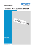
Headquarter & Production WIWA Wilhelm Wagner GmbH & Co. KG Gewerbestraße 1 – 3 • 35633 Lahnau, Germany Tel. +49-6441-609-0 • Fax +49-6441-609-50 E-mail: [email protected] • Internet: www.wiwa.de WIWA LP 3734A Cook Blvd. • Chesapeake, VA 23323, USA Tel. +1-757-436-2223 • Fax +1-757-436-2103 Tel.(Toll Free) +1-866-661-2139 • E-mail: [email protected] • Internet: www.wiwa.com WIWA Taicang Co., Ltd. Add.No. 87East Suzhou Rd. • Taicang city • Jiangsu province 215400 • P.R.China Tel.: 86-512-5354-8858 • Fax.: 86-512-5354-8859 E-mail: [email protected] User's Handbook FLUID HEATER 3500R / 230V 3500R / 400V 3500R / 440V, 3-phase High-Pressure (HP) Fluid Heater 3500R / 440V, 1-phase 0649442 — 0648376 0657724 — Low Pressure (LP) Fluid Heater — 0653488 (o. Reg.) 0648377 0654017 Manufacturing-No.: Translation of the original operation manual Fluid Heater MDFE_oA • en • 01.10 • cf Content 1 Content 1.1 Preface 1.2 english This User’s Handbook must always be available to operating staff. The operating authority of the equipment must ensure that a User`s Handbook is available to the operator in a language which he understands. Dear customer! Thank you for your decision to purchase ment. equip- In the User’s Handbook, you can find all information required for the proper handling of your Fluid Heater. However, for safe operation, there are further essential details which you should adhere to: Please read and observe the guidlines valid for your country. In Germany, the „Richtlinien für Flüssigkeitsstrahler“ (Guidelines for Fluid Sprayers) published by: Hauptverband der Gewerblichen Berufsgenossenschaften (Industrial Employer‘s Liability Insurance Association), are valid. Manufacturer’s notes and operating guidelines for coating and pumping materials should be observed at all times. As the Fluid Heater can only be used in connection with spray equipment, the operating manuals for the spray equipment and any accessories used must be observed and followed. No method of operation should be exercised which impairs the safety of products and the operating personnel. We wish you much success and excellent working results when appliying your Fluid Heater. WIWA Wilhelm Wagner GmbH & Co. KG Read before starting! Fluid Heaters are designed for use in either high-pressure (HP) or low-pressure (LP) applications, depending upon the model. Improper use, especially in high-pressure applications, can cause life-threatening injury. ➤➤ Always observe the instructions and regulations given in the User's Handbook! It is important to check prior to each use: ➤➤ Proper grounding (pump and object to be sprayed). ➤➤ All connections and accessories for tightness/leaks. ➤➤ Observe the maximum allowable operating pressure for the fluid heaters, the spray equipment and any accessories. Before performing repairs on the unit, and upon each work interruption, it is important to: ➤➤ Adjust the fluid heater temperature to the minimum setting (turn temperature setting knob to position "I" or adjust at control panel). ➤➤ Disconnect the heater from the power source. ➤➤ Release pressure from the entire system Cleaning of the equipment is required: ➤➤ Before initial operation ➤➤ Before longer interruptions in work ➤➤ Upon each change of material ➤➤ Immediately after use of 2K-Materials, but only after cooldown (observe the pot-life of the material) Pay attention to safety! The accident prevention regulations „Working with Coating Materials“ (BGV D25) and the regulations for liquid sprayers (ZH1/406) from the Association of Industrial Liability must be observed. Liquid sprayers must be inspected for safe working condition at least once every 12 months by a qualified technician. The results of the inspection are to be recorded in writing. Paint and solvent residues must be disposed of in accordance with regulations. This applies to environmentally friendly water-based paints also! In case of injury, proceed immediately to the nearest doctor or medical facility. If paint or solvent has penetrated the skin, the doctor must be informed about the type of material and solvent which was used. Always have the material data sheet available with the manufacturer‘s address and telephone number. 2 Translation of the original operation manual Fluid Heater MDFE_oA • en • 01.10 Rev 1211• cf • Content Table of contents 1 1.1 1.2 1.3 1.4 Contents2 Preface2 Read before starting! 2 Table of contents3 Description of the fluid heater 4 2 2.1 2.2 2.3 2.4 2.5 2.6 2.7 2.8 2.9 2.10 2.11 Safety6 Explanation of symbols 6 Warning labels on the fluid heater 6 Dangers arising from the equipment 7 Application of the machine 7 Machine surroundings 7 Sources of danger and safety warnings 8 Operating staff 9 Installation site 10 Behaviour in case of emergency 10 Protective devices 11 Handling of the machine and auxiliary materials 11 3 3.1 3.2 Machine description Equipment versions Designation of components 4 4.1 4.2 4.3 Start-up15 Erection and preparation 15 First cleaning 16 Pressure testing 16 5 5.1 5.2 5.3 Operation / Shutting down Equipment preparation Change of material Shutting down 6 Checks19 Copyright 7 Malfunctions and trouble-shooting © 2008 WIWA 8 8.1 8.2 8.3 Appendix21 Technical specifications 21 Certificate of training and operation 22 Declaration of conformity 22 Copyright ownership for this user manual remains with WIWA WILHELM WAGNER GmbH & Co. KG Gewerbestraße 1-3 • 35633 Lahnau, Germany Phone: +49 (0)6441 609-0 • Fax: +49 (0)6441 609-50 12 12 14 17 17 18 18 20 This operating manual is solely intended for personnel involved in preparation, operation and servicing. It is prohibited to pass on this operating manual for reproduction, utilisation or communication of its contents, unless this has been explicitly permitted. Infringements incur an obligation to pay damage compensation. All rights reserved in the event of registration of the patented design, industrial design or registered design. This operating manual only applies in conjunction with the machine card that was given to you with the user manual for your equipment. Please check that the type plate data is identical with the information on the machine card. Please notify us immediately if there are discrepancies, if the user manual has been incorrectly compiled or if the type plate is missing. Translation of the original operation manual Fluid Heater3 MDFE_oA • en • 01.10 Rev 1211• cf • english 1.3 Safety 2 Safety 2.2 2.1 Explanation of symbols The warning labels and symbols on the Fluid Heater indicate possible sources of danger and must be observed accordingly. The signs and symbols used in this manual have the following meaning: english NOTE This marks a section of text which is especially relevant to safety. Special attention should be paid to this section and the contents strictly observed. SMOKING PROHIBITED This marks a situation in which a fire hazard arises through the use of flammable or explodable solid, fluid or gaseous materials. WARNING This marks a situation which could be dangerous. If not observed,death or very serious injuries could result. DANGER OF EXPLOSION This marks a situation, where there is danger of explosion. Observation of this information is absolutely essential. ELECTRICAL VOLTAGE This marks a situation, where there is a danger of explosion through an electostatic charge. Observation of this information is absolutely essential. HOT SURFACES This marks a situation where there is danger of burns caused by hot surfaces. Hot surfaces should not be touched unless wearing protective gloves. WEAR PROTECTIVE GLOVES Wear protective gloves with lower arm protection to avoid burn injuries. The warnings must be adhered to. HEALTH DANGER This marks materials which are hazardous to your health. Observation of this information is absolutely essential. FIRST AID In case of injuries or accidents, these instructions should be absolutely adhered to. Warning labels on the fluid heater Warning labels and symbols may not be removed from the equipment. Damaged or illegible warning labels and symbols must be immediately replaced. The following labels are found on the Heater: Warning label "Attention! Important Warning!" Achtung! Wichtige Hinweise! yy Nur im kalten und spannungsfreien Zustand spülen! yy Flammpunkt des Spritzmaterials beachten! Attention! Important Warning! yy Flush only in cold and unplugged state! yy Watch the flash point of the spraying materials! Picture 2.1 Warning label "Danger! Disconnect power supply before opening!" Picture 2.2 Warning label "Hot surface" Picture 2.3 Nameplate Please insure that the data on the type plate is in accordance with the information in the user‘s handbook. If there are discrepancies, or if the nameplate is missing, please notify us immediately. Picture 2.4 4 Fluid Translation of the original operation manual Fluid Heater MDFE_oA • en • 01.10 Rev 1211• cf • Safety Dangers arising from the equipment This machine was designed and built in accordance with all safety aspects. It corresponds with the present standards of technical regulations and current rules for accident prevention. This equipment left the factory in perfect condition and guarantees the highest level of safety. However, the following dangers exist if operated incorrectly or used inappropriately: ➤➤ to life and limb of operator or third personsor ➤➤ for the machine and other property belonging to owner of machine ➤➤ for the efficient working of the machine All personnel involved in the starting, operation and maintenance of the machine must read the following notes carefully and observe them. It is a matter of their safety! We recommend that the machine operation management have this confirmed in writing. Additionally, please pay attention to the following: Please, read and observe the guidlines valid for your country. In Germany the „Richtlinien für Flüssigkeitsstrahler“ (Guidelines for liquid sprayers), Published by: Hauptverband der Gewerblichen Berufsgenossenschaften, are valid. We recommend adding a copy of all guidelines and accident prevention regulations into the user‘s manual. Manufacturer’s notes and operating guidelines for coating material and pumping material should be observed at all times. In principle, no method of working should be exercised which impairs the safety of products or the operating personnel. 2.4 Machine surroundings Rebuilds and changes For safety reasons, it is not allowed to carry out rebuilds or changes without authorization. Protective equipment may not be dismounted, changed or neglected. If using components which are not produced or delivered by , warranty coverage is negated as well as liability. The machine may only be operated within the prescribed limits and machine parameters. Danger caused by attachments and spare parts If you use original attachments and original spare parts from , the compatability with our equipment is guaranteed. It is, however, essential that the safety regulations of the attachments and spare parts are observed. You can find these safety regulations in the User’s Handbook located with the spare parts lists. If you use attachments and spare parts from another source, cannot guarantee the safety of the entire system. In this case, our guarantee does not cover any damage or injury caused by such attachments and spare parts. Emissions It is possible for solvent vapours to occur, depending on the materials used. Therefore, please ensure the workplace is sufficiently ventilated in order to avoid damage to health and property. Always observe the processing information given by the material manufacturer. The operation of the fluid heater is noiseless. 2.5 Sources of danger and safety warnings The Fluid Heater may only be used, according to version (HP or LP), in high- or low-pressure applications with the corresponding spray equipment and accessories. The User‘s Handbook for the spray equipment and accessories must be read and followed. Inappropriate use can lead to severe injury. It is especially important to note that when used as a component in Air-Combi, Airless or Airless-2K spray units, that this is high-pressure equipment which can cause life-threatening injury. Translation of the original operation manual Fluid Heater5 MDFE_oA • en • 01.10 Rev 1211• cf • english 2.3 Safety Please observe and obey the following: english ➤➤ Power supply cables which are not Ex-Proof may only be used outside of rooms where explosion-proofing is required. ➤➤ Use in an area where solvent vapours exist can cause the power cable to become porous or cracked. Therefore, the power cable must be inspected visually for damage before each operation. Never make repairs to the power cable. It must be replaced completely by a qualified technician. ➤➤ Before connecting the Fluid Heater to the electrical supply, check to ensure that the point of hook-up is functioning correctly and no faults are present. ➤➤ In case of power failure, disconnect the power supply to prevent the Fluid Heater from switching on independently. ➤➤ Residual material left in the Fluid Heater can harden and lead to damage of the unit. The heater must be completely flushed with an appropriate solvent within the potlife given by the material manufacturer, but only when the heater is cold. Please observe that the potlife of plural component materials is shortend considerably by heating. ➤➤ DANGER OF EXPLOSION! Flush and clean with solvent only when the heater is cold and disconnected from the power source. Never heat solvent in the Fluid Heater! ➤➤ DANGER OF EXPLOSION! Never spray solvent or material containing solvent into narrow-necked cans or drums with bungholes! ➤➤ DANGER OF EXPLOSION! The unit may not be opened when located in and exposed to explosive environments ➤➤ DANGER OF EXPLOSION! Always observe the flashpoint of matierals to be heated. When setting the desired temperature, never exceed the flashpoint temperature of the material that has been stated by the mateirals manufacturer. ➤➤ For each material sprayed, the corresponding data sheets must be available. The information surrounding the viscosity, working temperature (flashpoint) and the mixing ratio stated by the manufacturer must be observed and followed closely. ➤➤ BURN DANGER! The temperature on the outside of the Fluid Heater can more than 80°C (176°F), depending on the temperature setting. Therefore, it is important to always wear protective gloves! ➤➤ Always observe that the fluid hoses do not come into contact with the hot surfaces of the Fluid Heater. ➤➤ Depending on the temperature selected, the spray gun can become very hot. Always wear the appropriate protective gloves and clothing. ➤➤ When starting the unit and after any repairs, maintenance or cleaning have been performed, make an optical check 6 ➤➤ ➤➤ ➤➤ ➤➤ ➤➤ ➤➤ of the equipment for any signs of leaks or other defects. Never try to stop a leak at a fitting or high pressure hose using your hand or by wrapping with a rag, etc. When a leak is detected, the entire system (spray pump, gun, hose, filter, etc.) must be pressure released immediately, and the defective parts must be replaced. Follow the instructions in the User's Handbook for the spray equipment and accessories. The entire system (spray pump, heater, accessories) must be shut down and pressure released before any work (maintenance/repair/cleaning) is performed! Read and follow the operating manual for the spray equipment and accessories. ➤➤ Switch the Fluid Heater to position „I“ ➤➤ Disconnect the power supply. ➤➤ Release the pressure in the heat exchanger of the Fluid Heater Upon stoppage or hardening of material in the equipment, residual pressure can exist in spite of pressure release. Take this into consideration when repairing the Fluid Heater. Wear protective gloves and glasses, and loosen the hose connections very carefully. We recommend that you cover the connections with a rag when loosening to prevent the spraying of material. Due to electro static charges, only conductive material hoses should be used. All original material hoses are conductive and compatible with our equipment. The maximum admissible working pressure on the hoses must correspond to the maximum operating pressure of each airless machine. In closed or pressurised systems where aluminium or galvanised parts come into contact with the solvent, dangerous chemical reactions can occur if 1.1.1-Trichlorethylene, Methylene Chloride or other solvents containing halogenated chlorinated hydrocarbons (CFCs) are used. If you wish to work with the above solvents or with lacquers and paints which contain them, we recommend you contact either customer services or directly. All fluid-wetted parts of the Fluid Heater are constructed of rust- and acid-resistant material. For processing of the above mentioned materials, use only spray equipment and accessories in the rust- and acid-resistant version. The maximum operating pressure given by must be observed for each component (pump, heater, hoses, spray gun, safety valve, etc.). The lowest value is to be taken for the complete system. Example: Pump 420 bar / 6090 psi Hose 600 bar / 8700 psi Spray gun 500 bar / 7250 psi Tip guard350 bar / 5075 psi The maximum permissible operating pressure for this complete system would be: 350 bar / 5075 psi. Smoking, open flames or any other possible ignition sources are not allowed anywhere near the area of operation. Translation of the original operation manual Fluid Heater MDFE_oA • en • 01.10 Rev 1211• cf • Safety Operating staff Authorised Operators People under the age of 16 should not operate this equipment. The management in charge of the operation of the machine must make the user’s handbook available to the operator and must make sure that he has read and understood it. Only then may the system be put into operation. We recommend the manager has this confirmed in writing. The operator of the machine is obliged to report any changes in the machine which might affect its safety to the manager, as he must ensure that the machine is functional. The responsibilities for the different activities on the system must be laid down clearly and adhered to. No unclear responsibilities may remain as these could endanger the safety of the users. The operator must make sure that only authorised persons work on the machine. He is responsible to third parties in the working vicinity of the system. The operator of the equipment is obliged to repeat instructions about dangers and safety measures at regular intervals (at least once a year, for young persons twice a year). Personal protective equipment We call to your attention that the valid guidelines and requirements in accordance with work surroundings (mining, closed areas etc.) must be absolutely adhered to. Please, wear the prescribed protective clothing at all times, as solvent vapours and solvent splashes cannot be completely avoided. To prevent burn injuries, never touch the Fluid Heater unless wearing protective gloves. 2.7 Installation site Safety measures at installation site ➤➤ Mount the Fluid Heater securely on the spray unit, a wall bracket or the frame with carrying handle. The system must have a fixed position and sufficient space to ensure safe operating. The passage to the safety fittings must not be blocked. ➤➤ For versions without cable and cable connection, the owner / operator of the equipment has to mount cable connectors are used. This work may only be performed by a qualified electrician. Observe the Ex-Proof zoning of the workplace. ➤➤ Before connecting the Fluid Heater to the electrical supply, check to ensure that the point of hook-up is functioning correctly and no faults are present. ➤➤ The owner / operator of this equipment is required to ensure that proper protection against lightning strikes is available. ➤➤ Keep the working area, especially all gangways and standing areas, clean. Remove spilled paint or solvent immediately. ➤➤ Pay attention that no moisture (ex: through rain, highpressure cleaning, etc.) gets into the Fluid Heater. The Fluid Heater must never be immersed in a container of liquid (ex: solvent). ➤➤ Ensure there is sufficient ventilation at the workplace to prevent damage to health and property. Observe the manufacturer’s processing instructions at all times. ➤➤ Read and follow the instructions in the User's Handbook for the spray equipment and accessories. Comply strictly with the current rules for accident prevention. Never use solvent or other materials which present a health hazard for cleaning skin. Only suitable skin protective, skin cleansing and skin care materials may be used. Translation of the original operation manual Fluid Heater7 MDFE_oA • en • 01.10 Rev 1211• cf • english 2.6 Safety 2.8 Behaviour in case of emergency english Leaks If any leaks occur from the Fluid Heater, the electrical power supply is to be disconnected immediately. ➤➤ The entire system, including the Fluid Heater, must then immediately be depressuried. Close the air tap for the inbound air supplying the equipment. ➤➤ Depressurize the system by opening the spray gun or the pressure drain for the pump (i.e. at the high-pressure filter). When doing this, the instructions found in the User‘s Handbook for the pump and accessories are to be adhered to strictly. ➤➤ Defective parts must be replaced immediately. Injury ➤➤ Should an injury occur through contact with liquid spray, we recommend a doctor be called immediately. ➤➤ Inform the doctor about the type of material (paint) and the solvent (thinner) used. Have the product data sheet at hand (address and telephone number of supplier or manufacturer, name of material and material number) ➤➤ Memorize the local emergency phone numbers. ➤➤ In any case, become familiar with the first-aid measures. Fire ➤➤ Read the instructions for fire alarm and escape routes put up in your factory. ➤➤ Memorize the local emergency phone numbers. ➤➤ Take care that sufficient information notes/labels for fire prevention are provided. ➤➤ Do not apply any other extinguishing agents than those which are prescribed by the manufacturer of the materials. 2.9 Protective devices If a protective device is not fully operative, or another defect is detected on the machine, interrupt the compressed air supply to the machine and disconnect the heater immediately from the power source. Follow the instructions in the User‘s Handbook for the spray equipment. The machine may be restarted only if perfect operation is restored. All protective devices must be inspected for proper function: ➤➤ Before each commissioning of the machine! ➤➤ Before beginning work with the unit! ➤➤ After each alignment! ➤➤ After cleaning and servicing! ➤➤ After maintenance and repair! Checklist for inspection of the protective devices on the pressure-released machine: Inspect ground cable for damage. Inspect the ground cable connection to the unit and the ground circuit. All Fluid Heaters are supplied with the following safety devices: Temperature Limiter The temperature limiter turns off the fluid heater when it exceeds the max. allowed temperature. To reset, press the button (pict. 2.5). Picture 2.5 The fluid heater is operating when the control lamp is illuminated or when shown on the control panel. Ground Cable A separate grounding of the Fluid Heater is required when no electrically-conductive connection to the spray unit exists. Connect the ground cable on the provided grounding screw (Picture 2.10.2). Order-Number for the Ground Cable: 0474487 Make sure that the unit is grounded either separately or together with the equipment it is mounted to (maximum resistance 106 Ω ground / potential equalization). 8 Translation of the original operation manual Fluid Heater MDFE_oA • en • 01.10 Rev 1211• cf • Safety The grounding screw is located near the power cable connection and is marked with . english Picture 2.6 2.10 Handling of the machine and auxiliary materials Alignment, servicing, maintenance and repair of the machine Alignment when changing production, as well as servicing and cleaning, may be carried out by trained operating personnel only. Maintenance and repair may be carried out by trained, qualified personnel only. Before starting work, the compressed air supply to the machine must be shut-off and the Fluid Heater disconnected from the power source. Residual pressure must be released through the spray gun or the drain on the High Pressure Filter. Read and follow the instructions in the User‘s Handbook for the spray equipment. After finishing work, the equipment and all protective devices should be inspected for proper function. Read and follow the instructions in the User‘s Handbook for the spray equipment and accessories. Handling of auxiliary materials When handling auxillary materials such as paint, solvents, oils, grease and other chemical substances, comply with the safety and dosing instructions of the manufacturer and the generally applicable regulations. Left over solvents, oils, grease and other chemical substances must be collected according to the legal regulations for recycling and waste disposal. The local official laws for the protection of waste water must be observed. Translation of the original operation manual Fluid Heater9 MDFE_oA • en • 01.10 Rev 1211• cf • Machine description 3 Machine description 3.1 Application of the machine english The Fluid Heater can be used, according to version (HP or LP), in high- or low-pressure applications for heating the applied materials and/or the compressed air supply. The following types of coating materials may be heated: ➤➤ Paint and lacquers ➤➤ Protective coatings (oil and grease) ➤➤ Stripping agents ➤➤ Insulation and fire-protection coatings ➤➤ Tar-epoxy and bituminous paints ➤➤ Polyurethane ➤➤ Water The Fluid Heater (Picture 1.2.1) consists of two main parts: ➤➤ Housing with electrical switch and heating elements. ➤➤ Heat exchanger with material inlet and outlet connections. Housing Picture 3.2 The heater may not be used in areas with risk of explosion! Before equipment is used for other purposes or with other materials, and, therefore, not according to the regulations, permission should be obtained from the manufacturer, as the guarantee is otherwise invalid. The observation of technical documentation and the compliance with specified operational, maintenance and starting guidelines are manditory in accordance with the valid regulations. Models 3500 HP Max. operating pressure: 450 bar / 6525 psi The High-Pressure Fluid Heater is especially suitable for use with Airless spraying systems, Airless plural component units und Air Combi systems. The advantages of the hot-spray process include higher coating thickness, shorter drying times and top-quality finishes. Heat exchanger Coating materials which are normally difficult or impossible to process due to their consistency become easily sprayable when warmed up using a Fluid Heater. Picture 3.1 Material flows through the heat exchanger and is warmed by the heat produced by electrical heating elements in the the housing. The lower part of the housing is conical. The heat exchanger has a matching conical form. Should a blockage occur in the heat exchanger, it can be removed from the housing by using the separating screw and then exchanged. The desired temperature can be steplessly adjusted (max. temperature 85°C) at the temperature setting knob on the fluid heater (pict. 3.2) or, for fluid heaters without temperature setting knob, at the control panel. With the addition of a mounting kit, the fluid heater can simultaneously be used for heating of the compressed air supply: a) as pre-heater for a air motor, to prevent icing caused by low outside temperatures and high humidity. b) for the heating of the atomizing air for Air-Combi systems. Through additional heating of the atomizing air, the quality of the finish is improved further and the drying time is shortened. Model 3500 LP Max. operating pressure: 200 bar / 2900 psi The Low-Pressure Fluid Heater is suitable for heating materials to be applied in low-pressure processes. Futhermore, the Low-Pressure Fluid Heater can be used for the supply of heated air to the air motor (deicing) or for preheating materials being fed to plural component spraying systems. 10 Translation of the original operation manual Fluid Heater MDFE_oA • en • 01.10 Rev 1211• cf • Machine description 3.2 Equipment versions Cart-mounted Airless Pump Cart-mounted Fluid Heater Spray Gun By adding a Fluid Heater, shorter curing times, higher film builds and top quality finishes can be achieved. In addition, heating influences viscosity. High-viscosity materials that would be difficult to spray under normal circumstances can now be handeled more easily. The required mounting kits are available for all Airless and Air-Combi units. Picture 3.3 Portable Fluid Heater (Picture 3.4) Cart-mounted Airless Pump Spray Gun Portable Fluid Heater This version is used additionally when high temperatures are required at the spray gun/tip. It is also applicable as an additional heating element when working with long spray hoses, to avoid line heat loss.. The following kit is required: Portable Frame for Fluid Heaters, Order No. 0632538, as well as a Fluid Heater. Picture 3.4 Airless pump with frame-mounted Fluid Heater and additional portable Fluid Heater. Translation of the original operation manual Fluid Heater11 MDFE_oA • en • 01.10 Rev 1211• cf • english Converting an Airless or Air Combi pump to an Airless or Air Combi Hot Spray version (Picture 3.3) Machine description Heating of air motors (de-icing system) by using a Fluid Heater (Picture 3.5) Air Maintenance Unit Connection Air Motor Upper Housing Air Motor Upper Housing english When operating with adverse ambient temperatures and high humidity, a Fluid Heater can be used to provide the air motor with heated air to avoid icing (de-icing system). A portion of the inbound air is tapped from the main line and routed through the Fluid Heater and then back to the air motor. This pre-heated air is then patched into the air/drain channels in the air motor to reduce the possibility of icing. The following kit is required: Air Heating Kit for Fluid Heater, Order No. 0632629 Picture 3.5 Atomization Air Heating for Air-Combi Hot Spray Units (Picture 3.6) Cart-mounted Air Combi unit Spray Gun Designed for reaching an optimal spray pattern, improved paint dispersion and shorter curing times. To avoid pre-heated material from cooling when coming in contact with the atomizing air, the Fluid Heater can also be used to heat the air before it goes into the spray gun. A portion of the inbound air is tapped from the main line and routed through the Fluid Heater and then out to the gun. To avoid line heat loss, the air and material hoses should be bound together and insulated. Picture 3.6 12 Translation of the original operation manual Fluid Heater MDFE_oA • en • 01.10 Rev 1211• cf • Machine description Designation of components Mounting screw for the heat exchanger (M 10) Torque: 13 Nm / 9.6 ft.lb. For use with air motor de-icing, these holes must be pluged Use the screws (M 10) included in the assembly kit „Air Motor De-Icing“ Separating screw for removing the heat exchanger from the housing (M 12) (for air motor de-icing and additional brass seal must be mounted) Inbound air (G 1/4“) (only for de-icing) Mounting screw for the heat exchanger (M 10) Torque: 13 Nm / 9.6 ft.lb. Main housing with all electrical switches and heating elements Outbound air (G 1/8“) (only for de-icing) Connection for inbound material (HP: 3/8“ NPSM / LP: 3/4“) Heat exchanger Connection for outbound material (HP: 3/8“ NPSM / LP: 3/4“) Fluid heater with temperature setting knob Fluid heater without temperature setting knob (for remote control) Button to reset the temperature limiter Control lamp Temperature setting knob Temperature sensor Power supply Translation of the original operation manual Fluid Heater13 MDFE_oA • en • 01.10 Rev 1211• cf • english 3.3 Start-up Erection and preparation 1. Obseve the User‘s Handbooks for the pump and accessories english Fluid Heaters can only be used in conjunction with spraying equipment. Therefore, all instructions covering unit preparation, commissioning, operation and shutting-down must be compared to those covering the spraying equipment itself for compatability. ➤➤ Read and observe the instructions found in the user‘s handbooks for the spraying equipment, the fluid heater and any additional spray accessories. ➤➤ Pay special attention to chapters covering safety in the user's handbooks. ➤➤ The risk of solvent fumes and/or splashes can never be fully eliminated. Always wear proper protective clothing to avoid injury. 2.a) Connect the power supply (Fluid heater with temperature setting knob) ➤➤ The heater is equipped with a permanent power connection cable without plug. For versions without cable and cable connection, mount cable connectors. ➤➤ Before connecting the Fluid Heater to the electrical supply, check to ensure that the point of hook-up is functioning correctly and no faults are present. This should only be done by trained electrical personnel. Note: this equipment is not suitable for use in Ex-proof zones. 2.b) Connect power supply and temperature sensor (fluid heater without temperature setting knob) ➤➤ For fluid heaters with connection for remote control: Unsrcew the cover of the heater and mount the connection cable and temperature sensor (PT100 3-wire sensor) on the bus bar according to the wiring diagram. This should only be done by trained electrical personnel. Note: this equipment is not suitable for use in Ex-proof zones. 14 ➤➤ Securely mount the Fluid Heater to your spray equipment, on a wall-mount oder on a portable frame (refer to Chap. 3.1). 4. Ground the unit ➤➤ To avoid electrostatic charging, the Fluid Heater must be grounded to a conductive object by way of the grounding cable. ➤➤ The object to be coated must be grounded as well. 5. Mount the fluid hoses ➤➤ Remove the yellow caps from the heat exchanger's material inlet and outlet. ➤➤ De-Icing (Picture 4.1.1, Pos. 1 + 2 ): Use a male adaptor to mount the fluid hoses to the Fluid Heater. The connections must be sealed using either teflon tape or medium-strength thread sealant (i.e. Loctite®). ➤➤ Approximately 80 Nm (59 ft.lb.) torque must be applied. ➤➤ The part no. for the male adaptor can be found in Chapter 8.1. ➤➤ Further part numbers for addtional connections can be obtained by contacting Customer Service. 4.1 3. Mount the Fluid Heater Start-up 4 1 Inbound Material (IN) 2 Outbound Material (OUT) 3 Inbound Air 4 Outbound Air Picture 4.1 6. Mount De-Icing Assembly (for 300 and 333 air motors) and the mounting kit (for 200 and 230 air motors) ➤➤ De-Icing (Picture: 4.1, Pos. 3 + 4). Mount the kit to the Fluid Heater. ➤➤ For the inbound air connection, an elbow fitting is mounted to the bottom of the unit. ➤➤ Furthermore, a brass washer must be fitted under the separating screw. It must be removed again before using the screw to separate the heater housings. ➤➤ Screw an adaptor into the outbound air connection on the Fluid Heater. Connect a compressed air line between the upper housing of the air motor and the Translation of the original operation manual Fluid Heater MDFE_oA • en • 01.10 Rev 1211• cf • Start-up 4.2 First cleaning This Fluid Heater was function tested at factory using a test-medium. To ensure that no test medium is left in the pump, the entire system should first be flushed using the solvent recommended by the manufacturer of the coating to be used. ➤➤ Disconnect the heater from the power source. ➤➤ Now complete all steps covering the initial flushing found in the spraying equipment's User's Handbook. mind. 1 minute max. 5 minutes approx. 8-25l (2-6.5 gal.) 4.3 For best results, we recommend flushing the system for approximately one minute. To avoid any danger of explosion, do not allow the solvent to circulate for more than 5 minutes and ensure that the amount of available solvent corresponds to the size of the pump used. Depending on the pump, at least 8 to 25 liters (2 to 6.5 gallons) of solvent are necessary. Pressure testing The maximum operating pressure of the Fluid Heater must be equal to or greater than the max. operating pressure of the spraying equipment and any accessories. The lowest value is to be taken for the complete system. ➤➤ Disconnect the heater from the power source. ➤➤ Ensure that the Fluid Heater and been connected according to the instructions found in Chapter 3.1 and that all fittings are tightened properly. ➤➤ Now complete all steps found in the spray equipment's User's Handbook covering pressure testing of the system. Translation of the original operation manual Fluid Heater15 MDFE_oA • en • 01.10 Rev 1211• cf • english Fluid Heater (refer to Chap. 3.1 + 3.2). ➤➤ The part no. for the de-icing kit is located in Chapter 8.1. ➤➤ Further part numbers for addtional connections can be obtained by contacting Customer Service. Operation 5 Operation 5.1 Equipment preparation 5. Setting the temperature ➤➤ Set the desired temperature on the temperature knob (Picture 5.1.1). 1. Safety english ➤➤ Always remember that the Fluid Heater may only be flushed when cold an disconnected from the electrical power supply. ➤➤ Always observe the working temperature given by the manufacturer of the coating to be heated. ➤➤ Check to ensure that accessories (i.e.temperature gauges, back pressure valves) are connected correctly. ➤➤ Check to ensure that the pressure ratings of all system components and accessorires correspond to the maximum operating pressure of the Fluid Heater. ➤➤ Check for the proper ground of: ➤➤ spray pump ➤➤ Fluid Heater ➤➤ accessories ➤➤ object to be coated ➤➤ Observe all instructions found in the User‘s Handbook for the spray pump and all accessories. The control lamp remains lit while the Fluid Heater is heating. Once the set temperature is reached, the lamp goes out. If the heater begins heating again, the lamp will turn on again. If the ambient temperature is under 10°C (50°F), the reset button (Picture 5.1.1) must be pressed until the control lamp turns on. Reset Button Temperature setting knob Picture 5.2 If the maximum allowable temperature is surpassed, a temperature limiter will turn off the Fluid Heater. To turn the Fluid Heater back on, press the reset button (Picture 5.1.1) until the control lamp goes on again. 2. Prepare paint spray equipment Follow the instructions for preparing the system for spraying found in the User’s Handbook for the equipment. 3. Flush Due to the possibility that solvent or solvent fumes can still be found within the Fluid Heater and/or spray system, the coating must first be sprayed cold for approx. one to two minutes back into the material feed container. 4. Power supply connection Connect the Fluid Heater power supply cable to a corresponding electrical connection. The Fluid Heater must be rated for the available power supply (voltage, amperage, wattage). 16 6. Operation The spray system and Fluid Heater are now ready for operation. ➤➤ You can now commence with coating the desired object. ➤➤ Pay close attention to the instructions found in the User‘s Handbook for the spraying equipment. ➤➤ N ever place hands or fingers in or near the spray jet. ➤➤ If using a Hot Spray system without circulation, cold material is still located in the hoses. It is recommendable to pump the material back into its container until heated material exits the spray gun. ➤➤ When using two-component materials, the potlife must be observed. Translation of the original operation manual Fluid Heater MDFE_oA • en • 01.10 Rev 1211• cf • Operation Change of material The entire system has to be flushed thoroughly to avoid any possible chemical reaction with the new coatings material. 1. Shutting down ➤➤ Follow all the instructions found in Chapter 5.3 „Shutting down“. 5.3 Shutting down 1. Turn off the Fluid Heater ➤➤ Turn off the Fluid Heater 10 minutes before work is completed. ➤➤ To do this, turn the temperature knob to the position „I“ (Picture 5.3.1). ➤➤ This will enable the operater to use the residual heat up until the end of work while shortening the cooling time until the unit can be flushed. 2. Shutting down the equipment ➤➤ After disconnecting the heater from the electrical power supply, perform all steps covering changing materials and/or shutting down as found in the User‘s Handbook for the spray pump/system. Temperature setting knob Picture 5.3 10 minutes before the end of work 3. Flush ➤➤ Flush the complete system: ➤➤ when the unit is cold ➤➤ disconnected from the electrical power supply approx. 2 minutes Operation Use the solvent that is recommended by the coatings manufacturer. Follow the instructions found in the pump‘s/ system‘s User‘s Handbook covering changing materials and/or starting up the unit. 2. Disconnect from electrical power supply ➤➤ Disconnect the heater from the electrical power supply. 3. Flush ➤➤ Avoid damage to the unit and the entire system by thoroughly flushing after every shutdown. ➤➤ Follow additionally the instructions located in the corresponding User‘s Handbook for the spray equipment being used. 4. Restarting the unit ➤➤ Follow the instructions found in the User‘s Handbook for the spraying equipment being used. ➤➤ Complete the instructions found in Chapter 5.1, Step 4-6. Translation of the original operation manual Fluid Heater17 MDFE_oA • en • 01.10 Rev 1211• cf • english 5.2 Checks 6 Checks According to the rules for the prevention of accidents „Working with liquid jet systems“ BGV D15 the equipment must be checked and overhauled at regular intervals by a specialist ( Service). english The equipment must be checked: ➤➤ before the first start-up, ➤➤ after changes and repairs of equipment parts having an effect on safety, ➤➤ after an interruption of operation of more than 6 months, ➤➤ however at least every 12 months. For equipment, which has been taken out of operation, the check can be postponed up to the next start-up. The results of the checks must be recorded in writing and kept until the next check. The checking certificate or a copy of it must be available at the place where the equipment is used. Maintenance instructions for the spray equipment and accessories can be found in the corresponding User‘s Handbook. 18 Translation of the original operation manual Fluid Heater MDFE_oA • en • 01.10 Rev 1211• cf • Malfunctions and trouble-shooting Malfunctions and trouble-shooting Fault Possible Cause Solution Material in the heater does not beco- ➤➤ No electricity ➤➤ A: Check that electricity is available me warm at all ➤➤ The temperature limiter has shut ➤➤ B: Check the power connection off the fluid heater and power supply cable and replace if necessary. The above solutions (Point A and B) may only be performed by qualified electrical personnel ➤➤ C: Press the reset button (picture 5.1.1, page 15) until the control lamp lights. Material heats but does not reach the ➤➤ desired temperature ➤➤ ➤➤ ➤➤ Heating cartridges are defect ➤➤ Contact Customer Service Temperature limiter is defect ➤➤ Contact Customer Service Temperature is set incorrectly ➤➤ Reset the temperature using the The amount of material passing temperature knob throught the heater is too large ➤➤ Lower material flow (smaller tip size) ➤➤ Add a second Fluid Heater in series to the system Male adaptors or fluid hoses are ➤➤ Male adaptors and/or fluid hoses ➤➤ Re-tighten the male adaptors and/ leaking are not tightened correctly or daor fluid hoses or replace as necesmaged sary Material does not flow ➤➤ Heat exchanger is clogged ➤➤ If the material in the heater is not completely cured, it may be possible to remove it by flushing under high pressure: HP max. 450 bar (6525 psi) / LP max. 200 bar (2900 psi). Due to the danger of explosion, the Fluid Heater may only be flushed when completely cold. Thoroughly flush the heat exchanger or replace if necessary. If the material is fully cured (especially with two-component materials), the heat exchanger must be replaced. The heat exchanger may only be replaced when the Fluid Heater is cold and disconnected from the electrical power supply. To remove, loosen the two mounting screws and screw in the separating screw (Chapter 3.2) until the heat exchanger has separated from main housing. Before mounting, the cone-shaped surface inside the heat exchanger must be coated completely with copper paste ( Order No. 0000233). Translation of the original operation manual Fluid Heater19 MDFE_oA • en • 01.10 Rev 1211• cf • english 7 Appendix 8 Appendix 8.1 Technical specifications High-Pressure (HP) 0649442 Order No. english Max. Voltage (± 10%) (± 10%) (V) Max. Amperage (Ampere) Max. Wattage (kW) Max. Temperature* (°C / °F) 230 V, 1 ph 0657724 440 V, 3 ph 16 A 5 A Weight (kg / lbs.) 0653488 0654017 440 V, 3 ph 400 V, 3 ph 440 V, 1 ph 5 A 5,5 A 8 A 3,5 kW 3,5 kW 3,5 kW 3,8 kW 3,5 kW 85 / 185 85 / 185 85 / 185 85 / 185 3 Dimensions (LxWxH) (mm / in.) 0648377 120 / 248 Max. Operating Pressure (bar/psi) Connection Threads 0648376 / Low-Pressure (LP) 450 / 6525 200 / 2900 /8 NPSM inner thread ¾" 17,6 / 38.8 18,5 / 40.8 405 x 220 x 180 / (approx. 16 x 9 x 7) *with 1.8 kW one liter of water can be heated to 25°C (77°F) in one minute. *with 2.0 kW one liter of water can be heated to 28°C (82°F) in one minute. *with 3.5 kW one liter of water can be heated to 50°C (122°F) in one minute. fluid hoses must be used. 8.2 Accessories Temperature Gauge (Picture 1.2.3) to read the temperature at the material outlet of the Fluid Heater. These hoses are then mounted to the outbound connection on the Fluid Heater and the inbound connection on the circulation valve (Picture 1.2.5). The circulation valve is to be mounted in the direction of material flow between the material pump and suction hose. Please note the arrow on the valve housing. Depending on the pump model, the circulation valve either comes standard (Picture 1.2.5) or optionally (Picture 1.2.6) with a pressure drain valve. Picture 1.2.3 Fluid Heater with HighPressure Filter and Temperature Gauge Temperature Indicator If using long spray hoses or if the exact material temperature at the tip has to be monitored, a thermometer is required that is both long and capable of handling the spray pressure at the tip. The thermomoter must be held into the spray jet with at least 5 cm (2 in.) distance from the spray tip. Never place hands or fingers into or near to the spray jet. The desired circulation speed can be set using the regulating knob (Picture 1.2.4, Pos.1). Flow Direction Picture 1.2.4 Circulation Valve (without pressure drain valve) Circulation Valve (Picture 1.2.4) - for circulation systems Circulating avoids heat loss of material in hoses or feed lines during pauses in spraying. If a circulation valve is used, a spray gun with two inbound 20 Translation of the original operation manual Fluid Heater MDFE_oA • en • 01.10 Rev 1211• cf • english Appendix Spray Gun Connection Circulation Valve (with pressure drain valve) Picture 1.2.5 Circulation Valve (without pressure drain valve) Picture 1.2.6 Accessories Order No‘s Portable frame for HP (incl. all mounting parts) 0632538(N) / 0639788(R) Portable frame for LP (incl. all mounting parts) 0633869 Wall-mount for HP and LP 0486442 Mounting kit for air heating on Air Motor D300 0632629 Mounting kit for air heating on Air Motor D200 0633889 Mounting kit for air heating on 2K System 0634649 Mounting kit for atomization air heating 9999999 Male adaptor for material inlet and outlet (HP hose) Male adaptor for material inlet and outlet (LP hose) Temperature gauge 0484970 (N , 3/ 8“ NPT) 0219096 (RS, 3/ 8“ NPT) 0212776 (R, 3/ 4“) 0620661 back pressure regulator (Version: RS, 100-235 bar / 1450-3407 psi) 0634706 Copper paste 0000233 Translation of the original operation manual Fluid Heater21 MDFE_oA • en • 01.10 Rev 1211• cf • Appendix 8.3 Certificate of training and operation This certificate corresponds to the EU guideline for working substances 85/655/EWG, Paragraph II, Article 7. The owner of the following machine has trained the operating personnel. …………………………………………………………………...........… (Make, Model, Year of Construction, Order Number) english The training was conducted by the following designated person: …………………………………………………………………...........… (Foreman or responsible Superior, Name, Department) The persons trained have read and understood the User‘s Handbook for the above mentioned machine, especially the Chapter „Safety“, and are certain that they can operate this machine safely. …………………………………………………………………...........… (Operating Personnel, Date, Name) …………………………………………………………………...........… (Personnel for Maintenance and Repair, Date, Name) …………………………………………………………………...........… (Personnel Electric/ Electronics, Date, Name) 8.4 EC-Declaration of conformity We, WIWA Wilhelm Wagner GmbH & Co. KG Gewerbestraße 1 – 3 D-35633 Lahnau hereby declare in sole responsibility that the product Fluid Heater, machine types: Fluid Heater 3500 to which this declaration relates complies with the following standards and documents, ➤➤ in accordance with the EC low voltage directive 2006/95/EG Documentary authority: Heidrun Wagner-Turczak Lahnau, 01.01.2010 Place, date 22 Heidrun Wagner-Turczak Managing Director Translation of the original operation manual Fluid Heater MDFE_oA • en • 01.10 Rev 1211• cf •