1
Medical–Biological
Research & Technologies
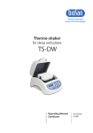
PST-100HL
Plate Shaker-Thermostat
Operating Manual
Certificate
for version
V.1AW
Contents
1.
Safety Precautions
2.
General Information
3.
Getting Started
4.
Operation
5.
Specifications
6.
Maintenance
7.
Warranty and Claims
8.
Declaration of Conformity
Page 2
1.
Safety precautions
The following symbols mean:
Caution!
Make sure you have fully read and understood the present
Manual before using the equipment. Please pay special
attention to sections marked by this symbol.
Caution!
Hot surface! Platform surface becomes very hot during use.
Always use protective cotton gloves to install or remove
microtest plates and to fix or release fixation holder when set
temperature is higher than 60ºC.
GENERAL SAFETY
·
Use only as specified in the Operating Manual provided.
·
The unit should be saved from shocks or falling.
·
The unit must be stored and transported in a horizontal position (see
package label).
·
After transportation or storage keep the unit under room temperature for 2-
3hrs before connecting it to the electric circuit.
·
Use only cleaning and decontamination methods recommended by the
manufacturer.
·
Do not make modifications to the design of the unit.
ELECTRICAL SAFETY
·
Connect only to the external power supply unit with voltage corresponding to
that on the serial number label.
·
Use only the external power supply unit provided with this product.
·
Ensure that the switch and external power supply unit are easily accessible
during use.
·
Do not plug the unit into an ungrounded power socket, and do not use an
ungrounded extension lead.
·
Disconnect the unit from electric circuit before moving.
·
Disconnect the external power supply unit from power socket to turn off the
unit.
·
If liquid penetrates into the unit, disconnect it from the external power supply
unit and have it checked by a repair and maintenance technician.
·
Do not operate the unit in premises where condensation can form. Operating
conditions of the unit are defined in the Specifications section.
Page 3
DURING OPERATION
·
Do not leave the operating unit unattended.
·
Do not impede the platform motion.
·
Do not operate the unit in environments with aggressive or explosive
chemical mixtures.
·
Do not operate the unit if it is faulty or has been installed incorrectly.
·
Do not use outside laboratory rooms.
·
Do not check the temperature by touch. Use a thermometer.
BIOLOGICAL SAFETY
·
It is the user's responsibility to carry out appropriate decontamination if
hazardous material is spilt on or penetrates into the equipment.
Page 4
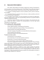
2.
General Information
PST-100HL Plate Shaker-Thermostat is designed for shaking 2 standard 96well microplates in the thermostating mode. Plate Shaker-Thermostat was designed
using the multi-system principle, which allows using it as three independent devices:
1) incubator for lasting incubation of micro quantities (insect, plant cell cultures,
etc.) in plates;
2) microplate Shaker for operation in the cold room or other conditions, which do
not require temperature stabilization;
3) microplate Thermo-Shaker for immunochemistry and molecular diagnostics,
where the requirements to the result reproducibility and thus to the precise method
regulation are particularly high.
A distinctive feature of BioSan plate thermal shakers is the patented two-side
plate heating that allows to achieve full correspondence of the set and actual
temperature in the plate wells.
Thermo-Shaker PST-100HL provides:
soft or intensive sample shaking;
rotation speed regulation, stabilization and indication;
even shaking amplitude throughout Shaker-Thermostat platform;
required operation time setting and indication;
automatic stopping of the platform movement after the set time expires;
current operation time indication;
setting and indication of the required temperature.
The device can be used in:
cytochemistry for in situ reactions;
immunochemistry for immunofermentative reactions;
biochemistry for enzyme and protein analysis;
molecular biology for matrix analysis, DNA and RNA analyses.
The maximum guaranteed number of diagnostic cycles in the Thermo-Shaker
mode, which require 15-30 min work in one cycle, is 7000-14000 times. External 12V
power supply unit is used to power the device. It makes it safe to work in the cold room,
where condensation may cause leakage current from electric circuit.
PST-100HL innovation is appliance of the newest gradient two-cascade
peripherical heating of the platform for two 96-well plates technology. During the
Shaker-Thermostat with heating up to 100°C designing Biosan successfully solved
the problem of high temperature uniformity throughout the whole platform surface in
stable mixing conditions up to 1200 rpm.
Page 5
3.
Getting started
3.1.
Unpacking.
Remove packing materials carefully and retain them for future shipment or
storage of the unit. Examine the unit carefully for any damage incurred during
transit. The warranty does not cover in-transit damage.
3.2
Complete set. Package contents:
PST-100 HL Plate Shaker-Thermostat .................................................1 piece
spare rubber belt ................................................................................2 pieces
external power supply unit .....................................................................1 piece
power cord ............................................................................................1 piece
Operating Manual; Certificate ...............................................................1 copy
3.3.
Set up:
place the unit upon even horizontal non-flammable surface away from any
flammable materials (not less than 30 cm);
remove protective film from the display;
plug the external power supply unit into the socket at the rear side of the unit
and position the unit so that there is easy access to the power switch and the
external power supply unt.
Page 6
4.
Operation
Recommendations during operation
·
Please check the plates before using. Don't heat the plates over the melting
point of the material they are made of.
Caution!
Surfaces of the platform become very hot during the use over
60ºC. To place or remove the microplate use the protective
cotton gloves.
4.1.
Connect the external power supply unit to a grounded power socket and set the
power switch located on the rear panel of the unit to position I ("ON").
4.2.
The display will turn on with the upper line (Set) showing time, speed and
temperature set earlier and the lower line (Actual) showing current readings of
the same parameters (thermoblock temperature °C, which automatically starts
rising according to the temperature set in the upper line). The time of
temperature stabilisation depends on the initial temperature.
4.3.
Setting the parameters. Use the readings in the upper line of the display (Set),
while setting the required parameters.
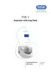
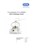
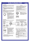
4.3.1. Setting time (TIME). Using the ▲ and ▼ keys (Fig. 1/1) set the required
working time interval in hours and minutes (increment 1 min). Pressing the key
for more than 3 s will increase the increment.
4.3.2. Setting speed (RPM). Using the ▲ and ▼ keys (Fig. 1/2) set the required
shaking speed (increment 10 RPM). Pressing the key for more than 3 s will
increase the increment.
4.3.3. Setting temperature (T,ºC). Using the ▲ and ▼ keys (Fig. 1/3) set the
necessary temperature (increment 0.1ºC). Pressing the key for more than 3 s
will increase the increment.
Caution!
4.4.
The planform heating can be turned off only by setting the
required temperature below 25°C (the display will show OFF T(°C) - Set). It can be used in cold rooms as a mixing device
without thermal regulation in this mode.
Program execution. After the thermal stabilisation of the unit (when the set
and current temperature readings become the same):
4.4.1. Place microplates on the platform and fix it with the special holder by pressing it
against the plate covers.
1
2
3
4
5
Set
Actual
00:00
STOP
1000
000
37.0
37.0
hr : min
Thermo-Shaker
Fig.1 Control panel
Page 7
Caution!
The microplate fixation screw must always be tightened to
avoid damage. Tighten the fixation screw completely when
microplates are removed from or placed on the platform. Do not
close the lid if the microplate fixation screw is not tightened to
avoid damage.
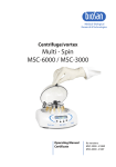
Caution!
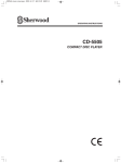
Load only pairs of microplates for best fixing.
Correct loading
Wrong loading
4.4.2. Press the RPM-RUN/STOP key (Fig. 1/4). The platform will start rotating and
the timer indicator will start counting up the time interval (with 1 min precision).
4.4.3. After finishing the program the platform motion will stop and the timer will be
showing the flashing reading STOP accompanied by the repetitive sound signal
until the RPM-RUN/STOP key is pressed.
Caution!
4.5.
At the end of the set time period the platform movement is
stopped automatically, but the heating has to be stopped by
reducing the temperature using the ▼ T(ºC) key (Fig. 1/3 lower
key) till the OFF sign appears in the upper part of the display.
If the working time is not set (or is reset) and the timer indicator in the upper line
shows 00:00, pressing the RPM-RUN/STOP key will start continuous operation
of the Thermo-shaker (timer indicator will start counting up the time interval in
the lower line (Actual)) until the RPM-RUN/STOP key is pressed again.
Note.
The platform temperature will be constantly maintained in
accordance with the set temperature. This allows using the
device again without pre-heating.
4.6.
The timer can be reset during operation if required. Press the TIME-RUN/STOP
key once (Fig. 1/5) to stop the timer. Press the TIME-RUN/STOP key again to
restart the timer.
4.7.
The platform motion can be stopped at any time by pressing the RPM-RUN
/STOP key. In this case the program realisation and the platform motion will
stop and the timer will switch into the STOP mode saving previously set time.
Press the RPM-RUN/STOP key to repeat the operation with the same time and
speed.
4.8.
When lid is open the platform and lid heating surfaces will remain hot. Please,
take necessary care and use protective cloth gloves at temperatures over
60°C.
4.9.
After finishing the operation set the power switch, located on the rear panel of
the unit, in position O (Off) and disconnect the external power supply from
electric circuit.
Page 8
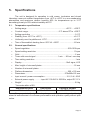
5.
Specifications
The unit is designed for operation in cold rooms, incubators and closed
laboratory rooms at ambient temperature from +4ºC to +40ºC in a non-condensing
atmosphere and maximum relative humidity 80% for temperatures up to 31°C
decreasing linearly to 50% relative humidity at 40°C.
5.1.
Temperature specifications
·
Setting range ........................................................................+25°C ... +100°C
·
Ccontrol range..........................................................5°C above RT to +100°C
·
Setting resolution ...................................................................................0.1ºC
·
Stability (from +25°C to +60°C) ............................................................±0.1°C
·
Uniformity over the platform at +37ºC...................................................±0.2ºC
·
Time of thermoblock heating from +25ºC till +100ºC ...........................60 min
5.2.
General specifications
·
Speed regulation ......................................................................250-1200 rpm
·
Speed setting resolution ..................................................................... 10 rpm
·
Orbit .......................................................................................................2 mm
·
Timer with sound signal .........................................1 min … 96 hrs / non-stop
·
Time setting resolution ...........................................................................1 min
·
Display ..................................................................................16x2 signs, LCD
·
Max. height of microwell plates ............................................................18 mm
·
Number of microwell plates ...........................................................................2
·
Platform dimensions ...............................................................250 x 150 mm
·
Dimensions .........................................................................270x260x125 mm
·
Input current / power consumption .........................................12 V, 5 A / 60 W
·
External power supply .............input AC 100-240 V 50/60Hz, output DC 12 V
·
Weight* ..................................................................................................5.9 kg
* Accurate within ±10%.
Replacement parts
Description
Catalogue number
Rubber belt
122 x 6 x 0.6 mm
BS-000000-S18
Company retains the right to make changes and supplements in product design
aimed at enhancement of consumer performance and operation quality without prior
notice.
Page 9
6.
Maintenance
6.1.
If the unit requires maintenance, disconnect the unit from the electric circuit and
contact Biosan or your local Biosan representative.
6.2.
All maintenance and repair operations must be performed only by qualified and
specially trained personnel.
6.3.
Standard ethanol (75%) or other cleaning agents recommended for cleaning of
laboratory equipment can be used for cleaning and decontamination of the unit.
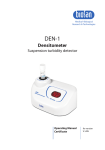
6.4.
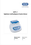
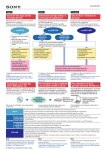
Rubber belt replacement.
For maintenance of reliable operation of the device the producer recommends
to replace rubber belts after 1.5 years or 2000 hours of operation time.
Disconnect the external power supply unit from
the device.
Remove 4 fixation screws on the divece bottom
and remove the bottom plate.
ll
llllll
lllllllll
l
l
ll
lllll
ll
lll
ll l l l l l l l
ll
Re-assemble the device.
lll
ll
Replace the rubber belt (fig.2).
ll
Fig.2 Rubber belt
replacement
7.
Warranty and Claims
7.1.
The Manufacturer guarantees the compliance of the unit with the requirements
of Specifications, provided the Customer follows the operation, storage and
transportation instructions.
The warranted service life of the unit from the date of its delivery to the
Customer is 24 months. Contact to your local distributor to check availability of
extended warranty.
If any manufacturing defects are discovered by the Customer, an unsatisfactory
equipment claim shall be compiled, certified and sent to the local distributor
address. Please visit www.biosan.lv, Technical support section to obtain the
claim form.
The following information will be required in the event that warranty or postwarranty service comes necessary. Complete and retain for your records.
7.2.
7.3.
7.4.
Model
Serial number
Date of sale
Page 10
PST-100HL Plate Shaker-Thermostat
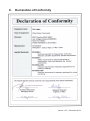
8.
Declaration of Conformity
Version 1.03 - December 2014