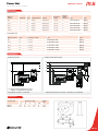
1
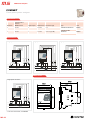
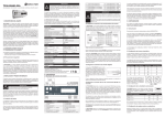
Measurement and electric control CVM Power analyzers CVM Power analyzers M.5 - CVM Power analyzers CVMk2 Three-phase power analyzer(balanced and unbalanced) for panel or DIN rail mounting . . . . . . . . . . . . . . . . . . . . . . . . . . . M5-8 MP3 / MP4 Three-phase power analyzers . . . . . . . . . . . . . . . . . . . . . . . . . . . . . . . . . . . . . . . . . . . . . . . . . . . . . . . . . . . . . . . . . . . . . . . . . . . M5-14 CVM NRG 96 Three-phase power analyzer (balanced and unbalanced) for panel mounting . . . . . . . . . . . . . . . . . . . . . . . . . . . . . . . . . . . M5-17 CVM MINI Three-phase power analyzer (balanced and unbalanced) for DIN rail mounting . . . . . . . . . . . . . . . . . . . . . . . . . . . . . . . . . M5-19 CVM NET Three-phase power analyzer (balanced and unbalanced) for DIN rail mounting - without display . . . . . . . . . . . . . . . . . . M5-21 CVM-NET-4 4 Three-phase power analyzers in one, for DIN rail mounting - without display . . . . . . . . . . . . . . . . . . . . . . . . . . . . . . . . . M5-23 CVM-1D Single-phase power analyzer for DIN rail mounting . . . . . . . . . . . . . . . . . . . . . . . . . . . . . . . . . . . . . . . . . . . . . . . . . . . . . . . . M5-25 CVM 96 Three-phase power analyzer(balanced and unbalanced) for panel mounting . . . . . . . . . . . . . . . . . . . . . . . . . . . . . . . . . . . M5-27 CVM 96 Three-phase power analyzer(balanced and unbalanced) for panel mounting . . . . . . . . . . . . . . . . . . . . . . . . . . . . . . . . . . . M5-28 CVM 144 Three-phase power analyzer(balanced and unbalanced) for panel mounting . . . . . . . . . . . . . . . . . . . . . . . . . . . . . . . . . . . M5-29 CVM BD Three-phase power analyzer(balanced and unbalanced) for DIN rail mounting . . . . . . . . . . . . . . . . . . . . . . . . . . . . . . . . . . M5-32 CVM BDM Three-phase power analyzer(balanced and unbalanced) for DIN rail mounting, with internal 1 MB memory . . . . . . . . . M5-34 Power Net Three-phase power analyzer . . . . . . . . . . . . . . . . . . . . . . . . . . . . . . . . . . . . . . . . . . . . . . . . . . . . . . . . . . . . . . . . . . . . . . . . . . . M5-36 TR8 Multi-channel DC voltage and current analyzer . . . . . . . . . . . . . . . . . . . . . . . . . . . . . . . . . . . . . . . . . . . . . . . . . . . . . . . . . . . . M5-38 TR16 Multi-channel voltage and DC analyzer for photovoltaic strings . . . . . . . . . . . . . . . . . . . . . . . . . . . . . . . . . . . . . . . . . . . . . . M5-40 Accesories TCP2RS+ Converter of RS-232 / RS-485 to Ethernet Modbus . . . . . . . . . . . . . . . . . . . . . . . . . . . . . . . . . . . . . . . . . . . . . . . . . M5-42 CAMO RS-232 - RS-485 converter / amplifier . . . . . . . . . . . . . . . . . . . . . . . . . . . . . . . . . . . . . . . . . . . . . . . . . . . . . . . . . . . . . . M5-43 USB Converter to RS-232 or RS-485 . . . . . . . . . . . . . . . . . . . . . . . . . . . . . . . . . . . . . . . . . . . . . . . . . . . . . . . . . . . . . . . . . . . . . M5-44 Front panel adaptor . . . . . . . . . . . . . . . . . . . . . . . . . . . . . . . . . . . . . . . . . . . . . . . . . . . . . . . . . . . . . . . . . . . . . . . . . . . . . . . . . . . M5-44 M5-2 CVM Power analyzers CVM Power analyzers Nowadays, companies, industries or any consumer of electrical energy are trying to optimise costs to become the most competitive players in the market. We can act over a large number of parameters to save on costs, such as on the consumption of electrical energy. CIRCUTOR's analyzers offer state-ofthe-art technology, measuring a large variety of electrical parameters, with the main purpose of controlling and managing an installation, machine, industry, etc. thus optimising the energy costs. M.5 Definition The CVM series of analyzers includes highly accurate metering stations that are aimed at the control and supervision of the main electrical parameters in three or four-wire, low and high voltage, single and/or three-phase grids. In addition, they offer the most innovative technologies and offer metering in true root mean square. Its indirect current outputs use ITF technologies in the .../5 A secondary or .../1 A or efficient transformers MC1 and MC3.../250mA secondary: galvanic insulation protection inputs What functions analyzers offer? do CIRCUTOR's }}They display and transmit all electrical parameters metered and/or calculated. }}They incorporate the metering function, storing in the memory the value of energy consumed and generated, even in the absence of an auxiliary power supply. Hourly discriminator with previous programming mode, thus obtaining a totalizer of active, apparent, reactive inductive and reactive capacitive energy, for each rate programmed (depending on the type).They incorporate the maximeter function, calculating the demand integrated in a programmable period (depending on the type). The integration is carried out with a sliding window and it can be carried out over the following adjustable parameters: three-phase current, active three-phase power, apparent three-phase power or current per phase. }}Some of CIRCUTOR's analyzers can be expanded or offer modular capabilities, with additional functions that can be associated to any electrical parameter monitored or calculated, such as: M5-3 CVM Power analyzers }}Multi-converter functions: analogue inputs and outputs. }}Alarm station or impulse generation function: digital inputs and outputs. The communications outputs, connection topologies and network protocols can be of different types. }}Connections: Ethernet, RS-232, RS485, RF }}Protocols: Modbus TCP, Modbus RTU, Profibus DP, Metasys N2 and XML. INTEGRATION OF COMMUNICATIONS IN ANALYZERS Communications let you make the most of the metering equipment in combination with PowerStudio, CIRCUTOR’s energy monitoring and supervision software. RS-485 communications can be used to make the most out of CIRCUTOR's analyzers with the management software, reading all parameters metered and calculated in real time. The PowerStudio Scada software not only displays the electrical parameters in real time, but it also generates a database in the PC, where it stores the log of values, which can be studied later on. CIRCUTOR offers a range of analyzers, which have Ethernet communications, so they can be connected directly to the intranet and Internet. Therefore, their integration with the PowerStudio software is quick and easy. In addition, CIRCUTOR offers Profibus analyzers, which can access a large variety of industrial automation applications, where the protocol is commonly used. Integration systems (Modbus RTU vs. Modbus TCP) Until now, CIRCUTOR offered and is currently offering Ethernet communication gateways, (Modbus RTU), (TCP2RS+ code M54033), used for the integration of RS-485 equipment, making use of the Ethernet infrastructures existing in installations. Said M5-4 gateways were designed for the communication with market SCADAs that did not have the possibility of establishing IP addressing communications, since this was through a virtual port redirectioning software. Another problem with this type of communications was that it was a mono-master system, i.e., communications could only be established with slave equipment, with a single master or control PC. Communications could not be established with other equipment that was not established as a slave. Fortunately, PLC data acquisition systems and other market masters, as well as the slaves commonly installed in these cases (three-phase power quality analyzers) have been unified under a standardised protocol that is very popular among manufacturers: Industrial Ethernet or Modbus/TCP.The implementation of this system has led to the standardisation of the protocol so that any slave can be queried by various masters at the same time (up to eight), thus multiplying the different and diverse communication topologies in an energy control installation or in any process control situation (multimaster cases).Therefore, CIRCUTOR has launched its range of Ethernet analyzers again, implementing the new protocol with the main purpose of standardising the communication methods used by most of the global manufacturers. }}CVMk2-ITF + k2-EXP-SD-MODBUS/ TCP: Power Quality Analyzer M54400 / M54402 + Ethernet expanding module (Modbus/TCP) M54504 }}CVM144-ITF-Ethernet-TCP: Power Quality Analyzer (Modbus/TCP): M50790 }}CVM96-ITF-Ethernet-TCP: Power Qual- ity Analyzer (Modbus/TCP):M51241 }}TCP2RS+: Converter RS-232-RS-485 / Ethernet (Modbus/TCP): M54033 }}LM50-TCP+: Alarm / Impulse Centralizer (Modbus/TCP): M31566 With this type of analyzers, the integration of CIRCUTOR's units with any market SCADA, PLC or control master is easier and simpler than ever. CVM Power analyzers ENERGY MANAGEMENT SOFTWARE: Power Studio Scada Toph-pherformance management software designed for the analysis of the consumption of energy and other parameters metered by CIRCUTOR's equipment. What can this software be used for? }}Control of the energy in an installation, analysing the status of its lines and installations in real time. }}Simulation of receipts, depending on the version. It can be used to analyse the consumption of energy in the installations with the equipment supplied by CIRCUTOR and it also enables the simulation of bills, defining different rates, whether they are regulated or not. }}Study of the evolution of electrical parameters in time, such as: V, A, kW, etc, with graphs and tables. Data and graphs can be exported to draw up reports. Different analyzers can be used to analyse and study the quality parameters defined by the IEC 61000-4-30 Standard. Applications Supervision and preventive maintenance of an installation, with the real-time and log of the status and consumption of all sorts of low and medium voltage (LV and MV) machines and installations. M5-5 CVM Power analyzers Product selection table CVMk2 METERING FEATURES L1 L2 L3 Single phase voltage * * * Phase-phase voltage * * * MP3 / MP4 N III L1 L2 L3 * * * * CVM NRG96 III CVM MINI III CVM NET L1 L2 L3 L1 L2 L3 L1 L2 L3 * * * * * * III * * * * * * * * * * * * * * * * * * * * * * Vref Voltage (GND)-NEUTRAL Current * Frequency * Active power * * * Reactive power L * * * Reactive power C * * * * Apparent power * * * * * * * * Power factor * * * * * * * * cos j * * * * * * * * * * * * * * * * * * * * * * * * * * * * * * * * * * * * * * * * * * * * * * * * * * * * * * * * * * * * * * * * * * * * * * * * * * * * * * * * Maximum active power demand Maximum apparent power demand * * * * * * * * * * * * * * * * * * * ** * * * * * * * * * * * * THD Voltage * * * * * * * * * * * * * THD Current * * * * * * * * * * * * * Voltage harmonics (depending on the type (*) * * * * 50 * * * 15 * * * Current harmonics (depending on the type (*) * * * * 50 * * * 15 * * * Neutral current * * * * Maximum current demand III * * * * * * 15 15 Active energy * * * * * * * * Reactive energy L * * * * * * * * Reactive energy C * * * * * * * * Apparent energy * * * * * Flicker (WA and PST) * * * Factor K (current) * * * Peak factor (voltage) * * * Unbalance (voltage and current) * * * Asymmetry (voltage and current) * * * Rates (depending on the type) 9 1 Analogue inputs (0/4...20 mA) * * 1 1 1 Analogue outputs (0/4...20 mA) * * Digital inputs * * Digital outputs T /R T T T T Measure points (Voltage/Current) 1/1 1/1 1/1 1/1 1/1 RS-485 * * * * * Ethernet * * * * * * * * * * M5-8 M5-14 M5-17 M5-19 M5-21 COMMUNICATIONS FEATURES RS-232 COMMUNICATIONS PROTOCOL Modbus RTU * Modbus TCP * Profibus DP * Johnson Controls Compatible with PowerStudio SCADA Page Possible parameters, depending on the unit selected. * Available for display and communications ** Available only for communications. (*) Harmonic decomposition in HAR types. M5-6 CVM Power analyzers CVM NET4 L1 L2 L3 * * * * * * * * * CVM1D III * * L1 CVM 96 CVM 144 III CVM BD L2 L3 L1 L2 L3 L1 L2 L3 L1 L2 L3 L1 L2 L3 * * * * * * * * * * * * * * * * * * * * * * * * * * * * * * * * * * * * * * * * * * * * * * * * * * * * * ** * III Power Net L1 ** III CVM BDM * * III * * III * * * * * * * * * * * * * * * * * * * * * * * * * * * ** ** ** * * * * * * * * * * * * * * * * * * * ** ** ** ** * * * * * * * * * * * * * * * * * * * * * * * * * * * * * * * * * ** * * * * * * * * * * * * * * * * * * ** * * * * * * * * * * * * * * * * * * * - * * * * * * * * * * * * * * * * * * * * * * * * * * * * * * * * * * * * ** ** ** 15 ** ** ** 15 ** ** ** 31 * * * 31 * * * * * * * * * * * * * * * * * * * * * ** * 1 1 1 * * * 1 * ** * * * * * * * 3 1 * * * * * T T R R R R 1/1 1/1 1/1 1/1 1/1 1/1 1/1 * * * * * * * * * * * * * * * * * * * * * * * M5-23 M5-25 * * * * * * M5-27 M5-29 M5-32 * M5-34 M5-36 Possible parameters, depending on the unit selected. * Available for display and communications ** Available only for communications. (*) Harmonic decomposition in HAR types. M5-7 CVM Power analyzers CVMk2 Three-phase power analyzer(balanced and unbalanced) for panel or DIN rail mounting Description Three-phase power analyzer (balanced and unbalanced) for its assembly on panel or DIN rail mounting with a graphical display. measuring in 4 quadrants. Other features include: }}Class 0.2 or 0.5 power and energy }}Measuring of Class B supply quality events (guaranteeing the power supply of the unit with an UPS, battery, etc.) }}Current measuring .../5 or .../1 A }}Measure of neutral current with transformer }}Optional energy consumption and generation billing (up to 9 rates) }}RS-485 Modbus/RTU Communications }}Expansion possibilities (up to 3 modules) }}Backlit graphical display }}Instantaneous display of maximum and minimum electrical parameters with date and hour }}Measure of energy consumed and generated, up to 100 GW·h }}Universal series power supply }}With ITF technology: galvanic insulation protection inputs Application }}Applied to the control of general switchboards and low, medium and high voltage connection points }}Alarm station with voltage-free digital inputs }}Submetering station: impulse meter with other types of consumption, such as gas, water, steam, etc. with their digital inputs }}Measuring converter: optional association of an instantaneous parameter to one of the analogue outputs available (0...20 mA / 4...20 mA) }}Instantaneous, maximum and minimum parameter recording unit, with date and hour and an expandable memory card }}Power quality analyzer: harmonic decomposition up to order 50º, asymmetries, flicker, unbalances, overvoltages, gaps, interruptions, etc. Features Power supply circuit 85...265 V ac / 90...300 V dc ac Power supply frequency 50..0.60 Hz ac Power supply consumption 30 V·A dc Power supply consumption < 25 W Metering circuit Nominal voltage 300/500 V ph-n / V ph-ph or 500/866 V ph-n / V ph-ph Frequency 45..0.65 Hz Metering margin 5...120 % of the Un for Un= 300 V ac (ph-n) 5...120 % of the Un for Un= 500 V ac (ph-n) Maximum metering voltage 360 V ac Admissible overvoltage 750 V ac Maximum consumption (limited current) < 0.6 V·A Current measuring circuit Nominal current .../5 A or .../1 A Metering margin 1..0.120 % of In for In = 5 A Primary current metered Programmable <30,000 A Admissible overload 6 A permanent, 100 A t < 1 s Consumption < 0.45 V·A Maximum meter value 100 GW·h Class/Accuracy 0.2 or 0.5 power and energy Ambient conditions Operating temperature -10 ... +50 ºC Relative humidity 5 ... 95% Altitud 2000 m Build features Metering module Assembly on DIN Rail 46277 (EN 50022) Screen or screen + metering module Assembly on panel (96 x 96 mm, 144 x 144 mm) or opening with a 103 mm diameter External dimensions 144 x 144 x 116 mm Safety Designed for CAT III 300/520 Vac installations, in accordance with EN 61010 Double-insulated electric shock protection, class II Standards IEC 61000-4-2, IEC 61000-4-3, IEC 61000-4-11, IEC 61000-4-4, IEC 61000-4-5 M5-8 CVM Power analyzers CVMk2 Three-phase power analyzer(balanced and unbalanced) for panel or DIN rail mounting References Compact units (metering + display module) Quadrants Class Communications MODBUS / RTUProtocol 4 0,5 RS-485 Yes Yes CVMk2-ITF-405 M54400 4 0,5 RS-485 Yes Yes CVMk2-ITF-402 M54402 Neutral current Universal power supply Type Code Neutral current Universal power supply Type Code Measuring units (measuring module) Quadrants Class Communications MODBUS / RTUProtocol 4 0,5 RS-485 Yes Yes M-CVMk2-ITF-405 M54410 4 0,5 RS-485 Yes Yes M-CVMk2-ITF-402 M54412 Connections Connection (5 wires) of 4 Current transformers Connection of 4 Current transformers and 2 voltage transformers Connection of 3 Current transformers (3 wires) Dimensions Fig. 1 Fig. 2 Fig. 3 Figures 1, 2 and 3: Display of the frontal panel part embedding (display) in a 92 x 92 mm opening, with a diameter of 110 mm and 138 x 138 mm, respectively M5-9 CVM Power analyzers Exchangeable modules CVM k2 1. k2-EXP-8I / 8O-Digital-TR Card Card with 8 digital inputs and 8 digital outputs of transistor Features Features Connection Logical inputs Type of input Voltage-free Type of coupling Optoinsulated V max 24 V dc minimum t ON / t OFF t ON 40 ms t OFF 40 ms Static outputs AC Voltage <100 Vac Non-repetitive Peak voltage 350 V pk. Nominal current 100 mA Repetitive current during t=1s 120 mA Maximum current t=10 ms 350 mA Connection Connection Rigid conductor section 0.05...1 mm2 Code M54501 2. k2-EXP-8I / 4O-Digital-RL Card Card with 8 digital inputs and 4 digital outputs. Outputs with relay. Features Features Logical inputs Type of input Voltage-free Type of coupling Optoinsulated V max 24 Vdc minimum t ON / t OFF t ON 40 ms t OFF 40 ms Relay outputs AC Voltage 250 Vac AC Current 6 Aac Minimum relay load 1 Vac 0.001 Aac Mechanical working life 5 x 10⁶ operations Electrical working life NO: 5x10⁴, NC: 3x10⁴ cycles Connection M5-10 Rigid conductor section 0.05...1 mm2 Code M54503 Connection CVM Power analyzers Exchangeable modules CVM k2 3. k2-EXP-8I / 4O-Analogue Card Card with 8 digital inputs and 4 digital outputs Connection Features Features Analogue outputs Maximum internal voltage 20 / 24 Vdc Output range 0 / 4...20 mA Linearity 1% Load resistance < 500 ohm Output range 4000 points Connection Analogue inputs Type of metering - Input range 0 / 4...20 mA Metering accuracy 1% Input impedance 200 ohm Connection Rigid conductor section 0.05...1 mm2 Code M54502 4. k2-EXP-SD Card Ethernet communications card and SD memory Features SD Card Type of card SD Maximum capacity 2 Gb Format FAT 16 Code M54506 Recommendations Icons xxCorrect SD memory state Card used to record up to 400 electrical variables coming from a CVMk2 power quality analyzer. It also includes a log of the quality events: overvoltages, voltage interruptions or gaps. xxIncorrect SD memory state xxSD Card removal enabled M5-11 CVM Power analyzers Exchangeable modules CVM k2 5. PROFIBUS Card GSD Modules The GSD modules are configured in accordance with the following table. The table shows the module number, content (variables) and the total size of the module. Mod. 1 Parameters Byte Simple voltages 12 Phase currents 12 Compound voltages 12 Power factor 12 Size 52 Frequency 4 2 Power ratings 48 Mean values 12 3 Neutral values 8 Three-phase values 24 4 Current energy with no billing 48 48 5 THD U / I 32 32 6 THD odd / even 64 64 7 Unbal / Asymmetry / Flicker 44 44 8 Odd harmonics, Voltage (15º) 72 72 9 Even harmonics, Current (15º) 72 72 10 Digital I. 1 / Analogue I. 2 64 64 11 Digital I. 2 / Analogue I. 3 64 64 12 Digital I. 3 / Analogue I. 1 64 64 13 Cos φ 12 12 48 44 Code M5450A 6. k2-EXP-SD-MODBUS/TCP Card Ethernet communications card and SD memory Features Ethernet output Network Protocol Ethernet RJ-45 Communication protocol Modbus / TCP Speed compatible with 10 base T / 100 base Tx SD Card Type of card SD Maximum capacity 2 Gb Format FAT 16 Code M54504 Icons Recommendations xxThe unit is formatted automatically when installing an SD card. Do not install cards with contents stored that you wish to keep. xxTo remove the SD card safely, interrupt the communications between the unit and the memory. There are two ways to do so; either turning the unit off or accessing the card setup menu. M5-12 xxCorrect SD memory state xxIncorrect SD memory state xxSD Card removal enabled CVM Power analyzers Exchangeable modules CVM k2 7. Exp. Card 4 S analogue + 4 S static. ±5 mA Features Features Logical outputs Output range ±5 mA Linearity 1% Load resistance < 1000 Output range 4000 points Connection Static outputs Voltage <100 Vac/Vdc Non-repetitive Peak voltage 350 V pk. Nominal current 100 mA Repetitive current during t=1s 120 mA Maximum current t=10 ms 350 mA Connection Rigid conductor section 0.05...1 mm2 Code M54507 Connection A. 1- COMMON 2- Analogic output 3- COMMON 4- Analogic output 5- COMMON 6- Analogic output 7- COMMON 8- Analogic output 9- Not used T. 1 2 3 4 123456789- COMMON COMMON COMMON COMMON COMMON Transistor Transistor Transistor Transistor output output output output 1 2 3 4 M5-13 CVM Power analyzers MP3 / MP4 Three-phase power analyzers Description }}MP3-P and MP4-P are measuring equipment models that fulfil the functions of power analyzers and earth leakage protection relay in just one unit. They also have the advantage of having measuring transformers and the earth leakage transformer incorporated into one unit. }}Communications RS 485 ModbusRTU }}Optional display LCD. }}2 digital inputs }}2 relay outputs }} 2 energy impulse outputs }}Conductor section with power of 120-185 mm without adaptor and 35-95 mm with adaptor }}Possibility of 2 additional relay outputs (optional) }}Possibility of 1 additional analogue output (optional) }}Compatible with the energy management software: PowerStudio, PowerStudio Scada and PowerStudio Scada Deluxe Application }}It's specially designed equipment for assembly in electrical panels. It's been designed to be compatible with any automatic switch on the market. }}Earth leakage protection in the electrical panel. }}Control of instantaneous values and the recording of maximums and minimums of the measured electrical parameters. M5-14 Features Power circuit Voltage 18 - 36 V cc Maximum power consumption 200 mA Connector Phoenix Contact® GMVSTBR 2,5-2-ST-7,62 Voltage measurement Nominal voltage 690 V ca Maximum voltage 800 V ca Maximum impulse voltage 8/20 us 8000 V Impedance 1 MΩ Frequency 45 - 65 Hz Accuracy 0.4% measurement + 0.1% FS Category EN61010 CAT IV-600 V Current measurement Nominal current 250 A ca Maximum current 300 A ca Maximum impulse current 1s 30 kA Frequency 45 - 200 Hz Accuracy 0.45% measurement + 0.05% FS Category EN61010 CAT IV-600 V Power measurement / energy Maximum power (per phase) 240 kW Accuracy 0.95% measurement + 0.05% FS Active energy accuracy Class 1 (IEC62053-21) Reactive energy accuracy Class 2 (IEC62053-23) Pulse output Type Isolated solid-state relay VCE max 350 V VCE sat 120 mA IC recommended 10 mA Insulation 3 kV - EN61010 CAT III 300 V Maximum frequency 4 Hz Minimum pulse width 20 ms CVM Power analyzers MP3 / MP4 Three-phase power analyzers Features Application Digital output }}Fully programmable alarm function for any electrical parameter measured by the unit. }}Control of active and reactive energy using impulse output. }}Incorporation of measurements and earth leakage protection in SCADA systems through its communications Type Isolated solid-state relay Umax 350 V Imax 120 mA Insulation 2.5 kV - EN61010 CAT III 300 V Digital input Umax 50 V Imax 300µA (U<15V) Imax 4 mA (U<24V) Imax 15 mA (U<48V) V 3V31 IH max Modbus output - RS-485 Speed (bps) 9600, 19200, 38400 Stop bits 1.2 Parity None, even, odd Insulation 2.5 kV - EN61010 CAT III 300 V Modbus output - Display Power Supply 5 dc, max 180 mA Speed (bps) 9600, 19200, 38400 Stop bits 1.2 Parity None, even, odd Environmental specifications Operating temperature -15 – 65 °C Storage temperature -40 - 80 °C Humidity (without condensation) 5 - 95% Maximum operating height 2000 m IP protection IP20 Build features MP3 MP4 Dimensions 209 x 91 x 132 mm 251 x 91 x 132 mm Weight 850 g 975 g Material UL94-V0 Standards EN -61010: Double-insulation electric shock protection, class II R eferences MP series. Direct connection analyzers and bushing bar assembly for installations on 250/400 A switches Current 250 A 400 A 250 A Three-phase installation Power Supply Inputs / outputs Impulse output Communications 3 wires 24 V cc 2 2 RS-485 4 wires 24 V cc 2 2 RS-485 Type Code MP3-250-P M54A4300A MP3-400-P M54A2300A MP4-250-P M5494300A MP4-400-P M5492300A Visual display, 96 x 96 mm in size D-MP M54A01 Source of power supply 24 V cc / 230 V ca PS-MP-24 V cc M54A02 400 A M5-15 CVM Power analyzers MP3 / MP4 Three-phase power analyzers Features }}2 Impulse outputs Max. 185 mm2 Mín. 120 mm2 }}2 Digital inputs }}2 Programmable rrelais outputs Max. 95 mm2 Mín. 35 mm2 Max. 25 mm Mín. 12 x 2 mm Dimensions MP3 250 MP4 250 125x87x132 mm 160x87x132 mm MP Power analyzers MP3 400 MP4 400 209x91x132 mm 251x91x132 mm Earth leakage protection relay The MP series can use its 2 RS-485 communications ports to several advantages. In addition to the optional incorporation of a D-MP display model for visualizing the data measured by the unit on site, it can use the other port to incorporate the unit in a SCADA energy management application. The CIRCUTOR software designed for energy management and supervision is PowerStudio SCADA, which enables data processing and remote management of the unit. MP3 Display D-MP CVMk2 MP4 TCP2RS+ MP3 D-MP CVM-MINI }}Example of an installation where the metering and protection below the automatic switch is carried out with MP. M5-16 CVM-MINI CVM-MINI CVM Power analyzers CVM NRG 96 Three-phase power analyzer (balanced and unbalanced) for panel mounting Description Three-phase power analyzer (balanced and unbalanced) for its assembly on panels with a minimum depth, measuring in 4 quadrants. }}Other features include:Class 0.5 energy }}Current measure .../5 }}RS-485 Modbus/RTU Communications, depending on the type }}Instantaneous, maximum and minimum parameter display }}Digital output with optoinsulated transistor }}ITF Technology: Galvanic insulation protection inputs inputs, depending on the type }}Maximeter function (A / A III / kW III / kV·A III) }}Default page selection }}Universal power AC and DC optional Features Power supply circuit dc Version Plus Version: ac and dc 24 Vdc (-15...+10%) 85...265 V ac / 95...300 V dc AC Power supply frequency - 50...60 Hz (ac type) Maximum consumption (equipment with communications) 2.2 W 2 V·A DC Power supply consumption (equipment w/o communications) 1.8 W 2 V·A Metering circuit Nominal voltage 300 Vac (ph-n) / 520 Vac (ph-ph) Frequency 45..0.65 Hz Nominal current In .../ 5 A Current consumption of the circuit 0.75 V·A Overload (permanent) 1.1 In Class/Accuracy Voltage 0.5 % ± 2 digits Current 0.5 % ± 2 digits Power rating 1 % ± 2 digits Ambient conditions Application }}Applied to the control of switchboards and low and medium voltage connection points. }}Alarm control, with full programming of the variable controlled, maximum and minimum values and the delay }}Control of active or reactive energy with pulses }}Control of instantaneous, maximum and minimum values of the electrical parameters metered Operating temperature -10 ... +50 ºC Relative humidity 5 ... 95% Output transistor Optoinsulated (collector open) NPN Maximum switching voltage 24 Vdc Maximum switching current 50 mA Maximum impulse frequency 5 impulse / s Duration of the impulse 100 ms Build features Type of box Degree of protection Dimensions VO self-extinguishing plastic Fitted unit (frontal): IP 51 Non-fitted unit (sides and rear cover): IP 31 96 x 96 x 63 mm Safety Designed for CAT III 300/520 Vac installations, in accordance with EN 61010. Double-insulated electric shock protection, class II Standards IEC 664, VDE 0110, UL 94, IEC 801, IEC 348, IEC 571-1, EN 61000-6-3, EN 61000-6-1, EN 61010-1 M5-17 CVM Power analyzers CVM NRG 96 Three-phase power analyzer (balanced and unbalanced) for panel mounting References Quadrants Class (V, A) Communications Digital output Universal power supply Harmonics 4 0,5 - - Yes - Type Code CVM-NRG 96 M51800 4 0,5 - - Yes - CVM-NRG 96-ITF M51900 4 0,5 RS-485 1 Yes - CVM-NRG 96-ITF, RS-485 C M51911 4 0,5 RS-485 1 Yes U and I (15º) CVM-NRG 96-ITF-HAR, RS-485 C M51B11 4 0,5 LonWorks 1 Yes - CVM-NRG 96-ITF-LonWorks-C M51951 4 0,5 BACnet 1 Yes - CVM-NRG 96-ITFBACnet-C M51981 CVM NRG96-MC, Sistemas de medida Eficiente 4 0,5 - - Si - CVM NRG96-MC-ITF M52070 4 0,5 RS-485 1 Si - CVM NRG96-MC-ITF-RS-485-C2 M52081 Type Code MC1 single-phase and MC3 three-phase Efficient Transformers, MC Series* Max. A Ranges Class 0,5 Power Measurement Internal diameter 63 - 0,1 VA 3 Phases 7,1 mm MC3-63 M73121 125 - 0,1 VA 3 Phases 14,6 mm MC3-125 M73122 250 - 0,25 VA 1 Phase 26 mm MC3-250 M73123 250 150/200/250 0,25 VA 1 Phase 20 mm MC1-20-150/200/250 M73113 500 250/400/500 0,25 VA 1 Phase 30 mm MC1-30-250/400/500 M73114 1500 500/1000/1500 0,25 VA 1 Phase 55 mm MC1-55-500/1000/1500 M73115 * Mas información sobre transformadores eficientes consulte M7 Dimensions Coding table M 5 X X X X 0 X Internal Code Code Power Supply Voltage (PSV) 0 Standard (230 Vac) 0 85...265 Vac 95...300 Vdc A 24..0.120 Vdc 5 Connections CVM NRG96, 3 or 4 wires (low voltage) Vaux. M5-18 CVM NRG96, 3 wires (2 Voltage transformers and 3 Current transformers) Vaux. CVM NRG96, 3 wires (2 Voltage transformers and 2 Current transformers) Vaux. CVM Power analyzers CVM MINI Three-phase power analyzer (balanced and unbalanced) for DIN rail mounting Description Three-phase power analyzer(balanced and unbalanced) for its assembly on DIN rails with very small dimensions, measuring in 4 quadrants. Other features include: }}Current measuring .../5 or .../1 A }}DIN rail format with only 3 modules }}Assembly on the 72 x 72 mm panel with frontal adaptor (cod. M5ZZF1) }}RS-485 Communications (Modbus-RTU) }}Two transistor outputs }}ITF technology: galvanic insulation protection inputs inputs, depending on the type }}Selection of parameters displayed }}Default page selection }}Universal power supply for the Plus type }}Sealable Application }}Application for the control of switchboards and low and medium voltage connection points, where an analyzer must be installed on the DIN rail due to space restrictions. }}Control of instantaneous, maximum and minimum values of the electrical parameters metered. Features Power supply circuit 230 V ac (-15...+10%) Plus: 85..0.265 V ac / 95...300 V dc Consumption 3 V·A Frequency 45...65 Hz Metering circuit Nominal voltage 300 V ac (ph-n) / 520 Vac (ph-ph) Frequency 40..0.65 Hz Voltage consumption of the circuit 0.7 V·A Current consumption of the circuit ITF 0.9 / Shunt 0.75 V·A Transformadores .../5 A ó.../ 1 A / 250 mA Minimum direct current 110 mA Maximum direct current 6A Maximum current con transformador In /5 1,2 In Class/Accuracy Voltage 0.5 % ± 1 digit Current 0.5 % ± 1 digit Power rating 1 % ± 1 digit Ambient conditions Operating temperature -10 ... +50 ºC Relative humidity (non-condensing) 5 ... 95% Altitud 2000 m Output transistor Optoinsulated (collector open) NPN Maximum switching voltage 24 V dc Maximum switching current 50 mA Maximum impulse frequency 5 impulse / s Duration of the impulse 100 ms / 100 ms Build features Type of box Degree of protection VO self-extinguishing plastic Embedded equipment: IP 41 Terminals: IP 20 Dimensions 52.5 x 85 x 67.9 mm (3 modules) Weight 210 g Safety Designed for CAT III 300/520 Vac installations, in accordance with EN 61010. Double-insulated electric shock protection, class II Standards IEC 664, VDE 0110, UL 94, IEC 801, IEC 348, IEC 571-1, EN 61000-6-3, EN 61000-6-1, EN 61010-1 M5-19 CVM Power analyzers CVM MINI Three-phase power analyzer(balanced and unbalanced) for DIN rail mounting References Quadrants Class (V, A) Communications Protocol Digital output Harmonics Type Code 4 0,5 - - - - CVM-MINI M52000 4 0,5 - - - - CVM-MINI-ITF M52010 4 0,5 RS-485 MODBUS / RTU 2 - CVM-MINI-ITF-RS-485-C2 M52021 4 0,5 RS-485 MODBUS / RTU 2 V and I (15º) CVM-MINI-ITF-HAR-RS-485-C2 M52031 4 0,5 RJ-45 MODBUS/TPC 2 - CVM-MINI-ITF-ETHERNET-C2 M520J1 4 0,5 - BACnet 2 - CVM-MINI-ITF-BACnet-C2 M520F1 0,5 LonTalk ISO/IEC 14908 ANSI/EIA 7091 LonWorks 2 - CVM-MINI-ITFLonWorks-C2 M52091 4 CVM MINI-MC, Efficient measuring Systems 4 0,5 - - Si - CVM MINI-MC-ITF M52070 4 0,5 RS-485 1 Si - CVM MINI-MC-ITF-RS-485-C2 M52081 MC1 single-phase and MC3 three-phase Efficient Transformers, MC Series Max. A Ranges Class 0,5 Power Measurement Internal diameter 63 - 0,1 VA 3 phase 7,1 mm MC3-63 M73121 125 - 0,1 VA 3 phase 14,6 mm MC3-125 M73122 250 150/200/250 0,25 VA 1 phase 20 mm MC1-20-150/200/250 M73113 250 - 0,25 VA 1 phase 26 mm MC3-250 M73123 500 250/400/500 0,25 VA 1 phase 30 mm MC1-30-250/400/500 M73114 1500 500/1000/1500 0,25 VA 1 phase 55 mm MC1-55-500/1000/1500 M73115 M 5 X X X X Power Supply Voltage (PSV) Code Dimensions Coding table Code Type 0 0 X Internal Code Standard 230 Vac 0 85...285 Vac 95...300 Vdc C 20...120 V c.c. 5* * MC transformer’s connection Connections CVM MINI, 3 or 4 wires (low voltage) Vaux. M5-20 CVM MINI, 3 wires (2 Voltage transformers and CVM MINI, 3 wires (2 Voltage transformers and 3 Current transformers) 3 Current transformers) Vaux. Vaux. CVM Power analyzers CVM NET Three-phase power analyzer (balanced and unbalanced) for DIN rail mounting - without display Description CVM NET is a Power Analyzer for measuring balanced and unbalanced three-phase networks specifically designed for measuring up to 230 electrical parameters and transmission of this data through RS-485 communication bus with Modbus/RTU protocol to supervision SCADA. Its main features are: }}DIN rail format of just 3 modules }}72 x 72 mm panel assembly, with front panel adapter }} Current reading using external transformers ... / 5* }}Possibility of measuring medium and low voltage systems }}Communication RS-485 (Modbus RTU) }}Compatible with PowerStudio / PSS / PSSDeluxe software }}2 programmable digital outputs }}Universal power supply: *... / 250 mA in MC model Application }}Application for the control of switchboards and low and medium voltage connection points, where an analyzer must be installed on the DIN rail due to space restrictions. }}Control of instantaneous, maximum and minimum values of the electrical parameters metered. Features Power circuit Nominal voltage 230 V Power supply frequency 50 - 60 Hz Maximum power consumption 3.0 V·A AC Measurement circuit / 520 V Nominal voltage 300 V Frequency 45 - 65 Hz Nominal current In / 5 A or / 250 mA AC AC Overload (permanent) Communications Network protocol RS-485 (A / B / C) Communications protocol Modbus / RTU Speed 1200 / 2400 / 4800 / 9600 / 19200 bps Length 8 Parity No parity / even / odd Bits of parity 1/2 Output transistors Type: Isolated transistor Open NPN collector Maximum voltage of operation 24 V Maximum current of operation 50 mA Maximum frequency 5 imp/s Impulse duration 100 ms DC Build features Metering module Assembly on DIN rail 46277 (EN 50022) Number of modules 3 Environmental conditions Operating temperature -10 – +50ºC Protection degree IP Humidity (without condensation) 5 – 95% (without condensation) Maximum altitude 2000 m Safety Type of insulation EN 61010 double-insulated electric shock protection class II Standards IEC 664, VDE 0110, UL 94, IEC 801, IEC 348, IEC 571-1, EN 61000-6-3, EN 61000-6-1, EN 610101, EN 61000-4-11, EN 61000-4-2, EN 61000-4-3, EN 61000-4-4, EN-61000-4-5, EN 55011, CE M5-21 CVM Power analyzers CVM NET Three-phase power analyzer References Quadrants Communications Protocol MODBUS / RTU Digital output Measurement Transformer type Type Code 4 RS-485 2 3 Phases /5A CVM NET-ITF-RS-485-C2 M54B21 4 RS-485 2 3 Phases / 250 mA (type MC) CVM NET-ITF-MCRS-485-C2 M54B31 Connections * 10 11 12 13 14 15 10 11 12 13 14 15 Alimentación Power Supply Single-phase connection Alimentación Power Supply 10 11 12 13 14 15 Single-phase connection Alimentación Power Supply Single-phase connection CVM-MINI CPU COMM max min VL1 1 2 3 4 5 6 7 8 9 L1 a b A S2 P1 reset VL3 B N VL1 b B A S1 L1 P2 L2 L3 L2 S2 S1 a S1 S2 P2 S1 S2 L2 P1 L3 P2 P1 VL2 VL3 L1 P1 P2 S1 S2 P1 A S2 P2 S1 P1 L3 P1 VL1 1 2 3 4 5 6 7 8 9 1 2 3 4 5 6 7 8 9 a S1 VL2 clear reset energy max Pd b VL3 a B A S2 P2 S1 P1 P2 VL2 S2 P2 N Dimensions Single-phase connection 67,9 a S1 L1 L2 L3 P1 A S2 P2 S1 P1 VL2 b VL3 a B A S2 P2 S1 P1 S2 P2 * To see more connections, see CVM-MINI M5-22 b B 45 VL1 1 2 3 4 5 6 7 8 9 85 10 11 12 13 14 15 43,5 Alimentación Power Supply 52,5 b B CVM Power analyzers CVM-NET-4 4 Three-phase power analyzers in one, for DIN rail mounting - without display Description CVM-NET4-MC is a Power Analyzer used to measure balanced and unbalanced threephase networks; specifically designed to take measurements from 4 different points of the installation. It has a single three-phase voltage input, with 4 three-phase channels for current signal inputs coming from the efficient Circutor MC transformers (see M7 catalogue). The data acquired by the analyzer is transmitted via the RS-485 communications bus with the Modbus/RTU protocol to the supervision SCADA. The main features are as follows: }} DIN rail format with only 6 modules }}Reads 4 current channels via efficient MC-series transformers (../250mA) }}RS-485 Communications (Modbus RTU) }}4 Programmable digital outputs }}Compatible with PowerStudio / PowerStudio Scada / PowerStudio Scada Deluxe software. Features Power circuit Nominal voltage 85...365 Va.c.. / 95...300 Vd.c. Power supply frequency 50-60 Hz (AC mode) Maximum power consumption 6,0 V·A Measurement circuit Nominal voltage 300 Vc.a. / 520 Va.c. Frequency 45 ~ 65 Hz Nominal current In / 250 mA Overload (permanent) 1,3 I n Communications Network protocol RS-485 (A / B / S) Communications protocol Modbus / RTU Speed 9600 / 19200 / 38400 / 57600 bps Length 8 Parity No parity / even / odd Bits of parity 1/2 Output transistors Type: Isolated transistor Open NPN collector Maximum voltage of operation 24 Vc.c. Maximum current of operation 50 mA Maximum frequency 5 imp/s Impulse duration 100 ms Build features Application }}Can take measurements from 4 points of the installation at the same time. Ideal for assembling on electrical control panels (compact size) }}Control of active and reactive energy via impulses. }}Ideal EDS accessory (see M6). This equipment measures the main parameters and the EDS manages them. Measure of module Assembly on DIN rail 46277 (EN 50022) Number of modules 6 Environmental conditions Operating temperature -10 ... +50 ºC Protection degree IP 51 Humidity (without condensation) 5 ... 95% (without condensation) Maximum altitude 3000 m Safety Type of insulation EN 61010 double-insulated electric shock protection class II Standards IEC 664, VDE 0110, UL 94, IEC 801, IEC 348, IEC 571-1, EN 61000-6-3, EN 61000-6-1, EN 610101, EN 61000-4-11, EN 61000-4-2, EN 61000-4-3, EN 61000-4-4, EN-61000-4-5, EN 55011, CE M5-23 CVM Power analyzers CVM NET-4 Three-phase power analyzer References Quadrants Communications Protocol MODBUS / RTU Digital output Measurement Transformer type Type Code 4 RS-485 4 4 three-phase channels ../ 250 mA (type MC) CVM-NET4-MC-RS-485-C4 M M55732 Connections 4 three-phase channels connection L 1L 2L 3 N Power Supply 1 V1 V2 V3 N 01 02 03 04 C B(-) S A(+) COM DIGITAL OUTPUTS Rs485 3 2 1S1 2S1 3S1 CS2 1S1 2S1 3S1 CS2 4 1S1 2S13 S1 CS2 1S1 2S1 3S1 CS2 L1 L2 L3 N L3 L2 L1 1S11S22 S1 2S2 1S11S2 2S1 2S2 1S1 2S1 1S11S2 2S1 2S2 MC3 Mc1 L1 Dimensions M5-24 Mc1 L2 Mc1 L3 L3 L2 L1 L3 L2 L1 1S1 2S1 1S1 2S1 3S1 COM MC3 3S1 3S1 COM COM MC3 CVM Power analyzers CVM-1D Single-phase power analyzer for DIN rail mounting Description Features CVM-1D is a power analyzer for single-phase circuits up to 32 A. It has an LCD display with a rotating screen system, showing a total of 24 instantaneous, maximum and minimum electrical variables. It has been designed in an enclosure with only 1 DIN module (18 mm), and the size of the analyzer allows it to be installed in any electrical panel. The unit has the Modbus/RTU (RS-485) protocol and is compatible with the energy management software PowerStudio. Power circuit Other features: Type Optoinsulated transistor (commutator open) NPN Maximum voltage of operation 35 V Maximum current of operation 50 mA Maximum frequency 5 impulses / s Impulse duration 100 ms (configurable) Insulation 3.7 kV }}Six-digit LCD Display }}RS-485 Modbus/RTU interface }}Programmable impulse output and alarm }}Metering in four quadrants ±20% Single-phase power supply 230 V Power supply frequency 50 / 60 Hz Power supply use 1.5 VA AC Measurement circuit to 276 V AC Phase – Neutral nominal voltage 184 V Frequency 50 / 60 Hz Nominal current 32 A Minimum current 20 mA Maximum current 32 A AC Output transistor features DC RMS / 1 min Communications Application Application in: }}Student residences / Hotels }}Ports }}Shopping centres }}Buildings with rented office space }}Camp sites }}Domestic and industrial lines }}Single-phase lines in general Port RS-485 Protocol Modbus / RTU Build features Measuring module Assembly on DIN rail 46277 (EN 50022) Number of modules 1 Environmental conditions Operating temperature -10 – +50 ºC Protection degree IP 31 Humidity (without condensation) 5% - 95% Maximum altitude 2000 m Safety Type of insulation EN 61010 double-insulated electric shock protection class II Standards IEC 664, VDE 0110, UL94-V0, EC 801, IEC 348, IEC 571-1, Class B EN 50470-3 in Active Energy, Class 2 EN 62053-23 in Reactive Energy, EN 50470-1, EN 61010, EN 61000-4-3, EN 61000-4-4, EN 61000-6-4, EN 55022 M5-25 CVM Power analyzers CVM-1D Single-phase power analyzer References Quadrants Communications Protocol MODBUS / RTU Impulse output Measurement Type Code 4 - Yes Single-phase CVM-1D-C M55510 4 RS-485 Yes Phase 1 CVM-1D-RS-485-C M55511 Connections RS-485 connection communication through Intelligent Converter RS-232 / RS-485 (only model with RS-485 communications) Dimensions 71,6 17,5 M5-26 64 45 90 44 CVM Power analyzers CVM 96 Three-phase power analyzer(balanced and unbalanced) for panel mounting Description Three-phase power analyzer(balanced and unbalanced) for its assembly on 96 x 96 mm panels, measuring in 2 quadrants. Other features include: }}Current measuring .../5 ó .../ 1 A }}Communication protocol: Modbus RTU, Modbus TCP, Johnson Controls, MetasysN2 }}Connections: RS-232, RS-485, Ethernet }}2 relay outputs }}ITF Technology: galvanic insulation protection inputs inputs, depending on the type }}Maximeter function (A / A III / kW III / kV·A III) }}Default page selection }}Metering ranges: 110, 520, 866 V f-f }}Detection of incorrect connections Application }}Applied to the control of switchboards and low and medium voltage connection points. }}Control of alarms; the variable controlled, maximum and minimum values and delay variables are fully programmable. }}Control of instantaneous values and storage of maximum and minimum values of the electrical parameters metered. Features Power supply circuit 230 Vac (-15...+10%). For other values, see the coding table Consumption 5 V·A Frequency 45..0.65 Hz Metering circuit Nominal voltage 300 V ac (ph-n) / 520 V ac (ph-ph) Frequency 45...65 Hz Current consumption of the circuit 0.75 V·A Nominal current ... / 5 A Overload (permanent) 1.2 In Class/Accuracy Voltage 0.5 % ± 2 digits Current 0.5 % ± 2 digits Power ratings 1 % ± 2 digits Type of output Relay Maximum switching voltage 250 V ac Maximum switching current 3A Mechanical working life 3 x 10⁷ operations Maximum impulse frequency 1 impulse / s Ambient conditions Operating temperature -10 ... +50 ºC Relative humidity (non-condensing) 5 ... 95% Build features Type of box Degree of protection VO self-extinguishing plastic Fitted unit (frontal): IP 54 Non-fitted unit (sides and rear cover): IP 31 Dimensions 96 x 96 x 78 mm Weight 520 g. Safety Designed for CAT III 300/520 Vac installations, in accordance with EN 61010 Double-insulated electric shock protection, class II Standards IEC 664, VDE 0110, UL 94, IEC 801, IEC 348, IEC 571-1, EN 61000-6-3, EN 61000-6-1, EN 61010-1 M5-27 CVM Power analyzers CVM 96 Three-phase power analyzer(balanced and unbalanced) for panel mounting References Quadrants Class (V,A) Communications Protocol Relay output Harmonics Current neutral Type Code 2 0,5 - - - - - CVM 96 M51100 2 0,5 - - - - - CVM 96-ITF M51200 2 0,5 RS-485 Modbus / RTU 2 - - CVM 96-ITF-RS-485-C2 M51211 2 0,5 Ethernet Modbus / TCP 2 - - CVM 96-ITF-Ethernet-C2 M51231 2 0,5 RS-485 Johnson Controls 2 - - CVM 96-ITF-Johnson-C2 M51711 2 0,5 RS-485 Modbus / RTU 2 U e I (31º) Yes CVM 96-F- ITF-RS-485-C2-HAR-IN M51513 Coding table Dimensions M 5 X X X X 0 X X Standard (230 V ac) 0 110 V ac 1 400 V ac 3 480 V ac 4 24..0.120 V dc 5 Power Supply Voltage (PSV) Standard (300 Vph-n/ 520 Vph-ph) 0 63.5 Vph-n / 110 Vph-ph 1 500 Vph-n / 866 Vph-ph 3 Current input (CI) Standard (.../ 5 A) 0 .../ 1 A (Only ITF) 1 Connections Vaux. See the user manual for other types of connections M5-28 X Internal Code Code Voltage metered (VM) 0 Window: 92+0.8 x 92+0.8 mm CVM Power analyzers CVM 144 Three-phase power analyzer(balanced and unbalanced) for panel mounting Description Three-phase power analyzer(balanced and unbalanced) for its assembly on 144 x 144 mm panels, measuring in 2 quadrants. Other features include: }}Current measuring .../5 A }}Communication protocol: Modbus RTU, Modbus TCP, Johnson Controls }}Connections: RS-232, RS-485, Ethernet. }}Expandable input / output modules }}ITF Technology: galvanic insulation protection inputs inputs, depending on the type. }}Maximeter function (A / A III / kW III / kV·A III). }}Default page selection }}Varied measuring ranges (110, 520, 866 V ph-ph) }}Incorrect connection detection (LED flashing). Application Features Power supply circuit 230 Vac (-15...+10%). For other values, see the coding table Consumption 5 V·A Frequency 45..0.65 Hz Metering circuit Nominal voltage 300 Vac (ph-n) / 520 Vac (ph-ph) Frequency 45..0.65 Hz Current consumption of the circuit 0.75 V·A Nominal current ... / 5 A Overload (permanent) 1.2 In Class/Accuracy Voltage 0.5 % ± 2 digits Current 0.5 % ± 2 digits Power ratings 1 % ± 2 digits Type of output Relay Maximum switching voltage 250 V ac Maximum switching voltage 750 V·A Maximum switching current 3A Mechanical working life 3 x 10⁷ operations Maximum impulse frequency 1 impulse / s Ambient conditions }}Applied to the control of switchboards and low and medium voltage connection points }}Alarm station, fully programmable variables controlled, maximum value, minimum value and delay }}Control of instantaneous values, maximum and minimum values of the electrical parameters metered }}Multiple-converter function with its analogue outputs 0/4..20 mA }}Leakage current and neutral metering function Operating temperature -10 ... +50 ºC Relative humidity (non-condensing) 5 ... 95% Build features Type of box Degree of protection VO self-extinguishing plastic Fitted unit (frontal) IP 54 Non-fitted unit (sides and rear cover) IP 31 Dimensions 144 x 144 x 76 mm Weight 400 g Safety Designed for CAT III 300/520 Vac installations, in accordance with EN 61010 Double-insulated electric shock protection, class II Standards IEC 664, VDE 0110, UL 94, IEC 348, IEC 571-1, EN 61000-6-3, EN 61000-6-1, EN 61010-1 M5-29 CVM Power analyzers CVM 144 Three-phase power analyzer (balanced and unbalanced) for panel mounting - - - - - - CVM 144 M50600 2 0,5 - - - - - - - - CVM 144-ITF M50700 2 0,5 - - - - - - U/I (31º) - CVM 144-ITF-HAR M50A60 2 0,5 Ethernet Modbus / TCP - - - - - - CVM 144-ITF-Ethernet-TCP M50790 2 0,5 RS-485 Profibus DP - - - - - - CVM 144-ITF-Profibus M50730 2 0,5 RS-485 Johnson Controls - - - - - - CVM 144-ITF-Johnson Controls M50C10 Type Harmonics Protocol Class (V,A) Quadrants Code - Current leakages / neutral - Analogue inputs Digital inputs 0,5 Digital outputs 2 Communications Analogue outputs References EXPANDABLE EQUIPMENT EXCHANGEABLE MODULES (for expandable equipment) - - - - 2 - - - - Yes CVM 144-C2-Currents Module M51001 - - RS-485 Modbus / RTU 2 - - - - - CVM 144-RS-485-C2 Module M51010 - - RS-485 Modbus / RTU 2 - - - - Yes CVM 144-RS-485-C2-Currents Module M51011 - - RS-485 Modbus / RTU 2 - 4 - - - CVM 144-RS-485-C2-Digital Module M51016 - - RS-232 Modbus / RTU 2 - - - - - CVM 144-RS-232-C2 Module M51020 COMPLETE EQUIPMENT M5-30 2 0,5 RS-485 Modbus / RTU 2 - - - - - CVM 144-ITF-RS-485-C2 M50710 2 0,5 RS-485 Modbus / RTU 2 4 - - - - CVM 144-ITF-RS-485-C2-A4O M50A14 2 0,5 RS-485 Modbus / RTU 2 2 - 2 - - CVM 144-ITF-RS-485-C2-A2I/2O M50A18 2 0,5 Ethernet Modbus / TCP 2 2 - 2 - - CVM 144-ITF-Ethernet-C2-A2I/2O-TCP M50A98 2 0,5 Ethernet Modbus / TCP 2 - - - - Yes CVM 144-ITF-Ethernet-C2-currents-TCP M50791 2 0,5 RS-485 Profibus DP 2 2 - 2 - - CVM 144-ITF-Profibus-C2-A2I/20 M50A38 2 0,5 RS-485 Profibus DP 2 - - - - Yes CVM 144-ITF-Profibus-C2-Currents M50741 2 0,5 RS-485 Johnson Controls 2 - - - - Yes CVM 144-ITF-Johnson Controls-C2-currents M50C11 CVM Power analyzers CVM 144 Three-phase power analyzer (balanced and unbalanced) for panel mounting Coding table Dimensions M 5 X X X X 0 X X X Internal Code Code Standard (230 V ac) 0 Power Supply Voltage (PSV) Voltage metered (VM) 0 110 V ac 1 400 V ac 3 480 V ac 4 24..0.120 V dc 5 Standard (300 Vph-n/520 Vph-ph) 0 63.5 Vph-n / 110 Vph-ph 1 500 Vph-n / 866 Vph-ph 3 Current input (CI) Standard (.../ 5 A) 0 .../ 1 A (Only ITF) 1 Window: 138+0.8 x 138+0.8 mm Connections CVM 144 CVM 144 Three-phase networks - 4 wires (low voltage) Three-phase networks - 3 wires (low voltage) See the user manual for other types of connections M5-31 CVM Power analyzers CVM BD Three-phase power analyzer(balanced and unbalanced) for DIN rail mounting Description Three-phase power analyzer (balanced and unbalanced) assembled on DIN rail, measuring in 4 quadrants (consumption and generation). Other features include: }}Current measuring .../5 or .../1 A }}Measuring of active (kW·h) and reactive (kvarh) energy consumed and generated, both capacitive and inductive. (4 quadrants) }}8 module DIN Rail format }}Adjustable dual kW / MW scale }}Modbus -RTU Communications protocol }}Optional second RS-485 port to connect I/O peripherals, depending on the type. }}ITF Technology: galvanic insulation protection inputs, depending on the type }}Selection of the parameters displayed }}Selection of the default page }}Internal clock used to program and classify the three hourly rates Application }}Application for the control of switchboards and low and medium voltage connection points, where an analyzer must be installed on the DIN rail }}Control of instantaneous, maximum and minimum values of the electrical parameters metered }}Alarm station of alarms with analogue signal }}Rate establishing control for up to three different rates M5-32 Features Power supply circuit 230 V ac (-15...+10%) For other values, see the coding table Consumption 6 V·A Frequency 45..0.65 Hz Metering circuit Nominal voltage 500 V ac (ph-n) / 866 V ac (ph-ph) Frequency 40..0.65 Hz Current consumption of the circuit 0.6 V·A Nominal current ... / 5 A Overload (permanent) 1.2 In Class/Accuracy Voltage 0.5 % ± 2 digits Current 0.5 % ± 2 digits Power rating 1 % ± 2 digits Ambient conditions Operating temperature -10 ... +50 ºC Relative humidity (non-condensing) 5 ... 95% Build features Type of box Degree of protection VO self-extinguishing plastic Embedded equipment: IP 41 Terminals: IP 20 Dimensions 140 x 110 x 70 mm (3 modules) Weight 520 g Safety Designed for CAT III 300/520 Vac installations, in accordance with EN 61010 Double-insulated electric shock protection, class II Standards IEC 664, VDE 0110, UL 94, IEC 801, IEC 348, IEC 571-1, EN 61000-6-3, EN 61000-6-1, EN 61010-1 CVM Power analyzers CVM BD Three-phase power analyzer (balanced and unbalanced) for DIN rail mounting Quadrants Class (V/A) Clock THD/D (V,A) Maximum demand MODBUS / RTU Communications RED Communications Relay output Output 4...20 mA Type Code References 4 0,5 Yes Yes Yes RS-485 RS-485 - - CVM-BD-RED-H M52110 4 0,5 Yes Yes Yes RS-485 RS-485 2 - CVM-BD-RED-C2-H M52111 4 0,5 Yes Yes Yes - - - 8 CVM-BD-420-8-H M52105 4 0,5 Yes Yes Yes RS-485 RS-485 1 1 CVM-BD-RED-C420-H M52122 4 0,5 Yes Yes Yes RS-485 RS-485 - 2 CVM-BD-RED-420-H M52123 Coding table Dimensions M 5 X X X X 0 0 X X X X X Internal Code Code Power Supply Voltage (PSV) Voltage metered (VM) Current input (CI) Other (only CVM-BDRED/ BDM) Standard (230 Vac) 0 110 Vac 1 24..0.120 Vdc 5 Standard (300 Vph-n/520 0 110 Vph-n / 190 Vph-ph 1 500 Vph-n / 866 Vph-ph 3 Vph-ph) Standard (.../ 5 A) 0 .../ 1 A (Only ITF) 1 Standard 0 0 RS-232 Communications 0 1 Connections Three-phase network (low voltage) 3 current transformers + 2 voltage transformers See the user manual for other types of connections M5-33 CVM Power analyzers CVM BDM Three-phase power analyzer(balanced and unbalanced) for DIN rail mounting, with internal 1 MB memory Description Three-phase power analyzer(balanced and unbalanced) for its assembly on DIN rails, with internal 1 MB memory, measuring in 4 quadrants. Other features include: }}Current measuring .../5 A }}Measuring of active (kW·h) and reactive (kvarh) energy consumed and generated, both capacitive and inductive. (4 quadrants) }}8 module DIN rail format }}Adjustable dual kW/MW scale }}Calculates the flicker per phase }}RS-485 communications with Modbus RTU and Zmodem protocol to download files }}Optional second RS-485 port to connect I/O peripherals }}ITF Technology: galvanic insulation protection inputs, depending on the type }}Default page selection }}Optional use of rates with RED or REDMAX modules Application }}Application for the control of switchboards and low and medium voltage connection points, where an analyzer must be installed on the DIN rail }}Control of instantaneous, maximum and minimum values of the electrical parameters metered }}Applications where the analyzer's memory must store the electrical parameters measured. M5-34 Features Power supply circuit 230 V ac (-15...+10%). For other values, see the coding table Consumption 6 V·A Frequency 45..0.65 Hz Metering circuit Nominal voltage 500 V ac (ph-n) / 866 V ac (ph-ph) Frequency 40...65 Hz Current consumption of the circuit 0.6 V·A Nominal current ... / 5 A Overload (permanent) 1.2 In Class/Accuracy Voltage 0.5 % ± 2 digits Current 0.5 % ± 2 digits Power rating 1 % ± 2 digits Internal memory 1 MB Ambient conditions Operating temperature -10 ... +50 ºC Relative humidity (non-condensing) 5 ... 95% Build features Type of box Degree of protection VO self-extinguishing plastic Embedded equipment: IP 41 Terminals: IP 20 Dimensions 140 x 110 x 70 mm (3 modules) Weight 520 g Safety Designed for CAT III 300/520 Vac installations, in accordance with EN 61010. Double-insulated electric shock protection, class II Standards IEC 664, VDE 0110, UL 94, IEC 801, IEC 348, IEC 571-1, EN 61000-6-3, EN 61000-6-1, EN 61010-1 CVM Power analyzers CVM BDM Three-phase power analyzer (balanced and unbalanced) for its assembly on DIN rails, with internal 1 MB memory Quadrants Class (V,A) Clock THD/D (V,A) Maximum demand Flicker meter Harmonics meter MODBUS / RTU Communications Internal memory Relay output Output 4...20 mA Type Code References 4 0,5 Yes Yes Yes Yes Yes RS-485 1 MB - - CVM-BDM M52210 4 0,5 Yes Yes Yes Yes Yes RS-485 1 MB 2 - CVM-BDM-C2 M52211 4 0,5 Yes Yes Yes Yes Yes - 1 MB 1 1 CVM-BDM-C420 M52212 4 0,5 Yes Yes Yes Yes Yes RS-485 1 MB - 2 CVM-BDM-420 M52213 Dimensions Coding table M 5 X X X X 0 0 X X X X X Internal Code Code Power Supply Voltage (PSV) Voltage measurement (VM) Standard (230 V ac) 0 110 V ac 1 24..0.120 Vdc 5 Standard (300 Vph-n/520 0 110 Vph-n / 190 Vph-ph 1 500 Vph-n / 866 Vph-ph 3 Vph-ph) Current input (CI) Other (only CVM-BDRED/ BDM) Standard (.../ 5 A) 0 .../ 1 A (Only ITF) 1 Standard 0 0 RS-232 Communications 0 1 Connections Three-phase network (low voltage) 3 current transformers + 2 voltage transformers M5-35 CVM Power analyzers Power Net Three-phase power analyzer Description }}Direct Current measuring, up to 1,000 A ac, depending on the type }}The measure points are composed of a PowerNet and 2 TC-PowerNet Application }}Control application in distribution panels and low and medium voltage connections, with the need to measure various points with compact units, with no need to install them on DIN rail or panel }}Control of instantaneous, maximum and minimum values of the electrical parameters measured. PowerNet - 0º Features Power supply circuit 400 V ac (-15...+10%) between L1-L2 Frequency 50...60 Hz Consumption 4.2 V·A Metering circuit Nominal voltage 300 V ac (ph-n) / 520 V ac (ph-ph) Frequency 45...65 Hz Nominal current Up to 1,000 A ac, depending on the model Voltage consumption of the circuit 0.75 V·A Overload (permanent) 1.2 In Class/Accuracy Voltage 0.5 % ± 2 digits Current 0.5 % ± 2 digits Power rating 1 % ± 2 digits Ambient conditions Operating temperature -10 ... +50 ºC Relative humidity 5 ... 95% Build features Type of box VO self-extinguishing plastic Degree of protection IP 54 Dimensions 165 x 73 x 33 mm Weight 220 g Safety Designed for CAT III 300/520 Vac installations, in accordance with EN 61010. Double-insulated electric shock protection, class II Standards IEC 664, VDE 0110, UL 94, IEC 801, IEC 348, IEC 571-1, EN 61000-6-3, EN 61000-6-1, EN 61010-1 PowerNet - 90º M5-36 Power Net CVM Power analyzers Three-phase power analyzer References PowerNet Units Protocol Net section ∅ (mm) Analyzer position with its TC Type Code RS-485 Modbus/RTU ∅ 35 mm 0º Power Net-35-50 M52621 RS-485 Modbus/RTU ∅ 35 mm 0º Power Net-35-100 M52622 Metering current Quadrants Class Communications 50 A 2 0,5 100 A 2 0,5 250 A 2 0,5 RS-485 Modbus/RTU ∅ 35 mm 0º Power Net-35-250 M52623 500 A 2 0,5 RS-485 Modbus/RTU ∅ 70 mm 0º Power Net-70-500 M52624 1 000 A 2 0,5 RS-485 Modbus/RTU ∅ 70 mm 0º Power Net-70-1000 M52625 TC-PowerNet Units Metering current Class Net section ∅ (mm) Type Code 50 A 0,5 ∅ 35 mm TC-PowerNet- 35-50 M52631 100 A 0,5 ∅ 35 mm TC-PowerNet- 35-100 M52632 250 A 0,5 ∅ 35 mm TC-PowerNet- 35-250 M52633 500 A 0,5 ∅ 70 mm TC-PowerNet- 70-500 M52634 1000 A 0,5 ∅ 70 mm TC-PowerNet- 70-1000 M52635 Connections Single-phase system Unbalanced three-phase system N N L3 L2 L1 L1 VL1 (*) 400 Vac L1 N Alim./ P.S. N L3 L2 L1 Requires voltage transformer for power supply (L1-L2 to 400 Vac) Not provided Unbalanced three-phase connection: 1 Power Net + 2 TC-PowerNet Single-phase connection: 1 power Net Dimensions TC-Power Net Dimensions (mm) A B C D EØ Weight (kg) WG-35 100 79 26 48,5 35 0,150 WG-70 130 110 32 66 70 0,240 M5-37 CVM Power analyzers TR8 Multi-channel DC voltage and current analyzer Description It is extremely difficult to certify that a photovoltaic plant is at its peak performance without having control of the primary power generation sources that would certify it. TR8 has been specifically designed to control strings in photovoltaic plants; it knows the level of current generated in the different groups in real time, and therefore knows the current flowing through the external sensors. Features Power supply Alternating C. Direct C. Nominal voltage 230 Vac 24 Vdc = Power supply tolerance ± 30 % ± 10 % Frequency 50 Hz - Consumption of the equipment without transformers 8 mA / 1.84 V•A 70 mA Consumption of the equipment with 8 sensors (no load) 32 mA / 7.36 V•A 270 mA Consumption of the equipment with 8 sensors (with current) 32 mA / 7.36 V•A 270 mA Operating conditions Aplication }}Application of photovoltaic string control, up to 8 strings. Operating temperature -35…+65ºC Relative humidity 5... 95% RH (non-condensing) Maximum operating altitude 2,000 metres Protection IP 20 TR8-RS-485 precision Linearity Error ± 0.1 % Offset Error 0.075 % In Total Error ± 0.5 % I n Range 2,5 .... 100% In Resolution Error ± 0.075 % I n Voltage Error 1% Linearity Error (not including offset) ± 0.5% Offset Drift / Temp. ±1 mV / ºC Offset Error 25ºC ±10 mV a In=0 Thermal Gain Drift ±0.05 % / ºC Transformer precision Safety Category III – 300 Vac (EN61010) Double-insulated electric shock protection class II M5-38 CVM Power analyzers TR8 Multi-channel DC voltage and current analyzer References Current Output Communications Description Type Code Equipment, up to 25 A RS-485 Modbus/RTU 8 25 Adc channels Connection of up to 2 M/TR8-25Ax4 (8 channels) Voltage measurement of 1000 Vdc 8 voltage-free digital inputs TR8-RS-485-25 M54600 RS-485 Modbus/RTU 8 100 Adc channels Connection of up to 8 M/TR8-100A or M/TR8-200A One 1000 Vdc voltage input 8 voltage-free digital inputs TR8-RS-485-100/200 M54601 2 circuits 25 A M/TR-25A x2 M54606 4 circuits 25 A M/TR-25A x4 M54602 1 circuit 100 A Ø32 mm M/TR-100A M54603 1 circuit 100 A Ø28 mm M/TR-100A-CC-28Ø M54604 1 circuit 200 A M/TR-200A M54605 25 A 8 Equipment, up to 100 / 200 A Depends on transformer 8 Measurement modules Dimensions M/TR8-100/200 M/TR25x2 10 +15V -15V 2 1 4 21 15 O/P 10.0ø φ3 3.5 25 5.5 6 60 90 78 30.2 106.0 25 12.5 φ60 φ 4. 6 .6 φ4 7 1.6 8 160.0 25.0 yy y x 56.9 22.5 15.5 12.5 6/1 9/1 99.8 99.8 (pitch of wall mounting holes in din rail clips) y 40.0 ulti-purpose clips for 4.6 x 60.6 113.8 70 70 Conections TR8-25 TR8-100/200 M5-39 CVM Power analyzers TR16 Multi-channel voltage and DC analyzer for photovoltaic strings Description TR16-RS-485 is an advanced version of the model TR8 which, besides the main features of current measurement, has other useful features for large-scale photovoltaic installations such as the possibility of atmospheric temperature measurement for each area of the installation. Application }}Application of photovoltaic string control, up to 16 strings. Características Power Supply Nominal voltage Power supply tolerance Frequency Equipment consumption without transformers Equipment consumption with 16 sensors (without load) Equipment consumption with 16 sensors (without load) Operating conditions Operating temperature Relative humidity AC 230 V ac ≈ ± 20% 50 Hz 2 V·A 14 V·A 24 V·A Maximum operating height Protection 2,000 metres IP20 -10 ... 65 ºC 5...95 RH without condensation TR16-RS485 accuracy Current measurement (without current sensor) ± 0.5 % Minimum current threshold 350 mA Voltage measurement ±1% Temperature input accuracy Pt100 / Pt1000 temperature probe Analogue input accuracy Input accuracy 0...20 mA Input impedance Resolution in dots Converter resolution Safety Category III – 300 V AC (EN61010) Double-insulated electric shock protection class II M5-40 DC 24 Vdc = ± 10% 2W 8W 14 W ± 3 ºC ± 0.5 % 165 Ω 1024 dots 10 bits CVM Power analyzers TR16 Multi-channel voltage and DC analyzer for photovoltaic strings References Current Outputs Communications Description Type Code 16 channels, 25 A DC Connection of up to 2 M/TR-25Ax4 (8 channels) 1000 Vc.cvoltage meter. Three voltage-free digital inputs 1 voltage input of 1000 V DC 1 temperature probe input Pt100 or Pt1000 (selectable) 1 analogue input, type 0 – 20 mA Power supply voltage 230 V AC or 24 V DC TR16-RS-485-25 M55300 2 x 25 A circuits M/TR-25 x2 M54606 4 circuits 25 A M/TR-25 x4 M54602 Equipment, up to 25 A 25 A 16 RS-485 Modbus/RTU Measurement modules Dimensions TR16-25 x 60.6 40.0 6/1 9/1 15.5 +15V -15V O/P 10.0ø yy y 160.0 22.5 25.0 12.5 x 56.9 99.8 99.8 (pitch of wall mounting holes in din rail clips) y 113.8 30.2 106.0 Multi-purpose clips for Connections S9 S11 S12 S10 TR16-25 M5-41 CVM Power analyzers accessories Converter TCP2RS+ Converter of RS-232 / RS-485 to Ethernet Modbus Description TCP2RS+ is a gateway for the conversion of the Ethernet physical medium to RS-232 or RS-485, or vice versa. The unit is fitted with a Web Server, from which the user can fully parametrize the device configuration parameters. Powerful TCP2RS+ is a gateway developed entirely in the CIRCUTOR factory, incorporating the latest Ethernet network integration technology with high reliability, stability and robustness of use. TCP2RS+ can work in fixed IP mode, and even in DHCP mode through name identification. Versatile TCP2RS+ is designed to work in multiple communication modes by simply selecting the desired option through the configuration Web Server. In master-slave function, the unit’s Ethernet port can work in UDP or TCP mode to a configurable port, or in Modbus/TCP to port 502. In addition, the unit has routing functions to develop RS-232/485 topologies on existing Ethernet infrastructures. The selection of the network protocol series (RS-232 or RS485) and other network parameters is done through the configuration web site. Industrial TCP2RS+ is the only gateway on the market with multi-range power supply and a DIN-type enclosure with as few as 2 modules. Its switching power supply allows you to power the device from 85 to 290 V in alternating current, and from 120 to 410 V in direct current. }}Easy IP programming through the IP setup program (Windows) }}Easy access to the configuration Web Server once its IP is known }}RS-232 or RS-485 interface can be selected through Internet Explorer }}Multiple communications protocols: UDP, TCP, Modbus/ TCP or routing functions }}Ethernet connection RJ45 10/100BaseTX }}Connection of up to 32 units on the bus (RS-485) }}Compatible with any application on the market (PowerStudio / PowerStudio SCADA) Features Network protocols TCP / UDP / MODBUS TCP / HTTP Ethernet 10BaseT / 100BaseTX with autodetect (RJ45) Serial port RS-485/RS-232 three cables (A/B/GND) (RX/TX/GND) Serial port speed 4800...115,200 bps Serial port data bits 7/8 Serial port stop bits 1/2 Serial port parities even, odd, none Configuration HTTP/JSON/DHTML Firmware Upgradeable from a web site Diagnosis LEDs Power / RX / RT / FULL/HALF (Ethernet) / ACTIVITY / 10M/100M / LINK Versatile power supply 85…290 Vac / 120…410 Vdc Power supply connection Metallic terminals for "posidraft" screws Build features Box Self-extinguishible polycarbonate UL94 PV0 Protection degree IP20 Attachment Can be attached to DIN rail 46277 (2 modules) Environmental conditions Standard temperature -10 / 60 °C B Storage temperature -40 / 85 °C Humidity without condensation 5…95% Safety Installation category Class III / EN61010 double-insulated electric shock protection class II. The equipment must be connected to a power circuit protected with type gl fuses, in compliance with IEC 269, or type M, with values from 0.5 to 1A. It must be fitted with a circuit breaker switch or equivalent device, in order to be able to disconnect the device from the power supply. The power supply cable must have a cross-section of at least 1mm2. Standards IEC 60664, VDE 0110, UL 94, EN61010-1, EN55011, EN 61000-4-2, EN 610004-3, 61000-4-11, EN 61000-6-4, EN 61000-6-2, EN 61000-6-1, EN 61000-6-3, EN 61000-4-5, EC References Application Converting RS-2323 or RS-485 signals to Ethernet or viceversa M5-42 Type Code TCP2RS+, Ethernet Converter to RS-232 / RS-485 M54033 CVM Power analyzers accessories CAMO Converter / Amplifier RS-232 - RS-485 converter / amplifier Description Versatile equipment that performs the function of physical communication medium transducer between RS-232 / RS-485-RS422 data buses or RS-485/RS-485 multi-optocoupled amplifier. The CAMO transducer function automatically performs transmission reception switching to detect activity in the TX transmission line, avoiding the need for software control. The amplifier function lets you increase the cabling of a RS-485 bus. As a general rule the maximum length of Modbus RS-485 cabling must not exceed 1,200 metres; by installing the CAMO as a Modbus RS-485 amplifier, it is possible to overcome this limitation. Connection }}Transducer of RS-232 / RS-485-RS-422 bus or vice versa. }}RS-485/RS-485 Amplifier. }}Auto-detection of speed and word length, from 600 to 57,600 baud. }}Galvanic insulation up to 3 kV. }} Power supply 85..264 Vac / 2.5 VA / 47..63 Hz. }}LED Power, TX and RX }}Attachment. DIN 46277 (EN-50022) }}3 Modules DIN 43 880 }}Dimensions: 53 x 90 x 58 mm Application For any installation with various units connected to an RS485 network and which must be monitored with an RS-232 connection. Amplifier of Modbus RS-485 signals. References Type Code Amplifier / transducer M54090 Dimensions M5-43 CVM Power analyzers accessories USB Converter to RS-232 or RS-485 Description }}Converter of the USB network protocol to RS-232 or RS-485 }}Power supply through the PC's USB port }}Transmission speed: 4800 bps to 128000 bps }}Recommended only for start-ups and possible communications Application References Type Code USB / RS-485 converter M54040 USB / RS-232 converter M54050 To convert the USB signal to RS-232 or RS-485. CVM-MINI Adaptor Front panel adaptor Description Adaptor for the CVM-MINI for its installation on 72 x 72 mm panels Application }}For 72 x 72 mm front panel }}Central fixing }}Adjustable on the rear with two straps M5-44 References Type Code MINI panel adaptor M5ZZF1 CVM Power analyzers Relation between products and accessories TCP2RS+ CONVERTER TP POWER STUDIO Adaptor panel Impulse centralizing unit RS-232/485 Converter Ethernet Converter of RS-485 to RS-232 Measuring transformers Management software Adaptor for 72 x 72 panel See M.3 M54032 M54020 depending on the type M90231 M5ZZF1 CVM k2 LM MP3 / MP4 - - CVM NRG 96 - CVM 1D CVM NET CVM MINI - CVM 96 - - POWER NET CVM BDM - CVM 144 - CVM BD - - - - - - M5-45 CVM Power analyzers PER ALITZ AR Relation between products and accessories ACTU TCP2RS+ CONVERTER TP POWER STUDIO Adaptor panel Impulse centralizing unit RS-232/485 Converter Ethernet Converter of RS-485 to RS-232 Measuring transformers Management software Adaptor for 72 x 72 panel See M.3 M54032 M54020 depending on the type M90231 M5ZZF1 CVM k2 LM CVM NRG 96 MP3 / MP4 - CVM 96 CVM 144 - - POWER NET CVM BDM - CVM BD CVM 1D CVM NET CVM MINI - M5-46 - - - - -