1
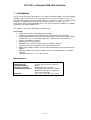
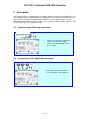
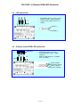
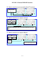
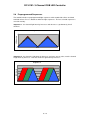
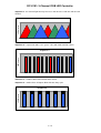
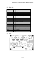
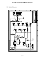
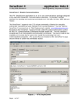
DIY K191
User manual
CONTENTS
1 INTRODUCTION.......................................................................... 2
2 DESCRIPTION............................................................................. 3
2.1
Common anode LED strip connection. ........................................................3
2.2
Incandescent light bulb connection. .............................................................3
2.3
LED connection............................................................................................4
2.4
Common anode RGB LED connection. .......................................................4
2.5
Module connection to a microcontroller (Serial TTL interface). ....................5
2.6
Module connection to a computer serial port. ..............................................5
2.7
Module connection to a computer USB port.................................................5
2.8
Preprogrammed Sequences. .......................................................................6
3 COMMANDS................................................................................ 8
3.1
Command Format. .......................................................................................8
3.2
Command Description..................................................................................8
4 WINDOWS SOFTWARE. ........................................................... 10
4.1
Interface description...................................................................................10
4.2
Module control from Microsoft Visual Basic. ..............................................12
5 KIT ASSEMBLY. ........................................................................ 12
5.1
Parts List. ...................................................................................................14
5.2
PCB............................................................................................................14
5.3
Module Schematic. ....................................................................................15
DIY K191: 3-Channel RGB LED Controller
1 Introduction.
This kit has been designed to function as a versatile LED control module. The LED controller
provides 3 high current channels to create light effects for the presentations, parties, etc.
The module includes preprogrammed light sequences and can be used as a standalone LED
controller. The module also supports a serial interface which uses only 2 wires to
communicate with your microcontroller or PC. The simple command set allows easy module
control from the microcontroller or PC.
The module is ideal for use with flexible LED light strips.
Key Features
• 3 high current channels with independent control.
• Suitable for common anode RGB LED strips, LEDs and incandescent bulbs.
• 6 preprogrammed light sequences with hard transition effects (running light, Strobo,
random colors, etc…) and smooth fade effects (color change, slow on/off, etc...).
• Custom user-editable sequence.
• Wide-range effect speed adjust.
• Memory for last selected sequence and user-editable sequence.
• Serial TTL interface to control from your microcontroller or PC.
• Addressable. Multiple modules can be connected with independent control for each
module.
• Windows software to control the module from PC and download the user-editable
sequence.
• Small form factor (2.2” x 1.55”, 56 x 39 mm).
Specifications
Operating Voltage
Channel Current
LED PWM frequency
LED intensity control
Communication Interface
Dimension
12VDC (nominal)
5A max, 12A max for all 3 channels
480 Hz
250 intensity levels/channel
Serial RS232 and serial TTL interface,
9600 baud, 8 data bits, 1 stop bit, no
parity, no handshaking
2.2” x 1.55” x 0.5”, 56 x 39 x 12 mm
2 / 15
DIY K191: 3-Channel RGB LED Controller
2 Description.
The module includes a microcontroller, 5V voltage regulator and high current MOSFETs. The
microcontroller provides PWM control for the MOSFETs, the serial communication interface
and includes 6 preprogrammed light effect sequences. Custom light sequences can be
downloaded to the microcontroller memory. Press a button to switch the light sequences. The
last selected sequence is saved in memory.
2.1
Common anode LED strip connection.
12V
Connect the common anode to the
+ of the 12VDC power supply.
Connect the color cathodes to the
R-, G-, and B-.
•
•
2.2
Incandescent (12V) light bulb connection.
12V
•
Connect the bulbs to the outputs
R, G, B (polarity is not important).
3 / 15
DIY K191: 3-Channel RGB LED Controller
2.3
LED connection.
•
12V
•
Each LED requires a series current
limiting resistor – 680R supplied
Connect LED anode to th R+, G+,
and B+.
Anode (+)
Cathode (-)
2.4
Common anode RGB LED connection.
RGB LED
1
12V
910 Ω
•
2 3 4
•
RGB LEDs require 3 x series
current limiting resistors – 680R
supplied.
Connect LED anode to +, cathodes
to R-, G- and B- .
4-Red cathode
3-Common anode
2-Blue cathode
1-Green cathode
4 / 15
DIY K191: 3-Channel RGB LED Controller
2.5
Module connection to a microcontroller (Serial TTL interface).
Microcontroller
GND
2.6
TX
Module connection to a computer serial port.
PC
USB
PORT
Serial
PORT
Use a Serial straight-through cable to connect LED controller to PC. The cable
should have a male DB9 connector at one end and a female DB9 connector at the
other.
2.7
Module connection to a computer USB port.
PC
USB
PORT
Serial
PORT
USB to
Serial TTL
Converter
Use USB to Serial Port Converter
to connect LED controller to PC
5 / 15
DIY K191: 3-Channel RGB LED Controller
2.8
Preprogrammed Sequences.
The module includes 6 preprogrammed light sequences with smooth fade effects and hard
transition effects. Press a button to switch the light sequences. The last selected sequence is
saved in memory.
Sequence 1 - the channel light intensity increases and decreases synchronously for all
channels.
LED Intensity
Sequence 1
Tim e
Sequence 2 - the channel 1 light intensity increases and stays at max value, next the channel
2 light intensity increases. Then the channel 3 light intensity increases.
LED Intensity
Sequence 2
Tim e
6 / 15
DIY K191: 3-Channel RGB LED Controller
Sequence 3 - the channel light intensity increases and decreases with the shift for each
channel.
LED Intensity
Sequence 3
Tim e
Sequence 4 – sequenced colors: red – green – blue with hard transition effects.
LED Intensity
Sequence 4
Tim e
Sequence 5 – random colors with hard transition effects.
Sequence 6 – strobe effect: all outputs blink with 50% duty cycle.
LED INtensity
Sequence 6
Tim e
7 / 15
DIY K191: 3-Channel RGB LED Controller
3 Commands.
3.1
Command Format.
The module is controlled using a simple command set. The character decimal 254 (0xFE) is a
command prefix. All commands start with 0xFE and a device address byte. Then a one
command code byte followed by the parameters.
Command Syntax: 0xFE [device address byte] [command byte] [parameter]
Command Summary
Prefix Command
0xFE
0x41
0xFE
0x42
0xFE
0x43
0xFE
0x4C
0xFE
0x52
0xFE
0x54
3.2
Parameter
1 byte
2 bytes
1 byte
61 bytes
1 byte
1 byte
Description
Set the module address
Set the channel intensity level
Start Sequence
Download the custom sequence
Set the intensity level for all channels
Set sequence time
Command Description.
Set the module address
Syntax hexadecimal 0xFE [device address] 0x41 [new address]
Parameter
Length
Description
[new address]
1 byte
New module address
Description: This command sets the module address. The address range is 0x4C – 0x5A.
Default module address is 0x4C. The address 0x00 is a common address for all modules.
The module address is stored in internal module EEPROM.
The address change requires 50 ms to take effect; therefore, the subsequent input must
have an appropriate delay.
Command Example:
0xFE 0x4C 0x41 0x52 – for module with address 0x4C set the new address 0x52.
Set the channel intensity level
Syntax hexadecimal 0xFE [device address] 0x42 [channel number] [intensity level]
Parameter
Length
Description
[channel number]
[intensity level]
1 byte
1 byte
Channel number (1,2 or 3)
Intensity level (from 0 to 250)
Description: This command sets the channel intensity level.
Command Example:
0xFE 0x4C 0x42 0x02 0x82 – for module with address 0x4C set for the channel 2 the
intensity level 0x82.
8 / 15
DIY K191: 3-Channel RGB LED Controller
Start Sequence
Syntax hexadecimal 0xFE [device address] 0x43 [sequence number]
Parameter
Length
Description
[sequence number]
1 byte
Sequence number
Description: Start the preprogrammed light sequence. The sequence range is from 1 to 7
(1 – 6 preprogrammed sequences, 7 – custom user-editable sequence).
Command Example:
0xFE 0x4C 0x43 0x04 – for module with address 0x4C start the sequence with number
0x04.
Download the custom sequence
Syntax hexadecimal 0xFE [device address] 0x4C [sequence time] [intensity data for
channel 1, channel 2 and channel 3]
Parameter
Length
Description
[sequence time]
[intensity data]
1 byte
60 bytes
Sequence time (from 0 to 250)
Intensity data for the channel 1 (bytes from 1 to 20),
channel 2 (bytes from 21 to 40) and channel 3 (bytes
from 41 to 60)
Description: Download the custom user-editable sequence to module memory.
The download process requires 100 ms to take effect; therefore, the subsequent input
must have an appropriate delay.
Command Example:
0xFE 0x4C 0x4C 0x20 <data byte 1> … < data byte 60> – for module with address
0x4C download the custom sequence with sequence time 0x20.
Set the intensity level for all channels
Syntax hexadecimal 0xFE [device address] 0x52 [intensity level]
Parameter
Length
Description
[intensity level]
1 byte
Intensity level (from 0 to 250)
Description: This command sets the intensity level for all channels.
Command Example:
0xFE 0x4C 0x52 0x82 – for module with address 0x4C set the intensity level 0x82 for all
channels.
Set sequence time
Syntax hexadecimal 0xFE [device address] 0x54 [sequence time]
Parameter
Length
Description
[sequence time]
1 byte
Sequence time (from 0 to 250)
Description: Set sequence time for the current sequence.
Command Example:
0xFE 0x4C 0x54 0x40 – for module with address 0x4C set time 0x40 for the current
sequence.
9 / 15
DIY K191: 3-Channel RGB LED Controller
4 Windows software.
The Windows software provides module control from PC and and is used to create custom
user-editable sequences. Use a USB to Serial Converter or Serial straight-through 9–way
cable to connect the LED controller to a PC.
The Windows software can be downloaded from “www.kitsrus.com/zip/k191.zip”
If you use the USB to Serial Converter:
1. Install the Virtual Com Port Drivers. If you use the USB converter with FTDI FT232
chip the drivers are available directly from FTDI website (www.ftdichip.com). The
drivers appear to the PC as an extra Com Port. Application software accesses the
USB device in the same way as it would access a standard Windows Com Port. The
serial data format is: one start bit, 8 data bits, and one stop bit. The baud rate is 9600
baud.
2. Connect the converter to computer USB port. To see which COM port has been
assigned to module, right click on “My Computer” desktop icon and select the “Device
Manager” tab. Now scroll down and open the “Ports (COM & LPT)” tab. You should
see the USB serial port string with port number (Fig.1).
Fig.1
No installation required. Copy the LEDControl.exe and IniDat.ini
files on your disk and double-click on LEDControl.exe to run the
program.
4.1
Interface description.
The program graphical interface
includes the 3 sections:
1. LED Control
2. Custom Light Sequence
3. Board Setup
LED Control section includes
the tools to set the light intensity
for the each channel. When you
move the slide bar the program
send the commands to set the
channel intensity level. Also, you
can select and start the
preprogrammed sequence and
set sequence time.
10 / 15
DIY K191: 3-Channel RGB LED Controller
Custom Light Sequence section provides the tools to create the custom sequence. The
section includes a table with the 3 columns. The first column includes the intensity data for the
channel 1, the second column – for the channel 2 and last column – for the channel 3. The
each column includes 20 points (cells) to hold channel intensity data.
To create the custom sequence enter data in cells (like in Excel Spreadsheet). Move the slide
bar to set the step time between points and click “Download to Board” button. The program
will send custom sequence data to board and start the custom sequence automatically.
Click “Save to file” button to save custom sequence data. The program will open the Save
Dialog form. Enter the file name and click OK button to save data in file.
You can also read custom sequence data from the file. Click “Open Data File” button and
select the file. The program will read data and fill the table cells automatically.
Board Setup section provides the tools to select the virtual serial port, display the board
connection status and set the board address.
If you run the program first time select the Virtual Serial Port number and click CONNECT
button. Check the board connection with the board status indicator.
The board address provides the opportunity to connect the multiple boards with the
independent control for each board. The address range is 0x4C – 0x5A. Default module
address is 0x4C. The address 0x00 is a common address for all modules. The module
address is stored in internal module EEPROM.
To set the board address select the address from drop-down box and click Set Address
button. The program will send a command to set the board address.
11 / 15
DIY K191: 3-Channel RGB LED Controller
4.2
Module control from Microsoft Visual Basic.
Visual Basic is one of the easiest languages to use for serial port communications. The
mscomm32.ocx driver controls all the serial port communications and it's included with Visual
Basic. The example shows how you can control the RGB module using this serial port com
driver.
Option Explicit
Private Sub Port_Init()
With MSComm1
.CommPort = 2
‘set the active serial port
.Settings = “9600,N,8,1” ‘set the baud rate, parity, data bits, stop bits
.PortOpen = True
‘open the serial port
End With ‘MSComm1
End Sub
Private Sub Module_Control()
With MSComm1
If .PortOpen = False Then
.PortOpen = True
End If
‘ for module wth address 0x4C set for the channel 2 the intensity level 0x82
.Output = Chr$(&HFE) + Chr$(&H4C) + Chr$(&H02) + Chr$(&H82)
End With ‘MSComm1
End Sub
5 Kit Assembly.
Before starting, check the components supplied in the kit against the parts list.
It is recommended that components be soldered in following order:
1. Resistors R1 … R7.
2. Diodes D1 and D2.
Match up the bar on the diode D1 with the diode image on the
overlay.
3.
4.
5.
6.
7.
Capacitors C1, C3 (polarity is not impotent).
U1 socket.
78L05 voltage regulator.
Transistor Q4.
Capacitor C2.
C2 – Electrolytic capacitor is polarized. The positive lead is market on the
overlay, the negative is marked on the body of the capacitor.
8. Tactile switch.
9. LED.
10. MOSFETs.
12 / 15
DIY K191: 3-Channel RGB LED Controller
Insert MOSFETs
in this direction
11. Power and LEDs connectors.
12. Header J2.
13. DB9 connector.
Pre-test. Do not insert the microcontroller chip into socket yet. Connect a 12VDC supply to
power connector and measure the voltage across pin V and ground pin of the serial interface
connector J1. If this voltage is approximately 5 volts, remove power and insert the
microcontroller chip U1.
Three LEDs, 1 x red, 1 x green and 1 x blue, together with 3 x 680R current limiting resistors
have been included with the kit. These components can be connected to the controller for
testing. The microcontroller chip includes a test program that flashes each LED in turn.
First connect all the LEDs and resistors to module according to Fig 2.3. Connect the power
supply and turn on – each LED will flash in turn.
•
•
Newer short the module outputs.
Do not connect LEDs if power supply is connected to module.
13 / 15
DIY K191: 3-Channel RGB LED Controller
5.1
Parts List.
Ref Des
Capacitors
C1
C2
C3
Resistors
R1, R2, R3, R7
R4, R5
R6
Resistors for
testing
Semiconductors
D1, D2
U1
U2
Q1, Q2, Q3
Q4
Miscellaneous
IC socket, 8 pin
PWR,R,G,B
J1
J2
PWR JACK
SW1
LED1
LEDs for testing
5.2
Qty
Type
1
1
1
0.33uF ceramic
10uF 16V electrolytic
0.1uF ceramic
4
2
1
3
470R 0.25W carbon film
5.1K 0.25W carbon film
10K 0.25W carbon film
680R 0.25W carbon film
2
1
1
3
1
1N4148 diode
CY8C24124A-24PXI MCU
78L05, 5V regulator
FDU8782 n-channel MOSFET
2N3904 transistor
1
4
1
1
1
1
1
3
Socket for U1
Terminal block, 2 pin, 5.08mm step
DB9 female connector
Header 2 pin
Power jack, 2.5mm central positive pin
Tactile switch
LED 5mm
5mm - 1 x Red, 1 x Green, 1 x Blue
PCB.
14 / 15
DIY K191: 3-Channel RGB LED Controller
5.3
Module Schematic.
15 / 15