1
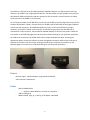
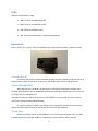
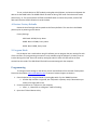
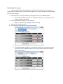
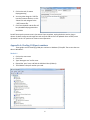
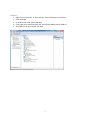
SE-001
Serial Extender
User Guide
F966
Rev. 20120821
Customer Service Department
www.coloradotime.com
Email: [email protected]
Phone: 970-667-1000, x256
Toll Free U.S. /Canada 800-287-0653, x256
Fax: 970-667-1032
Colorado Time Systems
Corporate Office
1551 East 11th Street
Loveland, CO 80537 USA
Sales : 1-800-279-0111 x 250 or +1 970-667-1000 x 250
Service: 1-800-287-0653 x256 or +1 970-667-1000 x256
Service Fax: 970-667-1032
Web: www.coloradotime.com
Email: [email protected]
Information in this manual is subject to change without notice. Pictures and illustrations may not
accurately depict your version. Please check our website for the most current information; our user
manuals are available online in the customer service section of our website.
F966 Rev. 20120821
©2012 Colorado Time Systems. All rights reserved.
SE-001 Product User Manual
Contents
SE-001 ......................................................................................................................................................... 1
Power: ........................................................................................................................................................... 1
Ports: ............................................................................................................................................................. 1
LEDs: .............................................................................................................................................................. 2
Dip Switch: .................................................................................................................................................... 2
1: Device A or B ......................................................................................................................................... 2
2: Link USB and RS232............................................................................................................................... 2
3: Link Test ................................................................................................................................................ 2
4: Restore Factory Defaults....................................................................................................................... 3
5: Program Mode ...................................................................................................................................... 3
Programming ................................................................................................................................................ 3
Uploading Firmware...................................................................................................................................... 5
Appendix A: Finding COM port numbers ...................................................................................................... 6
Windows 7/Vista/XP ................................................................................................................................. 6
Method 1............................................................................................................................................... 6
Method 2............................................................................................................................................... 7
The SE-001 is a device that can be used to extend a standard COM port or a USB serial port over long
distances, up to 4000’, over a high speed RS-485 link. The device does not alter the data in any way, but
does allow for different baud rates and port settings for each connection. It also functions as a USB to
Serial converter if the RS485 is not connected.
As a serial port extender, the SE-001 works in pairs. Set one SE-001 to Device A (dip switch 1 up) and one
to Device B (dip switch 1 down). Connect the pair of SE-001s with an RJ45 cable of the length needed to
connect the two computers, up to 4000 feet (1220 m). Finally, connect each SE-001 to its target
computer, using either a USB or 9-pin serial port. The SE-001 can get power from the USB port; if
connected to a 9-pin serial port, use the external USB wall adapter to connect to AC power. Follow the
instructions on the following pages to set up the ports and baud settings for your particular application.
As a USB to serial converter, the SE-001 works alone. Simply set dipswitch 2 down, and using the
appropriate cables, connect the USB port to meet management computer and the 9-pin serial port to
COM1 on the System 6. Do not connect anything to the RJ 45 port. Follow the instructions on the
following pages to set up the ports and baud settings for your particular application.
Power:
External supply: USB wall adapter using standard USB cable
USB Connection: 500mA max
Ports:
-
RS232 via DB9 female
o Requires a NULL Modem to connect to a computer
USB via USB type B
RS485 via RJ45, using TP_C and TP_D, full duplex, switchable
1
LEDs:
LEDs are numbered left to right.
1. RS485: Flashes on RS485 data traffic
2. RS232: Flashes on RS232 data traffic
3. USB: Flashes on USB data traffic
4. CPU: Flashes when powered on and operating normally
Dip Switch:
Down is active, up is inactive. They are numbered left to right, and the number is under the switch.
1: Device A or B
Implements the correct crossover between the devices that are linked. One device must be A
and one must be B for the crossover to be correct. Set the dip switch up for A and down for B.
2: Link USB and RS232
When dip switch 2 is set down, any data sent on USB will be transmitted via RS232. Data
received on RS232 will be sent on USB. RS232 and USB are intended for SHORT runs only, less than 25’.
For longer runs, use the RS485 link.
This makes the device a USB to Serial converter if the RS485 is not connected. This can be used to
connect the System6 COM1 to Meet Manager.
** If active, the device creates a star network of all 3 interfaces. Everyone will receive every
packet, and every packet sent will be transmitted over the other two interfaces.
3: Link Test
Sends out a beacon packet via the RS485 port. This will transmit one packet every .5s, and is
intended to help test the longer RS485 run. This does not test the RS232 or USB in any way.
2
To use, set both devices to TEST mode by setting dip switch 3 down, and connect and power the
devices via the RS485 cable. The RS485 LED will be solid on during TEST mode. Each device will send a
packet every .5s. The receive device will flash the USB LED when it receives the packet, and the TEST
device will flash the RS232 LED when it sends the data.
4: Restore Factory Defaults
Resets the interface high and low speeds to the factory defaults. This must be in the DOWN
position prior to powering on the device.
Factory Settings:
USB: Baud: 115200, Parity: None
RS485: Baud: 1.55Mbs, Parity: None
RS232: Baud: 19200, Parity: None
5: Program Mode
Put the device into a mode where using PC software you can program the port settings for each
of the interfaces. The programming connection is only available using the USB port. All other ports are
inactive during this mode. Enter this mode by setting dip switch 5 down. All LEDs will be on when
entered into this mode. The USB LED will flash while communicating with the computer.
Programming
To change internal settings on the device, you will need software from Colorado Time Systems.
Please see the website: www.coloradotime.com or contact Customer Support to obtain it.
1. Place the device into ‘Program Mode’ by moving dip switch 5 to the ‘DOWN’ position.
a. All other dip switches are ignored, but if dip switch 4 (factory reset) is down when you
reboot, all changes will be lost
2. Connect the device to a USB port on the computer
a. LEDs 1, 2, 3 should be on solid green. 4 will be flashing.
3. Open the CTS Serial Device Utility
3
4. From the Device drop down box, select ‘Serial Extender’.
a. Select the correct COM port.
b. The Attached Product should fill in automatically if detected. If not, please check that
you have the correct COM port. Notice the Firmware version, and the Current Baud
Rates have all filled in.
5. You may now change the settings to any combination you wish. Set all of the settings to what
you want them to be.
a. Warning: Most computers do not support baud rates above 115,200kbps.
6. Click the ‘Save New Settings’ button and the settings are sent to the device.
a. The ‘Current Baud
Rate’ will update
with what is read
back from the device
7. Move dip switch 5 to the up
position before unplugging
the device. Changes are not
saved until you exit program
mode.
4
Uploading Firmware
You will need a Firmware file, available only from Colorado Time Systems. If you are having
problems with this device, please contact Customer Support first. They will provide you with the update
if they deem it necessary.
1. Place the device into ‘Program Mode’ by moving dip switch 5 to the ‘DOWN’ position.
a. All other dip switches are ignored, but if dip switch 4 (factory reset) is down when you
reboot, all changes will be lost
2. Connect the device to a USB port on the computer
a. LEDs 1, 2, 3 should be on solid green. 4 will be flashing.
3. Open the CTS Serial Device Utility
4. From the Device drop down box, select ‘Serial Extender’.
a. Select the correct COM port.
b. The Attached Product should fill in automatically if detected. If not, please check that
you have the correct COM port. Notice the Firmware version, and the Current Baud
Rates have all filled in.
5
5. Click on the tab, Firmware
Reprogramming
6. You may either drag the *.SEF file
into the Firmware file box, or click
‘Select File’ and navigate to the
*.SEF firmware file.
7. Click ‘Start Upload’ and the file will
be uploaded and programmed to
the SE-001.
Do NOT interrupt the process once it has started. Once complete, unplug the device and re-plug to
reboot. Go back to steps one through four and verify the FW version has updated. Once verified, move
dip switch 5 to the ‘UP’ position to resume normal operation.
Appendix A: Finding COM port numbers
These guides are for identifying COM port numbers in Windows 7/Vista/XP. The screen shots are
done in Windows 7.
Method 1
1. Click on the start menu
2. Click ‘Run’
3. Type ‘devmgmt.msc’ and hit enter
4. Expand the ‘ports’ tree, and find the USB Serial Port (COM xx).
5. The COM XX is the port number you need.
6
Method 2
1. Right-Click on ‘Computer’ or ‘My Computer’ from the desktop or start menu
2. Select ‘Manage’
3. In the left Pane, select ‘Device Manager’.
4. In the right pane, expand the Port tree, and find the USB Serial Port (COM xx).
5. The COM xx is the port number you need.
7