1
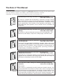
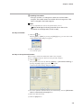
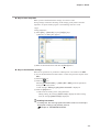
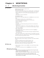
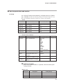
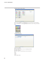
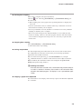
No. CP-UM-5458E
SLP-C45
Smart Loader Package
for the
SDC45/46
Digital Indicating Controller
User's Manual
Thank you for purchasing the SLP-C45
Smart Loader Package for SDC45/46 .
This manual contains information for
ensuring correct use of the SLP-C45. It
also provides necessary information for
installation, maintenance, and troubleshooting.
This manual should be read by those
who design and maintain devices that
use the SDC45/46 and SLP-C45.
Be sure to keep this manual nearby for
handy reference.
RESTRICTIONS ON USE
This product has been designed, developed and manufactured for general-purpose
application in machinery and equipment.
Accordingly, when used in applications outlined below, special care should be taken to
implement a fail-safe and/or redundant design concept as well as a periodic
maintenance program.
• Safety devices for plant worker protection
• Start/stop control devices for transportation and material handling machines
• Aeronautical/aerospace machines
• Control devices for nuclear reactors
Never use this product in applications where human safety may be put at risk.
IMPORTANT
Do not apply too much force when connecting the loader plug. Doing so
might damage the instrument.
Handling Precautions
Application of excessive force to the loader plug might cause
communications failure. If this happens, reconnect the loader plug
correctly.
NOTICE
Be sure that the user receives this manual before the product is used.
Copying or duplicating this user’s manual in part or in whole is forbidden. The information and specifications in this manual are subject to
change without notice.
Considerable effort has been made to ensure that this manual is free
from inaccuracies and omissions. If you should find an error or omission, please contact Yamatake Corporation.
In no event is Yamatake Corporation liable to anyone for any indirect,
special or consequential damages as a result of using this product.
©2008 Yamatake Corporation ALL RIGHTS RESERVED
Conventions Used in the Manual
The following conventions are used in this manual:
Handling Precautions :
Handling Precautions indicate items that the user should pay attention to
when handling the SLP-C45.
Note
Notes indicate useful information that the user might benefit by knowing.
This indicates the item or page that the user is requested to refer to.
(1), (2), (3)
Numbers within parentheses indicate steps in a sequence or indicate
corresponding parts in an explanation.
[OK] button
Indicates a selection button in screens displayed on the personal
computer.
[Option]
Indicates messages and menus displayed on the personal computer.
>>
Indicates the result of an operation, details displayed on the personal
computer or devices, or the state of a device after an operation.
[Ctrl] key, [a] key
Indicates keys on the keyboard.
[Ctrl]+[a] keys
Indicates the operation of pressing the [a] key while the [Ctrl] key is held
down.
Unpacking
Check the following items when removing the SLP-C45 from its package:
1. Check the model No. to make sure that you have received the product that you ordered.
2. Check the SLP-C45 for any apparent physical damage.
3. Check the contents of the package against the packing list to make sure that all accessories are included
in the package.
After unpacking, handle the SLP-C45 and its accessories taking care to prevent damage or loss of parts.
If an inconsistency is found or the package contents are not in order, contact your dealer immediately.
Name
Model No.
SLP-C45 System disc
SLP-C45J60
USB loader cable
User's Manual
i
Qty
1
-
1
CP-UM-5458E
1
Remarks
CD-ROM.
In addition to the SLP-C45
program, this CD contains the
SLP-C35 engineering tool for
the SDC15/25/26/35/36.
This manual.
The Role of This Manual
A total of five different manuals are available for the SDC45/46. Read them as necessary for your specific requirements. If a manual you require is not available, contact Yamatake Corporation or its dealer.
Additionally, you can download necessary manuals from "http://www.yamatake.com".
C P-U
User's
3E
M-012
l
Manua
G
WARNIN
N
CAUTIO
WARN
CAU TI
SDC45/46 Digital Indicating Controller Installation Instructions
Manual No. CP-UM-5445E
ING
ON
This manual is supplied with the SDC45/46. Personnel in charge of design
and/or manufacture of a system using the SDC45/46 must thoroughly read this
manual. This manual describes the safety precautions, installation, wiring,
primary specifications, and transitions of key operations and displays. For
further information about operation, refer to another manual, Installation and
Configuration.
SDC45/46 Digital Indicating Controller User's Manual for Displays and
Settings
Manual No. CP-SP-1265E
The manual is a reference document necessary to set or change data. The
manual lists up the displays, setup items, setting ranges, and initial values.
SDC45A/46A Digital Indicating Controller User's Manual for Installation
and Configuration
Manual No. CP-SP-1218E
Personnel in charge of design, manufacture, operation, and/or maintenance
of a system using SDC45/46 must thoroughly read this manual. This manual
also describes the installation, wiring, connections for communication, all
functions and settings of the SDC45/46, operating procedures,
troubleshooting, and detailed specifications.
SDC45V/46V Digital Indicating Controller User's Manual for
Computational Functions
Manual No. CP-SP-1275E
It describes the computation functions of the SDC45V/46V. Please read it
together with the Installation and Configuration manual (CP-SP-1218E) and
the Displays and Settings manual (CP-SP-1265E).
SLP-C45 Smart Loader Package for the SDC45/46 Digital Indicating
Controller
Manual No. CP-UM-5458E
This manual.
This manual is supplied with the SLP-C45 Smart Loader Package. The
manual describes the software used to make various settings for the
SDC45/46 using a personal computer. Personnel in charge of design or setting of a system using SDC45/46 must thoroughly read this manual. The
manual describes installation of the software into a personal computer, operation of the personal computer, various functions, and setup procedures.
ii
Organization of the Manual
This manual is organized as follows:
Chapter 1. INTRODUCTION
Be sure to read this chapter before you start using the Smart Loader Package.
This chapter describes the required operating environment for the personal
computer, tells how to install the package, and briefly introduces its features.
Chapter 2. STARTING AND QUITTING THE LOADER
This chapter describes how to start and quit the loader.
Chapter 3. SETUP
This chapter describes how to set up the data.
Chapter 4. MONITORING
This chapter describes how to change the settings, as well as the screens
monitoring the operation status.
Chapter 5. TROUBLESHOOTING
This chapter describes error messages that are displayed when a problem occurs,
and tells how to remedy the problem.
iii
Contents
Conventions Used in the Manual
Unpacking
The Role of This Manual
Organization of the Manual
Chapter 1.
INTRODUCTION
1-1 Overview • • • • • • • • • • • • • • • • • • • • • • • • • • • • • • • • • • • • • • • • • • • • • • • • • • • • • • • • • • • • • • • • • • • 1-1
■ Loader functions • • • • • • • • • • • • • • • • • • • • • • • • • • • • • • • • • • • • • • • • • • • • • • • • • • • • • • • 1-1
1-2 System Requirements • • • • • • • • • • • • • • • • • • • • • • • • • • • • • • • • • • • • • • • • • • • • • • • • • • • • • 1-2
■ Hardware • • • • • • • • • • • • • • • • • • • • • • • • • • • • • • • • • • • • • • • • • • • • • • • • • • • • • • • • • • • • • • • 1-2
■ Hardware configuration • • • • • • • • • • • • • • • • • • • • • • • • • • • • • • • • • • • • • • • • • • • • • • • • 1-3
1-3 Installing the Loader • • • • • • • • • • • • • • • • • • • • • • • • • • • • • • • • • • • • • • • • • • • • • • • • • • • • • • • 1-4
1-4 Installing the USB Loader Cable Device Driver • • • • • • • • • • • • • • • • • • • • • • • • • • • • 1-9
■ Installing the device driver • • • • • • • • • • • • • • • • • • • • • • • • • • • • • • • • • • • • • • • • • • • • • 1-9
■ Uninstalling the device driver • • • • • • • • • • • • • • • • • • • • • • • • • • • • • • • • • • • • • • • • • 1-15
Chapter 2.
STARTING AND QUITTING THE LOADER
■ Starting the loader • • • • • • • • • • • • • • • • • • • • • • • • • • • • • • • • • • • • • • • • • • • • • • • • • • • • • 2-1
■ Quitting the loader • • • • • • • • • • • • • • • • • • • • • • • • • • • • • • • • • • • • • • • • • • • • • • • • • • • • • 2-1
Chapter 3.
SETUP
3-1 Setup Function • • • • • • • • • • • • • • • • • • • • • • • • • • • • • • • • • • • • • • • • • • • • • • • • • • • • • • • • • • • • 3-1
■ Overview • • • • • • • • • • • • • • • • • • • • • • • • • • • • • • • • • • • • • • • • • • • • • • • • • • • • • • • • • • • • • • • 3-1
■ Screen explanations • • • • • • • • • • • • • • • • • • • • • • • • • • • • • • • • • • • • • • • • • • • • • • • • • • • 3-1
3-2 Method of Setup • • • • • • • • • • • • • • • • • • • • • • • • • • • • • • • • • • • • • • • • • • • • • • • • • • • • • • • • • • • 3-4
Chapter 4.
MONITORING
4-1 Monitoring Function • • • • • • • • • • • • • • • • • • • • • • • • • • • • • • • • • • • • • • • • • • • • • • • • • • • • • • • 4-1
■ Overview • • • • • • • • • • • • • • • • • • • • • • • • • • • • • • • • • • • • • • • • • • • • • • • • • • • • • • • • • • • • • • • 4-1
■ Screen explanations • • • • • • • • • • • • • • • • • • • • • • • • • • • • • • • • • • • • • • • • • • • • • • • • • • • 4-2
4-2 Method of Operation • • • • • • • • • • • • • • • • • • • • • • • • • • • • • • • • • • • • • • • • • • • • • • • • • • • • • • • 4-5
■ How to operate the numeric monitor screen • • • • • • • • • • • • • • • • • • • • • • • • • • • 4-5
■ How to operate the trend monitor • • • • • • • • • • • • • • • • • • • • • • • • • • • • • • • • • • • • • • 4-7
Chapter 5.
TROUBLESHOOTING
5-1 Error Messages and Remedy • • • • • • • • • • • • • • • • • • • • • • • • • • • • • • • • • • • • • • • • • • • • • • 5-1
■ Setup error messages • • • • • • • • • • • • • • • • • • • • • • • • • • • • • • • • • • • • • • • • • • • • • • • • • 5-1
■ Communications error messages • • • • • • • • • • • • • • • • • • • • • • • • • • • • • • • • • • • • • • 5-1
■ File error messages • • • • • • • • • • • • • • • • • • • • • • • • • • • • • • • • • • • • • • • • • • • • • • • • • • • • 5-1
5-2 Other Troubleshooting• • • • • • • • • • • • • • • • • • • • • • • • • • • • • • • • • • • • • • • • • • • • • • • • • • • • • 5-2
iv
Chapter 1.
1 - 1
INTRODUCTION
Overview
The SLP-C45 (simply called "the SLP" from here on) is a software engineering tool for the SDC45/46 (simply
called "the SDC" from here on).
The SLP runs on Windows 2000 Professional/XP/Vista (simply called "Windows" from here on) on a personal
computer.
■ Loader functions
The SLP has the following functions:
• Setup
• Monitoring
• Adjustment
● Setup function
This function is for setting the required controller parameters on the personal
computer and writing (transferring) them to the controller.
● Monitoring function
After the setup parameters have been written to the controller, it is possible to
change and tune control constants while the controller is running, to switch modes
(RUN/READY, AUTO/MANUAL, etc.), and to check RUN status and alarm
occurrence.
The run state can also be checked on the Trend screen, and sampled data can be
output in CSV format so that it can be handled in third-party spreadsheet software
such as Microsoft Excel.
Handling Precautions
• The monitor target is limited to only one unit when monitoring is done
via the loader jack on the front panel.
● Adjustment function
This function is used when the user adjusts controller input.
For details on the adjustment function, refer to:
SDC45/46 Digital Indicationg Controller User's Manual for Installation
and Configuration (CP-SP-1218E).
Handling Precautions
• Our guarantee does not cover problems caused by incorrect settings
made by the customer. To reset the SDC to the factory default
settings during adjustment, select [Option] → [Initilize calibrate
parameter to factory value] from the pull-down menu. This will discard
the user's settings and restore the factory defaults. If this is
mistakenly done during adjustment, all user settings will be lost.
1-1
Chapter 1. INTRODUCTION
1 - 2
System Requirements
The following operating environment is required for using the SLP-C45:
■ Hardware
Item
Description
Personal Computer Target model
Memory
PC/AT compatibles with a Pentium chip or higher
(500 MHz or more)
32 MB or more
Operating system Windows2000 Professional/XP/Vista (32 bits)
USB Port
1 port or more
Serial Port
1 port or more (When use the CMC10L)
Peripheral Devices Display
1-2
1024 X 768 dot or more, 16 bit color or more
Hard disk drive
Hard disk with at least 40 MB of free space
CD-ROM drive
1 drive or more
Pointing device
Windows-compatible mouse or equivalent device
Chapter 1. INTRODUCTION
■ Hardware configuration
● General configuration
SDC45/46
SLP-C45
Communications
USB loader cable (accessory)
● Configuration with CMC10B/L
• When connecting up to 31 units
When connecting 31 or fewer SDC units, use the CMC10L communication
controller (sold separately).The CMC10L can convert data for interchange
between RS-232C and RS-485.
If the connected computer has a 3-wire RS-485 communications port, the
CMC10L is not necessary.
CMC10L
LOADER
11
12
13
14
15
CMC10
SDC45/46
Max. 31 units
• When connecting 32 units or more
When connecting 32 SDC units or more, use the CMC10L and multiple
CMC10B communication controllers (sold separately).
CMC10L CMC10B
LOADER
CMC10B
LOADER
12
13
14
14
15
RD
11
12
ERR
RD
14
power
SD
2
RD
SD
11
12
RD
13
14
ERR
15
ERR
15
RESET
CMC10
2 3 4
1
0
5
9
8 76
1
0
13
RESET
2 3 4
1
0
5
9
8 76
HOST CMC
B.RATE
SD
15
CMC10
SD
RD
CMC LOCAL
12
LOADER
power
2
CMC LOCAL
11
13
2 3 4
1
0
5
9
8 76
1
0
CMC LOCAL
SD
11
2 3 4
1
0
5
9
8 76
HOST CMC
B.RATE
HOST CMC
RD
CMC ADDRESS
SD
2
HOST CMC
B.RATE
HOST CMC
1
0
CMC ADDRESS
2 3 4
1
0
5
9
8 76
CMC10B
LOADER
power
HOST CMC
CMC ADDRESS
2 3 4
1
0
5
9
8 76
RESET
CMC10
CMC10
SDC45/46
Max. 31 units
Max. 31 units
Max. 31 units
Note
• Personal computers used for confirmation of hardware configuration.
Manufacturer
Model No.
Dell
PRECISION 380
IBM
ThinkPad A31
1-3
Chapter 1. INTRODUCTION
1 - 3
Installing the Loader
Install the SLP-C45 on the PC hard disk. Keep the installation CD as a backup.
This section describes how to install the SLP-C45 on a personal computer.
Handling Precautions
• The CD does not contain an operating system (OS), and cannot be used
on a PC that lacks an OS.
• If you start the installer while another application is running, the installer
may malfunction. Shut down other applications and then start the
installer. The SLP-C45 sometimes cannot be started due to a particular
combination of other applications and drivers.
For details on Windows and personal computer settings, refer to the
user’s manuals provided with Windows and with the personal computer.
• Windows 2000 Professional/XP Professional:
Only users belonging to the "Administrators" group can install/uninstall
this software.
Windows XP Home Edition:
Only users belonging to the computer "Administrators" group can
install/uninstall this software.
(1) Put the CD in the CD-ROM drive of your personal computer.
>> The following screen appears for installing the driver for the USB loader
cable and selecting a SLP model (SLP-C45 and SLP-C35).
(2) Click the [Install SLP-C45 for C45/46] button.
>> The following screen appears:
1-4
Chapter 1. INTRODUCTION
(3) Click the [Next >] button.
>> The following screen appears:
(4) If you agree to the software license agreement and wish to install the program,
click [Agree >]. To abort the installation, click [Don’t agree].
>> After clicking [Agree >], the following screen appears:
(5) Enter the user name and company name of a registered user, and then click the
[Next >] button.
>> The following screen appears:
1-5
Chapter 1. INTRODUCTION
(6) Click the [Next >] button
>> The following screen appears:
Note
• To change the installation destination directory, click [Browse...].
(7) Click the [Next >] button.
>> The following screen appears:
Note
• Check the necessary files.
To display a PDF file, it is necessary to install Adobe Reader.
For details, refer to:
Note on page 1-8.
(8) Check (put a check mark :
before) the software components you wish to
install and click the [Next >] button.
1-6
Chapter 1. INTRODUCTION
>> The following screen appears:
Note
• To change the start menu folder, enter the new folder name.
(9) Click the [Next >] button.
>> The following screen appears:
(10)Click the [Next >] button.
>> The following screen appears:
(11)Click the [Finish >] button.
>>When the installation is completed successfully, the screen will return to
the Windows screen.
1-7
Chapter 1. INTRODUCTION
Note
• Installation of Adobe Reader
If Adobe Reader is not installed on your personal computer, install it using
either of the following procedures:
• Download Adobe Reader from the Adobe Systems home page.
1-8
Chapter 1. INTRODUCTION
1 - 4
Installing the USB Loader Cable Device Driver
A device driver must be installed before using the USB loader cable.
Follow the procedure below to install the device driver.
■ Installing the device driver
Handling Precautions
• Be sure to follow the procedure below when installing the device driver.
The USB cable may not be recognized if the procedure is not followed. If
the cable is not recognized, uninstall the driver and then install it again.
• Administrator privileges on the computer are required for driver installation. Installation should be done by the administrator or by a user who
belongs to the administrator group. The USB loader cable is supported
on Windows 2000/XP/Vista (32 bit type). It is not supported on 64-bit
Windows XP, or on Windows 95, Windows NT, MS-DOS or PC-DOS.
• If there are multiple USB ports, connect the USB loader cable to the
same port every time. If it is connected to a different port, there is a
chance that driver installation may be required again.
1. Put the SLP CD-ROM into the CD-ROM drive of the personal computer.
>>The installation program is then started up automatically and the following
screen appears:
(1) Click the [Install USB loader cable driver] button.
>> The following screen appears:
1-9
Chapter 1. INTRODUCTION
(2) Click the [Next >] button.
>> The following screen appears:
(3) Select [AGREE] and click the [Next>] button.
>>The following screen appears :
1-10
Chapter 1. INTRODUCTION
(4) Click the [Continue Anyway] button.
>>The installation program then starts up, and after it is completed, the following screen appears:
(5) Click [Finish] button to complete the installation.
2. Insert the USB loader cable into the USB port.
>>When Windows recognizes the USB cable, the notification shown below
appears on the task tray and the driver installation wizard appears.
1-11
Chapter 1. INTRODUCTION
3. Install the device driver.
(1) Usually, when Windows recognizes the USB loader cable, the window shown
below appears. (In some cases, depending on the Windows environment, it may
not appear.) Select [No, not this time] and click the [Next >] button.
(2) For the retrieval location of the device driver to be installed, select the [No, not
this time] and click the [Next >] button.
>>Retrieval of the device driver starts.
1-12
Chapter 1. INTRODUCTION
>>When the device driver is found, the following window appears:
(3) Click [Continue Anyway].
>>Installation of the device driver starts
>>When the device driver installation is complete, the following window
appears:
1-13
Chapter 1. INTRODUCTION
(4) Click [Finish].
>>When the installation is complete, the notification shown below appears on
the task tray, and Windows now correctly recognizes the USB loader cable.
(5) Select [Control Panel] → [System] → [Hardware] → [Device Manager] (for
Windows XP/2000), and find the port number for the Yamatake USB Loader
Comm. from [Ports (COM & LPT)].
(6) Start the SLP, select [Menu] → [Option], and set to the communications port
number obtained in the previous step. Then press the [OK] button to complete
the configuration.
1-14
Chapter 1. INTRODUCTION
Note
• If the CD-ROM for the SLP is not available, execute drvsetup.exe on the
computer on which the SLP is installed. Then install the device driver.
Normally [C:\Program Files\slp\SLPC45].
■ Uninstalling the device driver
Handling Precautions
• Removing the driver requires restarting the computer. Close other
applications first, and then uninstall the driver.
• To uninstall the driver, administrator rights are required on the computer.
Uninstalling should be done by the administrator or by a user who
belongs to the administrator group.
1.
Execute the driver removal program.
(1) Go to [Control Panel] → [Add or Remove Programs] and click on
[Windows Driver Package - Yamatake (YC slp) USB (04/19/2007
1.0.0)]. Click the [Change/Remove] button.
(2) Click the [Yes] button.
(3) Restart the computer.
1-15
Chapter 2. STARTING AND QUITTING THE LOADER
Handling Precautions
• Before starting the Smart Loader, quit all other applications.
The program may not function if you start it while another application is
running. Set the power save setting, infrared communications and
screen saver to OFF.
• Make sure that the [Decimal symbol] has been set to " . " for [Control
Panel] → [Regional Settings] → [Number]. If it has been set to some
other character, the loader program cannot function correctly.
(Example: for Windows XP, go to [Control Panel] → [Date, Time,
Language, and Regional Options] → [Regional and Language Options]
→ [Regional Options] → [Customize...] → [Decimal symbol]. Select " . "
and click [OK] button. )
■ Starting the loader
Double-click the SLP-C45 (SDC45, 46)
icon on the desktop or click the
[Start] button at the lower left portion of the screen and select [Programs] →
[SLP] → [SLP-C45].
>>The SLP starts up and the menu window is displayed.
Note
• For operating system details and mouse setup, refer to the user’s manuals
provided with Windows.
■ Quitting the loader
Click the
icon at the top right of the screen, or selecting [Menu] → [Quit]
gives the same result.
2-1
Chapter 3.
3 - 1
SETUP
Setup Function
■ Overview
The setup function allows the user to set various parameters (required for
operation) and write these parameters to the SDC so that it functions according to
the user's particular control requirements. When the SDC is used for the first time,
it will not function as required unless it is set up by using this setup function.
Parameters such as SP (set point) and control constants (PID values) that are
changed relatively frequently while the SDC is running can also be set from the
Smart Loaders monitor function screen.
With the setup function, parameters that rare need changing once they are set are
saved to a file in list format before the SDC is started, and the saved file is called
up and written to the SDC in a single operation.
■ Screen explanations
● Menu screen
• Menu configuration list
Menu
Icon
Menu
Help
Submenu
Description
Shortcut Keys
Setup
Displays the Setup window.
[Ctrl]+[s]
Monitor
Displays the Monitor/Trend
window.
[Ctrl]+[m]
-
Calibration (J)
Displays the Adjustment window.
[Ctrl]+[ j ]
-
Option (E)
Changes the environment setup.
[Ctrl]+[e]
-
Quit
Quits the application.
[Ctrl]+[q]
-
Version (A)
Displays the version information.
[Ctrl]+[a]
3-1
Chapter 3. SETUP
● Setup screen
Toolbar
Menu bar
Selection
window
Message window
3-2
Parameter display area
Chapter 3. SETUP
● Menu configuration list
Menu
Icon
File
-
-
-
Edit
Display
-
Help
Description
Shortcut Keys
New
Creates new data.
[Ctrl]+[n]
Open
Opens existing data.
[Ctrl]+[o]
Save
Saves the active data.
[Ctrl]+[s]
Save As
Saves the active data with a
new name.
CSV Out (X) CSV Out (X) Saves the active data in CSV format.
CSV Out2 (Y)
CSV Out3 (Z)
HTML Out (H) HTML Out1 (H) Saves the active data in HTML format.
HTML Out2 (I)
HTML Out3 (J)
Prints out the data.
Print
(Same contents as data saved
in the HTML format.)
Recent File
Displays the recent file.
Quit
Quits the application.
Data Check
Checks all setting values.
Inputs to bit lists.
Bit edit
[Ctrl]+[a]
[Ctrl]+[x]
[Ctrl]+[h]
-
[Ctrl]+[q]
[Ctrl]+[d]
[Ctrl]+[b]
Input/Output
Port setup
Copy
Displays the input/output port
setup screen.
Makes a copy of the source.
[Ctrl]+[p]
Paste
Pastes the stored copy data.
[Ctrl]+[v]
-
Parameter disp area
-
Hint enable
Auto size
Size initalize
Cell size adjust
Graph
Computation unit
[Ctrl]+[r]
Writes the data to the device.
[Ctrl]+[w]
-
Read (SDC -> SLP)
(R)
Write (SLP -> SDC)
(W)
C45/46 Parameter initialize
Displays the parameter display
area.
Enables hint display.
Enables auto-cell size.
Initializes the cell size.
Matches cell size to the window.
Displays the graph.
Displays the computation unit.
(Only computation unit)
Reads the device's data.
-
Clock setup
-
Communication
Setup
Option
Submenu
-
[Ctrl]+[c]
-
Type Setting
Restore SDC45/46 parameters
to their factory settings.
Set the clock.
(Only computation unit)
Displays the varioua items.
Changes the type setup.
-
[Ctrl]+[t]
Environment Setting
Changes the environment setup.
[Ctrl]+[e]
Help
Displays the help.
-
[F1]
-
Information
Displays the handling precaution.
-
-
Version (A)
Displays the version information.
-
3-3
Chapter 3. SETUP
3 - 2
Method of Setup
Do setup offline (without connecting the USB loader cable to the SDC).
Click [Option] on the menu screen. Do the following setup tasks:
Step 1: Set the Smart Loader type
Step 2: Initialize (clear previous settings)
Step 3: Set up the environment
Step 4: Set up SDC parameters
Step 5: Save setup data
Step 6: Download the settings
Handling Precautions
• Steps 1 to 5 are required before the setup parameters are written to
the SDC. Be sure to perform these steps. Otherwise, the SDC may be
set up incorrectly. For example, the required setup items may not be
displayed or unneeded items may be displayed.
• Step 6: before the download, connect the controller to the computer
using the USB loader cable.
● Step 1. Set the Smart Loder type
Set the loader program type to match the SDC model number.
(1) Click the
icon.
Selecting [Option] → [Type Setting] or pressing the [Ctrl]+[t] keys gives the
same result.
>> The Type Setting dialog box is displayed.
(2) Set the mounting type, control output, input type, power voltage and additional
functions.
(3) Choose the desired selections for each item.
(4) Click the [OK] button.
3-4
Chapter 3. SETUP
Handling Precautions
• The type set here is a setting for the internal use of the loader
program. The model number of the SDC will not change even if the
type is changed in the loader program.
Note
• For an explanation of each of the specifications, refer to:
SDC45/46 Digital Indicating Controller User's Manual for
Installation and Configuration (CP-SP-1218E).
● Step 2. Initialize
(1) Click the
icon.
Selecting [File] → [New] or pressing the [Ctrl]+[n] keys gives the same result.
>>The Initialize Data dialog box appears.
(2) Click the [OK] button.
>> A new file opens.
● Step 3. Set up the environment
Before setting, connect the USB loader cable to the computer.
Set the communications port and font on the personal computer.
(1) Click the
icon.
The operation is the same by Selecting [Option] → [Environment Setting] or
pressing the [Ctrl] + [e] keys gives the same result.
>>The Environment Setting dialog box appears.
(2) To set the optimum communications port automatically, click the [USB loader
cable is automatically selected] button.
(3) Select the desired font size.
(4) Click the [OK] button.
3-5
Chapter 3. SETUP
Handling Precautions
• ÅE Normally, use the port that was selected after you clicked the
[USB loader cable is automatically selected] button.
Even if another communications port can be selected, it sometimes
cannot be used depending on its characteristics.
• Normally, select "Use Loader Cable."
● Step 4. Set up the SDC45/46 parameters
Set each of the parameters required for running the SDC.
Move the cursor to the target channel for each setup item, and do the following:
• When the setting is a numerical value
Enter the numerical value, and press the [Return] key.
• When the setting is selected by a number
Press the right mouse button (right-click) on a setup item. The list of settings
you can select will appear. Select a desired item to complete the setting.
Handling Precautions
• "– – – –” is displayed within the cell if setup of a parameter is not
required or is prohibited by previous settings. The parameter cannot
be set. If neccessary, re-check the type setting or other related
settings.
• About connection to the personal computer
Normally, the controller is connected to the personal computer with
the dedicated cable.
By selecting [Option] → [Environment Setting] and setting
[Communication Setup] to [Use CMC10L] or [Use CMC10B], the
controller can be connected through the CMC10B/L. In this case, the
environment setting and communication setup on the controller main
unit must be configured beforehand.
Configure the controller settings in the offline mode (with the cable not
connected to the controller).
Note
• For details on functions, refer to:
SDC45/46 Digital Indicating Controller User's Manual for
Installation and Configuration (CP-SP-1218E).
3-6
Chapter 3. SETUP
● Step 5. Save setup data
When you have finished with the settings, save them to a file.
Saving settings in advance and using saved settings greatly reduces the time
required to set up the loader program. The following items are saved:
• Type
• Setup parameters
(1) Select [File] → [Save As] or press [Ctrl]+[a] keys.
>>The Save As dialog box appears.
(2) Enter the desired file name and click the [Save] button.
● Step 6. Download the settings
Write the set parameters or parameters called up from a saved file to the SDC.
(1) Use the dedicated Smart Loader cable to connect the personal computer to the
SDC.
(2) Turn the SDC on.
(3) Click the
icon.
Selecting [Communication] → [Write (SLP→SDC)] from the pull-down
menu gives the same result.
>> The message "Writing is going to be executed" is displayed.
(4) Click the [OK] button.
>> This starts the writing of the setup parameters.
During writing, the message [Please wait] is displayed. When writing
ends, the message [Normal end] is displayed.
Handling Precautions
• If writing fails, the message [Communications error has occurred] is
displayed. If writing is not possible, refer to:
Chapter 5. TROUBLESHOOTING.
3-7
Chapter 4.
4 - 1
MONITORING
Monitoring Function
■ Overview
The SLP has the following two monitor screens:
• Numeric Monitor screen:
This screen is for performing operations such as changing settings or switching modes.
• Numeric display of the various RUN parameters (parameters can be changed)
• Indicator lamps for the various operation modes (lamp indications can be
operated)
• Alarm display (summary and detailed)
• Trend Monitor screen:
This screen is for monitoring the RUN status of the SDC in the form of a trend
graph.
• Screen display of trends for max. of sixteen data items
• Screen display of digital data trends for max. of five data items
• Export of sampled data as a CSV file *
• Trend screen saving
• Data type:
PV, SP, MV, user-defined data (all analog data that can be communicated)
• Sampling cycle:
250 ms, 500 ms, Variable from 1 to 3600 s (If the sampling cycle is 250 ms or
500 ms, the screen displays a max. of four data items and the display of digital
data trends is disabled.)
• Max. sampling number:
60,000 (5,000, 10,000, 30,000, or 60,000 can be selected in the [Setup] →
[Trend option] window).
If the sampling count exceeds the maximum, subsequent sampling data will be
saved in the next file.
* CSV (comma-separated value) is a data format that can be handled by third-party
spreadsheet software such as Microsoft Excel. With this format, sampled trend
data can be interpreted by spreadsheet software.
These screens can be used to perform the following operations:
• Monitoring of RUN status and changing of parameters on the Numeric Monitor
screen
• Switching of the RUN mode on the Numeric Monitor screen
• Tuning of control constants on the Numeric Monitor screen
• Monitoring of trends and sampling of data while the SDC is running
• Monitoring of alarm status on the Numeric Monitor screen
■ Before use
(1) Before starting to monitor, connect the SDC to the computer using the USB
loader cable.
(2) To display the monitoring screen, click [Monitor] in the menu window.
Handling Precautions
• When setting up or operating the monitoring function using the loader
program, connect the dedicated cable.
• Before starting the Trend Monitor, configure suitable monitoring settings.
• The sampling cycle sometimes shifts due to fluctuations in the
communications cycle. To perform measurement at exact times, use a
special recorder or data logger.
4-1
Chapter 4. MONITORING
■ Screen explanations
● Numeric monitor screen
• Menu configuration list
Menu
File
Icon
-
Submenu
Description
Quit
Quits the monitor window.
[Ctrl]+[q]
Numeric
Monitor (M)
Numeric Monitor
Start/Stop (M)
Starts/stops the monitor.
[Ctrl]+[m]
Option
(O)
Setup
Displays the Setup window.
-
Alarm (A)
Displays the Alarm Details window.
-
Command Line (C) Displays the Command Line
window.
4-2
Shortcut Keys
Trend
Monitor (T)
-
Help
-
Version (A)
-
Changes the display to the Trend
Monitor.
-
Displays the version information.
-
Chapter 4. MONITORING
● Trend monitor screen
• Menu configuration list
Menu
File
Icon
-
Trend
monitor
Option
Numeric
Monitor
-
Help
-
Submenu
Description
Shortcut Keys
Quit
Quits the monitor window.
[Ctrl]+[q]
Trend Monitor
Start/Stop (T)
Starts/stops the Trend Monitor
[Ctrl]+[t]
Clipboard Graph
Out
Outputs an image of the graph to
the windows Clipboard.
[Ctrl]+[c]
Setup
Displays the Setup window.
-
Changes the display to the
Numeric Monitor
-
Displays the version information.
-
Version (A)
4-3
Chapter 4. MONITORING
• Icon list
Icon
Description
Views the graph at the start time.
Views the graph segment 1/2 screen to the left.
Views the graph segment 1/4 screen to the left.
Views the graph segment 1/4 screen to the right.
Views the graph segment 1/2 screen to the right.
Views the graph at the latest time.
Zooms the graph out.
Undoes the graph zoom.
Zooms the graph in.
Specify a time scale for the graph.
1min.
2min.
10min.
1hr.
12hrs.
24hrs.
Auto
• Zooming the graph
Drag the mouse from the upper left portion to the lower right portion with the left
mouse button pressed.
• Canceling the zoomed graph
Drag the mouse from the lower right portion to the upper left portion with the left
mouse button kept pressed.
4-4
Chapter 4. MONITORING
4 - 2
Method of Operation
■ How to operate the numeric monitor screen
● Start of monitoring (start of communications)
The operation described below is required to start monitoring.
Otherwise, monitoring and rewriting of data cannot be performed.
• Click the
icon.
Selecting [Numeric Monitor] → [Numeric Monitor Start] gives the same result.
>> In normal operation:
The data on the SDC is displayed.
In case of an error:
The message [Check the device to which the
loader is connected] is displayed. Remedy
according to Chapter 5, TROUBLESHOOTING.
The following operations are possible when the device and the loader are correctly
connected:
● Monitoring of run state and changing of parameters
Numeric monitor (displayed Tag name
in table format)
Process Variable (PV)
Numeric group monitor
Set point (SP)
Manipulated variable (MV)
Status monitor (displayed
in lamp lighting status)
RUN/READY mode
AUTO/MANUAL mode
LOCAL/REMOTE status
Auto-tuning start/stop status
Self-tuning start/stop status
ALARM mode
Control output ON/OFF status
Event output ON/OFF status
Internal event ON/OFF status
DI terminal ON/OFF status
Operation (Changes in
numeric
values are limited to those
shown.)
SP value change
SP set change
MV change in MANUAL mode
PID value change
RUN↔READY change
AUTO↔MANUAL change
Auto-tuning start↔stop change
About the operation mode RUN/READY mode
0: RUN 1: READY
AUTO/MANUAL mode 0: AUTO 1: MANUAL
4-5
Chapter 4. MONITORING
● Changing of data
Enter the numerical value, and press the [Return] key.
● Setting of user-defined address
Optional data not in the table can be registered to user configuration address UF 1
to 8 in the table. Data can be read or written according to the data type.
• How to set user-defined address:
(1) Select the [Set monitor] tag under [Option (O)] → [Setup] in the pull-down
menu.
(2) Enter the address of the data to display according to SDC45/46 Digital
Indicating Controller User's Manual for Installation and Configuration
(CP-SP-1218E).
● Use of the command line
Data can be read or written or the mode switched by directly entering
communications commands on the command line.
Handling Precautions
• Transmission of the wrong command may result in problems for the
SDC. For this reason, take care when describing command types,
addresses, data and other information.
• For details on communications commands and data addresses,
refer to;
SDC45/46 Digital Indicating Controller User's Manual for
Installation and Configuration (CP-SP-1218E).
• Loader lock must be canceled.
● Checking details of alarms
You can check alarm details in the Alarm window when an alarm occurs.
• Click the
icon.
Selecting [Option] → [Alarm] gives the same result.
>> The details of the alarm that is occurring are displayed.
Handling Precautions
• This window displays the details of currently occurring alarms, and
cannot be used to reset the SDC alarm. To reset the SDC alarm,
follow the instructions in Chapter 5, TROUBLESHOOTING.
● About the numeric group monitor
The numeric group monitor can be used when [Environment Setting] →
[Communication Setup]→[Connect via CMC10] is selected. Connect the
loader cable to the CMC10B/L.
Up to eight groups can be monitored.
4-6
Chapter 4. MONITORING
■ How to operate the trend monitor
● Setup
Select [Trend], [Trend monitor individual], and [Digital trend] under [Option
(O)] → [Setup], and make the following settings for each data sample (1 to 16).
The cycle and display upper/lower limits are common to all channels.
• Trend
Setting Item
Description
Cycle
Display low limit
of left axis
Display high limit
of left axis
Display low limit
of right axis
Display high limit
of right axis
Setting of sampling cycle
Lower value of vertical axis of
screen display
Upper value of vertical axis of
screen display
Lower value of vertical axis of
screen display
Upper value of vertical axis of
screen display
Setting Range
1 to 3600s
-1999 to display upper
limit
Display lower limit to
9999
-1999 to display upper
limit
Display lower limit to
9999
Factory Setting
1
0
1200
-10
110
• Trend monitor individual
Setting Item
Data type
Description
Setting Range
Factory Setting
Type of sampled data
0: Not used
1: PV
2: MV
3: SP
4: H-MV
5: C-MV
6: CT1
7: CT2
8: SP2
9: H-MV2
10: C-MV2
11: CT1
12: CT2
13: User-defined data
Axis
Specify an axis used for the graph. 0: Left
1: Right
User-defined
Address of relevant parameter Address of communicable
address
when the data type is set as
parameter
"user type".
Station address Set the station address when a 0 to 127
CMC10B, for example, is used.
Station
Set the station sub-address
0 to 127
sub-address
when a CMC10B, for example,
is used.
-
256
1
0
Handling Precautions
• When a user-defined address is specified, make the decimal point
setting manually.
• Digital trend
Setting Item
Description
Setting Range
Address
Address of parameter
256 to 65535
Bits
Number of bits in parameter
0 to 15
Name
Name of parameter
Up to 10 alphanumeric characters
4-7
Chapter 4. MONITORING
• Selecting trend monitor colors
When selecting [Graph 1] to [Graph 16], the color selection screen will appear.
Select a desired color. Clicking [Default] will return the color setting to its initial
value.
• Setting trend options
[Trend save folder]
Specify a folder in which to save the sampling trend data.
[Log data number]
Select the number of trend data logs from the list below.
5000
10000
30000
60000 (Initial value)
4-8
Chapter 4. MONITORING
● Starting data sampling
When setup is complete, start the trend monitor.
Click the
icon. Selecting [Trend Monitor] → [Trend Monitor Start] gives
the same result.
>> Data sampling starts, and a graph of the specified parameters is displayed on
the screen.
• Once the trend monitor starts, it continues until a stop command is received or
until the data for 60,000 cycles is sampled.
• If no stop command is received, old data is overwritten as neccessary until data
sampling for 60,000 cycles is complete.
• The screen can be changed to the "Numeric Monitor" screen while the trend
monitor is running. However, the loader program cannot be shut down and the
screen cannot be changed to the Setup screen. It is necessary to quit the trend
monitor first.
● Stopping data sampling
Select [Trend Monitor] → [Trend Monitor Stop].
>> The trend monitor stops running.
● Saving sampled data
The data sampled using the trend monitor can be saved to a file in CSV format.
The sampled data saved in CSV format can be processed using spreadsheet
applications such as Microsoft Excel.
Files are named on the pattern log_Y.YYYYDDHHMMSS.csv (example:
log_2.20070307153019.cvs) and are stored on the PC in the folder in which the
SLP is installed. (The destination folder can be changed in the [Trend save
folder] trend option setting window.)
Handling Precautions
• Data that has been saved to a file, is retained on the personal computer until it is removed. However, data saved to a file cannot be redisplayed in the loader program. To display it, use a spreadsheet application.
● Copying a graph to the Clipboard
The trend monitor screen display can be directly copied to the Windows Clipboard
as a screenshot.
4-9
Chapter 5.
5 - 1
TROUBLESHOOTING
Error Messages and Remedy
■ Setup error messages
Category
Loader system
error
Message
Description
Can't start up three or more SLP- Three or more loaders are started
C45s at once.
at the same time.
Remedy
Click [OK] button.
■ Communications error messages
Category
Error Message
Communications Timed out.
error
SDC45/46
status error
Description
•No signal was received within the
required period of time.
•A device other than the SDC is
connected.
•The SDC unit is not connected.
Remedy
•Check the cable connections and
contacts.
•Connect the PC to the SDC.
Cannot open communications port. The communications port could not
be opened.
Do not run the loader and an other
application that uses the
communications port at the same
time.
Communications error has
occurred.
A system error occurred.
Try again or quit the loader and
restart Windows.
Trend monitor is active.
The requested action is not possible
while the trend monitor is running.
Stop the trend monitor and try again.
Cannot support currently
connected SDC45/46.
Wrong loader program version for
this SDC unit.
Contact Yamatake Corporation or
its dealer.
Loader lock or Communications
lock.
The data cannot be loaded from the
loader because the loader is locked
or the password is set.
Cancel the loader lock or password
and try again.
■ File error messages
Category
File name
error
Disk error
Path name
error
Error Message
Remedy
This file name is not valid.
An invalid file name was input.
Input a correct file name.
This file cannot be found.
Make sure that the correct path
and filename are given.
Nonexistent file or wrong directory.
Input an existing file name.
This filename is a reserved
device name.
Use a different filename.
A file name reserved for the device
name is input.
Input the correct file name and
directory.
Not enough free space on disk.
The disk free capacity is insufficient.
Free some disk space.
The device is not ready.
The disk drive is not ready.
Insert a disk and try again.
Cannot make file.
The CD-ROM was specified as the
save destination.
Save the file to another location.
File name too long.
The file name is too long.
Use 256 characters or less for the
file name.
The path does not exist.
An illegal path name was input.
Make sure that the correct path is
given.
File information Illegal file size.
error
Description
Illegal file information.
The file is corrupt.
Input a correct path name and try
again.
Corrupted file cannot be used.
Create the file again.
5-1
Chapter 5. TROUBLESHOOTING
5 - 2
Other Troubleshooting
Problem
Numeric values are not displayed
correctly.
Description
If a decimal point symbol other than " . " (period)
is set, the loader does not function correctly.
Remedy
Check that the decimal point symbol
is " . " (period). If not, set it to " . "
(period).
Note
• "." (period) should be set as the decimal separating symbol in the Windows control panel.
Example: for Windows XP, go to [Control Panel] → [Date, Time, Language,
and Regional Options] → [Regional and Language Options] → [Regional
Options] → [Customize...] → [Decimal symbol]. Select " . " and click [OK]
button.
5-2
Revision History
Printed
date
Manual Number
Edition
July 2008 CP-UM-5458E 1st Edition
Revised pages
Description
Specifications are subject to change without notice.
(08)
Advanced Automation Company
1-12-2 Kawana, Fujisawa
Kanagawa 251-8522 Japan
URL: http://www.azbil.com
1st Edition: Issued in July 2008 (W)