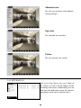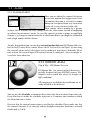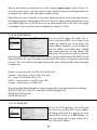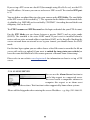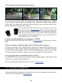
1
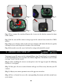
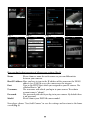
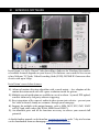
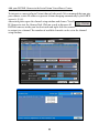
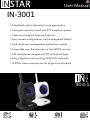
User Manual
IN-3001
/ Scheduled motion detection via image analysis
/ Automatic alarm by email and FTP snapshot upload
/ Video recording via Internet Explorer
/ Easy camera configuration via the integrated WebUI
/ Multi-level user management and access control
/ Accessible over the internet via free DDNS service
/ Full smartphone integration (iOS & Android App)
/ Easy integration into existing WiFi/LAN networks
/ MJPEG video compression for plugin-free playback
3001
Chromium
Firefox
Internet Explorer
Safari
INSTAR
INSTAR VGA IP Camera – Quick Installation
IN-3001
The following topics will be shortly explained in this Quick Installation Guide:
1.
2.
3.
4.
5.
SAFETY WARNINGS...............................................................................3
PRODUCT FEATURES.............................................................................4
INSTALLATION..........................................................................................5
START UP...................................................................................................8
THE WEB USER INTERFACE................................................................11
5.1
SOFTWARE..............................................................................................12
5.1.1
LANGUAGE...................................................................................................12
5.1.2
BACKUP..........................................................................................................12
5.1.3
UPGRADE......................................................................................................12
5.1.4
RESET..............................................................................................................12
5.1.5
REBOOT.........................................................................................................12
5.2
NETWORK...............................................................................................13
5.2.1
IP CONFIGURATION.................................................................................13
5.2.2
WIFI................................................................................................................13
5.2.3
DDNS..............................................................................................................14
5.2.4
UPnP................................................................................................................15
5.2.5
ADSL...............................................................................................................15
5.3
DISPLAY...................................................................................................15
5.3.1
VIEW ON LOAD..........................................................................................15
5.3.2
MULTI DEVICE (only Internet Explorer).................................................15
5.3.3
SIMPLE VIEW...............................................................................................15
5.4
SYSTEM....................................................................................................16
5.4.1
DEVICE INFO...............................................................................................16
5.4.2
ALIAS..............................................................................................................16
5.4.3
DATE&TIME.................................................................................................16
5.4.4
USER...............................................................................................................17
5.4.5
LOG.................................................................................................................17
5.5
ALARM.....................................................................................................18
5.5.1
ALARM...........................................................................................................18
5.5.2
EMAIL.............................................................................................................19
5.5.3
FTP...................................................................................................................19
5.5.4
SERVER...........................................................................................................20
5.5.5
PATH (only Internet Explorer).....................................................................21
1
5.6
MENU BAR...............................................................................................21
5.6.1
SNAPSHOT....................................................................................................21
5.6.2
RECORD (only Internet Explorer)..............................................................21
5.6.3
AUDIO (only Internet Explorer)..................................................................21
5.6.4
TALK (only Internet Explorer).....................................................................21
5.6.6
HELP................................................................................................................21
5.7
VIDEO MENU BAR..................................................................................22
6.
RESET YOUR CAMERA..........................................................................23
7.
FIRMWARE UPDATE..............................................................................24
8.
LENSE ADJUSTMENT.............................................................................24
9.
ANDROID AND iPHONE APP.............................................................25
10.
WINDOWS SOFTWARE.........................................................................27
11.
VIDEO STREAMING...............................................................................29
12.
TECHNICAL DATA.................................................................................30
13.
WARRANTY & DISPOSAL....................................................................31
14.
FAQ Questions&Answers........................................................................32
15.
AVAILABLE ACCESSORIES..................................................................33
More information (German/English) can be found
on www.instar.de
This Quick-Installation Guide
was made exclusively for INSTAR customers.
Your Manufacturer for Network and
Security Technology
2
1 l SAFETY WARNINGS
Please read the following safety warnings carefully and keep them in a safe place.
»» Make sure the power cord is not near any hot surfaces.
»» Place the Power and Network cable properly so that no one can be hurt.
»» This device shall not be used by people (including children) with limited
physical, sensory and mental capabilities. Only the trained person that knows
how to use the device carefully can use the device.
»» Children should be supervised to make sure they don’t play with the device.
»» If the power cord of this device gets damaged, it can only be replaced by the
manufacturer or the customer service person or a similar qualified person to
avoid any damage to you and the device.
»» Never do any repair by yourself. By opening the device the warranty will automatically expire. If any repair is needed, please contact your INSTAR Service Center.
»» When cleaning, never place the device in water.
»» Make sure you only install the device in a 100V - 240V power socket.
»» This device is for indoor use only.
»» Only use this device to secure your home, office and similar places. If you are planning to install the device in an public area please make sure you have all certificates
to do so.
»» Never install the device near explosive or flammable substances.
»» Don’t use the camera for any other purpose that it isn’t made for.
»» INSTAR does not give any warranty if you use any third party firmware or WebUI.
CE-Conformity
This device suites the basic requirements of the European regulations for electromagnetic
compliance (2004/108/EC) and the low voltage regulations (2006/95/EC ).
3
2 l PRODUCT FEATURES
Hardware
»» High Quality Polycarbonate Camera Housing
»» Integrated Alarm I/O Relay for External Sensors or Signalling Devices
»» Resolution: 640 x 480 (VGA), 320 x 240 (QVGA), 160 x 120 (QQVGA)
»» Interchangeable Lenses with a Wide Range of Focal Lengths
»» Microphone and audio output to external speaker / headphones
Connectivity
»» Supported Network Protocols: TCP/IP, HTTP, ARP, RARP, TCP, ICMP, DHCP, UPnP
»» Integrated 10/100Mbit Network Interface
»» Supports W-LAN (Wi-Fi 802.11b/g), LAN and UPnP
»» Integrated Webserver with Web User Interface (based on HTML5/CSS3 and jQuery)
»» Free DDNS Address for Remote Access included
Software
»» MJPEG Video Compression
»» Snapshot Function and Video Recording (the latter only in Internet Explorer!)
»» Adjustable Framerate (only in Internet Explorer)
»» Motion Detection Alarm Notification by Email (6 Snapshots)
»» FTP Snapshot Upload - Continuous and Alarm Triggered
4
3 l INSTALLATION
1
2
7
3
8
4
9
5
6
10
Abb. 2 Rear view
Abb. 1 Front view
11
Alarm-Out
(potential free)
12
13
14
Abb. 3 Side view
1
Antenna
Alarm-In
2.4 dBi SMA Antenna for Wifi connection
2
Network-LED
Shows network activity (deactivate via web user interface)
3
Infrared-LEDs
8 IR LEDs (night vision/850nm)
4
Lense
Standard-Lense (focal length: 6mm)
5
Microphone
Audio-Transmission (Internet Explorer or ASF Stream)
6
Photodiode
Twilight-Switch for IR LEDs
7
Fixing Screw
Screw of the camera stand
Allows you to set your camera to different positions manually
8
Adjustment Screw
9
Network Connector RJ45 connector for provided LAN cable
10
I/O connectors
For external motion detector and alarm indicator
(potential-free alarm output: max. 60VDC/125VAC and 1A)
11
Reset button
Reset to factory settings
12
Audio Output
Headphone connector
13
Power connector
5V/2A DC voltage / plug: 1.35mm inside, 3.5mm outside
14
Camera Stand
Ball joint Connector
5
Connect the camera to your Network
Please take out the package content from the box: the camera, a CAT5e LAN cable, camera stand and the software CD.
Bedienungsanleitung
IN-3001
/ Zeitgesteuerte Bewegungserkennung per Bildvergleich
/ Alarmierung per Email und Schnappschuss Upload per FTP
/ Aufzeichnung des Videos über den Internet Explorer
/ Setzen aller Kameraparameter direkt über die Weboberfläche
/ Mehrstufige Benutzerverwaltung und Zugriffskontrolle
/ Zugriff auf die Kamera aus dem Internet (DDNS)
/ Einbindung der Kamera in Ihr Smartphone (iPhone & Android)
/ Einfache Integration in Ihr bestehendes WLAN/LAN Netzwerk
/ MJPEG Videokomprimierung für Plugin-freie Video-Wiedergabe
3001
Android
iPhone
LINUX
Mac OS
Windows
Please be aware that the camera has to be installed via LAN cable first before it can be used
in your wireless.
router for the initial installation.
Plug the ethernet cabel to the RJ45 LAN port
on the camera case (see #9, page 5) and use it
to connect the camera to a free LAN port of
your LAN router. For a direct connection to
your Windows PC or Mac please refer to our
FAQ section on www.faq.instar.de. We recommend to connect the camera to your network
Connect the power adapter to the camera cable (see #13, page
5) and plug it into a suitable power outlet. Both network indicator LEDs on the network port will light up showing that the
camera is connected to your network.
The green LED signals a hardware link to your router and
therefore should be on continuously. The orange LED
should be flashing irregularly indicating network traffic.
The green status LED on the powersupply has to be on continuously indicating a steady power supply. Please plug the
powersupply directly into a wall socket. Using it on a multi
power strip or an extension cord is not recommended.
6
Troubleshooting
The green LED isn’t on
Your camera doesn’t have a connection to your router, because the LAN cable is damaged, the connector is loose or your camera is connected to a wrong port on your router
or switch.
The green LED goes on and off every x seconds
Your camera is continously restarting - probably because of a loose contact. Please check
the power connector on the camera side. Turn the plug by 180 degrees in both direction
and check if the problem persists. Make sure the green status LED on the power supply
is on continuously.
For a direct cable connection between camera and computer, please note:
The network cable provided with the camera is not a crossover cable. It is just a normal patch cable. Most modern computers network interfaces support the automatic
switching between crossover and normal patch cable - you can use the cable that came
with the camera to connect it directly. If you are using an older system to connect your
camera directly you might need a crossover network cable.
To set up the camera for the first installation we recommend to connect the camera
directly to your router. This router on the other side has to be connected with your computer. Other ways of connections are only recommended to experienced users. Please
refer to our online documentation on www.faq.instar.de.
Connect the camera using an IN-LAN® Adapter (optional)
Simply plug one IN-LAN adapter into a power socket next to your broadband router
and connect the adapter to your router via an Ethernet cable. Plug the second IN-LAN
unit into an outlet close to your INSTAR camera and connect the camera to the IN-LAN
adapter using the camera’s Ethernet cable.
IN-LAN 500/p
Powerline Adapter
IN-LAN uses the household power grid to transfer data between
computers equipped with suitable
adapters and other network components. As a result, any power outlet can be used as a
network access point. IN-LAN is an intelligent and secure technology that lets you set
up a home network easily via your household power grid - without the need of complex
and expensive dedicated cabling.
Additional accessories, like the IN-LAN Adapter, can be found in the accessories of your camera model on www.instar.de and are sold separately.
7
4 l START UP
You can start the online setup wizard manually from the included Installation.htm file on the CD or download the tool directly
from www.download.instar.de. Alternatively simply check your
router log file for a new DHCP address to avoid installing additional software. Your camera will send a
request for an IP address once connected to the router via LAN cable and your router will list the camera
as a new device.
4.1 l NETWORK INSTALLATION
Please start the setup wizard from the CD and install the INSTAR Camera Tool
linked on the CD for Windows, LINUX or MacOS. (You can find documentations
for the use of other IP scanners on www.faq.instar.de) Please start the INSTAR Camera Tool.
The camera tool will automatically find all INSTAR IP cameras in your network
and will show their IP address.
In case your camera isn’t found right away please wait 10 to 15 seconds for your
routers DHCP service to assign an IP address to your camera.
Doubleclick the camera’s IP address inside the camera tool to open the web user
interface (webUI) with your default browser and you will be greeted by the camera’s login window. If so, please skip the following paragraph and go straight to 4.2
THE LOGIN (see page 10).
8
Troubleshooting:
In case the INSTAR Camera Tool doesn’t find your INSTAR IP camera please make
sure that both status LEDs on the LAN connector are active - the green LED should be
continuously on indicating a hardware link and the orange LED should flash irregularly
showing network communication.(see page 7).
In case your camera isn’t automatically assigned an IP address, the camera will be
shown inside a wrong IP address space. A double click on the camera’s IP will then
open the IP / Network configuration window (see below) allowing to manually assign
an address.
Please set the following information according to your network:
- IP Address (for example 192.168.x.x)
- Subnet Mask (for example 255.255.255.0)
- Gateway (IP Address of your router; for example 192.168.x.1)
- DNS Server (IP Address of your router; for example 192.168.x.1)
- Http Port (TCP Port; for example 80)
To check the IP address of your Windows computer and your network parameters
please do the following:
1.
Click on [START] -> and type in „cmd” into the search field.
2.
In the window that pops up please type „ipconfig”.
3.
Now the IP address and the subnet mask will be shown.
9
EXAMPLE:
If your computer’s IP address is “192.168.178.10” then please give your camera an
IP like this “192.168.178.110”. For Subnet mask, Gateway and DNS Server please
use the same settings as for your computer (s. above). If your computer has the IP
“192.168.178.10” then the Gateway and DNS should be “192.168.178.1” and the sub
netmask is “255.255.255.0”.
How to setup your Camera without a router:
If you want to connect your camera directly to your computer, please set a fixed IP
address for the network interface in your computer, as well as for the IP camera. You
can set the camera IP by using the INSTAR Camera Tool. As for Gateway and DNS
server please fill in the computer IP. After submitting the settings to the camera please
wait a moment until the camera has restarted. For a detailed instruction please refer to
our FAQ section on www.faq.instar.de.
4.2 l THE LOGIN
For the first installation of the camera please log in
with the following username and password:
user:
password : admin
<empty>
4.3 l PLUGIN INSTALLATION (only Internet Explorer)
After the login (Internet Explorer) you will be asked to install the ActiveX control
element. Please run it and confirm when your Internet Explorer is asking you to install
the control element:
10
When accessing the webUI for the first time after installation, please allow the installation of the ActiveX control element (only Internet Explorer):
For alternative browsers (Firefox, Chrome, Safari, etc...) no additional Plugins are
needed. You can quickly access your camera’s video stream and adjust its settings. Use
alternative browser on computers where you lack the administration rights to install the
ActiveX plugin (for example in the office).
5 l THE WEB USER INTERFACE
11
5.1 l SOFTWARE
5.1.1 SOFTWARE/LANGUAGE
Here you can choose the language of the
web user interface. The web user interface
will reload after you click submit.
5.1.2 SOFTWARE/BACKUP
To save your camera settings please click
the upper Submit button. The default file
name for the backup is params.bin and
the file path is the download folder of your
browser. To restore the settings, e.g. after a
factory reset, please click Browse to search for the backup file and click Submit to restore
the settings.
5.1.3 SOFTWARE/UPGRADE
You can download firmware and WebUI
updates from our homepage www.download.instar.de and install them using the
Upgrade mask.
5.1.4 SOFTWARE/RESET
Click on Reset to reset your camera’s software to the factory defaults. In case you
misplaced the camera’s password please use
the optional Reset Button (s. S.5 #11) to go
back to the standard login.
5.1.5 SOFTWARE/REBOOT
Click on Reboot to reboot your camera’s
operating system.
12
5.2 l NETWORK
5.2.1 NETWORK/IP CONFIGURATION
You can set whether the camera will be assigned an IP address by your router (DHCP)
or if you want to set a fixed address manually. Please check page 9 on how to set a fixed
IP address. In general, we recommend that
you deactivate the automatic service and set a manual IP to avoid further trouble with
the remote access to your camera.
5.2.2 NETWORK/WiFi
To integrate the camera into you local WiFi
network, please click the Search button
2 times to start the WiFi scanner. Choose
your own network and click on its name.
Now you simply have to add the WiFi password (Share Key) and click submit to save the settings. Please wait for the camera to
reboot - then disconnect the LAN cable. The camera will automatically - within max.
5 minutes - connect to your WiFi network. The camera’s WiFi module might receive a
new address from your router - if you didn’t assign a static IP address to your camera
yet (s. 5.2.1). You might have to use the INSTAR Camera Tool again to rediscover your
camera (s. 4). Your camera is now connected via WiFi!
Attention:
Your WiFi modules MAC address is not identical with the LAN MAC address of your
camera! In case you are using a MAC filtering rule for your WiFi network please deactivate the filter and add your camera to the list of trusted devices before reactivating it.
Please refer to your routers manual for further instructions.
Additional Remark:
Your camera supports a range of encryption standards - we recommend for your safety
and reliability of your connection, that you set your WiFi network to WPA2 (PSK) with
AES (or CCMP). With older routers choose WPA (PSK) / AES. Avoid using a mixed
mode like WPA&WPA2 - TKIP! If your WiFi stays unstable please choose a fixed WiFi
channel for your router - we recommend the channels 1 - 6.
13
5.2.3 NETWORK/DDNS
Your camera comes with a personal DDNS
address - e.g. http://xxxx77.ddns-instar.de.
Everything you need for a remote access to
your camera is a port forwarding rule (s.
next page) in your router. You can access
your camera afterwards through the internet using this http address.
Please visit our online FAQ section on www.faq.instar.de for detailed information on the
port forwarding setup as well as video instruction for many common routers. Or refer to
your router’s user manual for further guidelines on how to set up a port forwarding rule.
EXAMPLE Portforwarding - Netgear:
Please refer to our online help www.faq.instar.de for detailed instructions for all commen routers.
In case you want to use an account from DynDNS.org or NoIP simply choose the third
party service and type in your personal login credentials. By doing so you will temporarily deactivate your INSTAR DDNS address.
In case you are using several cameras behind a single internet access point, please set up
the third party address in only one of the cameras. Or if possible directly inside your
router! All your cameras will be accessible through this address - just assign a unique
HTTP port to every camera (s. 5.2.1). For example if camera 1 is assigned the HTTP
port 85 and camera 2 the HTTP port 86, use myaddress.dyndns.org:85 to reach camera 1
and myaddresse.dyndns.org:86 to be forwarded to camera 2.
14
5.2.4 NETWORK/UPnP
If you are using Universal Plug and Play for
your network devices. Please activate the
UPnP service in your camera. In case you
are using a manual port forwarding rule in
your router to access your camera from the internet, make sure the camera’s UPnP service is deactivated! We recommend setting up a manual port forwarding.
5.2.5 NETWORK/ADSL
You can use the ADSL function to use the
camera directly plugged into a ADSL modem instead of a network router. Simply use
the login from your internet service provider.
5.3 l DISPLAY
5.3.1 DISPLAY/VIEW ONLOAD
Use the View OnLoad function to set the
default view - you can choose between the
Setup View and a Simple View.
5.3.2 DISPLAY/MULTI DEVICE (only Internet Explorer!)
Use the Multi Device mask to add cameras
to your live view. Just add the camera’s IP
or DDNS address and user login and click
Add. Repeat the step for additional cameras and click Submit. Then choose a corresponding grid type in your Live-View Tab:
5.3.3 DISPLAY/SIMPLE VIEW
The Simple View is designed for your daily use
after you finished the initial setup of your camera.
You can click on Setup View to return to the extended menu.
15
5.4 l SYSTEM
5.4.1 SYSTEM/DEVICE INFO
The Device Info menu gives you an overview
of several important camera parameters like your software version and connection
status.
5.4.2 SYSTEM/ALIAS
Set an Alias for your camera to identify the
camera in your network.
5.4.3 SYSTEM/DATE&TIME
You can set up the internal clock of the
camera to be either synchronised with your
PC clock or with one of several NTP servers. As long as your camera has access to the
internet it is recommended to use an NTP
server synchronisation to achieve a higher accuracy for alarm trigger events. Please activate “Consider Daylight Saving Time” when in effect.
5.4.4 SYSTEM/USERS
The web user interface offers a 3-level user
management with different access rights for
administrators, operators and visitors. You
can set user names and passwords for all
three user levels in the Users mask. Visitors
will only have access to the videostream of
the camera, Operators in addition are able to adjust the video settings and only the Administrator will have access to all the camera’s configuration menus.
16
Administrator
The web user interface with administrator privileges.
Operator
The standard user interface.
Visitor
The user interface for visitors.
5.4.5 SYSTEM/LOG
The Access Log shows you every login to
the camera as well as the IP address of the
incoming connection. Additionally you can
find general notifications from the camera’s
operating system such as motion alerts.
17
5.5 l ALARM
5.5.1 ALARM/ALARM
Here you can adjust the camera’s behaviour
in case of a motion alert trigger event. Once
the motion detection is activated, its sensitivity can be adjusted from very insensitive
(value=0) to very sensitive (value=10).
Your camera detects motion by a picture
analysis that is sensitive to every change inside the video frame instead of employing
an infrared or microwave sensor. In case the camera’s position is prone to rapid light
changes, e.g. changes in sun intensity due to cloud movements, you might be confronted
with a high number of false alarms.
300
To solve this problem you can attach an external motion detector (IN-Motion 300; s.below) to the I/O relay of the camera. Please check “Activate External Input” to start using
the external sensor and set the trigger level according to your devices demands. Please
only activate the external input if an external sensor is connected - since you might receive false alerts otherwise.
Motion
IN-Motion 300
Plug & Play - PIR Motion Detector
IN-Motion 300 - the passive infrared detector especially designed for your INSTAR camera. The
simplest way to avoid false alerts by changes in
light conditions.
All components needed for the installation are already included in the delivery !
Additional accessories, like the IN-Motion 300, can be found in the accessories of your camera on www.instar.de and are not part of the scope of
the delievery.
You can use the Scheduler to automatically activate the alarm in desired time intervals.
Every blue box set inside the scheduler represents a 15 minutes time window in which
the alarm function is active.
Be aware that the internal camera time is used for the scheduler. Please make sure that
the camera’s timezone is set correctly and the daylight saving time function is activated
if indicated (s. 5.4.3).
18
You can also attach an external device to the camera’s signal output - please check “Activate External Output” to let the camera send a signal to your external signal device or
to integrate the camera into your home burglar system.
Below that you can set whether in case of an alarm you want to receive an email or have
the alarm snapshots send to your FTP server. Please be advised that you will have to set
your SMTP login first (s. 5.5.2) to receive an alarm email and set the FTP server login
accordingly if you want the camera to upload the images (s. 5.5.3).
5.5.2 ALARM/EMAIL
Here you need to input the sender, the receivers and your SMTP server login to be
notified by email in case of an alarm. The
sender address should be set in accordance
with the SMTP server login data, though
some email providers let you choose this
field freely. If you want to send the email to
more than one address, simply add more addresses in the fields below. The SMTP Server
login should be the same username and password that you use to login to your email
account. The server address and port depends on your email provider. Some common
examples are:
Gmail - smtp.googlemail.com (SSL; Port 465 or 587)
Verizon - outgoing.verizon.net (SSL; Port 465)
O2 - smtp.o2.co.uk (Port 587 or 25)
AT&T - smtp.att.yahoo.com (SSL; Port 465)
Orange - smtp.orange.co.uk (Port 25)
The chosen Port often depends on the encryption that your email provider is offering:
SMTP AUTH: Port 25 or 587 (some ISPs are blocking port 25)
SMTP StartTLS Port 587
SMTP SSL Port 465
5.5.3 ALARM/FTP
To use the FTP upload (s. also 5.5.1) you
first have to set your FTP server address
and login credentials. E.g. you can use your
routers FTP service as a FTP Server - in
this case simply put in your routers IP as
the FTP Server address.
19
If you set up a FTP server on a local PC (for example using Filezilla Server), use the PC’s
local IP address. Of course you can use webservers URL’s as well. The standard FTP port
is 21.
You can define an upload directory for your camera under FTP Folder. The root folder
of the FTP server can be reached by “/”. The separator for the folders is the forward slash.
A subfolder (e.g. INSTAR) can be reached by “/INSTAR”. An ending forward slash is not
obligatory, but can be used.
The FTP Username and FTP Password are the login credentials for your FTP Account.
For the FTP Mode you can choose between a passive (PASV) and an active mode
(PORT). The standard is the active PORT mode. If your server is installed behind a
router with an active network address translation (NAT), or if a firewall is blocking the
servers network from an external access by your camera, you should choose the PASV
mode.
For the time lapse option you can either choose a fixed file name to override the file on
server with each new upload (if you want to embed the image into your website) or
leave the name field blank to let the camera generate a filename from a timestamp.
Please refer to our website www.faq.instar.de for information on how to set up a FTP
server.
5.5.4 ALARM/SERVER
You can use the Alarm Server function to
send a http request to a connected server.
The server needs a compatible software to
recognize this request as an alarm event
and trigger further actions. This function is often supported by home alarm systems.
Please add the http prefix when entering the servers IP address - e.g. http://192.168.0.22.
20
5.5.5 ALARM/PATH (only Internet Explorer!)
Here you can set the record path for the video recording function under Internet Explorer. The record paths are both set globally by the ActiveX Control - you therefore
only need to set it in one camera in case you
are managing more than one in the ActiveX
Multiview.
5.6 l MENU BAR
5.6.1 MENU BAR/SNAPSHOT
Click on Snapshot to save a single JPG snapshot of the
current video frame. For Internet Explorer the snapshot will be saved locally in the
download directory. Otherwise the snapshot will be opened in a new browser window
or tab and can be downloaded from there.
5.6.2 MENU BAR/RECORD (only Internet Explorer)
Click on Record to manually start a video recording. The
Video will be saved in the record directory set in 5.4.4. In case you use more than one
camera this directory will be used globally.
5.6.3 MENU BAR/AUDIO (only Internet Explorer)
Click here to activate the camera’s audiostream. To access
the camera’s audio with other clients (e.g. VLC Player) please use the direct path <IP
address of your Camera>/videostream.asf.
5.6.4 MENU BAR/TALK (only Internet Explorer / only via external speaker)
Use the Talk function to send an audio signal from your
PC’s microphone to the camera’s audio-out.
5.6.5 MENU BAR/HELP
Clicking on Help will bring you to our constantly expanding online FAQ section on www.faq.instar.de.
21
5.7 l VIDEO MENU BAR
The Video Menu Bar allows you a quick access to the
most important video parameter. Please be aware that the
timestamp and frame rate function are only available in
the ActiveX mode (Internet Explorer).
If you notice that the automatic brightness control doesn’t
seem to work (e.g. you get a white screen after sunrise),
please set the default values (brightness: 6 and contrast:
4) and switch the mode from “outdoor“ to “50Hz” or
“60Hz” and then back to “outdoor”. The automatic brightness control is active again until you change either the
brightness or contrast and switch the camera back to the
manual mode.
If you find the checkboxes “Flip” and “Mirror” not functioning, please delete your
browsing history.
Please be aware that the InstarVision Windows Software can override the “Flip” and
“Mirror” settings from your camera’s WebUI. Please set those functions inside both
software accordingly.
Check the Alarm box to activate or deactivate your camera’s alarm settings. Use the
Relay function to switch the camera’s alarm I/O- for example to activate or deactivate a
device connected to the alarm output (see page 5 #7).
22
Menu Bar
Video
Menu Bar
6 l RESET YOUR CAMERA
In order to reset your camera (if you have lost your password), please hold the small
reset button (see 5 #11) for min. 15 seconds. Please make sure the camera is connected
to the power supply and disconnected from the LAN cable. In case that the reset was
incomplete the camera might become inresponsive. Please repeat the reset for min. 15 s
and unplug it over night from the power supply before trying to restart it again.
23
7 l FIRMWARE UPDATE
INSTAR regulary offers updates for your camera’s firmware and for the integrated user
interface. There are currently two ways to update to newer versions of your devices firmware and WebUI. You can choose to do the update process either through the Camera
Tool or directly within the WebUI itself.
Step 1: Visit our website and download the most recent update files for your camera.
Step 2: Run the INSTAR Camera Tool. Then choose “Update” and select the camera you
want to update. A login prompt will pop up and ask for your user data. Make sure to
login with an admin account.
Step 3: Please choose either Firmware or WebUI, depending on what you want to update. Then click on “Browse” to select the corresponding update file on your hard drive.
Step 4: Make sure you have selected the right file before clicking the “Submit” button.
This will upload the update file into your device and reboot the camera.
Updates via WebUI follow a similar process. It doesn’t matter which method you choose.
WARNING: During the update process, please make sure NOT to cut the power supply.
This may cause irreversible damage to your device.
8 l LENSE ADJUSTMENT
The IN-3001’s lense offers a limited field depth that was adjusted to a field between 1m to
10m. In case the object you want to observe lies outside of this area, you will have to adjust the lense accordingly. Simply open the camera from the front and turn the lense until you can see the plane of your surveillance coming into focus in the web user interface.
24
Fig. 1
Fig. 2
Fig. 3
Fig. 4
Fig. 1 Please remove the stand and loosen the 4 screws in the back to remove the front
of the camera.
Fig. 2 Lift the cover off the camera casing to get to the camera’s lense inside the CMOS
mount.
Fig. 3 Now access the live video via the web user interface and adjust the focus by gently
turning the lense until the picture becomes clear and sharp.
Fig. 4 Afterwards screw the cover back to the casing and reattach the stand.
9 l ANDROID AND iPHONE APP
To integrate your IP camera in the Android/iPhone App “InstarVision” we recommend
to first download the newest version in the Market/App Store. To find the newest version
just type “instar” for the search.
(Fig. 1) After installing the newest version please start the App to open the following
interface (s. next page).
(Fig. 2) Now press the new camera button and type in all necessary data for your IP
camera.
(Fig. 3) Adjust your camera parameter over the apps user interface.
(Fig. 4) Press a channel to access the corresponding livestream and take control over
your camera.
25
Fig. 1
Fig. 2
Fig. 3
Fig. 4
Here you find a short overview of all necessary settings (Fig.2):
Name: Please choose a name for each camera so you can differentiate between your cameras.
Host/IP Address:Here you have to type in the IP address of the camera or the DDNS
address (see 5.2.3) to access the camera over the internet.
Port:
Type in the HTTP Port which you assigned to your IP camera. The standard Port is “80”.
Username:
The username with which you log in to your camera. The admin
account name is “admin”.
Password:
The password with which you log in to your camera. By default there is no password.
Model:
Please choose your INSTAR camera model.
Now please choose “Save/Add Camera” to save the settings and to return to the home
screen (Fig.1).
26
10 l WINDOWS SOFTWARE
sold separately
InstarVision® is a 16/32 Channel Video Surveillance Software for Windows (the number
of available channels depends on your license!) The Software can record the live stream
of any Webcam, TV Cards, Video-Recording Cards (DVR), INSTAR IP Camera or other
devices with up to 30 fps.
InstarVision® covers below features:
1). Advanced motion detection algorithm with a mask matrix – free adaption of the
motion detection mask with a 64 square resolution inside the picture.
2). Multiple ways of notification are available in case of an alarm - by email, FTP upload,
acoustic alarm or by 3rd party software triggering.
3). Easy integration of the camera’s audio & video stream into websites - present your
live video to friends, family or customers through your homepage.
4). Support for multiple video output formats: such as MP4, MOV, FLV, SWF, WMV
and AVI and video codecs like H.264, MPEG4 and WMV3.
5). An affordable price and all the functions necessary to achieve your camera’s full
potential.
A detailed online manual can be found on www.instarvision.de and a 7-day trial version
can be downloaded from our homepage www.download.instar.de.
27
Add your INSTAR Camera to the InstarVision® Surveillance Center:
To integrate a camera in InstarVision it doesn’t take much. We recommend that you give
your camera a static IP address to prevent it from changing automatically by the DHCP
server. (s. 5.2.1).
Afterwards please open the channel setup window and choose “Search”
IP Camera to start the Camera Tool. Click on search to discover all
INSTAR cameras inside your local network and right-click the cameras
to assign it to a channel. The number of available channels can be set in the channel
setup window.
28
11 l VIDEO STREAMING
(e.g. VLC Player, iSpy, VitaminD, EvoCam, go1984...
To use third party software you sometimes need the direct path for the live video in order to grap the video from your camera. Then the program is able to get the videostream
from your camera to work with it. You can find a selection of compatible software and
detailed step-by-step instructions on how to integrate your camera in our FAQ section
on www.faq.instar.de.
Access over the local network:
Please use the following path to use your camera with third party software.
MJPEG:
ASF Stream: Snapshot: http://192.168.x.x:80/videostream.cgi?user=admin&pwd=
http://192.168.x.x:80/videostream.asf?user=admin&pwd=
http://192.168.x.x:80/snapshot.cgi?user=admin&pwd=
x = local IP address of your camera (for example 192.168.0.21)
The “80” after your camera’s IP is the web/http port. If the web port has been changed in
the camera menu (network/network) please adjust it here as well.
Access over the Internet:
To access your camera via the internet you first have to set a port forwarding rule
inside your router on the camera’s IP address!
Please refer to the DDNS Service section above (5.2.3) or visit our websites FAQ’s on
www.faq.instar.de to find detailed step-by-step instruction for all common routers.
http://xxx.ddns-instar.de:yy/videostream.cgi?user=admin&pwd =
xxx = from your personal DDNS address (see 5.2.3 Network/DDNS Service)
yy = the camera’s HTTP Port (Standard: 80)
user = please change the “admin” if you already set a different user name for your
camera login!
pwd = add your password after the “=” sign in case you set a personal password for
your camera login. The password is left blank by default.
29
12 l TECHNICAL DATA
Image Sensor
Sensor
1/5 ” CMOS colour sensor
Resolution
max. 640x480 Pixel
Lense
f = 6mm; F 2.0 (IR Lense)
Viewing Angle
37°
Min. Illumination
0.5 Lux @ F 2.0
Video Properties
Video Compression
MJPEG Compression
Video Framerate
30fps (QVGA), 15fps (VGA)
Supported Resolutions
640x480 (VGA), 320x240 (QVGA)
Flip/Mirror Image
Horizontal / Vertical
Frequency Adjustment
50 Hz, 60 Hz or “Outdoor”
Motion Detection
Supported
Snapshot
Supported
Video Settings
Brightness / Contrast
Communication
Network Interface
10Base-T/100Base-TX Ethernet Port
Supported Protocols
TCP/IP, HTTP, ARP, RARP, TCP,
ICMP, DHCP
WLAN
Wifi 802.11b/g
WEP Encryption
64 bit / 128 bit
WPA/2 Encryption
TKIP / AES
Hardware
Infrared LED’s
10 LED’s / Effective Range 8m
Audio
2-Way Audio (loudspeaker needed)
Power Supply
DC 5V /2A (50-60Hz/110-220V)
Power Consumption
max. 5 W
Operating Temperature
- 5°C to 55°C
PC System Requirements
CPU
2GHz or better
System Memory
256 MB or better
Graphic Card Memory
64 MB or better
Supported Operating Systems
Windows XP / Vista / 7 / 8, Mac OS,
Linux, iOS, Android
30
13 l WARRANTY & DISPOSAL
Warranty
INSTAR offers a 2-year warranty on its products. During this period you can send in
your camera for a free repair. This excludes cameras installed with custom-made or 3rd
party Firmware and WebUIs which have not been approved by INSTAR. The warranty
is only for hardware parts of the camera.
If you are contacting our Service Team please keep your model and serial number
ready. If you want to send your camera for repair, please use the RMA form that came
with your camera. You can also download it from our website www.instar.de or contact
the INSTAR Service Team.
You can find your INSTAR SERVICE CENTER at the following destination:
Company:
INSTAR Deutschland GmbH
Auf der Hostert 17
65510 Hünstetten Bechtheim
Germany
Hotline: +49 6438 9198992
(Mo - Fr, 12 – 18 o’clock GMT+1)
Website: www.instar.de
Email: [email protected]
WE WILL HELP YOU ANY TIME AFTER YOUR PURCHASE!
Disposal of old electrical appliances
The European Directive 2002/96/EC on Waste Electrical and Electronic Equipment
(WEEE), requires that old household electrical appliances must not be disposed of in
the normal unsorted municipal waste stream. Old appliances must be collected separately in order to optimize the recovery and recycling of the materials they contain and
reduce the impact on human health and the environment. The crossed out “wheeled
bin” symbols on the product reminds you of your obligation, that when you dispose
of the appliance it must be separately collected. Consumers should contact their local
authority or retailer for information concerning the correct disposal of their old appliance.
31
14 l FAQ
1) Where can I set the language of the camera’s web interface?
The camera automatically detects the language setting of your operating system and adjusts the user interface accordingly. In case you need to override the camera setting,
please go to Software/Language to choose a custom setting:
2) Why are some objects shown grayish/ pinkish instead of green?
The lense in the camera does not use an Infrared filter. This is why your camera can see
at night but shows false colours during sunlight. You can install an IR Filter lense from
our accessories to get around this problem - but you will loose the night vision. The alternative is an automatic IRcut filter that is only deployed during the day - still allowing
you to use the nightvision functionality.
Only cameras without a pre-installed auto IRcut filter will be affected!
f2.2mm without IR Filter
f2.2mm with IR Filter
Please feel free to browse our wide variety of lenses with focal lengths from the wideangle range to the telefocus end of the scale. Please behold that by installing a lense with
an IR Filter you will lose the nightvision capabilities of your camera! In case you
need both - natural colours during the day and the camera’s nightvision - please refer
to the automatic IRcut Filter from your camera’s accessories page on www.instar.de
(not compatible with all camera models).
32
3) Can I change the angle of view of my camera?
In case you are unsatisfied with the standard lense (6mm focal length, above, middle)
you can upgrade your camera to a wideangle lense (2.2mm focal length, above, left) or
go the other way and install a telefocus lense to keep an eye on the finer details in the
picture (16mm focal length, above, right).
You can find a suitable lense for every surveillance task in our
accessory section on www.instar.de. Please be aware that you will
gain more and more level of detail in your image the smaller the
angle of view of your camera. Lense charts with all the information needed are available on our website - so you can pick the best
focal length for your surveillance.
4) Where can I download the newest Firmware / WebUI?
You can find the latest Firmware and WebUI on www.instar.de in the category “Downloads”.
5) How can I find out the MAC Address of the Wi-Fi Network Interface?
Deactivate the Routers MAC Address Filter. Connect the camera with Wi-Fi and access
the web interface of the camera shortly. Now please go on “Start” in Windows and then
on “Run”. Type “cmd” and press “Enter”. In the Dos-Window please type in “arp –a”. You
will now get the IP and MAC Addresses listed which your PC is connected with.
6) Are the other cameras compatible with this camera?
Yes, all INSTAR VGA cameras are using the same or similar chipsets which allows each
camera to be combined with another one.
For more Information and FAQs please visit us on www.instar.de .
15 l AVAILABLE ACCESSORIES
We are continously expanding our range of accessories. For a complete overview please
refer to our accessory page on www.instar.de .
33
PERSONAL NOTES
34