1
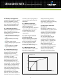
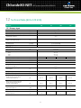
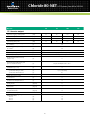
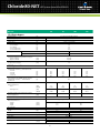
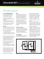
AC Power for
Business-Critical Continuity™
Chloride 80-NET from 60 to 500 kVA
UPS Catalogue
Chloride80-NET UPS Systems from 60 to 500 kVA
Chloride 80-NET
UPS Systems from 60 to 500 kVA
Scope 4
System Description
4
Device Description 5
General Requirements
8
AC/DC IGBT Converter (Rectifier) 9
DC/DC IGBT Converter (Booster/Battery Charger)
10
DC/AC IGBT Converter (Inverter) 12
Electronic Static Switch (Bypass)
14
Monitoring and Control, Interfaces
15
Mechanical Data 18
Environmental Conditions 18
Technical Data (60 to 120 kVA)
19
Technical Data (160 to 500 kVA)
23
Options 27
Parallel Configuration
29
3
Chloride80-NET UPS Systems from 60 to 500 kVA
1 Scope
2 System Description
This specification describes a
The single-line diagram of the UPS is shown in Figure 1. The system features
double DSP and a micro-controller that provides the most powerful control in
the UPS industry. The Vector Control technology will enhance the performance
of these converters.
In order to increase system redundancy, an independent electronic static
bypass will be integrated into the UPS. By adding system components,
CROSS switches, safety and disconnecting devices, system bypass switches, in
addition to software and communications solutions, it will be possible to set up
elaborate systems to ensure the complete protection of the loads.
continuous duty three-phase,
solid state, full IGBT
(Insulated Gate Bipolar Transistor),
double conversion uninterruptible
power supply (UPS) system. The UPS
will automatically provide continuity
of electrical power, within defined
limits and without interruption,
2.1 The system
upon failure or degradation of the
The UPS will provide high quality AC power for electronic equipment loads and
will offer the following features:
• Increased power quality
• Full input Power Factor Correction (PFC) and very low THDi
• Full compatibility with any TN and IT installation
• Full compatibility with any standby power generator
• Full compatibility with all types of loads with PF up to 1 without derating
• Power blackout protection
• Advanced battery care
• Energy saving features
• Transformer-free design (galvanic isolation transformer is available as
integrated standard option)
The UPS will automatically provide continuity of electrical power, within
defined limits and without interruption, upon failure or degradation of the
commercial AC source. The duration of autonomy (i.e. back up power time)
in the event of network failure will be determined by the battery capacity.
commercial AC source.
The continuity of conditioned
electric power will be delivered
for the time period defined by the
battery system.
The rectifier, the inverter, and other
mission critical converters within the
UPS, are driven by patented Vector
Control running on dedicated digital
signal processor (DSP) systems.
2.2 Models available
The Chloride 80-NET range will include the following three-phase input/
output models:
MODEL
Maintenance Bypass
Bypass static
switch
Bypass Input
IGBT
Rectifier
IGBT
Inverter
Primary Input
Output Load
Fuse
Fuse
Booster/Battery
charger
Battery Fuse
Chloride LIFE®.net
Basic signalling
Battery Fuse
Optional remote
Connectivity
(IP; SNMP; J-BUS;Etc.)
Battery System
Figure 1. Chloride 80-NET single-line diagram.
4
Rating (kVA)
Chloride 80-NET/60
60
Chloride 80-NET/80
80
Chloride 80-NET/100
100
Chloride 80-NET/120
120
Chloride 80-NET/160
160
Chloride 80-NET/200
200
Chloride 80-NET/300
300
Chloride 80-NET/400
400
Chloride 80-NET/500
500
Chloride80-NET UPS Systems from 60 to 500 kVA
3 Device Description
Chloride 80-NET is the result
of an innovative research and
development programme designed
to offer users the most reliable power
supply at a minimum cost and the
highest possible energy conversion
efficiency.
3.1 Components
The UPS will consist of the following
major components:
• IGBT Rectifier
• IGBT Battery Charger / Booster
• IGBT Inverter
• Dedicated digital signal processor
(DSP) for each IGBT AC/DC, DC/AC
converter
• Micro-controller board for internal
and external signal management
• Electronic static switch and bypass
supply
• Manual maintenance bypass
switch
• Matching battery cubicles
3.2 Microprocessor control
and diagnostics
Operation and control of the UPS
will be provided through the use
of microprocessor- controlled
logic. Indications, measurements
and alarms, together with battery
autonomy, will be shown on a
graphic liquid crystal display
(LCD). The procedures for start up,
shutdown and manual transfer of
the load to and from bypass will
be explained in clear step-by-step
sequences on the LCD display.
3.3 Intelligent double conversion operating modes
Chloride 80-NET will adopt intelligent double conversion technology which
allows the UPS to operate in double conversion or digital interactive mode
according to the selected priority. The UPS will operate as follows:
3.3.1 Double Conversion Mode (DCM)
3.3.1.1 Normal (DCM)
The UPS inverter continuously supplies the critical AC load. The rectifier
derives power from the commercial AC source and converts it into DC power
for the inverter and the battery charger. The battery charger keeps the
battery in a fully charged and optimum operational condition. The inverter
converts the DC power into clean and regulated AC power which is supplied
to the critical load (conditioned line). The static switch monitors and ensures
that the inverter tracks the bypass supply frequency. This ensures that any
automatic transfer to the bypass supply (due to an overload etc.) is frequency
synchronized and does not cause interruption to the critical load.
3.3.1.2 Overload (DCM)
In the event of an inverter overload, manual stop or failure, the static
switch will automatically transfer the critical load to the bypass line without
interruption.
3.3.1.3 Emergency (DCM)
Upon failure or reduction of the commercial AC source (see the Technical
Data table for tolerances) the inverter will supply the critical load, drawing
power from the associated battery through the battery Booster.
There will be no interruption to the critical load upon failure, reduction or
restoration of the commercial AC source. While the UPS is powered by
the batteries, indications will be provided of actual autonomy time
remaining as well the duration of the mains failure.
3.3.1.4 Recharge (DCM)
Upon restoration of the commercial AC source, even where batteries are
completely discharged, the rectifier will restart automatically (walk in) and
gradually take over both the inverter and battery charger. This function will
be fully automatic and will cause no interruption to the critical load.
5
Chloride80-NET UPS Systems from 60 to 500 kVA
3.3.2 Digital Interactive Mode (DIM)
If priority has been set to digital
interactive mode, intelligent double
conversion technology will allow
Chloride 80-NET to continuously
monitor the condition of the input
supply, including its failure rate,
to ensure maximum reliability for
critical users. On the basis of the
analysis performed, it will decide
whether to supply the load through
the direct line or the conditioned
line. This operational mode, which
allows significant energy savings
by increasing the overall AC/AC
efficiency of the UPS, up to 98%,
is primarily intended for general
purpose ICT applications. However,
it does not provide the same output
power quality as when the UPS
operates in double conversion
mode. It will therefore be necessary
to verify whether this mode is
appropriate for special applications.
Digital interactive mode is not
available for parallel systems.
3.3.2.1 Normal (DIM)
The operating mode will depend
on the quality of the mains supply
in the short-term past. If the
line quality has remained within
permitted tolerance parameters in
this timeframe, the direct line will
provide continuous supply to the
critical AC load through the bypass
static switch. The IGBT inverter
control will remain in constant
operation and synchronization
with the direct line without driving
the IGBT. This ensures that the
load can be transferred to the
conditioned line without any
break in supply where there is a
deviation from the selected input
power tolerance levels. If the direct
line failure rate has been outside
permitted parameters, Chloride
80-NET will supply the load from
the conditioned line. The battery
charger supplies the energy
necessary for maintaining maximum
charge to the battery.
3.3.2.2 Inverter stop (DIM)
If the inverter is stopped for any
reason there is no transfer to the
conditioned line and the load
continues to be supplied by the
direct line. The mains voltage and
frequency values must be within
the tolerance limits specified.
3.3.2.3 Overload (DIM)
In the event of an overload with a
duration in excess of the maximum
capacity specified for the bypass
static switch, the load is maintained
on the direct line and a warning
message on the LCD display will
appear to warn the user about
the potential risk related to this
condition. This default behavior
can be changed (via a Service
accessible firmware setting) to
force a load transfer to the
conditioned line (similar to that
described below), even if the bypass
source is available. In the event of
an overload in conjunction with an
unsuitable bypass mains supply,
Chloride 80-NET will transfer the
load from the direct line to the
conditioned line (assuming
Chloride 80-NET was operating from
the direct line) and the inverter
will continue to supply the critical
load for a period dependant on the
6
degree of the overload and the UPS
features. Visual and audio alarms
alert the user to the problem.
3.3.2.4 Emergency (due to mains
supply failure or variance beyond
tolerance limits, DIM)
If Chloride 80-NET is supplying
the load via the direct line and the
bypass mains supply varies beyond
tolerance levels (adjustable using
the software), the load will be
transferred from the direct line to the
conditioned line. The load is powered
from the mains via the rectifier and
inverter, (provided the input mains
remains within the tolerances stated
in chapter 12 & 13). Should the input
mains fall below the lower limit,
the batteries will be used to power
the load via the inverter. The user
is alerted to the battery discharge
by visual and audio alarms and the
remaining autonomy is displayed
on the LCD. During this process, it
is possible to extend the remaining
autonomy by switching off nonessential loads.
3.3.2.5 Return to normal
conditions (DIM)
When the mains supply returns to
within tolerance limits,
Chloride 80-NET will continue to
supply the load via the conditioned
line for a period of time dependant
on the direct line failure rate (the
conditioned line draws power from
the mains not the battery).
When the direct line has stabilized,
Chloride 80-NET returns to normal
operation. The battery charger
automatically begins to recharge
the battery so that maximum
autonomy is guaranteed in the
shortest possible time.
Chloride80-NET UPS Systems from 60 to 500 kVA
3.3.3 Maintenance bypass
The UPS will be fitted with an
internal maintenance bypass switch
which enables a load transfer to
bypass supply. As a result, there will
be no interruption to the power of
the critical load when it is necessary
to take the UPS out of service
for maintenance or repair. Bypass
isolation will be complete and all
serviceable components such as
fuses, power modules etc will be
isolated. Transfer/retransfer of the
critical load may be accomplished
by automatic synchronisation of
the UPS to the bypass supply and
by paralleling the inverter with the
bypass source before opening or
closing the bypass switch as
appropriate.
3.3.4 Operation without battery
If the battery is taken out of
service for maintenance, it has to
be disconnected from the UPS by
means of an external switch (e.g.
situated in the battery cabinet).
The UPS will continue to operate
and meet the performance criteria
specified with the exception of the
battery backup time.
3.4 Control and diagnostics
Control of the power electronics modules will be optimized in order to
provide:
• optimum three-phase supply of the load
• controlled battery charging
• minimum phase effects upon the supply network.
Chloride 80-NET’s control platform incorporates double DSP and a microcontroller, allowing it to provide the most powerful control in the UPS
industry. This platform combines the advantages of a double DSP which
executes all the Vector Control algorithms and the Microcontroller which gives
maximum communication flexibility whilst interfacing all internal and external
signals.
3.4.1 Vector control
To ensure the quick and flexible processing of measuring data, special
arithmetic algorithms will be implemented in DSP, rapidly generating
controlled variables as a result. This will thus render possible the real-time
control of the inverter electronics, resulting in obvious advantages in the
performance of the power components. These advantages will be:
• Improvement of short circuit behaviour, as individual phases can be more
quickly controlled
• Synchronism or phase angle precision between UPS output and bypass
supply even in the case of a distorted mains voltage
• High flexibility in parallel operation: parallel blocks may be housed in
separate rooms.
Several algorithms included in the Vector Control firmware are covered by
patents.
3.4.2 Redundancy, preventive monitoring
In order to maximize the reliability of the system, the control unit will monitor
a wide number of operating parameters for the rectifier, inverter and battery.
All vital operating parameters, such as temperatures, frequency and voltage
stability at the system input and output, load parameters and internal system
values will be constantly monitored and controlled for irregularities.
The system will react automatically before a critical situation arises either for
the UPS or the load, in order to ensure the supply of the load even in these
difficult conditions.
3.4.3 Telediagnosis and telemonitoring
In all the above modes of operation, the UPS may be monitored and controlled
from a remote location such as a service center, in order to maintain system
reliability at nominal levels. Even during complete shutdown of the UPS,
information relating to the operating parameters will not be lost thanks to non
volatile FRAM which will store the information for up to 45 years.
7
Chloride80-NET UPS Systems from 60 to 500 kVA
4 General Requirements
3.4.4 Serviceability and
commissioning
The new Chloride 80-NET is
designed for easy installation and
serviceability thanks to the drawerdesign, making it a full modular
service solution and considerably
minimising the time needed for
repairs.
All functional modules can be
removed by extracting the drawers
from the front of machine.
Each UPS will be equipped with
ID card, including all UPS working
parameters. This card, univocally
related to the UPS, reduces the
MDT to zero shortening service and
commissioning operations.
4.1 Applied standards
Emerson Network Power operates Quality Management Systems which
comply with ISO 9001, as well as Environmental Policies and Management
Systems that comply with ISO 14001.
Chloride 80-NET will carry the CE mark in accordance with the Safety European
Directive 2006/95 (superseding the 73/23 and successive amendments)
and European EMC directive 2004/108 (superseding the 89/336, 92/31 and
93/68). Chloride 80-NET is designed and manufactured in accordance with the
following international standards:
• IEC/EN62040-1-1 general and safety requirements
• EN62040-2 EMC requirements
• IEC/EN62040-3 operating requirements.
• Classification according to IEC/EN 62040-3: VFI-SS-111
4.2 Safety
In terms of general and safety requirements, the UPS conforms to standard
IEC/EN 62040-1-1 governing use in unrestricted access locations.
4.3 EMC and surge suppression
Electromagnetic effects will be minimzed in order to ensure that computer
systems and other similar electronic loads will neither be adversely affected
by nor affect the UPS. The UPS will be designed to meet the requirements of
EN 62040-2, class C3. The manufacturer and customer in partnership agree
to ensure the essential EMC protection requirements for the specific resulting
installation.
4.4 Neutral connection
The Chloride 80-NET output neutral will be electrically isolated from the UPS
chassis. The input and output neutral connections are the same, i.e. they are
solidly tied together. Therefore the UPS will not modify the state
of the upstream neutral, in any operating mode, and the neutral state of the
distribution downstream from the UPS is imposed by the mains one.
4.5 Materials
All materials and components including the UPS will be new and of current
manufacture.
8
Chloride80-NET UPS Systems from 60 to 500 kVA
5 AC/DC IGBT Converter (Rectifier)
5.1 Primary input
The three-phase current taken from
the commercial AC source will be
converted to a regulated DC voltage
by the IGBT rectifier. In order to
protect the power components
within the system each phase of the
rectifier input will be individually
fitted with a fast-acting fuse. As
shown in Figure 1, the IGBT rectifier
will provide DC power to the DC/AC
output converter (IGBT inverter)
and to the DC/DC battery converter
(booster / battery charger) when the
latter is working in battery charger
mode.
5.2 Total Input Harmonic
Distortion (THD) and Power
Factor (PF)
The maximum voltage THD (THDV)
permitted on the rectifier input
(either from the utility or generator)
will be 15% (normal operation is
guaranteed up to 8%).
The maximum current THD injected
into the mains (THDI) will be less
than 3% at maximum input power
and input voltage THDV < 1%
(nominal input voltage and current).
The input power factor (PF) will be >
0.99. Under other input conditions
and with other output load fractions
the THDI will be < 5%. This means
that the Chloride 80-NET will be
seen by the primary mains sources
and distribution as a resistive load
(i.e. it will absorb only active power
and the current waveform will be
practically sinusoidal), thus ensuring
total compatibility with any power
source. Chloride 80-NET includes all
the performances offered by load
active filtering devices as standard.
5.3 Operation with diesel
generator
In order to obtain the required THD
on input voltage, the coordination
between a diesel generator and UPS
will be based on the generator’s
subtransient reactance, as opposed
to its short-circuit reactance.
5.4 Soft start
With the UPS logic properly
powered, after applying the input
voltage the rectifier starts an
additional programmable current
soft start (1-90 seconds).
This procedure results in a gradual
and soft walk-in of the current
taken from the input voltage
supply network. This ensures that
any standby generator is gradually
introduced into the UPS input,
as shown in Figure 2.
To avoid the simultaneous start-up
of different rectifiers, it is possible
to programme a hold-off dedicated
start delay (1-180 seconds) for
each unit. In addition, the UPS
includes an ‘on generator’ function
which, when activated via floating
contact, provides the possibility of
inhibiting either battery charging,
synchronization of the inverter to
the direct line supply or transfer to
the direct line forcing the unit to
work in double conversion mode.
When the UPS is operating with
a flywheel system, the
corresponding Hold-off and Soft
start parameters must be set
according to the requirements of
the gen set.
Please contact technical support
for more information.
Hold-off
Delay
(1- 180s)
AC
Input
Current
Mains Failure
Figure 2. Rectifier soft start.
9
Current
soft start
(1-90 s)
Mains OK
Time
Chloride80-NET UPS Systems from 60 to 500 kVA
6 DC/DC IGBT Converter (Booster / Battery Charger)
6.1 Booster / Battery Charger
As can be seen in Figure 1, this
bidirectional IGBT DC/DC converter
will have the following functions:
• To recharge the batteries taking
the power from the DC bus, when
the primary input mains is within
the given tolerances
• To provide the suitable full DC
power, taken from the batteries,
to the IGBT output inverter if the
primary mains is unavailable.
6.2 Battery charger mode
This converter will be operable with
the following types of batteries:
• Sealed Lead Acid
• Lead Acid (VRLA)
• Ni - Cd
The selection of the optimum
charging method will be completely
managed by the microprocessor.
Several different charging methods
are available.
6.3 Voltage regulation,
temperature compensation
In order to ensure optimum battery
charging, float voltage will be
automatically adjusted to the
ambient temperature. The IGBT
rectifier will be capable of supplying
the battery charger with DC
voltage at rated power, even if
the UPS input AC voltage is below
the nominal voltage specified. A
further reduction of the input AC
voltage (within specified limits) will
inhibit the battery charger but will
not require the discharging of the
batteries.
See Figure 3 for details.
6.4 Residual ripple filtering
The battery charger output will have
a residual voltage ripple of <1% RMS.
6.5 Capacity and charging
characteristics
When the primary mains is not
Input Voltage vs Output Load
Output Load P/Pn (%)
P/Pn
suitable to supply the rectifier, the
DC/DC converter (booster mode)
will provide the required power to
the inverter using the energy stored
in the battery. After the discharge
of the battery and when the input
AC power is restored, the rectifier
will power the inverter and recharge
the batteries through the DC/DC
converter in battery charger mode.
The following charging methods are
an example of the several methods
available, giving the possibility of
matching the following different
types of accumulators:
6.5.1 Sealed, maintenance-free
lead acid accumulators:
Charging is at constant current up to
the maximum floating voltage level.
Thereafter the voltage will be kept at
a constant level within narrow limits
(single-step charging method).
6.5.2 Sealed, low-maintenance
lead acid accumulators or NiCd
accumulators:
Charging is at increased charging
voltage and constant charging
current (boost charge phase).
When the charging current falls
short of a lower threshold value the
battery charger will automatically
return to floating voltage level
(two-step charging method).
6.6 Overvoltage protection
Input Voltage (V)
Figure 3. Input voltage in relation to the output load percentage.
10
The battery charger will
automatically switch off if the
DC battery voltage exceeds the
maximum value associated with
its operational status.
Chloride80-NET UPS Systems from 60 to 500 kVA
6.7 Battery management
Using advanced battery care (ABC)
the Chloride 80-NET series will
maximize battery running time by
up to 50%. The main battery care
features are described as follows.
6.7.1 Operating parameters
When operating with a maintenance
free, valve regulated lead acid
battery (VRLA), the parameters per
cell will be as follows:
• End of discharge voltage (V) 1.65
• Shutdown imminent alarm (V)
1.75
• Minimum battery test voltage
(V) 1.9
• Nominal voltage (V) 2.0
• Battery discharging alarm (V) 2.20
@ 20°C
• Float voltage (V) 2.27 @ 20°C
• High voltage alarm (V) 2.4
6.7.2 Automatic battery test
The operating condition of the
batteries will be automatically
tested by the control unit at
selectable intervals, e.g. weekly,
fortnightly or monthly.
A short-time discharge of the
battery will be made to confirm
that all the battery blocks and
connecting elements are in good
working order. In order to preclude
a faulty diagnosis, the test, at the
earliest, will be launched 24 hours
after the latest battery discharge.
The battery test will be performed
without any risk to the load,
even if the battery is completely
defective. Users will be alerted to a
detected battery fault. The battery
battery life remaining, based on
real operating conditions such as
temperature, discharge and charging
cycles, and discharge depth.
test will not cause any degradation
in terms of the battery system life
expectancy.
6.7.3 Ambient temperature
compensated battery charger
The float voltage will be
automatically adjusted as a function
of the temperature in the battery
compartment (-0.11% per °C)
in order to maximize battery
operating life.
6.7.6 Operations with shared
battery bank
Although this configuration is not
recommended, it is possible to share
a common battery bank between a
maximum of two UPS connected in
parallel (see chapter 15 for details
about parallel systems).
The automatic battery test (see
6.7.2) will be significant if the
total system load (of the 2xUPS in
parallel) is equal to or greater than
20% (based on the UPS default
battery recharging values).
In any case this configuration is not
recommended due to the negative
impact on the overall system
reliability caused by the lack of
redundancy of the battery banks.
6.7.4 Time compensated end
of discharge voltage
When the discharge time exceeds
one hour, the shutdown voltage
will be automatically increased,
as shown in Figure 4 for VRLA,
to avoid prolonged battery
discharge as a result of a light load.
6.7.5 Remaining battery life
Chloride 80-NET uses sophisticated
algorithms to determine the
Voltage per cell
1.80
1.75
1.70
1.65
0
1
2
3
4
5
6
7
8
Figure 4. End-of-discharge voltage in relation to discharge time.
11
9
10
Time (hours)
Chloride80-NET UPS Systems from 60 to 500 kVA
7 DC/AC IGBT Converter (Inverter)
7.1 AC voltage generation
7.4 Total Harmonic Distortion
From the DC voltage of the intermediate circuit the inverter will generate
sinusoidal AC voltage for the user load on the basis of pulse-width modulation
(PWM). By means of the digital signal processor (DSP) of the control unit, the
IGBT of the inverter will be controlled so that DC voltage is divided up into
pulsed voltage packets. Thanks to a low-pass filter, the pulse-width modulated
signal will be converted into sinusoidal AC voltage. No isolation transformer
is needed for the IGBT inverter, with the great benefits of: energy conversion
efficiency, physical size and weight of the modules.
The inverter will provide harmonic
neutralization and filtering to limit
the THD on the voltage to less than
1% with a linear load. For reference
non-linear load (as defined by IEC/
EN62040-3) the THD will be limited
to less than 3%.
7.5 Neutral sizing
7.2 Voltage regulation
The inverter output voltage on the three phases will be individually controlled
to achieve the following performances:
7.2.1 Steady state
The inverter steady state output voltage will not deviate by more than ±1% in a
steady state condition for input voltage and load variations within the quoted
limits.
The sizing of the inverter neutral will
be oversized on all ratings in order
to cope with the combination of
harmonics on the neutral wire when
driving singlephase reference nonlinear loads. The inverter neutral is
sized x 1.7 in relation to the phase.
7.6 Overload
7.2.2 Voltage transient response
The inverter transient voltage will not exceed Class 1 limits when subjected to
application or removal of 100% load as defined by IEC/EN62040-3.
7.3 Frequency regulation
The inverter output frequency will be controlled to achieve the following
performances:
7.3.1 Steady state
The inverter steady-state output frequency, when synchronized to bypass
supply, will not deviate by more than ±1% adjustable to ±2%, ±3%, ±4%.
7.3.2 Frequency slew rate
The frequency slew rate will be <1 Hz per second.
7.3.3 Frequency control
The output frequency of the inverter will be controlled by a quartz oscillator
which can be operated as a free running unit or as a slave for synchronized
operation with a separate AC source. The accuracy of the frequency control
will be ±0.1% when free-running.
12
The inverter will be capable of
supplying an overload of 125%
for 10 minutes and 150% for one
minute of the nominal power.
7.7 Inverter shutdown
In the event of an internal failure the
inverter will be immediately shut
down by the control unit. The UPS
device or the parallel-operated UPS
systems will continue to supply
the load from the bypass supply
without interruption, if it is within
permissible limits.
7.8 Output voltage symmetry
The inverter will guarantee the
symmetry of the output voltages at
±1% for balanced loads and ±3% for
100% unbalanced loads.
Chloride80-NET UPS Systems from 60 to 500 kVA
temperatures, as shown in Figure
5. In the most common conditions
(25°C) Chloride 80-NET will provide
10% more power than nominal. In
these conditions the battery charge
will be reduced correspondingly.
The phase angle displacement
between the three-phase voltages
will be:
• 120° ± 1° for balanced loads
• 120° ± 3° for unbalanced loads
(0, 0, 100%)
7.12 Symmetrical Power
Factor Output Diagram
7.10 Short circuit
The inverter short circuit capacity
The full IGBT inverter is able to
supply, without derating, all kinds
of loads (leading and lagging) with
a power factor up to 1. This behavior
is achieved thanks to the perfect
dimensioning of all components of
the output stage, which allows the
obtaining of a Power Factor output
diagram perfectly symmetrical
respect to the zero. Thanks to
this feature, which is unique in
the market, the Chloride 80-NET
offers maximum flexibility and
of Chloride 80-NET for the first 10ms
will be 300% for any short circuit
configuration. After the first 10ms,
it will limit the current to 150% for
no longer than than 5s and then it
will shut down.
7.11 Automatic upgrade of
inverter rated power
The inverter will automatically
upgrade its power as a function
of ambient and operating
compatibility with each installation
and means that the customer
doesn’t have to worry about future
modifications of the loads with a
different Power Factor. As it is shown
in Figure 6, it is clearly evident from
the two blue areas that every kind
of load (leading or lagging) with
PF up to 1 will be supplied by the
UPS without any derating since the
inverter will be able to work at 100%
of its power.
Output Power
%
%
100
KVAr
100%
Leading
KV
A
Cos φ 0.5
80
Cos φ 0.8
60
100%
40
110
0
KVA
20
25 50 75
Ambient
Temperature
100
100%
20
105
40
Cos φ 0.9
Cos φ 0.8
60
Cos φ 0.6
80
15 25
30
40
C°
100
Cos φ 0.9
KVA
7.9 Phase displacement
K
100%
VA
Lagging
Figure 5. Automatic power upgrade.
Figure 6. Power Factor Output Diagram.
13
Chloride80-NET UPS Systems from 60 to 500 kVA
8 Electronic Static Switch (Bypass)
8.1 General
The bypass static switch will be
a fully rated, high speed, solidstate transfer device and rated for
continuous duty operation. The
following transfer and retransfer
operations will be provided by the
electronic static switch:
• Uninterrupted automatic transfer
to the bypass supply in the event of:
- inverter output overload
- battery voltage outside limits in
backup mode
- over-temperature
- inverter failure
• If inverter and bypass supply are
not synchronized at the time of
a necessary transfer, a switching
delay can be set to protect
the critical load. This prevents
possible damage to the load by
unintentional phase shift.
A delay of 20ms will be preset as
a standard value.
• Uninterrupted manual transfer/
retransfer to and from the bypass
supply will be initiated from the
control panel.
• Uninterrupted automatic transfer/
retransfer to and from the bypass
supply by activation of the digital
interactive mode.
• Uninterrupted automatic
retransfer from the bypass supply,
as soon as the inverter regains the
capacity to supply the load.
• The uninterrupted transfer from
the inverter to the bypass supply
will be inhibited in the following
situations:
- bypass supply voltage outside
limits
- failure of electronic bypass switch
• The uninterrupted automatic
retransfer may be inhibited in the
following situations:
- manual switching to bypass
supply via the maintenance switch
- UPS output overload
- frequency converter.
8.1.1 Voltage
The nominal voltage of the bypass
line will be 230/400 VRMS. Any
transfer from inverter to bypass
line will be inhibited if the voltage
is beyond a limit of ±10% (standard
setting) of the nominal voltage.
8.1.2 Transfer time (double
conversion)
The switching time for a transfer
from the inverter to the bypass
supply or vice versa will be less
than 0.5ms when synchronized.
The system will ensure that the
inverter is stable and operating
normally before permitting a
retransfer of the load back to
inverter.
The transfer time when out of
synchronization will be defined
by a preset parameter to prevent
damage to the load by phase
reversal.
8.1.3 Overload
The bypass static switch will be
capable of supporting the following
overloads:
125% for
10 minutes
150% for
1 minute
700% for
600 milliseconds
1000% for
100 milliseconds
8.1.4 Manual maintenance bypass
It will be possible to implement a
manual uninterrupted bypass of the
complete system in order to enable
maintenance work to be carried out
on the system. The bypass supply
14
will continue to feed the load. In
this case the UPS will be voltagefree as it will be disconnected from
the supply networks. In this case,
maintenance work on the UPS can
be carried out without affecting the
connected electric load.
8.2 Backfeed protection
When the UPS bypass input line is
powered off, there is normally no
dangerous voltage/current/power
present on the UPS bypass input.
However, when there is a fault in the
bypass static switch (short circuit)
there is the risk that electric power
appears on the UPS bypass input
terminals. In this case the inverter
powers the critical load and the
upstream input power line. This
unexpected dangerous power can
propagate in the upstream
distribution through the faulty
bypass line. Backfeed protection is
a safety device which prevents any
potential risk from electric shock on
the UPS bypass input AC terminals,
in the event of a failure of the bypass
static switch SCR. The control circuit
will include a contact (available
for the user) which activates an
external isolating device, such as an
electromechanical relay or a tripping
coil, upon backfeed detection.
In compliance with IEC/EN 620401-1, the external isolating device
is not included in the UPS. The
external isolating device will be a
4 pole (3 phases plus neutral) air
gap isolator and will be defined
according to clause 5.1.4 of the
previously cited standard.
Chloride80-NET UPS Systems from 60 to 500 kVA
9 Monitoring and Control, Interfaces
9.1 General
The UPS will incorporate the
necessary controls, instruments
and indicators to allow the operator
to monitor the system status and
performance, and take action where
appropriate. Furthermore, interfaces
allowing extended monitoring
and control, in addition to service
functions, will be available.
9.2 Touch screen display
The control panel of the Chloride
80-NET includes a touch screen
display for complete UPS monitoring
and control.
The main page of the touch screen
displays a single-line diagram of the
UPS along with the input and output
measurements and information
indicating the system status. The
system status is indicated by three
different icons; the tick icon
indicates when the status is normal
(OK), the triangle icon notifies of a
system warning and the cross icon is
activated when a fault is present.
Below the single-line diagram there
are four command buttons; one for
starting and another for stopping
the inverter, one for resetting faults
(this becomes red when there is a
system fault), and a buzzer/mute
button for silencing/activating the
acoustic signal in the case of an
alarm (for details see Figure 7).
Below these four commands there
are six navigation buttons which
each link to a dedicated information
page:
Events log: displays the date
and time of important UPS events,
alarms and other warnings.
Measurements: this page holds
the full set of measurements for
each functional block (rectifier,
bypass, booster/charger, batteries,
inverter and load).
Battery: displays the battery
status/values including temperature,
cell voltage, capacity and run time
as well as commands for allowing
the user to configure battery testing.
LIFE: contains information about the
status of the LIFE®.net connections,
calls and call types.
Tools: this page allows users to
customize the settings of the touch
screen display and to select the
desired language. Each of these sub
pages is programmed to revert back
to the main page after 30 seconds of
inactivity. The text displayed by the
touch screen will be available in 15
languages: English, Italian, French,
German, Spanish, Portuguese,
Turkish, Polish, Swedish, Norwegian,
Finnish, Czech, Russian, Arabic and
Chinese, all selectable by the user.
9.2.1 Start and Stop buttons
The touch screen display features
two separate buttons for starting
and stopping the inverter.
The start/stop control incorporates
a safety feature for preventing
inadvertent operation.
In fact, when selecting the start
or stop functions for the inverter
a pop-up window will appear asking
for confirmation of the action
selected. This pop up feature will be
implemented for every command
that results in a permanent change
being made to the UPS settings.
“Menu Up” button
“Select Right” button
Warning/fault: this page
contains information regarding
various anomalies concerning power
converters such as the bypass,
rectifier, inverter and booster
charger. In addition to this there is
also warning and fault information
relating to the battery and the load.
“Inverter OFF” button
“Fault” LED (red)
Flashes if FAULT condition
message is present
“Reset” button
Figure 7. Touch screen display for Chloride 80-NET 60 to 500 kVA.
15
Chloride80-NET UPS Systems from 60 to 500 kVA
9.2.2 General Status symbols
Three status indicators will render it possible to obtain a quick, general
understanding of the status of the UPS, as described below:
OK
Green tick
Normal Operation
When the green tick status appears it shows that the system is
running normally and neither warnings nor alarms are present.
During mains failures (all other conditions being at nominal
level), this tick is replaced by the yellow triangle.
Warning
Yellow
triangle
Warning Condition(s) present
This indication will be activated by the presence of anomalous
conditions, which could affect the nominal functioning of
the UPS. These conditions do not originate with the UPS, but
may be caused either by the surrounding environment or by
the electrical installation (mains side and load side). It will be
possible to read the description of the active warning(s) by
clicking on the yellow triangle or via the warning and fault
button at the bottom of the page.
Fault Alarm
Red circle
with white
cross
Alarm Condition
When the red circle with white cross appears, immediate
attention should be given to the severity of the alarm, and
service should be called promptly. It will be possible to read the
description of the active alarm(s) by clicking on the warning
and fault button at the bottom of the page.
9.3 Interface
9.3.1 Ethernet RJ45 Interface (X9)
The Chloride 80-NET will be
equipped with a RJ45 Ethernet
interface. This interface is a 10/100
MBit autonegotiation full/half
duplex RJ45 Ethernet interface for
LAN communication with service
software PPVis. It allows the
setup of UPS parameters during
commissioning and maintenance.
9.3.2 RS232 Service port (X3)
The Chloride 80-NET will be
equipped with one D type female
connector with 9 pins for serial
RS232 communication. Its purpose
is for service only.
9.3.3 LIFE®.net (X6)
The service Interface is a SUB-D 9
pin male connector for RS232 serial
communication.
The Chloride 80-NET has the slot
(XS6) available for the LIFE®.net slot
modem. If this slot modem is not
installed, this port may be used for
an external LIFE®.net kit (e.g. LIFE®
over IP, GSM).
9.3.4 Slot card bay (XS3 & XS6)
The Chloride 80-NET will be
equipped with two slot bays,
available for communication card
options. One of the slots (XS6)
will be available for the LIFE®.net
slot modem. The other slot (XS3)
will be available for connectivity
options, such as ManageUPS NET III
adapter. Please refer to Connectivity
Solutions for further details about
the available slot expansion cards.
16
Chloride80-NET UPS Systems from 60 to 500 kVA
9.3.5 2*16 Pole screw connector
for input and output contacts (TB1)
This 2*16-pole screw connector
allows the connection of: six
individual configurable output and
four individual configurable input
contacts which can be programmed
via PPVis (service software tool)
for a wide set of functions. This
interface is SELV-isolated from the
UPS primary circuits. The maximum
rating of the output contacts must
not exceed 24V and 1A (refer to the
User Manual for further details).
9.3.6 LIFE®.net
In order to increase the overall
availability of the system, Chloride
80-NET will be delivered with
the LIFE®.net communication kit,
providing connection to LIFE®.net
diagnostic service.
LIFE®.net will allow the remote
diagnosis of the UPS through the IP
connection (Internet connection),
telephone lines or GSM link in order
to ensure maximum availability of
the UPS throughout its operational
life. The monitoring will be a real
24-hour, 365 day service thanks to
a unique feature that allows trained
Service Engineers to remain in
constant electronic contact with
the service center, and therefore
the UPS. The UPS will automatically
dial up the service center at defined
intervals to provide detailed
information that will be analyzed in
Output Contacts (lower row of the connector):
PIN
PIN 1 (left)
PIN 2
PIN 3
PIN 4
PIN 5
PIN 6
PIN 7
PIN 8
PIN 9
PIN 10
PIN 11
PIN 12
PIN 13
PIN 14
PIN 15
PIN 16
Status
Normally closed
Normally open
Normally closed
Normally open
Normally closed
Normally open
Normally closed
Normally open
Common to PIN1-PIN8
N/A
Normally closed
Normally open
Common to PIN11-PIN12
Normally closed
Normally open
Common to PIN14-PIN15
Preset Value
Summary Alarm
Bypass Active
Low Battery
AC Fail
N/A
N/A
Selectable
N/A
Selectable
N/A
Input Contacts (upper row of the connector):
PIN
Status
PIN 1 (left)
Input 1 (24 VDC OUT)
PIN 2
Input 1 (24 VDC signal)
PIN 3
Input 2 (24 VDC OUT)
PIN 4
Input 2 (24 VDC signal)
PIN 5
Input 3 (24 VDC OUT)
PIN 6
Input 3 (24 VDC signal)
PIN 7
Input 4 (24 VDC OUT)
PIN 8
Input 4 (24 VDC signal)
PIN 9-16
N/A
Preset Value
Selectable
Selectable
Selectable
Selectable
N/A
TB1 connector: the Interface is SELV - isolated from UPS primary circuits.
17
order to predict near term problems.
In addition, it will be possible to
control the UPS remotely.
The communication of UPS data
to the LIFE® Command Center will
be transmitted in the following
conditions :
• ROUTINE: settable at intervals of
between five minutes and two
days (typically once a day)
• EMERGENCY: when a problem
occurs or parameters are beyond
tolerance limits
• MANUAL: following a request
from the command center
During the call the command center
will:
• Identify the UPS connected
• Request the data stored in the UPS
memory since the last connection
• Request real-time information
from the UPS (selectable)
The service center will analyze
historical data and issue a regular
detailed report to the customer
informing him of the UPS
operational condition and any
critical states.
The LIFE®.net center allows the
possibility of activating the LIFE®SMS delivery system option, where
the customer may receive SMS
notification which will be activated
in the event of one of the following:
• Mains power failure
• Mains power recovery
• Bypass line failure
• Load supplied by reserve.
Chloride80-NET UPS Systems from 60 to 500 kVA
10 Mechanical Data
10.1 Enclosure
The UPS will be housed in a
spacesaving modular enclosure with
front doors and removable panels
(protection as standard to IP 20).
The enclosure will be made of zintec
coated sheet steel and the doors will
be lockable.
10.2 Ventilation
Forced redundant air cooling will
ensure that all the components are
operated within their specification.
Airflow will be controlled according
to load demand. The UPS will also
be capable of preserving normal
operations even with one cooling
fan out of operation (due to a
failure) with 70% of the output
nominal load @ 25°C ambient
temperature.
If these conditions are not met
(with one fan failed), the UPS
will supply the load through the
static bypass if an overheating of
the converters occurs. The failed
fan condition will be immediately
notified by the UPS through all the
user interfaces and through the
LIFE®.net service.
The cooling air entry will be on the
front and the air exit at the top of
the device. The enclosure will be
installed with at least 500 mm of
free space between the device and
roof of the enclosure in order to
allow cooling air to exit unhindered.
10.3 Cable entry
From 60 to 120kVA
Cable entry will be from the bottom
or side of the cabinet. Top cable
entry will be available as an option.
From 160 to 500kVA
Cable entry, as standard, will be
from the top, bottom or side.
11 Environmental Conditions
The UPS will be capable of
withstanding any combination
of the environmental conditions
listed below. It will operate without
mechanical or electrical damage
or degradation of operating
characteristics.
11.3 Altitude
The maximum altitude without
derating will be 1000 metres above
sea level (for higher altitudes
Chloride 80-NET complies with
IEC/EN 62040-3).
11.1 Ambient temperature
Maximum daily temperature
(24 hr) 40°C.
11.2 Relative humidity
Up to 95% (non condensing)
for temperature of 20°C.
18
10.4 Enclosure design
All surfaces of the enclosure will be
finished with an electrostatically
applied epoxy coat. The coating
will have a thickness of at least 60
microns. Standard colour of the
enclosure will be RAL 7016.
10.5 Access to integrated
subassemblies
All internal subassemblies will be
accessible for typical and most
frequent maintenance from the
front of the unit via hinged doors.
Rear access will not be required for
installation or servicing. The UPS
will be forkliftable from the side
after the removal of the bottom
trim panels.
Chloride80-NET UPS Systems from 60 to 500 kVA
12 Technical Data (60 to 120 kVA)
UPS Unit
60
80
100
120
12.1 Primary input
Nominal voltage(4)
(V)
400 (3Ph + N(4))
Nominal Frequency
(Hz)
50 (60 selectable), +/- 10%
Input voltage range without battery discharge
(V)
250(5) to 460
Power factor @ nominal load &
nominal input conditions(2)
≥0.99
Input current distortion @ nominal input
conditions & max input current(2) (6)
(%)
Walk in/Soft start
Rectifier Hold-Off
(seconds)
(seconds)
<3
10 (1 to 90 selectable)
1 (1 to 180 selectable)
Inrush current / Imax input
≤1
12.2 Battery
Permissible battery voltage range
(V)
396 to 700
Recommended no. of cells:
- VRLA
- WET
- NiCd
240 - 300
240 - 300
375 - 468
DC/AC efficiency on battery operation @ nominal load
(%)
Float voltage for VRLA @ 20°C
(V/cell)
2.27
End cell voltage for VRLA
(V/cell)
1.65
95.7
95.7
Float voltage temperature compensation
95.9
95.9
-0.11% per °C
DC ripple current in float mode for a 10 min
autonomy as per VDE0510
≤0.05C10
Float voltage stability in steady
state condition
(%)
≤1
DC ripple voltage without battery
(%)
≤1
Optimum battery temperature
(°C)
15 to 25
Battery recharge current setting range
for 240 cells @ 400V input voltage &
nominal output load (PF=0.9)
(A)
Up to 17
Up to 22
Up to 30
Up to 35
Battery recharge current setting range
for 264 cells @ 400V input voltage &
maximum output load (PF=1)
(A)
Up to 6
Up to 7
Up to 10
Up to 12
Battery output power in discharge mode
with nominal output load
(kW)
56.7
75.6
94.4
113.3
End battery voltage for 240 cells
(V)
End battery current for 240 cells with
nominal output load
(A)
238
286
396
143
19
191
Chloride80-NET UPS Systems from 60 to 500 kVA
UPS Unit
60
80
100
120
12.3 Inverter output
Apparent nominal power @40°C ambient
temperature, lagging or leading load PF
(kVA)
60
80
100
120
Nominal active power
(kW)
54
72
90
108
Nominal output current
(A)
87
116
145
174
Maximum active power up to 100%
of nominal apparent power(7)
(kW)
60
80
100
120
Overload at nominal output voltage
for 10 minutes(8)
(%)
125
Overload at nominal output voltage
for 1 minute(8)
(%)
150
Short circuit current for 10ms/ <5s
(%)
300/150
Nominal output voltage
(V)
400 (380/415 selectable, 3ph+N)
Nominal output frequency
(Hz)
50 (60 selectable)
Voltage stability in steady state condition
for input (AC & DC) variations and step
load (0 to 100%)
(%)
±1
Voltage stability in dynamic condition for
input variations (AC & DC) and step load
(0 to 100% load and vice versa)
(%)
Complies with IEC/EN 62040-3, Class 1
Voltage stability in steady state for 100%
load imbalance (0, 0, 100)
(%)
±3
Output frequency stability
- synchronized with bypass mains
- synchronized with internal clock
(%)
(%)
±1 (2, 3, 4 selectable)
±0.1
Frequency slew rate
(Hz/sec)
<1
Output voltage distortion with
100% linear load
(%)
<1
Output voltage distortion @ reference
non linear load as for IEC/EN 62040-3
(%)
<3
Load crest factor handled without
derating the UPS
(Ipk/Irms)
3:1
Phase angle accuracy with
balanced loads
(degrees)
1
Phase angle accuracy with
100% unbalanced loads
(degrees)
<3
Neutral conductor sizing
Nominal output power upgrading with
ambient temperature:
- At 25°C
- At 30°C
- At 40°C
1.7 nominal current
(%)
(%)
(%)
110
105
100
20
Chloride80-NET UPS Systems from 60 to 500 kVA
UPS Unit
60
80
100
120
12.4 Static bypass
Nominal voltage
(V)
Nominal frequency
(Hz)
50/60 (selectable)
Frequency range
(%)
±1 (2, 3, 4 selectable)
Voltage range
(%)
±10 (5 to 15 selectable)
Maximum overload capacity(8)
- For 10 minutes
- For 1 minute
- For 600 milliseconds
- For 100 milliseconds
(%)
(%)
(%)
(%)
125
150
700
1000
SCR
400 (380/415 selectable, 3ph+N)
I2t @ Tvj=125°C 8.3-10ms
ITSM @ Tvj=125°C 10ms
80000 A2s
125000 A2s
4000 A
5000 A
Transfer time with inverter synchronous to bypass:
- Inverter to Bypass
- Bypass to Inverter
(ms)
(ms)
no break
no break
Transfer time with inverter
not synchronous to Bypass
(ms)
<20
12.5 System data
AC/AC efficiency VFI without charging current @
nominal input conditions(1) (2) with resistive load:
- 25% load
- 50% load
- 75% load
- 100% load
AC/AC efficiency VFD without charging current @
nominal input conditions(1) (2) with maximum
resistive load
VFI Heat dissipation at nominal input conditions
and max output load:
- Float
- Recharge mode
VFD Heat dissipation at nominal input conditions
and max output load
(%)
(%)
(%)
(%)
93.0
94.4
94.5
94.5
(%)
93.2
94.7
95.0
95.0
93.3
95.0
95.0
95.0
98.3
(kW)
(Btu/h)
3.5
10723
4.7
14298
5.3
16162
6.3
19395
(kW)
(Btu/h)
3.7
12458
4.8
16544
5.5
18856
6.6
22570
1.2
1.6
2
2.4
(kW)
Noise @ 1 metre as per ISO 3746 (dBA ± 2dBA)
62
Protection degree with open doors
Mechanical dimensions:
- Height
- Width
- Depth
93.0
94.5
94.6
94.5
65
IP20 (higher degree of protection available on request)
(mm)
(mm)
(mm)
1780
570
858
No. of cabinets
1780
845
858
1
7016
Frame color
(RAL scale)
Weight
(kg)
290
Floor area
(m2)
0.47
0.7
Floor loading
(kg/m2)
613
570
400
Cable entry
Bottom/Side
Access
Front and Top
Forced ventilation with redundancy
Cooling
(m3/h)
802
21
1088
Chloride80-NET UPS Systems from 60 to 500 kVA
UPS Unit
60
80
100
120
12.6 Environmental
Location
Indoor (free from corrosive gases and conductive dust)
Operating temperature
(°C)
Maximum relative humidity @ 20°C
(non condensing)
(%)
Max altitude above sea level without derating
(m)
(3)
0 - 40
Up to 95%
1000 (for higher altitudes complies with IEC/EN 62040-3)
Immunity to electrical interference
IEC/EN 62040-2
EMC Class
1) 2) 3) 4) 5) 6) 7)
8) IEC/EN 62040-2 Class C3
For tolerances see IEC/EN 60146-1 or DIN VDE 0558. The data refers to 25°C ambient temperature.
At nominal voltage and frequency.
Recommended average daily ambient temperature 35°C with a maximum of 40°C for 8 hours as requested for 62040 standard.
In the case of a split input configuration, the primary input and the bypass input must have a common neutral. The neutral conductor may be connected only to the
bypass or to primary mains, but it must be present (bypass and primary neutrals are connected inside the UPS).
Referred to 70% of nominal load.
With input voltage at nominal value and voltage distortion THD 1%.
Nominal apparent power loads with PF > 0.9 can be supplied with marginal limitation of other performances. Please contact Technical Support team
for further information.
In case of different levels of overload refer to the specific overload curve.
General conditions for the Technical Data table:
The data shown are typical and not definable in other ways; furthermore the data refer to 25°C ambient temperature and nominal output power where not specified.
Not all the data shown apply simultaneously and may be changed without prior warning.
Data apply to the standard version, if not otherwise specified.
If options are added, the data shown in the Technical Data Table may vary. For test conditions and measurement tolerances not specified in the table refer to the Witness
Test Report procedure.
22
Chloride80-NET UPS Systems from 60 to 500 kVA
13 Technical Data (160 to 500 kVA)
UPS Unit
160
200
300
400
500
13.1 Primary input
Nominal voltage(4)
(V)
400 (3Ph + N(4))
Nominal Frequency
(Hz)
50 (60 selectable), +/- 10%
Input voltage range without battery discharge
(V)
250(5) to 460
Power factor @ nominal load &
nominal input conditions(2)
≥0.99
Input current distortion @ nominal input
conditions & max input current(2) (6)
(%)
Walk in/Soft start
Rectifier Hold-Off
(seconds)
(seconds)
<3
10 (1 to 90 selectable)
1 (1 to 180 selectable)
Inrush current / Imax input
≤1
13.2 Battery
Permissible battery voltage range
(V)
396 to 700
Recommended no. of cells:
- VRLA
- WET
- NiCd
240 - 300
240 - 300
375 - 468
DC/AC efficiency on battery operation @ nominal load
(%)
95.9
Float voltage for VRLA @ 20°C
(V/cell)
2.27
End cell voltage for VRLA
(V/cell)
1.65
Float voltage temperature compensation
-0.11% per °C
DC ripple current in float mode for a 10 min
autonomy as per VDE0510
≤0.05C10
Float voltage stability in steady
state condition
(%)
DC ripple voltage without battery
(%)
≤1
Optimum battery temperature
(°C)
15 to 25
Battery recharge current setting range
for 240 cells @ 400V input voltage &
nominal output load (PF=0.9)
(A)
Up to 46
Up to 58
Up to 85
Up to 109
Up to 136
Battery recharge current setting range
for 264 cells @ 400V input voltage &
maximum output load (PF=1)
(A)
Up to 16
Up to 20
Up to 28
Up to 33
Up to 41
Battery output power in discharge mode
with nominal output load
(kW)
151.2
189
284
378
473
End battery voltage for 240 cells
(V)
End battery current for 240 cells with
nominal output load
(A)
954
1193
≤1
396
382
23
477
716
Chloride80-NET UPS Systems from 60 to 500 kVA
UPS Unit
160
200
300
400
500
13.3 Inverter output
Apparent nominal power @ 40°C ambient
temperature, lagging or leading load PF
(kVA)
160
200
300
400
500
Nominal active power
(kW)
144
180
270
360
450
Nominal output current
(A)
232
290
434
578
722
Maximum active power up to 100%
of nominal apparent power(7)
(kW)
160
200
300
400
500
Overload at nominal output voltage
for 10 minutes(8)
(%)
125
Overload at nominal output voltage
for 1 minute(8)
(%)
150
Short circuit current for 10ms/ <5s
(%)
300/150
Nominal output voltage
(V)
400 (380/415 selectable, 3ph+N)
Nominal output frequency
(Hz)
50 (60 selectable)
Voltage stability in steady state condition
for input (AC & DC) variations and step
load (0 to 100%)
(%)
±1
Voltage stability in dynamic condition for
input variations (AC & DC) and step load
(0 to 100% load and vice versa)
(%)
Complies with IEC/EN 62040-3, Class 1
Voltage stability in steady state for 100%
load imbalance (0, 0, 100)
(%)
±3
Output frequency stability
- synchronized with bypass mains
- synchronized with internal clock
(%)
(%)
±1 (2, 3, 4 selectable)
±0.1
Frequency slew rate
(Hz/sec)
<1
Output voltage distortion with
100% linear load
(%)
<1
Output voltage distortion @ reference
non linear load as for IEC/EN 62040-3
(%)
<3
Load crest factor handled without
derating the UPS
(Ipk/Irms)
3:1
Phase angle accuracy with
balanced loads
(degrees)
1
Phase angle accuracy with
100% unbalanced loads
(degrees)
<3
Neutral conductor sizing
Nominal output power upgrading with
ambient temperature:
- At 25°C
- At 30°C
- At 40°C
1.7 nominal current
(%)
(%)
(%)
110
105
100
24
Chloride80-NET UPS Systems from 60 to 500 kVA
UPS Unit
160
200
300
400
500
13.4 Static bypass
Nominal voltage
(V)
Nominal frequency
(Hz)
50/60 (selectable)
Frequency range
(%)
±1 (2, 3, 4 selectable)
Voltage range
(%)
±10 (5 to 15 selectable)
Maximum overload capacity(8)
- For 10 minutes
- For 1 minute
- For 600 milliseconds
- For 100 milliseconds
(%)
(%)
(%)
(%)
125
150
700
1000
SCR
400 (380/415 selectable, 3ph+N)
I2t @ Tvj=125°C 8.3-10ms
ITSM @ Tvj=125°C 10ms
320000 A2s
1201250 A2s
8000 A
15500 A
Transfer time with inverter synchronous
to bypass:
- Inverter to Bypass
- Bypass to Inverter
(ms)
(ms)
no break
no break
Transfer time with inverter
not synchronous to Bypass
(ms)
<20
13.5 System data
AC/AC efficiency VFI without charging current @
nominal input conditions(1) (2) with resistive load:
- 25% load
- 50% load
- 75% load
- 100% load
AC/AC efficiency VFD without charging current @
nominal input conditions(1) (2) with maximum
resistive load
VFI Heat dissipation at nominal input conditions
and max output load:
- Float
- Recharge mode
VFD Heat dissipation at nominal input conditions
and max output load
(%)
(%)
(%)
(%)
93.0
94.6
95.0
95.0
(%)
93.0
94.6
95.0
95.0
93.2
94.7
95.0
95.0
93.5
95.0
95.2
95.0
98.3
(kW)
(Btu/h)
8.4
25859
10.5
32324
15.8
48486
21.1
64648
26.3
80811
(kW)
(Btu/h)
8.8
30094
11
37617
16.5
56284
21.9
74669
27.4
93336
3.3
4.1
6.1
8.2
10.2
70
71
72
(kW)
Noise @ 1 metre as per ISO 3746 (dBA ± 2dBA)
67
Protection degree with open doors
Mechanical dimensions:
- Height
- Width
- Depth
93.0
94.7
95.0
95.0
IP20 (higher degree of protection available on request)
(mm)
(mm)
(mm)
1780
975
858
1800
1675
858
No. of cabinets
1800
1900
858
1
Frame color
(RAL scale)
Weight
(kg)
Floor area
(m2)
Floor loading
(kg/m2)
7016
550
632
1035
0.81
680
1190
1.39
781
Cable entry
744
1430
1.58
856
907
Bottom/Side
Access
Front and Top
Cooling
Forced ventilation with redundancy
(m3/h)
1450
25
1813
2719
3626
4532
Chloride80-NET UPS Systems from 60 to 500 kVA
UPS Unit
160
200
300
400
500
13.6 Environmental
Location
Indoor (free from corrosive gases and conductive dust)
Operating temperature
(°C)
0 - 40
Maximum relative humidity @ 20°C
(non condensing)
(%)
Up to 95%
Max altitude above sea level without derating
(m)
1000 (for higher altitudes complies with IEC/EN 62040-3)
(3)
Immunity to electrical interference
IEC/EN 62040-2
EMC Class
1) 2) 3) 4) 5) 6) 7)
8) IEC/EN 62040-2 Class C3
For tolerances see IEC/EN 60146-1 or DIN VDE 0558. The data refers to 25°C ambient temperature.
At nominal voltage and frequency.
Recommended average daily ambient temperature 35°C with a maximum of 40°C for 8 hours as requested for 62040 standard.
In the case of a split input configuration, the primary input and the bypass input must have a common neutral. The neutral conductor may be connected only to the
bypass or to primary mains, but it must be present (bypass and primary neutrals are connected inside the UPS).
Referred to 70% of nominal load.
With input voltage at nominal value and voltage distortion THD 1%.
Nominal apparent power loads with PF > 0.9 can be supplied with marginal limitation of other performances. Please contact the Technical Support team
for further information.
In case of different levels of overload refer to the specific overload curve.
General conditions for the Technical Data table:
The data shown are typical and not definable in other ways; furthermore the data refer to 25°C ambient temperature and nominal output power where not specified.
Not all the data shown apply simultaneously and may be changed without prior warning.
Data apply to the standard version, if not otherwise specified.
If options are added, the data shown in the Technical Data Table may vary. For test conditions and measurement tolerances not specified in the table refer to the Witness
Test Report procedure.
26
Chloride80-NET UPS Systems from 60 to 500 kVA
14 Options
Where options described in this
chapter are added to the UPS, the
data presented in the standard
technical data tables may vary.
Some options may not be available
contemporarily on the same UPS.
14.1 Integrated isolation
transformer
Chloride 80-NET ratings from
60 to 200 kVA can be customized
to provide full galvanic isolation
for specific load requirements by
adding an isolation transformer that
can be housed in the UPS cabinet.
The transformer can be connected
to the input (mains, bypass or both)
or to the output of the UPS.
These options will provide the
following benefits:
• Full galvanic isolation for medical
and “most critical” applications
• Installation with two independent
input sources with different neutrals
• Installation in distribution without
neutral
Note: for ratings from 300 to 500
kVA the isolation transformer is
available in an external cabinet.
14.2 Parallel configurations
The Chloride 80-NET can be
connected in up to eight units in
parallel, without the need for an
additional parallel board, allowing
maximum reliability and flexibility.
A single unit can be upgraded to a
parallel one at any time through a
licence code which is univocally
related to the UPS and allows the
service engineer to configure the
full set of parallel parameters.
See chapter 15.
14.3 Remote alarm unit
A remote alarm panel will be available to display important individual
messages from the UPS. Upon request, it will be possible to display up to four
UPS systems. The length of the connecting cable must not exceed 300m.
14.4 External battery circuit breaker
This option will include a fully rated circuit breaker and an additional
auxiliary contact for monitoring its position by the UPS (via a dedicated
input contact). The circuit breaker will be housed in a wall-mounted box and
designed for battery systems which are mounted on racks. Furthermore,
the circuit breaker will serve as a safety element for the cross section of the
power cable between the UPS and the remotely placed battery system.
14.5 Battery management modules (only upon request)
With measuring modules connected to the battery blocks, enhanced battery
management will be possible offering the following features:
• Measurement of the condition of each individual battery block by means of
separate battery measuring modules (BMM)
• Analysis of each battery block with measurement of the minimum and
maximum voltage values.
14.6 Top cable entry
Top cable entry is standard for Chloride 80-NET ratings from 160 to 500 kVA.
For ratings from 60 to 120 kVA top cable entry is available as optional.
14.7 Dust filters
This option will improve the protection degree of the air entrance from IP20 to
lP40 for specific applications such as a dusty environment. The filter will be
housed in the UPS cubicle (IP20).
14.8 Empty battery cubicle
Matching empty battery cubicles will be available including:
• Cubicle
• Disconnecting device
• Safety panel
• Connection terminals
• UPS/battery connection cables (available on request)
Two cubicle sizes will be available:
Width (mm)
Depth (mm)
Height (mm)
Weight (kg)
Type A
820
858*
1780
210
Type B
1020
858*
1780
260
*including front handle (without handle 830 mm)
27
Chloride80-NET UPS Systems from 60 to 500 kVA
14.9 Empty options cubicle
A matching cubicle will be available for customized applications such as:
• Input/Output voltage matching transformers
• Customized distribution boards
• Customized applications.
One cubicle size will be available:
Type B
Width (mm)
Depth (mm)
Height (mm)
Weight (kg)
1020
858*
1780
240
*including front handle; without handle 830 mm
14.10 Use as frequency converter
Chloride 80-NET may be programmed for use as a frequency converter
(50Hz in - 60Hz out or 60Hz in -50Hz out) for operations with or without a
battery bank connected. In this operational mode, the data shown in the
Technical Data table may vary (e.g. output overload capability).
Please contact Technical Support for details.
14.11 MopUPS shutdown and monitoring software
The main function of MopUPS software will be the safe shutdown of the
operating system in the event of a power failure. Other functions include:
1. Automatic communications for events; e-mail, SMS, etc.
2. Saving to file of event log and status information
3. Viewing and monitoring of UPS in real time
4. Programmed system shutdown
5. Remote monitoring of UPS connected to network server using Named Pipes
or TCP/IP
14.12 ManageUPS adapter
This option will include a complete package (including slot card adapter) to
ensure monitoring and control of the networked UPS through TCP/IP
protocol. The adapter permits:
• UPS monitoring from NMS via SNMP
• UPS monitoring from PC via a Web browser
• Dispatch of e-mail messages on occurrence of events
ManageUPS, in conjunction with MopUPS, will also permit safe
shutdown of the operating systems.
14.13 MODBUS RTU / JBUS and Environment Sensor
Two special versions of the ManageUPS NET adapter are available
for the Chloride 80-NET and include the following added options:
• The ManageUPS NET Adapter + B series which provides an open
approach to the management of the network power.
28
ManageUPS + B simplifies the
integration of CHLORIDE UPS
systems with Building Monitoring
and Automation Systems via
MODBUS RTU, MODBUS/TCP or
JBUS
protocols.
• ManageUPS NET Adapter + E
model includes the auxiliary Blue
Bus connector, one Environment
Sensor module and a five-meter
Blue Bus cable. The Environment
Sensor measures the ambient
temperature and relative humidity
(RH), reads three volt-free relay
input contacts and controls one
output relay for event response.
It is also possible to add a cascade
of up to 16 additional sensor
modules to monitor multiple
zones from one UPS network
adapter. Flexible “Any or All” logic
allows you to pick multiple event
triggers to drive the output relay
control.
14.14 Profibus protocol
By installing a Profibus-DP
connection Chloride 80-NET will be
linked up to higher level automatic
systems.
The following information will be
transmitted by Chloride 80-NET:
• Status of the unit
• Alarm information, information
on faults
• Voltage levels at UPS output
• Control information
Chloride80-NET UPS Systems from 60 to 500 kVA
15 Parallel Configuration
15.1 Paralleling principle
Power
parallel modular configuration.
The Chloride 80-NET series of
It will be possible to increase the
For this purpose UPS systems of
uninterruptible power supply
power of the system using a non-
the same rating will be connected
systems will be connectable
redundant parallel configuration
in parallel to form multimodule
in parallel for multi module
(redundancy coefficient = 0).
configurations. The UPS parallel
configurations between units of the
In this case all connected UPS units
connection will either improve
same rating.
will deliver the rated power and,
reliability, the total output power,
The maximum number of UPS in
in the event of a unit failure or
or both.
parallel configuration will be eight.
overload, the system will transfer
The Chloride 80-NET is able to
The parallel connection of UPS will
the load to reserve. A maximum
connect up to eight units in parallel,
increase reliability and power.
of eight UPS may be connected in
without the need for an additional
parallel.
parallel board, allowing maximum
Reliability
If the installation requires more than
one unit in redundant configuration
the power of each UPS should not be
lower than Ptot/(N-1) where:
Ptot = Total load power
N = Number of UPS units in parallel
1 = Minimum coefficient of redundancy
Under normal operating conditions,
the power delivered to the load will
reliability and flexibility.
Performance features
A single unit, at any time, can be
The performance features of the
upgraded to a parallel one through
parallel system are related to the UPS
a licence code which is univocally
systems employed. The distribution
related to the UPS and allows the
of the load is divided equally
service engineer to configure the
between the individual UPS systems.
full set of parallel parameters. The
parallel option will simply consist
15.2 Modular
of screened data cables connected
Chloride 80-NET series’ UPS systems
to the neighboring UPS modules
will be capable of operating in a
(closed loop ring bus).
be shared between the number
of UPS units connected to the
parallel bus. In case of overload the
UPS 1
configuration may deliver PovxN
UPS 2
UPS n
without transferring the load onto
the reserve, where:
Pov = Max overload power of a single UPS
N = Number of UPS units in parallel
BATT
BATT
In the event of failure by one of the
UPS units, the faulty unit will be
disconnected from the parallel bus
and the load will be supplied from
SBS
the remaining units without
any break in supply continuity.
Figure 8. Modular parallel systems + SBS.
29
Load
Chloride80-NET UPS Systems from 60 to 500 kVA
A multi-module system will
be controlled and monitored
automatically by controlling the
individual UPS systems.
The parallel system control is
distributed among the units (no
master/slave architecture). The
bypass lines and inverters included
in each UPS share the load. The load
sharing among the UPS parallel
system (“load on inverter” mode)
will be achieved with a tolerance
of less than 5% at any system load
fraction (0 - 100%).
The loop ring bus will allow the
parallel to share the system load
even with an interruption in the
data cable (first failure proof
system).
system is being installed and no
redundancy is present.
For sizes bigger than those shown
in the table below, SBS becomes a
special and will be provided upon
request. Please contact technical
support for details.
15.4 Centralized Parallel
with MSS
Centralized paralleling architecture
enables UPS with inhibited bypass to
be connected in parallel.
UPS 1
UPS 2
Therefore the reserve supply to the
loads works with one central piece
of equipment (MSS). Please refer to
fig. 9 for the single line diagram of
the parallel system.
A centralized configuration offers
maximum flexibility in positioning
UPS blocks. It is possible to modify
the parallel configuration of Chloride
80-NET from centralized to modular
and vice versa (provided an MSS is
included in the system).
For further details please contact
Technical Support.
UPS n
MSS
15.3 System Bypass
Switches (SBS)
A system bypass switch will be
available as an option for the
modular parallel configuration.
This will include two power
disconnect switches. The SBS is
mandatory when a modular parallel
BATT
BATT
Figure 9. Centralized parallel system with MSS.
The rating available will be:
Height (mm)
Width (mm)
Depth (mm)
Weight (kg)
400 A
1780
620
858*
160
800 A
1780
620
858*
180
1600 A
1780
1020
858*
250
2500 A
1780
1020
858*
300
*including front handle (without handle 830 mm)
30
Chloride80-NET UPS Systems from 60 to 500 kVA
Notes
31
Chloride80-NET UPS Systems from 60 to 500 kVA
Notes
32
Chloride80-NET UPS Systems from 60 to 500 kVA
Notes
Ensuring The High Availability
Of Mission-Critical Data And Applications.
Emerson Network Power, a business of Emerson (NYSE:EMR), protects
Locations
and optimizes critical infrastructure for data centers, communications
Emerson Network Power
Via Leonardo Da Vinci 16/18
Zona Industriale Tognana
35028 Piove di Sacco (PD) Italy
Tel: +39 049 9719 111
Fax: +39 049 5841 257
networks, healthcare and industrial facilities. The company provides
new-to-the-world solutions, as well as established expertise and smart
innovation in areas including AC and DC power and renewable energy,
precision cooling systems, infrastructure management, embedded
computing and power, integrated racks and enclosures, power
switching and controls, and connectivity. Our solutions are supported
globally by local Emerson Network Power service technicians.
Learn more about Emerson Network Power products and services at
www.EmersonNetworkPower.com
Via Fornace, 30
40023 Castel Guelfo (BO) Italy
Tel: +39 0542 632 111
Fax: +39 0542 632 120
[email protected]
United States
1050 Dearborn Drive
P.O. Box 29186
Columbus, OH 43229
Tel: +1 614 8880246
Asia
7/F, Dah Sing Financial Centre
108 Gloucester Road, Wanchai
Hong Kong
Tel: +852 2572220
Fax: +852 28029250
This publication is issued to provide outline information only and is not deemed
to form part of any offer and/or contract. The company has a policy of continuous
product development and improvement, and we therefore reserve the right to
vary any information without prior notice.
MKA4CAT0UK80XL Rev. 2-03/2012
Emerson Network Power
The global leader in enabling Business-Critical Continuity™.
EmersonNetworkPower.com
AC Power
Embedded Computing
Outside Plant
Racks & Integrated Cabinets
Connectivity
Embedded Power
Infrastructure Management & Monitoring
Power Switching & Controls
Services
Precision Cooling
Surge Protection
DC Power
Emerson, Business-Critical Continuity and Emerson Network Power are trademarks of Emerson Electric Co. or one of its affiliated companies. ©2012 Emerson Electric Co.