1
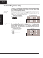
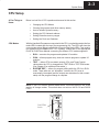
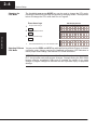
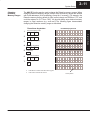
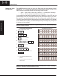
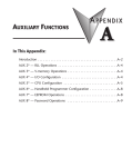
D2–HPP Setup 12 2–2 System Setup Handheld Programmer Setup This section provides information on some basic Handheld programmer features and characteristics. Regardless of which DL105 or DL205 PLC system you are using, the following operations will apply. Clearing the Display To begin a new function, it may be necessary to clear the Handheld programmer entry buffer and display screen. Pressing the CLR (clear) key will clear the buffer and display. You must press the CLR key several times to prepare for new entries. The CLR key does not delete instructions or data. Press these keystrokes System Setup 1. To clear entry buffer and display screen CLR S Using the Cursor CLR ... D2–HPP Display Example START OF STR X1 PROGRAM Repeat pressing CLR until display screen is blank. The always flashing J symbol indicates the current cursor position. You can move the cursor position by using the left or right arrow keys (²,³). The arrow left key performs just like the backspace key on a PC keyboard, deleting the character position contents. The figure below is a example how the display changes by pressing the left arrow key. Cursor position Press these keystrokes 1. To delete the previous character 2. To move cursor position right STRN X41 STRN X4 System Setup 2–3 CPU Setup A Few Things to Know Below is a brief list of CPU operations discussed in this section. CPU Modes With the Handheld Programmer connected to the CPU, you should examine the four mode LED’s located near the top of the programming unit. The LED’s will show the current mode status. Below is a definition for each of the Mode LED’s. Test mode is not supported by all DirectLOGIC PLC systems. Please refer to the appropriate DL105 or DL205 User Manual concerning the different CPU modes supported. RUN — executes the program and updates I/O modules. PGM — allows program entry, does not execute program or update I/O modules. TEST — allows CPU to maintain outputs, CRs, and Timer/Counter values when the CPU is changed from TEST-RUN to TEST-PGM mode. (See Chapter 6 for additional information.) RUNTIME EDIT — allows for program editing while the CPU is in RUN mode. These edits are not “bumpless.” Instead, the CPU scan is momentarily interrupted (and the outputs are maintained in their current state) until the program change is complete. NOTE: If your CPU has an external mode switch, it must be placed in the TERM position to change modes. This switch does not exist on the DL130 and DL230 CPU’s. System Setup Changing the CPU Modes Clearing the program (and other memory areas) How to initialize system memory Setting the CPU Network address Setting Retentive memory ranges Setting the Clock and Calendar 2–4 System Setup Changing the CPU Mode The Handheld programmer MODE key may be used to change the CPU mode. Pressing the MODE key will begin the process of changing modes. The keystrokes below will change the CPU mode from Run to Program. Press these keys 1. To begin Mode Change MODE 2. System Setup *MODE GO TO CHANGE* PGM MODE To select displayed mode ENT 3. HPP Display Results To accept mode change *MODE CHANGE* PGM MODE? ENT Use the NEXT/PREV keys to scroll available modes. *MODE CHANGE* CPU PGM Selecting Different You may use the PREV and NEXT key while performing a Mode Change, to choose a different mode. Always examine the Handheld programmer LED indicators to CPU Mode insure proper mode change, and desired CPU mode is selected. WARNING: Only authorized personnel, familiar with all equipment concerning the PLC, should make mode and program changes. Changes during the RUN mode become effective immediately. Make sure to consider the impact of any mode change or program changes to minimize the risk of personal injury or equipment damage. 2–5 System Setup I/O Configuration Automatic I/O Configuration (DL205 Only) The DL205 PLC system’s are designed to automatically examine installed I/O modules (including specialty modules) and establish the correct configuration and addressing when power is applied to the CPU. Slot 0 – 16pt Input Slot 1 – 8pt Input Slot 2 – Analog Input Slot 3 – 8pt Output Slot 4 – 8pt Relay Output Checking I/O Configuration The Handheld programmer may be used to view the current I/O configuration, by using the AUX 41 function. While connected to your PLC, use the following example to display your I/O configuration. Press these keystrokes 1. CLR 2. CLR CLR To display I/O configuration display B E 4 3. D2–HPP Display Results Clear complete display screen 1 AUX To check I/O information AUX AUX 4* 41 I/O CFG SHOW CFG ENT 4. Use arrow keys to display additional text 5. NEXT/PREV keys to view next and previous slots NEXT 6. /O BASE 0/SLOTB I/O BASE NEXT slot NEXT 7. AUX 41 I/O BASE D2–240: I/O BAS /O BASE P/S 0/SLOTP /O BASE CPU V 0/SLOTC #.# NEXT slot NEXT NEXT etc.. /O BASE 0/SLOT0 8PT Input MDL System Setup The I/O addresses are assigned using octal numbering, meaning the I/O numbering always starts at zero and does not include 8 or 9. For example, a 16 point input module located in slot zero (the first slot next to the CPU) would be labeled X0–X7 for the first 8 points and X10–X17 for the second 8 points (never using the number 8 or 9) The addresses are assigned in groups of 8 or 16, depending on the number of points for the I/O module. Please refer to the DL 205 User Manual for details on automatic addressing. The following diagram shows a DL205 example I/O scheme. 2–6 System Setup Auxiliary Functions What are Auxiliary Functions? Handheld programmer keypad contains a key labeled AUX, which allows you to perform various Auxiliary Functions. Auxiliary Functions are divided into several different categories. Some AUX functions are for the Handheld programmer itself, and others for the PLC system. If an error occurs while performing a auxiliary function, the CPU may be in the wrong mode, or invalid data may have been entered. System Setup Throughout this manual, step-by-step procedures for using Auxiliary functions are provided. Please refer to the DL105 or DL205 User Manual for details on AUX functions which may not be covered in this manual. AUX Function and Description DL130/ DL230 DL240 AUX 2* — RLL Operations AUX Function and Description DL130/ DL230 DL240 AUX 6* — Handheld Programmer Configuration 21 Check Program m m 61 Show Revision Numbers m m 22 Change Reference m m 62 Beeper On / Off HP HP 23 Clear Ladder Range m m 65 Run Self Diagnostics HP HP 24 Clear All Ladders m m AUX 3* — V-Memory Operations 31 Clear V Memory m AUX 7* — EEPROM Operations 71 Copy CPU memory to HPP EEPROM HP HP 72 Write HPP EEPROM to CPU HP HP 73 Compare CPU to HPP EEPROM HP HP m AUX 4* — I/O Configuration (DL205 CPU’s Only) 41 Show I/O Configuration m m 42 I/O Diagnostics m m 44 Power-up I/O Configuration Check m m 74 Blank Check (HPP EEPROM) HP HP 45 Select Configuration m m 75 Erase HPP EEPROM HP HP 76 Show EEPROM Type (CPU and HPP) HP HP AUX 5* — CPU Configuration 51 Modify Program Name m m 52 Display / Change Calendar m m 53 Display Scan Time m m 81 Modify Password m m 54 Initialize Scratchpad m m 82 Unlock CPU m m 55 Set Watchdog Timer m m 83 Lock CPU m m 56 Set CPU Network Address X m 57 Set Retentive Ranges X m 58 Test Operations X m 59 Bit Override X m 5B Counter Interface Configuration X m 5C Display Error / Message History X m AUX 8* — Password Operations m — supported 5 — not supported HP — Handheld Programmer function System Setup Handheld Programmer Diagnostics 2–7 The Handheld programmer has built–in self checking diagnostics. You can select the HPP Diagnostics with the AUX 65 function. When the diagnostic operation is finished, the main HPP diagnostic menu will be displayed. You may execute any of the Diagnostics by pressing the ENT key. The following example demonstrates using the D2–HPP Diagnotic operations. Press these keystrokes 1. CLR 2. CLR CLR Select the Diagnostic operation G F 6 5 AUX Run Diagnostic operation AUX AUX 6* 65 HPP RUN DIAG ENT 4. To continue with next Diagnostic operation NEXT 5. To run Diagnostic operation ENT 6. This diagnostic will flash the LCD display and all the LEDs. NEXT 7. AUX 65 RUN DIAG 1)KEYPAD CHECK? The EEPROM check will test the EEPROM installed in the handheld programmer. AUX 65 RUN DIAG 2)DISPLAY CHECK? AUX 65 RUN DIAG 3)LED&LCD CHECK? NEXT AUX 65 RUN DIAG 4)EEPROM CHECK? Press ENT to execute Diagnostic operation being displayed. Press CLR to exit the diagnostic operation being displayed. Beeper ON/OFF The Handheld programmer contains a beeper which sounds to confirm the operator keystrokes. This beeper may be toggled ON and OFF with the AUX 62 function. Press these keystrokes 1. CLR 2. D2–HPP display results Clear complete display screen CLR CLR To toggle beeper ON/OFF G C 6 2 AUX ENT AUX AUX 6* 62 CFG HPP BEEPER ON System Setup 3. D2–HPP display results Clear complete display screen 2–8 System Setup Clearing an Existing Program Important note, using this function will delete the PLC ladder program. With the CPU in Program mode, use the AUX 24 function to clear the entire PLC application program. Press these keystrokes 1. Clear complete display screen CLR CLR 2. CLR Select AUX 24 Clear Ladders display C E 2 3. D2–HPP Display Results 4 AUX To select Clear Ladders operation AUX AUX 2* 24 CLR ALL RLL CLR OPERA LAD A System Setup ENT 4. To clear all ladders LADDERS? ENT OK The PLC must be in Program mode. To clear specified range of ladder program, or V memory, use the following Auxiliary functions. Initializing System Memory AUX 23 — Clear Ladder Range AUX 31 — Clear V Memory Range The CPU setup and configuration data are stored in memory which is called Scratchpad Memory. The Scratchpad memory may require initializing if major changes are introduced to your PLC system configuration or setup. For example, if you specify a range of Control Relays (CRs) as retentive, this setup data will be stored in scratchpad memory. Basic program changes or loading new programs do not always demand that the Initialize Scratchpad function be executed. If required you may default Scratchpad memory with the AUX 54 function. NOTE: This function may change PLC setup and configuration data in your system. Press these keystrokes 1. CLR CLR 2. D2–HPP Display Results Clear complete display screen CLR Select AUX 54 Initialize Scratchpad F E 5 4 AUX 3. To select YES/NO option 4. To begin initialization AUX AUX 5* 54 AUX CLR 54 INIT SCRA XPAD YES/NO ENT Select NO option to exit without initializing. OK CPU CFG INIT SCRA System Setup Setting the CPU Network Address 2–9 Some CPU’s, such as the DL240, contain a built-in Direct NET port (PORT2). The Handheld programmer may be used to set the Port 2 network address and parameters. The default parameter settings are: Station address 1 HEX mode (the handheld programmer will only support HEX mode) Odd parity 9600 baud rate The Direct NET User Manual provides additional information about network and communication parameter settings. The following example demonstrates how to use the AUX 56 function. 1. CLR CLR To select the diagnostic operation F G 5 3. D2–HPP Display Results Clear complete display CLR 2. System Setup Press these keystrokes 6 AUX To change the network address AUX AUX 5* 56 CPU CPU CFG N/W A AUX N/W 56 # CPU 01 N/W A AUX N/W 56 # CPU 01 N/W A 02 AUX HEX 56 CPU N/W / ASCII ENT 4. Type new address number 5. To save the newly entered address 1–90 ENT 6. 7. To select communications mode use arrow keys to move cursor position To save communications mode ENT 8. To select communications parity 9. To save communications parity ENT 10. AUX 56 NONE / A CPU ODD N/W A AUX 56 CPU 9600/19.2 N/W A AUX OK N/W A To select communications parity Press the CLR key to exit the AUX 56 function. Shaded box indicates cursor position. 56 CPU 2–10 System Setup Retentive Memory Ranges The DL105 and DL205 CPU’s all contain Retentive memory. Retentive memory is memory ranges which may store information in case of power loss. A super capacitor will maintain latest register values in case of short period CPU power loss or failure. If retentive memory ranges are important in your application, make sure to install a optional backup battery. Battery installation is covered in appropriate DL105 and DL205 User Manuals. Factory defaults for Retentive memory ranges are suitable for most applications. To change Retentive memory range, use AUX 57 to select and set the desired range. The table below lists the Retentive memory factory defaults for the DL105 and DL205 CPU’s. System Setup DL130 Memory Area Default Range Available Range Control Relays C300 – C377 C0 – C377 V Memory V2000 – V2377 V0 – V7777 Timers None by default T0 – T77 Counters CT0 – CT77 Stages None by default S0 – S377 CT0 – CT77 DL230 Memory Area Default Range Available Range Control Relays C300 – C377 C0 – C377 V Memory V2000 – V2377 V0 – V7777 Timers None by default T0 – T77 Counters CT0 – CT77 Stages None by default S0 – S377 CT0 – CT77 DL240 Memory Area Default Range Available Range Control Relays C300 – C377 C0 – C377 V Memory V2000 – V7777 V0 – V7777 Timers None by default T0 – T177 Counters CT0 – CT177 Stages None by default S0 – S777 CT0 – CT177 System Setup Changing Retentive Memory Ranges 2–11 The AUX 57 function may be used to change the Retentive memory ranges. When changing Retentive Memory ranges, keep in mind all memory ranges are defined with Octal addresses (8 bit boundaries, except for V–memory). For example, the Retentive memory factory default for CRs (control relays) are C300 thru C377, and could be reduced to C177 thru C300. You should always enter desired memory ranges in Octal numbers (e.g. xxx0–xxx7).The following figure demonstrates changing the Retentive memory range as described. Press these keystrokes 1. Clear entire display screen CLR CLR Select AUX 57 function F H 5 3. CLR 7 AUX To change memory range AUX AUX 5* 57 CPU RET CFG RANGE AUX 1st 57 RET C0300 RANGE AUX 1st 57 RET C0300 RANGE 177 AUX END 57 RET C0377 RANGE 300 AUX 1ST 57 RET V02000 RANGE ENT 4. Enter new start address B H 1 5. H 7 7 Accept entry ENT 6. Enter new end address D A 3 7. A 0 0 Accept entry ENT Press ENT to continue with other memory types. Press CLR to exit AUX 57 function. Cursor position System Setup 2. D2–HPP Display Results 2–12 System Setup System Setup Setting the Clock and Calendar The AUX 52 function allows you to set the Real–time clock and calender. Not all DirectLogic PLC’s support the hardware clock and calender feature. For the CPU’s which feature a clock and calendar the following format is used. Date — Year, Month, Date, Day of week (0 – 6, Sunday thru Saturday) Time — 24 hour format, Hours, Minutes, Seconds If you change the date without updating the day of week (0–6), the CPU will not automatically correct any discrepancy between the date and the day of the week. For example, if you change the date to the 15th of the month and the 15th is on a Thursday, you will also have to change the day of the week (unless the CPU already shows the date as Thursday). Use the following example to change any component of the date or time settings. NOTE: Verify the clock and calender is supported by your CPU, before attempting to use this Auxiliary function. Press these keystrokes 1. Clear complete display screen CLR 2. CLR Select AUX 57 F C 5 3. D2–HPP Display Results 2 AUX AUX AUX 5* 52 CPU CFG CALENDER Select date and clock display ENT 4. A C 0 5. ENT Enter new time if required B C 1 7. 2 To accept press ENT twice ENT 6. AUX 52 CALENDAR 96/01/01/6(SAT) Enter new date if required D 2 A 3 0 AUX 52 CALENDAR 96/01/02/7(SUN) AUX 52 CALENDAR TIME 00:06:00 To accept new entry press ENT twice ENT ENT The shaded area indicates cursor position. Press the CLR key to exit date and AUX 52 CALENDAR TIME 12:30:00 96/01/02 12:30:15 clock function. NOTE: If the CPU is without power for an extended period of time a battery is required to maintain the proper date and time.