1
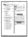
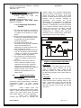
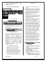
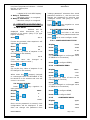
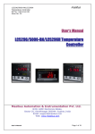
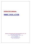
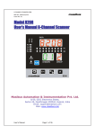
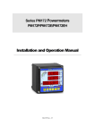
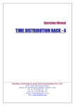
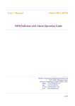
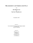
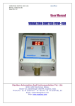
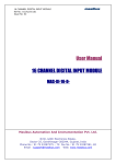
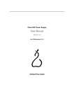
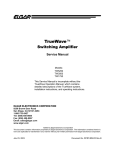
Low Cost Temperature Indicator – LI4248
Ref No: m73H/om/101
Issue No: 02
masibus
Operator’s Manual
Low Cost Temperature Indicator
Masibus Automation And Instrumentation Pvt. Ltd.
B/30, GIDC Electronics Estate,
Sector-25, Gandhinagar-382044, Gujarat, India.
Ph: 91 79 23287275-79
Fax: 91 79 23287281/82
Email: [email protected]
Web: www.masibus.com
masibus
Low Cost Temperature Indicator – LI4248
Ref No: m73H/om/101
Issue No: 02
Contents
(1)INTRODUCTION
(02)
1.1 Purpose of the Manual
1.2 Product over View / Description
1.3 Product Ordering Code
1.4 List of Accessories
(2) SAFETY / WARNING
PRECAUTIONS
2.1 Safety Precautions
2.2 Warning Precautions
(03)
(3) SPECIFICATIONS
(03)
3.1: Displays
3.2: Inputs
3.3: Input Range
3.4: Accuracy
3.5: Output
3.6: Calibration
3.7: Types of Set points
3.8: Power Supply
3.9: Environmental condition
(4) INSTALLATION GUIDELINES(04)
4.1 MOUNTING DETAILS
4.2 TERMINAL CONNECTION
4.3 FRONT PANEL DESCRIPTION
(5) OPERATION GUIDELINE
(06)
5.1 RUN MODE
5.2 PASSWORD MODE
5.3 CONFIGURATION MODE
5.3.1: Configure Input Type
5.3.2: Configure Zero
5.3.3: Configure Span
5.3.4: Configure Set point Type-1
5.3.5: Configure Hysteresis-1
5.3.6: Configure Set point Type-2
5.3.7: Configure Hysteresis-2
5.3.8: Configure Open Sensor
5.3.9: Configure Decimal Point
5.3.10: Configure Brightness
5.3.11: Configure Password
5.4 CALIBRATION MODE
5.4.1: Calibration of Ambient
5.4.2: Calibration of Zero
5.4.3: Calibration of Span
User’s Manual
(6) Maintenance
(09)
Figures
Figure
Figure
Figure
Figure
Note:
1:
2:
3:
4:
Typical Relay Operation
Mounting Details
Terminal Connections
Details of Front Panel
(02)
(04)
(05)
(05)
Information in this manual is
subject to change without prior
notice or permission.
WARNING SYMBOL
The symbol calls
attention to the operating procedure,
practice or the like which if not correctly
performed or adhered to , could result in
personal injury or damage to or
destruction of part or all of the product
and system. Do not proceed beyond a
warning symbol until the indicated
condition are fully understood and met.
CLASS-2 TYPE OF
INSTRUMENT
Note: Class-2 – Instrument is using
Line & Neutral for Power Supply
Input.
Page 1 of 8
masibus
Low Cost Temperature Indicator – LI4248
Ref No: m73H/om/101
Issue No: 02
1. INTRODUCTION
1.1. Purpose of the Manual:
1.1.1.
How
to
read
this
manual???
Installer: Read Chapters 1, 4, 5
System Designer and New User:
Read All Chapters
1.1.2. Regarding This User’s
Manual
→ This manual should be provided to
the end user. Keep an extra copy
or copies of the manual in a safe
place.
→ Read this manual carefully to gain
a thorough understanding of how
to operate this product before
starting operation.
→ This manual describes the
functions of this product. Masibus
does not guarantee the
application of these functions for
any particular purpose.
→ Under absolutely no circumstances
may the contents of this manual,
in part or in whole, be transcribed
or copied without permission.
→ The contents of this manual are
subject to change without prior
notice.
→ Every effort has been made to
ensure that the details of this
manual are accurate. However,
should any errors be found or
important information be omitted,
please contact your nearest
Masibus representative or our
sales office.
Product over View /
1.2.
Description:
Model LI4248 is a micro
controller based Temperature Indicator,
incorporate bright, 4 Digit Seven
Segment Display indicating process
value.
Relay output from the
instrument will have output state either
“ON” or “OFF” depending on PV (process
value), set point value and set point
type. Refer figure 1 for relay operation.
Since
the
temperature
crosses the set point to change the
User’s Manual
output stage, the process temperature
will be cycling continuously, going from
below set point to above, and back
below. In cases where this cycling occurs
rapidly, and to prevent damage to
contactors and valves, an on-off
differential, or “hysteresis,” is added to
the controller operations. This hysteresis
assures, if temperature exceed set point
by a certain amount before then only
output will turn off or on again. On-Off
hysteresis prevents the output from
“chattering” or making fast, continual
switches if the cycling above and below
the set point occurs very rapidly.
Figure 1: Typical Relay operation
High type:
For High type of set value,
once process value reaches up to set
point + Hysteresis value, relay will be
ON after nearly 1.5 seconds and it will
be ON until process value goes down to
Set point.
Low type:
For Low type of set value,
once process value reaches down to set
point - Hysteresis value relay will be ON
after nearly 1.5 seconds and it will be
ON until process value goes up toward
Set point.
Page 2 of 9
Low Cost Temperature Indicator – LI4248
Ref No: m73H/om/101
Issue No: 02
1.3 Product Ordering Code:
Model LI4248
Input Types
Relay
X
X
1
J(W/1ºC)
S
One
2
J(W/0.1ºC)
D
Two
3
4
K(W/1ºC)
K(W/0.1ºC)
PT-100,
3W
4-20 mA
0-20 mA
1-5 VDC
0-5 VDC
9
C
D
E
F
Aux Power
Supply
XX
85-265
U1
VAC
18U2
30VDC
Mounting
Aux output
XX
PO
X
Panel
N
None
2
TPS24VDC
X = Specify from table
1.4 List Of Accessories:
Sr. No.
1
Description
Of Accessories
Mounting Clamps
Quantity
02
Mounting clamps should be of proper
length and type according to the module
of instrument.
2. SAFETY / WARNING
PRECAUTIONS
2.1. Safety Precautions:
Dangerous voltages capable of causing
death are sometimes present in this
instrument.
Before
installation
or
beginning
of
any
troubleshooting
procedures the power to all equipment
must be switched off and isolated. Units
suspected of being faulty must be
disconnected and removed first and
brought
to
a
properly
equipped
workshop for
testing
and repair.
Component replacement and interval
adjustments must be made by a
company person only.
2.2. Warning Precautions:
→ Before wiring, verify the label for
correct model no. and options.
→ Wiring must be carried out by
personnel, who have basic electrical
knowledge and practical experience.
→ It is recommended that power of
these units to be protected by fuses,
circuit breakers or external over
User’s Manual
masibus
current rated at the minimum value
possible.
→ All wiring must confirm to appropriate
standards of good practice and local
codes and regulations. Wiring must
be suitable for voltage, current, and
temperature rating of the system.
→ Beware not to over-tighten the
terminal screws.
→ Unused control terminals should not
be used as jumper points as they may
be internally connected, causing
damage to the unit.
→ Verify that the ratings of the output
devices and the inputs as specified in
Chapter 7 are not exceeded.
→ Upon receipt of the shipment remove
the unit from the carton and inspect
the unit for shipping damage. If any
damage due to transit, report and
claim with the carrier. Write down the
model number and serial number for
future reference when corresponding
with our Customer Support Division.
→ Do not use this instrument in areas
such as excessive shock, vibration,
dirt, moisture, corrosive gases or
rain. The ambient temperature of the
areas should not exceed the
maximum rating specified.
→ Provide power from a single-phase
instrument power supply. If there is a
lot of noise in the power line, insert
an insulating transformer into the
primary side of the line and use a line
filter on the secondary side. As
counter measures against noise, do
not place the primary and secondary
power cables close to each other.
3. SPECIFICATION
3.1 DISPLAYS:
• Process Value and Parameter
display:
4 digits 0.56" Seven Segment
Red LED’s For Process Variable in
degree Celsius.
• Status Display: Individual
discrete Red LED’s to Indicate relay
status.
• Operation Keys: INC, DEC (For
increment and decrement of
various parameters and setpoint).
Page 3 of 9
masibus
Low Cost Temperature Indicator – LI4248
Ref No: m73H/om/101
Issue No: 02
SET1 and SET2(set parameters
and setpoints).
3.2 INPUTS:
•
•
•
•
•
•
•
•
•
•
RTD - PT100 3-wire, PT-100
(0.1ºC)(Automatic 3 wire
compensation)
Thermo-couple types J, K, J
(0.1ºC), K(0.1ºC) (ANSI
standard)
4-20mA/1-5 V dc linear
0-20mA/0-5 V dc linear
Burn out Current : 0.25 uA
CMRR : > 120dB
NMRR : > 40dB
Input Impedance : > 1MΩ
Resolution : 15 bits
Sampling Period : 55mS
3.3 INPUT RANGE:
PT100
:-200 to 850 ºC
PT100 (0.1ºC) :-199.9 to 850.0 ºC
J
:-200 to 1200ºC
K
:-200 to 1372ºC
J, K (0.1ºC)
:-199.9 to 999.9ºC
4-20mA/1-5VDC, 0-20mA/05VDC:-1999 to 9999 (Field Scalable)
(For Current Input Use
Resistor 250Ω 0.1%
Externally).
3.4 ACCURACY:
•
Linear:
±*0.25 % Full Span ± 1 Count
•
RTD ,T/C:
For >0°C ±*0.25% Full Span ± 1
Degree
For <0°C ±*0.5% Full Span ± 1
Degree
3.5 OUTPUT:
•
•
3.6 CALIBRATION:
•
Zero and Span calibration for
input using front panel keypad.
•
CJC for T/C type input and 3wire lead compensation for RTD
sensor is automatic.
•
Instrument
Warm-up
Time
approx. 30 Min.
* Change of Input type is Subject
to recalibration.
3.7 TYPES OF SET POINT:
•
Set point types are configurable
to energize relays for actual value
below or above set point with delay
time for individual Relay.
•
Hysteresis setting 0 to 100
Counts.
3.8 POWER SUPPLY:
•
•
Operating Supply:
85-265VAC @ 50Hz / 120-290
VDC
Or 18-30VDC(optional)
Power consumption:
< 5VA
3.9 ENVIRONMENTAL
CONDITION:
• Insulation Resistance:
>200MΩ @ 500VDC
• Molding type: ABS Plastic
• Weight: 187 Gms.
• Ambient Temperature: 0 to 55 °C
• Humidity: 30 to 95% RH noncondensing
• Storage Temperature: 0-80 °C
4. INSTALLATION
GUIDELINE
4.1 Mounting Details
Relay O/P(Optional):
Rating: 2A/230VAC
Life cycle Mechanical: 105 times
Life Cycle Electrical: 105 times
TPS: +24VDC + 5% @ 30mA
User’s Manual
Page 4 of 9
masibus
Low Cost Temperature Indicator – LI4248
Ref No: m73H/om/101
Issue No: 02
Figure 2: Mounting Details
FRONT BEZEL: 48 x 96 mm
PANEL CUTOUT: 92+0.8 x 45+0.8 mm
DEPTH BEHIND THE PANEL: 75mm
Note:
UNPACKING: Upon receipt of
the shipment remove the unit form
the carton and inspect the unit for
shipping damage. If any damage
due to transit, report and claim with
the carrier. Write down the model
number, serial number, and date
code for future reference, when
communicating with our Customer
Support Division.
Use external switch or circuit
breaker and external over current
protection devices to protect whole
panel or instrument in hazardous
condition.
Power Supply Input(85-265VAC
@ 50Hz /120-290VDC).
Note:
a. Use>250V-1Amp Cable for Power
Supply.
b. If cable has two parallel wires inside
then Isolation between the wires
should be 2.5 KV.
2. Terminal 11 & 12 & 13:
For Relay-1 potential free
Contacts (Use 230V -2A load)
3. Terminal 14 & 15 & 16:
For Relay-2 potential free
Contacts (Use 230V -2A load)
4. Terminal 1:
+24V Transmitted power supply
Output and the respective
ground is given on Terminal number.
5. Terminal 2:
For RTD Input Only
6. Terminal 3 & 4:
For T/C & Linear Input (For
Current Input – Use Resistor 250Ω 0.1%
externally).
4.3 FRONT PANEL DESCRIPTION
Do not use this instrument in
areas such as excessive shock,
vibration, dirt, moisture, corrosive
gases
or
rain.
The
ambient
temperature of the areas should not
exceed
the
maximum
rating
specified.
4.2 Terminal Connection
Figure 4: Details of Front Panel
1. Ent Key:
- By pressing incrementDecrement key,
Increment & Decrement value
in PV window respectively.
- On pressing ENT Key, the
Respective value is stored and
Displayed on PV window in
CONF, PROG and CAL mode.
2. Increment key
Figure 3: Terminal connection
1. Terminal 9 & 10:
User’s Manual
& Decrement
:
-On pressing this both key Shows
PASS in PV windows.
3. PV window:
Key
Page 5 of 9
masibus
Low Cost Temperature Indicator – LI4248
Ref No: m73H/om/101
Issue No: 02
- 4 digital 0.56 inch RED Display.
4. Relay-1 Indication:
- ON when relay-1 is energized.
5. Relay-2 Indication:
- ON when relay-2 is energized.
“change password” submenu then initial
password would be 1, else the user can
change the password by entering into
“configure mode” and going to “pass”
submenu.
Key together to come
Press
out of password mode.
5. OPERATION GUIDELINE
5.1 Run Mode:
5.3 CONFIGURATION MODE
Ambient will be
displayed when decrement key is
pressed in run mode. (Only if T/C type
input is selected).
and then it will show
Press
“PASS”, enter correct password and then
Press
press
30.0
if enter key pressed, then setpoint-1 will
appear on PV window.
Press
st-1
Press
OR
00
(By inc/dcr key value of setpoint-1 can
be changed in PV window)
Press
st-2
(This will save the changed
unchanged setpoint1 value.)
Press
key to enter configure mode.
5.3.1 CONFIGURE INPUT TYPE
Display
ConF
Press
InPt
Press
OR
K.tC
Press
InPt
(To save changed or unchanged value
of ZERO as in PV window)
or
OR
Press
to configure ZERO,
200
5.3.2 CONFIGURE ZERO
(By inc/dcr key value of setpoint-2 can
be changed in PV window)
Display
zErO
Press
pressed, changed
When enter key
or unchanged value of SETPOINT-2 will
be saved as in PV window and unit will
come in run mode.
5.2 Password Mode:
Key together to
Press
enter password mode.
PASS.
Display
Press
Press
OR
Press
Press
OR
-150
(By inc/dcr key value of zero can be
changed in PV window)
zErO
Press
(To save changed or unchanged value
of ZERO as in PV window)
Press
to configure SPAN,
0
Press
to configure INPT
1
5.3.3
ConF
Once correct password is entered, then
configuration will be displayed. if user
does not change the password from
User’s Manual
-100
CONFIGURE SPAN
Display
span
Press
1200
Press
OR
1372
Page 6 of 9
masibus
Low Cost Temperature Indicator – LI4248
Ref No: m73H/om/101
Issue No: 02
(By inc/dcr key value of span can be
changed in PV window)
SPAN
Press
(To save changed or unchanged
value of SPAN as in PV window)
Press
to configure SET
POINT1 type, Press
ZERO
to configure
5.3.4 CONFIGURE SET POINT1
TYPE
tSP1
Display
Press
Press
OR
Press
tSP2
(To save changed or unchanged value of
SETPOINT-2 type as in PV window)
Press
to configure Hysteresis-2,
Press
to configure Hysteresis-1
5.3.7 TO SET VALUE OF
HYSTERESIS 2
Display
Hy-2.
H on
Press
10
L on
Press
(By inc/dcr key value of setpoint-1 can be changed
in PV window)
Press
(By inc/dcr key value of setpoint-2 can be changed
in PV window)
tSP1
(To save changed or unchanged value of
SETPOINT-1 type as in PV window)
OR
20
(By inc/dcr key value of hysteresis -1
can be changed in PV window)
Press
(To save changed or unchanged
HYSTERESIS-1 as in PV window)
Hy-2.
value
Press
to configure Hysteresis-1,
Press
to configure open sensor,
Press
to configure SPAN
Press
to configure setpoint2 type
5.3.5
Press
Press
5.3.8 CONFIGURE OPEN SENSOR
TO SET VALUE OF
HYSTERESIS 1
Display
OR
Press
Hy-1.
Press
10
Press
20
Hy-1.
value
of
Press
to configure setpoint-1 type
Display
Press
OR
User’s Manual
dn
dn
(To save changed or unchanged value of Open
sensor as in PV window)
Up scale: Under Open condition PV is
treated above set point.
Down scale: Under Open Condition PV
is treated below set point.
H on
Table-1:
Relay type
PV
Hi-On
PV > SP
PV < SP
Open sensor
Up scale
Down scale
L on
Low-On
SET
tSP2
Press
OR
Press
to configure setpoint-2 type,
CONFIGURE
POINT2 TYPE
UP
(By inc/dcr key value of open sensor can be
changed in PV window)
Press
5.3.6
OPES.
Display
(By inc/dcr key value of hysteresis -1
can be changed in PV window)
(To save changed or unchanged
HYSTERESIS-1 as in PV window)
of
PV > SP
PV < SP
Relay
On
Off
On
Off
Led
On
Off
On
Off
Off
On
Off
On
Page 7 of 9
masibus
Low Cost Temperature Indicator – LI4248
Ref No: m73H/om/101
Issue No: 02
Open sensor
Up scale
Off
Down scale
On
Where SP = Set Point.
PV = Process value
Off
On
Press
5.3.9
POINT
Display
to configure Hysteresis-2.
CONFIGURE
dP
000.0
OR
00.00
(By inc/dcr key value of decimal point can be
changed in PV and PV window)
Press
dP
(To save changed or unchanged value of
DECIMAL POINT as in PV and PV window)
Press
to configure Brightness,
Press
to configure OPENSENSOR,
Note:
1. Decimal Point is only available
with 0-5V (0-20mA) or 1-5V (420mA) input.
5.3.10 CONFIGURE BRIGHTNESS
Display
BRhT
Press
10
Press
OR
50
(By inc/dcr key value of brightness can be changed
in PV window)
Press
50
(To save changed or unchanged value of
BRIHTNESS as in PV window)
Press
to configure DP (if linear
input type) or open sensor
Press
OR
1
(By inc/dcr key value of password can be changed
in PV window)
Press
1
(To save changed or unchanged value of
password as in PV window)
Press
to configure BRIGHTNESS.
to configure PASSWORD,
Key together to come
Press
out of configuration mode.
Press
in run mode.
5.4
Here
5.3.11 CONFIGURE PASSWORD
Key together to enter
CALIBRATION MODE
one-shot
calibration
is
and then
implemented. Press
it will show “PASS” i.e. password mode,
enter correct password and then press
and then
calibration mode.
Key
to
enter
5.4.1 CALIBRATION AMBIENT
Display
Cal
Press
Amb
Press
30.0
Press
OR
31.0
(By inc/dcr key value of ambient can
be changed in PV window)
Press
Amb
(To save changed or unchanged value of
AMBIENT as in PV window)
Press
to configure ZERO,
5.4.2 CALIBRATION OF ZERO
Display
CALZ
-099
Press
Press
User’s Manual
0
DECIMAL
Press
Press
Press
Press
to configure BRIGHTNESS
Press
(If linear input type is not selected)
or DP (If linear input type is
selected)
PASS.
Display
OR
(By inc/dcr key value of calz can
be changed in PV window)
Page 8 of 9
-100
masibus
Low Cost Temperature Indicator – LI4248
Ref No: m73H/om/101
Issue No: 02
Press
CALZ
(To save changed or unchanged value of
CALZ as in PV window)
Press
Press
to calibrate SPAN,
Press
Press
to configure AMB,
Note:
5.4.3 CALIBRATION OF SPAN
Display
CALS
Press
Press
1099
OR
CALS
(To save changed or unchanged value of
CALS as in PV window)
to configure ZERO,
1.Amb calibration is only available
with J,K - T/C input.
Press
calibration mode.
Key together to come out of
1200
(By inc/dcr key value of cals can
be changed in PV window)
6
Maintenance:
As a precautionary step, please switch off the units before
troubleshooting. Disconnect the Unit suspected of being faulty and bring it to
workshop for testing and repair. Component replacement or any other change
must be made by a company person only.
User’s Manual
Page 9 of 9