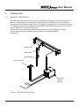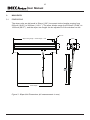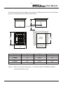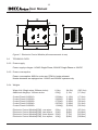
1
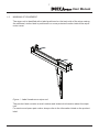
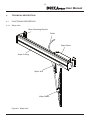
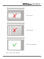
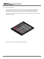
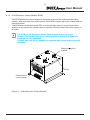
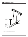
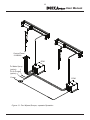
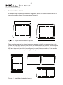
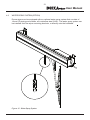
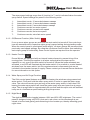
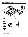
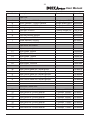
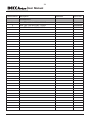
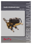
User Manual
DECCA
Heavy Duty Straight Line Wipers
Odin Control System
www.deccawiper.com
DOCUMENT FRONT SHEET
USER MANUAL
0
Initial release
05.09.2011
Indok
Rev.
Reason for issue
Date
Prepared
BS
Controlled
Approved
Released
Postal address: Decca Wiper Systems AS, Espehaugen 25, N-5028 Blomsterdalen, Norway
Telephone. (Int. +47) 55 11 23 00 - Telefax (Int. +47) 55 11 23 01
[email protected] www.deccawiper.com
5
User Manual
Contents
1INTRODUCTION
1.1 PURPOSE OF MANUAL
1.2 MARKING OF EQUIPMENT
1.3SYMBOLS
1.4 COMMON ABBREVIATIONS
6
6
7
8
8
2INTRODUCTION
2.1 GENERAL DESCRIPTION
9
9
3
MAIN DATA
3.1DIMENSIONS
3.2 TECHNICAL DATA
3.2.2 POWER SUPPLY
3.2.3 POWER CONSUMPTION
3.2.4 WEIGHTS
10
10
12
12
12
12
4TECHNICAL DESCRIPTION
4.1 FUNCTIONAL DESCRIPTION
4.1.1 WIPER UNIT
4.1.2
WIPER ARMS
4.1.3 ODIN CONTROL PANELS
4.1.4 ODIN ELECTRONIC CONTROL MODULE (ECM)
4.2 TYPICAL INSTALLATIONS
4.3 WATER SPRAY SYSTEM (OPTION)
4.3.1 AIR PURGE SYSTEM
13
13
13
14
16
17
20
21
22
5
5.1
5.2
5.3
5.4
5.4.1
5.4.2
5.4.3
INSTALLATION PROCEDURE
LOCATION OF WIPER UNIT BRACKETS
BULKHEAD PENETRATION
WIPER CASING
CABLE CONNECTIONS WIPER UNIT CABLE CONNECTON
ELECTRONIC CONTROL MODULE(ECM) CABLE CONNECTION WIPER CONTROL PANEL
23
23
24
24
25
25
26
27
6
6.1
6.1.1
6.1.2
6.1.3
6.1.4
6.1.5
SYSTEM OPERATION
WIPER CONTROL PANEL
WIPER SPEED SETTINGS
OFF/RESUME FUNCTION (MAIN SWITCH) HEATER FUNCTION WATER SPRAY AND AIR PURGE FUNCTION NIGHT MODE 30
30
30
31
31
31
31
7
SPARE PARTS
8WARRANTY
32
9DRAWINGS
37
36
6
User Manual
1INTRODUCTION
1.1
PURPOSE OF MANUAL
The purpose of this manual is to provide guidance for installation and operation of
Decca Straight Line Wipers controlled with the Odin Control system, as supplied
by Decca Wiper Systems AS.
The manual is intended to give technical information to understand the functions and
features of the Decca Wiper Systems and to be able to operate the system, together
with installation, commissioning and maintenance information.
The manual shall also be used as a textbook for training of crew, and should be read and understood before operation of the wiper system.
Changes occuring since the last issue of the manual are marked with vertical black lines
in left margin.
7
User Manual
1.2
Marking of Equipment
The wiper unit is identified with a label positioned on the back side of the wiper casing.
An additional, similar label is positioned in a more protected location behind the wiper
motor cover.
Figure 1 - Label Locations on wiper unit
The product label contains a serial number and technical information about the wiper
unit.
For service and spare part orders, always refer to the information listed on the product
label.
8
User Manual
1.3SYMBOLS
1.4
The NOTE symbol gives clarifying information or
special instructions which are crucial for the equipment or to the
operation performed.
The WARNING symbol gives clarifying information or
special instructions where personal injuries or damage to the equipment
can occur.
COMMON ABBREVIATIONS
Abbreviation
mm
"
kg
ECM
Explanation
- millimetres
-inches
- kilogram
-
Electronic Control Module
9
User Manual
2Introduction
2.1
General description
Modern shipbuilding takes full account of visibility requirements. Larger wheelhouses with an omnidirectional view are part of this trend. As a result, there is an increase in
window area that must be kept clear in all weather conditions. Decca straight line wipers are designed to meet these demands with reliable and efficient operation in heavy rain, storm conditions, sleet and even snow.
With unique technical design features and built with only high quality materials,
Decca wipers provide a reliable wiper operation in extreme weather
conditions.
Wiper Unit
Wiper Arm
Wiper Blade
Control Panel
Electronic
Control
Module
Figure 2 - Example of wiper system
10
User Manual
3main data
3.1Dimensions
The wiper units are delivered in 50mm (1,96”) increment stroke lengths ranging from
500mm (16,69”) to 3000mm (118,11”). The wiper blades range from 500mm (19.68”) to
1000mm (39.37”), and the wiper arm length can be adjusted to fit the window on site.
Ø9.5 x8
Wiper casing length = Stroke length + 210
27
183.8
55
175
105
105
Stroke length
Figure 3 - Wiper Unit Dimensions (all measurements in mm)
200
164
11
User Manual
The Odin Control Panel is available in five versions, featuring control of one to five wiper
groups. See figure below for physical dimensions.
73
A
50 free space
114
Panel
cut out
138
C +/- 1.5
B
Model
12183010
12183020
12183030
12183040
12183050
116
+/- 1.5
A
49
73
96
119
151
B
80,5
103.4
126.9
150.4
182.5
C
51
75
98
121
153
Figure 4 - Odin Control Panel dimensions - Three Group Panel (1283030) illustrated
(all measurements in mm)
12
User Manual
Figure 5 - Electronic Control Module (all measurements in mm)
3.2technical data
3.2.2 Power supply
Power supply voltages:110VAC Single Phase, 220VAC Single Phase or 24V DC
3.2.3 Power consumption
Power consumption: 90W for motor and 75W for heater element
Heater elements are equipped on 110VAC and 220VAC systems only
3.2.4 Weights
Wiper Unit (Single wiper 500mm stroke): Additional weight pr. 100mm stroke:
11,0kg 0,5kg (24,2lb) (1,1lb) (387.2oz)
(17,6oz)
Control Panel 12183010:
Control Panel 12183020:
Control Panel 12183030:
Control Panel 12183040:
Control Panel 12183050:
0,500kg 0,625kg 0,750kg 0,875kg 1,000kg (1,10lb) (1,38lb) (1,65lb) (1,93lb) (2,20lb) (17,6oz)
(21,0oz)
(26,4oz)
(31,8oz)
(35,2oz)
Electronic Control Module(ECM), one wiper:
Electronic Control Module(ECM), two wipers:
Electronic Control Module(ECM), three wipers:
Electronic Control Module(ECM), four wipers:
2,5kg 3,0kg 3,5kg 4,0kg (5,5lb) (6,6lb)
(7,7lb)
(8,8lb)
(87,0oz)
(104,6oz)
(122,2oz)
(139,8oz)
13
User Manual
4
technical description
4.1
Functional description
4.1.1 Wiper Unit
Wiper Mounting Bracket
Cable
Wiper Motor
Wiper Casing
Wiper Arm
Wiper Blade
Figure 6 - Wiper Unit
14
User Manual
Figure 7 - Wiper Function - as viewed from front of wiper unit
4.1.2
Wiper Arms
The arm is supplied in full length, and is cut
to appropriate length on site.
The three M4 DIN912 bolts on the upper
part of the arm assy secure the arm in
correct position.
This mechanism allows +/- 30mm fine
adjustment of the arm length.
The wiper arm features step less spring
tension adjustment by means of two
springs and a spring tension clamp that
is secured by two M4 DIN912 bolts.
Tension Springs
The spring tension clamp should be
positioned so that the wiper blade is
pressed against the window with
a force of approximately 2 kg (4 lb).
See figure 9 for practical advice on
spring tension adjustment.
Spring Tension
Clamp
Figure 8 - Wiper Arm
15
User Manual
Tension too low
Tension too high
Tension correctly adjusted
Figure 9 - Wiper Tension Adjustment
16
User Manual
4.1.3 Odin Control Panels
The wiper system is operated from the control panel, typically mounted with good
access from the operator’s position. From the control panel the wiper/groups are
switched on and off, and the wiper speed and intermittent settings are adjusted.
The Odin control panel is available in five versions, controlling from one to five different
wipers/wiper groups.
Figure 10 - Odin Control Panel (12183030 illustrated)
17
User Manual
4.1.4 Odin Electronic Control Module (ECM)
The ECM distributes control signals to the wiper units and the optional water spray
system, with input from the control panel. Each ECM controls up to four wipers and two
solenoid valves.
The ECM has a protection grade IP20, and should be located in a well vented area
where it is not exposed to excess dust or moisture. Allow at least 50mm free space on
all sides.
The ECM should be placed where there is good access for future
service. Placing the ECM above ceiling panels or below floor panels is
therefore not recommended.
Consult with your Decca supplier for practical advice and project specific solutions.”
Cable connection
to wiper
Fuse
Connection to
control panel
Figure 11 - Odin Electronic Control Module
18
User Manual
Control Panel
12183010
To Water Spray
(option)
To Air Purge
(option)
Power
Figure 12 - Typical set up, one Wiper/Group
ECM
19
User Manual
Control Panel
12183020
ECM
To Water Spray
(option)
To Air Purge
(option)
Power
Figure 13 - Two Wipers/Groups, separate Operation
ECM
20
User Manual
4.2
Typical installations
A standard wiper installation features a single arm wiper unit that is mounted above or
below the window frame. See examples in figure 14.
Figure 14 - Single Wiper Installation Layouts
Taller windows require two wipers to ensure maximum visibility, where one wiper unit
covers the upper part and the other covers the lower part of the window. See example in
figure 15, left side. Optionally, the wiper unit can be supplied with two wiper arms. The
dual arm wiper unit can either be configured to cover one large window, or two smaller
adjacent windows. See examples in figure 15, right side.
Figure 15 - Dual Wiper Installation Layouts
21
User Manual
4.3
Water Spray System (option)
Decca wipers can be equipped with an optional water spray system that consists of
12mm OD piping and nozzles, all in stainless steel (316L). The water spray system can
be installed onto the wiper mounting brackets, or directly onto the bulkhead.
Figure 16 - Water Spray System
22
User Manual
4.3.1 Air Purge System
To prevent trapped water from freezing inside the water spray piping at sub zero
temperatures, the Decca wipers can be equipped with an air purge system.
The system comprises two solenoid valves and an electronic valve controller with a
programmable timer function incorporated in the ECM. Air is supplied from the ship’s
compressed air system.
Water
Air
Control Panel
12183010
ECM
Power
Figure 17 - Water Spray System with Air Purge
23
User Manual
5installation procedure
Location of Wiper unit brackets
The wiper unit is equipped with two fixing brackets. The brackets can either be
welded or bolted to the bulkhead. Note that the standard brackets are made of
aluminium, but mild steel brackets can be ordered as an option.
Check the distance between the mounting holes on the end covers of the wiper
unit compared with measurements given in Figure 18.
The wiper casing should be placed as close to the window frame as possible.
Please consult your Decca supplier for project specific CAD drawings.
8x for M8
175
Bulkhead
penetration
For cable Ø13
Motor
175
Min 300
27
Wiper stroke + 128
40 +/- 10
CL
40 +/- 10
5.1
27
Wiper stroke length
Window width
Figure 18 - Wiper Unit Footprint (all measurements in mm)
24
User Manual
5.2
Bulkhead penetration
It is important to mimimize the tension on the cable and the connector. In order to
obtain an optimal location of the bulkhead penetration the hole should be drilled
according to the dimension given in figure 19. The cable has an OD of 13mm. The cable
gland for bulkhead penetration is not supplied, and must therefore be sourced by
installer.
5.3
Avoid sharp bends or edges, the minimum cable bending radius is 75mm.
Protect the connectors from water during installation
Wiper Casing
The wiper unit is mounted to the brackets after installation of cable. The wiper unit is
bolted to the brackets using carriage bolts for easy fitting and removal, secured with
washers and self locking nuts.
Figure 19 - Wiper Casing Mounting
25
User Manual
5.4
Cable connections
5.4.1 Wiper Unit Cable Connecton
Disconnect
Figure 20 - Cable Connection
Rotate the cable connector to enter the guides in the mating connector.
This will then form a waterproof connection.
Secure by twisting the outer lock ring clockwise until it clicks into locked position.
Always make sure that power is switched off before doing any kind of
maintenance to the electric circuits
The cable connector should only be twisted by hand. Use of tools and
excessive force will damage the connector
26
User Manual
5.4.2 Electronic Control Module(ECM) Cable Connection
Figure 21 - ECM Cable Connections
Wires #1 to #6 are already connected to different functions inside the wiper unit, and should be connected to the ECM according to the illustration above to function properly.
Cut the cable from the wiper unit to a suitable length, and remove 50 to 100mm of the
cable sheath, armour and bedding. For cabinet installations, extra length must be calculated as the screen wires should be terminated in the common cabinet grounding bar.
The wiper cable contains four pairs, and each pair is marked with their respective pair
number. Remove the plastic coated aluminium tape and separate the pair screens from
conductors. Notice that the wires is marked with numbers 1 to 8. Cable pair 4 (pair
screen and wires #7 and #8) is not used for this application, and can therefore safely
be removed.
27
User Manual
Remove 6-8 mm of insulation from each of the 6 wires and install cable crimps.
Merge the three pair screens into one common wire using yellow/green tape and
cable crimp. Complete the cable preparation using electrical insulation tape on the
wire-sheath transition.
5.4.3 Wiper Control Panel
The wiper control panel is connected to the ECM’s via two Cat. 5 FTP cables for each
wiper group, and one common Cat. 5 FTP cable for the master functions.
DP1 (red), signals for master functions. HEATER, DIMMER and master ON/OFF.
DP2 (black), signals for slave functions, WATER SPRAY, SPEED +/- and group ON/OFF
DP3 (green), signals for the LED display (speed settings 0 to 7)
Cables are normally delivered in a grey colour, colours shown are for illustration
purposes only!
Always make sure that power is switched off before doing any kind of
maintenance to the electric circuits
The most basic control system consists of a control panel with only one wiper group,
connected to a wiper module (ECM). In this case, DP1, DP2 and DP3 on the control
panel is connected to DP1, DP2 and DP3 on the wiper module in the same order, as
shown in Fig. 22.
Figure 22 - Wiper Control Panel - ECM Cable Connections, Single group
28
User Manual
A slightly more advanced configuration is a control panel with 3 groups, connected to 3
wiper modules. In this case, module #1 passes on the DP1 signal through its “M”
output to module #2, and module #2 passes on the DP1 signal to module #3. DP2 and
DP3 signals is connected directly to the control panel as shown in Fig. 23.
Figure 23 - Wiper Control Panel - ECM Cable Connections, Three Groups
29
User Manual
Each wiper module supports up to four wipers. However, it is possible to connect more
than four wipers to one wiper group by connecting multiple wiper modules to the same
group output on the control panel. This is done by passing on both the DP1 signal (M
out) and the DP2 signal (S out). Notice that “slave units” do not utilize the DP3 (display)
signal.
Figure 24 - Wiper Control Panel - ECM Cable Connections, Three Groups
(Group 3, slave of group 2)
30
User Manual
6
System Operation
6.1
Wiper Control Panel
The control panel operates up to five wiper groups, and up to five water spray zones.
Wiper groups (1 - 5) is represented with a column (1 - 5) on the touch panel.
Each wiper group can consist of any number of wiper units.
Each water spray zone controls a water valve (and an air purge valve where applicable).
The three functions shown on the left affect the system as a whole, while the functions in
the numbered columns apply to its respective wiper group and water spray zone.
The following commands are valid whether the main switch is in on or off position:
● Heated wiper casing (on/off)
● Night mode (on/off)
● Water spray/air purge
The remaining functions require the control panel to be activated through the main
switch. A red LED by the main switch indicates when the system is on/standby mode.
Heating
On/Off
Water Spray
System On/Off
(option)
Night Mode
Wiper
Speed
Indicator
Speed up
Speed down
Main switch
Wiper Group Off
Figure 25 - Wiper Control Panel
6.1.1 Wiper Speed Settings
When the main switch is switched on for the first time after powering up the system, all
wiper groups will indicate speed setting 0 (wiper group inactive). Each wiper group is
individually controlled using the “speed up” and “speed down” keys, see Fig. 25.
Once a wiper group is activated (speed setting between 1 and 7), it can be deactivated
by either stepping down the speed incrementally using the “speed down” key
repeatedly, or by pushing the wiper group “OFF” key.
31
User Manual
The wiper speed settings range from 0 (inactive) to 7, and is indicated below the water
spray switch. Speed settings are preset in the following order:
1: 2: 3: 4: 5: 6: 7: Intermittent mode, 15 seconds between sweeps
Intermittent mode, 10 seconds between sweeps
Intermittent mode, 5 seconds between sweeps
Continuous mode, low motor speed
Continuous mode, normal motor speed
Continuous mode, fast motor speed
Continuous mode, extra fast motor speed
6.1.2 Off/Resume Function (Main Switch)
If one or more wiper groups are active as the main switch is turned off, the control system will remember each respective wiper group’s speed setting during standby mode.
When the control panel is reactivated (main switch), all wiper groups will resume at their
previously used speed settings. By using the off/resume function rather than switching
each wiper group off individually, fewer control inputs are required from the operator.
6.1.3 Heater Function
Decca Wipers are equipped with an internal heater element to prevent icing of the
moving parts. This function applies to all wiper units whether the wipers are in
operation or not, even if the main switch is turned off. When the heater elements are
activated, a red LED will illuminate by the heater switch. It is possible to control heated
windows from the same switch, but this requires external components that are not
included in the standard scope of supply. Please contact your nearest Decca distributor
for more information on this option.
6.1.4 Water Spray and Air Purge Function
The Odin control panel features a system for cleaning the windows using pressurised
water and air. Push and hold the water spray switch in order to open the water spray
valve. The valve will remain open as long as the water spray switch is held down. Releasing the water spray switch will close the water spray valve and open the air purge
valve. The air purge lasts for approximately 30 seconds and the wiper units will automatically run at a continuous speed setting during this process.
6.1.5 Night Mode
The night mode function toggles between 100% and 65% LED brightness. The control
panel is designed using only LED’s that are in red colour, as this wavelength is perceived to be the least glaring and distracting to the human eye, thereby ensuring good
night vision.
32
User Manual
7
Spare Parts
F
G
A-B-C
E
D
I-J
H
M
N
K
V-X-Y
O
P
Q
Figure 26 - Spare Parts
T
L
33
User Manual
Identification Description
Remarks
Decca No.
Wiper Unit
A
B
C
D
E
F
G
H
I
J
Motor, Parvalux, 220VAC systems
Motor, Parvalux, 110VAC systems
Motor, Parvalux, 24VDC systems
Carriage assy
Drive belt, Profile A
Motor Cover
Drive belt tension bracket
Parking Sensor, NBN15
Heater element, 220VAC
Heater element, 110VAC
Wiper arms and blades
Single speed PM3
Single speed PM11
Single speed PM11
K
L1
L2
L3
L4
L5
L6
Wiper arm, complete
Wiper Blade, 500mm
Wiper Blade, 600mm
Wiper Blade, 700mm
Wiper Blade, 800mm
Wiper Blade, 900mm
Wiper blade, 1000mm
Control Panels
82000004
10500500
10500600
10500700
10500800
10500900
10501000
M
N
O
P
Q
Odin Control Panel for 1 wiper/group
Odin Control Panel for 2 wipers/groups
Odin Control Panel for 3 wipers/groups
Odin Control Panel for 4 wipers/groups
Odin Control Panel for 5 wipers/groups
12183010
12183020
12183030
12183040
12183050
Specify length (m)
80000301
80000302
80000303
80000001
10570105
10570144
82000002
50102001
50103001
50103004
Electronic Control Unit
T1
T2
T3
T4
T5
T6
T7
T8
Odin Electronic Control Module
Odin Electronic Control Module
Odin Electronic Control Module
Odin Electronic Control Module
Odin Electronic Control Module
Odin Electronic Control Module
Odin Electronic Control Module
Odin Electronic Control Module
1 Group, 220VAC
2 Groups, 220VAC
3 Groups, 220VAC
4 Groups, 220VAC
1 Group, 110VAC
2 Groups, 110VAC
3 Groups, 110VAC
4 Groups, 110VAC
12190011
12190021
12190031
12190041
12190012
12190022
12190032
12190042
34
User Manual
Identification Description
Remarks
Decca No.
Miscellaneous
V
X
Y
Fuse, TR5 0,8A for ECM, 220VAC
Fuse, TR5 1,6A for ECM, 110VAC
Fuse, TR5 5,0A for ECM, 24VDC
50508001
50508002
50508003
35
User Manual
8warranty
Standard warranty is 12 month from delivery from shipyard to ship owner, or 24 months
from delivery to shipyard, whichever comes first.
Wiper blades are not covered by the warranty.
9Drawings
36
User Manual
37
User Manual
USA
THE NETHERLANDS
SPAIN
IMTRA CORPORATION
30 Samuel Barnet Blvd.
New Bedford, MA 02745
Tel: +1 508 9957 000
Fax: +1 508 9985 359
[email protected]
www.imtra.com
EXALTO B.V
Nijverheidsstraat 12
3371 XE Hardingxveld
Giessendam, PO Box 40
Tel: +31 184 615 800
Fax: +31 184 618 200
[email protected]
www.exalto.com
CONAVI S.L
Tomas Alonso no.148
Cp 36208
Vigo
Tel: +34 886 124 607
Fax: +34 886 124 609
[email protected]
www.conavi.es
NORWAY & THE REST OF
THE WORLD
DECCA WIPER SYSTEMS AS
Espehaugen 25
5258 Blomsterdalen
Tel: +47 551 12 300
Fax: +47 551 12 301
[email protected]
www.deccawiper.com