1
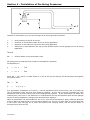
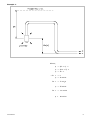
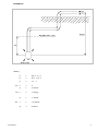
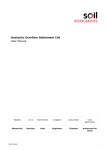
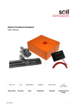
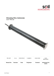
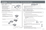
Hydraulic Piezometer System with High Pressure De-Airing Electric Pumps & Digital Readout User Manual Man028 2.0.2 04/07/2014 C.Spalton Andy Small Chris Rasmussen Manual No. Revision Date Originator Checked Authorised for Issue User Manual 1 Contents Section 1 : Introduction .................................................................................................. 3 Section 2 : Installation of Panel ...................................................................................... 4 2.01 Preparation and setting up ................................................................................ 4 Section 3 : Operation and Recharging ............................................................................. 6 Section 4 : Calculation of De-Airing Pressures ................................................................ 7 Section 5 : The De-Aired Water Boiler ........................................................................... 10 User Manual 2 Section 1 : Introduction WARNING: This de-airing unit is fitted with pressure regulators and pressure relief valves to safeguard the cylinders from over pressurisation when used in conjunction with the air compressor pump. When not in use, the regulator must always be left in the fully unscrewed (zero) position. When pressurising cylinder A, start the compressor and SLOWLY open the regulator to the required pressure; NEVER ALLOW THE PRESSURE TO BUILD UP SUDDENLY. After use, always unscrew the regulator to the zero position. On no account may the equipment be modified in any way. Ensure that all personnel receive adequate training before being allowed to operate the equipment without supervision. User Manual 3 Section 2 : Installation of Panel The frame should be mounted vertically and level on wooden battens on the wall of the terminal structure, at a convenient height for the operation of all the valves. The manifolds on the piezometer terminal panels should be connected to the busbar tee-piece connections on the deairing panel. Blank-off the other side of the tee-pieces with the stop-end fittings provided. Place the vacuum pump to the right of the panel, the pressure pump to the left-hand side. The pressure pump (Foot Type) connects to the Schrader fitting on valve K for standby use in the event of electric power failure. 2.01 Preparation and setting up It is essential to operate the valves in the order stated. Initially all the valves should be closed. 1. To completely evacuate the bladder and partly fill the pressure tank with clean water. Attach the vacuum pump with the hose supplied to valve F. Open valves G, N and F and apply vacuum until the bladder is completely evacuated. Close all valves. 2. Immerse one end of a rubber tube into a container of clean water and attach the other end to valve J at the base of the pressure tank A. Open valves J and F and operate the vacuum pump drawing the water into A. When this tank is seven-eighths full close valves J and F. Remove the hose from F, open valve F to release the vacuum, and then close. The de-airing unit is operated with two electric pumps and a boiler, which require an electric supply (see separate sheet). The electric compressor is connected to the pressure regulators via the tee-piece between the regulators with the nylon tube provided. The electric vacuum pump is connected to either valves F, G or H as required during operation. The water boiler is positioned on the floor below tank C. 3. Prepare some de-aired water in the de-airing boiler, allowing it to cool connect valve S on the boiler to valve M on tank C using a length of rubber hose. Attach the vacuum pump to valve H, open valves H and M and release the vacuum from the boiler by opening valve V (on the boiler). Open valve S and by operating the vacuum pump draw the de-aired water into tank C until it is three-quarters full. Close valves M and H. 4. Remove the vacuum hose and open valve H to release the vacuum. Open valves G and L, attach the vacuum hose to G and draw the de-aired water from C into tank B by operating the vacuum pump until tank C is only one-eighth full. Close all valves. To fill B completely it is necessary to repeat the operation but only half-filling C with de-aired water. When tank is almost full close all valves. Remove the vacuum hose from G. 5. Open valves E and N, switch on the compressor and slowly screw in the lower regulator to bring the pressure in A to 5-10mH20. Gently open valve G thereby inflating the bladder, displacing the de-aired water in B and forcing out any remaining air. (If the air were to be removed by applying a vacuum at G there is a risk of damaging the pump by drawing water into it). Any bubbles of air that cling to the rubber bladder and walls of the tank B should be dislodged by slapping the sides of the tank until they rise and accumulate under G. They may then be removed with pressure in A and momentarily opening valve G. It is important that User Manual 4 cylinder B is completely filled with de-aired water and all air excluded. Release pressure from A by switching off compressor, unscrew regulator G and opening valve F. Close all valves. 6. Attach the vacuum hose to F, open valves F, N, L and H and by evacuating A,water is drawn from inside the bladder to A, thus drawing de-aired water from C into B. When the bladder is fully deflated the tank A will again be seven-eighths full of water. Close valves F, N, L and H. Remove the vacuum hose from F and release the vacuum in A by opening F. Close all valves. 7. Open valves H and M to drain the water from tank C. Close all valves. The panel is now fully charged with de-aired water and ready for operation. User Manual 5 Section 3 : Operation and Recharging Attach the vacuum hose to valve H. Operate the compressor and lower regulator until the desired pressure is reached in A, as indicated by the pressure gauge. Having calculated the optimum deairing pressures, if a vacuum is required on the return side open valves H and R and operate the vacuum pump until the desired vacuum is reached as indicated by the vacuum gauge. Vacuum may be controlled by slightly opening the bleed valve T. Pressurised de-aired water from the supply tank B may be introduced into the upper manifold by opening appropriate valve on the panel. During operation of the unit the bladder in tank B should not be allowed to distend to more than three-quarters of the volume of the tank. At this point it is necessary to recharge with de-aired water as follows: 1. Close valves P and V (on the panel) to isolate the manifolds from the de-airing unit. 2. Open valves F and H to release the pressure and vacuum from the tanks, as indicated by zero readings on the gauges. Close all valves. 3. Drain tank C by opening H and M. 4. Attach the vacuum hose to H and the de-aired water supply to M. Operate the vacuum pump and draw de-aired water into C until three-quarters full. Close valves M and H. 5. Continue as in Sections 1.3.6 and 1.3.7 ensuring that the water in C does not empty while being drawn into B (avoid drawing air into B). User Manual 6 Section 4 : Calculation of De-Airing Pressures Consider a piezometer tip in the soil during the de-airing process as follows: u = pore pressure in the fill at the tip. p = pressure on the pressure side of the de-airing apparatus. v = pressure on the vacuum side of the de-airing apparatus. h = difference in head between the tip and the pressure and vacuum gauges on the de-airing apparatus. f AB and f BC = friction losses in the piezometer tube. All pressures are measured with respect to atmospheric pressure. For Equilibrium:p = h+u - f v = h+u - f AB BD Since AB = BC, and if no water flows in or out of the tip the velocity will be the same throughout the system then:f AB = f p = 2 (h + u) -v BC In a piezometer installation h is known, v can be maintained at a known value, and u for each tip can be estimated using previous pore pressure reading. In this way p can be calculated for each piezometer and de-airing carried out at the appropriate pressure. If the piezometer lies below the readout point, the term h, the difference in head between the tip and pressure and vacuum gauges on the de-airing apparatus, changes sign and becomes negative. When a piezometer has accumulated a lot of air, care should be taken to apply sufficient pressure to drive water at least as far as the tip before applying a vacuum to other lead, as the friction loss in the return tube carrying air is much less than in one carrying water, and air will be drawn in through the tip from the fill. User Manual 7 Example 1. Where; p = 2(h + u) -v p = 2(10 + 5) -v p = 30 - v for v = o p = 30 mH20 for v = -5 mH20 p = 35 mH20 for v = -10 mH20 p = User Manual 40 mH20 8 Example 2. Where; p = 2(h + u) -v p = 2(-7 + 4) -v p = -6 - v for v = o p = -6 mH20 for v = -5 mH20 p = -1 mH20 v = -10 mH20 p = 4 mH20 for User Manual 9 Section 5 : The De-Aired Water Boiler Up to 27 litres of the de-aired water can prepared in the boiler at one filling. An integral immersion coil heats the water to boiling thus expelling any air or gases in solution. By sealing the boiler and allowing it to cool, the steam and water vapour above the water condense thus creating a partial vacuum inside the boiler. This prevents further solution of air or gases. 1. Remove the central filler-cap using the special double handled spanner provided. Open valves V and S. 2. Pour in clean water to within 100mm of the top. 3. Connect the electrical cable to a suitable AC mains supply having checked the voltage of the unit and the supply, switch on at the mains. Bring to the boil and allow to boil for fifteen minutes. Switch off at the mains supply. 4. Close valves V and S and replace the central filler-cap. Allow to cool. WARNING: Although the cap is fitted with a pressure relief valve, never boil with the filler-cap on. NOTE: With a partial vacuum inside the boiler, never open valve S before opening valve V, as this will draw air into the de-aired water. SAFETY REQUIREMENTS: The 4 psi Pressure Relief Valve in centre of filler cap must be checked at intervals not exceeding 12 months by a competent person. POWER SUPPLY: The 110 volt unit requires 110V, 60Hz, 30 Amps per heater element. The 240 volt unit requires 240V, 50Hz, 15 Amps per heater element. The units must always be earthed. Bell Lane, Uckfield, East Sussex t: +44 (0) 1825 765044 e: [email protected] TN22 1QL United Kingdom f: +44 (0) 1825 744398 w: www.itmsoil.com Soil Instruments Ltd. Registered in England. Number: 07960087. Registered Office: 5th Floor, 24 Old Bond Street, London, W1S 4AW User Manual 10