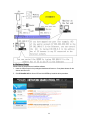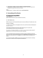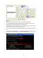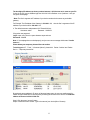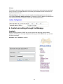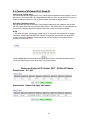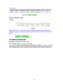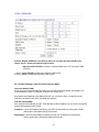
1
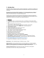
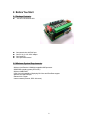
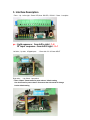
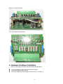
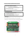
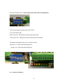
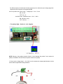
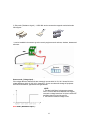
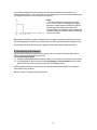
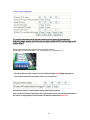
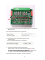
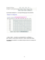
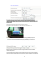
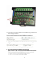
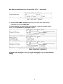
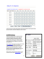
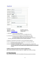
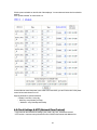
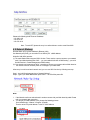
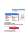
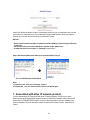
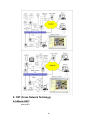
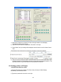
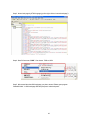
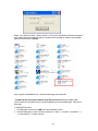
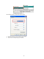
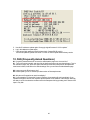
IP Power 9211
User Manual
1
USER MANUAL
IP POWER 9222
Version: V1.00
Oct. 21,2008
2
Warning: any changes to this equipment without permission may cause damages to your equipment!
This equipment has been proved to can be prevented from the influence of harmful electronic jamming
in normal business use condition.
IMPORTANT NOTICE
1. IP Power 9222 is deigned to be used in-door, we have no responsibility for the possible damage in
out-door use especially in the rain.。.
2. Please use the power adaptor provided by the dealer, we have no responsibility for the possible
damage in using other adaptors.
4. Do not use IP Power 9222 in strong shaking condition
5. Please contact the dealer If IP Power 9222 works improperly.
Copyright © 2006 All rights reserved. No part of this publication may be reproduced, stored in a
retrieval system, or transmitted in any form or by any means, electronic, mechanical, photocopying,
recording or otherwise, without the prior written consent of us.
3
Table of Contents
1.
Introduction.......................................................................................................................................... 5
1.1 Features:.......................................................................................................................................... 5
2. Before You Start .................................................................................................................................. 6
2.1 Package Contents:.............................................................................................................................. 6
2.2 Minimum System Requirements: ....................................................................................................... 6
3. Interface Description .......................................................................................................................... 7
4. Hardware & Software Installation ..................................................................................................... 8
4.1 Hardware Installation: (Plug RJ45 first before Power Jack!): ........................................................... 9
4.2 9211 Digital Input Hardware: .............................................................................................................. 9
4.3 Connecting to the Internet:................................................................................................................ 13
4.4 Software Setup:................................................................................................................................. 14
5. Connecting to the Device................................................................................................................. 15
5.1 Initial Setup using IPEDIT................................................................................................................. 15
6. Control and settings through the Webpage ................................................................................. 18
Logging In ................................................................................................................................................ 18
6.1 Control of IP Power 9211: Read IO.................................................................................................. 19
Name each Input of IP Sensor 9211 : Define I/O Name....................................................................... 19
6.3 System Configuration........................................................................................................................ 20
6.3.1 IP address Settings: Ethernet (LAN) and Internet (WAN)....................................................... 21
6.4 Change Password............................................................................................................................. 22
6.5 Advance Setup.................................................................................................................................. 22
6.6 DDNS Settings .................................................................................................................................. 29
6.7 Email Setup ....................................................................................................................................... 30
6.7 Time Scheduler ................................................................................................................................. 31
6.8 Clock Settings & NTP (Network Time Protocol).............................................................................. 32
6.9 Network Wakeup............................................................................................................................... 33
6.10 Firmware Update............................................................................................................................. 34
7. Associated with other IP network product.................................................................................... 35
8. CNT (Cross Network Technlogy).................................................................................................... 36
8.1 What is CNT? .................................................................................................................................... 36
8.2 IOTracker Software........................................................................................................................... 37
8.2.1 Setting up Master Control IOTracker ........................................................................................ 37
8.2.3 Setting up Slave in IOTracker.................................................................................................... 38
9. Customization & Integration............................................................................................................ 40
9.1 SNMP Setup...................................................................................................................................... 40
9.2 Http Commands ................................................................................................................................ 40
9.3 Webpage Customization .................................................................................................................. 42
10. FAQ (Frequently Asked Questions)................................................................................................. 46
4
1. Introduction
The IP Power 9222 is a Network Controller with 8 DO ( digital Output) . A specific PC or software is not
needed; you can easily control devices remotely and check the device status via the Internet anywhere
in the world.
Using a Browser such as Internet Explore Netscape, you can securely access the unit. It includes 8
Digital Relay Outputs and works like an controlled Server. You can integrate it with Home / Office
security, Personal entertainment, and Industrial field applications.
The API program is supported to help the integrator to easy program any software to integrate with
existing application systems in local computers. The IP POWER 9222 can be flexibly applied to Home
entertainment & industry security & systems with integrated management.
1.1 Features:
1. Embedded web server – no need to connect to a PC – Use Ethernet or Internet (LAN / WAN)
2. Accessible with popular web browsers- IE (Internet Explore) or Netscape – DO NOT need specific
S/W.
3. Comes with 8DO: Direct control relay output .
8 Set Controllers – Default 4 Set NO - Normal Open & 4 Sets NC - Normal Close
4. Network protocols supported: HTTP, DDNS, DHCP, Virtual and Dynamic IP.
5. Support RS232 to control .
6. Security code identification and Hardware reset function.
7. Individual LED indicates switch-working status.
8. Safe, durable, non-electric leakage and anti-farmable design.
9. Polar protection – will even connect contrary port.
10. Digital inputs provide de-bouncing function.
11. Update firmware by the TCP/IP network.
12. Embedded “ WATCH DOG “ for own 9222 anti-freeze.
13. Auto Controlled by our 9211 ( DI ) or the DI of our 9222Delux .
14. Timer Schedule -- pre-set the time schedule to turn power on / off thru Internet / Ethernet
15. Support NTP (Network Time Protocol) - synchronize the time of 9258 to the Internet web
16. Setup up own outlet default: set DO status as regain power.
17 Provide SDK (VB & VC) for own Software develop and application
18 Supply Exclusive IP Service for easily find on Internet by name.
Specification: 1. DC 5V (AC90-240 input) 2. D-SUB In & out port. 3. RJ45
Application field: can be associated with any kind of electrical equipments, no matter household
appliances or security equipment. It can manage the power supply through the web page; make it be
safer for the security equipment and more convenience for digital control at the far end.
Industrial application field: bank, financial security system, jewels, casino, cash register in
supermarket, park, traffic control, military equipment and airport.
5
2. Before You Start
2.1 Package Contents:
One set of IP SENSOR 9211
One network wire with RJ45 port
One 5V 1A, for 110~220V adaptor
One install CD
One rapid install manual
2.2 Minimum System Requirements:
* Minimum Intel Pentium II 300MHz/compatible AMD processor
* WINDOWS operating system (IE5.0+SP1)
* Minimum 64MB RAM
* VGA Card: with capability of displaying full-Colors and DirectDraw support
* Network card with RJ45 port
* Ethernet Hub / Router
* Internet network (Ethernet, xDSL with router)
6
3. Interface Description
* Front - Up : Left to right – Power LED, 8 set DO LED , RS-232 * Down : 8 set jacks
ps : Light sequence : from left to right : 1~8
DI input sequence : from left to right : 8~1
Left side ; * Up side : 8 Digital Inputs
Right side ;
* Down side: 5V 1A Power INPUT
* Up -Switch : 8pcs switch
* Down - Button: Reset button for power reboot / default setting
One click Press for power reboot.. Press more than 10seconds for change
back to default setting
7
Back side; * RJ-45 for network
Top ; * 8pcs buttons for test purpose.
4. Hardware & Software Installation
Before you star using the IP Power 9222, please follow the steps below:
Check the package to make sure the contents are complete.
Prepare one Ethernet HUB, or Router
Check the voltage of the power supply to make sure it is AC 110-240 volt
8
4.1 Hardware Installation: (Plug RJ45 first before Power Jack!):
1. Connect the 9200 to HUB through RJ 45 netting cable.
2. Connect the 9200 ( IN-BLACK ) to 9201( BLACK port) &
9200 ( OUT- BLUE ) to 9202 Output ( BLUE) through D-SUB cable.
3. Connect the HUB to the Internet (May through ADSL/XDSL modem).
4. Connect the power adapter to the 9200.
Power on your computer and power adapter of IP POWER 9222.
4.2 9211 Digital Input Hardware:
1.
2.
3.
4.
5.
Connect the 9200 to HUB through RJ 45 netting cable.
Connect the 9200 ( IN-BLACK ) to 9201( BLACK port) & 9200 ( OUT- BLUE ) to 920
Output ( BLUE) through D-SUB cable.
Connect the HUB to the Internet (May through ADSL/XDSL modem).
Connect the power adapter to the 9200.
Power on your computer and power adapter of IP POWER 9222.
Dry & Wet Setting
In 9211, the DRY or WET contact of each input ( in 9211) can be switched.
To setup the Dry or Wet contact of each input signal , please adjust the two Switches.
9
There are two switches in 9211. Please arrange all the setup to ON in the Right Switch.
Then user can setup the Dry/Wet contact in LEFT switch :
As no contact with the Input ,
Switch set as ON : LED light ON & means the input is Dry contact ,
Switch set as OFF : LED light is OFF which means the input is Wet contact
For example: the left switch setup input 1~4 is OFF & 5-8 is ON.
So the input 1- 4 is DRY contact and LED light OFF
the input 5- 8 is WET contact and LED light ON
4-2 . Connection Illustration:
10
For different request of normal state of electric equipment, 9211 offers four sets of voltage signal IN1IN4 and four sets of shortcut circuit signals IN5-IN8.
9211 Pro provide 4set Source mode - Voltage Input – Out 1 ~ Out 4
ON : 4V~24V
OFF : 0V ~ 3V
4 set Sink mode - Resistance input – Out 5 ~ Out 8.
ON : 200 ohm~ 0 ohm
OFF : 500 ohm ~ ∞
1. The polarity: Right - Positive & Left – Negative .
NOTE: Because of the polarity protective function, it won’t damage the product if user reverse the
polarity in installation. But it will cause the product cannot work properly
2. Source mode ( Voltage signal ) -- IN1 & IN4: can be connected to voltage signal detectors such as
smoke detector, light detector and gas detector.
11
3. Sink mode ( Resistance signal ) —IN5 & IN8: can be connected to magnetic reed switch as the
follow figures
It can be installed in the entrance guard or security equipment such as doors, windows, drawers and
safe case..
Source mode ( Voltage input) :
If the voltage difference between the two contacts in one set within 0V~3V, 9211 shows ON. It the
voltage difference within 4V~24V, 9211 shows OFF. So user can detect the change of equipment.
Such as smoke detector, light detector and gas detector.
NOTE:
1. The data in this figure is the average measure
value. To ensure the correct detection, we suggest
user set the voltage lower than 3V when it shows OFF
and higher than 4V when it shows ON
2. The maximum measure voltage is 24V.
.
Sink mode (Resistance Input ) :
12
If the resistance between the two contacts in one set within 0Ω~200Ω, 9211 shows ON. If the
resistance within 500Ω~∞, 9211 shows OFF. So user can detect the movement of equipment through
the magnetic reed switch or other kind of reactive sensors.
NOTE:
1. The data in this figure is the average measure
value. To ensure the correct detection, we suggest
user set the voltage lower than 200Ω when it shows
ON and higher than 500Ω when it shows OFF.
2. When measure the resistance of web contacts, the
maximum voltage is 5V and the maximum currency is
no more than 10Am.
PS: magnetic reed switch: using the magnetic field of the magnet to produce a signal when there is a
movement happened in switch. Low cost and easy to use is the chief characteristic of magnetic reed
switch. Most of them are used in security equipment, living product and automatic mechanism.
4.3 Connecting to the Internet:
After the Ethernet and router have been set correctly, you can access the IP Power 9222 from the
Internet. It will provide all kinds of convenience.
To correctly setup the device:
1.) Assign the right IP addresses and make sure that you can connect to your 9222 via local network.
2.) If a router/firewall is used, the router must be port mapped or port forwarded to the port of the
9222. Please refer to your routers manual in the port forwarding section.
After these steps have been correctly setup, you should be able to access the device through the
internet without any problems.
Below is a picture of what the setting may look like.
13
4.4 Software Setup:
Please follow the steps below to install the software.
1. Insert the CD that came in the package and windows will auto-run. If not please browse for the
Autorun.html file in CD.
.
2. Click IP KamVid 1070 in driver of CD and click OPEN top install the driver procedure.
14
3. Please follow the installation wizard and install all the recommended programs.
4. After installation is complete, a shortcut of “IPEDIT” & “INFINITY Cam” will be created on the
Desktop and in program list of start of your computer
NOTE:
* For NEW function – TO Record in “WMV” format, install IP KamVid 1070.
5. Connecting to the Device
5.1 Initial Setup using IPEDIT
1.) Click “ipEdit.exe”.
(Please check the 9222A-SL for power and Ethernet connection.)
A. LOCAL Devices area:
IPEDIT will search for all IP Products 9XXX series in the same local Ethernet. The default name of the
9222Delux is “IP Power”
1. Double click the IP address, it will highlight the device name, and IP information will be displayed to
the right of the screen.
The IP address of 9222Delux should be in the same subnet with your PC, subnet mask,
and default gateway must be the same as 9222Delux also.
For example, the IP address of 9222Delux is 192.168.10.9, so your computer needs to add an IP
address looks like 192.168.10.XXX to get connection to 9222Delux.
2. User can change the device name (please use numbers or letter) or IP (please set in the same
subnet as your PC) in the text window to the right. Then click Submit after setting finish. After about 20
seconds, the new setting will work. Click Update, the new setting of equipment will display in text
window.
3. You can also click “REF” in IPEDIT to check your PC to get the subnet information. And directly
press “APPLY to“ update the new IP settings of selected 9222A-SL
15
NOTICE:
1. Make sure the power and Ethernet connection of the 9222 are connect properly.
2. It can automatically obtain the virtual IP address after you run the ipeditv3.exe but only if your
Ethernet supports DHCP. Click the IP address to enter the web page.
If your Ethernet does not support DHCP, IP92XX you will change its IP address to fixed IP address.
Please follow the steps below to change the subnet of your PC:
3. If can not get in the 92XX web page, please set the segment of IP 9222Delux to be same as your
PC.
* You can get your PC network information – IP Addres, Subnet Mask and Default Gateway by step:
start execute key “cmd” in dialog
key “ipconfig” in MS-DOS mode
16
The last digit of IP address can be any number between 1~254, but can not be same as your PC.
If using in any PC, just use HUB and type the 192.168.0.100 in Browser or use “ipedit.exe “ then you
can get in the webpage.
* Note: The first 3 segments of IP address of your device needs to be the same as your default
gateway.
For Example: The IP address of the Gateway is 192.168.1.100, then the first 3 segments of the IP
address of your device will be 192.168.1.123.
4. The default username and password of IP Power 9222 are:
Username: admin
Password: 12345678
If forget the new password:
Login: super user (There is a space between super and user
Password: 1234568
Note : If the webpage does not load properly, and you see a error message which states“ Cookie
time out “
Please delete your temporary internet files and cookies.
To do this go to IE: “ Tools “ “Internet Options”, please click “Delete Cookies“ and “Delete
files“ in “Temporary Internet file“.
B.
Internet online devices:
By setting the server address in IP server of advanced setup page, the user can easily search for
his/her IP Power 9222Delux on internet just by searching for the name of the device. The default IP
address of IP server is 220.135.169.136.
Step1: Click the green “connect” button
Step2: In the device name section: Type in the name of your device (Min of 3 letters)
17
IP Server
IP Server gives the user the ability to easily search for the name of the device other than searching for
a long IP number. This flexibility allows the user to easily just remember the name of their device so
they can access it with ease.
To Enable IP Server: Go to Setup on the Left hand side of the Webpage and then make sure you
have enabled Transmit IP Address to IP Server. The default IP server IP Address is provided but the
user can also setup his/her own IPServer system and use that address as well
6. Control and settings through the Webpage
Logging In
Double click the IP address in IPEDIT and you can enter the login web page. Input the default
password 12345678 (you can change the password after log in), click the OK and then you can enter
the Web Control page.
Username: admin / Password: 12345678
18
6.1 Control of IP Power 9211: Read IO
Source mode (Voltage input):
IN1-IN4 contacts are active signal sensor. If the voltage difference between the two contacts in one set
within 0V~3V, 9212 shows ON. It the voltage difference within 4V~24V, 9212 shows OFF. So user can
detect the change of equipment. Such as smoke detector, light detector and gas detector.
Sink mode (Resistance Input):
IN5-IN8 contacts are short circuit sensor. If the resistance between the two contacts in one set within
0Ω~200Ω, 9212 shows ON. If the resistance within 500Ω~∞, 9212 shows OFF. So user can detect the
movement of equipment through the magnetic reed switch or other kind of reactive sensors.
NOTE:
1. The data in this figure is the average measure value. To ensure the correct detection, we suggest
user set the voltage lower than 200Ω when it shows ON and higher than 500Ω when it shows OFF.
2. When measure the resistance of web contacts, the maximum voltage is 5V and the maximum
currency is no more than 10Am.
Click the refresh button and user will see the similar figure like this. It represents the state of the four
sets of input signals (there may be some delay, it up to user network).
Name each Input of IP Sensor 9211 : Define I/O Name
Default Name : IN 1~IN8
Amend Name : Please click Apply after amend
19
Show in “Read I/O” page
Memory Function : User can save user name list in memory and call back the
setting as user get the default name after update firmware or after press H/W reset
button .
6.3 System Configuration
Setting the IP address for IP Power 9222:
Click the “Setup“ button on the left side under system.
Fill in the proper IP address, Subnet Mask, Default Gateway, and DNS. If you choose to use DHCP,
please make sure that your network supports DHCP service so the IP Power 9222 will automatically
find an IP address when it starts. You can also control the Beeper sound in system configuration..
20
IP Server: Register 9222Delux in our IP Server then user can easily get online IP address by
“Name “search. Please refer page16 for this function.
Http Command Verification: Setup the control possibility from HTTP command or SDK
(VB & VC)
1. Select “Cookie +Base64“: Enable Http command & SDK control
2. Select “Cookie“: Disable Http command & SDK control
6.3.1 IP address Settings: Ethernet (LAN) and Internet (WAN)
Local Area Network (LAN):
In LAN, you can set a fixed IP address or gain it from a DHCP server automatically. We suggest to use
a fixed IP address in order to let the other computers can visit the 9222.
Now type the new IP address in the address field of IE, you can visit the 9222. You also can use the
ipedit.exe to find the IP Power 9222 and modify its IP address.
From the Internet (WAN):
User can set the IP provided by your ISP. If the 9222 has a public IP address, you can control it through the
Internet. 9222 supports fixed IP, DHCP.
IP Address: Type in the IP address provided by your ISP. If IP Power 9222e is working with a Router,
please refer to the network settings of the Router.
Subnet Mask: Type in the Subnet Mask provided by your ISP. If IP Power 9222 is working with a
Router, please refer to the network settings of the Router.
21
Default gateway: Type in the Default Gateway provided by your ISP. If IP Power 9222 is working with
a Router, please refer to the network settings of the Router.
DNS Server: Fill in the IP address of DNS server. If you are in Taiwan, you can set it to 168.95.1.1.
DHCP Clients:
Enable – Activate DHCP service. DHCP will assign IP address for each PC.
Disable – Shut down the DHCP service. You can set the IP address by yourself.
Beeper: Enable – activate the beeper. Disable – turn off the beeper.
If you control the IP Power 9222 through the web page, the beeper will beep once
when the operation work.
Note:
1) IP address format is: xxx.xxx.xxx.xxx: yyyyy.
yyyyy represents the port number which ranges from 1 to 32767.
2) Subnet Mask: from 0 to 254 (xxx.xxx.xxx.0 ~ xxx.xxx.xxx.254)
3) If DHCP is disabled, user must set the TCP Port and default Gateway .If DHCP is
enabled, then the TCP port will be preset to 80( xxx.xxx.xxx.xxx: 80) and the
The DHCP server will set default gateway, too.
4) If the TCP port you set is not 80, your should type in the whole IP address and port in IE or
Netscape, such as http://xxx.xxx.xxx.xxx:yyyyy, or you can use the ipedit.exe to login into the
virtual IP of IP Power 9222.
6.4 Change Password
Click the change password option at the left window and you can enter the change password page.
Follow the instructions, fill in the old password and new password, then click the apply button to
confirm.
6.5 Advance Setup
22
To use the internal control function which we are going to introduce in
following page, please set all the pin on right switch to OFF and the light on DI
will be all off.
Please check the light status on DI board for the function it support:
We call “light turn ON” in DI board as “ LO”, and “light turn off “ in DI board as “ LF “.
1. As LO in either one each channel, 9211 will ask the setting IP KAM (9060A) take pictures.
User can also use the P5 area bottom of 9211 to control the LO.
As enable the function, as the DI status change, 9060 will take pictures.
User can also take pictures Hardware control. Set the Input as User can just press the bottom (=
P5) in 9211 to change status of any DI and the IP address of 9060 to do Snap Shot.
23
2 . As LO in either one each channel, 9211 will send TRAP message of 9211 to IP address in
Manager IP address.
User can use the P5 area bottom of 9211 to control the LO.
3. As LO in either one DI, 9211 will send E-mail to advice the certain
input status change.
User can use the P5 area bottom of 9211 to control the LO.
4. User can Auto control the DO of 9211 by DI status change
One DI can control 1~ 8 DO. User can also control other Do in 9222 / 9212 Delux .
User can also use the P5 area bottom of 9211 to control the LO.
Dynamic: as LO for one time, the DO part (in 9222 /9212Delux) change one time.
Static: as LO for one time, the DO(in 9222 /9212Delux) keep change.
Note: As enable this function - DI control DO, “ SET I/O “ will be disable.
24
If press bottom” Setting IN 1-8 “ , user will get following page to setup DI and DO.
ˇ means “enable “ ,as input is on,the output will be on ,LED light on 。
Note: Channel 1- 4 is NC, Channel 5- 8 is No, DO “ Light on” means status change.
If no setting in the controlled IP or no enable the output area, there is no message in for
“Controlled IP”
25
To use the internal control function which we are going to introduce in
following page, please set all the pin on left switch to OFF and the light on DI
will be all off.
Please check the light status on DI board for the function it supports:
We call “light turn ON” in DI board as “LO”, and “light turn off “ in DI board as “ LF “.
2. As LO in either one each channel, 9222 will ask the setting IP (9060A) take pictures.
You can also use the P5 area bottom of 9201 Input (of 9222Delux) to control the LO.
When the function is enabled, as the DI status changes, 9222A will access the 9060 IP
camera to take pictures.
You can also take pictures Hardware control. Set the Input as User can just press the bottom
(=P5) in 9201 Input to change status of any DI and the IP address of 9222A-SL to do SNAP shot.
26
3. As LO in either one each channel, 9222Delux will send TRAP message of 9222Delux to IP
address in Manager IP address.
You can use the P5 area bottom of 9201 Input (of 9222Delux) to control the LO.
5. As LO in either one DI, 9222Delux will send E-mail to inform the user of any input status
changes.
You can use the P5 area bottom of 9201 Input (of 9222Delux) to control the LO.
6. User can Auto control the DO of 9222Delux by DI status change
One DI can control 1~ 8 DO. You can also control other 9222Delux devices and units.
The P5 area bottom of 9201 Input (of 9222Delux) can be used to control the LO.
Dynamic: as LO for one time, the DO part changes one time.
Static: as LO for one time, the DO keeps changing.
27
Note: When you enable this function - DI controls DO, “ SET I/O “ will be disable.
7. Control function by MAC address: The device (Output of 9222, 9222, or 9060 Series) is
controlled by the Input of the 9222 or 9211.
This feature allows the user to search for the device within LAN or WAN with just a MAC address
without the need to port forward or port trigger the device.
If press the button ”Setting IN 1-8“ then you will get following page so you can setup DI and DO
settings.
28
In this screen you can select which Inputs activate which Outputs. From the picture above,
when the DI (IN7) is detected the DO(Out7) will be activated.
6.6 DDNS Settings
DDNS Server Settings: when your network connects
to the Internet through ADSL, your ISP will give you
a dynamic IP address. This might pose a problem
for people who might want to access your 9216 in
the local network because the IP is always changing
This DDNS feature was added to solve this problem.
Let’s explain that using the DDNS service provided by
www.dyndns.com:
First, we apply a domain name (for example, ippower 9222)
in www.dyndns.com for 9222, set the domain
password and select propel DNS server (for example,
dnsdojo.net) for domain name resolve. Then input
the Domain Name Server (host name), username,
password, and etc in the DDNS web page of the 9222.
Every time after that the 9222 will start or the user
May select select to submit,
9222 will send a message package including its current
IP address, domain name to www.dyndns.com, then
29
the DNS server you choose will link the domain name of
9222 to its current IP address. So, the visitor can visit
See the 9222 webpage by input the domain name of 9222
(aviosys.dnsdojo.net) In the address column in browser.
Note: When finish setting up the DDNS
click SAVE to make sure changes are kept.
Then press the UPDATE NOW button to
send DDNS message package to DDNS Server
immediately.
1. DDNS IP: Please fill in the IP address of DDNS Server and port number.
2. Domain: Please fill in your total domain name in Your Domain column.
3. DDNS user: Please fill in the DDNS domain name you applied here.
4. DDNS password: Fill in the DDNS password, which you applying domain process in DDNS
Server.
5. Enable DDNS : You can select true to enable DDNS function or select false to disenable it.
6. Proxy server setting: Sometimes the message package can not send to DDNS directly, you can
transmit
DDNS message package through proxy server. You can use the proxy server
by selecting TRUE in Proxy enable column. You can find the usable IP
address and port of proxy server in some BBS, or you can use some proxy
server searching software to search for usable IP address and port of proxy
server.
7. PROXY IP: Please fill in the IP address of proxy server here.
8. PROXY PORT: Please fill in the proxy port here.
6.7 Email Setup
IP Power can setup the e-mail address so that the user can receive status changes from the sensors.
When setting up the receiver e-mail address, IP Power will send its IP Address to the receiver.
30
For example:
* Mail Server: 123.com
* Password: XXXXXXXX
* Receiver 1: [email protected]
* Pop3Servcer: abc.com
* Sender: [email protected]
* Subject: 9222
1.) Mail Server: The server that sends e-mails out.
Please make sure that the server is an available mail server.
2.) Pop3 Server: The server receive IP address (in Internet WAN) from your ISP
for sending Internet IP address by E-mail when 9222 in Internet.
To receive IP address in WAN , please fill your ISP e-mail receive server.
In this part, please also set the DNS of your ISP in system configuration.
3.) Password: The password of this mailbox is no longer than 8 English characters.
4.) Sender: Please fill in the name of sender. The Mail Server must support SMTP and
these fields must be entered correctly.
5.) Receiver: No longer than 50 English letters. Please use blank space to separate each
receiver’s e-mail address. After you have finished setting up this portion you will receive
an email to inform you of the IP address of the IP Power 9222 every time you enter the
webpage.
6) Subject : The subject of the mail to be no more than 50 English letters.
7) Mail Body: Please type the content of the mail here, it cannot be left empty.
After you have finished all of the above settings, click “ SAVE “ button to save your settings.
6.7 Time Scheduler
User can control the time ON or OFF of the 9222Delux DO through a preset time scheduler.
31
Click the power schedule on the left side of the webpage. You can select and enter the time schedule
settings.
Click “power schedule” to control outlet 1-4.
If user wishes to control the power in one outlet of IP Power 9222, you can fill in the time in the power
control column and choose on or off.
Support parameter to operate scheduler:
* Disable / Just Once / every day
* Work Day: every Monday to Friday.
* Weekend: every Saturday and Sunday
6.8 Clock Settings & NTP (Network Time Protocol)
* User can enter the internal clock settings: year, month, day, hour, minutes and second.
* NTP function: customer can synchronize the time of 9222 to the Internet web address time.
32
Please refer following the NTP server IP address:
* 131.246.9.116
* 139.18.25.34
* 128.176.191.9
Note: To work NTP, please do set up in e-mail and have to receive e-mail from 9222.
6.9 Network Wakeup
Remote Wake up PC by MAC address in Ethernet (LAN)
Use Network port (RJ45), you can wake PC on WAN by PC `s MAC address.
Wake On LAN (WOL) premise:
(1) The main board needs to support “WOL“ function. There must be a port to connect to your network
card. If your Main board supports WOL ,you can enable this function in BIOS setting,you could
find this function in Power Management of BIOS setting.
(2) Your network card must support “WOL”, remember to connect your connect cable to Main board or
the network card can not send “power on” message to your main board.
After setup in main board and network card, you can use WOL function by following two-step:
Step 1: Log in 9222 web page and go to “Network Wakeup”
Step 2: Type in your MAC address then press “send ” – the PC will be power ON.
Note:
1. If the Network card is not onboard card, it needs to connect with your Main board by cable. Please
refer your network card connection
2. You can get your MAC address in PC, please refer following pictures:
Go to Network sign Status Support Details
Then the value in Physical Address “ is the PC` MAC address.
33
6.10 Firmware Update
If no firmware to update please do not go to this page.
As received new firmware, user can gain more functions for IP Power 9222 through firmware update.
Click the firmware update on the right side of the page; the following window will pop up.
Step1 : Click “firmware update“,you will see follow webpage :
Note: Do not click “ update “ if no firmware file update.
Step2: Click update button, the following window will pop up.
34
Step3: Click the Brower button to find the corresponding update file (you can download it from our web
site or ask it from the dealer), then click Update button to start update firmware. When the update is
finished, you must wait one minute before you restart the IP Power.
NOTICE:
* Due to network transfer unstable, to update the firmware (BIN) file, please arrange in EthernetLocal LAN.
* Please check with your reseller /distributor / importer for the update news.
* If update fail please refer chapter 11 “ Webpage Customization “
Step 4 after finish update please waits some second and then re-log in
PS: If use DHCP please enable DHCP
Note: :
1) If the Port is 80 then you can directly update。
2) If update fail ,you can manual reset the device and update again .
7. Associated with other IP network product
You can associate the IP Power 9222 with other IP network product of OUR in your home
Ethernet, such as IP Kamera 9000 network camera, IP Video 9100 network video server and IP
Sensor 9201, IP POWER 9222 Output E to monitor the equipments or sensors installed in the
doors or windows. This is an economic solution to achieve the network monitor, detection and
control.
35
8. CNT (Cross Network Technlogy)
8.1 What is CNT?
What is CNT?
36
CNT or Cross Network Technology was developed to create a hassle free and networking
safe system which allows IP Products to be setup with minimal network knowledge and
minimal setup time. With CNT anyone can setup the device without the technical
knowledge like TCIP, Port Forwarding, Static and Dynamic IP, and other confusing
networking terms. CNT ultimately save users time, manpower, frustration and
unnecessary costs. It makes everyone’s life easier.
8.2 IOTracker Software
Note: IP Server must be enabled on your device’s webpage. By default IP Server is
enabled.
8.2.1 Setting up Master Control IOTracker
* Only 9211 and Input box of 9222
37
1.) Execute I/O Tracker.exe: In Search Tool Area, device(s) located in LAN will display
automatically. Select the 9211 device
2.) Type in the device username & password in the section on the right.
3.) Press “Master” and your settings will be displayed at the left bottom corner for Master Control
Area.
*These Master Control settings will correspond to the setting in the devices webpage.
4.) After the connection has been made, to test the device the user can control Input status button
in Master Control Area. This basically mirrors the manual test buttons located on the 9211. The
Input status button in Slave control area can not be pressed or controlled.
8.2.3 Setting up Slave in IOTracker
* Only 9222 and Output box of 9222
1.) Execute I/O Tracker.exe: In Search Tool Area, the any device(s) in LAN will display
automatically. Select the 9222 device
2.) Type device password in the section on the right.
38
3.) Press “Slave” and a message at the right corner for Slave Control Area
39
9. Customization & Integration
9.1 SNMP Setup
9.2 Http Commands
Http Commands Syntax:
a.) http://IP Address/Set.cmd?CMD=Command
{Http Command syntax or format}
b.) http://username:password@IPAddress/Set.cmd?CMD=Command
{Adds username and password in command line} For IE6.0 and under version
c.) http://IP Address/Set.cmd?user=usename+pass=passwordCMD=command
40
{Add username and password in command line.} For all IE version, include 7.0 and above
Note:
IP Power 9202 Output Pro has predefined Relay Statuses.
Outputs 1 - 4: Normal Closed Relay (NC)
Outputs 5 - 8: Normal Open Relay (NO)
(The relay status of the outputs cannot be changed: Meaning that Output 1-4 will
always be Normally closed and Outputs 5-8 will always be Normally Open)
User
s
can
contr
ol
the
9222
’s
actio
n directly though the HTTP orders.
The syntax of the HTTP commands are listed below:
Command format: http://admin:password@ipaddress/Set.cmd?CMD=CmdType
*Http Function of 9211:
GetIO
Command format: http://admin:pasword@ ipaddress/Set.cmd?CMD=getio
http://admin:[email protected]/Set.cmd?CMD=getio
Output Message will return:
P51=0, P52=1, P53=0, P54=1, P55=0, P56=1, P57=0, P58=1
What this means is:
P5: Represents that this input message is from 9201 Input Module
(The P51 corresponds to the output port number. P51 = Input Module Port 1 P52 = Input Module Port 2
and so on).
The 0/1 after each Output: Represents whether there has been a status change or not.
0 = Keep Current Status
1 = Change Current Status
So for our current output message:
P51=0,P52=1P53=0,P54=1P55=0,P56=0,P57=0,P58=1HTTP/1.0 200 OK Connection: close
P52 = 1: Output 2: Status - On
P57 = 0: Output 7: Status - Off
P58 = 1: Output 8: Status - On
http://admin:[email protected]/Set.cmd?CMD=GetIo
Please refer to the chart provided for more information:
Input Number (Default)
Default Status
Input 1: Wet
Status = Off
Input 2: Wet
Status = Off
Input 3: Wet
Status = Off
Input 4: Wet
Status = Off
Input 5: Dry
Status = On
Input 6: Dry
Status = On
Input 7: Dry
Status = On
Status Change
Status = On
Status = On
Status = On
Status = On
Status = Off
Status = Off
Status = Off
41
Input 8: Dry
0 = Status Off & LED Off
Status = On
Status = Off
1 = Status On & LED On
9.3 Webpage Customization
Customer can use our Web page SDK to amend the word and background pictures for your
9222. If not familiar to write webpage, please do not do this amendment.
Important Notice:
1.
2.
3.
4.
Each file does not over the original file size.
The character word part does not over the original amount. For instance: “setup “ it is 5 characters.
Do not amend the structure of web page – can only amend words and background picture.
Only support HTML langrage to amend the web page.
Step 1: Open the 9222 Web page SDK file, and choose the web page planned to amend. For example:
web page “ipcontrol “ html file ”
Step 2: Open amend web page “I/O control “ html file:
42
Step 3. Amend web page by HTML langrage (get from right click as in amend web page”):
Step 4: Save file format as “UNIX”: Like choose “DOS to UNIX
Step 5. After amend the other 9222 web page you plan to amend. Please open program
“Make9222Html “ in 9222 web page SDK and just press” make html patch”.
43
Step 6. There will be a new file “ Update_2006-01-11.bin” which is the BIN file include the amend web
page. Please follow 9222-update procedure to update the firmware BIN file. Please note the Update
procedure must be done in port 80.
Note: program “Make9222Html.exe “ and amend web page must in same file.
* If update fail and can not get IP address by IP EDIT, please use RS232 jack (DB 9 Cable)
connect with the PC and 9222, and you can get IP address to log-in and update again. Please refer
follow step:
1.POWER OFF the 9222
1. Use DB9 cable connect to the COM1 of PC and the RS232 of 9222
2. Execute WIN program " Hyper Terminal”: please go to " Start" --> " program" " Accessories " -->
" Communications " “Hyper Terminal”.
44
Set the “Bits per second” as 19200 at COM1 (Must at COM1)
3. Then power ON 9222 you will get message in Hyper Terminal.
4. Please check the message and get your IP address.
45
5. Use this IP address to update again. We supply original firmware V1.22 for update f
6. Log in this address to update again.
7. If still cannot finish update successful, please check if create BIN file too big.
If need to ship BIN file, please use bin file V1.22.bin in SDK to update back to factory version.
10. FAQ (Frequently Asked Questions)
Q1: I forgot the password and can not enter the administration page now, what can I do?
A1: Turn on the power normally, and then click the ipedit.exe program to enter the web page. Type in
the username “super user” (there is a space between super and user) and press ok then press the
reset button in 9200; it will back to the default settings. Now you can enter the administration page.
Q2: I cannot open the IE web page, why?
A2: Please update your IE or use the up-to-date version of Netscape browser.
Q3: Why the on/off operation can work immediately?
A3: if you operate the IP Sensor 9201 Input in Ethernet, the operation will work immediately. If you
operate it through the Internet, the response speed depends on the situation of the network. Normally
the delay is not obvious because the date need to be transported during operating the IP Sensor 9201
Input is very little.
46