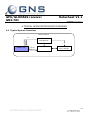
1
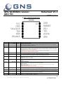
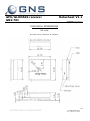
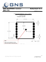
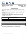
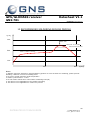
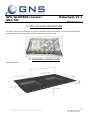
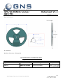
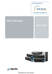
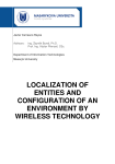
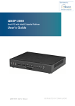
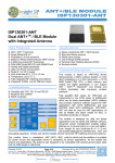
GPS/GLONASS receiver GNS 701 Datasheet V1.1 preliminary specification 1 INTRODUCTION GNS701 is a small autonomous GPS/GLONASS receiver, based upon the MediaTek MT3333 single chip, available with a finely tuned, high-sensitivity patch ceramic antenna. The receiver supports GPS and GLONASS simultaneously. The navigation performance and accuracy is further improved by using correction data from SBAS (WAAS, EGNOS, GAGAN, MSAS), QZSS or DGPS(RTCM). First Fixes after just a few seconds are achieved with the help of A-GPS using EPOTM ( Extended Prediction Orbit) and the EASYTM “self generated orbit prediction” algorithm. EASY TM (Embedded Assist System) does not require any resources or assist data from the host. The excellent low power design makes it easy to implement this receiver in power sensitive, battery supplied applications. The new AlwaysLocateTM power management feature will improve this behaviour additionally. It adaptively adjusts power consumption depending on the environment and motion conditions, in order to achive a balance between fix rate, power consumption and position accuracy. Very low power requirements (typ 66mW@ 3.3V, tracking for GPS+GLONASS) and internal voltage regulator makes it easy to run the receiver with various power supplies and allows direct connection to LiIon batteries. GNS701 offers the industry’s highest level of navigation sensitivity up to -165dBm1. It has superior dynamic performance at high velocity and provides effective protection against interference signals using MTAICTM ( Multi-tone active interference canceller). Up to 12 independent channel interference continious wave jammers <-80dBm can be eliminated or reduced. The embedded logger function LOCUS with a 16-hrs on chip memory makes this GPS module a complete track logger for many applications. With AlwaysLocateTM data logging can be achieved up to 32-hrs under standard conditions. In professional timing applications the outstanding high accuracy PPS (pulse per second) hardware pin is used for synchronization to GPS second. Typical accuracy is 10ns. 1 note: Based on chip specifications DISTRIBUTED BY TEXIM EUROPE © GNS-GmbH 2013 V 1.1, Apr 11th 2013 1 GPS/GLONASS receiver GNS 701 Datasheet V1.1 preliminary specification Features • • • • • • • • • • • • • • • • • • 1 GLONASS and GPS simultaneously 99 acquisition-/ 33 tracking channels Ultra high tracking/navigation sensitivity: -165dBm1 Smart antenna: finely tuned 18x18x4mm ceramic antenna SBAS (WAAS,EGNOS,MSAS,GAGAN, QZSS) correction support A-GPS by EPO “Extended Prediction Orbit” TM enables 7/14days prediction 12 Multitone Active Interference Canceller (MTAIC) for GPS-in-band jammer rejection EASY TM : Self generated orbit prediction support AlwaysLocate TM : Intelligent Algorithm for power saving High accuracy 1PPS output NMEA-0183 or binary protocol High update rate (up to 10/s) Embedded logger function with 16hrs internal memory GPS current consumption (@3.3V): Acquisition: 35mA Typical Tracking: 22mA Typical Low backup current consumption 15uA, typical SMD type with stamp holes Small form factor: 19.5x19.5x7.2mm CE, FCC and RohS certified note: Based on chip specifications DISTRIBUTED BY TEXIM EUROPE © GNS-GmbH 2013 V 1.1, Apr 11th 2013 2 GPS/GLONASS receiver GNS 701 Datasheet V1.1 preliminary specification 2 INDEX 1 INTRODUCTION ----------------------------------------------------------------------------------------- 1 2 INDEX --------------------------------------------------------------------------------------------------- 3 3 FUNCTIONAL DESCRIPTION ---------------------------------------------------------------------------- 4 3.1 3.2 3.3 3.4 3.5 3.6 3.7 3.8 3.9 3.10 3.11 3.12 3.13 3.14 3.15 3.16 3.17 3.18 3.19 3.20 System description -----------------------------------------------------------------------------------------------------------4 Block diagram-----------------------------------------------------------------------------------------------------------------4 GPS and GLONASS simultaneous operation --------------------------------------------------------------------------------5 Power Management Features ------------------------------------------------------------------------------------------------5 Logger function ---------------------------------------------------------------------------------------------------------------7 Active interference cancellation (MTAIC) -----------------------------------------------------------------------------------7 AGPS with EPO data ----------------------------------------------------------------------------------------------------------7 EASYTM self generated prediction data feature ------------------------------------------------------------------------------8 Pulse Per Second (PPS) ------------------------------------------------------------------------------------------------------9 SBAS (Satellite Based Augmentation) support --------------------------------------------------------------------------9 DGPS (Differential GPS) support -----------------------------------------------------------------------------------------9 Single sentence output ------------------------------------------------------------------------------------------------- 10 Last position retention -------------------------------------------------------------------------------------------------- 10 Geofencing function ----------------------------------------------------------------------------------------------------- 10 Magnetic variation feature ---------------------------------------------------------------------------------------------- 10 Distance calculation feature -------------------------------------------------------------------------------------------- 10 GPS/GLONASS almanac and ephemeris data ------------------------------------------------------------------------- 10 Real time clock (RTC) --------------------------------------------------------------------------------------------------- 10 UART interface----------------------------------------------------------------------------------------------------------- 11 Module default settings ------------------------------------------------------------------------------------------------- 11 4.1 Typical System Overview -------------------------------------------------------------------------------------------------- 12 5.1 GPS/GLONASS characteristics --------------------------------------------------------------------------------------------- 13 7.1 7.2 Absolute Maximum Ratings ------------------------------------------------------------------------------------------------ 14 Recommended Operating Conditions -------------------------------------------------------------------------------------- 14 4 TYPICAL APPLICATION BLOCK DIAGRAM ------------------------------------------------------------ 12 5 GPS/GLONASS characteristics ------------------------------------------------------------------------ 13 6 DESIGN GUIDELINES --------------------------------------------------------------------------------- 14 7 ELECTRICAL SPECIFICATION ------------------------------------------------------------------------- 14 8 PIN CONFIGURATION --------------------------------------------------------------------------------9 PHYSICAL DIMENSIONS -----------------------------------------------------------------------------10 RECOMMENDED PAD LAYOUT ----------------------------------------------------------------------11 NMEA DATA interface -------------------------------------------------------------------------------11.1 11.2 12 13 14 15 16 17 18 19 20 21 15 16 17 18 NMEA output sentences ------------------------------------------------------------------------------------------------- 18 NMEA command interface ---------------------------------------------------------------------------------------------- 19 MATERIAL INFORMATION --------------------------------------------------------------------------RECOMMENDED SOLDERING REFLOW PROFILE --------------------------------------------------TRAY PACKAGE INFORMATION --------------------------------------------------------------------TAPE&REEL INFORMATION -------------------------------------------------------------------------ORDERING INFORMATION -------------------------------------------------------------------------FCC COMPLIANCE-----------------------------------------------------------------------------------ENVIRONMENTAL INFORMATION ------------------------------------------------------------------MOISTURE SENSITIVITY ---------------------------------------------------------------------------DOCUMENT REVISION HISTORY -------------------------------------------------------------------RELATED DOCUMENTS ------------------------------------------------------------------------------ DISTRIBUTED BY TEXIM EUROPE © GNS-GmbH 2013 V 1.1, Apr 11th 2013 19 20 21 21 22 23 23 23 23 24 3 GPS/GLONASS receiver GNS 701 Datasheet V1.1 preliminary specification 3 FUNCTIONAL DESCRIPTION 3.1 System description The GNS701 is a high performance, low power GPS/GLONASS receiver that includes an integrated RF frontend (SAW Filter + LNA) and a finely tuned 18x18x4mm ceramic patch antenna. Due to high input sensitivity and integrated low noise amplifier (LNA), it can work at very weak GPS/GLONASS signals. GNS701 is a complete autonomous GPS/GLONASS receiver, including: - Full GPS/GLONASS processing, without any host processing requirements Standard NMEA message output A powerful NMEA command and control interface All clock sources integrated RF frontend integrates a low noise amplifier (LNA) and a SAW filter Rich additional features like geofencing, single sentence output, last position retention, magnetic variation, distance calculation Interface for UART, PPS output pin, Fix Status Indicator pin 3.2 Block diagram GPS patch antenna 11 NRESET 8 3D-Fix 7 1PPS SAW filter +Low Noise Amplifier 9 TX1 10 RX1 4 TX0 GPS /GLONASS chip VCC 1 Resistor 3V LDO 32.768kHz crystal ENABLE 6 VBACKUP 3 5 RX0 Resistor 16.368MHz TCXO GND DISTRIBUTED BY TEXIM EUROPE 2,12 © GNS-GmbH 2013 V 1.1, Apr 11th 2013 4 GPS/GLONASS receiver GNS 701 Datasheet V1.1 preliminary specification 3.3 GPS and GLONASS simultaneous operation GNS701 supports tracking of the GPS and the GLONASS satellite system at one time. This feature enhances the overall performance significant. Increased availability of number of satellites Increased spatial distribution allows better geometrical conditions Reduced Horizontal (HDOP) and Vertical Dilution of Precision (VDOP) factors In GPS-only operation, a minimum of 3 SVs is needed to determine a 2D position fix solution. When using both systems, 5 SVs are needed to determine the four unknowns and one more SV to calculate the GPS/GLONASS time offset. Using a combined receiver, users have an access to potentially 48 or more satellites. This high number of satellites can overcome the typical problems of restricted visibility of the sky, such as in urban canyons or indoor scenarios. 3.4 Power Management Features Power management schemes implemented for any GPS system requires an optimally tuned performance for both accuracy of the position fixes and the average power consumed for best user experience. GNS701 architecture achieves these both aspects by providing flexibility and design choices for the system integration, based on wide range of use cases and by leveraging on the proven silicon methodologies. Also GNS701 provides position, velocity and time measurements without any host loading. This, coupled with the optional built-in power management options, reduces the overall system power budget. Selectable Power management features: In Standby mode RF frontend and internal MPU are switched to deep sleep state. Power consumption is reduced.This state can be entered by sending the NMEA command: $PMTK161,0*28<CR><LF>. Leaving standby mode and resuming to normal operation will be managed by sending any byte to the module. DISTRIBUTED BY TEXIM EUROPE © GNS-GmbH 2013 V 1.1, Apr 11th 2013 5 GPS/GLONASS receiver GNS 701 Datasheet V1.1 preliminary specification Backup mode can be entered by sending NMEA command: $PMTK225,4*2F<CR><LF>. The GPS core will shut down autonomously to backup state, Vcc supply can now be switched off by an external power supply switch. Periodic mode describes a power mode, which will autonomously power on/off the module in programmable time slots with reduced fix rate. Periodic mode is useful during stationary operation or if position fixes are just needed from time to time. Since power consumption in GPS off times is nearly zero, the power consumption in periodic mode can be estimated by Ptracking * (ton/(ton+toff)). Periodic mode is controlled with NMEA command $PTMK225. See document GPS/GLONASS_NMEAcommandInterface manual for programming details. AlwaysLocateTM feature provides an optimized overall GPS/GLONASS system power consumption in tracking mode under open sky conditions. Always Locate is an intelligent control of periodic mode. Depending on the environment and motion conditions, GNS701 can adjust the on/off time to achieve balance of positioning accuracy and power consumption. The best power saving will be made under good reception in stationary mode. Critical reception conditions and dynamic movements will need full activity of the GNSS engine which causes nominal power requirements (29mA typ in tracking mode). DISTRIBUTED BY TEXIM EUROPE © GNS-GmbH 2013 V 1.1, Apr 11th 2013 6 GPS/GLONASS receiver GNS 701 Datasheet V1.1 preliminary specification 3.5 Logger function GNS701 provides an autonomous logger function that automatically stores position information in an internal 128kB flash memory. A complete tracking unit can be realized without any external CPU or memory. The parameters for logging are programmable via the NMEA command interface. The following parameter can be set to optimize logging time: - logger rate The commands for logger include: - start logging - stop logging - erase memory - readout memory please refer to the GPS/GLONASS_NMEAcommandInterface manual for details. Logger data rate Logger data memory Logger trigger 1/15 Internal Logger Function 1 1/s 128 kBytes programm able Flash memory Logger can be triggered on various events 3.6 Active interference cancellation (MTAIC) Because different wireless technologies like Wi-Fi, GSM/GPRS, 3G/4G, Bluetooth are integrated into portable systems, the harmonic of RF signals may influence the GPS reception. The multi-tone active interference canceller can reject external RF interference which come from other active components on the main board, thus improving the performance of GPS reception. GNS701 can cancel up to 12 independent continuous wave (CW) channels having signal levels of up to -80dBm. The functionality is enabled by default and increases power consumption by about 1mA. 3.7 AGPS with EPO data AGPS (assisted GPS) allows to shorten TTFF (TimeToFirstFix) by injecting ephemeris data from an external source into the module’s memory. With the help of these data, the module does not need to acquire satellite positions by receiving the data from the satellites. Depending on time and position information, that is still available in the module memory, the TTFF can be reduced to just a few seconds. The GNS AGPS service is based on a short term predicted data service. The predicted data will be fully processed by the GPS engine. The host must load the data from the web and transfer them over the UART into the module: 1. Check GNS701 module EPO (Extended Prediction Orbit) data for validity by comparing the time. 2. Connect to web server through network connection (GPRS, WLAN, LAN,..). 3. Download file. There are just two files, covering all GPS satellites. The first file (MTK7d.EPO) is for 7 days (53kB), the other is 106Kbytes for 14 days (MTK14d.EPO) DISTRIBUTED BY TEXIM EUROPE © GNS-GmbH 2013 V 1.1, Apr 11th 2013 7 GPS/GLONASS receiver GNS 701 Datasheet V1.1 preliminary specification 4. “Parse” file, using software example. This is quite easy, there must be added some header bytes and a checksum and a control counter. GNS offers software support on this. 5. Download to GNS701 receiver. Please refer to the GPS/GLONASS_NMEAcommandInterface manual for details. If the host has low memory available, there’s no need to save the whole file. The steps 3..5 can be done frame by frame needing less than 2kBytes of buffer memory. Code samples and support for several platforms are available from GNS (in preparation). Thanks to the predicted system, download data stay valid for up to 14 days. Therefore, users can initiate the download everytime and benefit from using (W)LAN instead of using expensive GSM. File size will be ~50kBytes for a one week prediction data set. AGPS characteristics System File size for data download Maximum prediction time TTFF TTFF 7 53 14 1 15 kB days sec sec 6hrs predicted data 1 week prediction data Time and last position available Last position available 3.8 EASYTM self generated prediction data feature GNS701 includes an internal prediction system, that allows to sample satellite orbit data during operation and use that data to speed up TTFF on later starts.The prediction time frame is up to three days forward. Although this prediction feature does not provide the very short TTFF that is achieved using AGPS, it can help to find a fix solution faster and in weak signal condition scenario. Prediction data will be kept in memory as long as VBACKUP is present. This option is activated by default. Note: The EASY functionality is only supported, if “VBACKUP” pin is conntected and the NMEA update rate is 1Hz. DISTRIBUTED BY TEXIM EUROPE © GNS-GmbH 2013 V 1.1, Apr 11th 2013 8 GPS/GLONASS receiver GNS 701 Datasheet V1.1 preliminary specification 3.9 Pulse Per Second (PPS) GNS701 provides a Pulse Per Second (PPS) hardware output pin for timing purposes. After calculation of a 3D position fix (default setting), the PPS signal is accurately aligned to the GPS second boundaries. The pulse generated is approximately 100 milliseconds in duration and the repetition rate is 1 second. On request PPS output can activated on a 2D- fix or after power-up of the module, providing a time accuracy decreased PPS signal. T2 T1 T1 = 100ms T2 = 1sec GNS701 module provides an exceptionally low RMS jitter of typical 10 nanoseconds. 1PPS pulse duration 1PPS time jitter - 1PPS rise and fall time PPS characteristics based upon a 3D-fix 100 msec 10 nsec RMS 5 nsec Pulse rising edge deviation from expected pulse time, measured with full 3D fix 10%..90%, load is 10k||5pF 3.10 SBAS (Satellite Based Augmentation) support GNS701 supports Satellite Based Augmentation for improvement of the navigation precision. Correction data is sent from geostationary satellites to the GPS/GLONASS receiver. GNS701 supports European, US, and Asian augmentation systems (EGNOS, WAAS, GAGAN, MSAS, QZSS) to enable precision improvements in nearly every region of the world. SBAS is active by default and will automatically track the available SBAS satellites. It can be disabled by NMEA command. See document GPS/GLONASS_NMEAcommandInterface manual for details Note : In SBAS mode, the maximum NMEA sentence update rate is limited to 5 per second. 3.11 DGPS (Differential GPS) support GNS701 accepts DGPS input in RTCM format. DGPS provides precision position fixes down to centimetres and is used in professional applications like agriculture. The second UART (UART_1) of the module is used to feed the data in. DGPS is deactivated by default. For configuration of the UART port, some NMEA commands must be implemented. See GPS/GLONASS_NMEAcommandInterface document for details. DISTRIBUTED BY TEXIM EUROPE © GNS-GmbH 2013 V 1.1, Apr 11th 2013 9 GPS/GLONASS receiver GNS 701 Datasheet V1.1 preliminary specification Note : Since SBAS and DGPS both do (different) corrections on the fix position solution, they cannot be used at the same time! SBAS / DGPS usage is programmed through the NMEA Interface. 3.12 Single sentence output GNS701 allows to reduce data transfer to host to a minimum. Reduced data transfer can save host processor activity times and thus reduce system power consumption. All relevant information will be provided in a single sentence output. To save further channel load, the sentence can be formatted as binary. Need of firmware customization. 3.13 Last position retention Depending on the application, it might be useful to retain the last position or to clear the position when having no fix solution. Last position retention can be enabled or disabled. When enabled, the last known position is outputted in the NMEA sentences. Need of firmware customization. 3.14 Geofencing function GNS701 has an internal algorithm to determine whether the actual position is within a circular area around a predefined location point. A proprietary sentence indicates the “inside” or “outside” status. Need of firmware customization. 3.15 Magnetic variation feature As the magnetic variation feature is enabled, data output provides informations about the degree of magnetic variation and the measured magnetic heading. Need of firmware customization. 3.16 Distance calculation feature This feature allows to request the real “line of sight” distance in relation to a predefined position. This feature can remove some load from the host processor. Need of firmware customization. 3.17 GPS/GLONASS almanac and ephemeris data For quick re-acquisition of the GPS/GLONASS receiver after off-times, the GPS/GLONASS engine should have access to almanac and ephemeris data. This data is permanently stored inside GNS701 module, even if all power supplies have been removed. When the receiver is powered-up again, the data will be used to allow a quick re-acquisition, as soon as a coarse time information is available. Time will be available immediately, when RTC is kept running. 3.18 Real time clock (RTC) GNS701 has a real time clock with 32,768Hz crystal on board. As long as VBACKUP is connected to a power source, the real time clock and the module memory can be kept alive at very low power consumption of just 15uA. The RTC will track the current time and enable the module to start from sleep states with very fast time to first Fix (TTFF). DISTRIBUTED BY TEXIM EUROPE © GNS-GmbH 2013 V 1.1, Apr 11th 2013 10 GPS/GLONASS receiver GNS 701 Datasheet V1.1 preliminary specification 3.19 UART interface GNS701 core and I/O sections work at 3.3V nominal. Absolute Maximum Ratings should not be exceeded. Should the GNS701 be interfaced to a host with I/O at higher/lower levels, level shifters should be used. UART baud rate is 9600baud by default. The baud rate can be modified to higher rates by a NMEA software command. See document GPS/GLONASS_NMEAcommandInterface manual for details. UART Default Settings Parameter Value Baud rate Data length Stop bit Parity 9600 8 bits 1 None 3.20 Module default settings The GNS701 receiver comes with default settings, which are persistently programmed. Whenever power is removed from the module (both VCC and VBACKUP), the settings will be reset to the values shown in the following table. Default settings Setting Default value UART setting Fix frequency (update rate) NMEA sentences NMEA rate Self survey prediction mode: EASYTM Active interference cancellation:MTAIC DGPS option Datum Logging parameters Single sentence output Last position retention Magnetic variation Geofencing function Distance calculation 9600,8,N,1 1/sec Refer to chapter 11.1 “NMEA output sentences” Once a second: RMC,GSA,VTG,GGA every 5 sec :GSV sentences enabled enabled SBAS enabled WGS 84 Full&Stop / Content Basic / Interval 15 sec Customized firmware needed Customized firmware needed Customized firmware needed Customized firmware needed Customized firmware needed On request, other options can be selected as preprogrammed (persistent default) options. Please contact the GNS support for your project requirements. Note : Customized options are solely available for fixed order lots. DISTRIBUTED BY TEXIM EUROPE © GNS-GmbH 2013 V 1.1, Apr 11th 2013 11 GPS/GLONASS receiver GNS 701 Datasheet V1.1 preliminary specification 4 TYPICAL APPLICATION BLOCK DIAGRAM 4.1 Typical System Overview Mobile device Power Management VCC V Backup 3.3V GNS701 UART RX Host Processor UART TX DISTRIBUTED BY TEXIM EUROPE MMI (keys, display) © GNS-GmbH 2013 V 1.1, Apr 11th 2013 12 GPS/GLONASS receiver GNS 701 Datasheet V1.1 preliminary specification 5 GPS/GLONASS characteristics 5.1 GPS/GLONASS characteristics Parameter Min Typ Max Unit Note general Frequency Datum AGPS Output data frequency Navigation&tracking sensitivity1 Acquisition sensitivity1 Reacquisition sensitivity1 TTFF hotstart1 TTFF autonomous warm start1 TTFF autonomous cold start1 Reacquisition time1 Number of channels tracking Number of acquisition channels Dimension Weight 1575.42 1598.0625~ 1609.3125 7 1/10 14 10 1 -165 -148 -163 1 34 35 <1 33 99 19.5x19.5x7.2 8 Power consumption GPS ACTIVE (acquisition) GPS ACTIVE (tracking) Backup current @ 3V MHz GPS L1 MHz GLONASS L1 days 1/sec dBm dBm dBm sec sec sec sec mm g 35 mA 22 mA 15 uA WGS84 Configurable autonomous Cold start Hot start All SVs @-130dBm All SVs @-130dBm All SVs @-130dBm All SVs @-130dBm Tolerance is +/-0.2 mm NMEA frequency = 1/sec, 3.3V, SBAS enabled, MTAIC enabled NMEA frequency = 1/sec, 3.3V, SBAS enabled, MTAIC enabled Accuracy Position Position Velocity Velocity error (50%CEP) error (50%CEP) error error Operation altitude Operation velocity Operation acceleration 1 - 3 2.5 0.1 0.05 - - - ITAR limits 18,000 515 4 m m m/s m/s Without aid 2D-RMS Using (SBAS) 2D-RMS Without aid Using (SBAS) m m/s G note: based on chip specifications DISTRIBUTED BY TEXIM EUROPE © GNS-GmbH 2013 V 1.1, Apr 11th 2013 13 GPS/GLONASS receiver GNS 701 Datasheet V1.1 preliminary specification 6 DESIGN GUIDELINES Although GNS701 GPS/GLONASS receiver provides best performance at low power consumption. Special care should be taken to provide clean signal and clean power supplies. Power lines should be blocked near to the receiver with low ESR capacitors. Radiated noise from neighbour components may also reduce the performance of the receiver. Please refer to “GNS701 Starter Kit User Manual” for more informations, downloadable at the GNS forum: www.forum.gns-gmbh.com . 7 ELECTRICAL SPECIFICATION 7.1 Absolute Maximum Ratings Parameter Supply voltage range: Vcc Backup voltage: VBACKUP Value Unit 3.0 to 4.3 2 to 4.3 V V 7.2 Recommended Operating Conditions Parameter Min Typ Max Unit Vcc Vcc ripple voltage 3.0 3.3 4.3 V 50 VBACKUP 2.0 3.0 4.3 V RX0 TTL H Level RX0 TTL L Level TX0 TTL H Level TX0 TTL L Level 2.0 0 2.4 0 Vcc 0.8 2.8 0.4 V V V V Storage temperature -50 90 °C Operating temperature -40 85 °C DISTRIBUTED BY TEXIM EUROPE Note supply voltage mVpp Backup voltage for RTC and memory retention, must be available during normal operation Condition: VCC=3.0V~4.3V Condition: VCC=3.0V~4.3V Condition: VCC=3.0V~4.3V Condition: VCC=3.0V~4.3V © GNS-GmbH 2013 V 1.1, Apr 11th 2013 14 GPS/GLONASS receiver GNS 701 Datasheet V1.1 preliminary specification 8 PIN CONFIGURATION Top View Pin 1 Name VCC I/O P Description & Note Main DC power input The main DC power supply for the module. The voltage should be kept between from 3.2V to 5.0V. The ripple must be limited under 50mVpp (Typical: 3.3V). 2 3 GND VBACKUP P P Ground Backup power input for RTC & navigation data keep 4 TXO O Serial Data Output A for NMEA output (TTL) 5 RXO I Serial Data Input A for Firmware update (TTL) 6 ENABLE I High active, or keep floating for normal working 7 1PPS O 1PPS Time Mark Output 2.8V CMOS Level 8 3D_FIX O 3D-Fix Indicator This connects to the backup power of the GPS module. Power source (such as battery) connected to this pin will help the GPS chipset in keeping its internal RTC running when the main power source is turned off. The voltage should be kept between 2.0V~4.3V, Typical 3.0V. If VBACKUP power was not reserved, the GPS receiver will perform a lengthy cold start every time it is poweredon because previous satellite information is not retained and needs to be re-transmitted. This pin must be connected for normal operation. This is the UART-A transmitter of the module. It outputs GPS information for application. This is the UART-A receiver of the module. It is used to receive commands from system Enable (High): 1.8<=V enable <=VCC Disable (Low): 0V<=V enable <=0.25V This pin provides one pulse-per-second output from the module and synchronizes to GPS time. Keep floating if not used. The 3D_FIX is assigned as a fix flag output. If not used, keep floating. Before 2D Fix The pin will continuously toggle with 1Hz. output one second high-level and one-second low-level signal After 2D or 3D Fix The pin will continuously output low-level signal. This pin may not connected to high-level at power-on sequence. 9 TX1 O Serial Data Output A for NMEA output (TTL) 10 RX1 I Serial Data Input A for Firmware update (TTL) 11 NRESET I Reset Input, Low Active 12 GND P Ground This is the UART transmitter of the module. It outputs GPS information for application. If not used, keep floating. This is the UART receiver of the module. It is used to receive commands from system. If not used, keep floating. Low active, it causes the module to reset. If not used, keep floating. (1) I = INPUT; O = OUTPUT; I/O = BIDIRECTIONAL; P = POWER PIN; ANA = ANALOG PIN. DISTRIBUTED BY TEXIM EUROPE © GNS-GmbH 2013 V 1.1, Apr 11th 2013 15 GPS/GLONASS receiver GNS 701 Datasheet V1.1 preliminary specification 9 PHYSICAL DIMENSIONS TOP VIEW all units in mm, tolerance is ±0.2mm DISTRIBUTED BY TEXIM EUROPE © GNS-GmbH 2013 V 1.1, Apr 11th 2013 16 GPS/GLONASS receiver GNS 701 Datasheet V1.1 preliminary specification 10 RECOMMENDED PAD LAYOUT all units in mm Footprint Top View DISTRIBUTED BY TEXIM EUROPE © GNS-GmbH 2013 V 1.1, Apr 11th 2013 17 GPS/GLONASS receiver GNS 701 Datasheet V1.1 preliminary specification 11 NMEA DATA interface GNS701 provides NMEA (National Marine Electronics Association) 0183 compatible data. A set of proprietary NMEA commands are available to send control messages to the receiver. These commands are described in a separate document: GPS/GLONASS_NMEAcommandInterface manual. For standard operation, no commands are needed; the module will start outputting NMEA sentences after power supply has been attached. GNS701 will always start communication output with 9600 bit per second. If non standard options are needed (f.e. other baud rate , other NMEA sequence) they can be programmed from host controller during runtime. Important note : Options set by using NMEA command interface are not persistent! They will be lost when power is removed. A backup supply at VBACKUP will be sufficient to keep them. 11.1 NMEA output sentences NMEA output sentences Type content RMC GGA GLL GSA VTG GSV Recommended Minimum Navigation Information Fix Data, Time, Position and fix related data Geographic Position - Latitude/Longitude DOP and active satellites Course and Speed Information relative to the Ground Satellites in view NMEA output sentences indentifier, retlated to its GNSS system: NMEA output identifier System GPS GPS+GLONASS GGA GPGGA GPGGA GSA GPGSA GNGSA GSV GPGSV GPGSV GLGSV RMC GPRMC GPRMC1 or GNRMC VTG GPVTG GPVTG Note1: Before 3D fix RMC output is GPRMC, after 3D fix it changes to GNRMC. DISTRIBUTED BY TEXIM EUROPE © GNS-GmbH 2013 V 1.1, Apr 11th 2013 18 GPS/GLONASS receiver GNS 701 Datasheet V1.1 preliminary specification 11.2 NMEA command interface GNS701 NMEA command interface allows to control settings and the extended functions. The command interface specification is available in an extra document: GPS/GLONASS_NMEAcommandInterface manual. Two groups of commands are available: Setting commands do modify the behavior of the module. Note : Modified settings will be valid as long as the module is powered through VCC or VBACKUP. (f.e. : setting of a new baud rate). After removing VCC and VBACKUP, all settings are reset to their default values. Action commands will perform the specified action one time after the command has been received. (f.e. : request for cold start) Commands are always started with $PTMK, directly followed by the command number 000..999. Each command must be terminated by *<chksum>and a <CR><LF>. The checksum calculation is simple, just XOR all the bytes between the $ and the * (not including the delimiters themselves). Then use the hexadecimal ASCII format. 12 MATERIAL INFORMATION Complies to ROHS standard ROHS documentations are available on request Contact surface: gold over nickel DISTRIBUTED BY TEXIM EUROPE © GNS-GmbH 2013 V 1.1, Apr 11th 2013 19 GPS/GLONASS receiver GNS 701 Datasheet V1.1 preliminary specification 13 RECOMMENDED SOLDERING REFLOW PROFILE T[°C] 300 250°C max 250°C for 10 sec max 230°C for 40 sec max 200 160°C 190°C 120 sec reflow solder 100 100 200 t[sec] Notes: 1. GNS701 should be soldered in upright soldering position. In case of head-over soldering, please prevent shielding / GNS701 receiver from falling down. 2. Do never exceed maximum peak temperature 3. Reflow cycles allowed : 1 time 4. Do not solder with Pb-Sn or other solder containing lead (Pb) 5. This device is not applicable for flow solder processing 6. This device is not applicable for solder iron process DISTRIBUTED BY TEXIM EUROPE © GNS-GmbH 2013 V 1.1, Apr 11th 2013 20 GPS/GLONASS receiver GNS 701 Datasheet V1.1 preliminary specification 14 TRAY PACKAGE INFORMATION The GPS receivers are placed on a tray for quantities below 100 pieces. The trays will be stacked and packed together.The trays are placed inside an antistatic bag. 15 TAPE&REEL INFORMATION Tape information: DISTRIBUTED BY TEXIM EUROPE © GNS-GmbH 2013 V 1.1, Apr 11th 2013 21 GPS/GLONASS receiver GNS 701 Datasheet V1.1 preliminary specification Reel information: H= 44.5mm Number of devices: 250pcs/reel 16 ORDERING INFORMATION Ordering information Type Part# label marking Description GNS701 4037735104846 GNS701QYYWWSN GNS701receiver YYWW => date code SN => serial number DISTRIBUTED BY TEXIM EUROPE © GNS-GmbH 2013 V 1.1, Apr 11th 2013 22 GPS/GLONASS receiver GNS 701 Datasheet V1.1 preliminary specification 17 FCC COMPLIANCE This product has passed FCC 911 compliance successfully. The module emission and immunity has been proven to be compliant. However, applications using this module as a component must pass CE and/or FCC again in whole. 18 ENVIRONMENTAL INFORMATION This product is free of environmental hazardous substances and complies with 2002/95/EC. (RoHS directive). 19 MOISTURE SENSITIVITY This device must be prebaked before being put to reflow solder process. Disregarding may cause destructive effects like chip cracking, which leaves the device defective ! Shelf life 6 months , sealed Possible prebake recommendations 12 hrs @ 60°C Floor life (time from prebake to solder process) <72 hrs 20 DOCUMENT REVISION HISTORY V1.0 Jan 29 2013 M.Reiff V1.1 Apr 11 2013 M.Reiff initial document Tape&Reel information added; PPS direction at blockdiagram corrected; Related documents updated; Receiver default settings supplemented; DISTRIBUTED BY TEXIM EUROPE © GNS-GmbH 2013 V 1.1, Apr 11th 2013 23 GPS/GLONASS receiver GNS 701 Datasheet V1.1 preliminary specification 21 RELATED DOCUMENTS Title GPS/GLONASS NMEAcommandInterface manual GNS701 StarterKit user manual NMEA protocol GNS GMBH Description / file Available from Detailed description of NMEA commands www.forum.gns-gmbh.com User manual for the GNS701 receiver based evaluation kit Detailed description of NMEA protocol www.forum.gns-gmbh.com www.forum.gns-gmbh.com 2013 THE INFORMATION IN THIS DOCUMENTATION DOES NOT FORM ANY QUOTATION OR CONTRACT. TECHNICAL DATA ARE DUE TO BE CHANGED WITHOUT NOTICE. NO LIABILITY WILL BE ACCEPTED BY THE PUBLISHER FOR ANY CONSEQUENCE OF THIS DOCUMENT'S USE. REPRODUCTION IN WHOLE OR IN PART IS PROHIBITED WITHOUT THE PRIOR WRITTEN CONSENT OF THE COPYRIGHT OWNER DISTRIBUTED BY TEXIM EUROPE © GNS-GmbH 2013 V 1.1, Apr 11th 2013 24 Partner in Electronic Components & Supply Chain Solutions The Netherlands Denmark Elektrostraat 17 NL-7483 PG Haaksbergen Tel: +31 (0)53 573 33 33 Fax: +31 (0)53 573 33 30 [email protected] Nørregade 15 DK-9240 Nibe Tel: +45 88 20 26 30 Fax: +45 88 20 26 39 [email protected] Belgium United Kingdom Gentsesteenweg 1154-C22 Chaussée de Gand 1154-C22 B-1082 Brussel / Bruxelles Tel: +32 (0)2 462 01 00 Fax: +32 (0)2 462 01 99 [email protected] St. Mary’s House, Church Lane Carlton Le Moorland Lincoln LN5 9HS Tel: +44 (0)1522 789 555 Fax: +44 (0)845 299 22 26 [email protected] Germany Germany Justus-von-Liebig-Ring 7-9 D-25451 Quickborn Tel: +49 (0)4106 627 07-0 Fax: +49 (0)4106 627 07-20 [email protected] Martin-Kollar-Strasse 9 D-81829 München Tel: +49 (0)89 436 086-0 Fax: +49 (0)89 436 086-19 [email protected] Austria Warwitzstrasse 9 A-5020 Salzburg Tel: +43 (0)662 216026 Fax: +43 (0)662 216026-66 [email protected] Texim Europe B.V. Elektrostraat 17 NL-7483 PG Haaksbergen Tel: +31 (0)53 573 33 33 [email protected] www.texim-europe.com