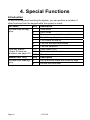
1
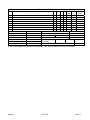
USER GUIDE
HARDWIRED
CONTROL UNIT
Contents
1. Introduction ........................................3
Alarm System.......................................3
Keypad.................................................4
Proximity Tags .....................................4
Mains Power Failures...........................7
About this Guide...................................8
2. Everyday Operation ...........................9
Setting the System ...............................9
General Procedure.........................10
Timed Set.......................................11
Final Door Set ................................11
Lock Set .........................................11
Terminated Set...............................11
Silent Set........................................11
Instant Set ......................................11
Keyswitch Set.................................12
Forbikobler Keypad Set..................12
Investigating Setting Problems...........13
Detector Active...............................13
Other Problems ..............................14
Unsetting the System .........................15
General Procedure.........................15
Keyswitch Unset.............................15
Aborting False Alarms ................... 16
3. After an Alarm.................................. 17
Responding to a Fire Alarm............... 17
Responding to other Alarms .............. 17
4. Special Functions............................ 18
Introduction........................................ 18
Viewing Alerts.................................... 19
Omitting Zones .................................. 20
Normal Alarm Zones...................... 20
24-hour Zones ............................... 20
Requiring User Code before
Installer Code .................................... 21
Reading the Log ................................ 21
Turning the Chime On and Off .......... 22
Testing the Sounders ........................ 22
Testing Zones.................................... 23
Setting up Users ................................ 23
Access Codes ............................... 24
Proximity Tags............................... 26
Setting Time and Date....................... 26
Appendix. Log Messages ................... 27
Your Installation .................................. 32
9651 Hardwired Control Unit User Guide.
This document applies to control panels using software version 4.03.xx.
© Cooper Security Ltd. June 2007
Every effort has been made to ensure that the contents of this book are correct. However, neither the authors
nor Cooper Security Limited accept any liability for loss or damage caused or alleged to be caused directly or
indirectly by this book. The contents of this book are subject to change without notice.
Printed and published in the U.K.
Page 2
11772233
1. Introduction
Alarm System
The alarm system described in this book comprises a control unit (model
9651), one or more keypads, and various detectors. The control unit houses a
main controller, power supply, stand-by battery and an optional
communication device. It is normally fitted in a safe place out of sight (for
example, under the stairs).
The detectors are installed in various places, or zones, around the premises.
If something triggers a detector, the detector signals this to the control unit.
How the control unit reacts depends on whether the system is set or unset.
• When set, the control unit raises an alarm whenever a detector is
triggered. The alarm might be a bell or strobe on the outside of your
premises, or it might be a silent signal over the telephone line to an Alarm
Receiving Centre (ARC).
• When unset, the system does not raise an alarm if a detector is triggered.
•
Your installer can program the control unit so that you can set the system
to one of four levels: A, B, C or D. Level A protects the whole of the
premises covered by the detectors. Levels B, C and D each protect part
of the premises while the rest is in use. You cannot set more than one
level at the same time.
The control unit raises an alarm when a detector in a set level is triggered.
Your installer allocates detector zones to levels during installation. Refer to
the table on page 32 to see how zones are allocated.
Your premises may be fitted with 24-hour zones and panic alarm zones. If
these zones are triggered, the system will raise an alarm even if no level is
set. 24-hour zones are often used to protect (for example) emergency fire
exits.
11772233
Page 3
1. Introduction
Keypad
Your alarm system is fitted with a 9930 or 9940 keypad, from which you can
set and unset the system. Figures 1 and 2 show the main features of these
keypads. Refer to "4. Special Functions" on page 18 for information about
other functions available from them.
The system will not accept commands from the keypad until you identify
yourself with an access code or proximity tag. The system can store up to 50
access codes, which may contain four or six digits1, giving secure access for
up to 50 users.
If you enter an incorrect code, press X to clear the display and try again. If you
enter an incorrect code four times, all keypads will be locked for 90 seconds.
If you do not enter a command within 20 seconds, the system leaves
command mode. You will need to enter your code again to continue.
Your installer may have set up your system to hide status information2. If so,
the display and lamps show no information until you identify yourself. This
feature is designed to make life more difficult for intruders.
Proximity Tags
So that you do not have to remember access codes, your installer may have
fitted your keypads with a device that reads proximity tags. These tags are
small slips of plastic that have electronic circuitry built into them.
When you hold a tag against a suitably equipped keypad, the circuit inside the
tag emits a radio code that the keypad reads. Each tag has a unique code. If
the alarm system recognises the tag, it allows you to do almost anything that
you could do with an access code. If the tag is not recognised, you cannot use
the alarm system. When presenting a tag to a 9930 keypad, make sure that it
is touching the sensitive area to the left of the display (Figure 1). The 9940
keypad has a proximity coil that makes the whole case sensitive to tags.
You can program the system to recognise up to 49 tags. U01, the master
user, can only be assigned an access code – a proximity tag cannot be
assigned to this user. For instructions, refer to page 25.
1
2
Page 4
Installer Command 56
Installer Command 28
11772233
1. Introduction
These may show nothing until you enter a user code.
Sensitive area
Present
proximity tags
by touching
them to this
area.
Alert lamp (see page 19)
Flashes to highlight
unacknowledged alarm,
fault or tamper conditions.
Glows for acknowledged
conditions.
Goes out when all
conditions are rectified.
Service lamp
Glows if the
system needs
an Installer
reset.
Mains lamp
Glows when
using mains
power.
Flashes when
using stand-by
battery.
2-line 16-digit liquid
crystal display
The first line shows:
- unset: time and date
- set: level(s) .
The second line shows
Installer-configured text,
often the control unit
model number.
The display may show
only time and date until
a user is identified.
IMPORTANT NOTE
Level selection
keys
Press to select
levels.
Exit key
Press to
cancel a
command
sequence.
Enter key
Press to
confirm a
command
sequence.
Dual key alarms
Pressing two keys
together can initiate
alarms if these are
enabled (see page 32).
Panic
Press 1 and 3 together.
Medical assistance
Press 4 and 6 together.
Fire
Press 7 and 9 together.
Figure 1. 9930 LCD Remote Keypad
11772233
Page 5
1. Introduction
These may show nothing until you enter a user code.
Alert lamp (see page 19)
Flashes to highlight
unacknowledged alarm,
fault or tamper conditions.
Glows for acknowledged
conditions.
Goes out when all
conditions are rectified.
2-line 16-digit liquid
crystal display
The first line shows:
- unset: time and date
- set: level(s).
The second line shows
Installer-configured text,
often the control unit
model number.
The display may show
only time and date until
a user is identified.
Service lamp
Glows if the
system needs
an Installer
reset.
A
Mains lamp
Glows when
using mains
power.
Flashes when
using stand-by
battery.
B
C
1
2
3
4
5
6
7
8
9
D
Enter key
Press to
confirm a
command
sequence.
0
IMPORTANT NOTE
Dual key alarms
Pressing two keys
together can initiate
alarms if these are
enabled (see page 32).
Panic
Press 1 and 3 together.
Medical assistance
Press 4 and 6 together.
Fire
Press 7 and 9 together.
Figure 2. 9940 LCD Remote Keypad
Page 6
11772233
Level selection
keys
Press to select
levels.
Exit key
Press to
cancel a
command
sequence.
1. Introduction
Mains Power Failures
The control unit indicates mains power failures using alerts. If the supply has
since been restored, the alert will show the condition as inactive. For
instructions on how to view and acknowledge alerts, refer to page 19.
11772233
Page 7
1. Introduction
About this Guide
The rest of this guide tells you how to use the system:
2. Everyday Operation Tells you how to set and unset the system.
3. After an Alarm
Tells you how to switch off the sounders after an
alarm, view what caused the alarm and reset the
system so that it can be used again.
4. Special Functions
Tells you how to use more advanced features, some
of which are available only to the master user.
Page 8
11772233
2. Everyday Operation
During installation, your installer programs the system to create an exit route
and entry route for your premises. When setting the system, you must follow
the exit route. When unsetting the system, you must follow the entry route. If
you stray from these routes, you may cause a false alarm.
Setting the System
There are several different methods for setting the system. Each level can use
a different method, although not all methods are available in all cases. Your
installer will have selected the methods that suit your site best3.
The possible setting methods are:
Timed Set
Final Door Set
Lock Set
Terminated Set
Silent Set
Instant Set
Keyswitch Set
The setting procedure is similar for each method and shown on page 10.
Subsequent sections describe the specifics of each setting method.
If you try to set the system while something is triggering a detector in the
protected area (for example a door or window is still open), the system will not
set (see page 13).
If you find that your detectors generate false alarms immediately after you
leave the premises, this may be because they are detecting air movements
when the exit door is closed. You may need to ask your installer to increase
the Final Exit Settling Time4.
3
4
Installer Commands 39, 62, 72 and 76
Installer Command 182
11772233
Page 9
2. Everyday Operation
General Procedure
To set the system:
1. Secure all doors and windows.
2. At the keypad, key in an access code
(or present a tag).
The display shows (for example):
3.
4.
5.
System OK
Set?
Press the appropriate level key.
Note: If you press y without a level key, the
system sets Level A (Full Set).
If you have omitted a zone (see page 20),
the display shows (for example):
Press y to continue with the zone omitted.
If you do not want to omit it, press X to exit.
During the exit procedure, the keypads give
a continuous exit tone. The tone may be
intermittent if the final door is open.
If you hear an intermittent tone from the
keypads or internal sounder and the final
door is not open, a detector is being
triggered (see page 12).
Leave by the designated exit route.
When you complete the exit procedure in
accordance with the setting method in use,
the system sets and gives a double "beep".
The keypad display shows which level is
set.
Note: If you decide not to set the system, key in your
access code again (or present a tag) to unset it.
Page 10
11772233
Omit Zone 03?
Set? ABCD
Setting ABCD 009
Set ABCD
9x5x
Set A
9x5x
2. Everyday Operation
Timed Set
With Timed Set, the system sets after a programmed exit time has expired.
The time starts when you press a level key, or when you press y to accept an
omitted zone. Your installer will have made the exit time long enough for you
to leave the premises and secure the final door5.
When using Terminated Set (see below), your installer may have
programmed the system to set after the exit time even if the exit terminate
button is not pressed. This ensures your premises are protected if you forget
to press the button.
Final Door Set
Your installer may have programmed the system so that closing the final door
completes the setting sequence. The system sets 7–12 seconds6 after you
secure the final door. There is no fixed exit time.
Lock Set
Your installer may have fitted a special lock so that locking the final door
completes the setting sequence. The lock contains a switch so that the control
unit can sense whether the lock is open or closed. The system sets seven7
seconds after you lock the final door. There is no fixed exit time.
Note: Lock Set is available only for Level A (Full Set).
Terminated Set
Your installer may have fitted an exit terminate button. This is usually outside,
beside the final door, and you press it when you leave. The system sets
seven8 seconds after you press the button. There is no fixed exit time.
Silent Set
Some levels on your system may be programmed for Silent Set. The system
does not give an audible warning when it sets these but it gives a double
"beep" at the end of the exit time to show that it is set.
Note: Silent Set is not available for Level A (Full Set).
Instant Set
The area protected by a level may not need an exit route or final door. With
Instant Set, the system sets as soon as you press the appropriate key, without
5
6
7
8
Installer Commands 44, 65, 75 and 79
Installer Command 182
Installer Command 182
Installer Command 182
11772233
Page 11
2. Everyday Operation
waiting for an exit time. The system gives a double "beep" to show that it is
set.
Note: Instant Set is not available for Level A (Full Set).
Keyswitch Set
If your system is fitted with a keyswitch, you can use it to set the system. If it
is a three-position keyswitch in a single system, you can use it to set Level B.
The keyswitch initiates setting, which then completes in accordance with the
programmed exit mode. You do not need to enter an access code or present
a tag.
Forbikobler Keypad Set
Your system may be programmed to use a special type of entry or exit zone
called a Forbikobler zone. The word "forbikobler" means "bypass" in Danish.
These zones are used to connect external keypads or access controllers.
If an exit is programmed as a Forbikobler zone with an external keypad, a
trigger from the keypad within the exit time stops the timer and sets the
system.
Page 12
11772233
2. Everyday Operation
Investigating Setting Problems
This section offers general guidance. If you need assistance to resolve a
problem, contact your installer.
Detector Active
If something is triggering a detector at the end of the exit procedure, the
system will not set. Depending how your installer has set up the system9,
internal or external sounders may operate. The display shows which zone (or
zones) is active.
To set the system:
1.
2.
3.
4.
5.
9
Enter your access code (or present your tag) to
silence any sounders.
Go to the zone shown on the display (see
example) and find out what is triggering the
detector. If possible, remedy the fault.
Return to the keypad and set the system again.
If no other detectors are active, the system sets.
If other detectors are active, repeat steps 1 to 3.
If the system still will not set, call your installer.
Zone Open
Zone 03
Z03
Installer Command 27
11772233
Page 13
2. Everyday Operation
Other Problems
The system informs you of problems through alerts. These are warnings
communicated through the keypad display and lamps. If your system is set up
to hide status information after 30 seconds10, enter an access code or present
a tag to activate the keypad display and lamps.
Depending on the nature of the problem, you may need to reset the system or
call an installer to do this for you (see page 17). Your installer may have set
up your system to enable you to override some faults11, in which case you will
be able to set the system while the fault is still present. If the display shows
"Set" underneath the alert message, press y to continue with setting.
If an installer reset is required, the control unit lights the s lamp and the
keypad sounds a repeating "beep" to warn you. If the fault disappears, the
lamp goes out but the tone continues until you enter your access code. If the
fault persists and cannot be overridden, the display shows "Call Installer".
A mains power failure is an example of a technical fault that may be resolved
without intervention in the alarm system. A stand-by battery failure is an
example of a technical fault that requires an installer to visit.
If an alert indicates a communications failure (for example, "Plugby Line Fail"),
you may be able to set the system but then it may not be able to report any
alarms to the ARC.
For more information on viewing and acknowledging alerts, see page 19.
10
11
Page 14
Installer Command 28
Installer Commands 134 to 140
11772233
2. Everyday Operation
Unsetting the System
WARNING: If you enter your premises and an internal alarm
starts, there may be an intruder.
You can unset the system from a keypad or keyswitch.
When you open an entry door, the system starts an entry timer. There are four
entry timers so that different entrances can use different times. During the
entry time, the keypads give a "galloping" entry tone to warn you that the timer
is running. If you exceed the entry time, an alarm will occur. Your installer will
have ensured that the entry time for each entrance is long enough for you to
enter by the designated entry route, get to the keypad and unset the system.
If an entry door is fitted with a lock switch, the keypad gives a continuous exit
tone when you unlock it and, if you lock it again, the system remains set; it is
only when you open the entry door that the entry timer starts and the keypads
give the entry tone.
General Procedure
To unset the system:
1. Enter through the designated entry door
and go to the keypad.
2.
As you enter the premises, the system
starts the entry timer and the keypads
give the entry tone.
Key in an access code (or present a tag).
All set levels are unset.
The entry tone stops and the system
gives a double "beep".
The system is now unset.
Keyswitch Unset
If your system is fitted with a keyswitch, you can use it to unset Level A. With
a three-position keyswitch, switching from Part to Off unsets Level B. You do
not need to enter an access code or present a tag.
11772233
Page 15
2. Everyday Operation
Aborting False Alarms
If your system is connected to an ARC and you accidentally cause an alarm,
you normally have at least two minutes before the ARC calls the police. Alarm
Abort12 enables you to cancel a false alarm by entering a valid access code
during this period (which is set by the ARC).
If Alarm Abort is not enabled on your system and you often exceed an entry
timer that is already set to the maximum, ask your installer about Alarm Abort.
12
Page 16
Installer Command 36
11772233
3. After an Alarm
Responding to a Fire Alarm
IMPORTANT: The system gives a fire alarm by
sounding a two-tone warning from the keypads and
alarm sounder. The display shows (for example):
1. Evacuate the premises.
Do not attempt to unset the alarm.
2. If there is evidence of fire, call the Fire Brigade.
3. Only when the premises are safe, proceed as for
other alarms.
Fire Z02 Alarm
9x5x
Responding to other Alarms
When your system raises an alarm other than a fire alarm, you must:
• Unset the system as normal to switch off the sounders and strobes.
• Reset the system ready for further use.
The system logs the zone (or zones) that triggered the alarm and displays
alerts on the keypad display. The first zone is shown automatically when you
unset the system. View the others by pressing Y to accept the Next prompt.
For instructions on viewing and acknowledging alerts, see page 19.
Your system may be configured for various types of reset:
•
User reset. Enter your access code (or present your tag) again to reset
the system. The system gives a double "beep" to confirm that it has reset.
•
Installer reset. If the display shows "Call Installer", contact your alarm
company to arrange a visit.
Remote reset. If the display shows a reset code, write down the code
and call your ARC. You will be asked to verify your identity, the
circumstances and the code. If no intervention is required from an
installer, you will be given a code to enable you to reset the system.
•
11772233
Page 17
4. Special Functions
Introduction
As well as setting and unsetting the system, you can perform a number of
other functions from the keypad while the system is unset:
All Users
Access code (or tag)
plus:
Dual key alarms
(check if these are
enabled, see page 32)
Master User Only
Access code (not tag)
plus:
Page 18
Key
1
2
3
5
7
8
9
1+3
4+6
7+9
Key
4
6
Description
View alerts
Omit zones
Require user code before installer code
Read the log of system events
Turn chime on and off
Test the sounders and strobe
Test the detectors
Panic alarm (PA)
Medical assistance alarm
Fire alarm
Description
Set up access codes and proximity tags
Set the time and date
11772233
4. Special Functions
Viewing Alerts
The system records alarms, faults and tampers as alerts. It usually displays
the first alert automatically when you unset the system but you can view alerts
at any time by pressing 1. Viewing an alert acknowledges it. The Alert lamp
( ) flashes for unacknowledged alerts and glows for acknowledged alerts. If
the condition that caused the alert still exists, the alert message shows
"Active". If the condition no longer exists, the message shows "Inactive".
To view alerts:
1. Key in an access code (or present a tag).
If the lamp is glowing or flashing, there are
3 Problem(s)
alerts. The system may display the first alert or it
Set? ABCD
may show how many alerts exist (for example):
2. Press 1 to view the alerts.
The display shows the first alert (for example):
MAINS Fail
Inactive
3.
4.
Here, "Inactive" indicates that the mains power
supply has since been restored.
Press y for "Next" to view the next alert.
The display shows the second alert (for example):
Here, "Inactive" indicates that the tamper switch
has since been closed.
Press y for "Next" to view the next alert.
The display shows the third alert (for example):
Next
Lid Tamper
Inactive
Next
Battery Missing
Active
Next
Here, "Active" indicates that the battery is still
missing. The s lamp will also be lit and there will
be an intermittent audible warning.
5.
If you have viewed all alerts and installer action is
required (for example, to fit a new battery), the
display shows:
In this case, contact your alarm company.
6.
If you have viewed all alerts and no installer action
is required, the display shows date and time (for
example):
In this case, use the system as normal.
11772233
Call Installer
9x5x
18/04/2005 14:45
9x5x
Page 19
4. Special Functions
Omitting Zones
Your system may be programmed so that you can omit individual detectors.
This enables you to ignore alarms coming from faulty detectors in non-critical
positions. Refer to the table on page 32 to see which zones can be omitted in
your system.
To omit a zone:
1. Key in an access code (or present a tag).
2. Press 2.
This display shows:
Omit Zone?
3.
4.
Press the number of the zone you want to
omit (for example, press 07 to omit zone
7) and then press y.
The sounder gives a double "beep" and
the display shows the zone number
followed by an "o":
If you try to omit a zone for which this is
not allowed, the display shows an "X"
after the zone number.
Press X to exit.
Omit Zone 07o
Omit Zone 07X
Note: To include a zone that was omitted, follow the same procedure.
Pressing y toggles between omit and include.
Normal Alarm Zones
When you next set the system, a message asks you to confirm that you want
to omit the zone. Press y to set the system with the zone omitted. Omission is
not permanent: when you next unset the system, the control unit reinstates
the zone. You must omit the zone each time you prepare to set the system.
24-hour Zones
When you next set the system, there is no message to confirm the omission.
24-hour zones (for example, protecting a fire door) remain omitted until you
reinstate them from the keypad:
1. Key in an access code (or present a tag).
2. Press 2 followed by the zone number and then y.
3. Press X to exit.
Page 20
11772233
4. Special Functions
Requiring User Code before Installer Code
You can specify that a user code must be entered before the installer code to
access the installer menu. This enables you to supervise installer activities.
1. Key in an access code (or present a tag).
2. Press 3 to toggle between requiring and
not requiring a user code.
The display shows (for example):
UserCode req=OFF
3.
When you turn user code on or off, the
keypad confirms with a double "beep".
Press y.
Reading the Log
The system keeps a log of the last 700 events. The Appendix on page 27
explains the meaning of the messages that may be logged.
To view the log:
1. Key in an access code (or present a tag).
2. Press 5.
The display shows a message describing the
U01 Change U02
most recent event (here, for example, user 1 has
00:42 18/04/2005
changed the access code for user 2):
3. Press: 1 to see earlier events
3 to see later events
4 to see the first event
6 to see the last event
4. Press X to stop using the log.
Note: Neither an installer nor a user can erase the log.
In the log, user codes are represented by numbers as follows:
U00
U01
U02 to U50
U50
U51
Installer
User 1
Users 2 to 50
Guard code (if set up)
Duress code
11772233
U52
U53
U55
U56
U59
Control unit
Idle
Keyswitch
Remote reset
Forbikobler
Page 21
4. Special Functions
Turning the Chime On and Off
Your system may be programmed so that a chime tone sounds when certain
doors are opened while the system is unset. You can turn this on and off.
1. Key in an access code (or present a tag).
2. Press 7 to toggle chime on and off.
The display shows (for example):
Chime
=
ON
When you turn chime on, the keypad
confirms with a double "beep".
3.
Press y.
Testing the Sounders
You can test that the sounders and strobe are working. The system turns on
each sounder in turn for three seconds.
Note: The strobe flashes for 10 seconds to give you time to see it.
1.
2.
Key in an access code (or present a tag).
Press 8 to start the test.
The display shows:
Test: Bell
Test: Strobe
Test: Speaker
Test: Keypad
Page 22
11772233
4. Special Functions
Testing Zones
You can set the system so that it will allow you to walk around and test each
of the detectors (a walk test). Do this when the premises are empty to avoid
other people triggering movement detectors before you do, which would
confuse the results of the test. If a detector fails the test, contact your alarm
company and ask them to check the system.
Notes:
1.
2.
You can abandon the test at any time by pressing y.
You cannot test 24-hour zones (including Fire and PA) or tamper circuits with this
command. If you wish to test them, contact your alarm company.
To test zones:
1. Key in an access code (or present a tag).
2. Press 9.
This display shows:
3.
4.
Walk around your premises and trigger the
detectors in turn (excluding 24-hour and PA
zones).
When you trigger a detector, the keypad and
internal sounder give a short tone.
The display shows 'A' for alarm, followed by the
zone number of the detector.
If you trigger more than one detector, the display
shows the zone numbers in turn.
Press y to stop the test when you have triggered
all the detectors.
Walk Test
A: Zone 02
Setting up Users
Note: Only the master user (U01) can set up users.
The system can store up to 50 different user access codes. For security, you
should give one code to each person who has responsibility for setting and
unsetting the system: do not allow users to share codes.
To distinguish users and conceal their access codes, the log shows each user
as a number (for example, U02). You can store a user name for each access
code, which is visible when the code is modified but not displayed or logged.
11772233
Page 23
4. Special Functions
When the system is delivered from the factory, all access codes are set to
default values. Depending how your installer has set up the system13, access
codes may contain four or six digits. The default for the master user (U01) is
"1234" when four-digit codes are in use and "123456" when six-digit codes
are in use. The master user should change this immediately to a code known
to no one else.
The other defaults are "X002" for U02 through to "X050" for U50. As default
codes cannot be used to set or unset the system, or use any of its special
functions, they do not need to be changed until they are assigned to users.
Do not assign access codes starting with zero. That is, use codes within the
range 1000–9999 (or 100000–999999 if using six-digit codes).
Access Codes
To set the access code for a user:
1. Key in the master user access code.
2. Press 4.
The display prompts for the access code that you
wish to change:
3.
4.
Key in the code (for example, X023 – the default
code for User 23) and press y.
The display shows the user number (U23) and the
user name (User 23):
If you wish to change the name, use the keypad as
described in Changing User Names on page 25.
When the user name is correct, press y.
The display shows (for example):
5.
Key in the new access code, starting with a number
in the range 1–9. The display shows (for example):
6.
Press y to store the new access code
(in this case, 4926).
13
Page 24
Installer Command 56
11772233
Old Code=
----
U23:User 23
User 23:
----
User 23 = 4926
4. Special Functions
To delete an access code:
1. Follow the procedure for setting an access code.
2. In step 5, key in "0000".
Changing User Names
The system can store up to 12 characters for each user name, including
spaces and punctuation marks. The default names are in the form User nn.
You can change the name when you set the access code. In step 3 of the
procedure on page 24, the display shows the current user name with a
flashing cursor under the first letter. Enter letters one at a time in the same
way as when texting on a mobile phone, by repeatedly pressing a key until the
required letter is displayed. To move right, press C. To move left, press D.
1
2
3
4
5
6
None
ABCÆÅÄ
DEF
GHI
JKL
MNOØÖ
7
8
9
0
C
D
PQRS
TUV
WXYZ
Space ' ( ) : . - ! &
Move right
Move left
To delete a whole name, move to the first character and press D.
When you have entered the name, press y to continue with setting the code.
Assigning a Duress Code
If your system is connected to an ARC, you may want to give a duress code
to some users as well as their access code. The duress code is designed to
send a silent communication if a user is forced to unset the system by an
intruder. It has to be enabled by your installer14. When unset with a duress
code instead of an access code, the system appears to respond normally but
the control unit sends a silent communication to the ARC. A user who has the
duress code can use any of the system's facilities.
The duress code is assigned to U51 and, when the control unit leaves the
factory, is inactive and set to "X051". To activate it, assign a new code to U51
using the same procedure as for assigning codes to other users.
14
Installer Command 49
11772233
Page 25
4. Special Functions
Proximity Tags
Each normal user (Users 2 to 50) can have a tag, an access code or both.
You cannot assign a tag to the master user (U01), the installer (U00), or the
duress code (U51).
You set up a tag in a similar way to an access code (see page 24). Instead of
entering a new access code for the user, present the tag. The system learns
the identity of the tag and links it to the user number. The keypad confirms
that the tag has been learned with a double "beep".
You delete a tag in exactly the same way as an access code. When you key
in "0000", it deletes both the tag and access code for the displayed user.
Setting Time and Date
Note: Only the master user (U01) can set the system time and date.
The control unit contains an internal clock/calendar that runs as long as there
is power present (mains or stand-by battery). The system uses this clock to
record the time and date of events in the log. If the mains power supply fails
while the stand-by battery is low, you may need to correct the time and date. If
your country uses summer and winter time, you may need to adjust the time.
To set the time and date:
1. Key in the master user access code.
2. Press 6.
The display shows the date.
D04 M11 Y99
3.
4.
5.
6.
7.
Key in two digits for the day, followed by y.
Key two digits for the month (01 for January to 12
for December), followed by y.
Key in two digits for the year, followed by y.
The display shows the time.
Key in two digits for the hour followed by y. Use
the 24-hour clock.
Key in two digits for the minutes, followed by y.
The display shows the new time and date:
Page 26
11772233
H17 M02
18/04/2005 14:45
9x5x
Appendix. Log Messages
Message
Message
Meaning
AC Fail
Mains power supply failed
AC Restore
Mains power supply restored
Al Conf Dis K== Alarm confirmation disabled by
lock switch
Al Confirm Z== Confirmed alarm on zone ==
Alarm Abort
User aborted alarm
AntiMask Al Z== Anti-mask alarm on zone ==
AntiMask Rs
Anti-mask alarm on zone ==
Z==
reset
AntiMask Tp Z== Tamper on anti-mask zone ==
AUX DC Fail
Auxiliary power failed
AUX DC Fail
Auxiliary power restored
Rstr
Bad Checksum Control unit memory corrupted
Batt Flt Rstr
Battery reconnected
Batt Load Fail
Battery failed load test
Batt Missing
Battery disconnected
Bell Tamper
Sounder tampered with
Bell Tamper Rst Sounder tamper reset
Burg Z== Alarm Intruder alarm on zone ==
Burg Z== Rstr
Intruder alarm on zone ==
reset
Codes Defaulted Access codes returned to
default values
Comms Fail
Communications failure
Defaults Loaded Default values loaded for all
commands
EEPROM Fail
Control unit memory damaged
F== Missing
Forbikobler keypad
disconnected
F== Restore
Forbikobler keypad
reconnected
F== Tamper
Forbikobler keypad tampered
with
Fire Reset
Fire alarm reset
Fire Z== Alarm Fire alarm on zone ==
Fire Z== Rstr
Fire alarm on zone == restore
Forbi I/F Tamper Forbikobler interface tampered
with
Forbi Lp Tamper Forbikobler loop tampered with
Fr K== Alarm
Fire alarm started at keypad
==
Meaning
Frb I/F Tamp Rst Forbikobler interface tamper
reset
Frb Lp Tamp Rst Forbikobler loop tamper reset
Global T.Restore Global zone tamper alarm
reset
Global Tamper Global zone tamper alarm
K== Excess
Incorrect access code entered
Keys
more than four times at keypad
==
K== Missing
Keypad == disconnected
K== Restore
Keypad == reconnected
K== Tamper
Keypad == tampered with
Key Box Cls Z== Keybox on zone == closed
Key Box Opn
Keybox on zone == open
Z==
Key Sw Set #
System set by keyswitch on
level n
KeySw Unset # System unset by keyswitch on
level n
Lid Tamp
Control unit lid tamper reset
Restore
Lid Tamper
Control unit lid tampered with
Low Batt Rstr
Low battery detected on
control unit
Low Batt Rstr
Low battery reset on control
Z==
unit
Md K== Alarm
Medical alarm started at
keypad ==
PA K== Alarm
Panic alarm started at keypad
==
PA Z== Alarm
Panic alarm started in zone ==
PA Z== Rstr
Panic alarm reset in zone ==
Set Fail Z==
System failed to set because
of fault in zone ==
Smk Det Alm
Smoke detector alarm in zone
Z==
==
Smk Det Res
Smoke detector alarm reset
Z==
zone ==
Soak Fail Z==
Soak test failed in zone ==
System
System rearmed after an alarm
Rearmed
System Startup Power applied to system
11772233
Page 27
Appendix
Message
Log Messages
Meaning
System Tamp
System tamper reset
Rst
System Tamper System tamper
Tamper F== Rstr Forbikobler keypad == tamper
reset
Tamper K==
Keypad == tamper reset
Rstr
Tamper Z==
Zone == tampered with
Tamper Z==
Tamper in zone == during the
day
Tamper Z== Rstr Zone == tamper reset
Tech Z== Alarm Technical alarm in zone ==
Tech Z== Rstr
Technical alarm in zone ==
reset
Tel Line Fault
Line fault on telephone line
Tel Line Rstr
Line fault reset on telephone
line
U== # Set
User == set level #
U== # UnSet
User == unset level #
U== Change
User == changed access code
U==
for user ==
U== Delete U== User == deleted access code
for user ==
U== Duress
Duress code entered by user
==
U== Off-Site
Installer exited from
programming mode
U== On-Site
Installer entered from
programming mode
U== System
User – reset system
Reset
U== Time/Date Time and date user reset the
system
U== Z== Omit
User omitted zone ==
U== Z== Unomit User unomitted zone ==
UserCode req off No user code before installer
code
UserCode req on User code before installer
code
XT ACFl Rst Z== Mains power supply restored
in zone ==
XT ACFl Z==
Mains power supply failed in
zone ==
XT BatFl Rst
Battery reconnected in zone
Z==
==
XT BatFl Z==
Battery fault in zone ==
Page 28
Message
Meaning
XT Fault Z== Rst
XT Fault Zone
==
XT PwrFl Rst
Z==
XT PwrFl Z==
Z== Lock Out
Zone of type ‘Fault’ reset
Zone of type ‘Fault’ active
Z== Lock Out
Rst
11772233
Power output fault reset in
zone ==
Power output fault in zone ==
The system locked out the
zone when attempting to rearm
a the end of the bell run time.
The system restored a locked
out zone.
NOTES
11772233
Page 29
NOTES
Page 30
11772233
NOTES
11772233
Page 31
Your Installation
Zone
1
2
3
4
5
6
7
8
Company Name
Control Unit Model
Exit Time
Bell Duration
Engineer Reset
Communicator Fitted
Meets DD243: 2004
Description
A
A
B
Contact Number (Day)
Contact Number (Night)
B
C
C
D Omit Chime
Allow
Entry
Time
D
Dual Key
PA
Fire
Enabled?
Meets PD 6662 / prEN 50131-1: 2004
Medical
Note: If this table has not been completed, ask your Installer for the information.
Page 32
11772233
Issue 1