1
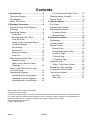
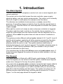
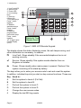
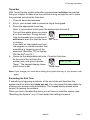
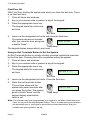
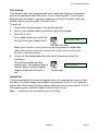
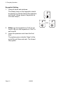
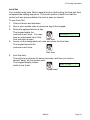
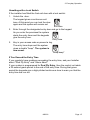
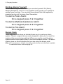
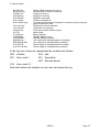
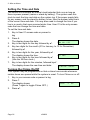
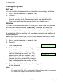
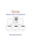
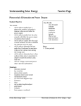
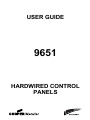
USER GUIDE
9651
HARDWIRED CONTROL
PANELS
Contents
1. Introduction ........................................3
The Alarm System................................3
The Keypad..........................................3
About This Guide .................................5
2. Everyday Operation ...........................6
How Do I Know if the System is
Working?..............................................6
Setting the System ...............................6
Timed Set.........................................7
Exceeding the Exit Time ..................7
Final Door Set ..................................8
Using an Exit Terminate Button
to Set the System.............................8
Part Setting ......................................9
Instant Set ........................................9
Keyswitch Setting...........................10
Lock Set .........................................11
If the System Will Not Set ..................12
Detector Active...............................12
Other Faults (Service Lamp
Glowing) .........................................12
What To Do When Service and
Line Fault Glow ..................................13
Unsetting the System .........................14
Unsetting From a Keyswitch...........14
Unsetting From the Keypad ...........14
Unsetting with a Lock Switch..........15
If You Exceed the Entry Time ........ 15
Starting Alarms Yourself.................... 16
Duress Code ..................................... 16
3. After an Alarm.................................. 17
Fire Alarm.......................................... 17
Disarming the System ....................... 17
Resetting the System ........................ 17
Customer Reset............................. 18
Remote Reset ............................... 18
4. Special Functions............................ 19
Introduction........................................ 19
Omitting Zones .................................. 19
Access Codes ................................... 20
Duress Code ................................. 20
Changing Access Codes ............... 21
Proximity Tags............................... 22
To Add a Tag................................. 22
To Delete a Tag:............................ 23
Using the Log .................................... 24
Table 1. Log Event Codes ............. 24
Setting the Time and Date................. 26
Turning the Chime On/Off ................. 26
Testing the System............................ 27
Bell Test ........................................ 27
Walk Test ...................................... 27
9651 Hardwired Control Panel User Guide.
© Cooper Security Ltd. 2004
Every effort has been made to ensure that the contents of this book are correct. However, neither the authors
nor Cooper Security Limited accept any liability for loss or damage caused or alleged to be caused directly or
indirectly by this book. The contents of this book are subject to change without notice.
Printed and published in the U.K.
Part No. 496930 Issue 2
Page 2
496930
1. Introduction
The Alarm System
The 9651 alarm system comprises a control unit, one or more keypads, and
various detectors.
The control unit is a box that houses the main controller, power supply,
stand-by battery, and any remote communicator. The control unit is normally
fitted out of sight in a safe place (for example under the stairs).
The detectors are installed at various places, or zones, around the
premises. If something triggers a detector then the detector signals back to
the control unit. How the control unit reacts depends on whether the system
is set or unset.
When set the control unit raises an alarm whenever a detector is triggered.
The alarm might be a bell or strobe on the outside of your premises, or it
might be a silent signal from the communicator over the telephone line to a
recipient. When unset the system does not raise an alarm if a detector is
triggered.
The system provides different setting Levels, labeled A, B, C and D. Level A
sets the whole system, protecting all of the premises covered by the alarm
system. Levels B, C and D set part of the system, protecting part of the
premises while the rest is in use. The system raises an alarm when a
detector belonging to a set Level is triggered. The Installer allocates zones to
Levels B, C and D during installation. Ask your Installer to tell you which
zones are allocated to each Level.
Your premises may be fitted with 24 hour zones and panic alarm zones. If
these zones are triggered the system will raise an alarm whether or not any
Level is set.
The Keypad
Your alarm system is fitted with a 9930 liquid crystal display (LCD) keypad.
From the keypad you can set and unset the system, read the event log and
make minor changes to the way the system operates.
You must enter an access code or present a “proximity tag" (simply called a
"tag" in the rest of this book) at the keypad before the system will accept
commands from the keypad. If you make a mistake with your access code
press X to clear the display and start again. The system can store up to 16
different access codes and/or tags, providing secure access for 16 users.
Figure 1 on the next page shows the keypad in detail.
496930
Page 3
1. Introduction
1. Line Fault LED
2. Service LED
3. Power LED
4. Level setting
keys.
5. Omit key.
6 Enter Key
7 Fire alarm keys.
Press 7 and 9
together.
8. Medical
assistance keys.
Press 4 and 6
together.
9. Optional
programmable
panic alarm keys.
Press 1 and 3
together.
10. 16 digit Liquid
Crystal Display
(LCD).
1
4
“Proximity” Tag
Reader Area
Figure 1. 9930 LCD Remote Keypad.
The display shows the state of detector zones, the anti-tamper wiring, and
other information as necessary. In addition:
f
Line Fault. Glows steadily if the connected telephone line is not
working correctly.
s
Service. Glows steadily if the system needs attention from an
Engineer or Installer.
a
Power. Glows steadily when mains power is present. Flashes if the
system is working off its stand-by battery.
The keys allow you to enter your access code to set and unset the system.
In addition, individual keys let you start or stop various functions. These are:
Key Used to:
A
Set the system to Level A (Full Set).
B
Set the system to Level B.
C
Part set the system to Level C.
D
Part set the system to Level D
4
Change the user access codes.
5
Display the last 250 log events.
Page 4
496930
1. Introduction
6
7
8
9
X
Y
Set the internal clock/calendar, which provides a time stamp on log
entries.
Enable or disable the Chime facility.
Start a test of the sounders and strobe.
Start a test of the detectors. (See "4. Special Functions".)
Omit individual zones or start again if you make a mistake when
entering access codes.
Enter programming and setting/unsetting commands.
About This Guide
The rest of this guide tells you how to use the system in more detail:
2. Everyday Operation Describes how to set and unset the system.
3. After an Alarm
Tells you how to switch off the sounders after an
alarm, how to see what caused the alarm, and how
to reset the system so that it can be used again.
4. Special Functions
Tells you how to use the more advanced features
of the system.
496930
Page 5
2. Everyday Operation
There are several different ways of setting the system. For all methods
(except using a keyswitch) you must enter your access code or present a
tag at the keypad. The keyswitch method uses a key in a special switch fitted
to your premises. "Setting the System" below describes each method. Ask
your Installer to provide the method that suits your site best.
During installation the Installer programs the system to create an exit route
for your premises. When setting the system you must follow this route to
leave the premises. You must also follow a specified entry route when
going into the premises in order to unset the system. If you stray from these
routes you may cause a false alarm.
How Do I Know if the System is Working?
The a lamp always glows when the mains power is present. If the a lamp
flashes slowly then mains power is off, and the system is working from its
internal battery. If the a lamp is off then the system is dead.
When the system is set, the keypad display shows which Level is set.
However, the Installer can program the system to hide this display. Ask your
Installer how the system is set up.
If you wish to test the system and its detectors, see "4. Special Functions Testing the System" on page 27.
Setting the System
Your alarm system provides several different methods for setting:
Timed Set.
Final Door Set.
Exit Terminate Button.
Part Setting (including Instant Set or Silent Set).
Keyswitch Setting.
Lock Set.
Ask your Installer which method is fitted, and then use the following pages
for detailed instructions.
Page 6
496930
2. Everyday Operation
Timed Set
With Timed Set the system sets after a programmed exit time has expired.
Ask your Installer to make sure the exit time is long enough for you to leave
the premises and close the final door.
1. Close all doors and windows.
2. Key in your access code or present a tag at the keypad.
3. Press the appropriate Level key.
Note: If you press Y at this point the system sets at Level A.
The exit time starts when you press
Y or the Level key. During the exit
Setting A 009
time the keypads give a continuous
exit tone to warn you that the timer Exit Tone
is running.
If you hear an interrupted tone from
the keypads or internal sounder then
something is triggering one of the
detectors. (See also "If The System
Will Not Set" on p12.)
4. Leave via the designated exit route. Close the final door.
At the end of the exit time the
Level A set
system sets, and gives a double
"beep". The keypad display shows
"beep beep"
which Level is set.
Note: If you change your mind about setting the system then key in your access code
again.
Exceeding the Exit Time
If something is triggering a detector at the end of the exit time then the
system starts an alarm and does not set. You can cancel this false alarm by
entering your access code immediately. The keypad display shows which
zone(s) is causing the problem.
When you have cancelled the alarm you will have to reset the system (see
"Resetting the System" on p17) and restart the setting procedure.
496930
Page 7
2. Everyday Operation
Final Door Set
With Final Door Setting the system sets when you close the last door. There
is no fixed exit time.
1. Close all doors and windows.
2. Key in your access code or present a tag at the keypad.
3. Press the appropriate Level key.
The keypad starts the continuous
exit tone.
Setting A --Exit tone
Leave via the designated exit route and close the final door.
The system sets seven seconds
after you close the door and gives
Level A set
a double "beep".
"beep beep"
The keypad display shows which Level is set.
4.
Using an Exit Terminate Button to Set the System
An Exit Terminate Button is usually a button mounted outside the premises
by the final door. Pressing the button completes setting the system.
1. Close all doors and windows.
2. Key in your access code or present a tag at the keypad.
3. Press the appropriate Level key.
The keypad starts the continuous
Setting A --exit tone.
4.
5.
Exit tone
Leave via the designated exit route. Close the final door.
Press the exit terminate button.
The exit tone stops and the
Level A
system sets seven seconds after
you press the button. The system
"beep beep"
gives a double "beep" and the
keypad display shows which
Level is set.
set
Note: The Installer may have programmed your system to set after a fixed time even
if you do not press the exit terminate button. This is to make sure your premises
are protected even if you forget to press the exit terminate button. Ask your
Installer how your system is set up.
Page 8
496930
2. Everyday Operation
Part Setting
The Installer may have programmed your system so that you can protect
part of the premises while the rest is in use. Level keys B, C and D give
different part set areas. Level key A always sets the full system. Ask your
Installer which zones keys B, C and D cover.
To part set:
1. Close doors and windows in the protected area.
2. Key in your access code or present a tag at the keypad.
3. Press B, C or D.
The keypad starts the quiet Part
Setting B 009
Set exit tone (see "Instant Set").
Part set exit tone
Note: Some Levels on your system may be programmed for Silent Set.
When setting these Levels the system does not give any tones from the
keypads or internal sounder.
4.
Leave via the designated exit route and if necessary close the
final door.
The exit tone stops and the
Level B Set
system sets. The system gives a
double "beep" and the keypad
"beep beep"
display shows which Level is
set.
Instant Set
The area protected by a part set system may not need an exit route or final
exit door. For these areas the Installer may program the B, C or D keys as
Instant Set. With Instant Set the system sets as soon as you press B, C or D.
The system gives a double "beep" to show that it is set.
Note:
Instant set is not available for key A (Full Set).
496930
Page 9
2. Everyday Operation
Keyswitch Setting
1. Close all doors and windows.
The Ready lamp on the keyswitch should
be glowing to indicate that all the detectors
are closed. (Some types of keyswitch do
not have lamps.)
Armed
Ready
Full
Off
Part
Armed
Ready
Full
2.
3.
Either turn the keyswitch to "Full" to set
Level A Or turn the keyswitch to "Part" to
set Level B.
Leave the premises and close the final
door.
The system gives a double "beep" at the
end of the exit time and sets. The Armed
lamp glows.
Page 10
496930
Off
Part
Armed
Ready
OR
Full
Off
Part
2. Everyday Operation
Lock Set
Your installer may have fitted a special lock so that locking the final exit door
completes the setting sequence. (The lock contains a switch so that the
control unit can sense whether the lock is open or closed).
To use Lock Set:
1. Close all doors and windows.
2. Key in your access code or present a tag at the keypad.
3. Press the appropriate Level key.
The keypad starts the
Setting A --continuous exit tone. You may
hear an interrupted tone if the
Exit tone
final exit door is open.
4. Leave via the designated exit route and close the final door.
The keypad sounds the
continuous exit tone.
Exit tone
5.
Lock the door.
The exit tone continues for seven seconds, and then you hear a
double "beep" as the system sets.
The keypad display shows
Level A Set
which Level is set.
"beep beep"
496930
Page 11
2. Everyday Operation
If the System Will Not Set
Detector Active
If you try to set the system while something is triggering one of the detectors
in the protected area (for example a door or window is still open) then the
keypads or internal sounder will give an interrupted tone and the display will
show the zone number of the detector.
1. Go to the zone shown on the display and find out what is
triggering the detector. If possible remedy the fault.
2. Return to the keypad and set the system again.
If no other detectors are active the system sets.
3. Repeat steps 1 to 2 if the display shows other zones.
4. If you still cannot set the system then call the Installer.
Other Faults (Service Lamp Glowing)
If the control unit detects a technical fault then it lights the s lamp on the
keypad to warn you that there is a problem. (If the fault disappears the
control unit switches the s lamp off.) The keypad sounds a soft intermittent
"beep" to draw your attention. This attention tone continues even if the s
lamp goes off. To indicate the nature of the fault the control unit makes an
entry in the log and displays a short text warning on the keypad when you
next enter an access code to set the system.
To acknowledge the warning, press Y. The control unit removes the warning
message from the display and silences the attention tone. You can carry on
and set the system.
For example, if the mains supply is interrupted then s on the keypad glows
and the a lamp flashes. When you next enter your access code to set the
system the keypad display shows the words:
MAINS Fail
1.
Press Y.
The keypad display shows:
Select ?
2. Carry on and set the system as normal.
If you still cannot set the system after acknowledging a warning then call the
Installer.
Note: If the mains electricity supply fails then you can still set the system. Key in your
access code and press Y then press A, B, C or D followed by Y.
Page 12
496930
2. Everyday Operation
What To Do When Service and Line Fault Glow
If you hear an intermittent tone from the keypad, and both the s and f
lamps glow then your system may have experienced a temporary telephone
line fault.
1. Key in your access code or present a tag
The tone stops and the display may briefly
Plugby line fail
show:
The s and f lamps will continue to glow
for as long as the fault is present.
If the system detects that the fault has been rectified, then the s and f
lamps go off.
If the s and f lamps remain glowing for more than five minutes then call
your alarm service company and report the fault.
You can set the system while the s and f lamps are lit. When setting you
may again briefly see the message "Plugby Line Fail". However, note that if
a telephone line fault is present during an alarm then the system may not be
able to report the alarm.
496930
Page 13
2. Everyday Operation
Unsetting the System
WARNING: If you enter your premises and an internal alarm
starts then there may be an intruder.
Unsetting From a Keyswitch
Turn the keyswitch to OFF. The system unsets immediately.
Unsetting From the Keypad
The system has a programmed entry time. Ask your Installer to make sure
the entry time is long enough for you to enter by the designated entry route,
get to the keypad and unset the system.
The entry time starts when you open the designated entry door. During the
entry time the keypads give a "galloping" entry tone to warn you that the
timer is running.
1. Enter through the designated entry door and go to the keypad.
As you enter the premises the system
starts the entry timer and the keypads
give the entry tone.
Entry tone
2. Key in your access code or present a tag
The entry tone stops and the system
gives a double "beep". The system is
now unset.
"beep beep"
Page 14
496930
2. Everyday Operation
Unsetting with a Lock Switch
If the installer has fitted the final exit door with a lock switch:
1. Unlock the door.
The keypad gives a continuous exit
tone. At this point you can lock the door
again and the system will remain set.
Exit tone
2. Enter through the designated entry door and go to the keypad.
As you enter the premises the system
starts the entry timer and the keypads
give the entry tone.
Entry tone
2. Key in your access code or present a tag.
The entry tone stops and the system
gives a double "beep". The system is
now unset.
"beep beep"
If You Exceed the Entry Time
If you regularly have problems exceeding the entry time, ask your Installer
about "Dual Ply Entry" and "Alarm Abort".
If your system is programmed for Dual Ply Entry, then the control unit adds
a 30 second grace period to the end of the entry time. During that grace
period the keypads give a high pitched continuous tone to warn you that the
entry time has run out.
496930
Page 15
2. Everyday Operation
Starting Alarms Yourself
There are three types of alarm that you can start yourself: PA (Panic),
Medical Assistance, and Fire. Your Installer must program your system to
enable these functions. You can start these alarms from the keypads by
pressing two keys at the same time. Remember:
To start a Panic Alarm:
On a keypad press 1 & 3 together.
To start a Medical Assistance Alarm:
On a keypad press 4 & 6 together.
To start a Fire Alarm:
On a keypad press 7 & 9 together.
Duress Code
There may be a time when an intruder forces you to unset your alarm
system. There is a special duress code designed to allow you to unset the
system while you are being watched. When you use the code the alarm
system sends a silent panic alarm to the communication device. The alarm
system gives no other indication that you are using the duress code.
Note: You must ask your Installer to make sure the duress code facility is available.
To create the duress code see page 20.
Page 16
496930
3. After an Alarm
When your system raises an alarm you must disarm it in order to switch off
the sounders and strobes. The system keeps a record of which zone(s)
triggered the alarms, and shows the zone number(s) on the keypad display.
Once you have disarmed the system, you must reset the system before you
can start using it again.
Fire Alarm
The system gives a fire alarm by sounding a warbling tone from the keypads
and alarm sounder. The display shows the letters "Fire".
1. Evacuate the premises and call the Fire Brigade. Do not attempt to unset
the alarm.
2. When the premises are safe, follow the instructions below.
Disarming the System
If the system is full set then:
1. Go to the keypad via the entry route.
2. Key in your access code or present a tag
The sounders go quiet and the
system gives a double "beep" to
show that it is unset. The
keypad display shows alarm and "beep beep"
the zone number of the first
detector to be triggered. You
may also see the s lamp
glowing.
3. Establish the cause of the alarm.
4. Carry on to reset the system.
Zone 02
Resetting the System
There are three different methods for resetting. You can tell which method
your system uses by looking at the s lamp after an alarm.
•
If the s lamp is off then the system uses Customer Reset. You can
reset the system yourself from the keypad.
•
If the s lamp glows after an alarm then your system uses Engineer
Reset. Call your alarm company and ask for an engineer to visit the
premises to reset the system.
496661
Page 17
3. After an Alarm
•
If the s lamp glows after an alarm and your system is connected to an
communication device then your system may use Remote Reset. Your
alarm company will give you instructions over the phone and a special
code so that you can reset the system from the keypad.
Customer Reset
1. Key in your access code or present a tag and press Y.
The display clears.
2. You can now use your system as normal.
Remote Reset
Before starting this process, make sure you have a pen and paper to hand.
You will need to write down some information shown on the keypad. If you
have not carried out a remote reset before, read the instructions through
before starting.
1. Key in your access code or present a tag
The display shows:
Select?
2. Press Y.
The display shows a four
Reset code = 1234
digit Reset Code.
3. Write down the four digit Reset Code.
Note: that the system will display the Reset Code for 30 seconds and
then return to showing the first detector to alarm. If you miss the
Reset Code repeat steps 1 to 3.
4.
5.
6.
Contact your alarm company.
The company will ask a few questions to make sure you are who
you say you are. They will then ask for the circumstances of the
alarm, and for the Reset Code. If they do not need to send an
Engineer to check the system they will give you an "Anti Code".
Key in the Anti Code on the keypad.
The display clears and the
04/02/00 17:33
Service lamp goes out.
You can now use your system as normal.
Page 18
496930
4. Special Functions
Introduction
From the keypad you can perform a number of other functions, apart from
setting and unsetting the system. These functions are:
[Access code] + X
Omitting zones.
[User 01 Access code] + 4
Changing access codes and user names.
[Access code] + 5
Reading the system log.
[User 01 Access code] + 6
Setting the time and date.
[Access code] + 7
Turning the chime on or off.
[Access code] + 8
Testing the sounders.
[Access code] + 9
Testing the zones.
To use these functions you must key in your access code or present a tag
and then press a number key. The rest of this section describes each
function in turn.
Omitting Zones
Your system may be programmed so that you can omit individual detectors.
Ask your Installer which zones can be omitted.
To omit a zone:
1.
Key in your access code or present a tag and press X.
The display shows:
Omit
2.
Zone?
Press the number of the zone you want to omit
(for example, key in 07 to omit zone 7).
3. Press Y.
The sounder gives a double beep and the
Omit Zone 07o
display shows the zone number followed by an
"o":
Note:
If the display shows a “x” after the zone number then you cannot omit
that zone.
To omit further zones repeat steps 2 and 3.
4. Press X to finish.
To set the system with an omitted zone:
496661
3. After an Alarm
5.
6.
Key in your access code (or present a tag) and press a Level key..
The control unit gives an error tone and the
A:Omit Zone 07?
display shows (for example):
7. Press Y.
If necessary, press Y again for each omitted zone shown on the
display.
(If you wish to escape press X.)
After you press Y for the final omitted zone the control unit starts to
set.
To reinstate a zone repeat steps 1 to 4. At step 3 press Y and “o” will
disappear. Press X to exit.
Omissions are not permanent. When you unset the system the control unit
reinstates all omitted zones for the level you have unset.
Access Codes
The system can store up to 16 different user access codes. For security you
should give one code to each person who has responsibility for setting and
unsetting the system. Do not allow users to share codes.
Every time someone enters an access code on the keypad the system
records the event in its log. To distinguish all the users and keep their
access codes hidden, the log shows each user as a number, for example
"User 02", "User 03" and so on.
When delivered from the factory all access codes are set to default numbers.
User 01 default access code is "1234". You should change this immediately
to a code that only you know. User 01 is the only access code that can
change other access codes.
User 02 default access code is "X 002", User 03 is "X 003" and so on up to
User 16 (X 016). However, the default access codes for these users cannot
set or unset the system, or use any of its special functions.
Duress Code
If your system is connected to a communication device, you may want to
give some of the users a Duress Code as well as their normal access code.
If a user enters the Duress Code to unset the system, then the control unit
sends a silent Panic alarm call to the communication device. The Duress
Code is designed for times when a user is being forced to unset the alarm
system by an intruder.
The default Duress Code is "X017". This code is inactive until you change it.
Page 20
496930
3. After an Alarm
Changing Access Codes
1. Enter User 01 access code.
The display shows:
2.
Select?
Press 4.
The display shows:
Old Code=
Note: If the system does not already have a code then it uses X002 for user 02,
X003 for user 03 and so on.
3.
4.
Key in the access code you wish to change and
press Y.
The display shows (for example):
U02:User
At this point you can change the text that the
system displays on the keypad for each user
code. See "Changing User Names" below. If you
do not wish to change the text then press Y again.
Key in the new access code that you wish to use.
2
Note: Do not use 0 (zero) as the first digit of the code.
5.
If you wish to delete a code, key in "0000".
Press Y to store the new code.
User 2 = ****
Changing User Names
When you key in the access code and press Y in step 3 above, the display
shows the current user name with a flashing cursor under the first letter.
Enter letters from the keypad one at a time by pressing a number key
repeatedly until the display shows the letter you want. You may already be
familiar with typing out short messages on a mobile phone using the same
sort of system. Figure 3 on the next page shows which letters are assigned
to each key. Press C to move the cursor to the next space for a new letter.
If you make a mistake press C or D to move the cursor over the letter you
want to change, and key in the new letter. If you want to delete a name
completely press D to move the cursor under the extreme left hand character
of the name. Press D again. The display clears the old name.
The system can store a maximum of 12 characters per name, including
spaces and punctuation marks.
When you have finished entering the user name press Y.
496930
Page 21
3. After an Alarm
ABCÆÅÄ
DEF
GHI
JKL
MNOØÖ
PQRS
TUV
WXYZ
Space'():.-!&
Figure 3. Letters Generated by Each Number Key
Proximity Tags
If the installer has fitted your keypad with a 934 SCANPROX module you
can program the system to recognise individual proximity tags. Users can
then employ these tags in place of access codes.
A tag acts as an alternative to a user access code. You can assign a user a
tag, an access code, or both. You cannot assign a tag to the Master User
(user 01) or the Engineer (user 00). This means that you can assign up to 15
tags per system, one for each of users 02 to 16.
When presenting a tag to the keypad for programming or for normal use,
make sure that the tag is touching the front of the keypad to the left of the
display.
To Add a Tag
1. Key in User 01 access code while the
system is unset.
The display shows:
2.
3.
Press 4 to select the change codes option.
The display shows:
Enter the access code of the user that you
want to program a tag for and press Y.
Page 22
496930
Select?
Old Code=
_
3. After an Alarm
4.
5.
6.
The display shows the user number and
any text description you have programmed
for that user.
Press Y.
The display shows the user number and an
underscore, for example:
Present the proximity tag to the front of the
keypad (see page 4).
The system learns the identity of the tag
and links it to that user number. The keypad
gives a double beep to show that the
system has learned the tag successfully.
The keypad displays the date and time.
Repeat steps 1 to 5 for other tags, as
necessary.
U06:JONES
JONES =
___
"beep beep"
04/02/00 17:33
To Delete a Tag:
Note: If you delete a tag you also delete the user’s access code.
1.
2.
3.
4.
5.
6.
Key in User 01 access code while the
system is unset.
The display shows:
Press 4 to select the change codes option.
The display shows:
Enter the User 01 access code again and
press Y.
The display shows and any text description
for that user.
Press X repeatedly until the display shows
the user number of the tag you want to
delete.
The display shows the user number and
any text you have programmed for that
user.
Press Y.
Key in “0000” and press Y.
The system deletes the tag and the user’s
access code. The keypad gives a double
beep.
496930
Select?
Old Code=
_
User 01
U06:JONES
"beep beep"
Page 23
3. After an Alarm
Using the Log
The system keeps a log of the last 250 events. You can examine this log
from the keypad. To use the log:
1. Key in your access code or present a tag
2. Press 5.
The display shows the most recent event,
U01 Change U02
for example:
The display shows a short message for each type of event. Table
1 on the next page shows each of the messages that you might
see, and their meaning.
3. Press Y to toggle the display between the time and date of the
event and the log report. Press 1 to see earlier events in the log.
Press 3 to see more recent events.
4. Press X to stop using the log.
Table 1. Log Event Codes
Message
EEProm Fail
Codes Defaulted
Clear Log
System Startup
System Tamper
System Tamp Rst
Lid Tamper
Lid Tamper Rst
Sounder Tamper
Sounder Tamp Rst
Unn On-Site
Unn Off-Site
Unn Change
Unn Delete
Unn L# Set
Unn L# UnSet
U21 L# Set
U21 L# UnSet
System Rearmed
Unn Znn Omit
Unn Znn Unomit
Fire Znn Alarm
Fire Znn Rstr
Fire Znn Reset
PA Znn Alarm
PA Znn Rstr
Unn System Unset
PA Knn Alarm
Burg Znn Alarm
Page 24
Meaning
Internal error, contact Installer.
The access codes have been reset to default values.
The system programming has been returned to default values.
System was started (power applied).
Bell or bell wiring tamper.
System tamper reset.
Control unit lid opened.
Lid tamper reset
Sounder lid opened.
Sounder tamper reset.
User nn (see next page) put system into programming mode.
User nn (see next page) took system out of programming mode.
User nn (see next page) changed their user code.
User nn (see next page) deleted their user code.
User nn (see next page) set Level #.
User nn (see next page) unset Level #.
Keyswitch set Level #.
Keyswitch unset Level #.
System auto rearmed.
User nn (see next page) omitted zone nn.
User nn (see next page) re-instated zone nn.
Fire alarm at zone nn.
Fire alarm at zone nn restored.
Fire alarm at zone nn reset.
Panic alarm at zone nn.
Panic alarm at zone nn restored.
User nn (see next page) unset system.
Panic alarm started at keypad nn.
Intruder alarm at zone nn.
496930
3. After an Alarm
Set Fail Znn
Burg Znn Rstr
Tamper Znn
Knn Missing
Knn Restore
Knn Tamper
Knn Excess Keys
Tel Line Fault
Tel Line Rstr
Comms Fail
AC Fail
AC Restore
Low Battery
Low Batt Rstr
Batt Missing
Batt Missing Rstr
Aux DC Fail
Aux DC Fail Rstr
Setting failed because of zone nn.
Intruder alarm at zone nn restored.
Tamper at zone nn.
Keypad nn missing.
Keypad nn restored.
Tamper at keypad nn.
Too many keys pressed at keypad nn (someone may be trying to
guess the access code).
Telephone line fault detected.
Telephone line restored.
The communicator failed to report.
Mains failed.
Mains restored.
Standby battery is low.
Standby battery restored.
12V supply from standby battery not present.
12V supply from standby battery restored.
Power supply to wired detectors has failed.
Power supply to wired detectors restored.
In the log user codes are represented by numbers as follows:
U00 Installer
U19 Idle
U01 User code 1
U21 Keyswitch
...
...
U22 Remote Reset
U16 User code 16
Note that neither the Installer nor the user can erase the log.
496930
Page 25
3. After an Alarm
Setting the Time and Date
The control unit contains an internal clock/calendar that runs as long as
there is power present (mains or stand-by battery). The system uses this
clock to mark the time and date on the system log. If the power supply fails
for any reason, and the stand-by battery is low, then the system loses track
of the correct time and date. You may also need to change the time if you
live in a country that uses summer/winter time. User 01 is the only access
code that can change the time and date.
To set the time and date:
1. Key in User 01 access code or present a
tag
2. Press 6.
The display shows the date.
D04 M11 Y99
3. Key in two digits for the day followed by Y .
4. Key two digits for the month (01 for January, to 12 for December)
followed by Y .
5. Key in two digits for the year, followed by Y .
The display shows the time.
H17 M02
6. Key in two digits for the hour followed by Y.
(Use the 24 hour clock.)
7. Key in two digits for the minutes, followed by Y.
The display shows the new time and date:
11/09/01/ 08:45
Turning the Chime On/Off
Your system may be programmed so that a chime tone sounds whenever
certain doors are opened while the system is unset. To turn Chime on or off:
1. Key in your access code or present a tag
2. Press 7.
The display shows:
Chime
=
ON
(Press 7 again to toggle Chime OFF.)
3. Press Y.
Page 26
496930
3. After an Alarm
Testing the System
Bell Test
You can test that all the sounders and the strobe are working, as follows:
1. Key in your access code. or present a tag
2. Press 8.
The system turns the external sounder, internal sounder(s) and
keypad sounders on for three seconds each, one after the other.
The strobe flashes for six seconds to give you time to see it.
Walk Test
You can set the system so that it will allow you to walk round the premises
and test each of the detectors (a walk test). Choose a time when the
premises are empty to carry out the test, otherwise people may trigger any
movement detectors before you do, and confuse the results of the test.
If any detector fails the test then call your alarm company and ask them to
check the system.
Note: If your system is fitted with 24 hour or personal attack detectors, you cannot
walk test them. If you wish to test them call your alarm company.
1.
2.
Key in your access code. or present a tag
Press 9.
Walk Test
This display shows:
3.
4.
Walk round your premises and trigger each detector in turn
(except 24 hour or personal attack detectors).
As you trigger a detector the keypad and
internal sounder give a short tone. The
A: Zone 02
display shows the zone number of any
detector(s) that you have triggered. If
there is more than one detector triggered
then the display show the number of each
detector in turn.
Press Y to stop the test when you have triggered
all the detectors.
Note:
1. You can abandon the test at any time by pressing Y .
2. You cannot test Fire, PA or other types of 24 hour zone with this command.
3. You cannot test tamper circuits with this command.
496930
Page 27
3. After an Alarm
Zone
Description
Whole Part Part Part
system Set Set Set
(A)
B
C
D
1
2
3
4
5
6
7
8
Bell Duration
Engineer Reset
Communicator Fitted
Part Set A Exit Time
Part Set A Entry Time
Part Set B Exit Time
Part Set B Entry Time
Part Set C Exit Time
Part Set C Entry Time
Part Set D Exit Time
Part Set D Entry Time
Keypad PA
Day contact Tel:
Night contact Tel:
Company Name
Page 28
496930
Omit Chime
Allowed