1
64
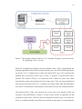
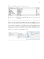
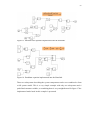
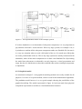
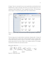
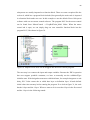
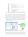
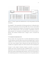
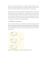
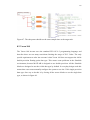
Figure 46. Using multiple time-levels can cause problems in implementation phase.
With multiple time-levels the implementation phase is very important, because we have
to make sure that the time-levels used in the simulation correspond to the time-levels used
in the PLC. In this example if we want the first output signal to pass every second it means
that we have to run the software every 0.2 seconds, because the first output is passed
through every fifth round.
In practice this kind of problems are fortunately quite uncommon. As mentioned earlier
the code generation follows very strictly the original design and these problems can be
easily avoided by selecting the same simulation time for the controller as the target task
is running. In this example the controller’s sample time was on its default value -1 and it
shows just how easy it is to make a mistake with multiple time-levels if we are not careful.
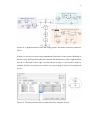
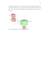
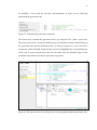
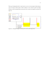
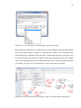
In figure 47 it is shown how the subsystem’s sample time set equal to the task’s cyclic
execution time effects on the generated code. In this case we want to run the software in
10 ms cycles, so the sampling time in the Simulink should be 0.01 seconds.