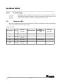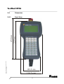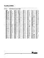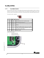
1
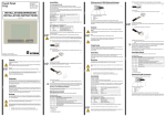
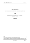
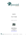
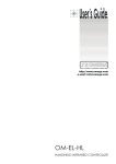
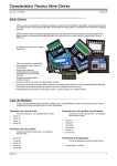
ELECTRONIC GMBH Technical Manual TesiMod Operating Terminal HT06 Version 1.0 issued 8th December 2000 Sütron electronic GmbH Kurze Straße 29 70794 Filderstadt Tel.: 0049 7 11 / 77 09 80 Fax: 0049 7 11 / 77 09 86 0 Email: [email protected] Internet: www.suetron.de TesiMod HT06 V1.0 08.12.2000 First Edition This manual and the illustrations it contains are protected by copyright law. Use of this manual by third parties in a manner that is contrary to copyright terms is prohibited. No part of this document may be reproduced, translated or archived in any form or by means, electronic or photographic, or altered without the express written permission of the Sütron electronic GmbH. Acting in a manner that is contrary to these terms makes the party liable to damages. Sütron electronic reserves the right to make changes that reflect technical advances. 2 TesiMod HT06 /000-0343/ © Copyright by Sütron electronic GmbH HT06_eng_V10.3000000QK0 Table of Contents 1 Explanation of Symbols .................................................. 5 2 The Operating Terminal HT06 ......................................... 5 2.1 Front View .............................................................................. 6 2.2 2.2.1 2.2.2 2.2.3 2.2.4 Keyboard ............................................................................... 7 Editing Keys ................................................................................... 7 Control Keys .................................................................................. 8 Special Keys .................................................................................. 9 Function Keys ............................................................................... 10 2.3 Diagnosis LEDs ...................................................................... 10 2.4 2.4.1 2.4.2 Dimensions ........................................................................... 11 Front View ................................................................................... 11 Side View .................................................................................... 12 2.5 2.5.1 2.5.2 2.5.3 Pin and Connector Assignments ............................................ 13 Open Cable End .......................................................................... 14 12 pin Circular Connector ............................................................. 16 16 pin Circular Connector ............................................................. 18 2.6 Download / Upload Interface ............................................... 20 2.7 Supply Voltage ..................................................................... 20 2.8 Emergency Stop Button ......................................................... 20 2.9 Consent Switch ..................................................................... 21 2.10 2.10.1 2.10.2 2.10.3 2.10.4 2.10.5 2.10.6 Display ................................................................................. 21 Display Contrast Setting ................................................................. 22 Default Contrast Setting ................................................................. 22 Character Attributes ...................................................................... 23 Font Normal ............................................................................ 23 Font Zoom ............................................................................... 23 ASCII Character Set Table ............................................................. 24 2.11 User-Mode Switch ................................................................. 25 2.12 Battery ................................................................................. 26 3 TesiMod HT06 2.13 Fuse...................................................................................... 27 2.14 Application Memory ............................................................. 27 3 Technical Data .............................................................. 28 4 Index ........................................................................... 31 4 TesiMod HT06 1 Explanation of Symbols This manual uses the following symbols to indicate notes and hazardous situations. Notes for the User General Danger Specific Danger 2 The Operating Terminal HT06 The operating terminal HT06 has a display with graphics capabilities and a membrane keyboard with all important functions. A consent switch and an emergency stop button are optional available. The connection to the PLC is possible with prepared cables that are used simultaneously for the power supply. /000-0343/ © Copyright by Sütron electronic GmbH HT06_eng_V10.3000000QK0 The HT06 can be fixed with a magnet (Option) which is attached at the rear side, or with a hook (Option). 5 TesiMod HT06 2.1 Front View 6 TesiMod HT06 1 2 3 4 5 6 7 8 9 10 11 12 13 Enclosure Operating Terminal Type Logo Display Emergency Stop Button (Option) Diagnosis LED Vcc Diagnosis LED RC Diagnosis LED BA Diagnosis LED RD Consent Switch on the Right Side (Option) Status LED Function Keys Function Keys F1 to F8 Status LED Data Release Special Key Data Release 2.2 14 15 16 17 18 19 20 21 22 23 24 25 26 Editing Key Plus Editing Key Minus Special Key Enter Special Key Clear Status LED Help Special Key Help Control Key Page Down Key Cursor Right, Left, Up, Down Special Key Acknowledge Key Cursor Home Editing Key 0 to 9, Alphabet Editing Key Dot Consent Switch on the Left Side (Option) Keyboard The HT06 supports all important key functions in spite of the small measures. The keyboard is built in click touch technology. The stroke distance is approximately 0.4 mm. The active key surface is embossed and has a size of 9 mm. Every key has a symbol area of 13 x 13 mm. The keyboard foil consists of polyester foil. The LEDs that are provided in some of the keys are integrated above into the respective key element. The LED illuminate green. The keyboard has a lifetime of approximately 6 million switching cycles. In standard mode, the function of the keys is as defined by the user. 2.2.1 Editing Keys Key: 0 and ( ) ° is used to edit data within the editor. If the system variable Shift or ShiftCase is programmed, the characters ( and ) and ° can be entered. Key: 1 and STU is used to edit data within the editor. If the system variable Shift or ShiftCase is programmed, the characters S and T and U can be entered. Key: 2 and VWX is used to edit data within the editor. If the system variable Shift or ShiftCase is programmed, the characters V and W and X can be entered. /000-0343/ © Copyright by Sütron electronic GmbH HT06_eng_V10.3000000QK0 Key: 3 and YZ% is used to edit data within the editor. If the system variable Shift or ShiftCase is programmed, the characters Y and Z and % can be entered. Key: 4 and JKL is used to edit data within the editor. If the system variable Shift or ShiftCase is programmed, the characters J and K and L can be entered. Key: 5 and MNO is used to edit data within the editor. If the system variable Shift or ShiftCase is programmed, the characters M and N and O can be entered. 7 TesiMod HT06 Key: 6 and PQR is used to edit data within the editor. If the system variable Shift or ShiftCase is programmed, the characters P and Q and R can be entered. Key: 7 and ABC is used to edit data within the editor. If the system variable Shift or ShiftCase is programmed, the characters A and B and C can be entered. Key: 8 and DEF is used to edit data within the editor. If the system variable Shift or ShiftCase is programmed, the characters D and E and F can be entered. Key: 9 and GHI is used to edit data within the editor. If the system variable Shift or ShiftCase is programmed, the characters G and H and I can be entered. Key: Decimal Point and :?! is used to edit data within the editor. If the system variable Shift or ShiftCase is programmed, the characters : and ? and ! can be entered. Key: Minus and \*/ can be used to enter negative values within the editor. In the increment editor, the variable value is decremented by 1. When the key is held down, the function is repeated at a rate of repetition that is automatically increased. If the system variable Shift or ShiftCase is programmed, the characters \ and * and / can be entered. Key: Plus and <=> can be used to enter positive values within the editor. In the increment editor, the variable value is incremented by 1. When the key is held down, the function is repeated at a rate of repetition that is automatically increased. If the system variable Shift or ShiftCase is programmed, the characters < and = and > can be entered. 2.2.2 Control Keys Key: Cursor left can be programmed to directly select I/O masks. In the editor, it moves the cursor to the left. Key: Cursor right can be programmed to directly select I/O masks. In the editor, it moves the cursor to the right. 8 TesiMod HT06 Key: Cursor up can be programmed to directly select I/O masks. In the editor, it moves the cursor upwards. Key: Cursor down can be programmed to directly select I/O masks. In the editor, it moves the cursor downwards. Key: Cursor home can be programmed to directly select I/O masks. In the editor, it moves the cursor to the position of the first input variable. Key: Page down is used to page through tables, recipes and messages. The functionality corresponds to the system variable TabPgDn. The key allows data contents towards the bottom of the table to be viewed. 2.2.3 Special Keys Key: Help key always displays the current help text (online help). When the statusLED help flashes, it signals that an error message is pending. The error or system message is always displayed in plain-text. Key: Data Release key is used to switch from a menu into the editor. The statusLED data release lights up when the editing mode is active. When the Data Release key is pressed within the editor, the editing mode is exited. Key: Enter is used to conclude data entry. When pressed while in the startup mask, the key switches into the setup mask. /000-0343/ © Copyright by Sütron electronic GmbH HT06_eng_V10.3000000QK0 Key: Clear deletes the character beneath the cursor when it is used in an editor. Deletes the selected messages from the data memory. Key: Acknowledge is used as an acknowledge key for the message system. 9 TesiMod HT06 2.2.4 Function Keys Function key F1 to F8 with integrated LEDs for functional feedback. The key functions can be freely assigned to a softkey functionality, either as direct access keys for menu control or to activate a function in the controller. 2.3 Diagnosis LEDs There are four diagnosis LEDs positioned above the keyboard. The diagnosis LEDs signal different states of the interface and the supply voltage. Diagnosis LEDs Designation Color Function InterBus Function RS232 Function PROFIBUS-DP / MPI Function CAN-Bus Vcc green Voltage Monitor Voltage Monitor Voltage Monitor Voltage Monitor RC green Remote Bus Check - - - BA green Bus Active - Data Exchange - RD red Remote Bus Disabled - - - 10 /000-0343/ © Copyright by Sütron electronic GmbH HT06_eng_V10.3000000QK0 229 mm 253 mm TesiMod HT06 2.4 Dimensions 2.4.1 Front View 85.5 mm 116.5 mm 11 TesiMod HT06 2.4.2 Side View 12 TesiMod HT06 2.5 Pin and Connector Assignments The standard HT06 is delivered with an open cable end. Optionally the terminal can be equipped with the following connectors: 16 pin circular connector 12 pin circular connector /000-0343/ © Copyright by Sütron electronic GmbH HT06_eng_V10.3000000QK0 The interior setup of the cable is always structured in three parts. 1. 3 x 0,5 mm² for supply voltage 2. 2 x 1,0 mm² and 6 x 0,25 mm² for the emergency stop button and the consent switch 3. 5 x 0,25 mm² for communication 13 TesiMod HT06 2.5.1 Open Cable End The standard operating terminal is equipped with an open cable end. Grey shaded entries are only optionally available. Pin Assignment for Open Cable End InterBus Strand Ø mm² PROFIBUS-DP / MPI RS232 CAN-Bus Designation Function Designation Function Designation Function Designation Function RDBU 0,25 NO Consent Switch Left Make Contact NO Consent Switch Left Make Contact NO Consent Switch Left Make Contact NO Consent Switch Left Make Contact PK 0,25 NO Consent Switch Left Make Contact NO Consent Switch Left Make Contact NO Consent Switch Left Make Contact NO Consent Switch Left Make Contact WHGN 0,25 NO Consent Switch Right Make Contact NO Consent Switch Right Make Contact NO Consent Switch Right Make Contact NO Consent Switch Right Make Contact OR 0,25 NO Consent Switch Right Make Contact NO Consent Switch Right Make Contact NO Consent Switch Right Make Contact NO Consent Switch Right Make Contact BU 1,0 NC Emergency Stop Break Contact NC Emergency Stop Break Contact NC Emergency Stop Break Contact NC Emergency Stop Break Contact BN 1,0 NC Emergency Stop Break Contact NC Emergency Stop Break Contact NC Emergency Stop Break Contact NC Emergency Stop Break Contact WHYE 0,25 NC / NO Emergency Stop Break Contact / Make Contact (Optional) NC / NO Emergency Stop Break Contact / Make Contact (Optional) NC / NO Emergency Stop Break Contact / Make Contact (Optional) NC / NO Emergency Stop Break Contact / Make Contact (Optional) BNGN 0,25 NC / NO Emergency Stop Break Contact / Make Contact (Optional) NC / NO Emergency Stop Break Contact / Make Contact (Optional) NC / NO Emergency Stop Break Contact / Make Contact (Optional) NC / NO Emergency Stop Break Contact / Make Contact (Optional) BK 0,5 0V Supply Voltage 0 VDC 0V Supply Voltage 0 VDC 0V Supply Voltage 0 VDC 0V Supply Voltage 0 VDC VT 0,5 + 24V Supply Voltage 24 VDC + 24V Supply Voltage 24 VDC + 24V Supply Voltage 24 VDC + 24V Supply Voltage 24 VDC YE 0,5 GR 0,25 GND Signal Ground DGND Data Transmission Potential GND Signal Ground GND Signal Ground WH 0,25 DI1 Data In CNTRN Control Signal Repeater Minus TD Transmit Data CANH CAN_H Bus Line (Dominant HIGH) BN 0,25 /DI1 Data In Reverse N.C. Not Connected RTS Request to Send CANL CAN_L Bus Line (Dominant LOW) Low-Noise Earth Low-Noise Earth 14 Low-Noise Earth Low-Noise Earth TesiMod HT06 Pin Assignment for Open Cable End RD 0,25 DO1 Data Out RxD/ TxD-N Transmit- / Receive Data Minus /DO1 Data Out Reverse RxD/ TxD-P Transmit- / Receive Data Plus /000-0343/ © Copyright by Sütron electronic GmbH HT06_eng_V10.3000000QK0 GN 0,25 15 CTS RD Clear to Send Receive Data CANL CAN_L Bus Line (Dominant LOW) CANH CAN_H Bus Line (Dominant HIGH) TesiMod HT06 2.5.2 12 pin Circular Connector Optionally the operating terminal can be equipped with a preassembled cable with a 12 pin circular connector. Grey shaded entries are only optionally available. Pin Assignment for 12 pin Circular Connector InterBus Pin Designation Function 1 DI1 Data In 2 /DI1 Data In Reverse 3 GND Signal Ground 4 NC / NO Emergency Stop Break Contact / Make Contact (optional) 5 NC / NO Emergency Stop Break Contact / Make Contact (optional) 6 NC Emergency Stop Break Contact 7 Low-Noise Earth 8 + 24V Supply Voltage 24 VDC 9 DO1 Data Out 10 /DO1 Data Out Reverse 16 TesiMod HT06 Pin Assignment for 12 pin Circular Connector 11 NC Emergency Stop Break Contact 12 0V Supply Voltage 0 VDC /000-0343/ © Copyright by Sütron electronic GmbH HT06_eng_V10.3000000QK0 The external shield and the bus shield must be connected to the metal hoods of the connector housing over as large a surface as possible. 17 TesiMod HT06 2.5.3 16 pin Circular Connector Optionally the operating terminal can be equipped with a preassembled cable with a 16 pin circular connector. Grey shaded entries are only optionally available. Pin Assignment for 16 pin Circular Connector InterBus Pin PROFIBUS-DP / MPI RS232 CAN-Bus Designation Function Designation Function Designation Function Designation Function 1 NO Consent Switch Left Make Contact NO Consent Switch Left Make Contact NO Consent Switch Left Make Contact NO Consent Switch Left Make Contact 2 NO Consent Switch Right Make Contact NO Consent Switch Right Make Contact NO Consent Switch Right Make Contact NO Consent Switch Right Make Contact 3 NC Emergency Stop Break Contact NC Emergency Stop Break Contact NC Emergency Stop Break Contact NC Emergency Stop Break Contact 4 NC Emergency Stop Break Contact NC Emergency Stop Break Contact NC Emergency Stop Break Contact NC Emergency Stop Break Contact 5 NC / NO Emergency Stop Break Contact / Make Contact (Optional) NC / NO Emergency Stop Break Contact / Make Contact (Optional) NC / NO Emergency Stop Break Contact / Make Contact (Optional) NC / NO Emergency Stop Break Contact / Make Contact (Optional) 6 NC / NO Emergency Stop Break Contact / Make Contact (Optional) NC / NO Emergency Stop Break Contact / Make Contact (Optional) NC / NO Emergency Stop Break Contact / Make Contact (Optional) NC / NO Emergency Stop Break Contact / Make Contact (Optional) 7 GND Signal Ground DGND Data Transmission Potential GND Signal Ground GND Signal Ground 8 0V Supply Voltage 0 VDC 0V Supply Voltage 0 VDC 0V Supply Voltage 0 VDC 0V Supply Voltage 0 VDC 18 TesiMod HT06 Pin Assignment for 16 pin Circular Connector 9 + 24V 10 Supply Voltage 24 VDC + 24V Low-Noise Earth Supply Voltage 24 VDC + 24V Low-Noise Earth Supply Voltage 24 VDC + 24V Low-Noise Earth Supply Voltage 24 VDC Low-Noise Earth 11 NO Consent Switch Left Make Contact NO Consent Switch Left Make Contact NO Consent Switch Left Make Contact NO Consent Switch Left Make Contact 12 NO Consent Switch Right Make Contact NO Consent Switch Right Make Contact NO Consent Switch Right Make Contact NO Consent Switch Right Make Contact Control Signal Repeater Minus TD Transmit Data CANH CAN_H Bus Line (Dominant HIGH) 13 DI1 Data In CNTRN 14 /DI1 Data In Reverse N.C. Not Connected RTS Request to Send CANL CAN_L Bus Line (Dominant LOW) 15 DO1 Data Out RxD/ TxD-N Transmit- / Receive Data Minus CTS Clear to Send CANL CAN_L Bus Line (Dominant LOW) 16 /DO1 Data Out Reverse RxD/ TxD-P Transmit- / Receive Data Plus RD Receive Data CANH CAN_H Bus Line (Dominant HIGH) /000-0343/ © Copyright by Sütron electronic GmbH HT06_eng_V10.3000000QK0 The external shield and the bus shield must be connected to the metal hoods of the connector housing over as large a surface as possible. 19 TesiMod HT06 2.6 Download / Upload Interface The interface X3 (SER2-RS232c) is responsible for the upload or the download. The following steps must be done for this purpose: - 1 2.7 Remove the fastening screws of the enclosure at the rear side and remove the enclosure Plug the ribbon cable adaptor on the interface X3 (see figure below) Connect the ribbon cable adaptor with the download cable Connect the download cable with an available interface of your computer Now you can carry out the upload or download Remove the download cable and the ribbon cable adaptor after the upload/download Place the enclosure on the rear side of the unit Fasten the screws of the enclosure properly Position of the interface X3 (SER2-RS232c) Supply Voltage The unit is equipped with a reverse voltage protection. If the poling is wrong, the unit doesnt operate. This unit confirms to the safety class I. For safe operation it is necessary to use safety extra-low voltage (SELV) in accordance with DIN EN 61131 for the supply voltage. 2.8 Emergency Stop Button The operating terminal is optionally equipped with an emergency stop button at the end face. The button has a mechanical lifetime of approximately 30000 switching cycles. The switch elements in the button have a lifetime of approximately 5 million switching cycles. Two break contacts or optionally one break contact and one make contact are actuated. 20 TesiMod HT06 2.9 Consent Switch The operating terminal is optionally equipped with a consent switch on the left and the right hand side. Each switch has a mechanical lifetime of approximately 1 million switching cycles. The switch element has a lifetime of approximately 500 000 switching cycles. One make contact is actuated per consent 2.10 Display The Display for the HT06 at a glance: Type: Resolution: Graphics Capabilities: Backlight: Viewing Angle: Default Contrast Setting: Contrast Setting: Lifetime LCD: Lifetime Backlight: Display potentiality: Displayable Character Attributes: LCD Module 126 x 64 Pixel Full Graphics LED 90 ° By User-Mode Switch By Software, Temperature Compensated 100.000 h 100.000 h Extended ASCII Character Set, Full Graphics Inverse, Flashing, Zoom and Underlined Lines (Font Normal): Characters/Line (Font Normal): Character Matrix (Font Normal): Character Height (Font Normal): Character Matrix (Font Zoom): Character Height (Font Zoom): Pixel Colour: Background Colour: Pixel Size: 8 21 6 x 8 Pixel 4,1 mm 12 x 16 Pixel 8,3 mm Black Yellow-Green 0,48 x 0,48 mm Visible Front Cutout: 40 mm x 72 mm (H x W) /000-0343/ © Copyright by Sütron electronic GmbH HT06_eng_V10.3000000QK0 If the display is damaged, do not swallow or breathe in the liquids or gases being emitted and avoid direct contact with skin. Danger of Poisoning! Could Result in Burns! 21 TesiMod HT06 2.10.1 Display Contrast Setting The contrast for the display can be adjusted by means of the software. This requires the system variable LCDContrast to be set up in an I/O mask of the application. The value can then be modified using any editor that can handle integer numbers. The limit values for the brightness must be set to Lower level: Upper level: -25 +125 If this variable is not defined, the default setting (value 25) will be loaded when the system is initialized. The system variable can be stated in any I/O-mask of the application! 2.10.2 Default Contrast Setting If the contrast of the display should be such that the masks are no longer legible, the default contrast setting can be restored using the user-mode switch. Position of the switch to restore the contrast: S1 S2 S3 S4 ON OFF OFF ON This switch position coincides with activating download by hardware. The contrast will be reset before the warning is displayed. The warning will be displayed in a legible manner. How to setup the default contrast: - Switch off the operating terminal - Remove the fastening screws of the enclosure at the rear side and remove the enclosure - Set the DIP-switches to the above described switch positions - Switch on the operating terminal - Upon display of a warning, switch off the operating terminal - Set the switch S4 to the OFF-position - Place the enclosure on the rear side of the unit - Fasten the screws of the enclosure properly - Switch on the terminal again. The application description is not lost. 22 TesiMod HT06 2.10.3 Character Attributes By preselecting an attribute, any characters can be displayed as follows: - normal - flashing - underlined - inverse and in any combination. Font Normal 2.10.5 Font Zoom /000-0343/ © Copyright by Sütron electronic GmbH HT06_eng_V10.3000000QK0 2.10.4 23 TesiMod HT06 2.10.6 ASCII Character Set Table 24 TesiMod HT06 2.11 User-Mode Switch The user-mode switch is below on the right of the keyboard card of the terminal. In order to be able to actuate the user-mode switch, the enclosure must be open. Remove the fastening screws of the enclosure at the rear side and remove the enclosure. The keyboard card is in the top part of the enclosure. User-mode switch 4 Switches S1 S2 S3 S4 Function I X - - Standard-Mode with PLC (delivery state) I X I - Standard-Mode without PLC - I - - Transparent-Mode with start and stop code of the keys - - - I Transparent-Mode without stop code of the keys I - - I Activate download (deletes application memory) und default contrast setting I - I I Activate upload /000-0343/ © Copyright by Sütron electronic GmbH HT06_eng_V10.3000000QK0 Legend of above table: I = Switch position ON = Switch position OFF X = Switch position arbitrary 1 Position of the user-mode switch 25 TesiMod HT06 2.12 Battery A built-in lithium battery buffers the data in the CMOS-RAM memory and also supplies the real-time clock with power. The battery provides a lifetime of at least 5 years, even under unfavourable operating conditions. If the battery is drained the system message change battery is generated. We recommend to change the battery at maintenance in a interval of 4 years. A new battery is supported by Sütron electronic or the sales representative of your country. When the message change battery is recognized too late, for example real-time clock stopped or displays wrong date, it is possible that the data in the CMOS-RAM is lost. Therefore you have to check the data (changeable passwords, parameters in the system variables, data set of the recipes and the entries in the message system). Replacing the battery: The battery can be replaced while the operating voltage is connected to ensure that the message data and time setting are not lost. Mind the safety instructions! - Remove the fastening screws of the enclosure at the rear side and remove the enclosure - Replace the cable fastener, which is used to hold the battery - Plug off the connector of the battery cable and replace the battery - Plug on the connector of the new battery - Place the new battery onto the plastic carrier on the printed circuit board and fasten it with a new cable fastener - Place the enclosure on the rear side of the unit - Fasten the screws of the enclosure properly Changing the battery may only be performed by qualified and authorized personnel! Sewage and refuse disposal: Dispose only drained batteries into the collection box of the community or of the local dealer. The battery is stated as drained when the message change battery appears on the display of the appliance. To prevent short circuitry in the collection boxes insulate the poles of each battery with insulation tape or put each single battery into a plastic bag. Do not put lithium batteries in fire or heat them above 100° C and do not recharge them. Danger of Explosion! Do not open lithium batteries. Danger of Poisoning! Hazardous voltages can exist inside electrical installations that can pose a danger to humans. Coming in contact with live parts may result in electric shock! Electrostatic discharges can damage electronic components! ESD protective measures must be observed! 26 TesiMod HT06 2.13 Fuse A semiconductor fuse is used to prevent damage to the operating terminal. Once the fuse has been activated, the device must be disconnected from the supply voltage to allow the semiconductor fuse to regenerate. With an ambient temperature of 20 °C, the regeneration takes about 20 seconds. The higher the ambient temperature, the longer the regeneration period. The semiconductor fuse is not designed to be replaced. 2.14 Application Memory /000-0343/ © Copyright by Sütron electronic GmbH HT06_eng_V10.3000000QK0 The unit is equipped with a 256 KByte flash memory as application memory. After switching on the unit the size of the application memory is displayed. This memory area is available to store the user application, the loadable protocol driver, the fonts and the recipe data. 27 TesiMod HT06 3 Technical Data Keyboard A Total of 32 Keys, ClickTouch PCB Keyboard, 6 Million Switching Cycles Divided into 6 Control Keys 2 Special Keys with LED 3 Special Keys without LED 13 Editing Keys 8 Function Keys Display Type: Resolution: Backlight: Display Area: Pixel Size: Pixel Distance: Lifetime LCD: Lifetime Backlight: Interfaces Variable Baud Rates and Data Formats Internal X3 SER2 RS232c, Not Galvanical Isolated Download/Upload InterBus, not Galvanical Isolated Communication PROFIBUS-DP, Galvanical Isolated Communication MPI, Galvanical Isolated Communication CAN-Bus, Galvanical Isolated Communication RS232, Galvanical Isolated Communication (InterBus, PROFIBUS-DP and MPI are Terminated in the Terminal.) Protocolls Standard LCD Module 126 x 64 Pixel LED 40 x 72 mm (H x W) 0.48 x 0.48 mm 0.04 mm 100000 h 100000 h ABB CS31 ABB T200 AEG KS-Functions AEG Modbus Allen Bradley* Bosch BUEP19/BUEP19E* DIN-Meßbus Slave, DIN-Meßbus Gateway* GE Fanuc SNP* IDEC Micro3* Jetter PASE / PCOM5* Klaschka YCOM/C* Moeller SUCOM 1 (PS306/316)* Moeller SUCOM 1 (PS4-201) Mitsubishi FX-Series and A-Series* OMRON Host-Link OMRON NT-Link Siemens Sinec L1 Master Link* Siemens 3964R/RK512* 28 TesiMod HT06 Siemens S5 PG (AS511)* Siemens S7 PPI* * This interfacing is possible for some controller types only with interface converter. /000-0343/ © Copyright by Sütron electronic GmbH HT06_eng_V10.3000000QK0 Protocolls Field Bus CAN/CANopen InterBus PROFIBUS-DP Siemens S7 MPI Central Unit Z84-CPU, 10 MHz, Watchdog Timer, Real-Time Clock, Programmable Interface Parameters, Temperature Compensation of the Display, Adjustment of Contrast, Battery Monitoring, User-Mode Switch Memory 256 KByte Flash Memory, Application Memory 256 KByte Flash Memory, Firmware 128 KByte stat. CMOS-RAM, Battery Backed Connection System 12 pin Circular Connector 16 pin Circular Connector Connection Cable Diameter: Weight: Bending for Fixed Installation: Bending for Loose Installation: Supply Voltage 24 V Direct Voltage, Residual Ripple Max. 10%, SELV in Accordance to DIN EN 61131 Minimum Voltage 19,2 V Maximum Voltage 30,2 V Typ. Power Consumption <0,25 A Peak Current <0,5 A Connected Load ~5 W Fuse Semiconductor Fuse Reverse Voltage Protection Protection Diode Emergency Stop Button (Option) Type: Lifetime: Switch Unit: 11 mm approx. 172 g/m 4 x Diameter of Cable 10 x Diameter of Cable Rafi RAFIX 16 1.30074.122 3 x 10⁴ Switching Cycles Rafi RAFIX 16 Universal Switch Unit 2 NC or Optionally 1 NC + 1 NO 5 x 10⁵ Switching Cycles Lifetime: 29 TesiMod HT06 Consent Switch (Option) Typ: Lifetime: Switch Unit: Lifetime: ITW Switch Series 59 1 x 10⁵ Switching Cycles 1 NO 5 x 10⁴ Switching Cycles Noise Immunity EC Electromagnetic Compatibility Directive 89/336/EEC EN 50082-2 EN 55011 Limit Class B EN 55022 EN 61000-4-2 EN 61000-4-3 EN 61000-4-4 EN 61000-4-5 EN 61000-4-6 Environmental Test Operating Temperature Storage Temperature Relative Humidity for: Operation Storage Non-condensing 0°C to +50°C -10°C bis +70°C Max. 75% Annual Average Max. 75% Annual Average Degrees of Protection EN 60529 Mechanical Degrees of Protection Impermeability IP54 Enclosure Type: Material: Colour: Impact Resistance: Burning Behaviour: Measures Without Emergency Stop Button: Approx. 229 x 116.5 x 125 (L x W x D) With Emergency Stop Button: Approx. 253 x 116.5 x 125 (L x W x D) Weight 415 g Without Cable (Weight of Cable Approx. 172 g/m) 30 ROSE Beluga 2200 Polyamide RAL7021 >7 Nm in Accordance to DIN 50014 V2 in Accordance to UL94 TesiMod HT06 4 Index A F1 to F16 10 Help 9 Minus 8 Page up 9 Plus 8 Keyboard 7 Application Memory 27 ASCII Zeichensatz 24 B Battery 26 P C Pin Assignment 12 pin Circular Connector 16 16 pin Circular Connector 18 Open Cable End 14 Character Attributes 23 Consent Switch 21 Contast Setting 22 Control Keys 8 S D Special Keys 9 Supply Voltage 20 Default Contrast Setting 22 Diagnosis LEDs 10 Dimensions Front View 11 Side View 12 Display 21 Download Interface 20 T Technical Data 28 U User-Mode Switch 25 E Editing Keys 7 Emergency Stop Button 20 Explanation of Symbols 5 F Font Normal 23 Zoom 23 Front View 6 Function Keys 10 Fuse 27 /000-0343/ © Copyright by Sütron electronic GmbH HT06_eng_V10.3000000QK0 K Key Acknowledge 9 Clear 9 Cursor down 9 Cursor home 9 Cursor left 8 Cursor right 8 Cursor up 9 Data Release 9 Decimal Point 8 Enter 9 31