1
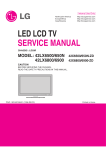
Artisan Technology Group is your source for quality
new and certified-used/pre-owned equipment
• FAST SHIPPING AND
DELIVERY
• TENS OF THOUSANDS OF
IN-STOCK ITEMS
• EQUIPMENT DEMOS
• HUNDREDS OF
MANUFACTURERS
SUPPORTED
• LEASING/MONTHLY
RENTALS
• ITAR CERTIFIED
SECURE ASSET SOLUTIONS
SERVICE CENTER REPAIRS
Experienced engineers and technicians on staff
at our full-service, in-house repair center
WE BUY USED EQUIPMENT
Sell your excess, underutilized, and idle used equipment
We also offer credit for buy-backs and trade-ins
www.artisantg.com/WeBuyEquipment
InstraView REMOTE INSPECTION
LOOKING FOR MORE INFORMATION?
Visit us on the web at www.artisantg.com for more
information on price quotations, drivers, technical
specifications, manuals, and documentation
SM
Remotely inspect equipment before purchasing with
our interactive website at www.instraview.com
Contact us: (888) 88-SOURCE | [email protected] | www.artisantg.com
User’s Guide
VMFC-2100/2230/2250
Fibre Channel I/O Module
Rev. 1.3 - Valid for VMFC-2100 & VMFC-2230/50 PMC & PCI versions
VMFC-2100/22x0 USER’S MANUAL
Artisan Technology Group - Quality Instrumentation ... Guaranteed | (888) 88-SOURCE | www.artisantg.com
The information in this document is subject to change without notice and should not be construed as a
commitment by VMETRO. While reasonable precautions have been taken, VMETRO assumes no
responsibility for any errors that may appear in this document.
© Copyright VMETRO 2001.
This document may not be furnished or disclosed to any third party and may
not be copied or reproduced in any form, electronic, mechanical, or
otherwise, in whole or in part, without prior written consent of VMETRO
Inc. (Houston, TX, USA) or VMETRO ASA (Oslo, Norway).
VMFC-2100/22x0 USER’S MANUAL
Artisan Technology Group - Quality Instrumentation ... Guaranteed | (888) 88-SOURCE | www.artisantg.com
Warranty
VMETRO products are warranted against defective materials and workmanship within the warranty period of 1
(one) year from date of invoice. Within the warranty period, VMETRO will, free of charge, repair or replace any
defective unit covered by this warranty, shipping prepaid. A Return Authorization Code should be obtained
from VMETRO prior to return of any defective product. With any returned product, a written description of the
nature of malfunction should be enclosed. The product must be shipped in its original shipping container or
similar packaging with sufficient mechanical and electrical protection in order to maintain warranty.
This warranty assumes normal use. Products subjected to unreasonably rough handling, negligence,
abnormal voltages, abrasion, unauthorized parts replacement and repairs, or theft are not covered by this
warranty and will if possible be repaired for time and material charges in effect at the time of repair. Any
customer modification to VMETRO products, including conformal coating, voids the warranty unless agreed to
in writing by VMETRO.
If boards that have been modified are returned for repair, this modification should be removed prior to the
board being shipped back to VMETRO for the best possibility of repair. Boards received without the
modification removed will be reviewed for repairability. If it is determined that the board is not repairable, the
board will returned to the customer. All review and repair time will be billed to the customer at the current time
and materials rates for repair actions.
VMETRO's warranty is limited to the repair or replacement policy described above and neither VMETRO nor
its agent shall be responsible for consequential or special damages related to the use of their products.
Limited Liability
VMETRO does not assume any liability arising out of the application or use of any product described herein;
neither does it convey any license under its patent rights nor the rights of others. VMETRO products are not
designed, intended, or authorized for use as components in systems intended to support or sustain life, or for
any application in which failure of the VMETRO product could create a situation where personal injury or
death may occur. Should Buyer purchase or use VMETRO products for any such unintended or unauthorized
application, Buyer shall indemnify and hold VMETRO and its officers, employees, subsidiaries, affiliates, and
distributors harmless against all claims, costs, damages, and expenses, and reasonable attorney fees arising
out of, directly or indirectly, any claim of personal injury or death associated with such unintended or
unauthorized use, even if such claim alleges that VMETRO was negligent regarding the design or
manufacture of the part.
USA:
VMETRO, Inc.
1880 Dairy Ashford, Suite 535
Houston, TX 77077, USA
Tel.: (281) 584-0728
Fax: (281) 584-9034
Email: [email protected]
Europe, Asia:
VMETRO asa
Brynsveien 5
N-0667 OSLO, Norway
Tel.: +47 2210 6090
Fax: +47 2210 6202
Email: [email protected]
http://www.vmetro.com/
VMFC-2100/22x0 USER’S MANUAL
Artisan Technology Group - Quality Instrumentation ... Guaranteed | (888) 88-SOURCE | www.artisantg.com
This page is left deliberately blank.
VMFC-2100/22x0 USER’S MANUAL
Artisan Technology Group - Quality Instrumentation ... Guaranteed | (888) 88-SOURCE | www.artisantg.com
Contents
General Information
6
This document ...........................................................................................................................6
Conventions used in this document .............................................................................6
Related Documents .....................................................................................................7
Product Overview
8
VMFC-2100/22x0 .....................................................................................................................8
Block Diagram ..........................................................................................................................8
Key features VMFC-2100, VMFC-2230 and VMFC-2250 ........................................9
Protocol Engine...........................................................................................................9
OmniPort integrated hub Interconnection ...................................................................9
PCI interface .............................................................................................................12
Installation
13
Board Precautions ...................................................................................................................13
Unpacking ...............................................................................................................................13
Installation of PMC VMFC-2100/22x0 Module .....................................................................13
Assembly Procedure................................................................................................................14
Configuration Switch & Jumpers ............................................................................................15
Front Panel Indicators
16
Fibre Channel cable connection
16
Front Panels
18
Board Layouts .........................................................................................................................19
VMFC-2100/22x0 Specifications
21
Appendix I: Laser Safety
23
Laser Safety Information and laser specifications.....................................................23
Appendix II: Fibre Channel cables available from VMETRO
25
Appendix III: Copper connector information
27
Appendix IV: ISP2100A Data Sheet
29
Appendix V: ISP2200 Data Sheet
31
Appendix VI:
33
List of Tables...........................................................................................................................33
List of Figures .........................................................................................................................33
VMFC-2100/2250 USER'S MANUAL
General Information • 5
Artisan Technology Group - Quality Instrumentation ... Guaranteed | (888) 88-SOURCE | www.artisantg.com
General Information
This document
This document has been prepared to help the customer get started with the VMFC2100 or VMFC-22x0 Fibre Channel module. The following models are covered by
this document:
VMFC-2100/22x0-DC:
Fibre Channel PMC module with a dual copper
HSSDC interface and integrated hub.
VMFC-2100/22x0-CF:
Fibre Channel PMC module with single fiberoptic and single HSSDC copper interface and
integrated hub.
VMFC-2100/22x0-DF:
Fibre Channel PMC module with dual fiber-optic
interface and integrated hub.
.
VMFC-2100P/22x0P-xx:
Fibre Channel PCI module for PC installation.
Conventions used in this document
The following section describes conventions used in this document.
Symbols
Meaning:
The STOP symbol indicates a section of critical importance. Overlooking this
information may cause damage to the VMFC-xx00 and/or other equipment.
Indicates important, but not crucial, information. Still, you should take notice if
you want to use all capabilities built into your VMFC-xx00.
VMFC-2100/2250 USER'S MANUAL
General Information • 6
Artisan Technology Group - Quality Instrumentation ... Guaranteed | (888) 88-SOURCE | www.artisantg.com
Related Documents
This document does not include detailed information about the following:
•
Fibre Channel Standard
•
PCI Local Bus Specification V2.2
Since this document is only written as a guide to the installation and operation of the
VMFC-xx00, there are only small references to the above specifications. If more
information is required, refer to the following:
Producer
Document
VMETRO
- FC-AL SCSI Driver Reference Guide
Contact VMETRO for more information
PCI Special Interest Group
- PCI Local Bus Specification Revision 2.2
Available from http://www.pcisig.com/
Fibre Channel Association
- Information on Fibre Channel standards
- FC information book: Connection to the Future
Available from http://www.fibrechannel.com
VMFC-2100/2250 USER'S MANUAL
General Information • 7
Artisan Technology Group - Quality Instrumentation ... Guaranteed | (888) 88-SOURCE | www.artisantg.com
Product Overview
VMFC-2100/22x0
The VMFC-2100/22x0 is a Fibre Channel PMC module specifically designed to
maximize throughput while minimizing transfer latency and host processor
overhead in embedded real-time applications. In addition to mainstream Fibre
Channel applications such as disk storage, this interface is particularly well suited to
applications where low latency communications and high-sustained throughput are
essential. This includes areas such as multi-processor communications (telecom &
radar signal processor), sensor I/O (radar, sonar & image processing), and ultra-high
performance computer networks (digital broadcasting & subsystems data links).
Block Diagram
External Ports
TX FIFO
PCI Interface
32/64 Bit
2 Channel DMA
RX FIFO
FC0 and FC1
Gbit
Transceiver
and Data
Codec
3 Port
“Intergrated Hub”
Auto & S/W Bypass
Copper or Optical
33MHz (VMFC-2100)
4 Channel DMA
66MHz (VMFC-22x0)
FC2 and FC4 Protocol Engine
(HW,RISC Processor & Firmware)
PCI Bus
Host
Memory
Host
Processor
Figure 1: VMFC-2100/22x0 Block Diagram
VMFC-2100/2250 USER'S MANUAL
Product Overview • 8
Artisan Technology Group - Quality Instrumentation ... Guaranteed | (888) 88-SOURCE | www.artisantg.com
Key features VMFC-2100, VMFC-2230 and VMFC-2250
VMFC-2230, VMFC-2250
VMFC-2100
QLOGIC ISP-2200 RISC Processor
QLOGIC ISP-2100 RISC Processor
200 MB/s Full duplex (2 x 100 MB/s)
100 MB/s Half duplex (1 x 100 MB/s)
64bit 66Mhz PCI
64bit 33MHZ PCI
Improved Remote DMA
Latency reduced by 30 to 50%
Broadcast (2250 only)
Public loop and direct fabric logon
VMFC-2100 direct replacement
External receive FIFO (2250 only)
Protocol Engine
The Protocol Engine incorporated into the VMFC-2100/22x0 consists of the QLogic
ISP-2x00 with associated application firmware. The QLogic ISP-2x00 is the highest
performance single chip Fibre Channel controller, making use of an integrated RISC
processor to reduce host processor utilization by offloading the Fibre Channel
protocol processing. The firmware is downloaded by the host processor at start-up,
and can be changed to provide field upgrades and to support field upgrades.
OmniPort integrated hub Interconnection
The integrated hub capabilities of the Patent pending OmniPort Fibre Channel I/O
port allows for simple cascading of multiple Fibre Channel devices. Standard duplex
HSSDC copper and SC Duplex fiber optic cabling is supported. Three modes of
operation include integrated hub, redundant point to point and redundant arbitrated
loop (JBOD connection).
Figure 2: Intergrated Hub block diagram
VMFC-2100/2250 USER'S MANUAL
Product Overview • 9
Artisan Technology Group - Quality Instrumentation ... Guaranteed | (888) 88-SOURCE | www.artisantg.com
Mode 1: Integrated Hub
The OmniPort automatically extends the loop as more devices are added. It does not
matter which of the two ports are used.
OmniPort
OmniPort
OmniPort
OmniPort
P1
P2
P3
P4
Figure 3: Integrated Hub functional
diagram
Figure 4: Integrated Hub connection.
Interprocessor and Shared Disk - Automatic Hub
The OmniPort automatically extends the loop as more devices are added. It does not
matter which of the two ports are used.
DiskArray
OmniPort
OmniPort
OmniPort
P1
P2
P3
Figure 6: Integrated Hub functional
diagram
Figure 5: Automatic Hub
connection
VMFC-2100/2250 USER'S MANUAL
Product Overview • 10
Artisan Technology Group - Quality Instrumentation ... Guaranteed | (888) 88-SOURCE | www.artisantg.com
Single Failure Redundant Hub
This mode significantly increases the reliability of the loop. Any single failure will
still allow the loop to operate normally. The ports must be connected from port 1 to
port 2 of the next device as shown in Fig. 4.
OmniPort
OmniPort
OmniPort
OmniPort
P1
P2
P3
P4
Processor 4
Processor 3
Processor 2
Processor 1
Figure 8: Redundant Hub
Functional diagram
Figure 7: Redundant Hub
Mode 2: Redundant Point to Point Connection
The OmniPort supports a redundant channel mode where two host adapters can be
redundantly connected. The OmniPort always stays on port 1 unless the loop on port
1 has failed, in which case it will switch to port 2. It will switch back to port 1 as
soon as the loop on port 1 is operational. The redundant (standby loop) is looped
back to the disk array. TX data is present on both ports.
OmniPort
OmniPort
P1
P2
Figure 10: Redundant point to point
functional diagram
Figure 9: Redundant point to point
connection
VMFC-2100/2250 USER'S MANUAL
Product Overview • 11
Artisan Technology Group - Quality Instrumentation ... Guaranteed | (888) 88-SOURCE | www.artisantg.com
Mode 3:Redundant Arbitrated Loop (JBOD connection)
When connected to a redundant Disk array, the OmniPort automatically switches to
the redundant loop when the current loop fails. The redundant (standby loop) is
looped back to the disk array. The OmniPort will park on the last known good loop
and only switch upon failure detection.
DiskArray
OmniPort
P1
Figure 11: Redundant Arbitrated Loop
functional diagram
Figure 12: Redundant Arbitrated Loop connection
PCI interface
The VMFC-2100/22x0 is designed to interface directly to a PCI local bus and operate as a 32 or 64bit DMA master, which is backward compatible to 32-bit operation. The PCI host bus interface is
compliant with PCI Local Bus Specification revision 2.1. Further information can be found in the PCI
Local Bus Specification Rev 2.2 and in Appendix IV: ISP2100A Data Sheet or Appendix V: ISP2200
Data Sheet .
VMFC-2100/2250 USER'S MANUAL
Product Overview • 12
Artisan Technology Group - Quality Instrumentation ... Guaranteed | (888) 88-SOURCE | www.artisantg.com
Installation
Board Precautions
- The VMFC-2100/22x0 circuit board is sensitive to static electricity and can be
damaged by a static discharge. Always wear a grounded anti-static wrist strap and
use grounded, static protected work surfaces when touching the circuit board and
its components.
- When the board is not installed, always keep in the static-protective envelope.
Unpacking
All precautions described above must be taken when unpacking the VMFC-2100
/22x0 from its shipping container. Verify that no damage has occurred in the
shipment. Refer to packing list and verify that all items are present.
Installation of PMC VMFC-2100/22x0 Module
This procedure explains how to mount the VMFC-2100/22x0 on to a VMETRO
PowerMIDAS (not ruggedized version). Although mounting is to a MIDAS card,
the procedure is quite generic and could be helpful when mounting to other PMC
carriers.
Note:
- Be extremely careful when inserting screws to secure PMC modules. Touching
component leads or the printed circuit board itself, with a screwdriver may cause
permanent damage to the board.
- Do not install the VMFC-2100/22x0 while power is applied
VMFC-2100/2250 USER'S MANUAL
Installation • 13
Artisan Technology Group - Quality Instrumentation ... Guaranteed | (888) 88-SOURCE | www.artisantg.com
Assembly Procedure
PMC version
The MIDAS and other PMC carrier boards are usually shipped with two PMC
filler panels mounted in the front panel. They act as EMC shielding in unused
PMC positions. Before installing a PMC module, the filler panel(s) must be
removed. This is done by pushing them out from the backside of the front panel.
Four screws must be used to secure each PMC on the PMC carrier board.
The VMFC-2100/22x0 comes with two pre-installed 10 x 2.5mm spacers for
mounting onto the PMC carrier PCB. If they have been removed, replace them
before continuing the installation.
STEP#1:
Mount VMFC-2100/22x0 module(s) on the PMC carrier board.
See Figure 13
- Place the PMC carrier board on a smooth static protected work surface.
- Install VMFC-2100/22x0 module #1 in a vacant position on the PMC carrier
board by first aligning the front-panel into the PMC carrier front-panel slot and
then firmly seating the back of the VMFC-2100/22x0 into the PMC carrier
connectors.
- Install VMFC-2100/22x0 module #2 in the other vacant PMC carrier position as
described above (if required)
- Double check to ensure that all PMC connectors is well mated.
VMFC-2100/22x0 Module #1
VMFC-2100/22x0 Module #2
Figure 13: Steps 1: Mount VMFC-2100/22x0 module(s) on the PowerMIDAS PMC carrier board.
VMFC-2100/2250 USER'S MANUAL
Installation • 14
Artisan Technology Group - Quality Instrumentation ... Guaranteed | (888) 88-SOURCE | www.artisantg.com
STEP#2:
Mount and fasten screws to the back of the PMC carrier board.
- Secure PMC modules with screws on the bottom side of the PMC carrier board.
- The VMFC-2100/22x0 is now ready for operation.
PCI version
The PCI version of the VMFC-2100/22x0 requires a standard personal computer
PCI slot. For Windows NT driver installation instructions, refer to other
documentation accompanying this product.
Configuration Switch & Jumpers
There are no user adjustable switches or jumpers on the VMFC-2100/22x0.
VMFC-2100/2250 USER'S MANUAL
Installation • 15
Artisan Technology Group - Quality Instrumentation ... Guaranteed | (888) 88-SOURCE | www.artisantg.com
Front Panel Indicators
There are four LED indicators on the front panel of the Host Adapter assigned as
follows:
AUT
– The OmniPort is configured for automatic operation. (Default)
LCL
– The Host Adapter Fibre Channel controller is active.
P1
– Valid Fibre Channel signaling is detected on external port 1.
P2
– Valid Fibre Channel signaling is detected on external port 2.
Fibre Channel cable connection
VMFC-2100-DF
The simplest connection possible with the VMFC-2100/22x0 is the point to point
connection. For this type of connection 2, VMFC-2100/22x0's can be connected or
a VMFC-2100/22x0 can be used in conjunction with another Fibre channel device
to form a point to point communications link.
Molex recommends that the minimum Fibre Channel optical-fiber cable length is
2 meters. Cable lengths shorter than this can saturate the optical receiver under
some circumstances.
VMETRO
VMFC-2100-DF
VMETRO
VMFC-2100-DF
Processor 1
Processor 2
Single point to point connection.
Figure 14: Single point to point connection
VMFC-2100/2250 USER'S MANUAL
Front Panel Indicators • 16
Artisan Technology Group - Quality Instrumentation ... Guaranteed | (888) 88-SOURCE | www.artisantg.com
Multi node loop connection
When using VMFC-2100/22x0-DF in a loop topology, the standard dual Fibre
channel cable must have its connectors separated in-order to allow connection
between the nodes. As most Fibre Channel optical-cables come as a
receiver/transmitter pair, the separation must be done manually. The procedure for
separation of the dual “SC” connector varies from manufacture to manufacture and
is therefore not covered in detail in this manual.
VMETRO
VMFC-2100-DF
VMETRO
VMFC-2100-DF
Processor 2
Processor 3
VMETRO
VMFC-2100-DF
Processor 4
VMETRO
VMFC-2100-DF
Processor 1
Figure 15: Separating Fibre Channel SC cables from retainer
Figure 16: Multi node loop connection using the VMFC-2100-F
VMFC-2100/2250 USER'S MANUAL
Fibre Channel cable connection • 17
Artisan Technology Group - Quality Instrumentation ... Guaranteed | (888) 88-SOURCE | www.artisantg.com
Front Panels
P1
LCL
P1
LCL
P1
LCL
P2
AUT
P2
AUT
P2
AUT
VMFC-2100
DC
Figure 17: PMC & PCI
Dual Copper
VMFC-2100/2250 USER'S MANUAL
VMFC-2100
CF
Figure 18: PMC & PCI
Combo
VMFC-2100
DF
Figure 19: PMC & PCI
Dual Fiber
Front Panels • 18
Artisan Technology Group - Quality Instrumentation ... Guaranteed | (888) 88-SOURCE | www.artisantg.com
Board Layouts
Figure 20: VMFC-2100 PMC Board layout
Figure 21: VMFC-2100 PCI Board layout
VMFC-2100/2250 USER'S MANUAL
Front Panels • 19
Artisan Technology Group - Quality Instrumentation ... Guaranteed | (888) 88-SOURCE | www.artisantg.com
Figure 22: VMFC-2250 PMC Board layout
VMFC-2100/2250 USER'S MANUAL
Front Panels • 20
Artisan Technology Group - Quality Instrumentation ... Guaranteed | (888) 88-SOURCE | www.artisantg.com
VMFC-2100/22x0 Specifications
Fibre Channel
FC-AL-2 rev 6.4
FC-PH
SCSI_FCP
FC-FLA rev 2.7
FC-PLDA rev 2.1
FC-TAPE rev 1.13
PMC, PMC Host Bus
PCI Local Bus revision 2.2
PMC IEEE P1386.1 (PMC version only)
Operating Temperature
CMC IEEE P1386 (PMC version only)
0 to 50 C (Forced air cooling, exit air temp.)
Extended temperature versions also available
Storage Temperature
-40 to +70 °C
Operating Humidity
5% to 95% non-condensing
Storage Humidity
5% to 95% non-condensing
Power
+5 Vdc @ 1.3 amps max Dual Copper
+5 Vdc @ 1.2 amps max Single Copper
+5 Vdc @ 1.5 amps max Single Fiber
+5 Vdc @ 1.7 amps max Dual Fiber
Weight
100gm (Dual Copper PMC)
Table 1: Specifications
VMETRO reserves the right, without notice, to make changes in product design
and specifications.
VMFC-2100/2250 USER'S MANUAL
VMFC-2100/22x0 Specifications • 21
Artisan Technology Group - Quality Instrumentation ... Guaranteed | (888) 88-SOURCE | www.artisantg.com
This page is left deliberately blank.
VMFC-2100/2250 USER'S MANUAL
VMFC-2100/22x0 Specifications • 22
Artisan Technology Group - Quality Instrumentation ... Guaranteed | (888) 88-SOURCE | www.artisantg.com
Appendix I: Laser Safety
Laser Safety Information and laser specifications
Operation and Maintenance Operation and Maintenance
This optoelectronic transceiver is a Class 1 Laser Product, which complies with 21
CFR 1040.10 and 1040.11 and with IEC825-1. This product is to be used only
under the conditions described in this document. No maintenance or service of the
product may be performed. To avoid possible exposure to hazardous laser
radiation, do not open or alter the sealed housing of the product.
Radiation Specifications
The specifications of this optoelectronic transceiver are shown in Table 2
Wavelength
Maximum radiant power (CDRH)
Radiant power (IEC)
Beam divergence
Pulse duration (DC-coupled)
Pulse duration (AC-coupled)
770 nm to 810 nm
12.5 µW
< 300 µW
(9 ± 1)°° (FWHM)
(15 ± 1)°° (FWHM)
DC - 670 ps
10 ns - 670 ps
Table 2: Radiation Specifications
This optoelectronic transceiver contains a Class IIIb diode laser, which emits
invisible laser radiation in the range 770 nm to 810 nm. Light from the diode laser
is attenuated so the optoelectronic transceiver conforms to Class I standards. To
avoid possible exposure to hazardous laser radiation, do not open the sealed
housing of the product. The specifications of the diode laser are shown in Table 3.
Wavelength
Total radiant power
Beam divergence
Pulse duration (DC-coupled)
Pulse duration (AC-coupled)
770 nm to 810 nm
3 mW
(11 ± 4)°° (FWHM)
(37 ± 9)°° (FWHM)
DC - 670 ps
10 ns - 670 ps
Table 3: Laser diode specifications
VMFC-2100/2250 USER'S MANUAL
Appendix I: Laser Safety • 23
Artisan Technology Group - Quality Instrumentation ... Guaranteed | (888) 88-SOURCE | www.artisantg.com
Radiation apertures
Invisible laser radiation is emitted from the locations shown in
Figure 23.
Laser Emission
Figure 23: Laser apertures
Control and Adjustments
This opto-electronic transceiver contains no controls that can be adjusted by the
user. No maintenance or service of the product may be performed by the user.
Caution: Use of controls, adjustments or performance of procedures other than
those specified herein may result in hazardous radiation exposure.
Caution statement
Caution: The use of optical instruments with this product will increase eye hazard.
VMFC-2100/2250 USER'S MANUAL
Appendix I: Laser Safety • 24
Artisan Technology Group - Quality Instrumentation ... Guaranteed | (888) 88-SOURCE | www.artisantg.com
Appendix II: Fibre Channel cables
available from VMETRO
As standard, VMFC-2100/22x0 is shipped from VMETRO without cables. The
following cables can be ordered directly from VMETRO.
Part Number:
Part description:
FCC-HH-005
0.5 meter Fibre Channel HSSDC Copper Cable
FCC-HH-03
3 meter Fibre Channel HSSDC Copper Cable
FCC-HH-05
5 meter Fibre Channel HSSDC Copper Cable
FCC-HH-10
10 meter Fibre Channel HSSDC Copper Cable
FCC-HH-20
20 meter Fibre Channel HSSDC Copper Cable
FCC-HH-20
20 meter Fibre Channel HSSDC Copper Cable
FCC-HD-03
3 meter Fibre Channel HSSDC to DB9 Plug, Copper Cable
FCC-HD-05
5 meter Fibre Channel HSSDC to DB9 Plug, Copper Cable
FCC-HD-10
10 meter Fibre Channel HSSDC to DB9 Plug, Copper Cable
FCC-HD-20
20 meter Fibre Channel HSSDC to DB9 Plug, Copper Cable
FCC-FF-01
1 meter Fibre Channel Fiber Optic Cable, Dual SC to Dual SC
FCC-FF-03
3 meter Fibre Channel Fiber Optic Cable, Dual SC to Dual SC
FCC-FF-05
5 meter Fibre Channel Fiber Optic Cable, Dual SC to Dual SC
FCC-FF-10
10 meter Fibre Channel Fiber Optic Cable, Dual SC to Dual SC
FCC-FF-20
20 meter Fibre Channel Fiber Optic Cable, Dual SC to Dual SC
FCC-DD-03
3 meter Fibre Channel DB9 Plug to DB9 Plug, Copper Cable
FCC-DD-05
5 meter Fibre Channel DB9 Plug to DB9 Plug, Copper Cable
FCC-DD-10
10 meter Fibre Channel DB9 Plug to DB9 Plug, Copper Cable
FCC-DD-20
20 meter Fibre Channel DB9 Plug to DB9 Plug, Copper Cable
FCC-HAD-005
0.5 meter 8pin HSSDA to DB9 Receptacle Adapter
Table 4: Fibre Channel Cables available from VMETRO
For other cable lengths contact VMETRO.
VMFC-2100/2250 USER'S MANUAL
Appendix II: Fibre Channel cables available from VMETRO • 25
Artisan Technology Group - Quality Instrumentation ... Guaranteed | (888) 88-SOURCE | www.artisantg.com
This page is left deliberately blank.
VMFC-2100/2250 USER'S MANUAL
Appendix II: Fibre Channel cables available from VMETRO • 26
Artisan Technology Group - Quality Instrumentation ... Guaranteed | (888) 88-SOURCE | www.artisantg.com
Appendix III: Copper connector
information
Figure 24: DB9 Style Fibrechannel connector wiring.
Figure 25: HSSDC style Fibrechannel connector wiring.
Figure 26: HSSDC connector.
VMFC-2100/2250 USER'S MANUAL
Appendix III: Copper connector information • 27
Artisan Technology Group - Quality Instrumentation ... Guaranteed | (888) 88-SOURCE | www.artisantg.com
This page is left deliberately blank.
VMFC-2100/2250 USER'S MANUAL
Appendix III: Copper connector information • 28
Artisan Technology Group - Quality Instrumentation ... Guaranteed | (888) 88-SOURCE | www.artisantg.com
Appendix IV: ISP2100A Data Sheet
VMFC-2100/2250 USER'S MANUAL
Appendix IV: ISP2100A Data Sheet • 29
Artisan Technology Group - Quality Instrumentation ... Guaranteed | (888) 88-SOURCE | www.artisantg.com
QLogic Corporation
ISP2100A Intelligent Fibre Channel Processors
Data Sheet
Features
■
■
■
■
■
■
■
Available in two versions:
❒ 66-MHz, 64-bit PCI host bus interface
❒ 33-MHz, 64-bit PCI host bus interface
■
■
Compliance with PCI Local Bus Specification
revision 2.1
Compliance with ANSI SCSI standard
X3.131-1994
Supports all Fibre Channel topologies and classes
of service
Compliance with Fibre Channel Arbitrated Loop
(FC-AL) Direct Disk Attach Profile and Fibre
Channel Public Loop (FC-PL) Fabric Loop Attach
Profile, class 2 and class 3 service
Compliance with PCI Bus Power Management
Interface Specification Revision 1.0 (PC97)
■
■
■
■
■
■
■
Supports 100 Mbytes/sec sustained Fibre Channel
data transfer rate
Initiator or target mode
Onboard RISC processor to execute operations at
the I/O control-block (IOCB) level from the host
memory
Onboard gigabit serial transceivers
Supports external transceivers with a
10-bit interface
Supports PCI dual-address cycle (64-bit
addressing) and cache commands
No host intervention required to execute SCSI
operations from start to finish
Simultaneous, multiple logical threads
Full duplex frame buffer architecture
Supports JTAG boundary scan
ISP2100A
PCI INTERFACE
FRAME BUFFER
FIBRE ENGINE
FIBRE
CHANNEL
RECEIVE DATA
DMA CHANNEL
RECEIVE FRAME
BUFFER
PCI
ADDRESS/DATA
64-BIT, 66-MHZ
BUS
GIGABIT
SERIAL
RECEIVER
LOOP
2
IN
10
F
I
F
O
COMMAND
DMA
CHANNEL
MAILBOX
REGISTERS
CONTROL/
CONFIGURATION
REGISTERS
I/O BUS
NVRAM
TRANSMIT
PATH
LOOP
IN
LOOP
OUT
GIGABIT
SERIAL
TRANSMITTER
2
LOOP
OUT
CONTROL
REGISTERS
RISC
REGISTER
FILE
BOOT
CODE
ALU
MEM.
I/F
ADDRESS
FLASH
BIOS
EXT.
TRANSCEIVER
10
TRANSMIT DATA
DMA CHANNEL
TRANSMIT FRAME
BUFFER
PCI
CONTROL
RECEIVE
PATH
DATA
EXTERNAL
CODE/DATA
MEMORY
Figure 1. ISP2100A Block Diagram
83210-580-01 B
ISP2100A
Artisan Technology Group - Quality Instrumentation ... Guaranteed | (888) 88-SOURCE | www.artisantg.com
1
QLogic Corporation
Product Description
The ISP2100A is a single-chip, highly integrated, bus
master, FC-AL processor that targets SCSI applications.
This chip connects the PCI bus to a Fibre Channel loop and
contains an onboard RISC processor. The ISP2100A is pin
compatible with the ISP2100. Like the ISP2100, the
ISP2100A is a fully autonomous device, capable of
managing multiple I/O operations and associated data
transfers from start to finish without host intervention.
The ISP2100A provides power management support in
accordance with the PCI Bus Power Management Interface
Specification. The ISP2100A block diagram is illustrated
in figure 1.
BIOS firmware is available for the ISP2100A. Software
drivers are available for the following operating systems:
■ AIX
■ I2O
■ DOS/Windows
■ Novell NetWare
■ OS/2
■ SCO UNIX
■ UnixWare
■ Windows 95; x86 and Alpha systems
■ Windows NT; x86 and Alpha systems
■ Solaris; x86 and SPARC systems
Subsystem Organization
ISP Initiator and Target Firmware
The ISP2100A firmware implements a multitasking
host adapter that provides the host system with complete
SCSI command and data transport capabilities, thus freeing
the host system from the demands of the SCSI Fibre
Channel protocol (FCP). The firmware provides two
interfaces to the host system: the command interface and
the Fibre Channel transport interface. The single-threaded
command interface facilitates debugging, configuration,
and recovering errors. The multithreaded transport
interface maximizes use of the Fibre Channel and host
buses.
The ISP2100A can switch between initiator and target
modes.
To maximize I/O throughput and improve host and loop
utilization, the ISP2100A incorporates a high-speed,
proprietary RISC processor; a Fibre Channel protocol
manager (FPM); integrated frame buffer memory; and a
host bus, three-channel, bus master DMA controller. The
FPM and host bus DMA controller operate independently
and concurrently under the control of the onboard RISC
processor for maximum system performance.
The complete I/O subsystem solution using the
ISP2100A and associated supporting memory devices is
shown in figure 2.
Software Drivers
The ISP2100A interfaces consist of the FC-AL
interface, PCI bus interface, RISC interface, flash BIOS
interface, and NVRAM control. Pins that support these
interfaces and other chip operations are shown in figure 3.
The ISP2100A supports a host software interface
similar to the ISP1020/1040 family. Existing 1020/1040
software drivers are easily modified to support the
ISP2100A.
Interfaces
HOST MEMORY
HOST
SOFTWARE
DRIVER
ISP2100A
LOOP IN
IOCBS
FIBRE
CHANNEL
INTERFACE
PCI
INTERFACE
REQUEST
QUEUE
PCI
64
DRIVE
100 MBYTES/SEC
FC_AL PRIVATE LOOP
DRIVE
RISC
LOOP OUT
P
C
I
RESPONSE
QUEUE
B
U
S
DRIVE
16
EXTERNAL
CODE/DATA MEMORY
Figure 2. I/O Subsystem Design Using the ISP2100A
2
ISP2100A
83210-580-01 B
Artisan Technology Group - Quality Instrumentation ... Guaranteed | (888) 88-SOURCE | www.artisantg.com
QLogic Corporation
ISP2100A
FLASH BIOS
PDATA7-0
EWRAP
FLASHCS
LCK_REF
FLASHOE
LPENB
FLASHWR
RCLK, RCLK
FIBRE CHANNEL
PARALLEL
INTERFACE
REFCLK2-1
RI9-0
RX9-0
RISC
INTERFACE
RADDR15-0
TOUT9-0
ECS3-2
ECS1-0
EXTINT
EXTTRIG
IREF
RX, RXP
IF
SLSEL
IOCS
FIBRE CHANNEL
SERIAL
INTERFACE
TERMRES
RDATA15-0
RDPAR
TX, TXP
TXCLK
RISCSTB
VTXLO
ROE
WE
CLKOUT
GPIO3-0
PCI BUS
INTERFACE
ACK64
AD63-0
MISC
CONTROL
RESET
TCK
BCLK
TDI
BGNT
TDO
BREQ
CBE7-0
TEST3-0
TMS
DEVSEL
TRST
FRAME
TSTOUT
IDENB
IDSEL
INTA
IRDY
NVCLK
M66EN
NVDATI
NVCS
PAR, PAR64
NVRAM
NVDATO
PERR
REQ64
SERR
BGVDD, BGVSS
STOP
GDVSS
TRDY
RXBVDD, RXBVSS
POWER
AND GROUND
RXVDD, RXVSS
TXBVDD, TXBVSS
TXVDD, TXVSS
VDD
VDD4
VSS
Figure 3. ISP2100A Functional Signal Grouping
Fibre Channel Interface
■
The ISP2100A provides on-board gigabit transceivers
for direct connection to the Fibre Channel loop on copper
media. A standard 10-bit interface is also provided to
connect to external transceivers, if desired.
■
Fibre Channel Protocol Manager
The ISP2100A FPM supports the following:
■ Support for one Fibre Channel loop
■ 100 Mbytes/sec sustained data transfer rate
83210-580-01 B
■
10-bit interface to external transceivers
Gigabit serial interface
Integrated frame buffer that supports up to 2-KB
frame payload
The FPM includes an 8B/10B encoder and decoder, an
elasticity buffer for clock skew management, and an
FC-AL state machine. The FPM transmits and receives at
the full Fibre Channel rate of 106.25 Mbytes/sec. The
on-chip frame buffer includes separate areas for received
data and transmit data, as well as areas for managing special
frames such as command and response. The FPM receive
ISP2100A
Artisan Technology Group - Quality Instrumentation ... Guaranteed | (888) 88-SOURCE | www.artisantg.com
3
QLogic Corporation
path validates and routes frames received from the Fibre
Channel to the appropriate area in the frame buffer. The
transmit path transmits frames from the frame buffer to the
Fibre Channel. The FPM automatically handles frame
delimiters and frame control.
PCI Interface
The ISP2100A PCI interface supports the following:
■ 33-MHz or 66-MHz, 64-bit, intelligent bus master
interface for fetching IOCBs and data transfers
■ 64-bit host memory addressing (dual address cycle)
■ Backward compatible to 32-bit PCI
■ Three-channel DMA controller
■ 16-bit slave mode for communication with host
■ Pipelined DMA registers for efficient scatter/gather
operations
■ 32-bit DMA transfer counter for I/O transfer length
of up to four gigabytes
■ Support for PCI cache commands
■ Support for flash BIOS PROM
■ Support for subsystem ID
■ 3.3V and 5.0V tolerant PCI I/O buffers
The ISP2100A is designed to interface directly to the
PCI bus and operate as a 64-bit, DMA bus master, which
is backward compatible to 32-bit operation. This function
is accomplished through a PCI bus interface unit (PBIU)
containing an onboard DMA controller. The PBIU
generates and samples PCI control signals, generates host
memory addresses, and facilitates the transfer of data
between host memory and the onboard frame buffer. It also
allows the host to access the ISP2100A internal registers
and communicate with the onboard RISC processor.
The ISP2100A supports the minimum power
management capabilities specified in revision 1.0 of the
PCI Bus Power Management Interface Specification,
which defines power states D0-D3, where D0 provides
maximum power consumption and D3 provides minimal
power consumption. The D1 and D2 power states provide
intermediate power consumption. The D3 power state is
entered by either software (D3 hot) or by physically
removing power (D3 cold). Hot and cold refer to the
presence or absence of VCC, respectively.
The ISP2100A supports power states D0, D3 hot, and
D3 cold.
The ISP2100A onboard DMA controller consists of
three independent DMA channels that initiate transactions
on the PCI bus and transfer data between the host memory
and frame buffer. The command DMA channel is used
mainly by the RISC processor for small transfers, such as
fetching commands from and writing status information to
the host memory over the PCI bus. The two data DMA
channels, one for transmit and one for receive, transfer data
between the FC-AL and the PCI bus, allowing for fast
context switching.
The PBIU internally arbitrates between the two data
DMA channels and the command DMA channel and
alternately services them. Each DMA channel has a set of
DMA registers that are programmed for transfers by the
RISC processor.
RISC Processor
The ISP2100A RISC processor supports the following:
■ Execution of multiple I/O control blocks from the
host memory
■ Reduced host intervention and interrupt overhead
■ One interrupt or less per I/O operation
One of the major features of the ISP2100A is its ability
to handle complete I/O transactions from start to finish with
no intervention from the host. This high level of integration
is accomplished with an onboard RISC processor.
The ISP2100A RISC processor controls the chip
interfaces; executes simultaneous, multiple IOCBs; and
maintains the required thread information for each transfer.
Packaging
The ISP2100A is available in a 256-pin ball grid array
(BGA) package.
AIX is a trademark of IBM Corporation.
Alpha is a trademark of Digital Equipment Corporation.
DOS, OS/2, Windows NT, and Windows 95 are trademarks or registered trademarks of Microsoft Corp.
Novell and NetWare are registered trademarks of Novell, Inc.
SCO UNIX is a registered trademark of Santa Cruz Operations.
SPARC is a trademark of SPARC International, Inc.
UNIX is a trademark of AT&T Bell Laboratories.
All other brand and product names are trademarks or registered trademarks of their respective holders.
Specifications are subject to change without notice.
QLogic is a trademark of QLogic Corporation.
©March 11, 1998 QLogic Corporation, 3545 Harbor Blvd., Costa Mesa, CA 92626, (800) ON-CHIP-1 or (714) 438-2200
4
ISP2100A
83210-580-01 B
Artisan Technology Group - Quality Instrumentation ... Guaranteed | (888) 88-SOURCE | www.artisantg.com
This page is left deliberately blank.
VMFC-2100/2250 USER'S MANUAL
• 30
Artisan Technology Group - Quality Instrumentation ... Guaranteed | (888) 88-SOURCE | www.artisantg.com
Appendix V: ISP2200 Data Sheet
VMFC-2100/2250 USER'S MANUAL
Appendix V: ISP2200 Data Sheet • 31
Artisan Technology Group - Quality Instrumentation ... Guaranteed | (888) 88-SOURCE | www.artisantg.com
QLogic Corporation
ISP2200A/33 and ISP2200A/66
Intelligent Fibre Channel Processors
Data Sheet
Features
■
Available in two speed grades (collectively referred
to as ISP2200A):
❒ 66-MHz, 64-bit PCI host bus interface
(ISP2200A/66)
❒ 33-MHz, 64-bit PCI host bus interface
(ISP2200A/33)
■
Compliance with PCI Local Bus Specification
revision 2.2
Supports full-duplex communications in all Fibre
Channel topologies
Compliance with ANSI SCSI standards for class 2
and class 3 service:
❒ Fibre Channel Arbitrated Loop (FC-AL-2)
working draft, rev 6.4, August 28, 1998
❒ Fibre Channel Fabric Loop Attachment
(FC-FLA) working draft, rev 2.7, August 12,
1997
❒ Fibre Channel Private Loop SCSI Direct Attach
(FC-PLDA) working draft, rev 2.1,
September 22, 1997
❒ Fibre Channel Tape (FC-TAPE) profile,
T11/98-124vD, rev 1.13, February 3, 1999
■
■
■
■
■
■
■
■
■
■
■
■
Supports Fibre Channel protocol SCSI (FCP-SCSI)
and Fibre Channel IP protocols
Compliance with PCI Bus Power Management
Interface Specification Revision 1.0 (PC98)
Supports up to 200 Mbytes/sec sustained Fibre
Channel data transfer rate
Supports SCSI initiator, initiator/target, and target
modes
Onboard, enhanced RISC processor
Onboard gigabit serial transceivers
Supports PCI dual-address cycle and cache
commands
No host intervention required to execute complete
SCSI and IP operations
Supports multi-ID aliasing in target mode
Supports external frame buffering for performance
scalability over long distances
83220-580-01 C
Product Description
The ISP2200A is a single-chip, highly integrated, bus
master, Fibre Channel processor that targets storage,
clustering, and networking applications. This chip
connects the PCI bus to a Fibre Channel loop or to a
point-to-point Fibre Channel port.
The ISP2200A/33 is pin compatible with the
ISP2100A/33. The ISP2200A/66 is pin compatible with the
ISP2100A/66.
The ISP2200A is a fully autonomous device, capable
of managing multiple I/O operations and associated data
transfers from start to finish without host intervention.
The ISP2200A provides power management support in
accordance with the PCI Bus Power Management Interface
Specification. The ISP2200A block diagram is illustrated
in figure 1.
ISP Initiator/Target SCSI and IP Firmware
The ISP2200A firmware implements a multitasking
host adapter that provides the host system with IP
communications and complete SCSI command and data
transport capabilities, thus freeing the host system from the
simultaneous execution of SCSI and IP traffic. The
firmware provides two interfaces to the host system: the
command interface and the Fibre Channel transport
interface. The single-threaded command interface
facilitates debugging, configuration, and recovering errors.
The multithreaded transport interface maximizes use of the
Fibre Channel and host buses.
The ISP2200A can operate simultaneously in SCSI
initiator and target modes, and supports SCSI and IP
protocols concurrently.
Software Drivers
The ISP2200A supports a host software interface
similar to the QLogic parallel SCSI and FC-AL processor
family. Existing ISP2100A software drivers for all major
operating systems are easily modified to support the
ISP2200A. The ISP2200A also supports FCP-SCSI and IP
software drivers for most major operating systems.
ISP2200A
Artisan Technology Group - Quality Instrumentation ... Guaranteed | (888) 88-SOURCE | www.artisantg.com
1
QLogic Corporation
ISP2200A
PCI INTERFACE
FRAME BUFFER
FIBRE ENGINE
FIBRE CHANNEL
RECEIVE DATA
DMA CHANNEL
RECEIVE
FRAME BUFFER
GIGABIT
SERIAL
RECEIVER
RECEIVE
PATH
LOOP
IN
2
LOOP
10
PCI ADDRESS/DATA
64-BIT, 33- OR 66-MHZ BUS
10
TRANSMIT
DATA DMA
CHANNEL
PCI
CONTROL
COMMAND
DMA
CHANNEL
TRANSMIT
FRAME BUFFER
F
I
F
O
MAILBOX
REGISTERS
CONTROL/
CONFIGURATION
REGISTERS
TRANSMIT
PATH
I/O BUS
2
IN
LOOP
OUT
LOOP
OUT
CONTROL
REGISTERS
RISC
REGISTER
FILE
BOOT
CODE
ALU
MEM.
I/F
ADDRESS
SERIAL
EEPROM
GIGABIT
SERIAL
TRANSMITTER
EXT.
TRANSCEIVER
DATA
FLASH
BIOS
EXTERNAL
CODE/DATA
MEMORY
Figure 1. ISP2200A Block Diagram
Subsystem Organization
To maximize I/O throughput and improve host and
Fibre Channel utilization, the ISP2200A incorporates a
high-speed, proprietary RISC processor; a Fibre Channel
protocol manager (FPM); integrated frame buffer memory;
and a host bus, three-channel, bus master DMA controller.
The FPM and host bus DMA controller operate
independently and concurrently under the control of the
onboard RISC processor for maximum system
performance.
The complete I/O subsystem solution using the
ISP2200A and directly connected hard drives is shown in
figure 2.
HOST MEMORY
STORAGE SUBSYSTEM
HOST
SOFTWARE
DRIVER
ISP2200A
IOCBs
REQUEST
QUEUE
PCI
INTERFACE
PCI
64
FIBRE
CHANNEL
INTERFACE
FIBRE CHANNEL
SERVER/STORAGE
AREA NETWORK (SAN)
SERVER
RISC
P
C
I
RESPONSE
QUEUE
B
U
S
16
EXTERNAL
CODE/DATA MEMORY
TAPE LIBRARY
Figure 2. I/O Subsystem Design Using the ISP2200A
Interfaces
interface, and NVRAM control. Pins that support these
interfaces and other chip operations are shown in figure 3.
The ISP2200A interfaces consist of the FC-AL
interface, PCI bus interface, RISC interface, flash BIOS
2
ISP2200A
83220-580-01 C
Artisan Technology Group - Quality Instrumentation ... Guaranteed | (888) 88-SOURCE | www.artisantg.com
QLogic Corporation
FLASHCS
FLASH BIOS
ISP2200A
EWRAP
FLASHOE
LCK_REF
FLASHWR
PDATA7-0
LPENB
FIBRE CHANNEL
PARALLEL
RCLK/RCLK
REFCLK
FLASHADDR15-0
RIN9-0
TOUT9-0
RISC
RADDR15-0
ECS3-0
IREF
REFCLK2
EXTINT
IF/BIOS_ADDR16
RXP/RX
IOCS
SLSEL
RDATA15-0
TERMRES
RDPAR
RISCSTB
PCI BUS
FIBRE CHANNEL
SERIAL
TXP/TX
ROE
TXCLK
WE
VTXLO
CLKOUT
ACK64
AD63-0
MISCELLANEOUS
GPIO3-0
BCLK
RESET
BGNT
TEST4-0
BREQ
TSTOUT
CBE7-0
DEVSEL
FRAME
IDENB
IDSEL
NVCLK
INTA
NVCS
IRDY
NVDATI
M66EN
NVRAM INTERRFACE
NVDATO
PAR/PAR64
PERR
REQ64
BGVDD/BGVSS
SERR
GDVSS
NC (NO CONNECT)
STOP
TRDY
POWER
PLLVDD/PLLVSS
RXBVDD/RXBVSS
JTAG
RXVDD/RXVSS
TCK
TDI
TXBVDD/TXBVSS
TXVDD/TXVSS
TDO
TMS
VDD4
VDD
TRST
VSS
Figure 3. ISP2200A Functional Signal Grouping
Fibre Channel Interface
The ISP2200A provides onboard gigabit transceivers
for direct connection to the Fibre Channel ports on copper
media. A standard 10-bit interface is also provided to
connect to external transceivers, if desired.
Fibre Channel Protocol Manager
The ISP2200A FPM supports the following:
■ Support for one Fibre Channel port
■ Gigabit serial interface
■ Full-duplex data transfer rate up to 200 Mbytes/sec
■ 10-bit interface to external transceivers
83220-580-01 C
■
■
■
Integrated frame buffer that supports up to
2112-byte frame payload
8b/10b encoder and decoder with clock skew
management
Support for an external buffer
The FPM transmits and receives at the full Fibre
Channel rate of 106.25 Mbytes/sec. The on-chip frame
buffer includes separate areas for received data and
transmit data, as well as areas for managing special frames
such as command and response. The FPM receive path
validates and routes frames received from the Fibre
Channel to the appropriate area in the frame buffer.
ISP2200A
Artisan Technology Group - Quality Instrumentation ... Guaranteed | (888) 88-SOURCE | www.artisantg.com
3
QLogic Corporation
The transmit path transmits frames from the frame buffer
to the Fibre Channel. The FPM automatically handles
frame delimiters and frame control.
The external buffer supports additional receive
buffering for 10-km optical Fibre Channel links to
eliminate dead time and allow a remote transmitter to send
frames continuously. Enough initial buffer credit can then
be issued by the ISP2200A to keep a remote transmitter
busy until it sees an R_RDY return.
PCI Interface
The ISP2200A PCI interface supports the following:
■ 33-MHz (ISP2200A/33) or 66-MHz
(ISP2200A/66), 64-bit, intelligent bus master
interface
■ 64-bit host memory addressing (dual address cycle)
■ Backward compatible to 32-bit PCI
■ Three-channel DMA controller
■ 16-bit slave mode for communication with host
■ Pipelined DMA registers for efficient scatter/gather
operations
■ 32-bit DMA transfer counter for I/O transfer length
of up to four gigabytes
■ Support for PCI cache commands
■ Support for flash BIOS PROM
■ Support for subsystem ID
■ 3.3V and 5.0V tolerant PCI I/O buffers
The ISP2200A is designed to interface directly to the
PCI bus and operate as a 64-bit DMA bus master. This
function is accomplished through a PCI bus interface unit
(PBIU) containing an onboard DMA controller. The PBIU
generates and samples PCI control signals, generates host
memory addresses, and facilitates the transfer of data
between host memory and the onboard frame buffer. It also
allows the host to access the ISP2200A internal registers
and communicate with the onboard RISC processor.
The ISP2200A supports the minimum power
management capabilities specified in revision 1.0 of the
PCI Bus Power Management Interface Specification,
which defines power states D0-D3, where D0 provides
maximum power consumption and D3 provides minimal
power consumption. The D3 power state is entered by
either software (D3 hot) or by physically removing power
(D3 cold). Hot and cold refer to the presence or absence of
VCC, respectively.
The ISP2200A supports power states D0, D3 hot, and
D3 cold.
The ISP2200A onboard DMA controller consists of
three independent DMA channels that initiate transactions
on the PCI bus and transfer data between the host memory
and frame buffer. The command DMA channel is used
mainly by the RISC processor for small transfers, such as
fetching commands from and writing status information to
the host memory over the PCI bus. The two data DMA
channels, one for transmit and one for receive, transfer data
between the FC-AL and the PCI bus, allowing for fast
context switching.
The PBIU internally arbitrates between the two data
DMA channels and the command DMA channel and
alternately services them. Each DMA channel has a set of
DMA registers that are programmed for transfers by the
RISC processor.
RISC Processor
The ISP2200A RISC processor supports the following:
■ Execution of multiple I/O control blocks from the
host memory
■ Reduced host intervention and interrupt overhead
■ One interrupt or less per I/O operation
One of the major features of the ISP2200A is its ability
to handle complete I/O transactions from start to finish with
no intervention from the host. This high level of integration
is accomplished with the onboard RISC processor.
The ISP2200A RISC processor controls the chip
interfaces; executes simultaneous, multiple IOCBs; and
maintains the required thread information for each transfer.
Packaging
The ISP2200A/33 and the ISP2200A/66 are available
in a 256-pin ball grid array (BGA) package. The
ISP2200A/33 is pin compatible with the ISP2100A/33. The
ISP2200A/66 is pin compatible with the ISP2100A/66.
Specifications are subject to change without notice.
QLogic is a trademark of QLogic Corporation.
©August 9, 1999 QLogic Corporation, 3545 Harbor Blvd., Costa Mesa, CA 92626, (800) ON-CHIP-1 or (714) 438-2200
4
ISP2200A
83220-580-01 C
Artisan Technology Group - Quality Instrumentation ... Guaranteed | (888) 88-SOURCE | www.artisantg.com
This page is left deliberately blank.
VMFC-2100/2250 USER'S MANUAL
• 32
Artisan Technology Group - Quality Instrumentation ... Guaranteed | (888) 88-SOURCE | www.artisantg.com
Appendix VI:
List of Tables
Table 1: Specifications .................................................................................................................................................... 21
Table 2: Radiation Specifications.................................................................................................................................... 23
Table 3: Laser diode specifications ................................................................................................................................. 23
Table 4: Fibre Channel Cables available from VMETRO.............................................................................................. 25
List of Figures
Figure 1: VMFC-2100/22x0 Block Diagram..................................................................................................................... 8
Figure 2: Intergrated Hub block diagram .......................................................................................................................... 9
Figure 3: Integrated Hub functional diagram................................................................................................................... 10
Figure 4: Integrated Hub connection. .............................................................................................................................. 10
Figure 5: Automatic Hub connection............................................................................................................................... 10
Figure 6: Integrated Hub functional diagram................................................................................................................... 10
Figure 7: Redundant Hub ................................................................................................................................................ 11
Figure 8: Redundant Hub ................................................................................................................................................ 11
Figure 9: Redundant point to point connection................................................................................................................ 11
Figure 10: Redundant point to point functional diagram ................................................................................................. 11
Figure 11: Redundant Arbitrated Loop functional diagram............................................................................................. 12
Figure 12: Redundant Arbitrated Loop connection ......................................................................................................... 12
Figure 13: Steps 1: Mount VMFC-2100/22x0 module(s) on the PowerMIDAS PMC carrier board. ............................. 14
Figure 14: Single point to point connection..................................................................................................................... 16
Figure 15: Separating Fibre Channel SC cables from retainer......................................................................................... 17
Figure 16: Multi node loop connection using the VMFC-2100-F ................................................................................... 17
Figure 20: VMFC-2100 PMC Board layout .................................................................................................................... 19
Figure 21: VMFC-2100 PCI Board layout ...................................................................................................................... 19
Figure 22: VMFC-2250 PMC Board layout .................................................................................................................... 20
Figure 23: Laser apertures ............................................................................................................................................... 24
Figure 24: DB9 Style Fibrechannel connector wiring. .................................................................................................... 27
Figure 25: HSSDC style Fibrechannel connector wiring................................................................................................. 27
Figure 26: HSSDC connector. ......................................................................................................................................... 27
VMFC-2100/2250 USER'S MANUAL
Artisan Technology Group - Quality Instrumentation ... Guaranteed | (888) 88-SOURCE | www.artisantg.com
• 33
Artisan Technology Group is your source for quality
new and certified-used/pre-owned equipment
• FAST SHIPPING AND
DELIVERY
• TENS OF THOUSANDS OF
IN-STOCK ITEMS
• EQUIPMENT DEMOS
• HUNDREDS OF
MANUFACTURERS
SUPPORTED
• LEASING/MONTHLY
RENTALS
• ITAR CERTIFIED
SECURE ASSET SOLUTIONS
SERVICE CENTER REPAIRS
Experienced engineers and technicians on staff
at our full-service, in-house repair center
WE BUY USED EQUIPMENT
Sell your excess, underutilized, and idle used equipment
We also offer credit for buy-backs and trade-ins
www.artisantg.com/WeBuyEquipment
InstraView REMOTE INSPECTION
LOOKING FOR MORE INFORMATION?
Visit us on the web at www.artisantg.com for more
information on price quotations, drivers, technical
specifications, manuals, and documentation
SM
Remotely inspect equipment before purchasing with
our interactive website at www.instraview.com
Contact us: (888) 88-SOURCE | [email protected] | www.artisantg.com