1
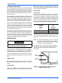
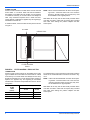
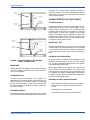
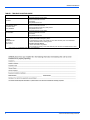
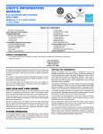
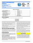
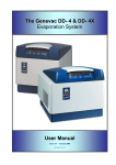
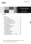
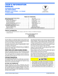
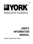
TABLE OF CONTENTS GENERAL INFORMATION . . . . . . . . . . . . . 2 HOW YOUR HEAT PUMP WORKS . . . . . . . . . . 2 SYSTEM OPERATION . . . . . . . . . . . . . . . . . 2 HEATING CYCLE . . . . . . . . . . . . . . . . . . . . . . . . 2 COOLING CYCLE . . . . . . . . . . . . . . . . . . . . . . . . 2 AIDS TO MAXIMUM OPERATING EFFICIENCY . . . . . . . . . . . . . . . . . . . . . . . . . 2 HEATING CONSERVATION . . . . . . . . . . . . . . . . 2 COOLING CONSERVATION . . . . . . . . . . . . . . . 3 USER’S, MAINTENANCE and SERVICE INFORMATION MANUAL MAINTENANCE . . . . . . . . . . . . . . . . . . . . . . 3 LUBRICATION . . . . . . . . . . . . . . . . . . . . . . . . . . 3 FILTER CARE . . . . . . . . . . . . . . . . . . . . . . . . . . . 3 AIR FILTERS . . . . . . . . . . . . . . . . . . . . . . . . . . . . 3 REGISTERS . . . . . . . . . . . . . . . . . . . . . . . . . . . . 5 CONDENSER COIL . . . . . . . . . . . . . . . . . . . . . . 5 BLOWER ASSEMBLY . . . . . . . . . . . . . . . . . . . . 5 CHARACTERISTICS OF HEAT PUMPS . . . 5 3 THRU 20 TO N SINGLE PACKAGE HEAT PUMP UNITS The manufacturer recommends that the “User” read all sections of this manual and keep the manual for future reference. A CONSTANT HEAT . . . . . . . . . . . . . . . . . . . . . . 5 WATER RUN - OFF . . . . . . . . . . . . . . . . . . . . . . 5 OUTDOOR COIL DEFROSTING . . . . . . . . . . . . 5 BEFORE CALLING A SERVICE PERSON . . . . . 5 820900-UUM-B-0913 820900-UUM-B-0913 Congratulations... on your purchase of our heat pump. This energy efficient unit has been precision designed, manufactured of high-quality materials and has passed many rigorous inspections and tests to ensure years of satisfactory performance. Please read this booklet thoroughly. It will help you understand your heat pump and will tell you how to operate it efficiently and how to obtain the greatest measure of comfort at the lowest operating expense. We appreciate your interest in our products and your decision to purchase our heat pump. Enjoy your comfort. The Main power to the system must be kept “On” at all times to prevent damage to the outdoor unit compressor. If necessary, the thermostat control switch should be used to turn the system “Off”. Should the main power be disconnected or interrupted for 8 hours or longer, DO NOT attempt to start the system for 8 hours after the power has been restored to the outdoor unit. If heat is needed during this 8 hour period, use emergency heat. HEATING CYCLE This heat pump has been specially developed and built to meet dual needs of heating and cooling. That’s why you can rely on efficient, trouble-free operation. With the thermostat in the heating position, and outdoor temperature in the range of 20 - 30 or below, the outdoor unit will generally run 100% of time. Your system is fully automatic. Set the thermostat and forget it. And it’s automatically protected against damage by voltage fluctuations or excessive heating or cooling demands. When the outdoor air is cool and moist, frost may form on the surface of your outdoor coil. When this frost builds to a certain point, your system will switch to a defrost cycle. Although you may feel cooler air coming from your registers, DO NOT adjust your thermostat. This frost will melt quickly, and your system will return to normal operation automatically. GENERAL INFORMATION HOW YOUR HEAT PUMP WORKS COOLING CYCLE If your hand is wet and you blow on it, it feels cool because some of the moisture is evaporating and becoming a vapor. This process requires heat. The heat is being taken from your hand, as your hand feels cool. Switch your thermostat to cool. Select a comfortable thermostat temperature setting, typically between 75 and 80 degrees. Comfort sensations vary with individuals.The lower the indoor temperature desired, the greater the number of hours your unit must operate. That’s what happens with a heat pump. During the cooling cycle, your system will remove heat and humidity from your structure and will transfer this heat to the outdoor air. Set your thermostat 2 or 3F below normal several hours before entertaining large groups during hot weather. People give off considerable heat and moisture. During the heating cycle, your system will remove heat and humidity from the outdoor air* and will transfer this heat to your structure. Remember that your heat pump doesn’t generate much heat, it merely transfers it from one place to another. On an extremely hot day, the indoor temperature may rise 3 to 6F above the thermostat setting. Properly selected equipment does not have the capacity to maintain a constant indoor temperature during this peak load. Over-sizing your system to handle this peak load isn’t practical because the over-sized system would operate much less efficiently at all other conditions. *This is possible because even 0F outdoor air contains a great deal of heat. SYSTEM OPERATION Your thermostat puts full control of the comfort level in your structure at your fingertips. AIDS TO MAXIMUM OPERATING EFFICIENCY HEATING CONSERVATION Set your thermostat for heating or cooling. Find the temperature that is most comfortable for you, and then leave your thermostat alone. Manually moving the thermostat up or down to extreme settings will not speed up temperature changes. Avoid moving the thermostat up during heating - particularly where a demand type electric meter is installed. This will increase your operating cost substantially. 2 For the most efficient operation, keep storm windows and doors closed all year long. They not only help to insulate against heat and cold, but they also keep out dirt, pollen and noise. Closing drapes at night and keeping fire place dampers closed when necessary, will help you to retain the air you have already paid to heat. Johnson Controls Unitary Products 820900-UUM-B-0913 COOLING CONSERVATION To comfortably cool your home, your heat pump must remove both heat and humidity. Don’t turn your system off even though you will be away all day. On a hot day, your system may have to operate between 8 and 12 hours to reduce the temperature in your home to a normal comfort level. Keep windows closed after sundown. While the outdoor temperature at night may be lower than indoors, the air is generally loaded with moisture which is soaked up by furniture, carpets and fabrics. This moisture must be removed when you restart your system. The hotter the outside temperature, the greater the load on your system. Therefore do not be alarmed when your system continues to run after the sun has set on a hot day. Heat is stored in your outside walls during the day and will continue to flow into your home for several hours after sunset. Use your kitchen exhaust fan when cooking. One surface burner on “High” requires one ton of cooling. Turn on your bathroom exhaust fan while showering to remove humidity. You can also help your system in the summer by closing drapes or blinds and lowering awnings on windows that get direct sunlight. MAINTENANCE delivered by the blower, decreasing your units efficiency and increasing operating costs and wear-andtear on the unit and controls. AIR FILTERS 3 THRU 6 TON Units 3-6 Ton are shipped with 1" throwaway type air filters. The filter racks on 3-6 ton units will receive 1" or 2" filters. Filters can also be installed in the building at a suitable return air location if an economizer or outside air accessory is not used. Filters must always be used. They should be inspected once a month and thoroughly cleaned or replaced if it appears they are beginning to accumulate excessive dirt. Filter sizes and quantities are shown in the following table. THROWAWAY FILTER SIZES (Inches) QUANTITY PER UNIT (Nom, Tons) 3 - 6 TON 14 x 20 2 14 x 25 1 To install the filters, remove the filter access panel located to the left of the condensate drain connection as shown in Figure 1. NOTE: Filters must be installed with “Air Flow” arrows pointing inward -- toward the indoor coil. In the event the spacers in the filter section are removed, they must be reinstalled in their original position. Prior to any of the following maintenance procedures, shut off all power to the unit. In order to insure long and trouble free service from your system, we recommend periodic inspection, cleaning, lubrication and adjustment by your installing Dealer/Contractor. Be sure to ask about this service. Slide filters all the way into the filter racks provided. When more than one filter in a filter rack is required, they must butt each other when sliding into position. Replace the filter access panel. For those buildings with in-house maintenance, please follow the instructions listed below to care for your system. (2) 14" X 20" FILTERS LUBRICATION (1) 14" X 25" FILTERS Both the indoor blower motor and outdoor fan motor are permanently lubricated and require no maintenance. 3 - 6 TON FILTER CARE Filters must always be used and must be kept clean. When filters become dirt laden, insufficient air will be Johnson Controls Unitary Products FIGURE 1 - END VIEW LESS FILTER ACCESS PANEL 3 THRU 6 TON 3 820900-UUM-B-0913 3 THRU 12.5 TON All units contain four filters. The filter racks on these units will receive either 1" or 2" filters. Filters can also be installed in the building at a suitable return air location if an economizer or outside air accessory is not used. Filters must always be used. They should be inspected once a month and thoroughly cleaned or replaced if it appears they are beginning to accumulate excessive dirt. To install the filters, remove the filter access panel as shown in Figure 2. NOTE: Filters must be installed with “Air Flow” arrows pointing inward -- toward the indoor coil. In the event the spacers in the filter section are removed, they must be reinstalled in their original position. Slide filters all the way into the filter racks provided. When more than one filter in a filter rack is required, they must butt each other when sliding into position. Replace the filter access panel. F IL T E R S IN D O O R C O IL F IL T E R A C C E S S P U L L S FIGURE 2- FILTER ACCESS 3 THRU 12.5 TON 15 AND 20 TON All units contain 2" filters. Filters can be installed in the building at a suitable return air location if an economizer or outside air accessory is not used. Filters must always be used. They should be inspected once a month and thoroughly cleaned or replaced if it appears they are beginning to accumulate excessive dirt. Filter sizes and quantities are shown in the following table. THROWAWAY FILTER SIZES (Inches) 4 QUANTITY PER UNIT (Nom, Tons) 15 TON 20 TON 12 x 24 - 12 16x 20 4 - 16 x 25 4 - To install the filters, remove the filter access panel located to the left of the condensate drain connection as shown in Figure 3. NOTE: Filters must be installed with “Air Flow” arrows pointing inward -- toward the indoor coil. In the event the spacers in the filter section are removed, they must be reinstalled in their original position. Slide filters all the way into the filter racks provided. When more than one filter in a filter rack is required, they must butt each other when sliding into position. Replace the filter access panel. Johnson Controls Unitary Products 820900-UUM-B-0913 (4) 16" X 20" FILTERS INDOOR COIL operation. The entire blower assembly should be inspected annually. If the motor and wheel are heavily coated with dust, they can be brushed and cleaned with a vacuum cleaner. CHARACTERISTICS OF HEAT PUMPS CONDENSATE DRAIN CONNECTION (4) 16" X 25" FILTERS Heat pumps have a noticeably cooler supply air temperature than furnaces. The common practice of oversizing furnaces contributes to an "off-and-on-again" operation with short blasts of hot supply air. The heat pump system is sized more closely to the heating needs of your home. Heat is supplied at a lower temperature over a longer period of time to provide a more constant heat, and it may give you the impression that your system "never stops running". 15 TON (6) 12" X 24" FILTERS INDOOR COIL (6) 12" X 24" FILTERS CONDENSATE DRAIN CONNECTION 20 TON FIGURE 3 - END VIEW LESS FILTER ACCESS PANEL 15 AND 20 TON REGISTERS Supply and return air registers must be open when the unit is in operation. Furniture must not block airflow in or out of the registers. CONDENSER COIL An annual check and cleaning of the outdoor coil should be done. Clean any debris and dirt from the outside coil face with a brush being careful not to damage the fins. If extremely dirty, a hose can be used to wash the coil from the inside out while brushing a soapy solution on the outside. BLOWER ASSEMBLY Even with good filters properly in place, blower wheels and motors will become dust laden after long months of Johnson Controls Unitary Products A CONSTANT HEAT WATER RUN - OFF During the heating cycle, you may notice water running off the outdoor coil. Moisture from the air is condensed on the outside surface of the coil where it gathers and runs off. No need for alarm, your unit has not sprung a leak! OUTDOOR COIL DEFROSTING At certain outdoor conditions (low temperature, high humidity), frost may build up on the coil of the outdoor unit. In order to maintain heating efficiency, the system will automatically defrost itself. Water vapor rising from the outdoor unit is normal and is an indication of proper operation. The vapor cloud will only last for a few minutes. When the defrost cycle is completed, the system will automatically switch back to heating. Electric heat is automatically energized to maintain comfort during defrost. BEFORE CALLING A SERVICE PERSON • Check thermostat setting and insure thermostat is calling for heat or cooling. Check thermostat for lint, etc. • Check fuses or circuit breakers • Check filters for excessive dust accumulation 5 820900-UUM-B-0913 TABLE 1: TROUBLE SHOOTING GUIDE PROBLEM CORRECTION NO HEAT Check thermostat for proper setting Check circuit breaker and fuses. Check filters. Call qualified service man. NOT ENOUGH HEAT OUTDOOR UNIT NOT RUNNING Check thermostat for proper setting. Check circuit breaker and fuses. Switch thermostat to Emergency Heat position. Call qualified service man. NO COOLING Check thermostat for proper setting. Check circuit breaker and fuses. Check filters. Call qualified service man. ELECTRICAL POWER INTERRUPTION (ice, snow, or wind storms) Procedure Heating Season: 1. Switch thermostat to Emergency Heat.* 2. Leave Emergency Heat on for at least 12 hours after electrical power is re-established. 3. Switch thermostat back to Heating or Auto. Procedure Cooling Season: 1. Switch thermostat to Off position. 2. Do not switch to Cooling or Auto until electrical power has been re-established for 4 hours. *There will be no heat available until power is re-established 6 Johnson Controls Unitary Products NOTES Subject to change without notice. Printed in U.S.A. Copyright © 2013 by Unitary Products Group. All rights reserved. York International Corporation 5005 York Drive Norman, OK 73069 820900-UUM-B-0913 Supersedes: 820900-UUM-A-1011