1
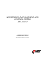
MONITORING, DATA LOGGING AND
CONTROL SYSTEM
MS5, MS5D
APPENDIXES
TO INSTRUCTION MANUAL
CONTENT:
page
APPENDIX 1: Power input of data logger ...................................................................................... 3
APPENDIX 2: Input circuits of data logger ..................................................................................... 6
APPENDIX 3: Input module RP ...................................................................................................... 8
APPENDIX 4: Communication cables ........................................................................................... 14
APPENDIX 5: Communication of data logger with computer....................................................... 18
APPENDIX 6: Configuration of data logger with external modem ................................................ 22
APPENDIX 7: Influence of cable resistance to measurement accuracy with RTD sensors .......... 24
APPENDIX 8: Selected error messages of data logger .................................................................. 25
APPENDIX 9: Support of reception and sending of SMS messages ............................................. 26
APPENDIX 10: Setting of communication with data logger via Ethernet ..................................... 28
APPENDIX 11: Creation of www pages for MS5 ......................................................................... 30
APPENDIX 12: SOAP protocol of Ethernet interface for MS5 ..................................................... 34
APPENDIX 13: Connection of data logger with output relay module and external terminal ......... 36
APPENDIX 14: Setting of client administration and passwords .................................................... 37
APPENDIX 15 Advanced settings of data logger .......................................................................... 48
Copyright: COMET System, Ltd. It is prohibited to copy and edit this instruction manual and make any
changes at all without explicit agreement of COMET System, Ltd. All rights reserved.
COMET System, Ltd makes constant development and improvement of all its products. That is why it
reserves the right to make any technical changes on the device/product without previous notice.
2
ie-ms2-ms5app-08
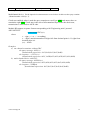
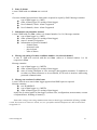
APPENDIX 1: Power input of data logger
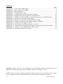
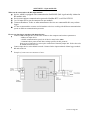
1. Wiring of power connector
2. Parameters of power input
Power voltage of data logger is 24V DC. Consumption of data logger differs depending on kind of
connected peripherals. Approximate values are in the below table. If output relay module will be
connected to data logger, this voltage must be complied. Data logger itself is able to work at power
voltage range (9..30)V DC. Always it is necessary to consider if A0 inputs will be installed before
selection of power voltage. If it is to be, see, what lowest power voltage transmitters connected to
this input need. Select data logger power voltage at least 3V higher than this. It is necessary to warn
negative pole of power connector is galvanically connected to internal GND of data logger. Thus
also with inputs (if galvanically not isolated) and with voltage of ALARM output.
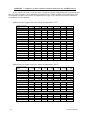
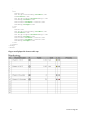
Approximate maximum current consumption
Power 24V
Power 9 V
Power 12V
data logger MS5 without input
modules
approximately 50 mA
approximately
100 mA
approximately
80 mA
data logger MS5D without
input modules
approximately 70 mA
approximately 180
mA
approximately
110 mA
Input modules galvanically not
isolated, CTU, CTK, FU, FK
except A0
< 1 mA
< 3 mA
< 3 mA
Input module galvanically
isolated and ac, RP, RS
approximately 10 mA
approximately
35 mA
approximately
25 mA
Input module A0*
20 mA max.
20 mA max.
20 mA max.
Output relay module, all relay
closed
approximately 200 mA
---
---
Ethernet interface
approximately 25 mA
approximately
40 mA
approximately
35 mA
approximately
approximately
20 mA
15 mA
SMS communication modules
approximately 6 mA
*A0 short circuited at the input has approximatelly 28mA current consumption
ie-ms2-ms5app-08
3
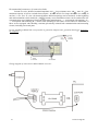
3. System back-up in case of mains power failure
In case data logger function is necessary to back up during power mains failure, first specify the current
consumption of the entire system. Then choose suitable back-up source in accordance with the required
time of uninterrupted operation. If there is a need to inform operating staff or distant user on battery
operation, then it is necessary to install binary input module S1 to any of input channels and connect it
with the backup source output signalizing battery operation.
When installing power sources it is necessary to follow valid safety regulations and
recommendations specified in instruction manuals of source manufactures. Leads to battery must be of
suitable cross-section size. In back-up design it is necessary to consider allowed temperature source a
battery.
Recommended back-up systems:
a) Back-up source AWZ224, manufacturer Pulsar sp.j., Poland
To this source it is necessary to buy two lead accumulators 12V/7Ah in hermetical maintenance-free
type of construction, e.g. type ELNIKA 12V/7.2Ah. Source is designed for mounting to vertical
inflammable wall with sufficient air flow. Its protection rate is IP20. It is not designed for mounting
to closed switchboard. More details are described in manufacturer instruction manual.
This back-up source is able to supply data logger with transmitters of current consumption 200mA
for approximately 35 hours. Discharged accumulators are recharged to full capacity in
approximately 14 hours.
Make basic wiring in accordance with instruction manual of the manufacturer. Connect data logger
this way: connect terminal –OUT of source to terminal GND of the power data logger connector,
connect terminal +OUT of source to terminal +Ucc. In case information for data logger on battery
operation is required, install input module S1 to data logger and connect second terminal +OUT of
source to terminal IN of this input and connect source terminal BS to terminal COM of input S1. In
user PC program state „OFF“ corresponds to „Mains operation“ and state „ON“ corresponds to
„Battery operation“. User can be informed on switch-over to battery operation by suitable adjustment
of conditions and alarms.
b) Back-up source MINI-DC-UPS/24DC/2 with batery MINI-BAT/24DC/1.3AH,
manufacturer Phoenix Contact
This source is designed for mounting to 35mm DIN rail in data logger case MP033 and
MP034. It contains two modules - UPS and battery. More details are described in manufacturer
instruction manual.
This back-up source is able to supply data logger system with 200 mA consumption at least 3 hours,
data logger system with 500 mA consumption at least 2 hours, data logger system with 1A
consumption at least one hour. Discharged accumulators are recharged to full capacity in
approximately 3 hours.
Make basic wiring in accordance with instruction manual of the manufacturer. Connect battery
(without fuse) with proper polarity to terminal +/- Battery, connect output of source –Out to terminal
GND of data logger power connector and source output +Out to data logger terminal +Ucc.
In case information for data logger on battery operation is required, install input module S1 to data
logger and connect terminal -OUT of source to terminal COM of this input and connect source
terminal Bat.mode to terminal IN of input S1. In user PC program state „OFF“ corresponds to
„Mains operation“ and state „ON“ corresponds to „Battery operation“. User can be informed on
switch-over to battery operation by suitable adjustment of conditions and alarms.
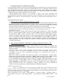
Example of backed up system:
There is a requirement to back up data logger MS5D with 10 input modules K1 and 6
modules A0. Three T3110 transmitters are connected to inputs A0. Data logger is connected to LAN
network via Ethernet interface and equipped with SMS module and external GSM modem Wavecom,
powered from the same source as data logger.
Total consumption of the system: 70mA (MS5D) + 10x1mA (10xK1) + 6x20mA (6xA0) +
40mA (Ethernet interface) + 6mA (SMS module) + approximately 100mA (GSM modem) = 346
mA.
4
ie-ms2-ms5app-08
By means of back-up source AWZ224 we are able to reach up to approximately 20 hours of
backed up operation, by means of system MINI-DC-UPS almost 3 hours of backed up
operation. It is supposed in described calculation, no short-circuit of current loops at input A0
appears. In opposite case current approximately 28mA/input A0 must be calculated.
ie-ms2-ms5app-08
5
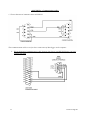
APPENDIX 2: Input circuits of data logger
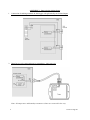
1. Connection of earthing terminals in data logger with galvanically not isolated inputs
2. Input for two-wire connected passive transmitters - input type A0:
Note: All temperature and humidity transmitters Comet are connectable this way.
6
ie-ms2-ms5app-08
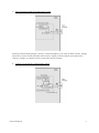
3. Input for measurement of current 0(4) to 20 mA
Inputs for measurement of higher currents (1A and 5A) differs by the value of shunt resistor. Voltage
inputs have resistor divider instead of shunt resistor. Inputs for measurement of resistance have
reference voltage via suitable resistor connected to the IN terminal.
4. Concept of galvanically isolated analog inputs
ie-ms2-ms5app-08
7
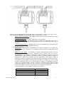
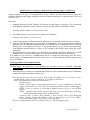
APPENDIX 3: Input module RP
What can be connected to the RP input module:
device, which is equipped with communication link RS485 (link is galvanically isolated at
RP module side)
device must support communication protocols ModBus RTU or ADVANTECH
1 to 16 input device can be connected to one module
Comet transmitters Tx4xx or other manufacturer devices are connectable this way to data
logger
it is not recommended to connect one RP module to devices working with different communication
speeds or different communication protocols
How to set data logger together with input devices:
Connect each from input devices one after another to the computer and set these parameters:
- address of input device
- suitable communication speed, for all device must be the same
- communication protocol and other settings specific for this protocol
Some types of input device can require connection of internal jumper Init. Follow the rules
in manual for these devices.
Connect input device to the RS485 network. Connect link to input terminals of data logger module
RP and switch on.
Example of connection to transmitter Comet:
8
ie-ms2-ms5app-08
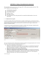
Run user SW for data logger and set the data logger: Configuration – Setting of data logger. Here
at bookmark Ch..Marking and conversions set for each channel these items:
- Device address (for RS485): enter address of input device operated from that data logger
channel.
- Communication speed – set speed, input device is set to before
- Maximum waiting time: time data logger will be waiting for response from input device
is adjustable from 30 to 210 ms. If response does not come within this time, error is
reported.
- Communication protocol – ModBus can be used (recommended) or Advantech. New
transmitters are usually set to ModBus protocol.
for ModBus protocol:
- source data – specification of transmitter space data are supposed to be gotten. For
Comet transmitter it is possible to use reading of storing registers or input port without
distinction.
- address of read register – enter address of register with required measured value for
specification of connected device. Address can be entered from 0 to 65535.
ATTENTION – this address corresponds to physical address of register. There are
different ways of specification of this address. That is why disagreement can appear, if
transmitter is adjusted by program from the manufacturer with address, which is
physically present in communication. Read carefully description of connected device.
Sometimes specified address equals to physical address of register (e.g. in case of RP
module). Sometimes shift of 1 is defined (entered address 1 corresponds to physical
address 0), sometimes shift of 40 000 or 40 001 is defined (entered address 40 001
corresponds to physical address 0). E.g. in the last case if in documentation is specified
data is at the address of 40 005, it is necessary to enter address of register 4.
Comet transmitters use these physical addresses of registers:
Value
Temperature
Relative humidity
Calculated humidity value
Barometric pressure
ie-ms2-ms5app-08
physical register address
48
49
50
51
9
-
format of data - must correspond to specification of the device, if addresses from above
table for Comet transmitter are used, use Signed format of data. Then set in Conversions:
measured value 0 corresponds to displayed value 0, measured value 10 corresponds to
displayed value 1.
Note: Comet transmitters also enable to read with better resolution in format float uC,
address of registers are then 8,10,12 and 14 for corresponding value. Support of float uC
format with these transmitters is not specified and guaranteed in documentation for
Advantech protocol:
- Multi-input device: If this input device measures more values, then tick this field. More
information – see below protocol description.
- Number of input channel: valid for multi-input device. It is a number from 0 to 7
- Check sum – must correspond to setting of the transmitter
After this setting RP module works with those inputs identically as with usual analog channels
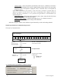
Detailed specification of communication protocol
Principle of communication:
MS5 datalogger
channels – time-division multiplex
Ch.1
query for
measured value
from RP module
Ch.16
response
transfer to/from specific protocol
layout
query for
measure value
response
IIC bus – communication between
MS5 and RP module
RP input module
Physical layout: RS485
Link layout:
ModBus RTU
Advantech
input
device(s)
A) Communication possibilities (common setting)
10
ie-ms2-ms5app-08
Connected device address, Baudrate and Parity options are noted in table above. Maximum wait
time (= Time out) ... is adjustable up to 210 ms approximately. After expiration of this duration
communication error is reported and module continues with reading of the following channel.
B) ModBus RTU transfer protocol
RTU ModBus message frame:
Connected
Function code
device address
1 byte
1 byte
Data
CRC
n byte
2 byte
Supported data request formats:
Connected
device address
1 byte
Function code
Starting address
No. of registers
CRC
0x03 or 0x04
2 byte (0...65535)
2 byte
2 byte
Data source:
RP module supports two function codes:
0x03 ... Read holding registers
0x04 ... Read input registers
other functions are not supported
Register address (= starting address):
absolute address of the first 16-bit reading register (address on the link layout),
range: 0...65535
Data format – RP input module is suitables for reading of continuous quantities. Every read value
is converted to 4 byte float (single) format for MS5. Data format item specifies No. of requested
registers and their conversion method to MS5 float format.
Possible options:
signed (-32768..32767) ... 2 byte, “integer” format, No. of registers = 1
unsigned (0...65535) ... 2 byte, “word” format, No. of registers = 1
signed (-32768..32767) ... 2 byte, “integer” format, No. of registers = 1
float IEEE754 ...4 byte, float format (register 0,register 1), No. of registers = 2
float IEEE754 ...4 byte, float format, (register 1,register 0), No. of registers = 2
float for uControllers ...4 byte, float format (register 0,register 1), No. of registers = 2
float for uControllers ..4 byte, float format, (register 1,register 0), No. of registers = 2
Data response format:
Connected
device address
ie-ms2-ms5app-08
Function code
Byte
count
Data
CRC
11
1 byte
1 byte
1 byte
ByteCount byte
2 byte
Function code in response is the same as in the request. If the exception occurs function code is
0x83 or 0x84 and data field contains error code.
Example:
Data request:
0x01, 0x03, 0x00, 0x30, 0x00, 0x01, 0x84,0x05
Data answer:
0x01, 0x03, 0x02, 0x01, 0x01, 0x78,0x14
data field: 0x0101 (257)
Data format of float expressions:
float IEEE754 No. 1 is expressed as 0x3F800000
float IEEE754 inverse No. 1 is expressed as 0x0000803F
float for uControllers No. 1 is expressed as 0x80000000
float for uControllers inverse No. 1 is expressed as 0x00000080
C) Advantech ASCII transfer protocol
Data request format:
start of
reading
#
Connected device
address
2 ascii byte
channel
number*
1 ascii byte
CRC*
end
2 ascii byte
0x0D
Data answer format:
start
reading
12
measured value
CRC*
end
ie-ms2-ms5app-08
>
n ascii byte
*...optionally
2 ascii byte
0x0D
Multichannel device: for the input devices that measures several values. In this case the query contains
„Channel number“ field (0...7).
Check sum enabled: when is used the query contains two ascii byte CRC and answer have to
contain the right CRC. Check sum is the sum of all transmitted byte before the check sum,
transmission is converted to ASCII code.
Module RP supports response format corresponding with "Engineering units" protocol
ADVANTECH:
>sxxxx.xxxx(CRC)(cr)
where
s ... sign („+“ or „-“ or nothing)
x ... digits, maximum number of digits left from decimal point is 11, right from
decimal point is 6
(cr) ... 0x0D
Examples:
a) one channel transmitter without CRC
the query message: #032(cr)
(hexadecimal expression: 0x23,0x30,0x33,0x32,0x0D)
the response: >+23.50 (cr)
(hexadecimal expression: 0x3C, 0x2B,0x32,0x33,0x2E,0x35,0x30,0x0D)
b) multi-channel device with CRC:
the query message: #032B8 (cr)
(hexadecimal expression: 0x23,0x30,0x33,0x32,0x42,0x38,0x0D)
the response: >358B(cr)
(hexadecimal expression: 0x23,0x33,0x35,0x38,0x42,0x0D)
ie-ms2-ms5app-08
13
APPENDIX 4: Communication cables
1.. Wiring diagram of communication cable RS232
This communication cable serves for direct connection of data logger to the computer.
3. Wiring diagram of communication cable between data logger and RS232/Ethernet converter
UDS10/100/1000
14
ie-ms2-ms5app-08
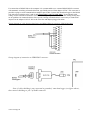
4. Wiring of RS485 terminals at data logger
5.
D4.4 The way of data loggers connection by means of RS485 interfaces
ie-ms2-ms5app-08
15
Recommended parameters of connection leads:
Twisted two-wire, shielded, nominal impedance 100 , loop resistance max. 240 , max. 98 /km,
maximum capacity 65 pF/m, crosstalk between pairs –40 dB/150 kHz. For longer distances use cabling in
one line, i.e. no „tree“ or „star“ (for shorter distances different topology can be tolerated). At the beginning
and end termination resistor should be (120
In many cases termination resistor can be omitted due low
communication speed. Marking of link leads from other manufacturers: „+“ corresponds with marking „A“,
„-“ corresponds with marking „B“. Connect cable shielding to each other, do not connect to transmitter, if
those are not equipped with shielding terminal galvanically isolated from communication and measuring
circuits, including case metal parts.
In case shielding of RS485 link is not possible to ground at computer side, ground at data logger nearest to
the computer:
Wiring diagram of connection to RS232/RS485 converter:
16
ie-ms2-ms5app-08
For connection of RS485 link to the computer it is recommended to use external RS485/RS232 converter
with automatic switching of transfer direction, type E06D powered from adapter 6V DC. This converter is
possible to plug to serial communication computer port COM. Connect link from data logger to the RS485
side with correct polarity (pins 3 and 4) and connect pins 2 and 7 to each other . It corresponds with
setting of time constant of automatic converter switching for speed 115200 Bd. At this setting mostly there
are no problems in communication at lower speed). During communication it is necessary to connect DC
output of ac/dc adapter 230V/6V DC to the converter and adapter plugged in mains.
Wiring diagram of cable between data logger and RS485/Ethernet converter UDS10/100/1000
Wiring diagram of connection to USB/RS485 converter:
Note: if cable shielding is not connected to ground of some data logger (see figure above),
then connect shielding to pin 5 of SubD connector.
ie-ms2-ms5app-08
17
APPENDIX 5: Communication of data logger with computer
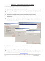
1. Connection of data logger to computer by means of RS232 interface
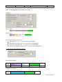
Connect data logger to the computer and switch on its power.
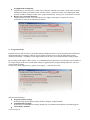
Select menu item Configuration – Communication settings in the software and continue by option
New in the section Communication interface. Choose USB/RS232 option in wizard window and
press Next button.
Select number of COM port, baudrate, set option Autobaudrate and click Next button.
In the final window of the wizard confirm or change name of the interface (combination of letters
and digits only)
Confirm window and press button Search. Program goes through all used communication speeds
and displays found data loggers in bottom window part (Dataloggers). Window of Communication
settings finally confirm (button OK).
Note: 230400 Bd baudrate is unsupported for standard PC COM port
2. Connection of data logger to computer by means of USB interface
Procedure is the same as in previous case. USB interface is interpreted in the computer as Virtual
COM port. Drivers would be installed automatically during installation of the SW. Drivers are
available also on installation CD or at www.cometsystem.cz .
If you disconnect the converter from the computer, it can happen, data logger will not be found in the next
18
ie-ms2-ms5app-08
communication. The cause is, operation system assigned to converter different number of communication
port. You can change it in the above window of communication device or in operation system – Device
Administrator, COM and LPT ports – Parameters – Specify.
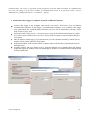
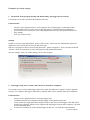
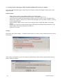
3. Connection of data logger to computer by means of Ethernet interface
Connect data logger to the computer and switch on its power. There have to be set Ethernet
communication interface in data logger. If communication interface is set to RS232, data logger
may communicate but extended ethernet functions (services) will be unavailable (warning e-mails,
traps, SOAP, Syslog, web).
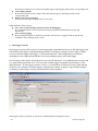
Select menu item Configuration – Communication settings in the software and continue by option
New in the section Communication interface. Choose Ethernet option in wizard window and press
Next button.
Enter IP address of data logger (if you do not know you can search the network by button Search),
number of port (10001) and click Next button.
In the final window of the wizard confirm or change name of the interface (combination of letters
and digits only)
Confirm window and press button Search. Program performs test communication and displays
found data loggers at window lower part (Dataloggers). Window of Communication settings finally
confirm (button OK).
ie-ms2-ms5app-08
19
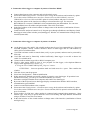
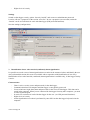
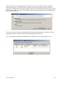
4. Connection of data logger to computer by means of interface RS485
Connect data loggers to the computer and switch on their power.
Select menu item Configuration – Communication settings in the software and continue by option
New in the section Communication interface. Choose Converter RS232/RS485, converter
USB/RS485 or Converter Ethernet/RS485 option in wizard window and press Next button.
Set particular options of the interface according to selected interface type. For converter
RS232/RS485 or converter USB/RS485 select communication port and baudrate. For converter
Ethernet/RS485 enter IP address and port number. Then click Next button.
In the final window of the wizard confirm or change name of the interface (combination of letters
and digits only).
Confirm window and press button Search. Program goes through all addresses and displays found
data loggers in the bottom window part (Dataloggers). Window of Communication settings finally
confirm (button OK).
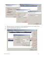
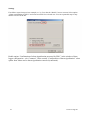
5. Connection of data logger to computer by means via modem
At the data logger side and PC side suitable modem must be used (recommended type: Wavecom
M1306B, Supreme, Xtend). Connect interfaces RS232 of data logger and PC with modems by
cables, delivered with modems.
Used SIM card must enable to transfer data (verify at your operator) and must not be protected by
PIN code.
Used SIM card must be financially credited sufficiently. Data logger is not able to detect low
credit! Use suitable tariff.
Connect modem at data logger side to RS232 computer port.
Click by right mouse button to icon of user program for data logger, select Options-ShortcutTarget, where append text of /master, e.g.:
"C:\Program Files\COMET\MS234p\Ms_234p.exe" /master
ATTENTION – between quotation mark and slash must be a space. Then confirm the
window.
Click this icon to run the program.
Select item Configuration – Modem initialization.
If this operation is finished successfully, modem is properly set to data logger. If operation is not
finished successfully, you can try to set modem manually (see below).
Disconnect configured modem from computer and connect it to data logger.
By means of the keyboard set on data logger display communication interface RS232-modem,
communication speed 9600Bd.
Connect second GSM modem to the computer.
Select menu item Configuration – Communication settings in the software and continue by option
New in the section Communication interface. Choose Modem (RS232) option in wizard window and
press Next button.
Select number of COM port, where modem is connected and communication parameters. Some
modem types work only on speed 9600 Bd. Select Tone dialing and input Modem initialization
string to AT&D2. Then click Next button.
In the final window of the wizard confirm or change name of the interface (combination of letters
and digits only)
20
ie-ms2-ms5app-08
In the part Dataloggers select option New. Select communication interface, enter telephone number
of modem at the data logger side and save settings (button OK).
Perform communication test (button Test).
ie-ms2-ms5app-08
21
SIM cards of both modems must enable data transfers and must not be blocked by PIN code. More
information concerning solution of problems is specified in Appendix 6.
APPENDIX 6: Configuration of data logger with external modem
When there is a need to connect datalogger via telephone network (land line or GSM) the
configuring of GSM modem on datalogger side is necessary. Connect modem to computer by a
cable, which is the accessory of the modem, plug in the ac/dc adapter and switch ON the modem.
Bellow is mentioned “manual” setting by Hyperterminal.
Instructions for "manual" communication setting by means of modems:
Configuration of data logger´s communication interface
Connect data logger via RS232 link to the computer (included cable), switch on and run user
PC program. Choose selection RS232- modem from Configuration menu.
Configuration of external modem at data logger side
Run HyperTerminal program on your computer (it is located in Accessory - Communication).
After its running a request of creation of new connection appears. Cancel this request. In menu File
- Parameters choose in item Connect by means of selection Directly to port COM1 (respectively
COM2, if modem is connected to communication port COM2). Choose selection Configuration at
the same window and set parameters Number of bits per second to 115200, Number of data bits to
8, Parity: no, Stop-bits: 1, Flow control: hardware. Confirm both windows to return to terminal.
Here enter command AT (cr) (i.e. enter in upper case letters AT and press the Enter key). Modem
must response: OK.
Setting of modem for land line
Now it is necessary to configure modem itself in the way modem after reception must
"hung-up" (disconnect the call) and cancel the control of the DTR-DSR loop. This can be done as
follows:
a) AT&Y0 cr (selection of user template 0)
b) ATS0=1 cr (modem „hang-up after the call”)
c) ATS23=060 cr (communication speed 19200 Bd)
d) AT&D1 cr (cancel of testing DTR-DSR loop)
e) AT&W0 cr (saving of active configuration to profile 0)
Now modem is configured and can be switched OFF. Modem responds OK to each commands.
Notice: Be careful not to send to modem AT command in other communication speed. It could
cause modem reconfiguration.
Note: The above description was verified with modems Microcom DeskPorte 56k Voice, ASKEY V
1456 VQE R-1 and ORIGO FM-56DT.
Setting of GSM modem - SIM card used in GSM modem must be set not to require PIN after switching ON
the modem power. Modem should be set to automatically pick up the call and to enter data
mode immediately.
Example for GSM modem WAVECOM Supreme, Xtend:
a) AT&F cr (factory default)
22
ie-ms2-ms5app-08
b) AT+IPR=9600 cr (serial interface of modem sets to 9600 Bd)
c) now is neccessary to change Hyperterminal baudrate to 9600Bd
d) AT+CICB=0 cr (automatic jump to data mode)
e) ATS0=1 cr (automatic call pick-up after first ring)
f) AT&D0 cr (DTR is ignored)
g) AT&S0 cr (DSR always ON)
h) ATE0 cr (ECHO off)
i) AT&W cr (configuration writing to EEPROM memory).
What to do if connection does not work
If communication via modems does not work and data logger itself communicates with the computer,
check first if wiring and each setting are correct. Pay attention to connection cables, which must be original
to modems. Cable included in data logger is designed only for direct connection between computer and data
logger. If everything is correct it is useful to test communication between two computers. Modem, which
was at data logger side connect to the first computer and run Hyperterminal. Connect modem, which was at
the computer to the second computer (it is supposed, it is already installed) and also run Hyperterminal.
Here in contrary with the first computer create new connection with telephone number of link, first modem
is connected to. Now there is no other way out than take modem user manual and try to create bothdirection data connection at suitable communication speed.
ie-ms2-ms5app-08
23
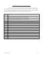
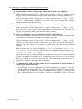
APPENDIX 7: Influence of cable resistance to measurement accuracy with RTD sensors
In case inputs J (Ni1000), K (Pt100) or K1 (Pt1000) are installed and RTD probe is connected, then
non zero cable resistance causes additional measurement error, which is added to real temperature. This
error depends on cable cross-section, its length and sensor type. If it is known correction is enabled by
recalculation of input channels.
Added error for copper wire (two wires) at temperature 23°C:
Cable cross-section
[mm2]
0,22
0,34
0,50
1,00
1,50
2,00
2,50
Added error for Ni1000/6180ppm [°C]
Cable length [m]
1
2
5
10
0,02
0,04
0,12
0,24
15
0,36
0,01
0,03
0,07
0,15
0,01
0,02
0,05
0,10
0,00
0,01
0,02
0,05
0,00
0,00
0,01
0,03
0,00
0,00
0,01
0,02
0,00
0,00
0,01
0,02
0,23
0,16
0,08
0,05
0,04
0,03
Added error for Pt100/3850ppm [°C]
Cable length [m]
1
2
5
10
0,36
0,73
1,82
3,64
0,24
0,47
1,18
2,36
0,16
0,32
0,80
1,60
0,08
0,16
0,40
0,80
0,05
0,11
0,27
0,53
0,04
0,08
0,20
0,40
0,03
0,06
0,16
0,32
15
5,47
3,54
2,40
1,20
0,80
0,60
0,48
Added error for Pt1000/3850ppm [°C]
Cable length [m]
1
2
5
10
0,04
0,07
0,18
0,36
0,02
0,05
0,12
0,24
0,02
0,03
0,08
0,16
0,01
0,02
0,04
0,08
0,01
0,01
0,03
0,05
0,00
0,01
0,02
0,04
0,00
0,01
0,02
0,03
15
0,55
0,35
0,24
0,12
0,08
0,06
0,05
1,50
2,00
2,50
Added error for copper wire (two wires) at temperature 100°C:
Cable cross-section
[mm2]
0,22
0,50
1,00
Added error for Ni1000/6180ppm [°C]
Cable length [m]
1
2
5
10
0,02
0,04
0,10
0,20
15
0,30
0,01
0,02
0,06
0,13
0,01
0,02
0,04
0,09
0,00
0,01
0,02
0,04
0,00
0,00
0,01
0,03
0,00
0,00
0,01
0,02
0,00
0,00
0,01
0,02
0,20
0,13
0,06
0,04
0,03
0,02
Added error for Pt100/3850ppm [°C]
Cable length [m]
1
2
5
10
0,37
0,75
1,86
3,73
15
5,60
0,24
0,48
1,21
2,41
0,16
0,33
0,82
1,64
0,08
0,16
0,41
0,82
0,05
0,11
0,27
0,55
0,04
0,08
0,21
0,41
0,03
0,07
0,16
0,33
3,62
2,46
1,23
0,82
0,62
0,49
Added error for Pt1000/3850ppm [°C]
Cable length [m]
24
0,34
1
2
5
10
0,04
0,07
0,19
0,37
0,02
0,05
0,12
0,24
0,02
0,03
0,08
0,16
0,01
0,02
0,04
0,08
0,01
0,01
0,03
0,05
0,00
0,01
0,02
0,04
0,00
0,01
0,02
0,03
15
0,56
0,36
0,25
0,12
0,08
0,06
0,05
ie-ms2-ms5app-08
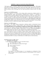
APPENDIX 8: Selected error messages of data logger
This error messages you can see on data logger’s LCD, among measured values or during
some actions in software. If software reports error message, take care on sign of this error number. Positive
errors are evaluated by datalogger and their decription is in the table below. Negative errors are evaluated
by software. In this case additional text in message specify what problem appeared.
Error
number
1
MEANING
3
A/D converter is at lower limitation (input quantity – is below lower limit of module range)
or for RP input module & Advantech protocol: >-0000 response
A/D converter is at upper limitation (input quantity – is over upper limit of module range)
or for RP input module & Advantech protocol: >+9999 response
RS , RP input module did not receive response from connected device in adjusted time
4
RP input module: invalid CRC
5
RP input module & Advantech protocol: invalid character in response
6
RP input module & Advantech protocol: invalid character in response
7
RP input module & ModBus protocol: unknown function code
8
RP input module & ModBus protocol: ModBus exception occurs
9
RP input module & Advantech protocol: too long response
10
counter module does not contain valid data
130
input module was not found
137
counter value is not possible to display (it contains more than 10 digits) – only display error
149
RP input module: unknown transfer protocol
160-177
corruption of configuration areas of data logger
178
installed different type of module
179
upgrade of input module was not performed
187-188
unauthorized access (non valid password)
189
error of measurement of thermocouple cold junction
2
ie-ms2-ms5app-08
25
APPENDIX 9: Support of reception and sending of SMS messages
Data logger enables to respond to SMS query and sending SMS alarm messages. GSM modem
connected to data logger must support PDU SMS format and its SIM card must have stored SCA
number (Service Center Address). SIM card must not be blocked by PIN code and must have
sufficient financial credit. Data logger does not enable monitoring of financial credit of the SIM
card.
Format of received SMS messages:
PDU format, support of 7 bit, 8 bit a 16 bit coding without compression, telephone number in
international/national format, ISDN/telephone numbering plan, maximum 15 characters of
telephone number, maximum length of text message 64 characters, message can contain UDH of
36 character maximum length, TP-PID= 00h (Short Message Type 0). If those parameters are
matched, message is accepted and decoded by data logger, i.e. UDH block is removed, text is
converted to capital letters and compared with predefined strings: Info, Alarm, Ch1 to Ch16, Set1
to Set16, Clr1 to Clr16. In case valid string was received (no matter if capital/lower-case letters),
data logger sends proper response and received message is cleared from modem. If received SMS
message is not valid it is cleared from modem without sending any response.
Format of sent SMS messages:
PDU format, 7 bit coding without compression, telephone number in international format
maximum length 15 characters, Validity period: 3 days, with all messages except response to
request Info one SMS is sent of maximum 160 characters. In response to request Info sequence of
one to four SMS messages is sent (depending on configuration of data logger), maximum length is
152 characters for a message. Messages contain UDH with code for linking to one long SMS on
mobile telephones, which support linking of SMS together. For proper function it is necessary to
have telephone number SCA (Service Center Address) stored on SIM card of the modem.
With messages sent due to creation of alarm or critical state, after SMS is sent all alarm
states in data logger are stored. If no change in alarms appears, another message is not sent. If
alarm stops to be active and appears again, message is sent. If alarm at another channel appears,
message is sent again (If it is allowed by the user). If critical error state for sending SMS appeared
(defined delay expired) and before sending of this SMS appeared new critical states, the states are
included into the SMS. It is always recommended to set suitable hysteresis and alarm delay.
Detailed description of SMS content:
1. Information on data logger
is sent if SMS with text Info was received. Then SMS contains:
type of data logger (e.g. MS5)
name of data logger (see setting of data logger)
state of memory occupation
for each channel:
- channel name
- measured value
- physical unit
- state of alarms
Total number of sent SMS messages is 1 to 4 depending on configuration of data
logger. Messages contain information intended for linking together at the recipient to
one long SMS.
26
ie-ms2-ms5app-08
2. State of alarms
is sent if SMS with text Alarm was received
or
if at some channel appeared new alarm and is required its report by SMS. Message contains:
type of data logger (e.g. MS5)
name of data logger (see setting of data logger)
list of channels, where Alarm 1 appeared
list of channels, where Alarm 2 appeared
3. Information on particular channel
is sent if SMS with text Chn (where n is channel number 1 to 16). Message contains:
type of data logger (e.g. MS5)
name of data logger (see setting of data logger)
state of memory occupation
information on specified channel:
- channel name
- measured value
- physical unit
- state of alarms
4. Message on setting of remote condition number 4 at selected channel
is sent, if SMS was received with the text Setn (where n is channel number 1 to 16)
respectively Clrn.
Message contains:
type of data logger (e.g. MS5D)
name of data logger (see setting of data logger)
state of setting condition or error message (unacceptable statement, if condition is
set other way than to Remote or Access denied, if PIN code is incorrect while using
protected communication
5. Message on creation of critical state
is sent if critical error state in data logger appeared and SMS report is required.
Message contains:
text WARNING!
type of data logger (e.g. MS5D)
name of data logger (see setting of data logger)
actual list of critical states in data logger (selftest error, configuration, measurement, overrun
of adjusted limit, fulfilling of memory)
Some other settings concerning communication between data logger and modem (If linking of SMSs
is used, how some error states are solved, etc.) are specified in Advanced options tab and are described
in Appendix 15.
ie-ms2-ms5app-08
27
APPENDIX 10: Setting of communication with data logger via Ethernet
Setting depends on type of communication device. Below are described general steps and
examples illustrate data logger equipped with own Ethernet interface or with converter UDS-1000
from Lantronix.
Procedure:
1. Probably knowing of MAC address of converter or data logger is necessary (if it is equipped
with Ethernet interface). MAC address is mostly specified on the manufacturer label.
Example of MAC address: 00-20-4A-80-F2-FB
2. Ask administrator of your network to assign free IP address
Example of IP address: 194.168.1.211
3. Connect data logger to Ethernet network (directly or via converter) and switch on its power
4. Run user SW for data logger and in window Configuration - Setting communication display
parameters of the Ethernet communication device (button New or Change) and use selection
Search (next to IP address). If device is not found (detect e.g. by means of disconnecting
from Ethernet network and see, if there is any change in the search), then follow the below
instruction.
5. If connection is not successful, try to disconnect the computer from the network, use crossed
Ethernet cable to connect data logger to the computer directly and repeat the settings.
If IP address is set correctly, communication device is found, but data logger does not work,
check setting of Communication interface. Best way is to check on display of data logger: must
be set to Ethernet.
Solving problems with communication:
A) data logger is connected to the network by external converter (UDS100, UDS1000,
UDS1100...):
Problem can be in setting of communication interface and communication speed of Ethernet
output itself. In this case proceed this way:
Run internet browser and enter directly data logger IP address (it is necessary to have
installed Java script), wait for reading of www pages of this device.
Enter at bookmark Port Properties or Channel 1:
- Serial protocol:
RS232, if data logger contains Ethernet interface or you communicate with data
logger connected to converter UDS-10 connected to RS232 interface of data logger
RS485-2 wire, if converter is connected to RS485 interface of one or several data
loggers
- Speed – communication speed, must be the same, as set on data logger itself (can
be found from data logger menu of MS5D LCD)
- Character Size: 8, Parity: None, Stopbit: 1, Flow Control: None, UDP Datagram
Mode: Disable, Remote IP Address: same as used before, Local Port: 10001,
Disconnect Mode: Ignore DTR, Other items: Disabled
Save the configuration to the device finally and try to find data logger again.
28
ie-ms2-ms5app-08
B) Data logger is equipped with internal Ethernet interface
In the window of device finding only IP and MAC address are displayed
Other details are marked as N/A. This problem appears in case, IP address of data
logger is set to different network, than network data logger is actually connected to.
Select in program menu Configuration - Setting communication – Change – Find Change IP and change IP address to new one. The rest of settings leave without
changes and press the button Change.
IP address is not displayed even in the window for device finding
Select in program menu Configuration - Setting communication – Change – Find Help! My device wasn’t found!. Input MAC address of the device (e.g. 00-20-4A-84F0-80), assign new IP address and press the button Change.
Device is not found even after manual entering of MAC address
This problem appears especially in cases, IP device belongs to different network and
at the same time incorrect gate address and mask is specified.
Select in program menu Configuration - Setting communication – Change – Find Change IP. Input MAC address of the device (e.g. 00-20-4A-84-F0-80), assign IP
address, check the option Set IP address to ARP table only and press the button
Change.
Run command line of system Windows (Start/run) and enter telnet new
IP_address 9999. You get to the text mode of setting data logger interface (e.g.:
telnet 192.168.1.211 9999).
Press enter key and 0 - Global Settings, set IP address of the device, cancel IP address
of gate, set number of mask bits to 0. Confirm the rest by enter key to get to menu.
Here save setting by selection 9 Save and Exit. Then connection is closed. Now it is
possible to connect to data logger by the program.
Communication with program works, but it is not possible to change setting of
data logger Ethernet interface
If data logger is set to communicate with the program (it is possible to read the
Display mode, download data etc.), but configuration of Ethernet interface cannot
be changed (e.g. IP address of traps, IP address of data logger…), probably you
have adjusted high level of security. Proceed in accordance with the Service
manual.
ie-ms2-ms5app-08
29
APPENDIX 11: Creation of www pages for MS5
Data logger enables user to store own web pages to display actual measured values and alarm
states. Files web2cob.exe, mimetype.ini, ron.gif, al2.gif, alarm.gif, led.gif will be
necessary for successful creation of own www pages. Download files from manufacturer pages.
Also tftp client is necessary (default in Windows XP).
Pages are created in html code, web server of data logger detects the GET command. Data
logger has available six banks WEB1-6 after 64kB for www pages.
Address of www pages is http://IP_address_data logger/page.html. If your main page is
named index.html, only enter data logger IP address in internet browser to address of pages.
Procedure of www pages creation:
Create HTML pages in any editor. Enter proper mark to the point where values from data logger
are meant to be located:
<%srn%>
<%name%>
<%rfr%>
<%type%>
<%fw%>
serial number of data logger
name of data logger
refresh of pages
data logger model
version of firmware of data logger Ethernet interface (it is different from FW
version of data logger itself)
<%iacs%>
<%oacs%>
<%iap%>
<%oap%>
<%tico%>
<%slft%>
<%ram%>
state of internal audio indication
state of ALARM OUT output
icon of state of internal audio indication
icon of state of output ALARM OUT
icon of selftest state
values measured by selftest
state of memory occupation and logging mode
Valid for all 16 channels; enter 1 for required channel:
<%c1n%>
name of channel 1
<%c1v%>
measured value
<%c1u%>
physical unit of the value
<%c1a%>
state of alarm 1
<%c1b%>
state of alarm 2
<%c1p%>
name of actual process
<%c1r%>
information, if record runs
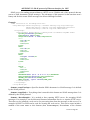
Example:
Example of the code :
<!DOCTYPE HTML PUBLIC "-//W3C//DTD HTML 4.01 Transitional//EN">
<html>
<head>
<meta http-equiv="refresh" content="<%rfr%>">
<meta http-equiv="content-type" content="text/html; charset=windows-1250">
<title>values</title>
<style type="text/css">
<!-body{ font-family: verdana, arial, helvetica, sans-serif; font-size: 76%;
color: #000; background-color: #fff; }
ie-ms2-ms5app-08
30
h1 { font-size: 2.0em;
0em; }
.a1 {background-color:
.a2 {background-color:
.a0 {background-color:
//-->
</style>
</head>
<body>
<script>
p1 = new Image();
p1.src = "ok.gif";
p2 = new Image();
p2.src = "al1.gif";
p3 = new Image();
p3.src = "al2.gif";
p4 = new Image();
p4.src = "ron.gif";
</script>
font-weight: normal;margin-top: 0em; margin-bottom:
red;}
yellow;}
#d3d3d3;}
<h1>Monitoring:</h1>
<table border="1" cellpadding="2" cellspacing="0">
<tr bgcolor="#bbbbbb">
<td><b>Nr.</b></td>
<td width="180px" align="center"><b>Channel name</b></td>
<td><b>R</b></td>
<td width="180px" align="center"><b>Value</b></td>
<td width="80px" align="center"><b>Unit</b></td>
<td width="20px" align="center"><b>I.</b></td>
<td width="20px" align="center"><b>II.</b></td>
<td width="180px" align="center"><b>Process</b></td>
</tr>
<tr>
<td>1</td>
<td align="left"> <%c1n%></td>
<td><%c1r%></td>
<td align="right"><%c1v%> </td>
<td> <%c1u%></td>
<td><center><%c1a%></center></td>
<td><center><%c1b%></center></td>
<td> <%c1p%></td>
</tr>
<tr>
<td>2</td>
<td align="left"> <%c2n%></td>
<td><%c2r%></td>
<td align="right"><%c2v%> </td>
<td> <%c2u%></td>
<td><center><%c2a%></center></td>
<td><center><%c2b%></center></td>
<td> <%c2p%></td>
</tr>
<tr>
<td>3</td>
<td align="left"> <%c3n%></td>
<td><%c3r%></td>
<td align="right"><%c3v%> </td>
<td> <%c3u%></td>
<td><center><%c3a%></center></td>
<td><center><%c3b%></center></td>
<td> <%c3p%></td>
</tr>
ie-ms2-ms5app-08
31
…
…
<tr>
<td>15</td>
<td align="left"> <%c15n%></td>
<td><%c15r%></td>
<td align="right"><%c15v%> </td>
<td> <%c15u%></td>
<td><center><%c15a%></center></td>
<td><center><%c15b%></center></td>
<td> <%c15p%></td>
</tr>
<tr>
<td>16</td>
<td align="left"> <%c16n%></td>
<td><%c16r%></td>
<td align="right"><%c16v%> </td>
<td> <%c16u%></td>
<td><center><%c16a%></center></td>
<td><center><%c16b%></center></td>
<td> <%c16p%></td>
</tr>
</table>
</body>
</html>
Pages are displayed in browser this way:
32
ie-ms2-ms5app-08
Compilation and upload of pages
Store pages for upload to data logger to one directory. The above required pictures store to the
same directory with you r pages. Run program web2cob.exe to create .cob file. Upload this file
by means of tftp protocol to data logger.
Parameters of program web2cob.exe:
Web2CoB [/o <output file>] [/d <directory>]
Output file: Name of output file. Preset name is cobox.cob.
Directory: Source directory with www pages.
Parameters of tftp transfer: select binary transfer, method PUT. Select target address from
WEB1 to WEB6.
Note: File mimetype.ini must be located in the same directory as Web2Cob.exe
Example:
Data logger has IP address 192.168.1.205. In directory c:\MS\www are located www pages.
In directory c:\MS are files Web2Cob.exe and mimetype.ini. Go to the directory c:\MS and
enter command:
web2cob.exe /d www /o TESTWEB.cob
In directory c:\MS file TESTWEB.cob is created.
Upload www pages to data logger by command tftp -i 192.168.1.205 PUT TESTWEB.COB
WEB1, memory area WEB1
Limitation:
Maximum size of one WEB (cob) page is 64kB. In case size of www page exceeds 64kB,
divide it to max. 6 blocks, compile one after another and store to areas WEB1-WEB6
Each tag of type <% %> must be located on separate line in source file.
Capacity of www server of data logger is limited. The bigger the pages are, the lower number of
possible simultaneous accesses will be.
ie-ms2-ms5app-08
33
APPENDIX 12: SOAP protocol of Ethernet interface for MS5
SOAP serves for sending measured data to a HTTP server. With the aid of this protocol data are
sent as a XML document (SOAP message). The advantage of this protocol is that sent data aren’t
binary and for this reason SOAP messages are allowed through firewalls.
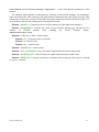
Example:
<?xml version="1.0" encoding="utf-8"?>
<soap:Envelope xmlns:soap=http://schemas.xmlsoap.org/soap/envelope/
xmlns:xsi="http://www.w3.org/2001/XMLSchema-instance"
xmlns:xsd="http://www.w3.org/2001/XMLSchema">
<soap:Body>
<InsertSample xmlns="http://cometsystem.cz/schemas/soapMS5.xsd">
<passKey>07050029</passKey>
<name>Device name</name>
<SampleDate>Local: 0.098</SampleDate>
<CH1>
<V>0.02</V>
<I>1</I>
<II>0</II>
</CH1>
<CH2>
<V>0.02</V>
<I>1</I>
<II>0</II>
</CH2>
<CH3>
<V>Input closed</V>
<I>0</I>
<II>1</II>
</CH3>
...
...
<CH16>
<V></V>
<I>0</I>
<II>0</II>
</CH16>
<SELFTEST>Pass (25 V -4.9 V 3.1 V)</SELFTEST>
<INT_ACOUSTICS>Inactive</INT_ACOUSTICS>
<ALARM_OUT>Inactive</ALARM_OUT>
<MEM_USG>18%, cyclic record</MEM_USG>
</InsertSample>
</soap:Body>
</soap:Envelope>
element <soap:Envelope>: Specifies that the XML document is a SOAP message. It is defined
by the SOAP protocol.
element <soap:Body>: Everything what is nested in this element are SOAP message data. It is
defined by the SOAP protocol.
element <InsertSample>: It is needed to have running HTTP server for accepting SOAP
messages. For example it can be Microsoft Internet Information Service or Apache HTTP server.
There have to be installed a web service for processing data from the message on this server. For
example ASP.NET or PHP can be used for creating the web service. This service must include a
method of the same name as this element (thus InsertSample). Descendants of the element
34
ie-ms2-ms5app-08
InsertSample
(nested elements PassKey, SampleDate,…) must correspond to parameters of the
method.
The attribute xmlns defines a namespace for elements of the SOAP message. For namespace
name was chosen the URI referring to the XSD schema which describes this SOAP message. This
schema only defines the structure of the XML document which represents the SOAP message. It is
in no manner related to the sending and accepting functionality.
Element <passKey>: Contains the device serial number (an eight digit whole number)
Element <SampleDate>: Contains the value of time (format: dd.mm.yyyy hh:mm:ss) or a
number
of
seconds
elapsed
from
enabling
the
device
(format:
Local:
<NumberOfSeconds>/1000).
Elements <CH1> to <CH16>: actual values
Element <V>: measured value on channel
Element <I>: alarm I state
Element <II>: alarm II state
Element <SELFTEST>: selftest status
Element <INT_ACOUSTIC>: state of acoustic signalization (Active or Inactive)
Element <ALARM_OUT>: state of alarm out signalization (Active or Inactive)
Element <MEM_USG>: percent of memory occupation and record type (non-cyclic record
or cyclic record)
ie-ms2-ms5app-08
35
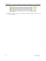
APPENDIX 13: Connection of data logger with output relay module and external terminal
ATTENTION – cable is crossed, if wired different way than on the figure, connected circuits
can be damaged !
36
ie-ms2-ms5app-08
APPENDIX 14: Setting of client administration and passwords
This appendix describes protection of data logger MS+, MS5 against unauthorized access. This
issue is applied to the following levels:
Communication encryption
Users and passwords list
Login dialog settings
Program security
Data logger security
Synchronization of users and passwords list (centralized administration of users and
passwords)
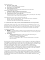
1. Communication encryption
It’s protection of data which are transferred between computer and data logger by entered password. The
reason of communication encryption is protection against interception of the transferred data in the network
(intranet/internet). This data could be decoded because documents about data logger communication
protocol is commonly available.
Communiction encryption option and password settings is available in the data logger configuration (tab
“Common”, option “Communication data encryption by password”).
The way to input password for communication encryption is possible set in program options (tab “Users and
passwords”, section “Password for communication encryption”).
Passwords are permanently saved in computer
During first communication initialization with data logger is user asked for the password.
Password is saved to the computer. Then password is used in communication with data
logger automatically even after re-run of the program.
Passwrods are temporarily stored while application is running
During first communication initialization with data logger is user asked for the password.
Password is remembered by program. Then password is used in communication with data
logger automatically until program is closed (password will be lost). If the program is
started up afterwards, user is asked for the password again.
ie-ms2-ms5app-08
37
2. Users and passwords list
Security is commonly implemented by the system of users and passwords list where users have been given
access rights. The list of authorized users is applied in the level of data logger security (list in the data
logger) and in the level of program security (list in the program), it means, in the system can be two or more
independent lists of users and passwords (system is computer/computers with connection of one or more
data loggers).
The list of users and passwords can contain up to 16 users with following properties:
User name – unique user name for the access to the account (login).
Name and surname – name and surname of the user.
Description – description of the user account.
Password – user password creation (available through new account creating only).
Password confirmation – user password confirmation (available through new account creating only).
Change password – password change of the selected user (available through account editing only).
Group membership – membership in the group of users
User with limited rights – it is possible define access to the HW and SW protected functions
except access to the security administration for the member of this group.
Administrator – member of this group has unlimited access to the HW and SW protected functions
including security administration.
SW protected functions – distinguished functions for work with the program.
HW protected functions – distinguished functions for work with data logger.
Export – save list of users and passwords to the file.
Import – load list of users and passwords from the file.
List of users and passwords stored in the file can be used for transfer of users between program installations
on more computers, for theirs back-up or for import to the data logger. This file should be stored on safe
place!
3. Login dialog settings
Option “Login dialog settings” is designed for settings of behaviour of login dialogs (is related to program
security and data logger security also!).
38
ie-ms2-ms5app-08
At application startup only
Login dialog is used only once, at the time of first run. Entered access data is used at the next time
automaticaly until access data become invalid. Then it’s required to enter access data again. Data
become invalid for example in this cases: program shut down, user log out, access data are invalid.
Before every protected functions
Login data have to enter every time when access rights verification is required. It’s access
verification to some protected functions almost.
4. Program security
Program security (SW security) is protection against unauthorized access to the program and restriction of
program functions according to settings of users rights. It limits access to the program and program’s
“Protected functions” according to users rights defined in the list of users and passwords in the program.
By activating of the option “SW security” is set administrator account and it’s required new password for it.
It’s required login to the user account after settings is applied and/or program startup otherwise you can’t
work with the program.
Current user can be logged out by option “User logout...” from the menu File.
SW protected functions:
Program options settings
Protection of program options setting (Folders, Display, Autodownload).
Communication settigns
Protection of communication settings editing (list of communication interfaces and data loggers).
Clear display statistics
ie-ms2-ms5app-08
39
Protection of statistics reset of the current data logger in the Display mode on the corresponding tab.
Clear display alarms
Protection of alarm records erasing of the current data logger in the Display mode on the
corresponding tab.
Delete event viewer messages
Protection of messages deleting in the event viewer.
Other functions of the security:
User same security settings and user list for all dataloggers
See Synchronization of users and passwords list (centralized administration of users and
passwords).
User activity logging
By activating this option is possible log specific users activity. Logged events are stored and
available to show through event viewer.
5. Data logger security
Data logger security (HW security) is protection against unauthorized access to the data logger and
restriction of data logger configuration possibilities according to settings of users rights. It limits
access to the data logger, data logger’s “Protected functions” and configuration possibilities
according to users rights defined in the list of users and passwords in the data logger.
By activating of the option “Protection of access to HW functions” is set administrator account and
it’s required new password for it. User accounts of data logger is possible edit by button “Users
and passwords”. If data logger security is active, it’s performed verification of users rights during
each of access attempt to the data logger (it depends on settings of option “Login dialog settings”,
eventually on data logger account synchronization with computer).
Data logger serurity is possible set just in case communication encryption is active.
40
ie-ms2-ms5app-08
HW protected functions:
Data logger settings writing
User can save performed changes to the data logger.
Erase memory, reset counter inputs
Alarm confirmation by PIN1
User is authorized to cancel (confirm) alarm signalization base on assigned PIN.
Another settings of data logger security:
Confirmation of alarm signalization protected by PIN1
PIN1 settings is available in user account (see HW protected functions).
Condition settings from PC protected by PIN1
Switching between states of remote conditions in Display mode is protected by PIN1. PIN1 settings
is available in user account (see HW protected functions).
Alarm signalization is possible cancel (confirm) by following ways:
- By option “Deactivate alarm signalization” from the program menu (menu Configuration)
- By button “Enter” on the data logger keyboard
- In the menu of data logger keyboard (data loggers with display only)
6. Synchronization of users and passwords (centralized administration of users and passwords)
Synchronization means using the same security settings and users list for all dataloggers. It can be set by
appropriate option in the program options on the tab “Users and passwords”. If it’s active, there’s only one
and centralized users list in the system. This list is managed in the program options and it’s distributed to
the data loggers. If data logger is synchronized, users account editing is unavailable in the data logger.
List distribution is performed:
Globally
After changes of program options is confirmed, request for synchronization is rised. It the request is
confirmed, synchronization is performed for all available data loggers (see list of data loggers in the
communication settings).
Distributively
o Through program menu (option “Update users and passwords in datalogger”)
Synchronization of selected data logger is performed.
o Before access to data logger configuration
After dialog of synchronization request is confirmed, synchronization of selected data
logger is performed.
Synchronization checking is made through each of access attempt to the data logger configuration.
If data logger is not synchronized for some reason, user is requested to perform synchronization of
date logger. Synchronization process can be made by user with administrator access rights for data
logger only (in data logger without security is every approaching user administrator).
If security in data logger is not active due to synchronization, it’s switched on including
communication encryption. If communication encryption was switched on due to synchronization,
user is asked for new password of communication encryption to create it. If user don’t create this
password, synchronization of the selected data logger is canceled.
If you switch off synchronization, it remains valid last known configuration in every data logger
(configuration, let us say security is without changes in data logger) and security in data logger is
administrated distributively for selected data logger. It’s possible switched off security for selected
data logger and it means switched off synchronization for this data logger (administrator only).
ie-ms2-ms5app-08
41
Examples of security settings
1. Restriction of the program startup and functionality, data logger has no security
User wants to secure the system on the computer side only.
Characteristics
-
Security (users and passwords) is set in computer only. If data logger is connected to other
computer that has no security, access to the data logger is without protection (unlimited).
It’s possible to set restriction of work with program for the user (see SW protected functions).
Easy settings
Low level of the security
Settings
Switch on security in program options, option “SW security”, and create new administrator password.
Add/remove user to/from the list of users and passwords.
Edit user’s properties in the list of users and passwords – button “Properties”. In user account on the tab
“Details” can be set restriction for work with program (SW protected functions).
Save the settings. After you set the settings, log in to the program.
2. Data logger with active security and with access from more computers
User wants to secure selected data logger and it don’t make any difference computer security (program
security). For example, data logger connected by ethernet and it can be available from more computers.
Characteristics
-
42
Security (users and passwords) is set in data logger only.
Communication between computer and data logger is encrypted by password.
You need to know login data (name and password) for the access to data logger. This data can be
stored in the computer. When you are connected to data logger from any other computer, you need
to enter login data again.
It can be set restriction of work with data logger for the user (see HW protected functions).
ie-ms2-ms5app-08
-
Higher level of security
Settings
Switch on data logger security, option “Security On/Off”, and create new administrator password.
It can be edit user’s properties in the section “users list”. In user’s properties (user account) on the tab
“Details” can be set restriction for work with data logger (HW protected functions).
Save the settings (configuration).
3. Identification of user who canceled (confirmed) alarm signalization
It’s possible to record events of alarm signalization revocation in the measured values and identify the user
who performed this action (this record is available with co-operation with identification of user only).
Identification of user who canceled (confirmed) alarm signalization is available only, if data logger seturity
is active.
Characteristics
-
-
There is active security (users and passwords) in the data logger.
Communication between computer and data logger is encrypted by password.
You need to know login data (name and password) for the access to data logger. This data can be
stored in the computer. When you are connected to data logger from any other computer, you need
to enter login data again.
It can be set restriction of work with data logger for the user (see HW protected functions).
Higher level of security
Alarm signalization revocation is performed by enter PIN1 on the data logger keyboard or in the
computer.
ie-ms2-ms5app-08
43
Settings
First follow steps from previous example (ex. 2). Go to the tab “Details” in user account. Select option
“Alarm confirmation by PIN1” and create new PIN1 for selected user. You can repeat this step for any
number of users in the list.
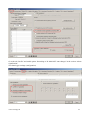
Enable option “Confirmation of alarm signalization protected by PIN1” in the window of data
logger configuration – tab “Common”. In the section “Confirmation of alarm signalization” select
option from where can be alarm signalization canceled (confirmed).
44
ie-ms2-ms5app-08
Go to the tab “Profile” and enable option “Recording of ALARM OUT state changes” in the section “Alarm
signalization”.
Save data logger settings (configuration).
ie-ms2-ms5app-08
45
4. Security of more data loggers with centralized administration from one computer
User works with many data loggers from one place (computer) and this data loggers share security (users
and passwords).
Characteristics
-
-
There is active security (users and passwords) in all of data loggers.
Communication between computer and data loggers is encrypted by password.
You need to know login data (name and password) for the access to the system. This data can be
stored in the computer. When you are connected to data loggers from any other computer, you need
to enter login data again.
Program checks changes of the security (users and passwords) settings and update it in the data
loggers.
It can be set restriction of work with data logger (HW protected functions) and restriction of work
with program (SW protected functions) for the user.
High level of security
Settings
First follow steps from example 1. In addition enable option “Use same security settings and user list for all
data loggers”.
After settings confirmation log in to the program as administrator. Then confirm synchronization request
(button YES in the dialog).
46
ie-ms2-ms5app-08
Software set up security and communication encryption for each of available data loggers through
synchonization process. If communication encryption is switched on, program require to enter new
password of communication encryption. Changes of security (users and passwords) in data logger require
memory deleting, that is why user is inform about it and may download current records from data logger
before memory is deleted.
If you select “Cancel” option, current data logger is skipped (synchronization is not applied on it) and
synchronization process continue with next available data logger from the list.
User is inform about synchronization finalization by summary table with synchronization result.
ie-ms2-ms5app-08
47
APPENDIX 15 Advanced settings of data logger
Follow this appendix If you need:
to activate external terminal
to activate output relays module
to activate Ethernet interface in data logger
to invert behavior of ALARM OUT output
to set data logger for SMS messaging
Procedure:
Click right mouse button on icon of user program for data logger, select Options-ShortcutTarget, where append text of /master, e.g.:
"C:\Program Files\COMET\MS234p\Ms_234p.exe" /master
ATTENTION – between quotation mark and slash must be a space. Then confirm the
window.
Click this icon to run the program.
after reading configuration of data logger another folder appears Advanced options
do required settings and then click button OK – ATTENTION, all recorded data in data
logger will be erased!
Remove text /master from text in the desktop shortcut
Notes:
Activation of external terminal and relay outputs is necessary to make data logger
communicate with these devices. If these items are active, then you can set and use them in
usual data logger configuration.
Activation of Ethernet interface is necessary to switch on this interface on data logger
display or in user SW.
Inversion behavior of output ALARM OUT is suitable, when you need status without data
logger power to consider as alarm. With inverse behavior of this output relay is closed in
the state without alarm and there is a voltage present at the output.
Advanced setting of SMS messages:
You can change communication speed between data logger and modem (it has
nothing to do with communication speed for communication with computer,
even if one RS232 interface is used for both). It is recommended to set 9600
Bd.
You can switch on flow control of RTS/CTS – usually it is not needed.
You can disable to link SMS messages into one long message. This function is
not supported by operators in some countries, that is why it is necessary to
disable to link SMS in particular situation. It concerns response to SMS Info,
which can sustain from up to four SMS messages.
Other selections concern rather diagnostics in solving problems with messages.
Keep default ticked Erase damaged messages from modem and not ticked End
SMS transaction in progress with error.
It is not enabled to set clock frequency of processor in master mode.
48
ie-ms2-ms5app-08